JP4293798B2 - Method for estimating transfer function of channel carrying multicarrier signal and multicarrier receiver - Google Patents
Method for estimating transfer function of channel carrying multicarrier signal and multicarrier receiver Download PDFInfo
- Publication number
- JP4293798B2 JP4293798B2 JP2003027495A JP2003027495A JP4293798B2 JP 4293798 B2 JP4293798 B2 JP 4293798B2 JP 2003027495 A JP2003027495 A JP 2003027495A JP 2003027495 A JP2003027495 A JP 2003027495A JP 4293798 B2 JP4293798 B2 JP 4293798B2
- Authority
- JP
- Japan
- Prior art keywords
- transfer function
- estimating
- channel
- value
- distortion
- Prior art date
- Legal status (The legal status is an assumption and is not a legal conclusion. Google has not performed a legal analysis and makes no representation as to the accuracy of the status listed.)
- Expired - Lifetime
Links
- 238000000034 method Methods 0.000 title claims description 30
- 238000012546 transfer Methods 0.000 title claims description 20
- 230000005540 biological transmission Effects 0.000 claims description 9
- 230000001360 synchronised effect Effects 0.000 claims description 8
- 230000001419 dependent effect Effects 0.000 claims 1
- 238000001914 filtration Methods 0.000 description 8
- 238000001228 spectrum Methods 0.000 description 8
- 238000010586 diagram Methods 0.000 description 6
- 230000000694 effects Effects 0.000 description 6
- 238000012545 processing Methods 0.000 description 5
- 230000003111 delayed effect Effects 0.000 description 3
- 238000013459 approach Methods 0.000 description 2
- 238000010420 art technique Methods 0.000 description 2
- 230000015556 catabolic process Effects 0.000 description 2
- 238000006731 degradation reaction Methods 0.000 description 2
- 238000011156 evaluation Methods 0.000 description 2
- 230000002238 attenuated effect Effects 0.000 description 1
- 230000015572 biosynthetic process Effects 0.000 description 1
- 238000004364 calculation method Methods 0.000 description 1
- 239000000969 carrier Substances 0.000 description 1
- 238000012937 correction Methods 0.000 description 1
- 238000013461 design Methods 0.000 description 1
- 238000001514 detection method Methods 0.000 description 1
- 238000005562 fading Methods 0.000 description 1
- 238000012886 linear function Methods 0.000 description 1
- 238000012417 linear regression Methods 0.000 description 1
- 238000005259 measurement Methods 0.000 description 1
- 238000000819 phase cycle Methods 0.000 description 1
- 238000005070 sampling Methods 0.000 description 1
Images


Classifications
-
- H—ELECTRICITY
- H04—ELECTRIC COMMUNICATION TECHNIQUE
- H04L—TRANSMISSION OF DIGITAL INFORMATION, e.g. TELEGRAPHIC COMMUNICATION
- H04L27/00—Modulated-carrier systems
- H04L27/26—Systems using multi-frequency codes
- H04L27/2601—Multicarrier modulation systems
- H04L27/2647—Arrangements specific to the receiver only
-
- H—ELECTRICITY
- H04—ELECTRIC COMMUNICATION TECHNIQUE
- H04L—TRANSMISSION OF DIGITAL INFORMATION, e.g. TELEGRAPHIC COMMUNICATION
- H04L25/00—Baseband systems
- H04L25/02—Details ; arrangements for supplying electrical power along data transmission lines
- H04L25/0202—Channel estimation
- H04L25/0224—Channel estimation using sounding signals
- H04L25/0228—Channel estimation using sounding signals with direct estimation from sounding signals
- H04L25/023—Channel estimation using sounding signals with direct estimation from sounding signals with extension to other symbols
- H04L25/0232—Channel estimation using sounding signals with direct estimation from sounding signals with extension to other symbols by interpolation between sounding signals
- H04L25/0234—Channel estimation using sounding signals with direct estimation from sounding signals with extension to other symbols by interpolation between sounding signals by non-linear interpolation
Landscapes
- Engineering & Computer Science (AREA)
- Computer Networks & Wireless Communication (AREA)
- Signal Processing (AREA)
- Physics & Mathematics (AREA)
- Nonlinear Science (AREA)
- Power Engineering (AREA)
- Cable Transmission Systems, Equalization Of Radio And Reduction Of Echo (AREA)
- Noise Elimination (AREA)
- Radio Transmission System (AREA)
Description
【0001】
【発明の属する技術分野】
本発明は、直交周波数分割多重(OFDM)受信機のようなマルチキャリアシステムに関する。詳細には、本発明は、たとえば、特に無線伝送のマルチパス干渉に起因して送信機出力と受信機入力との間で生じる可能性があるマルチキャリア伝送の歪みを補正できるようにするために、伝送のチャネル伝達関数を推定することに関する。
【0002】
【従来の技術】
OFDMを用いる場合、各サブキャリア上の個々の変調シンボルはそれぞれ長い持続時間を有する。このようにして、反射された信号を受信する特定の受信機によって引き起こされるチャネルの劣化、いわゆるマルチパス歪みおよびチャネル遅延スプレッドが大きく低減される。これは、各サブキャリア上のデータシンボルの持続時間が反射によって引き起こされる遅延スプレッドよりも非常に長いときに、反射されたパスからの遅延信号上のデータが、直接パス上で以前に伝送されたデータとほとんど重複しないために生じる。しかしながら、反射された信号が存在する場合には、チャネルの周波数応答が影響を及ぼされ、OFDM信号内の個々のサブキャリアが減衰される可能性がある。チャネル推定器は、この影響を計算し、歪みを補償できるようにする。
【0003】
データ速度を高めるために、多くの場合に同期変調が用いられる。同期変調は、データを搬送するために、振幅および位相の絶対値を利用する。これにより、その信号はチャネルの劣化に対して非常に影響を受けやすくなる。このため、同期変調されたOFDMを用いるとき、受信機によって知られている変調値を有する「パイロット」サブキャリアが通常、主要信号とともに送信される。その後、受信されたパイロットは、受信されるはずのパイロットと比較され、その差を用いてチャネル歪みが推定され、除去される。この手順は等化と呼ばれる。
【0004】
たとえば地上波デジタルビデオ放送(DVB−T)、地上波統合サービスデジタル放送(ISDB−T)、無線ローカルエリアネットワーク(WLAN:HIPERLAN/2、IEEE802.11a、MMAC)およびデジタルオーディオ放送(DAB)などの現在の無線伝送方式は全て、マルチパス信号の影響を解消できるようにするために、パイロットサブキャリアを利用する。DVB−T、ISDB−Tおよび無線LANの場合には、パイロットは、ある一定の時間にある一定のサブキャリア上でのみ送信される。DVB−TおよびISDB−Tの場合、パイロットサブキャリアは各OFDMシンボル上で送信されるが、そのサブキャリアのうちのいくつかにおいてのみ送信される可能性がある。
【0005】
【発明が解決しようとする課題】
既知のパイロット間のデータサブキャリア上のチャネルによって引き起こされる信号歪みを補正できるようにするために、現在の受信機は、フィルタおよび/または線形補間回路を用いて、パイロット間を補間し、その補間された結果を用いて、そのチャネルを補正する。多くの場合に、いくつかのパイロットが用いられ、周波数方向および時間方向においてフィルタリングを行い、雑音の影響を除去する。しかしながら、反射された二次的な信号がメインパスOFDM信号のシンボル持続時間に対して相対的に長い時間にわたって遅延される場合に生じることになるように、サブキャリア方向(すなわち、周波数方向)におけるチャネルの変動が急速である場合には、正確に補間することは難しい。さらに、フィルタに基づくチャネル等化のアプローチでは、信号スペクトルの縁部にあるサブキャリアを取り扱うことは難しい。低周波数の縁部では、スペクトルの縁部より下側で用いることができるパイロットが存在しない。同様に、高周波数の縁部では、それより高い周波数のパイロットサブキャリアが存在しない。これにより、フィルタを実装するのがより複雑になる。
【0006】
本発明の目的は、チャネル推定のための改善された信号処理を提供することである。
【0007】
【課題を解決するための手段】
本発明の種々の態様が併記の特許請求の範囲に記載される。
【0008】
別の態様によれば、信号が伝送されるチャネルの特性が、送信されたサブキャリア、詳細にはパイロットを用いることにより新しい態様で特定される。その特定は、隣接するパイロットサブキャリアの歪み値間で、チャネルによって導入される位相の特徴的な変化の値を求めることによりなされる。
【0009】
その後、そのチャネル応答を等化することにより、チャネル歪みを補償することができる。このシステムは一般に、マルチパス遅延スプレッドがOFDMシンボル長のより長い部分になるのにつれて、技法が徐々に劣化していく従来の補間あるいはフィルタリングよりも優れた結果を生み出す。これは、マルチパスチャネルによって引き起こされる信号スペクトルのリップルが、パイロット間隔に比べて密な間隔を有するようになるためである。その際、フィルタリングあるいは補間された推定値は厳密さを欠くようになる。
【0010】
種々の代替の実現可能性が想定される。
【0011】
たとえば、本発明は、2相位相変調あるいは4相位相変調システムにおいて、送信されたデータの信号コンスタレーションがわかっている場合には、パイロットを用いないマルチキャリアシステムに適用することもできる。したがって、データに基づく判定手順を用いることができ、少なくともいくつかのサブキャリアの場合に、導出された複素データ値を用いて、1組の所定の取り得るデータ値のうちの、最も近い値が選択される。その後、導出された複素値と選択された所定の値とを比較することにより、データ歪み値を判定することができる。これにより、他のサブキャリアの場合の歪み推定値を判定できるようになる。したがって、いくつかのサブキャリアによって搬送されるデータを判定できるものと仮定すると、他のサブキャリアによって搬送される値の判定を困難にする雑音を補償することができる。
【0012】
本発明は主に、チャネル等化の目的を果たすための推定されたチャネル伝達関数に関連して記載されることになるが、それとは別に、あるいはそれに加えて、マルチキャリア信号の2つのバージョン間の遅延を測定するための技法を用いることができる。これは、種々のサブキャリアの歪み値間の位相変化がこの時間遅延に依存し、それゆえ、位相が変化する速度を判定することにより、時間遅延を計算することができるためである。したがって、本発明は、時間遅延が、その一方が信号を反射する物体の位置であり、もう一方が別の反射物体の位置あるいはマルチキャリア信号の信号源(その信号の受信機の位置の可能性もある)である、2つの場所の間の距離を表す距離測定あるいは物体検出システムに適用することができる。
【0013】
【発明の実施の形態】
ここで本発明を具現する構成を、添付の図面を参照しながら例を用いて記載する。
【0014】
OFDM受信機2が図1に示される。OFDM信号は、マルチパス反射を受けている可能性があり、アンテナ4で受信され、ダウンコンバータ6によって適当な中間周波数(IF)にダウンコンバートされる。その後、その信号はサンプリングされ、それ自体でよく知られている方法を用いて、IF/ベースバンドコンバータ8によって同相および直交成分(複素数)に変換される。その後、このサンプリングされた時間領域信号は、受信機の高速フーリエ変換(FFT)信号処理部10によって周波数領域に変換される。受信機が、サンプルクロック及び周波数同期部12、並びにシンボル同期部14を用いて、その信号に正確に同調され、かつ同期される場合には、高速フーリエ変換信号処理部10の出力は、キャリア間干渉(ICI)がない、受信OFDMサブキャリアである。その後、これらのOFDMサブキャリアは、送信されたOFDMシンボル内のパイロット位置において得られるサンプリングされたチャネル周波数応答に基づいて、データサブキャリアの位置においてチャネル歪みを推定するために、かつチャネル推定結果を利用することによりデータサブキャリアの歪みを除去あるいは低減し、改善されたシステム性能を達成するために、チャネル推定及び等化部16に供給される。
【0015】
その後、等化されたデータサブキャリアは、復調及びデータ復号部18に供給される。ここまでに記載された技法は当分野において知られている。
【0016】
図2を参照すると、周波数に関してチャネル応答特性Rの急速な変動を引き起こすマルチパス干渉を受ける信号内の種々の周波数におけるパイロットサブキャリアの振幅の典型的なプロットが示される。従来技術による技法は、隣接するパイロットサブキャリアの対間を補間することにより、その応答特性Rを決定しようと試みる。
【0017】
こうして、各パイロットサブキャリアの場合に、たとえば、サブキャリアnのチャネル伝達関数のための値Pnを得るために、受信された信号と既知の変調値との比をとることにより、パイロット歪み値が計算される。図3を参照すると、周波数に対するチャネル伝達関数Tがプロットされる。線形補間を用いることにより、隣接するパイロットサブキャリア(実線で示される)間のデータサブキャリア(破線で示される)のためのチャネル伝達関数T値を概ね判定することができることは理解されよう。パイロットサブキャリアは、k番目のサブキャリア毎にパイロットサブキャリアになるように、等間隔で配置されるものと仮定される。間に現れるデータサブキャリアは、パイロットに対して指数iだけオフセットされる。ただしi=1、...、(k−1)である。線形補間のための従来技術の技法は、データサブキャリア(n+i)の場合に、以下の式のチャネル伝達関数を与える。
chn+i=Pn−(Pn−Pn+k)i/k
【0018】
しかしながら、そのように補間されたデータ歪み推定値は、図3から明らかなように、特にそのチャネル伝達関数Tの頂部と谷部の領域において不正確である可能性が高い。
【0019】
本発明によれば、チャネル推定及び等化部16のチャネル推定プロセスの場合に以下に記載される技法を用いることにより、これらの問題が低減される。以下の説明では、システムが最も効率的に動作するために、通常は受信される信号のメインあるいは直接波に関連付けられる成分である、そのチャネルの最も強いパスに受信機2が同期するものと仮定される。
【0020】
マルチパス歪みの結果として、主要応答あるいはチャネル振幅頂部領域に同期する受信機では、低周波数サブキャリアにおけるチャネル応答のサンプルのある特定の対間の差の位相が、高周波数のサブキャリアの別の特定の対の位相よりも大きくなる傾向があることが観測されている。それはチャネル内の総遅延量であり、それによって、周波数が高くなるのに応じて位相値が落ち込むようになる。この位相の動きは、位相回転変数αを確立するために利用することができ、結果として、根底をなすマルチパスチャネル応答の位相特性を近似する2パスモデルが生成される。実際に、最も強い2つのパスが支配的である。したがって、サブキャリア周波数に対してこの位相が変動する範囲αを判定することにより、データ歪み推定値を得るために、パイロット歪み値間のより正確な補間を実行することができる。
【0021】
受信機が直接波で受信される信号に対して同期し、τの遅延を有する単一の遅延反射信号が存在するものと仮定すると、2つのサブキャリア周波数におけるチャネル応答Pn、Pn+k間の差δPnの位相φnは、速度α=−δωτでサブキャリア周波数に対して変動するであろう。ここで、δωはサブキャリア間の角周波数の増分である。2パスシステムは、この位相の線形な変化を生み出すであろう。すなわちαは定数になるであろう。3つ以上のパスを有する典型的なマルチパスチャネルの場合、位相を周波数に対してプロットするとき、図4に示されるように、傾向としては直線が支配的であるが、それに沿ってある変動量のリップルが見られ、全てのパスからの総合的な影響を反映する。
【0022】
本発明の好ましい実施形態では、周波数に対する位相φnの変動が、たとえば直線であるものと仮定し、その線の傾きαを決定することにより計算され、これが実際にサンプリングされたチャネル応答の位相特性を近似する等価2パスモデルを表す。これは、それ自体が知られているようにして導出されることができる、以下の線形回帰関数を用いて行うことができる。

【0023】
別法では、αが一定ではなく、さらに複雑になる状況において、より高い精度を与えるために、サブキャリア周波数に対して、δPnの位相φnの変化を表す非線形関数を導出することができるであろう。
【0024】
2パスの状況の場合、各パスからの信号がλ0およびλ1であり、その間の時間遅延はτであり、さらにOFDM受信機内のFFT窓がλ0に同期する場合には、そのキャリア位置におけるチャネルの周波数応答は以下のように表されることができることが明らかである。
Pn=λ0+λ1e-j ω n τ (2)
chn+i=λ0+λ1e-j( ω n+i δω /k) τ (3)
Pn+k=λ0+λ1e-j( ω n+ δω ) τ (4)
したがって、以下の式が成り立つ。
δPn=Pn−Pn+k=λ1e-j ω n τ(1−e-j δωτ) (5)
Pn−chn+i=λ1e-j ω n τ(1−e-j δω /k) (6)
【0025】
式(5)を編成し直し、α=−δωτを代入すると、以下の式が生成される。
chn+i=Pn−λ1e-j ω n τ(1−e-j ω /k) (7)
【0026】
式(5)および(7)を組み合わせると、データキャリア位置n+iにおけるチャネル応答は以下のようになる。
chn+i=Pn−(Pn−Pn+k)(1−ej ω /k)/(1−ej α) (8)
【0027】
式(8)はi<0かつ0<i<kの場合に有効であることは理解されよう。類似のアプローチにしたがって、以下の式は、i>kかつ0<i<kの場合に有効であることは理解されよう。
式(8)および(9)は全体的に厳密な2パスチャネルの場合にのみ有効である。他のさらに一般的なマルチパスの状況の場合、それらの式は、チャネル利得に対する局部的な小信号の近似とみなされることになり、主要な場所を中心にした等価2パスモデルとして表される。
【0029】
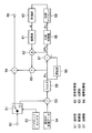
図5は、これらの手法を用いて動作するチャネル推定及び等化部16の構成ブロック図である。高速フーリエ変換信号処理部10(図1)におけるFFT演算の後に、OFDMサブキャリアは入力端子50から選別部51に供給され、選別部51は、どのサブキャリアがパイロットであるかを指示する、パイロットセレクタ52からの制御出力に基づいて、データサブキャリアからパイロットを分離する。その後、パイロットは除算器53に供給され、そこで、これらのパイロットサブキャリア上の既知の変調されたデータ(パイロットデータ源(アンテナ)4から得られる)54と比較することにより、そのパイロット位置におけるチャネル応答サンプルが求められる。
【0030】
除算器53からの出力は、チャネル応答サンプルのシリアルデータ列である。これらのサンプルは、一般にシンボルの境界においてグループ化し直され、フィルタ55内で遅れずに(in time)フィルタリング操作をするためのフレーム化されたデータが形成される。
【0031】
フィルタ55からのフィルタリングされたチャネルサンプルPnは、k分の1に間引かれたチャネルスペクトルを表しており(ただしkはフィルタリングされたチャネル応答サンプルの間隔である)、δPn=Pn−Pn+kを計算するために、遅延部56および減算器57にシリアルに供給される。
【0032】
減算器57の出力は位相計算器58に供給される。位相計算器58において、値δPnの位相値φnが逆三角関数を用いて計算される。その後、一連の位相値は、位相アンラッパ59において位相をアンラップするためにグループ化される。
【0033】
位相計算関数には固有の2πの曖昧さが存在するので、結果φnは、回転変数αの値を確立するために調整される(「位相アンラッピング」と呼ばれる)ことが必要な可能性がある。これは、n=n0+kから開始して、φnをφn-kとシリアルに比較し、φnがφn-k以上である場合には、その結果がφn-kより小さくなるまで、φnから2πを繰返し減算していくことにより行われる。
【0034】
所望により、この手順は、雑音に起因して誤りを生じる可能性を避けるように改良されることができる。たとえば、φnから何度も2πを減算することにより、アンラップされた値φnが変化する量が一様な傾向になるように制御することができる。たとえば、雑音による外乱を最小限に抑えるために、アンラップされた系列[...、φn-k、φn、φn+k、...]からの全てのφn−φn-kの平均値、すなわちδφnを計算することができ、第2段階において、その平均値δφnが、φnの最後の2π調整(アンラップ)が避けられることになるか否かを判定する際の指針として用いられる。その概念は、φn-k+δφnによって示されるようなφnの予測される直線上の傾向点にどの値、すなわちφnあるいはφn+2πのいずれが近いかを比較し、φnのために、より近い値のものを用いることである(正味の効果は、φnに関する最後の2π調整を継続するか、中止するかを決定することである)。しかしながら、これにより、構成がある程度複雑になり、パイプライン実装時にある余分な時間遅延が生じるようになる。
【0035】
アンラップされた位相系列はその後、評価(evaluation)部60に移送され、そこでパラメータα、すなわち回転変数が式(1)に従って求められる。その結果は、1組のデータサブキャリアチャネル応答補間利得を計算するために補間器61に供給され、その利得は、各データサブキャリアの場合に、
(1−ej ω /k)/(1−ej α)
あるいは
(1−ej ω /k)/(1−e-j α)である。
【0036】
k=3であり、全てのデータサブキャリアが2つのパイロット間に配置されるものと仮定すると、それぞれ2つの各データサブキャリア位置に対応して、利得の組においてk−1(すなわち2)個の複素利得が存在することになる。その組の利得要素はその後、減算器57から受信されるδPnによって乗算する、複素乗算器62に連続して供給される。その出力は、フィルタ55からPnも受信する加算器63に供給され、こうして、式(8)および(9)によって表されるような、データサブキャリア位置におけるチャネル応答の補間値が出力される。それは、nが最も近いパイロットである場合に式(8)が用いられ、n+kが最も近いパイロットであり、少なくとも信号スペクトルの縁部付近にあるデータサブキャリア位置の場合に、すなわちキャリアが一対のパイロット間に存在しない場合に式(9)が用いられるように構成される。他のデータサブキャリアの場合には、式(8)あるいは(9)のいずれか一方を用いることができる。
【0037】
データサブキャリアにおいてチャネル応答が補間された後に、加算器63からの出力は、複素除算器64に供給される。複素除算器64に対する他方の入力は、シリアルストリームでそれぞれ受信されるデータサブキャリアのFFT結果であり、その対応するチャネル応答によるこのストリームの除算の結果として、等化されたデータサブキャリアのストリームが生成され、チャネル歪みが除去あるいは低減される。この等化されたデータサブキャリアは、チャネル推定及び等化部16の出力端子66に現れ、復調及びデータ復号部18において、送信されたデータを再生するために復調される状態になっている。
【0038】
パラメータαが所定の閾値より小さい場合には、線形補間が用いられる。すなわち、(1−ej ω /k)/(1−ej α)および(1−ej ω /k)/(1−e-j α)がそれぞれi/kおよび−i/kによって置き換えられる。閾値は、特定の実施態様によって採用されるシステム設計および数値計算分解能に依存する。たとえば、固定小数点計算(整数による代数計算)を用いるアルゴリズムが実施されるものと仮定すると、閾値として、1−e-j αの大きさが、振幅が0ではなく、最下位ビット(LSB)を1つだけ有するようになる値が用いられる可能性がある。この状況は、たとえば、チャネルが1つの電波からなるとき(すなわち、マルチパス干渉が生じないフラットチャネル応答の場合)に生じるであろう。
【0039】
フィルタ55によって実行される遅れのないフィルタリングは、おそらく種々のシンボル内のパイロットが種々のサブキャリアに配置され(その場合、パイロットセレクタ52がシンボル間で異なるように動作する必要があるであろう)、および/またはおそらく各シンボル内の同じサブキャリアにおいて複数のパイロットを組み合わせることにより、補間の精度を改善することが、パイロットキャリアが複数のシンボルにわたって分布することに基づく場合に特に重要である。たとえば、DVB−TおよびISDB−Tシステムでは、シンボル内の規定されたパイロット分布よりも高い密度を得る唯一の可能性はいくつかの連続したシンボルをフィルタリングすることによる。DVB−T標準規格では、パイロットは、図6の「分散パイロット」と呼ばれるシステムに示されるようにローテーションしながら12番目のサブキャリア毎に送信される。たとえばサンプル・アンド・ホールド技法を用いて、遅れることなくサブキャリアをフィルタリングすることにより、4つのOFDMシンボル系列上の3番目のサブキャリア毎にチャネルの推定値を得ることができる。ISDB−T標準規格の場合、信号スペクトルは13個のセグメントに分割され、それらは全てが同期変調を含み得るとは限らない。同期セグメントの場合、パイロットサブキャリアはDVB−Tの場合と同じように、分散パイロットとして規定される。
【0040】
別法では、フィルタリングは、パイロットが同じサブキャリア位置において繰り返される一群の連続したシンボルの中で線形補間することにより達成されることができる。DVB−TおよびISDB−Tの場合には、これは、性能の改善を達成することはできるが、7シンボルにわたってフィルタリングする必要があるであろう。
【0041】
しかしながら、現在のOFDMシンボル内のパイロットのみを用いて補間することができる。これは、マルチパスフェージングが非常に高速であり、結果として、時間方向に沿ったフィルタリングが有効でなくなる、いくつかのチャネル条件の場合に適している可能性がある。周波数領域においてサンプリング距離が大きくなることに関する主な問題点は、対応することができるマルチパス遅延時間スプレッドが小さくなることを含む。原理的には、そのアルゴリズムによって取り扱うことができる時間遅延スプレッドは、以下の式のように、kと、OFDMサブキャリア間隔周波数δfOFDMとによって決定される。
時間スプレッド=1/(kδfOFDM)
【0042】
別の実施態様では、OFDMキャリアスペクトルが多数のセクションに分割され、補間が各セクションにおいて別々に実行される。セクションに基づくモデリングは、ISDB−Tのようなセグメントに基づくOFDM送信方式において、いくつかの固有の利点を有する。この別の実施態様では、雑音の影響の増加を招き、システム性能を低下させる可能性があるので、セクションが、あまりにも小さく、多数のサンプリングされた周波数応答点を有する部分に分割されるのを避けるように注意を払わなければならない。
【0043】
さらに別の実施態様は、回転角度変数αを遅れずにフィルタリングし、フィルタ出力を用いて、位相角アンラッピング操作を誘導することを含む。セクションへの分割に基づく実施態様では、以前のセクションからのα値を用いて、現在のセクションの位相アンラッピング操作を誘導することもできる。これらの別の実施態様によって、パイプライン形成を簡単にし、スループットの待ち時間を短縮できるようになる。
【0044】
本発明の別の実施態様では、マルチキャリア信号の2つのバージョン間の時間遅延が決定される。これは、上記のようにして位相回転変数αを計算し、その後、時間遅延τ=α/(−δω’)を計算することにより達成される。ここでδω’はサブキャリア間の角周波数の増分である。この場合に、全てのサブキャリアが、既知のデータ値を搬送するパイロットとして用いられる可能性があり、等化(および後続の補間)は必要とされない可能性がある。
【0045】
【発明の効果】
本発明によれば、直交周波数分割多重(OFDM)受信機のようなマルチキャリアシステムにおいて、チャネル推定のための改善された信号処理を実現することができる。
【図面の簡単な説明】
【図1】 本発明の技法を適用することができるOFDM受信機のブロック図である。
【図2】 2つのパスチャネルから生じる信号のパイロットサブキャリアのスペクトルを示す図である。
【図3】 従来の線形補間技法から生じる補間誤差を示すための図である。
【図4】 マルチパス干渉を受ける信号のサブキャリアの歪みの変化を表す値の位相の典型的な傾向を示す図である。
【図5】 本発明によるチャネル推定および等化システムのブロック図である。
【図6】 OFDMシンボルの中のパイロットの分布の一例を示す図である。
【符号の説明】
2 OFDM受信機、4 アンテナ、6 ダウンコンバータ、8 IF/ベースバンドコンバータ、10 高速フーリエ変換信号処理部、12 サンプルクロック及び周波数同期部、14 シンボル同期部、16 チャネル推定及び等化部、18 復調及びデータ復号部、50 入力端子、51 選別部、52 パイロットセレクタ、53 除算器、54 既知の変調データ、55 フィルタ、56遅延部、57 減算器、58 位相計算器、59 位相アンラッパ、60 評価部、61 補間器、62 複素乗算器、63 加算器、64 複素除算器。[0001]
BACKGROUND OF THE INVENTION
The present invention relates to multi-carrier systems such as orthogonal frequency division multiplexing (OFDM) receivers. In particular, the present invention is intended to allow correction of multi-carrier transmission distortions that may occur, for example, between transmitter output and receiver input, particularly due to multi-path interference in wireless transmission. Relates to estimating the channel transfer function of the transmission.
[0002]
[Prior art]
When using OFDM, each modulation symbol on each subcarrier has a long duration. In this way, channel degradation, so-called multipath distortion and channel delay spread caused by a particular receiver receiving the reflected signal is greatly reduced. This is because the data on the delayed signal from the reflected path was previously transmitted on the direct path when the duration of the data symbols on each subcarrier is much longer than the delay spread caused by the reflection This happens because there is almost no overlap with the data. However, if a reflected signal is present, the frequency response of the channel can be affected and individual subcarriers in the OFDM signal can be attenuated. The channel estimator calculates this effect so that distortion can be compensated.
[0003]
Synchronous modulation is often used to increase data rates. Synchronous modulation utilizes absolute values of amplitude and phase to carry data. This makes the signal very susceptible to channel degradation. For this reason, when using synchronously modulated OFDM, “pilot” subcarriers with modulation values known by the receiver are usually transmitted with the main signal. The received pilot is then compared with the pilot that should be received and the difference is used to estimate and remove the channel distortion. This procedure is called equalization.
[0004]
For example, terrestrial digital video broadcasting (DVB-T), terrestrial integrated service digital broadcasting (ISDB-T), wireless local area network (WLAN: HIPERLAN / 2, IEEE802.11a, MMAC) and digital audio broadcasting (DAB) All current wireless transmission schemes use pilot subcarriers in order to be able to eliminate the effects of multipath signals. In the case of DVB-T, ISDB-T, and wireless LAN, the pilot is transmitted only on a certain subcarrier at a certain time. For DVB-T and ISDB-T, pilot subcarriers are transmitted on each OFDM symbol, but may only be transmitted on some of the subcarriers.
[0005]
[Problems to be solved by the invention]
In order to be able to correct for signal distortion caused by channels on data subcarriers between known pilots, current receivers use filters and / or linear interpolation circuits to interpolate between pilots and perform the interpolation The corrected result is used to correct the channel. In many cases, several pilots are used to perform filtering in the frequency and time directions to remove the effects of noise. However, in the subcarrier direction (ie frequency direction), as will occur if the reflected secondary signal is delayed over a relatively long time relative to the symbol duration of the main path OFDM signal. It is difficult to interpolate accurately when channel fluctuations are rapid. Furthermore, the filter-based channel equalization approach is difficult to handle subcarriers at the edge of the signal spectrum. At the low frequency edge, there are no pilots available below the spectrum edge. Similarly, at the high frequency edge there are no higher frequency pilot subcarriers. This makes it more complicated to implement the filter.
[0006]
An object of the present invention is to provide improved signal processing for channel estimation.
[0007]
[Means for Solving the Problems]
Various aspects of the invention are set out in the accompanying claims.
[0008]
According to another aspect, the characteristics of the channel on which the signal is transmitted are identified in a new way by using transmitted subcarriers, in particular pilots. This is done by determining the value of the characteristic change in phase introduced by the channel between adjacent pilot subcarrier distortion values.
[0009]
Thereafter, the channel distortion can be compensated by equalizing the channel response. This system generally produces better results than conventional interpolation or filtering where the technique gradually degrades as the multipath delay spread becomes a longer part of the OFDM symbol length. This is because the signal spectrum ripples caused by the multipath channel have a tighter spacing than the pilot spacing. At this time, the filtered or interpolated estimated value lacks strictness.
[0010]
Various alternative feasibility is envisioned.
[0011]
For example, the present invention can be applied to a multi-carrier system that does not use a pilot when the signal constellation of transmitted data is known in a two-phase phase modulation or four-phase phase modulation system. Thus, a data-based decision procedure can be used, and for at least some subcarriers, using the derived complex data value, the closest value of a set of possible possible data values is Selected. The data distortion value can then be determined by comparing the derived complex value with the selected predetermined value. This makes it possible to determine a distortion estimation value in the case of other subcarriers. Thus, assuming that data carried by some subcarriers can be determined, noise that makes it difficult to determine values carried by other subcarriers can be compensated.
[0012]
The invention will be described primarily in the context of an estimated channel transfer function to serve the purpose of channel equalization, but separately or in addition, between two versions of a multi-carrier signal. Techniques for measuring the delay of can be used. This is because the phase change between the distortion values of the various subcarriers depends on this time delay, and therefore the time delay can be calculated by determining the rate at which the phase changes. Thus, the present invention has the possibility that the time delay is the position of an object that reflects a signal on one side and the position of another reflecting object or the source of a multi-carrier signal (possibility of the receiver position of that signal It can also be applied to distance measurement or object detection systems that represent the distance between two locations.
[0013]
DETAILED DESCRIPTION OF THE INVENTION
Configurations embodying the invention will now be described by way of example with reference to the accompanying drawings.
[0014]
An
[0015]
Thereafter, the equalized data subcarrier is supplied to the demodulation and
[0016]
Referring to FIG. 2, a typical plot of the amplitude of pilot subcarriers at various frequencies in a signal subject to multipath interference that causes a rapid variation in channel response characteristic R with respect to frequency is shown. Prior art techniques attempt to determine the response characteristic R by interpolating between adjacent pilot subcarrier pairs.
[0017]
Thus, for each pilot subcarrier, for example, the value P for the channel transfer function of subcarrier nnTo obtain a pilot distortion value by taking the ratio of the received signal and the known modulation value. Referring to FIG. 3, the channel transfer function T versus frequency is plotted. It will be appreciated that by using linear interpolation, the channel transfer function T value for data subcarriers (shown in dashed lines) between adjacent pilot subcarriers (shown in solid lines) can be roughly determined. The pilot subcarriers are assumed to be arranged at equal intervals so as to become pilot subcarriers every k-th subcarrier. Data subcarriers appearing in between are offset by an index i relative to the pilot. Where i = 1,. . . , (K−1). The prior art technique for linear interpolation gives the following channel transfer function for the data subcarrier (n + i):
chn + i= Pn-(Pn-Pn + kI / k
[0018]
However, the data distortion estimates interpolated in this way are likely to be inaccurate, especially in the top and valley regions of the channel transfer function T, as is apparent from FIG.
[0019]
In accordance with the present invention, these problems are reduced by using the techniques described below in the case of the channel estimation and
[0020]
As a result of multipath distortion, in a receiver that is synchronized to the main response or the channel amplitude top region, the phase of the difference between a particular pair of samples of the channel response at low frequency subcarriers is different from that of high frequency subcarriers It has been observed that there is a tendency to be larger than a particular pair of phases. It is the total amount of delay in the channel, which causes the phase value to drop as the frequency increases. This phase motion can be used to establish the phase rotation variable α, resulting in a two-pass model that approximates the phase characteristics of the underlying multipath channel response. In fact, the two strongest paths are dominant. Therefore, by determining the range α in which the phase varies with respect to the subcarrier frequency, more accurate interpolation between the pilot distortion values can be performed in order to obtain the data distortion estimation value.
[0021]
Assuming that the receiver is synchronized to the signal received in the direct wave and there is a single delayed reflected signal with a delay of τ, the channel response P at the two subcarrier frequenciesn, Pn + kDifference δP betweennPhase φnWill vary with respect to the subcarrier frequency at a rate α = −δωτ. Here, δω is an increase in angular frequency between subcarriers. A two-pass system will produce a linear change in this phase. That is, α will be a constant. For a typical multipath channel with more than two paths, when plotting phase against frequency, as shown in FIG. 4, the trend is dominated by a straight line, but some variation along it A quantity of ripple is seen, reflecting the overall impact from all paths.
[0022]
In a preferred embodiment of the present invention, the phase φ with respect to frequencynIs assumed to be a straight line, for example, and is determined by determining the slope α of the line, which represents an equivalent two-pass model approximating the phase characteristics of the actually sampled channel response. This can be done using the following linear regression function, which can be derived in a manner known per se.
[0023]
Alternatively, to give higher accuracy in situations where α is not constant and becomes more complex, for a subcarrier frequency, δPnPhase φnIt would be possible to derive a non-linear function representing the change in.
[0024]
In a two-pass situation, the signal from each path is λ0And λ1And the time delay between them is τ, and the FFT window in the OFDM receiver is λ0Obviously, the frequency response of the channel at that carrier position can be expressed as:
Pn= Λ0+ Λ1e-j ω n τ (2)
chn + i= Λ0+ Λ1e-j ( ω n + i δω / k) τ (3)
Pn + k= Λ0+ Λ1e-j ( ω n + δω ) τ (4)
Therefore, the following equation holds.
δPn= Pn-Pn + k= Λ1e-j ω n τ(1-e-j δωτ(5)
Pn-Chn + i= Λ1e-j ω n τ(1-e-j δω / k(6)
[0025]
When the formula (5) is reorganized and α = −δωτ is substituted, the following formula is generated.
chn + i= Pn−λ1e-j ω n τ(1-e-j ω / k(7)
[0026]
Combining equations (5) and (7), the channel response at data carrier position n + i is:
chn + i= Pn-(Pn-Pn + k) (1-ej ω / k) / (1-ej α(8)
[0027]
It will be appreciated that equation (8) is valid when i <0 and 0 <i <k. It will be appreciated that following a similar approach, the following equation is valid for i> k and 0 <i <k.
Equations (8) and (9) are valid only for a strictly two-path channel as a whole. For other more general multipath situations, these equations would be considered as local small signal approximations to channel gain and represented as an equivalent two-path model centered around the main location. .
[0029]
FIG. 5 is a block diagram showing the configuration of the channel estimation and
[0030]
The output from the
[0031]
Filtered channel sample P from
[0032]
The output of the
[0033]
Since the phase calculation function has an inherent 2π ambiguity, the result φnMay need to be adjusted (called “phase unwrapping”) to establish the value of the rotation variable α. This is n = n0Starting from + k, φnΦnkCompared to serial, φnIs φnkIf this is the case, the result is φnkUntil smallernThis is done by repeatedly subtracting 2π from.
[0034]
If desired, this procedure can be modified to avoid the possibility of making errors due to noise. For example, φnBy subtracting 2π many times from, the unwrapped value φnIt is possible to control so that the amount of change becomes a uniform tendency. For example, to minimize noise disturbances, unwrapped sequences [. . . , Φnk, Φn, Φn + k,. . . ] All the φ fromn−φnkAverage value of δφnIn the second stage, the average value δφnIs φnThis is used as a guideline for determining whether or not the last 2π adjustment (unwrapping) is to be avoided. The concept is φnk+ ΔφnΦ as indicated bynWhich value to the predicted trend point on the line, i.e. φnOr φnCompare which of + 2π is closer, φnIs to use a closer value (the net effect is φnTo decide whether to continue or cancel the last 2π adjustment for However, this complicates the configuration to some extent and introduces an extra time delay when implementing the pipeline.
[0035]
The unwrapped phase sequence is then transferred to the
(1-ej ω / k) / (1-ej α)
Or
(1-ej ω / k) / (1-e-j α).
[0036]
Assuming k = 3 and all data subcarriers are placed between two pilots, k−1 (ie 2) in the gain set, corresponding to each of the two data subcarrier positions, respectively. There will be a complex gain. The set of gain elements is then received by δP from subtractor 57.nContinuously supplied to the
[0037]
After the channel response is interpolated in the data subcarrier, the output from the
[0038]
If the parameter α is smaller than a predetermined threshold, linear interpolation is used. That is, (1-ej ω / k) / (1-ej α) And (1-ej ω / k) / (1-e-j α) Are replaced by i / k and -i / k, respectively. The threshold depends on the system design and numerical resolution that is employed by the particular implementation. For example, assuming that an algorithm using fixed-point computation (integer algebra computation) is implemented, the threshold is 1-e-j αMay have a value such that the amplitude is not zero and has only one least significant bit (LSB). This situation may occur, for example, when the channel consists of one radio wave (ie in the case of a flat channel response where no multipath interference occurs).
[0039]
The delay-free filtering performed by
[0040]
Alternatively, filtering can be achieved by linear interpolation among a group of consecutive symbols in which pilots are repeated at the same subcarrier position. In the case of DVB-T and ISDB-T, this can achieve improved performance, but would need to be filtered over 7 symbols.
[0041]
However, it is possible to interpolate using only the pilots in the current OFDM symbol. This may be suitable for some channel conditions where multipath fading is very fast and as a result filtering along the time direction becomes ineffective. The main problem with increasing sampling distance in the frequency domain includes the reduced multipath delay time spread that can be accommodated. In principle, the time delay spread that can be handled by the algorithm is k and the OFDM subcarrier spacing frequency δf as follows:OFDMAnd determined by.
Time spread = 1 / (kδfOFDM)
[0042]
In another embodiment, the OFDM carrier spectrum is divided into a number of sections and interpolation is performed separately in each section. Section-based modeling has several inherent advantages in segment-based OFDM transmission schemes such as ISDB-T. In this alternative embodiment, the section is divided into parts that are too small and have a large number of sampled frequency response points, as this can lead to increased noise effects and reduce system performance. Care must be taken to avoid.
[0043]
Yet another embodiment includes filtering the rotation angle variable α without delay and using the filter output to induce a phase angle unwrapping operation. In an implementation based on division into sections, the alpha value from the previous section can also be used to derive the phase unwrapping operation for the current section. These alternative implementations can simplify pipeline formation and reduce throughput latency.
[0044]
In another embodiment of the invention, the time delay between two versions of the multicarrier signal is determined. This is achieved by calculating the phase rotation variable α as described above and then calculating the time delay τ = α / (− δω ′). Here, δω ′ is an increase in angular frequency between subcarriers. In this case, all subcarriers may be used as pilots carrying known data values, and equalization (and subsequent interpolation) may not be required.
[0045]
【The invention's effect】
According to the present invention, improved signal processing for channel estimation can be realized in a multicarrier system such as an orthogonal frequency division multiplexing (OFDM) receiver.
[Brief description of the drawings]
FIG. 1 is a block diagram of an OFDM receiver to which the techniques of the present invention can be applied.
FIG. 2 shows the spectrum of pilot subcarriers for signals arising from two path channels.
FIG. 3 is a diagram for illustrating an interpolation error resulting from a conventional linear interpolation technique;
FIG. 4 is a diagram illustrating a typical trend of the phase of values representing changes in subcarrier distortion of a signal subjected to multipath interference.
FIG. 5 is a block diagram of a channel estimation and equalization system according to the present invention.
FIG. 6 is a diagram illustrating an example of a pilot distribution in an OFDM symbol.
[Explanation of symbols]
2 OFDM receiver, 4 antenna, 6 down converter, 8 IF / baseband converter, 10 fast Fourier transform signal processing unit, 12 sample clock and frequency synchronization unit, 14 symbol synchronization unit, 16 channel estimation and equalization unit, 18 demodulation And data decoding unit, 50 input terminals, 51 selection unit, 52 pilot selector, 53 divider, 54 known modulation data, 55 filter, 56 delay unit, 57 subtractor, 58 phase calculator, 59 phase unwrapper, 60
Claims (12)
少なくともいくつかのサブキャリアの前記複素値は、そのサブキャリアのための歪み値を決定するために所定の値と比較され、前記方法は、
複数対の歪み値の各々について、歪み値の対の間の差を計算するステップであって、この計算した差の各々は関連した位相を持つ、該ステップと、
該計算した差の位相がサブキャリア周波数によって変動する速度を判定するステップと
を含む方法。A method for estimating a transfer function of a channel carrying a multicarrier signal using a receiver that derives a complex value from each subcarrier of the multicarrier signal,
The complex value of at least some subcarriers is compared with a predetermined value to determine a distortion value for that subcarrier, the method comprising:
For each of the plurality of pairs of distortion values, calculating a difference between the pair of distortion values, each of the calculated differences having an associated phase;
Determining the rate at which the phase of the calculated difference varies with subcarrier frequency .
請求項1に記載のマルチキャリア信号を搬送するチャネルの伝達関数を推定する方法。 In accordance with the determined velocity, channel transfer function for transporting the multi-carrier signal according to the data distortion further including claim 1: determining an estimate for the other subcarriers by interpolating the distortion values How to estimate.
請求項1又は2に記載のマルチキャリア信号を搬送するチャネルの伝達関数を推定する方法。The method of estimating a transfer function of a channel carrying a multicarrier signal according to claim 1, wherein the multicarrier transmission is OFDM transmission.
請求項3に記載のマルチキャリア信号を搬送するチャネルの伝達関数を推定する方法。The method of estimating a transfer function of a channel carrying a multicarrier signal according to claim 3, wherein the OFDM transmission is synchronous transmission.
請求項1又は2に記載のマルチキャリア信号を搬送するチャネルの伝達関数を推定する方法。The method of estimating a transfer function of a channel carrying a multicarrier signal according to claim 1 or 2, wherein the distortion value is determined for pilot subcarriers carrying a known data value.
請求項5に記載のマルチキャリア信号を搬送するチャネルの伝達関数を推定する方法。The method of estimating a transfer function of a channel carrying a multicarrier signal according to claim 5, wherein the distortion value is derived from pilot subcarriers distributed in a plurality of multicarrier symbols.
請求項6に記載のマルチキャリア信号を搬送するチャネルの伝達関数を推定する方法。The method of estimating a transfer function of a channel carrying a multicarrier signal according to claim 6, wherein the pilot subcarriers are arranged at different frequencies in different symbols.
請求項6又は7に記載のマルチキャリア信号を搬送するチャネルの伝達関数を推定する方法。The method for estimating a transfer function of a channel carrying a multicarrier signal according to claim 6 or 7, wherein at least some of the pilot distortion values are derived from a plurality of pilot subcarriers of the same frequency.
請求項1から請求項4までのいずれかに記載のマルチキャリア信号を搬送するチャネルの伝達関数を推定する方法。In the case of each subcarrier, the distortion value is selected from the set of predetermined possible values for the complex value derived from the subcarrier, and the derived complex value is selected. The method for estimating a transfer function of a channel carrying a multicarrier signal according to claim 1, wherein the transfer function is determined by comparing the selected value with the selected value.
その後、サブキャリアのためのデータ歪み推定値に従って、他のサブキャリアの複素値の振幅を調整するステップと
を含む方法。A method for correcting distortion in a multi-carrier receiver, the method comprising: estimating a transfer function of a channel using the method of claim 2 or a dependent claim thereof;
Then adjusting the amplitude of the complex values of the other subcarriers according to the data distortion estimate for the subcarrier.
その後、前記判定された速度から前記遅延を計算するステップと
を含む方法。A method for estimating a time delay between two versions of a multicarrier signal, the method comprising: estimating a transfer function of a channel using the method according to any of claims 1 to 9; ,
Then calculating the delay from the determined speed.
Applications Claiming Priority (2)
| Application Number | Priority Date | Filing Date | Title |
|---|---|---|---|
| EP02250843.6 | 2002-02-07 | ||
| EP02250843A EP1335552B1 (en) | 2002-02-07 | 2002-02-07 | Estimation of channel response and of delay in multicarrier systems |
Publications (2)
| Publication Number | Publication Date |
|---|---|
| JP2003264529A JP2003264529A (en) | 2003-09-19 |
| JP4293798B2 true JP4293798B2 (en) | 2009-07-08 |
Family
ID=27589163
Family Applications (1)
| Application Number | Title | Priority Date | Filing Date |
|---|---|---|---|
| JP2003027495A Expired - Lifetime JP4293798B2 (en) | 2002-02-07 | 2003-02-04 | Method for estimating transfer function of channel carrying multicarrier signal and multicarrier receiver |
Country Status (4)
| Country | Link |
|---|---|
| US (1) | US7286466B2 (en) |
| EP (1) | EP1335552B1 (en) |
| JP (1) | JP4293798B2 (en) |
| DE (1) | DE60217464T2 (en) |
Families Citing this family (22)
| Publication number | Priority date | Publication date | Assignee | Title |
|---|---|---|---|---|
| US20050059366A1 (en) * | 2003-09-16 | 2005-03-17 | Atheros Communications, Inc. | Spur mitigation techniques |
| DE10354468A1 (en) * | 2003-11-21 | 2005-06-23 | Rohde & Schwarz Gmbh & Co. Kg | Method and device for monitoring the carrier frequency stability of transmitters in a common wave network |
| DE102004047600A1 (en) * | 2004-09-30 | 2006-04-13 | Robert Bosch Gmbh | Method for synchronizing a sampling clock and synchronization unit for a multi-carrier receiving system |
| JP4561329B2 (en) * | 2004-11-18 | 2010-10-13 | ソニー株式会社 | Ranging system, transmitting terminal, receiving terminal, ranging method, and computer program |
| US7894818B2 (en) * | 2005-06-15 | 2011-02-22 | Samsung Electronics Co., Ltd. | Apparatus and method for multiplexing broadcast and unicast traffic in a multi-carrier wireless network |
| DE102005041520B3 (en) * | 2005-08-31 | 2006-12-07 | Oped Ag | Anti-decubitus underlayer mattress for bed has casing divided by undulating lines into cells filled with spherical infill |
| EA014591B1 (en) * | 2005-09-01 | 2010-12-30 | Шарп Кабусики Кайся | Transmission control method in wireless communication system |
| WO2007052649A1 (en) | 2005-10-31 | 2007-05-10 | Sharp Kabushiki Kaisha | Radio transmitter, radio communication system, and radio transmission method |
| EA012497B1 (en) * | 2005-10-31 | 2009-10-30 | Шарп Кабусики Кайся | Terminal apparatus, base station apparatus and communication system |
| JP5068668B2 (en) | 2005-12-20 | 2012-11-07 | シャープ株式会社 | Transmitter |
| EP1971042B1 (en) | 2005-12-26 | 2014-07-30 | Huawei Technologies Co., Ltd. | Wireless transmitter and wireless transmission method |
| KR100784176B1 (en) | 2006-01-17 | 2007-12-13 | 포스데이타 주식회사 | Channel estimation method of mobile terminal in radio communication system and channel estimator of enabling the method |
| KR100896203B1 (en) | 2006-02-24 | 2009-05-12 | 삼성전자주식회사 | Apparatus and method for channel estimation for data demodulation in broadband wireless access system |
| US7602853B2 (en) | 2006-04-17 | 2009-10-13 | Mediatek Inc. | Method and apparatus for channel estimation |
| US20080069250A1 (en) * | 2006-09-18 | 2008-03-20 | Conexant Systems, Inc. | Multipath processing systems and methods |
| US9515857B2 (en) * | 2006-10-11 | 2016-12-06 | Lantiq Beteiligungs-GmbH & Co. KG | Methods and systems for adaptive communication |
| US7907673B2 (en) * | 2006-10-26 | 2011-03-15 | Telefonaktiebolaget L M Ericsson (Publ) | Robust and low-complexity combined signal power estimation |
| US8027395B2 (en) * | 2006-11-03 | 2011-09-27 | Maxlinear, Inc. | Edge MMSE filters |
| US7961806B2 (en) | 2007-01-23 | 2011-06-14 | Mediatek Inc. | Power adaptive channel estimation for a multi-path receiving |
| US20090245092A1 (en) * | 2008-03-28 | 2009-10-01 | Qualcomm Incorporated | Apparatus, processes, and articles of manufacture for fast fourier transformation and beacon searching |
| US7944999B2 (en) * | 2008-04-04 | 2011-05-17 | Newport Media, Inc. | Robust fine frequency and time estimation in mobile multimedia multicast system receivers |
| TWI382683B (en) * | 2009-05-06 | 2013-01-11 | Ind Tech Res Inst | Method for pre-compensating for time delay incurred by chromatic dispersion, multi-subcarrier waveform generator employed therefor, and transmitter having the multi-subcarrier waveform generator |
Family Cites Families (10)
| Publication number | Priority date | Publication date | Assignee | Title |
|---|---|---|---|---|
| US5903823A (en) * | 1995-09-19 | 1999-05-11 | Fujitsu Limited | Radio apparatus with distortion compensating function |
| JPH09261086A (en) * | 1996-03-27 | 1997-10-03 | Mitsubishi Electric Corp | Interference wave elimination device and interference wave elimination method |
| US5867478A (en) * | 1997-06-20 | 1999-02-02 | Motorola, Inc. | Synchronous coherent orthogonal frequency division multiplexing system, method, software and device |
| KR100265735B1 (en) * | 1997-11-25 | 2000-09-15 | 윤종용 | OFDM receiver for jointing FFT window position recovery and sampling clock control and method therefor |
| JP3090138B2 (en) * | 1999-02-04 | 2000-09-18 | 日本電気株式会社 | Receiving machine |
| US7058002B1 (en) * | 1999-04-22 | 2006-06-06 | Nippon Telegraph And Telephone Corporation | OFDM packet communication receiver |
| US6542560B1 (en) * | 1999-04-23 | 2003-04-01 | Lucent Technologies Inc. | Method of channel estimation and compensation based thereon |
| US6985432B1 (en) * | 2000-01-28 | 2006-01-10 | Zion Hadad | OFDM communication channel |
| JP4284813B2 (en) * | 2000-02-18 | 2009-06-24 | 株式会社デンソー | OFDM receiver |
| US6850481B2 (en) * | 2000-09-01 | 2005-02-01 | Nortel Networks Limited | Channels estimation for multiple input—multiple output, orthogonal frequency division multiplexing (OFDM) system |
-
2002
- 2002-02-07 EP EP02250843A patent/EP1335552B1/en not_active Expired - Lifetime
- 2002-02-07 DE DE60217464T patent/DE60217464T2/en not_active Expired - Lifetime
-
2003
- 2003-01-30 US US10/353,928 patent/US7286466B2/en active Active
- 2003-02-04 JP JP2003027495A patent/JP4293798B2/en not_active Expired - Lifetime
Also Published As
| Publication number | Publication date |
|---|---|
| EP1335552A1 (en) | 2003-08-13 |
| DE60217464D1 (en) | 2007-02-22 |
| EP1335552B1 (en) | 2007-01-10 |
| US20030169682A1 (en) | 2003-09-11 |
| DE60217464T2 (en) | 2007-11-15 |
| US7286466B2 (en) | 2007-10-23 |
| JP2003264529A (en) | 2003-09-19 |
Similar Documents
| Publication | Publication Date | Title |
|---|---|---|
| JP4293798B2 (en) | Method for estimating transfer function of channel carrying multicarrier signal and multicarrier receiver | |
| US8098567B2 (en) | Timing adjustments for channel estimation in a multi carrier system | |
| US7450654B2 (en) | Method and apparatus for multicarrier channel estimation and synchronization using pilot sequences | |
| US8345734B2 (en) | Time error estimation for data symbols | |
| EP1624602B1 (en) | Demodulation device and demodulation method | |
| US7133479B2 (en) | Frequency synchronization apparatus and method for OFDM systems | |
| JP4125715B2 (en) | Method and apparatus for synchronizing initial frequency in OFDM system | |
| JP4655241B2 (en) | Receiving device, receiving method, and program | |
| KR101468514B1 (en) | Methods and an apparatus for estimating a residual frequency error in a communications system | |
| JP5307797B2 (en) | Reception device, reception method, reception program, integrated circuit, and digital television | |
| JP2004214962A (en) | Ofdm demodulator | |
| JP2005287043A (en) | Receiver | |
| US20080267273A1 (en) | Method and a System for Estimating a Symbol Time Error in a Broadband Transmission System | |
| JP5242599B2 (en) | Timing adjustment for channel estimation in multi-carrier systems | |
| JP2004228853A (en) | Ofdm receiving device and data demodulation method | |
| US8059736B2 (en) | Orthogonal frequency division multiplexing receiver | |
| KR100213100B1 (en) | Frequency error corrector for orthogonal frequency division multiplexing and method therefor | |
| WO2007096663A2 (en) | Ofdem channel estimation systems | |
| JP3756121B2 (en) | OFDM demodulator and power weighting method | |
| US8451966B2 (en) | Information processor and information processing method, display device, and program | |
| JP5995703B2 (en) | Equalizer, equalization method, and receiver | |
| KR100697526B1 (en) | Tracking device for digital broadcast receiver | |
| JP5722472B2 (en) | Method for estimating residual frequency error in a communication system | |
| JP2004304591A (en) | Ofdm demodulator and method |
Legal Events
| Date | Code | Title | Description |
|---|---|---|---|
| A621 | Written request for application examination |
Free format text: JAPANESE INTERMEDIATE CODE: A621 Effective date: 20060201 |
|
| A131 | Notification of reasons for refusal |
Free format text: JAPANESE INTERMEDIATE CODE: A131 Effective date: 20080902 |
|
| A521 | Request for written amendment filed |
Free format text: JAPANESE INTERMEDIATE CODE: A523 Effective date: 20081202 |
|
| TRDD | Decision of grant or rejection written | ||
| A01 | Written decision to grant a patent or to grant a registration (utility model) |
Free format text: JAPANESE INTERMEDIATE CODE: A01 Effective date: 20090310 |
|
| A01 | Written decision to grant a patent or to grant a registration (utility model) |
Free format text: JAPANESE INTERMEDIATE CODE: A01 |
|
| A61 | First payment of annual fees (during grant procedure) |
Free format text: JAPANESE INTERMEDIATE CODE: A61 Effective date: 20090407 |
|
| FPAY | Renewal fee payment (event date is renewal date of database) |
Free format text: PAYMENT UNTIL: 20120417 Year of fee payment: 3 |
|
| R150 | Certificate of patent or registration of utility model |
Free format text: JAPANESE INTERMEDIATE CODE: R150 Ref document number: 4293798 Country of ref document: JP Free format text: JAPANESE INTERMEDIATE CODE: R150 |
|
| FPAY | Renewal fee payment (event date is renewal date of database) |
Free format text: PAYMENT UNTIL: 20120417 Year of fee payment: 3 |
|
| S111 | Request for change of ownership or part of ownership |
Free format text: JAPANESE INTERMEDIATE CODE: R313113 |
|
| S631 | Written request for registration of reclamation of domicile |
Free format text: JAPANESE INTERMEDIATE CODE: R313631 |
|
| FPAY | Renewal fee payment (event date is renewal date of database) |
Free format text: PAYMENT UNTIL: 20120417 Year of fee payment: 3 |
|
| R360 | Written notification for declining of transfer of rights |
Free format text: JAPANESE INTERMEDIATE CODE: R360 |
|
| R370 | Written measure of declining of transfer procedure |
Free format text: JAPANESE INTERMEDIATE CODE: R370 |
|
| FPAY | Renewal fee payment (event date is renewal date of database) |
Free format text: PAYMENT UNTIL: 20120417 Year of fee payment: 3 |
|
| S111 | Request for change of ownership or part of ownership |
Free format text: JAPANESE INTERMEDIATE CODE: R313113 |
|
| S631 | Written request for registration of reclamation of domicile |
Free format text: JAPANESE INTERMEDIATE CODE: R313631 |
|
| S633 | Written request for registration of reclamation of name |
Free format text: JAPANESE INTERMEDIATE CODE: R313633 |
|
| FPAY | Renewal fee payment (event date is renewal date of database) |
Free format text: PAYMENT UNTIL: 20120417 Year of fee payment: 3 |
|
| R360 | Written notification for declining of transfer of rights |
Free format text: JAPANESE INTERMEDIATE CODE: R360 |
|
| FPAY | Renewal fee payment (event date is renewal date of database) |
Free format text: PAYMENT UNTIL: 20120417 Year of fee payment: 3 |
|
| R370 | Written measure of declining of transfer procedure |
Free format text: JAPANESE INTERMEDIATE CODE: R370 |
|
| FPAY | Renewal fee payment (event date is renewal date of database) |
Free format text: PAYMENT UNTIL: 20120417 Year of fee payment: 3 |
|
| S111 | Request for change of ownership or part of ownership |
Free format text: JAPANESE INTERMEDIATE CODE: R313113 |
|
| S631 | Written request for registration of reclamation of domicile |
Free format text: JAPANESE INTERMEDIATE CODE: R313631 |
|
| S633 | Written request for registration of reclamation of name |
Free format text: JAPANESE INTERMEDIATE CODE: R313633 |
|
| FPAY | Renewal fee payment (event date is renewal date of database) |
Free format text: PAYMENT UNTIL: 20120417 Year of fee payment: 3 |
|
| R350 | Written notification of registration of transfer |
Free format text: JAPANESE INTERMEDIATE CODE: R350 |
|
| FPAY | Renewal fee payment (event date is renewal date of database) |
Free format text: PAYMENT UNTIL: 20120417 Year of fee payment: 3 |
|
| FPAY | Renewal fee payment (event date is renewal date of database) |
Free format text: PAYMENT UNTIL: 20130417 Year of fee payment: 4 |
|
| FPAY | Renewal fee payment (event date is renewal date of database) |
Free format text: PAYMENT UNTIL: 20130417 Year of fee payment: 4 |
|
| FPAY | Renewal fee payment (event date is renewal date of database) |
Free format text: PAYMENT UNTIL: 20130417 Year of fee payment: 4 |
|
| FPAY | Renewal fee payment (event date is renewal date of database) |
Free format text: PAYMENT UNTIL: 20130417 Year of fee payment: 4 |
|
| FPAY | Renewal fee payment (event date is renewal date of database) |
Free format text: PAYMENT UNTIL: 20140417 Year of fee payment: 5 |
|
| R250 | Receipt of annual fees |
Free format text: JAPANESE INTERMEDIATE CODE: R250 |
|
| R250 | Receipt of annual fees |
Free format text: JAPANESE INTERMEDIATE CODE: R250 |
|
| R250 | Receipt of annual fees |
Free format text: JAPANESE INTERMEDIATE CODE: R250 |
|
| R250 | Receipt of annual fees |
Free format text: JAPANESE INTERMEDIATE CODE: R250 |
|
| R250 | Receipt of annual fees |
Free format text: JAPANESE INTERMEDIATE CODE: R250 |
|
| R250 | Receipt of annual fees |
Free format text: JAPANESE INTERMEDIATE CODE: R250 |
|
| R250 | Receipt of annual fees |
Free format text: JAPANESE INTERMEDIATE CODE: R250 |
|
| EXPY | Cancellation because of completion of term |