JP4290750B2 - Solar cell module fixing structure, solar cell module frame and fixing member - Google Patents
Solar cell module fixing structure, solar cell module frame and fixing member Download PDFInfo
- Publication number
- JP4290750B2 JP4290750B2 JP2007153463A JP2007153463A JP4290750B2 JP 4290750 B2 JP4290750 B2 JP 4290750B2 JP 2007153463 A JP2007153463 A JP 2007153463A JP 2007153463 A JP2007153463 A JP 2007153463A JP 4290750 B2 JP4290750 B2 JP 4290750B2
- Authority
- JP
- Japan
- Prior art keywords
- solar cell
- frame
- cell module
- fixing
- fixing member
- Prior art date
- Legal status (The legal status is an assumption and is not a legal conclusion. Google has not performed a legal analysis and makes no representation as to the accuracy of the status listed.)
- Active
Links
- 239000000463 material Substances 0.000 claims description 52
- NJPPVKZQTLUDBO-UHFFFAOYSA-N novaluron Chemical compound C1=C(Cl)C(OC(F)(F)C(OC(F)(F)F)F)=CC=C1NC(=O)NC(=O)C1=C(F)C=CC=C1F NJPPVKZQTLUDBO-UHFFFAOYSA-N 0.000 claims description 49
- 238000003780 insertion Methods 0.000 claims description 29
- 230000037431 insertion Effects 0.000 claims description 29
- 210000004027 cell Anatomy 0.000 claims 32
- 210000005056 cell body Anatomy 0.000 claims 2
- 238000010276 construction Methods 0.000 description 26
- 238000013461 design Methods 0.000 description 12
- 238000009434 installation Methods 0.000 description 12
- 239000007858 starting material Substances 0.000 description 9
- 239000011521 glass Substances 0.000 description 7
- 238000012423 maintenance Methods 0.000 description 7
- 229920001971 elastomer Polymers 0.000 description 5
- 238000004519 manufacturing process Methods 0.000 description 5
- XLYOFNOQVPJJNP-UHFFFAOYSA-N water Substances O XLYOFNOQVPJJNP-UHFFFAOYSA-N 0.000 description 5
- 229910000831 Steel Inorganic materials 0.000 description 3
- 229910052782 aluminium Inorganic materials 0.000 description 3
- XAGFODPZIPBFFR-UHFFFAOYSA-N aluminium Chemical compound [Al] XAGFODPZIPBFFR-UHFFFAOYSA-N 0.000 description 3
- 239000010426 asphalt Substances 0.000 description 3
- 238000001125 extrusion Methods 0.000 description 3
- 230000002452 interceptive effect Effects 0.000 description 3
- 238000000034 method Methods 0.000 description 3
- 239000010454 slate Substances 0.000 description 3
- 239000010959 steel Substances 0.000 description 3
- 229920005549 butyl rubber Polymers 0.000 description 2
- 230000003247 decreasing effect Effects 0.000 description 2
- 230000002093 peripheral effect Effects 0.000 description 2
- 238000010248 power generation Methods 0.000 description 2
- 229910052709 silver Inorganic materials 0.000 description 2
- 239000004332 silver Substances 0.000 description 2
- 238000004078 waterproofing Methods 0.000 description 2
- 229910052751 metal Inorganic materials 0.000 description 1
- 239000002184 metal Substances 0.000 description 1
- 238000012986 modification Methods 0.000 description 1
- 230000004048 modification Effects 0.000 description 1
- 238000012545 processing Methods 0.000 description 1
- 238000007789 sealing Methods 0.000 description 1
Images


Classifications
-
- E—FIXED CONSTRUCTIONS
- E04—BUILDING
- E04D—ROOF COVERINGS; SKY-LIGHTS; GUTTERS; ROOF-WORKING TOOLS
- E04D13/00—Special arrangements or devices in connection with roof coverings; Protection against birds; Roof drainage; Sky-lights
-
- F—MECHANICAL ENGINEERING; LIGHTING; HEATING; WEAPONS; BLASTING
- F24—HEATING; RANGES; VENTILATING
- F24S—SOLAR HEAT COLLECTORS; SOLAR HEAT SYSTEMS
- F24S25/00—Arrangement of stationary mountings or supports for solar heat collector modules
- F24S25/20—Peripheral frames for modules
-
- F—MECHANICAL ENGINEERING; LIGHTING; HEATING; WEAPONS; BLASTING
- F24—HEATING; RANGES; VENTILATING
- F24S—SOLAR HEAT COLLECTORS; SOLAR HEAT SYSTEMS
- F24S25/00—Arrangement of stationary mountings or supports for solar heat collector modules
- F24S25/60—Fixation means, e.g. fasteners, specially adapted for supporting solar heat collector modules
- F24S25/61—Fixation means, e.g. fasteners, specially adapted for supporting solar heat collector modules for fixing to the ground or to building structures
-
- F—MECHANICAL ENGINEERING; LIGHTING; HEATING; WEAPONS; BLASTING
- F24—HEATING; RANGES; VENTILATING
- F24S—SOLAR HEAT COLLECTORS; SOLAR HEAT SYSTEMS
- F24S25/00—Arrangement of stationary mountings or supports for solar heat collector modules
- F24S25/60—Fixation means, e.g. fasteners, specially adapted for supporting solar heat collector modules
- F24S25/63—Fixation means, e.g. fasteners, specially adapted for supporting solar heat collector modules for fixing modules or their peripheral frames to supporting elements
- F24S25/632—Side connectors; Base connectors
-
- F—MECHANICAL ENGINEERING; LIGHTING; HEATING; WEAPONS; BLASTING
- F24—HEATING; RANGES; VENTILATING
- F24S—SOLAR HEAT COLLECTORS; SOLAR HEAT SYSTEMS
- F24S25/00—Arrangement of stationary mountings or supports for solar heat collector modules
- F24S25/60—Fixation means, e.g. fasteners, specially adapted for supporting solar heat collector modules
- F24S25/67—Fixation means, e.g. fasteners, specially adapted for supporting solar heat collector modules for coupling adjacent modules or their peripheral frames
-
- H—ELECTRICITY
- H01—ELECTRIC ELEMENTS
- H01L—SEMICONDUCTOR DEVICES NOT COVERED BY CLASS H10
- H01L31/00—Semiconductor devices sensitive to infrared radiation, light, electromagnetic radiation of shorter wavelength or corpuscular radiation and specially adapted either for the conversion of the energy of such radiation into electrical energy or for the control of electrical energy by such radiation; Processes or apparatus specially adapted for the manufacture or treatment thereof or of parts thereof; Details thereof
- H01L31/04—Semiconductor devices sensitive to infrared radiation, light, electromagnetic radiation of shorter wavelength or corpuscular radiation and specially adapted either for the conversion of the energy of such radiation into electrical energy or for the control of electrical energy by such radiation; Processes or apparatus specially adapted for the manufacture or treatment thereof or of parts thereof; Details thereof adapted as photovoltaic [PV] conversion devices
- H01L31/042—PV modules or arrays of single PV cells
-
- H—ELECTRICITY
- H02—GENERATION; CONVERSION OR DISTRIBUTION OF ELECTRIC POWER
- H02S—GENERATION OF ELECTRIC POWER BY CONVERSION OF INFRARED RADIATION, VISIBLE LIGHT OR ULTRAVIOLET LIGHT, e.g. USING PHOTOVOLTAIC [PV] MODULES
- H02S20/00—Supporting structures for PV modules
- H02S20/20—Supporting structures directly fixed to an immovable object
- H02S20/22—Supporting structures directly fixed to an immovable object specially adapted for buildings
- H02S20/23—Supporting structures directly fixed to an immovable object specially adapted for buildings specially adapted for roof structures
-
- F—MECHANICAL ENGINEERING; LIGHTING; HEATING; WEAPONS; BLASTING
- F24—HEATING; RANGES; VENTILATING
- F24S—SOLAR HEAT COLLECTORS; SOLAR HEAT SYSTEMS
- F24S25/00—Arrangement of stationary mountings or supports for solar heat collector modules
- F24S25/60—Fixation means, e.g. fasteners, specially adapted for supporting solar heat collector modules
- F24S2025/6003—Fixation means, e.g. fasteners, specially adapted for supporting solar heat collector modules by clamping
-
- Y—GENERAL TAGGING OF NEW TECHNOLOGICAL DEVELOPMENTS; GENERAL TAGGING OF CROSS-SECTIONAL TECHNOLOGIES SPANNING OVER SEVERAL SECTIONS OF THE IPC; TECHNICAL SUBJECTS COVERED BY FORMER USPC CROSS-REFERENCE ART COLLECTIONS [XRACs] AND DIGESTS
- Y02—TECHNOLOGIES OR APPLICATIONS FOR MITIGATION OR ADAPTATION AGAINST CLIMATE CHANGE
- Y02B—CLIMATE CHANGE MITIGATION TECHNOLOGIES RELATED TO BUILDINGS, e.g. HOUSING, HOUSE APPLIANCES OR RELATED END-USER APPLICATIONS
- Y02B10/00—Integration of renewable energy sources in buildings
- Y02B10/10—Photovoltaic [PV]
-
- Y—GENERAL TAGGING OF NEW TECHNOLOGICAL DEVELOPMENTS; GENERAL TAGGING OF CROSS-SECTIONAL TECHNOLOGIES SPANNING OVER SEVERAL SECTIONS OF THE IPC; TECHNICAL SUBJECTS COVERED BY FORMER USPC CROSS-REFERENCE ART COLLECTIONS [XRACs] AND DIGESTS
- Y02—TECHNOLOGIES OR APPLICATIONS FOR MITIGATION OR ADAPTATION AGAINST CLIMATE CHANGE
- Y02B—CLIMATE CHANGE MITIGATION TECHNOLOGIES RELATED TO BUILDINGS, e.g. HOUSING, HOUSE APPLIANCES OR RELATED END-USER APPLICATIONS
- Y02B10/00—Integration of renewable energy sources in buildings
- Y02B10/20—Solar thermal
-
- Y—GENERAL TAGGING OF NEW TECHNOLOGICAL DEVELOPMENTS; GENERAL TAGGING OF CROSS-SECTIONAL TECHNOLOGIES SPANNING OVER SEVERAL SECTIONS OF THE IPC; TECHNICAL SUBJECTS COVERED BY FORMER USPC CROSS-REFERENCE ART COLLECTIONS [XRACs] AND DIGESTS
- Y02—TECHNOLOGIES OR APPLICATIONS FOR MITIGATION OR ADAPTATION AGAINST CLIMATE CHANGE
- Y02E—REDUCTION OF GREENHOUSE GAS [GHG] EMISSIONS, RELATED TO ENERGY GENERATION, TRANSMISSION OR DISTRIBUTION
- Y02E10/00—Energy generation through renewable energy sources
- Y02E10/40—Solar thermal energy, e.g. solar towers
- Y02E10/47—Mountings or tracking
-
- Y—GENERAL TAGGING OF NEW TECHNOLOGICAL DEVELOPMENTS; GENERAL TAGGING OF CROSS-SECTIONAL TECHNOLOGIES SPANNING OVER SEVERAL SECTIONS OF THE IPC; TECHNICAL SUBJECTS COVERED BY FORMER USPC CROSS-REFERENCE ART COLLECTIONS [XRACs] AND DIGESTS
- Y02—TECHNOLOGIES OR APPLICATIONS FOR MITIGATION OR ADAPTATION AGAINST CLIMATE CHANGE
- Y02E—REDUCTION OF GREENHOUSE GAS [GHG] EMISSIONS, RELATED TO ENERGY GENERATION, TRANSMISSION OR DISTRIBUTION
- Y02E10/00—Energy generation through renewable energy sources
- Y02E10/50—Photovoltaic [PV] energy
Description
本発明は、太陽電池モジュールを屋根上に留め付ける固定構造と、その太陽電池モジュール用のフレーム及び固定部材に関するものである。 The present invention relates to a fixing structure for fastening a solar cell module on a roof, and a frame and a fixing member for the solar cell module.
従来の太陽電池モジュールの固定構造としては、屋根材を介さず野地板に直接取付けることができるものが知られている。例えば、図6(A)に示すように、流れ方向(軒側方向)に対して垂直方向に延びるように配置された隣接する二つの太陽電池モジュールにおける枠体80,81のうちで、軒側の太陽電池モジュールの棟側枠体81に形成される繋止部82が野地板41に繋止され、軒側の太陽電池モジュールの棟側枠体81に形成される棟側嵌合部84が、棟側の太陽電池モジュールの軒側枠体80に形成される軒側嵌合部83に嵌合される(特許文献1)。
As a conventional solar cell module fixing structure, a structure that can be directly attached to a base plate without using a roofing material is known. For example, as shown in FIG. 6 (A), among the
また、その他の太陽電池モジュール固定構造としては、図6(B)及び(C)に示すように、隣り合う2つの太陽電池モジュールの太陽電池モジュール枠材92を、取付架台90によって同時に取付けるものである。枠材92の取付部93が取付架台90の取付部91に対してスライド可能な状態で嵌合され、取付架台90が垂木42にビス95(又はボルト)で取付けられる(特許文献2)。
In addition, as another solar cell module fixing structure, as shown in FIGS. 6B and 6C, solar cell
しかしながら、特許文献1に示されたような従来の太陽電池モジュールの固定構造では、その枠体81を野地板41に取り付けるための繋止部82が所定のピッチで一体的に設けられているので、所定間隔で野地板41を支持する垂木が配置された位置と、太陽電池モジュールの繋止部82の位置とが一致しないことがあり、繋止部82が垂木に固定されず、太陽電池モジュールの固定強度が低下する問題がある。
However, in the conventional solar cell module fixing structure as shown in
また、太陽電池モジュールの軒側枠体80と棟側枠体81が違う形状であり、部品点数が増加すると共に、さらに、繋止部82を形成するために複雑な加工がいるので、コストアップに繋がっている。
Further, the eaves
一方、特許文献2に示されたような従来の太陽電池モジュールの固定構造では、取付架台90の取付部91が枠材92と枠材92の間にあるため、太陽電池モジュールの設置面積が増すことによる設置枚数の減少問題がある。更に、枠材92と枠材92との間が開いてしまうので意匠性を良くするために取付架台90等の上面を覆うカバー材等の部材が別途必要となり、コストアップに繋がっている。
On the other hand, in the conventional solar cell module fixing structure as shown in
そこで、本発明は上記の実情に鑑み、太陽電池モジュールの固定構造に係る部品点数を削減すると共に施工の標準化が図れるようにすることで、製造及び施工のコストダウンができる他に、意匠性を向上させることができる太陽電池モジュールの固定構造、太陽電池モジュール用のフレーム及び固定部材の提供を課題とするものである。 Therefore, in view of the above circumstances, the present invention can reduce the number of parts related to the solar cell module fixing structure and standardize the construction, thereby reducing the manufacturing and construction costs. An object of the present invention is to provide a solar cell module fixing structure, a solar cell module frame, and a fixing member that can be improved.
本発明に係る太陽電池モジュールの固定構造は、「太陽電池セルを有し外形が多角形状で平板状の太陽電池パネル本体と、該太陽電池パネル本体の周辺で少なくとも一対の対向する辺に夫々固定されるフレームを備えた太陽電池モジュールを、該太陽電池モジュールの対向する夫々の辺の前記フレームに夫々固定部材を接合した上で該固定部材を所定の支持部材に支持させることで、前記太陽電池モジュールを前記支持部材に固定する太陽電池モジュールの固定構造であって、前記フレームは、一側面側に開口し前記太陽電池パネル本体の辺縁が挿入支持される挿入支持部と、該挿入支持部の下側に配置され前記一側面側とは反対側の他側面側に開口する接合部と、該接合部の下側に配置されると共に前記他側面側に開口し上側へ突出する係合突部とを有し、同一断面形状で長尺状に形成され、前記固定部材は、前記フレームの前記接合部内に挿入可能とされ互いに離反する方向へ延びるように配置された一対の被接合部と、一対の該被接合部の間から下方へ延びる立下り部と、該立下り部の下端に配置され前記フレームの底部を載置可能な台座部と、該台座部と前記被接合部との間で前記立下り部から前記被接合部の一方と同じ方向へ延び先端に下側へ突出し前記フレームの前記係合突部と係合する被係合突部を備えた係合片と、前記台座部の下面と同一面の下面とされ前記係合片の延びる方向とは反対方向へ延び前記支持部材に固定するための固定部とを有し、同一断面形状で前記フレームよりも短く形成されており、前記固定部材が前記フレームに対してスライド可能とされ、前記固定部材によって、前記支持部材の延びる方向に配置された二つの前記太陽電池モジュールの近接する前記フレーム同士が互いに接した状態で、前記太陽電池モジュール同士が略同一面状となるように接合すると共に、一方の前記太陽電池モジュールが前記フレームの延びる方向に対して直角方向へ移動するのを規制し、前記固定部材が他方の前記太陽電池モジュールの下側で前記支持部材へ固定される」ものであることを特徴とする。 The fixing structure of the solar cell module according to the present invention is “fixed to at least a pair of opposing sides around the solar cell panel body and a solar cell panel body having a solar cell and a polygonal outer shape and a flat plate shape. A solar cell module provided with a frame to be attached, and a fixing member joined to the frame on each of the opposing sides of the solar cell module, and then the fixing member is supported by a predetermined support member, whereby the solar cell A solar cell module fixing structure for fixing a module to the support member, wherein the frame has an insertion support portion that is open to one side surface and an edge of the solar cell panel body is inserted and supported, and the insertion support portion. A joint that is disposed on the lower side and opens to the other side opposite to the one side; and a joint that is disposed on the lower side of the joint and opens to the other side and protrudes upward A pair of joined parts that are formed to be elongated in the same cross-sectional shape, and that the fixing member can be inserted into the joining part of the frame and extend in a direction away from each other. A falling portion that extends downward from between the pair of joined portions, a pedestal portion that is disposed at a lower end of the falling portion and on which a bottom portion of the frame can be placed, the pedestal portion, and the joined portion, An engagement piece including an engaged protrusion that extends in the same direction as one of the bonded portions from the falling portion and protrudes downward at the tip and engages with the engaging protrusion of the frame; A lower surface of the same surface as the lower surface of the pedestal portion, extending in a direction opposite to the direction in which the engagement piece extends, and a fixing portion for fixing to the support member, and having the same cross-sectional shape and shorter than the frame being, the fixing member is slidable relative to the frame The fixing members are joined so that the solar cell modules are substantially flush with each other in a state where the adjacent frames of the two solar cell modules arranged in the extending direction of the support member are in contact with each other. In addition, one of the solar cell modules is restricted from moving in a direction perpendicular to the direction in which the frame extends, and the fixing member is fixed to the support member below the other solar cell module. It is characterized by being.
ここで、支持部材とは、屋根の構造部材のことであり、例えば、木造でいえば野地板や垂木であり、鉄骨でいえば母屋等で必要固定強度に対して持ち堪える部材である。 Here, the support member is a structural member of the roof. For example, it is a field board or rafter in the case of a wooden structure, and a member that can withstand the required fixing strength in a purlin or the like in the case of a steel frame.
本発明によると、太陽電池セルを有し外形が多角形状で平板状の太陽電池パネル本体と、太陽電池パネル本体の周辺で少なくとも一対の対向する辺に夫々固定されるフレームを備えた太陽電池モジュールを、太陽電池モジュールの対向する夫々の辺のフレームに夫々固定部材を接合した上で固定部材を所定の支持部材に支持させることで、太陽電池モジュールを支持部材に固定する太陽電池モジュールの固定構造であって、固定部材がフレームに対してスライド可能とされ、固定部材によって、支持部材の延びる方向に配置された二つの太陽電池モジュールの近接するフレーム同士が互いに接した状態で、太陽電池モジュール同士が略同一面状となるように接合すると共に、一方の太陽電池モジュールがフレームの延びる方向に対して直角方向へ移動するのを規制し、固定部材が他方の太陽電池モジュールの下側で支持部材へ固定されるものである。 According to the present invention, a solar cell module having solar cells and a flat solar cell panel body having a polygonal outer shape and a frame fixed to at least a pair of opposing sides around the solar cell panel body. The solar cell module fixing structure for fixing the solar cell module to the support member by bonding the fixing member to the frames on the opposite sides of the solar cell module and supporting the fixing member on the predetermined support member The fixing member is slidable with respect to the frame, and the solar cell modules are in contact with each other with the adjacent frames of the two solar cell modules arranged in the extending direction of the support member. Are joined so that they are substantially flush with each other, and one solar cell module is perpendicular to the direction in which the frame extends. Restricting the movement of the, the fixing member is intended to be fixed to the supporting member at the lower side of the other solar cell module.
これにより、フレームに対して固定部材を接合した上で固定部材を所定の支持部材に支持させることが出来る。また、固定部材はフレームに対してスライド可能な形状とされているので、例えば、支持部材として屋根の野地板に固定する場合、所定間隔で野地板を支持する垂木等の支持部材(構造部材)のある位置に固定部材をスライドさせて、その位置に固定部材を取付けることで、より強固に固定部材を取付けることができ、従って、より強固に太陽電池モジュールを固定することができる。 Thereby, after fixing a fixing member with respect to a flame | frame, a fixing member can be supported by a predetermined | prescribed support member. In addition, since the fixing member is slidable with respect to the frame, for example, when fixing to a roof base plate as a support member, a support member (structural member) such as a rafter that supports the base plate at a predetermined interval By sliding the fixing member to a certain position and attaching the fixing member to that position, the fixing member can be attached more firmly. Therefore, the solar cell module can be more firmly fixed.
また、一方の太陽電池モジュールを固定部材によってフレームを介して支持部材に固定した後に、他方の太陽電池モジュールのフレームをその固定部材によって固定することができるので、複数の太陽電池モジュールを一方から順番に固定することができ、施工の標準化を図ることができ、施工のコストダウンをすることができる。また、固定部材を支持部材に固定する際に、固定部材における支持部材へ固定する部分が他方の太陽電池モジュールの下側で支持部材へ固定しているため、フレーム同士が互いに接した状態にできる。更に、太陽電池モジュール同士が略同一面状となるように接合するので、太陽電池モジュール同士の間に隙間ができず意匠性を高く(見栄えを良く)することができると共に、カバー等の部材を使用しなくてもよい。 In addition, since one solar cell module is fixed to the support member via the frame by the fixing member, the frame of the other solar cell module can be fixed by the fixing member. It is possible to secure the construction, standardize the construction, and reduce the construction cost. Further, when the fixing member is fixed to the support member, the portion of the fixing member that is fixed to the support member is fixed to the support member below the other solar cell module, so that the frames can be in contact with each other. . Further, since the solar cell modules are joined so as to have substantially the same surface shape, a gap is not formed between the solar cell modules, so that the design can be improved (appearance is good), and a member such as a cover can be provided. It is not necessary to use it.
また、近接する太陽電池モジュールのフレーム同士を互いに接した状態としているので、同じ大きさの太陽電池モジュールであれば、太陽電池モジュールの設置面積を可能な限り小さくすることができ、屋根等への太陽電池モジュールの設置枚数が減少するのを防止することができる。更に、太陽電池モジュールの対向する二つの辺に、同一断面形状のフレームを用いているので、特許文献1のように異なる形状のフレームを使用しなくても太陽電池モジュールを支持部材に固定することができ、部品点数を削減して太陽電池モジュールの固定構造に係る製造のコストダウンをすることができる。
In addition, since the frames of the adjacent solar cell modules are in contact with each other, if the solar cell modules are the same size, the installation area of the solar cell modules can be reduced as much as possible, It is possible to prevent the number of installed solar cell modules from decreasing. Furthermore, since the frames having the same cross-sectional shape are used on the two opposing sides of the solar cell module, the solar cell module can be fixed to the support member without using a frame having a different shape as in
なお、太陽電池パネル本体の全辺に、同じフレーム(上記のフレーム)を固定するようにしても良いし、対向する一対の辺にフレームを固定すると共に、そのフレームが固定された辺と直交する辺に断面形状の異なるフレーム(例えば、側面フレーム)を固定するようにしても良い。 In addition, you may make it fix the same flame | frame (above-mentioned flame | frame) to all the sides of a solar cell panel main body, and while fixing a flame | frame to a pair of opposing sides, it orthogonally crosses the side where the flame | frame was fixed. You may make it fix the flame | frame (for example, side frame) from which cross-sectional shape differs in a side.
本発明に係る太陽電池モジュールの固定構造は、上記の構成に加えて、「他方の前記太陽電池モジュールは、前記固定部材を挟んで勾配屋根における棟側に配置された前記太陽電池モジュール」であることを特徴とする。 The solar cell module fixing structure according to the present invention is, in addition to the above-described configuration, “the other solar cell module is the solar cell module disposed on the ridge side of the sloped roof across the fixing member”. It is characterized by that.
本発明によると、他方の太陽電池モジュールは、固定部材を挟んで勾配屋根における棟側に配置された太陽電池モジュールである。つまり、軒側に配置された太陽電池モジュールの棟側を固定している固定部材によって、棟側に配置される太陽電池モジュールの軒側を固定するようにしたものである。 According to the present invention, the other solar cell module is a solar cell module disposed on the ridge side of the sloped roof with the fixing member interposed therebetween. That is, the eaves side of the solar cell module disposed on the ridge side is fixed by the fixing member that fixes the ridge side of the solar cell module disposed on the eave side.
これにより、軒側の太陽電池モジュールを固定している固定部材に対して、棟側の太陽電池モジュールを接続するようにしており、太陽電池モジュールの自重により固定部材に接続しやすく、棟側の太陽電池モジュールもまた固定部材で固定することにより、太陽電池モジュールは完全固定となる。従って、複数の太陽電池モジュールを軒側から棟側へ向かって順番に固定することができ、施工の標準化を図ることができ、施工のコストダウンをすることができる。 As a result, the solar cell module on the ridge side is connected to the fixing member fixing the solar cell module on the eave side, and it is easy to connect to the fixing member due to the weight of the solar cell module. The solar cell module is also completely fixed by fixing the solar cell module with the fixing member. Therefore, a plurality of solar cell modules can be fixed in order from the eaves side to the ridge side, construction can be standardized, and construction costs can be reduced.
また、上記のような太陽電池モジュールの固定構造としているので、太陽電池モジュールの施工方法として、例えば、屋根等の支持部材にまず、スターター金具としての固定部材を軒側に固定し、この固定部材(スターター金具)に太陽電池モジュールの一辺のフレームを接合する。この際、固定部材の軒先側に化粧カバーを固定部材に固定してもよい。これにより、屋根との一体感を出すと共に意匠性を高めることができる。続いて、太陽電池モジュールにおけるスターター金具に接合された辺とは反対側の辺(棟側の辺)のフレームに対して固定部材を接合する。その際に、固定部材の支持部材に固定する部分が、接合された太陽電池モジュールとは反対側(棟側)に向くように、太陽電池モジュールのフレームに接合する。そして、フレームに対して固定部材をスライドさせて、支持部材における垂木等の構造部材に固定部材を固定する。次に、一つ目の太陽電池モジュールを固定している固定部材に対して、二つ目の太陽電池モジュールを棟側に接続する。これにより、二つの太陽電池モジュールの近接するフレーム同士が接した状態となると共に、二つ目の太陽電池モジュールの下側で固定部材が支持部材に固定された状態となる。その後、二つ目の太陽電池モジュールにおける他方の辺(棟側の辺)のフレームに固定部材を接続し、上記と同様にその固定部材を支持部材に固定することで二つ目の太陽電池モジュールが完全に固定されることとなり、上記の作業を繰り返すことで順次太陽電池モジュールを棟側へ向かって支持部材に固定することができる。従って、本発明の太陽電池モジュールの固定構造によると、支持部材に対して、或るところ(例えば、スターター金具)を基点として複数の太陽電池モジュールを一方から順番に固定することができ、施工の標準化を図ることができ、施工のコストダウンをすることができる。 In addition, since the solar cell module fixing structure is as described above, for example, as a solar cell module construction method, first, a fixing member as a starter fitting is fixed to the eaves side on a supporting member such as a roof, and this fixing member The frame on one side of the solar cell module is joined to the (starter fitting). At this time, the decorative cover may be fixed to the fixing member on the eaves side of the fixing member. Thereby, while giving a sense of unity with a roof, design nature can be improved. Subsequently, the fixing member is joined to the frame on the side opposite to the side joined to the starter fitting in the solar cell module (side on the ridge side). In that case, it joins to the flame | frame of a solar cell module so that the part fixed to the support member of a fixing member may face the side (ridge side) opposite to the joined solar cell module. And a fixing member is slid with respect to a flame | frame, and a fixing member is fixed to structural members, such as a rafter in a supporting member. Next, the second solar cell module is connected to the ridge side with respect to the fixing member fixing the first solar cell module. Accordingly, the adjacent frames of the two solar cell modules are in contact with each other, and the fixing member is fixed to the support member below the second solar cell module. Thereafter, a fixing member is connected to the frame on the other side (ridge side) of the second solar cell module, and the fixing member is fixed to the support member in the same manner as described above, thereby the second solar cell module. Is completely fixed, and the solar cell modules can be sequentially fixed to the support member toward the building by repeating the above-described operation. Therefore, according to the fixing structure of the solar cell module of the present invention, it is possible to fix a plurality of solar cell modules in order from one side with respect to the support member from one place (for example, a starter fitting) in order. Standardization can be achieved, and construction costs can be reduced.
本発明によると、太陽電池モジュールの固定構造において、フレームは、一側面側に開口し太陽電池パネル本体の辺縁が挿入支持される挿入支持部と、挿入支持部の下側に配置され一側面側とは反対側の他側面側に開口する接合部と、接合部の下側に配置されると共に他側面側に開口し上側へ突出する係合突部とを有し、同一断面形状で長尺状に形成され、固定部材は、フレームの接合部内に挿入可能とされ互いに離反する方向へ延びるように配置された一対の被接合部と、一対の被接合部の間から下方へ延びる立下り部と、立下り部の下端に配置されフレームの底部を載置可能な台座部と、台座部と被接合部との間で立下り部から被接合部と同じ方向へ延び先端に下側へ突出しフレームの係合突部と係合する被係合突部を備えた係合片と、台座部の下面と同一面の下面とされ係合片の延びる方向とは反対方向へ延び支持部材に固定するための固定部とを有し、同一断面形状でフレームよりも短く形成されている。 According to the present invention, in the fixing structure of the solar cell module, the frame is opened to one side surface, the insertion support portion into which the edge of the solar cell panel body is inserted and supported, and the one side surface disposed below the insertion support portion. A joint that opens to the other side opposite to the side, and an engagement protrusion that is disposed below the joint and opens to the other side and protrudes upward. The fixing member is formed in a scale shape and can be inserted into the joint portion of the frame and is disposed so as to extend in a direction away from each other, and a falling portion extending downward from between the pair of joint portions. , A pedestal that is placed at the lower end of the falling part and can be placed on the bottom of the frame, and extends from the falling part in the same direction as the joined part between the pedestal part and the joined part, and downward to the tip An engagement piece having an engaged protrusion to be engaged with an engagement protrusion of the protruding frame; The direction of extension of the lower surface flush with the lower surface and by engaging piece of the seat and a fixing portion for fixing the supporting member extending in the opposite direction, is formed shorter than the frame in the same cross-sectional shape.
これにより、フレームにある挿入支持部を利用して、以前よりある発電に必要な太陽電池セルを持つモジュールガラス(太陽電池パネル本体)を挿入支持することができる。また、挿入支持部の下側に配置され一側面側とは反対側の他側面側に開口する接合部があり、固定部材の被接合部と接合可能となるので、風荷重、地震荷重に対して太陽電池モジュールが屋根より外れることを防ぐことができる。また、接合部の下側に配置された係合突部と固定部材の被係合突部との係合により、施工時にフレームと固定部材が外れることを防ぐことができる。更に、固定部材はフレームよりも短く形成されているので、フレームの長さの間であれば自由にスライドすることができる。よって、施工時にフレームに対して固定部材をスライドさせて、支持部材における垂木等の構造部材に固定部材を固定することが容易となる。なお、例えば、係合突部と被係合突部の形状としては、鏃型の形状で、施工時に必要に応じてフレーム対して固定部材を係合できるものと、L型の形状でより強い係合力を持つものとがある。 Thereby, the module glass (solar cell panel main body) which has a photovoltaic cell required for a certain electric power generation from before can be inserted and supported using the insertion support part in a flame | frame. In addition, there is a joint that is located below the insertion support and opens to the other side opposite to the one side, and can be joined to the part to be joined of the fixed member. Thus, the solar cell module can be prevented from coming off the roof. Moreover, it can prevent that a flame | frame and a fixing member remove | deviate at the time of construction by engagement with the engaging protrusion and the engaging protrusion of a fixing member which are arrange | positioned under a junction part. Furthermore, since the fixing member is formed shorter than the frame, it can slide freely within the length of the frame. Therefore, it becomes easy to fix the fixing member to a structural member such as a rafter in the support member by sliding the fixing member with respect to the frame during construction. In addition, for example, as the shape of the engagement protrusion and the engagement protrusion, it is a saddle-shaped shape, which can engage the fixing member with the frame as necessary at the time of construction, and an L-shaped shape is stronger Some have an engaging force.
また、支持部材に固定するための固定部が台座部より延びだしており、その固定部を支持部材における垂木等の構造部材に固定することで固定部材を固定することができ、フレームより伝わる外力に対して太陽電池モジュールが屋根より外れることを防ぐことができる。また、施工する際に太陽電池モジュールの棟側に固定部材を設置し支持部材へ固定するため、固定部が係合片の延びる方向とは反対方向へ延びているので、支持部材に固定部材を介して固定具(例えば、ビスやボルト)にて固定する際に、固定部材、フレーム及び太陽電池モジュールが設置工具等に干渉することなく固定部材を固定できるため、施工効率が向上することができる。 In addition, a fixing portion for fixing to the support member extends from the pedestal portion, and the fixing member can be fixed by fixing the fixing portion to a structural member such as a rafter in the support member, and an external force transmitted from the frame In contrast, the solar cell module can be prevented from coming off the roof. In addition, when installing the fixing member on the ridge side of the solar cell module and fixing it to the supporting member, the fixing part extends in the direction opposite to the direction in which the engagement piece extends, so the fixing member is attached to the supporting member. When fixing with a fixing tool (for example, a screw or a bolt), the fixing member, the frame, and the solar cell module can fix the fixing member without interfering with the installation tool or the like, so that the construction efficiency can be improved. .
本発明に係る太陽電池モジュールの固定構造は、上記の構成に加えて、「前記フレームは、前記接合部の開口側上部が傾斜していると共に、前記固定部材は、前記被接合部の先端下側が傾斜している」ものであることを特徴とする。 The fixing structure of the solar cell module according to the present invention includes, in addition to the above-described configuration, “the frame has an inclined upper portion on the opening side of the joint portion, and the fixing member is below the tip of the joint portion. The side is slanted ".
本発明によると、太陽電池モジュールの固定構造において、フレームは、接合部の開口側上部が傾斜していると共に、固定部材は、被接合部の先端下側が傾斜しているものである。 According to the present invention, in the solar cell module fixing structure, the frame is such that the upper part on the opening side of the joint part is inclined, and the fixing member is inclined on the lower end side of the joined part.
これにより、固定部材の被接合部とフレームの接合部に傾斜があるため、被接合部に接合部を接合する際に、太陽電池モジュールの他方の辺を高くして太陽電池モジュールを斜めにして接合部の開口内へ被接合部を挿入する時に被接合部と接合部とを干渉し難くすることが可能となり、太陽電池モジュールを斜めにした状態で接合することができるため、施工し易くすることができ、施工のコストダウンをすることができる。 As a result, since the joined portion of the fixing member and the joined portion of the frame are inclined, when the joined portion is joined to the joined portion, the other side of the solar cell module is raised and the solar cell module is inclined. It becomes possible to make it hard to interfere with a joined part and a joined part when inserting a joined part into the opening of a joined part, and since it can join in the state where a solar cell module was slanted, it makes it easy to construct. This can reduce the construction cost.
本発明に係る太陽電池モジュールの固定構造は、「前記太陽電池パネル本体の周辺で前記フレームが固定された辺とは異なる辺に固定され端部に前記固定部材が通過可能な切欠きが形成された側面フレームと、該側面フレームの前記切欠きを覆い前記フレームに固定される側面キャップとを更に備え、該側面キャップを外すことで、前記固定部材を前記支持部材に支持させた状態で、前記固定部材により固定された前記太陽電池モジュールを、前記フレームの延びる方向へスライドさせて前記固定部材から前記太陽電池モジュールを外せるようにした」ものであることを特徴とする。 The fixing structure of the solar cell module according to the present invention is “a notch that is fixed to a side different from the side where the frame is fixed around the solar cell panel body and through which the fixing member can pass is formed. A side frame that covers the notch of the side frame and is fixed to the frame, and the fixing member is supported by the support member by removing the side cap. The solar cell module fixed by the fixing member is slid in the frame extending direction so that the solar cell module can be detached from the fixing member ”.
ところで、固定部材を屋根材等の支持部材に対してビスやボルト等の固定具を用いて固定支持するようにした場合、支持部材に固定される固定具を伝って支持部材の表面側から裏面側へ雨水等が浸入して漏水する恐れがある。また、屋根材等の支持部材の表面に形成された凹凸により固定部材が不安定な状態となったり、傾いて固定されたりして固定部材によって太陽電池モジュールのフレームを強固に固定することができなくなる恐れがある。そのため、固定部材と支持部材との間にブチルゴム等からなる防水ゴムを配置することで、この防水ゴムによって漏水を防止したり、支持部材表面の凹凸を吸収させるようにしたりすることが考えられる。しかしながら、この場合、太陽電池モジュールのメンテナンス等をする際に、屋根材等の支持部材から固定部材を外すことで太陽電池モジュールを取外すようにすると、固定部材を屋根材から剥がす際に固定部材の下側に貼ってある防水ゴムにより屋根材を壊してしまう恐れがある。更に、固定部材を固定する固定具を外すことでその場所から漏水する危険性が高くなると共に、元の位置(同じ位置)に固定部材を固定具で留め付けた場合、固定具による固定の強度不足に至ることがある。 By the way, when the fixing member is fixedly supported to the supporting member such as the roofing material by using a fixing tool such as a screw or a bolt, the fixing member fixed to the supporting member is transmitted to the back surface from the front surface side of the supporting member. There is a risk of rainwater entering the side and leaking water. Further, the fixing member becomes unstable due to the unevenness formed on the surface of the support member such as a roofing material, or can be fixed by being tilted so that the frame of the solar cell module can be firmly fixed by the fixing member. There is a risk of disappearing. For this reason, it is conceivable that a waterproof rubber made of butyl rubber or the like is disposed between the fixing member and the support member, thereby preventing water leakage or absorbing irregularities on the surface of the support member. However, in this case, when performing maintenance or the like of the solar cell module, if the solar cell module is removed by removing the fixing member from the support member such as the roof material, the fixing member is removed when the fixing member is removed from the roof material. There is a risk of damaging the roofing material due to the waterproof rubber affixed to the bottom. In addition, removing the fixture that fixes the fixing member increases the risk of water leaking from that location, and when the fixing member is fastened to the original position (same position) with the fixture, the strength of fixing by the fixing device It can lead to shortages.
本発明によると、太陽電池モジュールの固定構造において、太陽電池パネル本体の周辺でフレームが固定された辺とは異なる辺に固定され端部に固定部材が通過可能な切欠きが形成された側面フレームと、側面フレームの切欠きを覆いフレームに固定される側面キャップとを更に備え、側面キャップを外すことで、固定部材を支持部材に支持させた状態で、固定部材により固定された太陽電池モジュールを、フレームの延びる方向へスライドさせて固定部材から太陽電池モジュールを外せるようにしたものである。 According to the present invention, in the solar cell module fixing structure, a side frame in which a notch through which a fixing member can pass is formed at an end portion which is fixed to a side different from the side where the frame is fixed around the solar cell panel body. And a side cap fixed to the frame covering the notch of the side frame and removing the side cap so that the solar cell module fixed by the fixing member is supported by the supporting member. The solar cell module can be detached from the fixing member by sliding in the frame extending direction.
これにより、側面フレームは、フレームと固定部材が干渉しない大きさで切欠き部が形成されているので、太陽電池モジュールの設置後、メンテナンス等をする際に屋根材より固定部材を外さなくても太陽電池モジュールを外すことが可能となり、屋根材から固定部材を外すことによる屋根材の破壊や漏水の危険性を可及的に少なくしてメンテナンス等を可能とすることができる。また、固定部材を外さなくても太陽電池モジュールを外すことができるので、屋根材等の支持部材に対する固定具による固定部材の固定強度が低下することがなく、メンテナンスした太陽電池モジュールを問題なく継続して強固に固定することができる。なお、側面フレームは、フレームと同一の断面形状であっても良いし、フレームとは異なる断面形状であっても良い。 As a result, the side frame has a cut-out portion that is large enough to prevent the frame and the fixing member from interfering with each other, so that it is not necessary to remove the fixing member from the roofing material when performing maintenance after installing the solar cell module. The solar cell module can be removed, and maintenance and the like can be made possible by reducing the risk of breakage of the roofing material and leakage of water by removing the fixing member from the roofing material. In addition, since the solar cell module can be removed without removing the fixing member, the fixing member fixing strength to the supporting member such as the roofing material does not decrease, and the maintained solar cell module can be continued without any problem. And can be firmly fixed. Note that the side surface frame may have the same cross-sectional shape as the frame, or may have a cross-sectional shape different from the frame.
また、隣接して配置された太陽電池モジュール同士を側面キャップにより連結することができるので、太陽電池モジュールのフレーム、側面キャップ、及び側面キャップをフレームに固定するビス等を金属製とすることで、一方の太陽電池モジュールと隣接する他方の太陽電池モジュールとを、側面キャップ及びビスを介して太陽電池モジュール同士を通電可能な状態とすることができる。これにより、太陽電池モジュール間でアースを取る際に、アース用のケーブルを別途取り付けたり、アースを取るための部材を別途用意する必要が無く、簡単に太陽電池モジュール間同士をアース接続することができると共に、アースに係るコストが増加するのを抑制することができる。また、固定部材の接続に加えて側面キャップによっても隣接する太陽電池モジュール同士を連結することができるので、万が一に一部の固定部材が支持部材から外れても、側面キャップによって支持部材に固定された他の太陽電池モジュールと連結されており、太陽電池モジュールが屋根材等の支持部材から脱落するのを防止することができ、二次災害等が発生するのを防止することができる。 Further, since the solar cell modules arranged adjacent to each other can be connected by a side cap, the frame of the solar cell module, the side cap, and a screw for fixing the side cap to the frame are made of metal, One solar cell module and the other adjacent solar cell module can be brought into a state in which the solar cell modules can be energized with each other via a side cap and a screw. As a result, when grounding between the solar cell modules, it is not necessary to separately attach a cable for grounding or separately prepare a member for grounding, and the solar cell modules can be easily connected to the ground. It is possible to suppress an increase in the cost related to grounding. In addition to the connection of the fixing member, adjacent solar cell modules can also be connected by the side cap, so even if a part of the fixing member is detached from the support member, it is fixed to the support member by the side cap. In addition, the solar cell module is connected to other solar cell modules, so that the solar cell modules can be prevented from falling off from a support member such as a roofing material, and secondary disasters can be prevented from occurring.
本発明に係る太陽電池モジュール用のフレームは、「互いに離反する方向へ延びるように配置された一対の被接合部と、一対の該被接合部の間から下方へ延びる立下り部と、該立下り部の下端に配置された台座部と、該台座部と前記被接合部との間で前記立下り部から前記被接合部の一方と同じ方向へ延び先端に下側へ突出する被係合突部を備えた係合片と、前記台座部の下面と同一面の下面とされ前記係合片の延びる方向とは反対方向へ延び所定の支持部材に固定するための固定部とを有し、同一断面形状で所定長さに形成されている太陽電池モジュール用の固定部材により前記支持部材に固定可能とされ、前記太陽電池モジュールにおける太陽電池セルを有し外形が多角形状で平板状の太陽電池パネル本体の周辺で少なくとも一対の対向する辺に固定される太陽電池モジュール用のフレームであって、一側面側に開口し前記太陽電池パネル本体の辺縁が挿入支持される挿入支持部と、該挿入支持部の下側に配置され前記一側面側とは反対側の他側面側に開口する接合部と、該接合部の下側に配置されると共に前記他側面側に開口し上側へ突出する係合突部とを有し、同一断面形状で長尺状に形成されている」ものであることを特徴とする。 The frame for a solar cell module according to the present invention includes a pair of joined portions arranged so as to extend away from each other, a falling portion extending downward from between the pair of joined portions, and the standing portion. A pedestal portion disposed at the lower end of the descending portion, and an engaged state that extends in the same direction as one of the joined portions from the falling portion between the pedestal portion and the joined portion and protrudes downward at the tip. An engaging piece having a protrusion, and a fixing portion that is a lower surface on the same plane as the lower surface of the pedestal portion, extends in a direction opposite to the extending direction of the engaging piece, and is fixed to a predetermined support member. The solar cell module can be fixed to the support member by a solar cell module fixing member having the same cross-sectional shape and a predetermined length. At least a pair of opposites around the battery panel body A frame for a solar cell module that is fixed to a side of the solar cell module, the insertion support portion having an opening on one side surface, the edge of the solar cell panel body being inserted and supported, and a lower side of the insertion support portion. A joint that opens to the other side opposite to the one side, and an engagement protrusion that is disposed below the joint and opens to the other side and protrudes upward; It has the same cross-sectional shape and is formed in a long shape ”.
本発明によると、太陽電池モジュールにおける太陽電池セルを有し外形が多角形状で平板状の太陽電池パネル本体の周辺で少なくとも一対の対向する辺に固定される太陽電池モジュール用のフレームであって、一側面側に開口し太陽電池パネル本体の辺縁が挿入支持される挿入支持部と、挿入支持部の下側に配置され前記一側面側とは反対側の他側面側に開口する接合部と、接合部の下側に配置されると共に他側面側に開口し上側へ突出する係合突部とを有し、同一断面形状で長尺状に形成されているものである。 According to the present invention, a solar cell module frame that has solar cells in a solar cell module and is fixed to at least a pair of opposing sides around a solar cell panel body having a polygonal and flat outer shape, An insertion support portion that is open to one side surface and the edge of the solar cell panel body is inserted and supported; and a joint portion that is disposed below the insertion support portion and opens to the other side surface opposite to the one side surface side; And an engagement protrusion that is disposed on the lower side of the joint and opens to the other side surface and protrudes upward, and is formed in an elongated shape with the same cross-sectional shape.
これにより、フレームにある挿入支持部を利用して、以前よりある発電に必要な太陽電池セルを持つモジュールガラス(太陽電池パネル本体)を挿入支持することができる。また、挿入支持部の下側に配置され一側面側とは反対側の他側面側に開口する接合部があり、この接合部を介して支持部材に固定される固定部材の被接合部を接合させることで、フレームを支持部材に固定することができ、風荷重、地震荷重に対して太陽電池モジュールが屋根より外れることを防ぐことができる。また、接合部の下側に係合突部が配置されており、この係合突部に固定部材の被係合突部を係合させることで、施工時にフレームが固定部材から外れるのを防ぐことができる。よって、より強固に支持部材へ固定することができるフレームとなる。また、フレームを同一断面形状で長尺状としているので、押出し成形等により簡単にフレームを製造することができ、フレームに係るコストを低くすることができる。 Thereby, the module glass (solar cell panel main body) which has a photovoltaic cell required for a certain electric power generation from before can be inserted and supported using the insertion support part in a flame | frame. In addition, there is a joint portion that is disposed below the insertion support portion and opens to the other side surface opposite to the one side surface side, and the joined portion of the fixed member that is fixed to the support member is joined via this joint portion. By making it, a flame | frame can be fixed to a supporting member and it can prevent that a solar cell module remove | deviates from a roof with respect to a wind load and an earthquake load. Moreover, the engaging protrusion is arrange | positioned under the junction part, and it prevents that a flame | frame remove | deviates from a fixing member at the time of construction by engaging the to-be-engaged protrusion of a fixing member with this engaging protrusion. be able to. Therefore, the frame can be fixed to the support member more firmly. In addition, since the frame has an elongated shape with the same cross-sectional shape, the frame can be easily manufactured by extrusion molding or the like, and the cost associated with the frame can be reduced.
本発明に係る太陽電池モジュール用の固定部材は、「太陽電池モジュールにおける太陽電池セルを有し外形が多角形状で平板状の太陽電池パネル本体の周辺で少なくとも一対の対向する辺に固定され、一側面側に開口し前記太陽電池パネル本体の辺縁が挿入支持される挿入支持部と、該挿入支持部の下側に配置され前記一側面側とは反対側の他側面側に開口する接合部と、該接合部の下側に配置されると共に前記他側面側に開口し上側へ突出する係合突部とを有し、同一断面形状で長尺状に形成されている太陽電池モジュール用のフレームを介して前記太陽電池モジュールを所定の支持部材に固定するための太陽電池モジュール用の固定部材であって、前記フレームの前記接合部内に挿入可能とされ互いに離反する方向へ延びるように配置された一対の被接合部と、一対の該接合部の間から下方へ延びる立下り部と、該立下り部の下端に配置され前記フレームの底部を載置可能な台座部と、該台座部と前記被接合部との間で前記立下り部から前記被接合部の一方と同じ方向へ延び先端に下側へ突出し前記フレームの前記係合突部と係合する被係合突部を備えた係合片と、前記台座部の下面と同一面の下面とされ前記係合片の延びる方向とは反対方向へ延び前記支持部材に固定するための固定部とを有し、同一断面形状で前記フレームよりも短く形成されている」ものであることを特徴とする。 The fixing member for a solar cell module according to the present invention is “fixed to at least a pair of opposing sides around a solar cell panel body having a solar cell in a solar cell module and having a polygonal outer shape and a flat plate shape. An insertion support portion that is open on the side surface and the edge of the solar cell panel body is inserted and supported, and a joint portion that is disposed on the lower side of the insertion support portion and opens on the other side surface opposite to the one side surface side And an engaging protrusion that is disposed on the lower side of the joint and opens to the other side surface and protrudes upward, and is formed in an elongated shape with the same cross-sectional shape. A fixing member for a solar cell module for fixing the solar cell module to a predetermined support member via a frame, which is arranged to be inserted into the joint portion of the frame and extend in a direction away from each other. A pair of joined parts, a falling part extending downward from between the pair of joining parts, a pedestal part that is disposed at a lower end of the falling part and on which a bottom part of the frame can be placed, and the pedestal part, An engaged projection that extends in the same direction as one of the joined portions from the falling portion to the joined portion, protrudes downward at the tip, and engages with the engaging projection of the frame. An engagement piece, and a lower surface that is the same surface as the lower surface of the pedestal portion, extends in a direction opposite to the extending direction of the engagement piece, and is fixed to the support member. It is shorter than the frame ”.
本発明によると、上記した太陽電池モジュール用のフレームを介して太陽電池モジュールを所定の支持部材に固定するための太陽電池モジュール用の固定部材であって、フレームの接合部内に挿入可能とされ互いに離反する方向へ延びるように配置された一対の被接合部と、一対の接合部の間から下方へ延びる立下り部と、立下り部の下端に配置されフレームの底部を載置可能な台座部と、台座部と被接合部との間で立下り部から被接合部と同じ方向へ延び先端に下側へ突出しフレームの係合突部と係合する被係合突部を備えた係合片と、台座部の下面と同一面の下面とされ係合片の延びる方向とは反対方向へ延び支持部材に固定するための固定部とを有し、同一断面形状でフレームよりも短く形成されているものである。 According to the present invention, the solar cell module fixing member for fixing the solar cell module to a predetermined support member through the solar cell module frame described above, which can be inserted into the joint portion of the frame and mutually A pair of joined parts arranged so as to extend in a separating direction, a falling part extending downward from between the pair of joined parts, and a pedestal part arranged at the lower end of the falling part and on which the bottom part of the frame can be placed And an engaged projection that extends in the same direction as the joined portion from the falling portion between the pedestal portion and the joined portion, protrudes downward at the tip, and engages with the engaging projection of the frame. And a fixing portion for fixing to the support member extending in a direction opposite to the extending direction of the engagement piece, and having the same cross-sectional shape and shorter than the frame. It is what.
これにより、フレームの接合部に固定部材の被接合部を接合させることで、フレームを介して太陽電池モジュールを固定することができ、風荷重、地震荷重に対して太陽電池モジュールが屋根より外れることを防ぐことができる。また、固定部材の被係合部をフレームの係合部に係合させることで、施工時にフレームと固定部材とが外れることを防ぐことができる。また、固定部材に、被接合部を互いに離反する方向へ延びるように一対備えられており、この一対の被接合部に夫々フレームの接合部を挿入接続することで、一対の被接合部の中間を挟んで二つのフレームを線対称となる状態で接合することができ、同一断面形状のフレームを問題なく接合することができる。 Thereby, the solar cell module can be fixed via the frame by joining the joined portion of the fixing member to the joint portion of the frame, and the solar cell module is detached from the roof against wind load and earthquake load. Can be prevented. Moreover, it can prevent that a flame | frame and a fixing member remove | deviate at the time of construction by engaging the to-be-engaged part of a fixing member with the engaging part of a flame | frame. In addition, the fixing member is provided with a pair so that the bonded portions extend in directions away from each other, and by inserting and connecting the bonded portions of the frame to the pair of bonded portions, the intermediate portion between the pair of bonded portions is provided. The two frames can be joined in a line-symmetric state with the frame interposed therebetween, and the frames having the same cross-sectional shape can be joined without any problem.
また、固定部材をフレームよりも短く形成しているので、フレームの長さの間であれば自由にスライドさせることができ、施工時にフレームに対して固定部材をスライドさせて、支持部材における垂木等の構造部材に固定部材を固定することが容易となる。また、支持部材に固定するための固定部が台座部より延びだしており、その固定部を支持部材における垂木等の構造部材に固定することで固定部材を固定することができ、フレームより伝わる外力に対して太陽電池モジュールが屋根より外れることを防ぐことができる。また、支持部材へ固定するための固定部を、係合片の延びる方向とは反対方向へ延びるようにしているので、係合片が形成された側の被接合部に対して太陽電池モジュールのフレームを接合させた状態で、固定部材の固定部を固定具(例えば、ビスやボルト)で固定する際に、固定される太陽電池モジュール等が設置工具等に干渉するのを防止することができる。更に、固定部材を同一断面形状で延びた部材としているので、押出し成形等により長尺状に形成したものを適宜の長さに切断すればよく、固定部材の製造に係るコストを低くすることができる。 In addition, since the fixing member is formed shorter than the frame, it can be freely slid as long as it is between the lengths of the frame. It becomes easy to fix the fixing member to the structural member. In addition, a fixing portion for fixing to the support member extends from the pedestal portion, and the fixing member can be fixed by fixing the fixing portion to a structural member such as a rafter in the support member, and an external force transmitted from the frame In contrast, the solar cell module can be prevented from coming off the roof. Further, since the fixing portion for fixing to the support member extends in the direction opposite to the direction in which the engagement piece extends, the solar cell module has a portion that is opposite to the portion on which the engagement piece is formed. When the fixing portion of the fixing member is fixed with a fixing tool (for example, a screw or a bolt) in a state where the frame is joined, it is possible to prevent the solar cell module to be fixed from interfering with the installation tool or the like. . Furthermore, since the fixing member is a member extending in the same cross-sectional shape, what is necessary is just to cut a long one formed by extrusion molding or the like into an appropriate length, thereby reducing the cost for manufacturing the fixing member. it can.
本発明に係る太陽電池モジュール用の固定部材は、上記の構成に加えて、「前記固定部材は、前記台座部が、前記被接合部の延びる長さよりも長く延びている」ものであることを特徴とする。 The fixing member for the solar cell module according to the present invention is, in addition to the above-described configuration, “the fixing member has the pedestal portion extending longer than the length of the joined portion”. Features.
本発明によると、固定部材は、台座部が、接合部の延びる長さよりも長く延びているものである。 According to the present invention, the fixing member has the pedestal portion extending longer than the length of the joining portion.
これにより、施工する際に、一方の太陽電池モジュールを固定している固定部材に対して、他方の太陽電池モジュールを接続していく過程で、フレームの底部を台座部上部に載せた後、太陽電池モジュールを固定部材の立下り部の方向へスライドさせて、フレームの接合部と固定部材の被接合部を接合させることができ、この時、固定部材の台座部が被接合部の長さより長いので、フレームの底部を台座部上部に載せ易く、施工性の向上に繋げることができる。 Thus, when installing, in the process of connecting the other solar cell module to the fixing member fixing one solar cell module, after placing the bottom of the frame on the pedestal upper part, The battery module can be slid in the direction of the falling part of the fixing member to join the joint part of the frame and the joined part of the fixing member. At this time, the base part of the fixing member is longer than the length of the joined part. Therefore, it is easy to place the bottom of the frame on the upper portion of the pedestal, and this can lead to improved workability.
本発明に係る太陽電池モジュール用の固定部材は、上記の構成に加えて、「前記固定部材は、前記台座部が、前記フレームの下面と前記支持部材との間で、前記太陽電池パネル本体に接続されるモジュール間ケーブルを通過可能な隙間を形成することができる高さであり、前記太陽電池モジュール本体の上面が、前記支持部材上に載置される屋根材と略同じ高さとなる高さまでの調節を可能とする」ものであることを特徴とする。 The fixing member for the solar cell module according to the present invention has, in addition to the above-described configuration, “the fixing member includes the pedestal portion between the lower surface of the frame and the support member. It is a height that can form a gap through which the inter-module cable to be connected can pass, and the upper surface of the solar cell module main body is approximately the same height as the roof material placed on the support member It is possible to adjust ".
本発明によると、固定部材は、台座部が、フレームの下面と支持部材との間で、太陽電池パネル本体に接続されるモジュール間ケーブルを通過可能な隙間を形成することができる高さであり、太陽電池モジュール本体の上面が、支持部材上に載置される屋根材と略同じ高さとなる高さまでの調節を可能とするものである。 According to the present invention, the fixing member has a height at which the pedestal portion can form a gap between the lower surface of the frame and the support member so that the inter-module cable connected to the solar cell panel body can pass. The upper surface of the solar cell module main body can be adjusted to a height that is substantially the same as the roof material placed on the support member.
これにより、固定部材の台座部を使って周辺屋根材によって高さの調整をすることができる。例えば、アスファルトシングルやスレート屋根材等のフラットな屋根に対して、モジュール間ケーブルもしくはケーブルコネクタが通る程度の高さに下げ、屋根材とフレームの底部の下面までの高さを5mm〜20mmの範囲内(例えば、約7mm)とすることができる。また、周辺屋根材が瓦等の厚みのある屋根材に対しては、周辺の屋根材とフレームの上面の高さを略同一高さとすることができる。高さ調整することで建物との一体感が出て意匠性の向上が図れる。 Thereby, height adjustment can be performed with a surrounding roof material using the base part of a fixing member. For example, for flat roofs such as asphalt singles and slate roofing materials, the height between the roofing material and the bottom of the frame is reduced to a height that allows the inter-module cables or cable connectors to pass. Inside (eg, about 7 mm). Moreover, the height of the upper surface of a surrounding roof material and a flame | frame can be made into the substantially same height with respect to the roof material with a thick surrounding roof material, such as a tile. By adjusting the height, a sense of unity with the building can be achieved and design can be improved.
上記のように、本発明によると、太陽電池モジュールの固定構造に係る部品点数を削減すると共に施工の標準化が図れるようにすることで、製造及び施工のコストダウンができる他に、意匠性を向上させることができる太陽電池モジュールの固定構造、太陽電池モジュール用のフレーム及び固定部材を提供することができる。 As described above, according to the present invention, the number of parts related to the fixing structure of the solar cell module can be reduced and the construction can be standardized. The fixing structure of the solar cell module, the frame for the solar cell module, and the fixing member that can be provided can be provided.
以下、本発明を実施するための最良の形態である太陽電池モジュールの固定構造、太陽電池モジュール用のフレーム及び固定部材について、図1乃至図5に基づき説明する。図1は、本発明の一実施形態である太陽電池モジュール用のフレーム及び固定部材を用いた太陽電池モジュールの固定構造の構成を示す断面図である。図2は、図1のA部を詳細に示す拡大断面図である。図3(A)は図2における側面図であり、(B)は(A)とは異なる側面フレーム及び側面キャップを用いた側面図であり、(C)は(B)の一部を断面で示す側面図である。図4は、図1及び図2における太陽電池モジュールの施工手順を概略で示す説明図である。図5(A)は、図1に示した太陽電池モジュールの固定構造を用いて太陽電池モジュールを屋根材の上に設置した状態を示す斜視図であり、(B)は、図1に示した太陽電池モジュールの固定構造を用いて太陽電池モジュールの上面と周辺屋根材を略同一高さに納めた状態を示す斜視図である。 Hereinafter, a solar cell module fixing structure, a solar cell module frame, and a fixing member, which are the best mode for carrying out the present invention, will be described with reference to FIGS. FIG. 1 is a cross-sectional view illustrating a configuration of a solar cell module fixing structure using a solar cell module frame and a fixing member according to an embodiment of the present invention. FIG. 2 is an enlarged cross-sectional view showing a part A of FIG. 1 in detail. 3A is a side view in FIG. 2, FIG. 3B is a side view using a side frame and a side cap different from FIG. 3A, and FIG. FIG. FIG. 4 is an explanatory view schematically showing a construction procedure of the solar cell module in FIGS. 1 and 2. FIG. 5A is a perspective view showing a state in which the solar cell module is installed on the roof material using the solar cell module fixing structure shown in FIG. 1, and FIG. 5B is the same as FIG. It is a perspective view which shows the state which stored the upper surface of the solar cell module, and the surrounding roof material at substantially the same height using the fixing structure of the solar cell module.
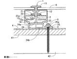
本実施形態の太陽電池モジュール用のフレーム1及び固定部材2を用いた太陽電池モジュールの固定構造は、図1に示すように、フレーム1は所定間隔で野地板41を支持する垂木等の支持部材42の位置にスライド可能とし固定具5(例えば、ビスやボルト等)を介して固定部材2によって完全固定される。支持部材42の延びる方向に配置された二つの太陽電池モジュールの近接するフレーム1同士が互いに接した状態で略同一面状となるように接合される。また、本例では、軒側は太陽電池モジュール(太陽電池アレイとも称す)の意匠性を向上させるための化粧カバー1aが設置されている。
As shown in FIG. 1, the solar cell module fixing structure using the
更に詳しく説明すると、図2及び図4(A)に示すように、太陽電池モジュール用のフレーム1の断面形状は、フレーム1の高さに対して略中間に四角形の底面が来る四角形があり、その右上面の上に配置された一側面側に開口し太陽電池パネル本体におけるモジュールガラス6の辺縁が挿入支持されるコの字状の挿入支持部11を具備し、四角形の右下内部に配置された一側面側とは反対側の他側面側に開口する接合部12を具備する。そして、四角形の一側面側より下側へ延びた後に、他側面側へ延びるL状の底部14がある。更に、接合部12と底部14の中央付近に底部14と同一方向へ延び、先端が上部に突出する鏃状の形状をした鏃状先端部13aを有した係合突部13を具備する。なお、モジュールガラス6の辺縁と挿入支持部11との間には、公知のシール部材が配置されている。
More specifically, as shown in FIG. 2 and FIG. 4 (A), the cross-sectional shape of the
なお、図示するように、フレーム1の他側面側(図4(A)中、右側側面)は、上面から挿入支持部11が形成された部位あたりまでが最も突出し、それよりも下側の接合部12の下部、係合突部13、及び底部14の他側面側端部の突出量が、上記の挿入支持部11が形成された部位よりも一側面側へ控えた状態となっている。これにより、フレーム1の他側面側同士を接合すると、図1に示すように、上面から挿入支持部11が形成された部位あたりまで互いに接した状態となり、それよりも下側では、フレーム1同士の間に隙間が形成されるようになっている。なお、係合突部13の他側面側端部は、底部14よりも更に一側面側へ控えた位置となっている。
As shown in the figure, the other side surface of the frame 1 (the right side surface in FIG. 4 (A)) protrudes most from the upper surface to the portion where the insertion support portion 11 is formed, and the lower side of the joint is connected to the lower side. The amount of protrusion of the lower portion of the
また、図示するように、フレーム1における接合部12の開口側上部には、C面取りが施されており、このC面取りによって、接合部12の開口側上部が傾斜した状態となっている。また、フレーム1における接合部12の開口側下部の先端と、底部14の他側面側の先端とが、夫々互いに向き合う向きに折れ曲がっていると共に、それらの他側面側端部が略同一面状(他側面側の突出量が同じ)となるようになっている。なお、フレーム1には、挿入支持部11と接合部12との間の他側面側の内側と、係合突部13と底部14との間の一側面側の内側に、フレーム1同士を枠状に組立てる際等に用いるビス孔が形成されている。また、フレーム1の材質は、同一断面形状のアルミの押出し材で、色はブラックやシルバー、ブラウン等である。
As shown in the figure, the chamfering is applied to the opening side upper portion of the
更に、本実施例では、図3に示すように、モジュールガラス6におけるフレーム1が固定された一対の対向する辺(軒側と棟側の辺)に対して直交する辺(流れ方向に沿った辺)には、側面フレーム10,10aが固定されており、フレーム1の端部に側面フレーム10,10aがフレーム固定ビス10eによって固定されている。このように、四角形(矩形状)のモジュールガラス6の周辺にフレーム1及び側面フレーム10,10aが固定されることで、四角形の太陽電池モジュールが形成されるようになっている。なお、本例では、フレーム1と側面フレーム10,10aとが、夫々異なる断面形状のものとされている。
Furthermore, in this embodiment, as shown in FIG. 3, the sides (in the flow direction) are orthogonal to a pair of opposing sides (eave side and ridge side) to which the
一方、固定部材2は、フレームの接合部12内に挿入可能とされ互いに離反する方向へ延びるように配置された一対の被接合部21と、一対の被接合部21の略中間より下方へ延びる立下り部22と、立下り部22の下端に配置されフレーム1の底部14を載置可能な台座部24とを具備する。また、被接合部21と台座部上面24aの間で立下り部22より左側へ延び、先端が下部に突出する鏃状の形状をした被鏃状先端部23aを有したフレーム1の係合突部13と係合する被係合部23を具備する。この台座部24は、立下り部22との接点より右下側に四角形があり、左下側に右下側の四角形と略同一の大きさの下側が開口するコの字の形状となっている。また、台座部上面24aは、フレーム1の底部14を載置可能とし、台座部下面24bの下側には、防水と屋根材4の表面の凹凸に対応するための防水ゴム3(例えば、ブチルゴム)が貼られている。更に、台座部下面24aより被係合部23の延びる方向とは反対方向へ延び、支持部材42に固定するための固定部25を具備する。
On the other hand, the fixing
この固定部材2は、一対の被接合部21と立下り部22により略T字状に形成されていると共に、立下り部22の側面に、フレーム1における接合部12の開口側下部の先端、及び底部14の他側面側先端が夫々当接するようになっており、この立下り部22によってフレーム1が他側面側へ移動するのを規制するようになっている。また、被接合部21の先端下側の角部にC面取りが施されており、このC面取りによって被接合部の先端下側が傾斜した状態となっている。なお、固定部材2の材質は、同一断面形状のアルミの押出し材で色はブラックやシルバーである。また、長さは、押出し方向に対して100mm〜200mmが理想であり、フレームよりも短く形成されているためスライド可能となる。
The fixing
また、固定部材2の台座部24の台座部上面24aと台座部下面24bの間で周辺屋根材によって高さの調整をすることができる。例えば、アスファルトシングルやスレート屋根材等のフラットな屋根に対して、モジュール間ケーブル61(図1参照)が通る程度の高さに下げ、屋根材4とフレーム1の底部14の下面までの高さを約7mmとすることができる。また、周辺屋根材が瓦等の厚みのある屋根材4aに対しては、周辺の屋根材4aとフレーム1の上面の高さを略同一高さとすることができるようになっており、高さ調整することで建物との一体感が出て意匠性の向上が図れるようになっている。
Moreover, height adjustment can be carried out with a surrounding roof material between the base part
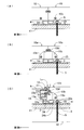
続いて、本実施例における太陽電池モジュール用のフレーム1及び固定部材2を用いた太陽電池モジュールの施工方法について図1乃至図4を基に説明する。まず、図1で示すように、屋根等の支持部材42にまず、固定部材2としてのスターター金具2aを固定し、スターター金具2aの棟側(軒側とは反対側)に一つ目の太陽電池モジュールを配置しこのスターター金具2aに一つ目の太陽電池モジュールの一辺(軒側の辺)のフレーム1を接合する。続いて、スターター金具2aに接合された辺とは反対側の辺(棟側の辺)のフレーム1に対して固定部材2を接合する。その際に、固定部材2の支持部材42に固定する固定部25が接合された太陽電池モジュールとは反対側に向くように、太陽電池モジュールのフレーム1に接合する。そして、フレーム1に対して固定部材2をスライドさせて、所定間隔で野地板41を支持する支持部材42の位置に固定部材2を固定することで一つ目の太陽電池モジュールが支持部材42に固定される。
Then, the construction method of the solar cell module using the
次に一つ目の太陽電池モジュールを固定している固定部材2に対して、その棟側に二つ目の太陽電池モジュールにおける軒側のフレーム1を接続する。これにより、二つの太陽電池モジュールの近接するフレーム1同士が接した状態となると共に、二つ目の太陽電池モジュールの下側で固定部材2が支持部材42に固定された状態となる。その後、二つ目の太陽電池モジュールにおける他方の辺(棟側の辺)のフレーム1に固定部材2を接続し、上記と同様にその固定部材2を支持部材42に固定することで二つ目の太陽電池モジュールが完全に固定されることとなり、上記の作業を繰り返すことで順次太陽電池モジュールを軒側から棟側へ向かって支持部材42に固定することができる。従って、本例の太陽電池モジュールの固定構造によると、支持部材42に対して、或るところ(例えば、スターター金具2a)を基点として複数の太陽電池モジュールを一方から順番に固定することができ、施工の標準化を図ることができ、施工のコストダウンをすることができるようになっている。
Next, the
更に詳しく説明すると、図4(A)で示すように、固定部材2を所定間隔で野地板41を支持する支持部材42のおよその位置に配置し、フレーム1の係合突部13と固定部材2の被係合突部23を利用して係合する。これら係合突部13と被係合突部23とを係合することで、フレーム1の延びる方向に対して直角方向への移動するのを規制することができ、設置時の固定部材2の脱落とスムーズなスライドを可能とすることができ、施工のコストダウンをすることができるようになっている。
More specifically, as shown in FIG. 4A, the fixing
次に、図4(B)で示すように、固定部材2を支持部材42に固定できる位置に置き、台座部下面24bの下にある防水と屋根材4の表面の凹凸に対応するための防水ゴム3の剥離紙(図示せず)を剥がし、所定の位置で固定部材2を屋根材4の表面に設置する。その後、固定部25の固定ビスホール25aを利用して固定具5によって固定部材2を支持部材42に完全固定することで、太陽電池モジュールを支持部材42に固定することができる。これにより、太陽電池モジュールにかかる外力(例えば、風荷重、地震荷重)に対して設置場所より固定部材2が外れることを防ぐことができる。
Next, as shown in FIG. 4B, the fixing
最後に、図4(C)で示すように、固定部材2を支持部材42に固定後、棟側に来る二つ目の太陽電池モジュールにおけるフレーム1の底部14の底部先端部14aを固定部材2の台座部上面24aの上に載せ、軒側へ滑らせながら、固定部材2の被接合部21に対して、フレーム1の接合部12を挿入接合する。この時、固定部材2の二つ目の太陽電池モジュールの載る側の台座部上面24aは、被接合部21の長さより長いため、フレーム1の底部14の底部先端部14aを台座部上面24aに載せ易いようになっている。更に、フレーム1は、接合部12の開口側上部が傾斜していると共に、固定部材2は、被接合部21の先端下側が傾斜しているので、被接合部21に接合部12を接合する際に、太陽電池モジュールを斜めにしても干渉することがなく、斜めにした状態で接合することができるため、施工し易く、施工のコストダウンをすることができるようになっている。
Finally, as shown in FIG. 4C, after fixing the fixing
続いて、図5(A)は、上記した太陽電池モジュールの固定構造を用いて、太陽電池モジュールを屋根材4(例えば、アスファルトシングルやスレート屋根材の様に厚みが薄い屋根材)の上に設置した場合の設置事例である。固定部材2の台座部24の台座部上面24aと台座部下面24bの間で高さの調整をすることができ、モジュール間ケーブルが通る程度の高さに下げ、屋根材4とフレーム1の底部14の下面までの高さを約7mmとすることで、建物との一体感が出て意匠性の向上が図れるようになっている。
Subsequently, FIG. 5A shows that the solar cell module is placed on a roof material 4 (for example, a roof material having a small thickness like asphalt single or slate roof material) by using the fixing structure of the solar cell module described above. This is an installation example when installed. The height can be adjusted between the pedestal portion
また、図5(B)は、上記した太陽電池モジュールの固定構造を用いて、太陽電池モジュールのフレーム1の上面と、周辺屋根材4a(例えば、瓦の様に厚みが厚い屋根材)を略同一高さに納めた場合の設置事例である。上記と同様に、固定部材2の台座部24の台座部上面24aと台座部下面24bの間で高さの調整をすることができ、周辺屋根材が瓦等の厚みのある屋根材4aに対しては、周辺の屋根材4aとフレーム1の上面の高さを略同一高さとすることができるので、建物との一体感が出て意匠性の向上が図れるようになっている。
FIG. 5B is a schematic view of the upper surface of the solar
なお、太陽電池モジュールの固定構造として、図3(B)及び(C)に示すように、側面フレーム10の替りに、両端に固定部材2が通過可能な切欠き部10dが形成された側面フレーム10aを用いると共に、側面フレーム10aを用いた太陽電池モジュール同士を固定部材2で屋根材4に連結固定した状態で、対向する側面フレーム10aの切欠き部10dを覆うように閉鎖する側面キャップ10bを、側面フレーム10aを挟んでフレーム1の端部にフレーム固定ビス10eで固定するようにしても良い。なお、側面キャップ10bは、アルミ材もしくはカラー鋼板(例えば、ガルバリウム鋼板)により形成されていると共に、フレーム1及び側面フレーム10aと同様の色とされている。
As shown in FIGS. 3 (B) and 3 (C), as a fixing structure of the solar cell module, a side frame in which notched
詳しく説明すると、図3(C)に示すように、側面フレーム10aの切欠き部10dの大きさを、固定部材2の被接合部21と被係合突部23との干渉が無い大きさとする共に、側面キャップ10eの大きさを、対向する切欠き部10dを充分に覆うことができる大きさとしている。そして、側面キャップ10bを、二つの太陽電池モジュールに跨るようにフレーム固定ビス10eの一部を利用してフレーム1に留付けている。
More specifically, as shown in FIG. 3C, the size of the notched
この側面フレーム10aの切欠き部10dと、側面キャップ10bとによって、太陽電池モジュールを屋根材4に固定・設置した後で、太陽電池モジュールのメンテナンス時に、側面キャップ10eを外し、フレーム1の係合突部13と固定部材2の被係合突部21の係合機能により太陽電池モジュールを横に(フレーム1の延びる方向に)スライドさせることで、切欠き部10dを通して固定部材2から太陽電池モジュールを外すことができるようになっている。これにより、通常設置時は、側面キャップ10bの設置により、意匠性の向上と太陽電池モジュールが横ずれを起こして落下するのを防止することができると共に、太陽電池モジュールの設置後にメンテナンスをする際は、屋根材4より固定部材2を外さなくても太陽電池モジュールを外すことが可能となり、屋根材4の破壊や漏水の危険性を少なくしてメンテナンスを可能とすることができる。
After fixing and installing the solar cell module on the
このように、本実施形態の太陽電池モジュールの固定構造、太陽電池モジュール用のフレーム1及び固定部材2によると、太陽電池モジュールの固定構造に係る部品点数を削減すると共に施工の標準化が図れるようにすることで、製造及び施工のコストダウンができる他に、意匠性を向上させることができる。
As described above, according to the solar cell module fixing structure, the solar
また、フレーム1に対して固定部材2を自由にスライドすることができるので、固定部材2を所定間隔で野地板41を支持する支持部材42の位置に配置し、固定具5を利用してより強固に太陽電池モジュールを固定することができる。
Further, since the fixing
また、太陽電池モジュールを固定部材2によってフレーム1を介して固定した後に、棟側の太陽電池モジュールのフレーム1を固定部材2によって固定することができる。その際に、固定部材2における支持部材42へ固定する固定部25が棟側の太陽電池モジュールの下側で支持部材42へ固定しているため、フレーム1同士が互いに接した状態にできる。更に、太陽電池モジュール同士が略同一面状となるように接合するので、意匠性が高いため、カバー等の部材を使用しなくてもよい。また、近接する太陽電池モジュールのフレーム1同士を互いに接した状態としているので、同じ大きさの太陽電池モジュールであれば、太陽電池モジュールの設置面積を可能な限り小さくすることができ、屋根等への太陽電池モジュールの設置枚数が減少するのを防止することができる。
Further, after the solar cell module is fixed by the fixing
更に、太陽電池モジュールの対向する二つの辺に、同一断面形状のフレーム1を用いているので、異なる形状のフレーム1を使用しなくても太陽電池モジュールを支持部材に固定することができ、部品点数を削減して太陽電池モジュールの固定構造に係る製造のコストダウンをすることができる。
Furthermore, since the
また、フレーム1にある挿入支持部11と側面フレーム10にある挿入支持部を利用して、以前よりある太陽電池セルを持つモジュールガラス6を挿入支持することができる。
Moreover, the
更に、隣接して配置された太陽電池モジュール同士を側面キャップ10bにより連結することができるので、一方の太陽電池モジュールと隣接する他方の太陽電池モジュールとを、側面キャップ10b及びフレーム固定ビス10eを介して太陽電池モジュール同士を通電可能な状態とすることができ、これにより、太陽電池モジュール間でアースを取る際に、アース用のケーブルを別途取り付けたり、アースを取るための部材を別途用意する必要が無く、簡単に太陽電池モジュール間同士をアース接続することができると共に、アースに係るコストが増加するのを抑制することができる。
Furthermore, since the solar cell modules arranged adjacent to each other can be connected by the
以上、本発明について好適な実施形態を挙げて説明したが、本発明はこれらの実施形態に限定されるものではなく、以下に示すように、本発明の要旨を逸脱しない範囲において、種々の改良および設計の変更が可能である。 The present invention has been described with reference to preferred embodiments. However, the present invention is not limited to these embodiments, and various modifications can be made without departing from the spirit of the present invention as described below. And design changes are possible.
すなわち、本実施形態ではフレーム1の側面フレーム10aを固定するビスホールを兼用して側面キャップ10bを設置するものを示したが、図6(A)乃至(C)に示すように、フレーム1eに側面キャップ用のビスホール14bを設け、側面キャップ10cを側面キャップ固定ビス10fにて側面キャップ10cを留め付けても良い。この側面キャップ10cは、対向する側面フレーム10aの切欠き部10d内に納まる大きさとされ、側面フレーム10aと略同じ高さとなるので意匠性が良い。さらに、メンテナンス時において、フレーム1と側面フレーム10aとを固定するフレーム固定ビス10eを緩めることが無いのでフレームがバラバラになる可能性は無い。なお、側面キャップ固定ビス10fが余分に必要となるが、図6(C)に示すように、フレーム固定ビス10eと側面キャップ固定ビス10fとがはっきりと分かれているのでメンテナンス性がよく、外すビスを間違えることが無くなる。
In other words, in the present embodiment, the
また、フレーム1にある先端が上部に突出する鏃状の形状をした鏃状先端部13aを有した係合突部13と、固定部材2にある先端が下部に突出する鏃状の形状をした被鏃状先端部23aを有したフレーム1の係合突部13と係合する被係合部23としたが、これに限定するものではなく、図7(A)で示すようなL状先端部13bと、被L状先端部23bとしても良い。具体的には、係合突部13のL状先端部13bと、被係合部23の被L状先端部23bとすることにより、鏃状の形状同士より強固に係合することができる。通常の設置では、固定部材2を所定間隔で野地板41を支持する支持部材42のおよその位置に配置し、フレーム1にある係合突部13と固定部材2にある被係合突部23を利用して係合するが、例えば、壁等の垂直に設置する場合、係合突部13と被係合部23にかかる負荷は強くなる。よって、フレーム1bのL状先端部13bと、固定部材2bの被L状先端部23bにすることにより、より強固な係合力を得ることができる。
In addition, the
更に、図7(B)に示すように、フレーム1の底部14の反対側に延びるヒレ部14aを備えたフレーム1cとしても良い。ヒレ部14aを備えることによってフレーム1cは、フレーム1に比べてX方向(支持部材に沿った方向)、Y方向(支持部材に対して直角方向)のたわみに対する強度が共に増すことができる。例えば、多雪地域や強風地域に設置する場合、より強固なフレーム1が必要となる。ヒレ部14aによってフレーム1の補強が可能となる。
Furthermore, as shown in FIG. 7B, a
また、本実施形態では接合部12と底部14の中央付近に底部14と同一方向へ延び、先端が上部に突出する鏃状の形状をした鏃状先端部13aを有した係合突部13と、被接合部21と台座部上面24aの間で立下り部22より左側へ延び、先端が下部に突出する鏃状の形状をした被鏃状先端部23aを有したフレーム1の係合突部13と係合する被係合部23としたが、これに限定するものではなく、図7(C)で示すようなL状先端部13cと、被L状先端部23cとしても良い。具体的には、フレーム1の底部14の先端にL状のL状先端部13cを備え、固定部材2の被係合部23を被L状先端部23cとして係合したものである。これにより、フレーム1のように係合突部13を備える必要がなく、フレーム1dのように底部14と係合突部機能を兼ねることができるので、断面積が減り、フレーム1のコストダウンに繋げることができる。
Further, in the present embodiment, the engaging
1,1b,1c,1d,1e フレーム
2,2b,2c 固定部材
3 防水ゴム
4 屋根材
5 固定具
10,10a 側面フレーム
10b,10c 側面キャップ
11 挿入支持部
12 接合部
13,13b,13c 係合突部
14 底部
21 被接合部
23,23b,23c 被係合突部
24 台座部
25 固定部
42 支持部材
1a 化粧カバー
1, 1b, 1c, 1d,
Claims (8)
前記フレームは、
一側面側に開口し前記太陽電池パネル本体の辺縁が挿入支持される挿入支持部と、該挿入支持部の下側に配置され前記一側面側とは反対側の他側面側に開口する接合部と、該接合部の下側に配置されると共に前記他側面側に開口し上側へ突出する係合突部とを有し、同一断面形状で長尺状に形成され、
前記固定部材は、
前記フレームの前記接合部内に挿入可能とされ互いに離反する方向へ延びるように配置された一対の被接合部と、一対の該被接合部の間から下方へ延びる立下り部と、該立下り部の下端に配置され前記フレームの底部を載置可能な台座部と、該台座部と前記被接合部との間で前記立下り部から前記被接合部の一方と同じ方向へ延び先端に下側へ突出し前記フレームの前記係合突部と係合する被係合突部を備えた係合片と、前記台座部の下面と同一面の下面とされ前記係合片の延びる方向とは反対方向へ延び前記支持部材に固定するための固定部とを有し、同一断面形状で前記フレームよりも短く形成されており、
前記固定部材が前記フレームに対してスライド可能とされ、前記固定部材によって、前記支持部材の延びる方向に配置された二つの前記太陽電池モジュールの近接する前記フレーム同士が互いに接した状態で、前記太陽電池モジュール同士が略同一面状となるように接合すると共に、一方の前記太陽電池モジュールが前記フレームの延びる方向に対して直角方向へ移動するのを規制し、前記固定部材が他方の前記太陽電池モジュールの下側で前記支持部材へ固定されることを特徴とする太陽電池モジュールの固定構造。 A solar cell module comprising a solar cell panel main body having a solar cell and having a polygonal outer shape and a frame fixed to at least a pair of opposing sides around the solar cell main body. Fixing of the solar cell module for fixing the solar cell module to the support member by joining the fixing member to the frame on each of the opposing sides of the battery module and then supporting the fixing member on a predetermined support member Structure,
The frame is
An insertion support portion that opens to one side surface and the edge of the solar cell panel body is inserted and supported, and a joint that is disposed below the insertion support portion and opens to the other side surface opposite to the one side surface side And an engagement protrusion that is disposed on the lower side of the joint and opens to the other side surface and protrudes upward, and is formed in an elongated shape with the same cross-sectional shape,
The fixing member is
A pair of joined parts that can be inserted into the joint part of the frame and arranged to extend away from each other; a falling part that extends downward from between the pair of joined parts; and the falling part A pedestal portion disposed at the lower end of the frame and capable of mounting the bottom portion of the frame, and extending in the same direction as one of the joined portions from the falling portion between the pedestal portion and the joined portion, and lower to the tip An engagement piece having an engaged protrusion that protrudes toward and engages with the engagement protrusion of the frame, and a lower surface that is flush with the lower surface of the pedestal and is opposite to the direction in which the engagement piece extends And a fixing portion for fixing to the support member, and is formed shorter than the frame with the same cross-sectional shape,
The fixing member is slidable with respect to the frame, and in the state where the frames adjacent to each other of the two solar cell modules arranged in the extending direction of the support member are in contact with each other, the solar The battery modules are joined so as to have substantially the same plane, and one of the solar battery modules is restricted from moving in a direction perpendicular to the extending direction of the frame, and the fixing member is the other solar battery. A solar cell module fixing structure, wherein the solar cell module fixing structure is fixed to the support member below the module.
前記固定部材は、前記被接合部の先端下側が傾斜していることを特徴とする請求項1又は請求項2に記載の太陽電池モジュールの固定構造。 The frame has an inclined upper part on the opening side of the joint,
3. The solar cell module fixing structure according to claim 1 , wherein the fixing member is inclined at a lower side of a tip of the bonded portion . 4.
該側面キャップを外すことで、前記固定部材を前記支持部材に支持させた状態で、前記固定部材により固定された前記太陽電池モジュールを、前記フレームの延びる方向へスライドさせて前記固定部材から前記太陽電池モジュールを外せるようにしたことを特徴とする請求項1から請求項3までの何れか一つに記載の太陽電池モジュールの固定構造。 A side frame that is fixed to a side different from the side to which the frame is fixed around the solar cell panel body and has a notch through which the fixing member can be passed at an end, and the notch of the side frame. And further comprising a side cap fixed to the frame.
By removing the side cap, in a state where the fixing member is supported by the support member, the solar cell module fixed by the fixing member is slid in the direction in which the frame extends to move the solar module from the fixing member. The structure for fixing a solar cell module according to any one of claims 1 to 3, wherein the battery module can be removed .
一側面側に開口し前記太陽電池パネル本体の辺縁が挿入支持される挿入支持部と、 An insertion support part that is open on one side surface and the edge of the solar cell panel body is inserted and supported;
該挿入支持部の下側に配置され前記一側面側とは反対側の他側面側に開口し、前記固定部材の前記被接合部が挿入される接合部と、 A joint portion that is disposed below the insertion support portion and that opens to the other side surface opposite to the one side surface side, and into which the joined portion of the fixing member is inserted;
該接合部の下側に配置されると共に前記他側面側に開口し上側へ突出する係合突部と An engaging protrusion that is disposed below the joint and that opens to the other side surface and protrudes upward;
を有し、底部が前記固定部材の前記台座部に載置され、同一断面形状で前記固定部材よりも長尺に形成されていることを特徴とするフレーム。The frame is characterized in that the bottom portion is placed on the pedestal portion of the fixing member and is formed in a longer shape than the fixing member with the same cross-sectional shape.
前記フレームの前記接合部内に挿入可能とされ互いに離反する方向へ延びるように配置された一対の被接合部と、
一対の該被接合部の間から下方へ延びる立下り部と、
該立下り部の下端に配置され前記フレームの底部を載置可能な台座部と、
該台座部と前記被接合部との間で前記立下り部から前記被接合部の一方と同じ方向へ延び先端に下側へ突出し前記フレームの前記係合突部と係合する被係合突部を備えた係合片と、
前記台座部の下面と同一面の下面とされ前記係合片の延びる方向とは反対方向へ延び前記支持部材に固定するための固定部と
を有し、同一断面形状で前記フレームよりも短く形成されていることを特徴とする固定部材。 The solar cell module has solar cells and the outer shape is a polygonal shape and is fixed to at least a pair of opposing sides around the flat plate-shaped solar cell body, and is open to one side and the edge of the solar cell body is An insertion support portion that is inserted and supported; a joint portion that is disposed below the insertion support portion and that opens to the other side surface opposite to the one side surface side; The solar cell module is formed into a predetermined support member through a frame for the solar cell module that has an engagement protrusion that opens to the other side surface and protrudes upward, and is formed in an elongated shape with the same cross-sectional shape. A fixing member for a solar cell module for fixing,
A pair of joints that are insertable into the joints of the frame and arranged to extend away from each other;
A falling part extending downward from between the pair of joined parts;
A pedestal that is placed at the lower end of the falling part and on which the bottom of the frame can be placed;
An engaged projection that extends from the falling portion in the same direction as one of the joined portions between the pedestal portion and the joined portion, protrudes downward at the tip, and engages with the engaging projection of the frame. An engagement piece with a portion;
A fixing portion for fixing to the support member and extending in a direction opposite to a direction in which the engagement piece extends;
A fixing member having the same cross-sectional shape and shorter than the frame.
前記台座部が、前記接合部の延びる長さよりも長く延びていることを特徴とする請求項6に記載の固定部材。 The fixing member is
The fixing member according to claim 6, wherein the pedestal portion extends longer than a length in which the joint portion extends .
前記台座部が、前記フレームの下面と前記支持部材との間で、前記太陽電池パネル本体に接続されるモジュール間ケーブルを通過可能な隙間を形成することができる高さであり、
前記太陽電池モジュール本体の上面が、前記支持部材上に載置される屋根材と略同じ高さとなる高さまでの調節を可能とすることを特徴とする請求項6又は請求項7に記載の固定部材。 The fixing member is
The pedestal is a height that can form a gap between the lower surface of the frame and the support member that can pass through an inter-module cable connected to the solar cell panel body,
8. The fixing according to claim 6, wherein the solar cell module main body can be adjusted to a height at which the upper surface of the solar cell module main body is substantially the same height as the roof material placed on the support member. Element.
Priority Applications (7)
| Application Number | Priority Date | Filing Date | Title |
|---|---|---|---|
| JP2007153463A JP4290750B2 (en) | 2007-06-11 | 2007-06-11 | Solar cell module fixing structure, solar cell module frame and fixing member |
| CN2007800512953A CN101802324B (en) | 2007-06-11 | 2007-09-26 | Fixing structure of solar battery module, frame for the solar battery module, and fixing member |
| AU2007355014A AU2007355014B2 (en) | 2007-06-11 | 2007-09-26 | Fixing structure of solar battery module, frame for the solar battery module, and fixing member |
| EP07828390.0A EP2169139B1 (en) | 2007-06-11 | 2007-09-26 | Fixing structure of solar battery module, frame for the solar battery module, and fixing member |
| PCT/JP2007/068617 WO2008152748A1 (en) | 2007-06-11 | 2007-09-26 | Fixing structure of solar battery module, frame for the solar battery module, and fixing member |
| KR1020097014584A KR101355881B1 (en) | 2007-06-11 | 2007-09-26 | Fixing structure of solar battery module, frame for the solar battery module, and fixing member |
| US11/972,193 US7956280B2 (en) | 2007-06-11 | 2008-01-10 | Solar cell module retaining structure, frame for solar cell module, and holding member for solar cell module |
Applications Claiming Priority (1)
| Application Number | Priority Date | Filing Date | Title |
|---|---|---|---|
| JP2007153463A JP4290750B2 (en) | 2007-06-11 | 2007-06-11 | Solar cell module fixing structure, solar cell module frame and fixing member |
Publications (3)
| Publication Number | Publication Date |
|---|---|
| JP2008303660A JP2008303660A (en) | 2008-12-18 |
| JP2008303660A5 JP2008303660A5 (en) | 2009-04-09 |
| JP4290750B2 true JP4290750B2 (en) | 2009-07-08 |
Family
ID=40094740
Family Applications (1)
| Application Number | Title | Priority Date | Filing Date |
|---|---|---|---|
| JP2007153463A Active JP4290750B2 (en) | 2007-06-11 | 2007-06-11 | Solar cell module fixing structure, solar cell module frame and fixing member |
Country Status (7)
| Country | Link |
|---|---|
| US (1) | US7956280B2 (en) |
| EP (1) | EP2169139B1 (en) |
| JP (1) | JP4290750B2 (en) |
| KR (1) | KR101355881B1 (en) |
| CN (1) | CN101802324B (en) |
| AU (1) | AU2007355014B2 (en) |
| WO (1) | WO2008152748A1 (en) |
Families Citing this family (144)
| Publication number | Priority date | Publication date | Assignee | Title |
|---|---|---|---|---|
| JP4684874B2 (en) * | 2005-12-13 | 2011-05-18 | 株式会社屋根技術研究所 | Solar cell module frame |
| EP2008343B1 (en) * | 2006-03-09 | 2017-08-09 | SunPower Corporation, Systems | Photovoltaic module mounting clip with integral grounding |
| CA2681970C (en) * | 2007-03-30 | 2013-09-24 | Haticon Gmbh | Fixture for solar modules |
| WO2008157201A2 (en) * | 2007-06-19 | 2008-12-24 | Bp Corporation North America Inc. | Solar module with a frame for mounting a solar panel |
| JP2009164434A (en) * | 2008-01-08 | 2009-07-23 | Sharp Corp | Solar cell module |
| WO2009129293A2 (en) * | 2008-04-15 | 2009-10-22 | The Penn State Research Foundation | Transparent sustainable wall system |
| KR100921658B1 (en) * | 2008-10-06 | 2009-10-15 | 한국철강 주식회사 | Solar cell module |
| CN102245979A (en) * | 2008-10-11 | 2011-11-16 | 美国太阳能股份有限公司 | Efficient installation solar panel systems |
| FR2938566B1 (en) * | 2008-11-17 | 2012-01-13 | Alain Poivet | DEVICE FOR SUPPORTING PHOTOVOLTAIC CELL PANELS AND SYSTEM FOR SUPPORTING PHOTOVOLTAIC PANELS |
| US11063553B2 (en) | 2008-11-17 | 2021-07-13 | Kbfx Llc | Solar carports, solar-tracking carports, and methods |
| US10277159B2 (en) | 2008-11-17 | 2019-04-30 | Kbfx Llc | Finished multi-sensor units |
| FR2940884B1 (en) * | 2009-01-09 | 2010-12-24 | Jean Paul Pierre Marie Guiol | SYSTEM FOR FIXING PHOTOVOLTAIC SOLAR PANELS ON AGRICULTURAL, HORTICULTURAL, TUNNEL ARBORICOLUS, MULTI-CHAPEL CHAPELS IN PLASTIC COVER OR GLASS. |
| EP2379598B1 (en) * | 2009-01-19 | 2015-03-11 | Innate Pharma | Anti-kir3d antibodies |
| DE202009001098U1 (en) * | 2009-01-27 | 2009-04-30 | Mounting Systems Gmbh | Solar module mounting |
| US10151114B2 (en) | 2010-01-25 | 2018-12-11 | Rillito River Solar, Llc | Roof mount assembly |
| US8826618B2 (en) | 2011-03-15 | 2014-09-09 | Vermont Slate & Copper Services, Inc. | Roof mount assembly |
| US8153700B2 (en) | 2010-03-19 | 2012-04-10 | Vermont Slate & Copper Services, Inc. | Roofing system and method |
| US8209914B2 (en) | 2010-01-25 | 2012-07-03 | Vermont Slate & Copper Services, Inc. | Roofing grommet forming a seal between a roof-mounted structure and a roof |
| US9447988B2 (en) | 2010-01-25 | 2016-09-20 | Rillito Rive Solar, LLC | Roof mount assembly |
| US9134044B2 (en) | 2010-01-25 | 2015-09-15 | Vermont Slate & Copper Services, Inc. | Roof mount assembly |
| DE102009010225A1 (en) * | 2009-02-23 | 2010-09-02 | Solon Se | Solar system of at least one solar module with a resilient mounting of the cover plate |
| US8256169B2 (en) | 2009-03-20 | 2012-09-04 | Northern States Metals Company | Support system for solar panels |
| US8240109B2 (en) * | 2009-03-20 | 2012-08-14 | Northern States Metals Company | Support system for solar panels |
| US8316590B2 (en) * | 2009-03-20 | 2012-11-27 | Northern States Metals Company | Support system for solar panels |
| US20110220596A1 (en) * | 2009-03-20 | 2011-09-15 | Northern States Metals Company | Support system for solar panels |
| CA2756664A1 (en) * | 2009-03-24 | 2010-09-30 | Certainteed Corporation | Photovoltaic systems, methods for installing photovoltaic systems, and kits for installing photovoltaic systems |
| JP4465406B1 (en) * | 2009-04-16 | 2010-05-19 | 株式会社屋根技術研究所 | Connecting member |
| JP4365450B1 (en) * | 2009-05-01 | 2009-11-18 | 株式会社屋根技術研究所 | Solar cell module fixing structure, solar cell module frame and fixing member |
| US8690110B2 (en) * | 2009-05-25 | 2014-04-08 | Solaredge Technologies Ltd. | Bracket for connection of a junction box to photovoltaic panels |
| DE202009007526U1 (en) * | 2009-05-27 | 2009-08-20 | Schletter Gmbh | Device for fastening a mounting rail to a threaded shaft |
| DE202009008931U1 (en) * | 2009-06-29 | 2009-09-24 | Meinhardt, Dirk | Building shell with solar collector module (s) and mounting system therefor |
| US9518596B2 (en) | 2009-07-02 | 2016-12-13 | Solarcity Corporation | Pivot-fit frame, system and method for photovoltaic modules |
| US8919053B2 (en) * | 2009-07-02 | 2014-12-30 | Zep Solar, Llc | Leveling foot apparatus, system, and method for photovoltaic arrays |
| US20120298817A1 (en) * | 2009-07-02 | 2012-11-29 | John Raymond West | Pivot-Fit Frame, System and Method for Photovoltaic Arrays |
| DE202010000293U1 (en) * | 2009-10-09 | 2010-05-20 | Galaxy-Energy Gmbh | Solar roof arrangement |
| ITMI20092031A1 (en) * | 2009-11-18 | 2011-05-19 | Bm S P A | SUPPORT AND AID DEVICE FOR FASTENING OF SOLAR AND SIMILAR PANELS |
| FR2953237B1 (en) * | 2009-12-01 | 2012-04-06 | Jean Pierre Parneix | FRAMING DEVICE COMPRISING A PLURALITY OF PANELS AND FIXING PROFILES ON A SUPPORT STRUCTURE FORMING A SEALED COVERING ELEMENT |
| JP4688951B1 (en) * | 2009-12-25 | 2011-05-25 | シャープ株式会社 | Structure installation stand, structure installation support, and solar power generation system |
| KR20120110104A (en) * | 2009-12-25 | 2012-10-09 | 가부시키가이샤 야네기주쓰켄큐조 | Auxiliary member |
| US10472828B2 (en) | 2010-01-25 | 2019-11-12 | EcoFasten Solar, LLC | Roof mounting system |
| US20110209422A1 (en) * | 2010-02-18 | 2011-09-01 | King Zachary A | Method and apparatus for mounting photovoltaic modules to shingled surfaces |
| FR2964129A1 (en) * | 2010-02-25 | 2012-03-02 | Dome Solar | Device for integrating photovoltaic solar panel on low slope roof of building for electric energy production system, has parts that are positioned one on another by sticking of one of parts to nose of spacer |
| US8595996B2 (en) * | 2010-02-26 | 2013-12-03 | General Electric Company | Photovoltaic framed module array mount utilizing asymmetric rail |
| US10054336B2 (en) * | 2010-03-03 | 2018-08-21 | Robert M. M. Haddock | Photovoltaic module mounting assembly |
| US8181402B2 (en) * | 2010-04-01 | 2012-05-22 | Yanegijutsukenkyujo Co., Ltd. | Building-integrated photovoltaic power unit |
| US8424256B2 (en) * | 2010-04-01 | 2013-04-23 | Thomas Lawson Cook | Asphalt roof integrated photovoltaic |
| US8495839B2 (en) * | 2010-04-01 | 2013-07-30 | Yanegijutsukenkyujo Co., Ltd. | Installation structure of solar cell module |
| DE202010006442U1 (en) * | 2010-05-04 | 2010-08-19 | Ideematec Deutschland Gmbh | Frame for fixing solar modules |
| WO2011154019A1 (en) * | 2010-06-08 | 2011-12-15 | Renusol Gmbh | Mounting system for solar panels and fastening device |
| KR101122601B1 (en) * | 2010-06-29 | 2012-03-16 | 수림금속 주식회사 | Frame for solar module |
| US9816731B2 (en) | 2010-07-02 | 2017-11-14 | Solarcity Corporation | Pivot-fit connection apparatus and system for photovoltaic arrays |
| USD759464S1 (en) | 2010-07-02 | 2016-06-21 | Solarcity Corporation | Leveling foot |
| JP5501125B2 (en) * | 2010-07-06 | 2014-05-21 | 株式会社屋根技術研究所 | Fixed member |
| US8418983B2 (en) | 2010-07-29 | 2013-04-16 | First Solar, Inc. | Slider clip and photovoltaic structure mounting system |
| JP5611716B2 (en) | 2010-08-16 | 2014-10-22 | 株式会社屋根技術研究所 | Plate module fixing structure |
| DE102010040124A1 (en) * | 2010-09-01 | 2012-03-01 | Mounting Systems Gmbh | Profile rail, holding element and thus formed solar module assembly, in particular for a transverse mounting of solar modules |
| US20120073630A1 (en) * | 2010-09-28 | 2012-03-29 | Perfect Source Technology Corp. | Rectangular protective frame for solar cell module |
| US20120097807A1 (en) * | 2010-10-25 | 2012-04-26 | Rees Kyle J | Solar panel support system |
| WO2012079061A1 (en) | 2010-12-09 | 2012-06-14 | Zep Solar, Inc. | Skirt for photovoltaic arrays |
| US20160305459A1 (en) | 2010-12-10 | 2016-10-20 | Solar Clam-P | Panel Mounting System and Method |
| US8763322B2 (en) * | 2010-12-22 | 2014-07-01 | Nissei Kinzoku Co., Ltd. | Solar battery module fixture |
| US8701361B2 (en) * | 2011-01-12 | 2014-04-22 | Pierino Ferrara | Rooftop system with integrated photovoltaic modules and method for constructing the same |
| US8839573B2 (en) | 2011-02-11 | 2014-09-23 | Northern States Metals Company | Spring clip |
| US9611652B2 (en) | 2011-02-25 | 2017-04-04 | Dustin M. M. Haddock | Mounting device for building surfaces having elongated mounting slot |
| JP2012202132A (en) * | 2011-03-25 | 2012-10-22 | Noritz Corp | Fixing structure of solar battery panel |
| US8631629B1 (en) | 2011-03-30 | 2014-01-21 | Gregory M. Wiener | Roof mounting assembly |
| US8448407B1 (en) | 2011-03-30 | 2013-05-28 | Gregory M. Wiener | Roof mounting assembly |
| US10041693B2 (en) * | 2011-03-30 | 2018-08-07 | Daniel Joseph Rheaume | Solar-powered ridge vent fan unit |
| US8776454B2 (en) | 2011-04-05 | 2014-07-15 | Michael Zuritis | Solar array support structure, mounting rail and method of installation thereof |
| CA2739766C (en) * | 2011-05-10 | 2016-08-23 | Robert Richardson | Roof solar panel for conventional sloping roof and shingle integration |
| EP2716835B1 (en) * | 2011-06-03 | 2017-07-12 | Kyocera Corporation | Solar cell array |
| US8683751B2 (en) | 2011-07-08 | 2014-04-01 | Vermont Slate & Copper Services, Inc. | Roof mount having built-in failure |
| CN102299186B (en) * | 2011-08-25 | 2013-06-26 | 浙江正泰太阳能科技有限公司 | Solar cell panel installation and fixing device, and installation and fixing method |
| US10008974B2 (en) | 2011-09-02 | 2018-06-26 | Pv Solutions, Llc | Mounting system for photovoltaic arrays |
| EP2751847B1 (en) * | 2011-09-02 | 2019-03-27 | PV Solutions, LLC | Mounting system for photovoltaic arrays |
| WO2013033687A1 (en) | 2011-09-02 | 2013-03-07 | Rtetta Holdings, Llc | System for tracking and allocating renewable energy contributions to a modular renewable energy system |
| US11022343B2 (en) | 2011-09-02 | 2021-06-01 | Pv Solutions, Llc | Mounting system for photovoltaic arrays |
| US9212833B2 (en) | 2011-09-23 | 2015-12-15 | Vermont Slate and Copper Services, Inc. | Power grip button |
| WO2013043816A1 (en) | 2011-09-23 | 2013-03-28 | Vermont Slate & Copper Services, Inc. | Roof mount assembly and method of mounting same |
| US9038329B2 (en) * | 2011-10-11 | 2015-05-26 | Sunlink Corporation | Structure following roof mounted photovoltaic system |
| USD765591S1 (en) | 2011-12-09 | 2016-09-06 | Solarcity Corporation | Panel skirt and photovoltaic panel |
| EP2604949A1 (en) * | 2011-12-14 | 2013-06-19 | Renusol GmbH | Holding device for fixing a photovoltaic module to a fitting rail |
| US20130168525A1 (en) | 2011-12-29 | 2013-07-04 | Dustin M.M. Haddock | Mounting device for nail strip panels |
| CA2800423A1 (en) * | 2012-01-03 | 2013-07-03 | Certainteed Corporation | Photovoltaic roofing elements and photovoltaic roofing systems |
| KR101198702B1 (en) * | 2012-02-28 | 2012-11-12 | 주식회사 톱텍 | An apparatus for fixing solar module |
| US8505864B1 (en) * | 2012-02-29 | 2013-08-13 | Imp Inc. | PV kit for roof assembly |
| US8640402B1 (en) * | 2012-03-08 | 2014-02-04 | Henry H. Bilge | Building roof fascia, coping and/or solar panel connector arrangement |
| JP5917210B2 (en) * | 2012-03-15 | 2016-05-11 | 本田技研工業株式会社 | Solar cell module fixing method and maintenance method |
| US20150122333A1 (en) * | 2012-05-11 | 2015-05-07 | Kyocera Corporation | Photovoltaic system |
| CN102777454B (en) | 2012-06-28 | 2014-10-01 | 友达光电股份有限公司 | Solar device and fastening mechanism thereof |
| US9320926B2 (en) | 2012-06-28 | 2016-04-26 | Solarcity Corporation | Solar panel fire skirt |
| US8567134B1 (en) * | 2012-06-29 | 2013-10-29 | Sunpower Corporation | Snap-in and progressive locking photovoltaic module |
| US8875401B2 (en) * | 2012-07-18 | 2014-11-04 | Solarcity Corporation | Solar panel clamp system |
| JP5705380B2 (en) * | 2012-07-23 | 2015-04-22 | 株式会社屋根技術研究所 | Solar cell module fixing structure |
| JP5540045B2 (en) * | 2012-07-27 | 2014-07-02 | 株式会社サニックス | Mounting structure of solar cell module |
| CN102810582B (en) * | 2012-08-14 | 2015-04-22 | 友达光电股份有限公司 | Solar device and framework assembly thereof |
| US8740163B1 (en) * | 2012-10-31 | 2014-06-03 | Innovative Medical Products Inc. | Insulated connector for attaching a solar unit to a roof |
| KR101306909B1 (en) * | 2012-11-12 | 2013-09-10 | 두원산업(주) | Support for solar cell module |
| DE102012022738A1 (en) * | 2012-11-21 | 2014-05-22 | Adensis Gmbh | Method for assembling photo-voltaic (PV) modules in PV generator, involves establishing connection between PV module and support structure by using connecting elements provided in rear surface of PV module and support structure |
| KR20140082900A (en) * | 2012-12-24 | 2014-07-03 | 삼성에스디아이 주식회사 | Apparatus for photovoltaic power generation |
| KR101474526B1 (en) * | 2013-02-21 | 2014-12-22 | (주)제이텍 | Pipe support unit for greenhouse |
| WO2014134191A1 (en) * | 2013-02-26 | 2014-09-04 | Zep Solar, Inc. | Torque tube mounted photovoltaic apparatus, system, and method |
| US9303663B2 (en) | 2013-04-11 | 2016-04-05 | Northern States Metals Company | Locking rail alignment system |
| KR101368923B1 (en) * | 2013-04-24 | 2014-03-04 | (주)에이비엠그린텍 | A roof panel which using photovoltanic modules as a closing means |
| US10256765B2 (en) | 2013-06-13 | 2019-04-09 | Building Materials Investment Corporation | Roof integrated photovoltaic system |
| CN104282791A (en) * | 2013-07-10 | 2015-01-14 | 国电光伏有限公司 | Efficient solar cell |
| US9080792B2 (en) * | 2013-07-31 | 2015-07-14 | Ironridge, Inc. | Method and apparatus for mounting solar panels |
| KR20150041932A (en) * | 2013-10-10 | 2015-04-20 | 엘지이노텍 주식회사 | Solar cell module |
| US9397605B2 (en) * | 2013-10-30 | 2016-07-19 | Kevin Stapleton | Panel mounting bracket with under-mounting clamp and related methods |
| EP3128098B1 (en) * | 2014-03-31 | 2018-12-26 | Panasonic Intellectual Property Management Co., Ltd. | Solar cell apparatus |
| WO2016123357A2 (en) | 2015-01-28 | 2016-08-04 | Pv Solutions, Llc | Integrated electrical and mechanical photovoltaic array interconnection system |
| US11817818B2 (en) * | 2015-07-24 | 2023-11-14 | Tecsi Solar, Inc. | Module frame with cable management flange |
| US20170053043A1 (en) * | 2015-08-21 | 2017-02-23 | Solarcity Corporation | Systems and methods for locating structures for rooftop solar panel installation |
| GB2541927A (en) * | 2015-09-04 | 2017-03-08 | Viridian Concepts Ltd | Photovoltaic roof covering |
| US10088201B2 (en) * | 2015-10-09 | 2018-10-02 | Pegasus Solar Inc. | Support assemblies for solar energy panels |
| CN105897134A (en) * | 2016-06-22 | 2016-08-24 | 上海欣美雅节能环境科技有限公司 | Roof with solar cell assembly |
| CN105958926B (en) * | 2016-06-30 | 2018-09-07 | 苏州泽海电子塑胶有限公司 | A kind of rotatable swing fixing bracket of solar panel |
| CN105932943B (en) * | 2016-06-30 | 2018-09-07 | 苏州泽海电子塑胶有限公司 | The rotatable swing fixing bracket of solar panel |
| WO2018023016A1 (en) | 2016-07-29 | 2018-02-01 | Haddock Dustin M M | Trapezoidal rib mounting bracket with flexible legs |
| US10998847B2 (en) | 2016-08-23 | 2021-05-04 | Pegasus Solar Inc. | Solar mounting assemblies |
| JP6775126B2 (en) * | 2016-09-30 | 2020-10-28 | パナソニックIpマネジメント株式会社 | Solar power generator |
| US10630229B2 (en) * | 2016-10-11 | 2020-04-21 | Kevin Stapleton | Panel mounting bracket with grounding mid-clamp and related methods |
| WO2018081722A1 (en) | 2016-10-31 | 2018-05-03 | Haddock Dustin M M | Metal panel electrical bonding clip |
| KR102281392B1 (en) * | 2016-12-31 | 2021-07-26 | 전금옥 | Sola module frame |
| CN106788152B (en) * | 2017-01-04 | 2018-09-28 | 海宁创源太阳能科技有限公司 | A kind of solar panel mounting fixing parts |
| CN106760678A (en) * | 2017-02-13 | 2017-05-31 | 深圳市华人世纪科技有限公司 | Multifunctional bus station booth |
| US10205419B2 (en) * | 2017-03-30 | 2019-02-12 | Sunrun South Llc | Railless solar module installation systems and devices |
| US10177704B2 (en) * | 2017-04-26 | 2019-01-08 | Sunpower Corporation | Snap-on rail assembly |
| US10505493B2 (en) | 2017-07-18 | 2019-12-10 | Tesla, Inc. | Building integrated photovoltaic tile mounting system |
| US11774143B2 (en) | 2017-10-09 | 2023-10-03 | Rmh Tech Llc | Rail assembly with invertible side-mount adapter for direct and indirect mounting applications |
| CN107819426A (en) * | 2017-10-12 | 2018-03-20 | 山东新华联智能光伏有限公司 | Photovoltaic system |
| CN111295488B (en) * | 2017-10-31 | 2021-07-13 | 京瓷株式会社 | Solar cell device |
| CN107986194A (en) * | 2017-12-06 | 2018-05-04 | 安徽宇锋仓储设备有限公司 | A kind of solar-electricity electrical forklift |
| CN108063584B (en) * | 2017-12-22 | 2023-11-14 | 广东南控电力有限公司 | Self-weight photovoltaic system capable of being installed rapidly |
| NZ768908A (en) | 2018-03-21 | 2021-07-30 | Rmh Tech Llc | Pv module mounting assembly with clamp/standoff arrangement |
| WO2020124011A1 (en) | 2018-12-14 | 2020-06-18 | Rmh Tech Llc | Mounting device for nail strip panels |
| EP3997393A1 (en) * | 2019-06-21 | 2022-05-18 | Energy Team B.V. | Self-supporting solar panel assembly, set of at least one self- supporting solar panel assembly and a plurality of fastening elements, roof on which such a set is arranged, and method for mounting solar panels on a roof |
| NL2023965B1 (en) * | 2019-06-21 | 2021-01-25 | Energy Team B V | SOLAR PANEL ASSEMBLY, SET OF AT LEAST ONE SOLAR PANEL ASSEMBLY AND SOME MOUNTING ELEMENTS, ROOF TO WHICH SUCH A SET IS FITTED, AND PROCEDURE FOR MOUNTING SOLAR PANELS ON A ROOF |
| US20210210936A1 (en) * | 2020-01-07 | 2021-07-08 | Samuel Marcus-Flack Truthseeker | Insertion tool for use with solar cable management cavity |
| AU2021239839A1 (en) | 2020-03-16 | 2022-10-06 | Rmh Tech Llc | Mounting device for a metal roof |
| US11041310B1 (en) | 2020-03-17 | 2021-06-22 | Rmh Tech Llc | Mounting device for controlling uplift of a metal roof |
| WO2021202327A1 (en) | 2020-03-30 | 2021-10-07 | Building Materials Investment Corporation | Interlocking laminated structural roofing panels |
| US11855580B2 (en) | 2020-11-09 | 2023-12-26 | Bmic Llc | Interlocking structural roofing panels with integrated solar panels |
| US11757400B1 (en) | 2023-03-15 | 2023-09-12 | Sunmodo Corporation | Devices for mounting solar PV panels to roofs and other mounting structures |
Family Cites Families (15)
| Publication number | Priority date | Publication date | Assignee | Title |
|---|---|---|---|---|
| AU661184B2 (en) * | 1992-09-07 | 1995-07-13 | Hirai Engineering Corporation | Roof apparatus |
| JP3220934B2 (en) * | 1996-07-17 | 2001-10-22 | キヤノン株式会社 | Hybrid panel using solar cell module |
| US6182403B1 (en) * | 1996-08-30 | 2001-02-06 | Canon Kabushiki Kaisha | Combination solar battery and roof unit and mounting method thereof |
| JP3475781B2 (en) * | 1997-09-24 | 2003-12-08 | 松下電工株式会社 | Photovoltaic module mounting rail |
| JP3395597B2 (en) * | 1997-09-24 | 2003-04-14 | 松下電工株式会社 | Solar cell frame |
| US6105317A (en) * | 1997-09-24 | 2000-08-22 | Matsushita Electric Works, Ltd. | Mounting system for installing an array of solar battery modules of a panel-like configuration on a roof |
| JPH11117479A (en) * | 1997-10-08 | 1999-04-27 | Msk:Kk | Fitting structure for solar battery module |
| JP3647312B2 (en) * | 1998-05-20 | 2005-05-11 | キヤノン株式会社 | Solar power generation structure |
| JP3652165B2 (en) | 1999-04-14 | 2005-05-25 | シャープ株式会社 | Solar cell module mounting structure and mounting method thereof |
| US6570084B2 (en) * | 2001-07-10 | 2003-05-27 | Powerlight Corporation | Pressure equalizing photovoltaic assembly and method |
| JP4698089B2 (en) * | 2001-08-20 | 2011-06-08 | 京セラ株式会社 | Solar energy utilization array |
| JP3869292B2 (en) * | 2002-03-26 | 2007-01-17 | 株式会社Msk | Support bracket for solar panel mounting |
| JP2003279333A (en) * | 2002-03-26 | 2003-10-02 | Toshiba Eng Co Ltd | Shape measuring apparatus, appearance examining apparatus, dimension examining apparatus, volume examining apparatus and displacement and deformation measuring apparatus |
| JP2003336357A (en) | 2002-05-20 | 2003-11-28 | Sekisui Chem Co Ltd | Attaching construction for solar energy collecting device |
| JP3455210B1 (en) * | 2002-06-07 | 2003-10-14 | 株式会社栄信 | Mounting frame for solar cell panel and method of assembling the same |
-
2007
- 2007-06-11 JP JP2007153463A patent/JP4290750B2/en active Active
- 2007-09-26 WO PCT/JP2007/068617 patent/WO2008152748A1/en active Search and Examination
- 2007-09-26 AU AU2007355014A patent/AU2007355014B2/en not_active Ceased
- 2007-09-26 CN CN2007800512953A patent/CN101802324B/en not_active Expired - Fee Related
- 2007-09-26 EP EP07828390.0A patent/EP2169139B1/en not_active Not-in-force
- 2007-09-26 KR KR1020097014584A patent/KR101355881B1/en not_active IP Right Cessation
-
2008
- 2008-01-10 US US11/972,193 patent/US7956280B2/en active Active
Also Published As
| Publication number | Publication date |
|---|---|
| EP2169139A4 (en) | 2010-12-08 |
| KR101355881B1 (en) | 2014-01-28 |
| EP2169139B1 (en) | 2016-01-27 |
| US20080302407A1 (en) | 2008-12-11 |
| KR20100037020A (en) | 2010-04-08 |
| CN101802324B (en) | 2011-09-21 |
| CN101802324A (en) | 2010-08-11 |
| US7956280B2 (en) | 2011-06-07 |
| WO2008152748A1 (en) | 2008-12-18 |
| JP2008303660A (en) | 2008-12-18 |
| AU2007355014B2 (en) | 2014-01-23 |
| EP2169139A1 (en) | 2010-03-31 |
| AU2007355014A1 (en) | 2008-12-18 |
Similar Documents
| Publication | Publication Date | Title |
|---|---|---|
| JP4290750B2 (en) | Solar cell module fixing structure, solar cell module frame and fixing member | |
| JP4365450B1 (en) | Solar cell module fixing structure, solar cell module frame and fixing member | |
| KR101219555B1 (en) | Frame body for solar cell module | |
| JP4365449B2 (en) | Solar cell module construction method | |
| JP4679482B2 (en) | Solar cell module fixing member and solar cell module fixing structure | |
| JP5025125B2 (en) | Frame for solar-powered equipment and installation method of solar-powered equipment using the same | |
| JP5528398B2 (en) | Solar cell module | |
| JP3652165B2 (en) | Solar cell module mounting structure and mounting method thereof | |
| JPH0988280A (en) | Fitting structure of solar cell panel | |
| JP4093839B2 (en) | Roof mounting structure for solar cell module and solar cell array | |
| JP4448190B2 (en) | Fixing member for solar cell module | |
| CN113482253A (en) | Support for photovoltaic building integrated roof | |
| CN216196119U (en) | Photovoltaic building integrated roof | |
| CN216196120U (en) | Support for photovoltaic building integrated roof | |
| JP4679447B2 (en) | Roofing rail | |
| JP4125336B2 (en) | Solar cell module mounting cover | |
| JP4991119B2 (en) | Solar cell module device | |
| JP2017101517A (en) | Solar cell module mounting fixture, and solar power generation device | |
| JP3392782B2 (en) | Solar energy module, its connection structure and house | |
| WO2022081689A1 (en) | Solar cell roof | |
| JP4450679B2 (en) | Solar cell module construction method | |
| JP2006177001A (en) | Mounting structure of roof-material integral type solar-cell module | |
| JP2012229518A (en) | Connection metal fitting for connecting roof tile and solar cell module | |
| JP2012102543A (en) | Installation structure of solar cell module on batten seam roof | |
| JPH07229258A (en) | Roof panel, roof structure, and construction method for roof |
Legal Events
| Date | Code | Title | Description |
|---|---|---|---|
| A521 | Request for written amendment filed |
Free format text: JAPANESE INTERMEDIATE CODE: A523 Effective date: 20090223 |
|
| A621 | Written request for application examination |
Free format text: JAPANESE INTERMEDIATE CODE: A621 Effective date: 20090223 |
|
| A871 | Explanation of circumstances concerning accelerated examination |
Free format text: JAPANESE INTERMEDIATE CODE: A871 Effective date: 20090223 |
|
| TRDD | Decision of grant or rejection written | ||
| A975 | Report on accelerated examination |
Free format text: JAPANESE INTERMEDIATE CODE: A971005 Effective date: 20090311 |
|
| A01 | Written decision to grant a patent or to grant a registration (utility model) |
Free format text: JAPANESE INTERMEDIATE CODE: A01 Effective date: 20090324 |
|
| A01 | Written decision to grant a patent or to grant a registration (utility model) |
Free format text: JAPANESE INTERMEDIATE CODE: A01 |
|
| A61 | First payment of annual fees (during grant procedure) |
Free format text: JAPANESE INTERMEDIATE CODE: A61 Effective date: 20090401 |
|
| R150 | Certificate of patent or registration of utility model |
Ref document number: 4290750 Country of ref document: JP Free format text: JAPANESE INTERMEDIATE CODE: R150 Free format text: JAPANESE INTERMEDIATE CODE: R150 |
|
| FPAY | Renewal fee payment (event date is renewal date of database) |
Free format text: PAYMENT UNTIL: 20120410 Year of fee payment: 3 |
|
| FPAY | Renewal fee payment (event date is renewal date of database) |
Free format text: PAYMENT UNTIL: 20150410 Year of fee payment: 6 |
|
| R250 | Receipt of annual fees |
Free format text: JAPANESE INTERMEDIATE CODE: R250 |
|
| S531 | Written request for registration of change of domicile |
Free format text: JAPANESE INTERMEDIATE CODE: R313531 |
|
| R350 | Written notification of registration of transfer |
Free format text: JAPANESE INTERMEDIATE CODE: R350 |
|
| R250 | Receipt of annual fees |
Free format text: JAPANESE INTERMEDIATE CODE: R250 |
|
| R250 | Receipt of annual fees |
Free format text: JAPANESE INTERMEDIATE CODE: R250 |
|
| R250 | Receipt of annual fees |
Free format text: JAPANESE INTERMEDIATE CODE: R250 |
|
| R250 | Receipt of annual fees |
Free format text: JAPANESE INTERMEDIATE CODE: R250 |