JP4289613B2 - Low melting point metal alloy forming method - Google Patents
Low melting point metal alloy forming method Download PDFInfo
- Publication number
- JP4289613B2 JP4289613B2 JP2004055055A JP2004055055A JP4289613B2 JP 4289613 B2 JP4289613 B2 JP 4289613B2 JP 2004055055 A JP2004055055 A JP 2004055055A JP 2004055055 A JP2004055055 A JP 2004055055A JP 4289613 B2 JP4289613 B2 JP 4289613B2
- Authority
- JP
- Japan
- Prior art keywords
- solid
- temperature
- molding
- heating
- holding cylinder
- Prior art date
- Legal status (The legal status is an assumption and is not a legal conclusion. Google has not performed a legal analysis and makes no representation as to the accuracy of the status listed.)
- Expired - Fee Related
Links
Images

Classifications
-
- B—PERFORMING OPERATIONS; TRANSPORTING
- B22—CASTING; POWDER METALLURGY
- B22D—CASTING OF METALS; CASTING OF OTHER SUBSTANCES BY THE SAME PROCESSES OR DEVICES
- B22D17/00—Pressure die casting or injection die casting, i.e. casting in which the metal is forced into a mould under high pressure
- B22D17/007—Semi-solid pressure die casting
-
- B—PERFORMING OPERATIONS; TRANSPORTING
- B22—CASTING; POWDER METALLURGY
- B22D—CASTING OF METALS; CASTING OF OTHER SUBSTANCES BY THE SAME PROCESSES OR DEVICES
- B22D17/00—Pressure die casting or injection die casting, i.e. casting in which the metal is forced into a mould under high pressure
- B22D17/20—Accessories: Details
- B22D17/2015—Means for forcing the molten metal into the die
- B22D17/2023—Nozzles or shot sleeves
-
- B—PERFORMING OPERATIONS; TRANSPORTING
- B22—CASTING; POWDER METALLURGY
- B22D—CASTING OF METALS; CASTING OF OTHER SUBSTANCES BY THE SAME PROCESSES OR DEVICES
- B22D17/00—Pressure die casting or injection die casting, i.e. casting in which the metal is forced into a mould under high pressure
- B22D17/20—Accessories: Details
- B22D17/32—Controlling equipment
-
- Y—GENERAL TAGGING OF NEW TECHNOLOGICAL DEVELOPMENTS; GENERAL TAGGING OF CROSS-SECTIONAL TECHNOLOGIES SPANNING OVER SEVERAL SECTIONS OF THE IPC; TECHNICAL SUBJECTS COVERED BY FORMER USPC CROSS-REFERENCE ART COLLECTIONS [XRACs] AND DIGESTS
- Y10—TECHNICAL SUBJECTS COVERED BY FORMER USPC
- Y10S—TECHNICAL SUBJECTS COVERED BY FORMER USPC CROSS-REFERENCE ART COLLECTIONS [XRACs] AND DIGESTS
- Y10S164/00—Metal founding
- Y10S164/90—Rheo-casting
Landscapes
- Engineering & Computer Science (AREA)
- Mechanical Engineering (AREA)
- Injection Moulding Of Plastics Or The Like (AREA)
- Manufacture Of Alloys Or Alloy Compounds (AREA)
- Powder Metallurgy (AREA)
Description
この発明は、固液共存温度領域においてチクソトロピー性状を呈する金属素材を成形材料とするマグネシウム合金、アルミニウム合金等の低融点金属合金の成形方法に関するものである。 The present invention relates to a method for forming a low melting point metal alloy such as a magnesium alloy or an aluminum alloy using a metal material exhibiting thixotropic properties in a solid-liquid coexisting temperature region as a forming material.
マグネシウム合金の成形方法として、金属素材を液相線温度以上の温度で液体合金に溶融し、この液体合金を傾斜冷却板の板面上を流下させて半溶融状態に急冷し、それを貯留槽で固液共存温度領域の温度に保持してチクソトロピー性状を有する金属スラリー(セミソリッド)となしたのち、チクソトロピーを潜在的に有する金属素材に鋳造し、この金属素材をインジェクシヨン装置により半溶融状態に加熱して蓄積しつつ金型に射出し、金属製品に成形することが行われている。 As a method for forming a magnesium alloy, a metal material is melted into a liquid alloy at a temperature equal to or higher than the liquidus temperature, and the liquid alloy is flowed down on the surface of the inclined cooling plate to rapidly cool to a semi-molten state, which is stored in a storage tank. In this way, a metal slurry (semi-solid) with thixotropic properties is maintained by maintaining the temperature in the solid-liquid coexistence temperature range, and then cast into a metal material that potentially has thixotropy. While being heated and accumulated, it is injected into a mold and molded into a metal product.
またマグネシウム合金等の成形手段として、ノズル口を先端に有する筒体の外周囲に加熱手段を備え、そのノズル口に接続した計量室を縮径により先端部内に形成した溶融金属保持筒(加熱保持筒)に、チクソトロピー状態の金属材料を供給蓄積し、その金属材料を内部の射出プランジャの進退移動により計量して金型に射出するものもある。
固液共存温度領域においてチクソトロピー性状を呈するセミソリッド材料は、液相と微細に球状化された固相との共存により低粘度の流動性を有する。このセミソリッド材料は射出されるまでチクソトロピー性状を保持する必要性から、固液共存温度領域の温度に加熱されているが、固相は固液共存温度領域の温度であつても、時間の経過にともない成長するので、時間が立つと固相率が高くなり、固相の密度が増して流動性が低下してゆく。このため蓄積されたセミソリッド材料の射出は許容時間内に行うのが好ましい。 A semi-solid material that exhibits thixotropic properties in the solid-liquid coexistence temperature region has low viscosity fluidity due to the coexistence of a liquid phase and a finely spheroidized solid phase. This semi-solid material is heated to a temperature in the solid-liquid coexistence temperature range because of the need to maintain thixotropic properties until it is injected. As the time grows, the solid phase ratio increases, and the density of the solid phase increases and the fluidity decreases. For this reason, it is preferable to inject the accumulated semi-solid material within an allowable time.
このようなセミソリッド材料を、成形終了時に排出せずに成形作業を終了すると、固相は固相線温度に達するまで成長を続けてセミソリッド材料はソリッドとなる。このソリツドを再び固液共存温度領域の温度まで加熱して半溶融しても、一旦成長した固相は小さく変わることはないので、元のチクソトロピー性状を呈するセミソリッド材料に戻らず、高粘度で流動性が極めて低いセミソリッド材料となり、そのままでは射出が困難なものとなる。 When such a semi-solid material is finished without being discharged at the end of molding, the solid phase continues to grow until it reaches the solidus temperature, and the semi-solid material becomes solid. Even if this solid is heated again to a temperature in the solid-liquid coexistence temperature range and semi-melted, the solid phase once grown does not change small, so it does not return to the semi-solid material exhibiting the original thixotropic properties, and has a high viscosity. It becomes a semi-solid material with extremely low fluidity, which makes injection difficult.
この残余のセミソリッド材料は、成形終了時に射出を繰り返して排出すれば解決されるが、セミソリッドの状態では射出を繰り返しても、その一部が加熱保持筒の内壁面や射出プランジャ等に付着して残存することが多い。この付着物は固液共存温度領域の温度では溶融しないので、それを除去せずに新たな材料供給の下に成形作業を開始すると、付着物により射出プランジャの噛りや目詰まり等が生ずるので、成形開始前に加熱保持筒を液相線温度以上の温度に加熱して付着物の溶融排除を行う必要がある。 This remaining semi-solid material can be solved by repeating the injection at the end of molding, but in the semi-solid state, even if the injection is repeated, a part of it adheres to the inner wall surface of the heated holding cylinder, the injection plunger, etc. Often remain. Since this deposit does not melt at the temperature in the solid-liquid coexistence temperature range, if the molding operation is started under the supply of new material without removing it, the injection plunger bites or becomes clogged with the deposit, Prior to the start of molding, the heated holding cylinder must be heated to a temperature equal to or higher than the liquidus temperature to remove the deposits.
この発明の目的は、上記成形作業終了時の残余のセミソリッド材料が、ソリッドとなって加熱保持筒内に残っていても、簡単な手段によりソリッドを完全溶融状態で仮成形することで、固液共存温度領域においてチクソトロピー性状を呈する金属素材による成形を開始できる新たな低融点金属合金の成形方法を提供することにある。 The object of the present invention is to temporarily form a solid in a completely molten state by simple means even if the remaining semi-solid material at the end of the molding operation remains in the heated holding cylinder as a solid. An object of the present invention is to provide a new method for forming a low-melting-point metal alloy capable of starting forming with a metal material exhibiting thixotropic properties in a liquid coexisting temperature range.
上記目的によるこの発明は、固液共存温度領域においてチクソトロピー性状を呈する金属素材を成形材料とし、その成形材料を溶解供給装置により固液共存温度領域の温度に加熱して固液共存状態にあるセミソリッド材料となし、そのセミソリッド材料の所要量を加熱保持筒に供給蓄積して、射出プランジャにより加熱保持筒から金型に1ショットずつ射出する低融点金属合金の成形方法において、成形作業開始時に、加熱保持筒の温度を成形材料の液相線温度以上の温度に昇温して、該加熱保持筒内にソリッドとなって残っている前回成形の残存材料を完全溶融したのち、加熱保持筒の温度を固液共存温度領域の温度まで降温しながら、セミソリッド材料に溶融した上記成形材料を供給して仮成形を行い、その仮成形を加熱保持筒の温度が固液共存温度領域に達するまで繰返し行ったのち本成形を開始するというものであり、上記残存材料の溶融は攪拌しつつ行うというものである。
The present invention according to the above object uses a metal material exhibiting thixotropic properties in a solid-liquid coexistence temperature region as a molding material, and the molding material is heated to a temperature in the solid-liquid coexistence temperature region by a dissolution and supply device and is in a semi-liquid coexistence state. In the molding method of low melting point metal alloy, the required amount of semi-solid material is supplied to and accumulated in the heating and holding cylinder, and one shot is shot from the heating and holding cylinder to the mold by the injection plunger. The temperature of the heating and holding cylinder is raised to a temperature equal to or higher than the liquidus temperature of the molding material, and the remaining material of the previous molding remaining as a solid in the heating and holding cylinder is completely melted, and then the heating and holding cylinder While the temperature is lowered to the temperature of the solid-liquid coexistence temperature region, the above molding material melted into the semisolid material is supplied to perform temporary molding, and the temperature of the holding cylinder is heated. Is intended to initiate the main forming after was repeated until the liquid coexistence temperature range, the melting of the residual material is that performed with stirring.
この発明では加熱保持筒内にソリッドとして残った前回の成形材料を、粘度が殆どない完全溶融状態で仮成形して加熱保持筒から除去するので、加熱筒保持筒の内壁面や射出プランジャなどへの付着もなく、射出プランジャの進退移動に対する流動抵抗も極めて小さいことから、降温の過程でその全てを除去することができる。 In the present invention, since the previous molding material remaining as a solid in the heating and holding cylinder is temporarily molded in a completely molten state with almost no viscosity and removed from the heating and holding cylinder, it is transferred to the inner wall surface of the heating cylinder and the injection plunger. Since the flow resistance against the forward / backward movement of the injection plunger is extremely small, it is possible to remove all of them during the temperature lowering process.
また昇温開始後に成形材料の供給を行い、この供給と並行して上記仮成形を行うので、加熱保持筒の温度が固液共存温度領域に達するまでの間に、溶融した残留材料と成形材料の置換が済み、その温度に達した後に直ちに本成形を開始できるので、残留材料を溶融排出してから成形温度の設定を行い、材料供給を行う場合よりも、成形の立上げ時間が短縮され、また材料ロスも少なく済む。 Also, since the molding material is supplied after the start of the temperature rise, and the temporary molding is performed in parallel with this supply, the molten residual material and the molding material are heated until the temperature of the heating and holding cylinder reaches the solid-liquid coexistence temperature region. Since the main molding can be started immediately after the temperature is reached and the temperature is reached, the molding start-up time is shortened compared to the case of setting the molding temperature after melting and discharging the residual material and supplying the material. In addition, there is little material loss.
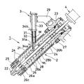
図中1は金属成形機で、筒体21の先端にノズル部材22を有する加熱保持筒2と、短柱形の成形材料Mの溶解供給装置3と、加熱保持筒2の後部の射出駆動装置4とからなる。
In the figure,
成形材料Mは、溶湯を固液共存温度領域の温度に急冷して、微細に球状化された固相を含む半溶融合金を冷却して円柱体(丸棒ともいう)に鋳造したソリッドからなり、固液共存温度領域においてチクソトロピー性状を呈するセミソリッドとなる低融点金属合金の金属素材からなる。 The molding material M consists of a solid that is rapidly cooled to a temperature in the solid-liquid coexistence temperature range, a semi-molten alloy containing a finely spheroidized solid phase is cooled, and cast into a cylindrical body (also called a round bar). It is made of a metal material of a low melting point metal alloy that becomes a semisolid exhibiting thixotropic properties in the solid-liquid coexistence temperature region.
上記加熱保持筒2は、筒体21の中程上側に設けた供給口に上記溶解供給装置3を備え、筒体外周囲にバンドヒータによる加熱手段24を備える。この加熱手段24は、成形材料Mとして用いられる低融点金属合金(たとえばマグネシウム合金、アルミニウム合金)の液相線温度と固相線温度との間の固液共存温度領域の温度に設定してある。
The heating and holding
加熱保持筒2は筒体後端部を支持部材23に取付けて、射出駆動装置4と共に水平面に対し45°の角度に斜設してある。この斜設により下向きに位置する上記ノズル部材22のノズル口と連通する先端部内は計量室25となっている。この計量室25には、上記射出駆動装置4により進退移動する射出手段26の射出プランジャ26aが進退自在に嵌挿してある。この射出プランジャ26aは外周面にシールリングを埋設した逆止弁26cを軸部周囲に進退自在に備えており、その逆止弁26cと軸部との間は、図では省略するがセミソリッド材料M1 の流路となっている。この流路の開閉は逆止弁26cの後端面と射出プランジャ後部のシートリングとの接離により行われる。
The heating and holding
上記射出手段26のロッド26bは、上記筒体21の上部内の閉塞部材27に貫挿して筒体内に設けた攪拌手段28の中空の回転シャフト28bに進退自在に挿通してあり、また回転シャフト28bの先端部周囲には複数の攪拌翼28aが取付けてある。
The
上記溶解供給装置3は、細長い管体の一端部内を閉塞して底部となし、その底部に溶融金属が流通する小径の供給流路31aを穿設した溶解筒31と、その外周囲に複数ゾーンに分割して個々に温度制御可能に設けたバンドヒータや誘導加熱器等による加熱手段32と、溶解筒31の上部に縦長に連結した供給筒33とからなり、加熱手段32は成形材料Mとして用いられる低融点金属合金が液相線温度以下の温度に設定してある。
なお、成形材料がチツプ等の粒状物の場合には、供給筒33の上端にホッパーが設けられる。
The melting and supplying
If the molding material is a granular material such as a chip, a hopper is provided at the upper end of the
また溶解供給装置3は、溶解筒31の底部側を筒体21に設けた材料供給口に差込み、供給筒33を上記支持部材23に固設したアーム部材29に取付けて加熱保持筒2に縦に設けられ、その下部から加熱保持筒2の溶湯面の内部までと、溶解筒31の上部の空間内とにアルゴンガス等の不活性ガスの注入管34a,34bが設けてある。
Further, the
上記溶解供給装置3において、多数ショット分の成形材料Mを供給筒33の上部開口から溶解筒31の底面まで落とし込むと、成形材料Mは溶解筒31の周囲からの加熱により溶解する。しかし、球状化された固相を含む成形材料Mでは、完全に溶融する前の固液共存状態で徐々に供給流路31aから筒体21内に流出して、液相線温度に加熱した加熱保持筒2に上記セミソリッド材料M1 として蓄積される。蓄積されたセミソリッド材料M1 の温度は計量後に射出されるまで固液共存温度領域の温度に保持される。成形材料Mがマグネシウム合金(AZ91D)の場合、加熱手段32の温度は、560°〜590℃に設定され、また加熱保持筒2の加熱手段24は560°〜610℃に設定される。
When the molding material M for a number of shots is dropped from the upper opening of the
加熱保持筒2に蓄積したセミソリッド材料M1 は、その一部が上記射出プランジャ26aの強制後退により流路から計量室25に流入して、該計量室25に1ショット分として蓄えられる。計量後にセミソリッド材料M1 は射出プランジャ26aの強制前進により、ノズル22から図示しない金型に直接又はホットランナーを通って射出され、所望形態の製品となる。
A part of the semi-solid material M 1 accumulated in the heating and holding
上記セミソリッド材料M1 の固相率は温度によって異なるが、球状の固相は固液共存温度の高低差に関係なく時間の経過と共に成長して大きくなり、それに伴い固相率も高くなって液相における固相の密度も増すようになる。上記マグネシウム合金では、570℃で30分保持した固相率は69%となり、固相は総体的に大きく成長するが200μを超えるものは少なく、チクソトロピー性状は保持されている。保持時間が30分を超過してゆくと200μを超える固相の割合が多くなり、固相率も75%以上にも及ぶようになって流動性が低下してゆく。 The solid phase ratio of the semi-solid material M 1 varies depending on the temperature, but the spherical solid phase grows and grows with time regardless of the difference in the solid-liquid coexistence temperature, and the solid ratio increases accordingly. The density of the solid phase in the liquid phase also increases. In the magnesium alloy, the solid phase ratio held at 570 ° C. for 30 minutes is 69%, and the solid phase grows large overall, but there are few cases exceeding 200 μm, and the thixotropic properties are maintained. When the retention time exceeds 30 minutes, the proportion of the solid phase exceeding 200 μ increases, the solid phase ratio reaches 75% or more, and the fluidity decreases.
加熱保持筒2に蓄積したセミソリッド材料M1 でも同様で、蓄積時間が30分以内であれば、射出プランジャ26aの強制後退による計量及び前進による金型への射出を支障なく円滑に行えるが、30分を経過すると流動性が低下し、また大きく成長した固相が流路に詰まるなどして、射出プランジャ26aの後退移動によるセミソリッド材料M1 の計量室25への送り込みがわるくなる。このため成形ごとの計量が不安定となって、金型への射出量の不足からショートショットとなり易い。
The same applies to the semi-solid material M 1 accumulated in the heating and holding
このようなセミソリッド材料M1 を、成形作業の終了時に排出して除去しないで置くと、加熱保持筒内にソリッド(図は省略)となって残存する。このソリッドは徐冷により大きく成長した結晶になるので組織は固く、固液共存温度領域の温度に再加熱して使用することはできないので、そのソリッドを成形開始時に除去して、新たなセミソリッド材料の供給による成形が行えるようにする必要がある。 Such semisolid material M 1, putting not removed discharged at the end of the molding operation, the solid (figure omitted) remains becomes into the heating holding cylinder. Since this solid becomes a crystal grown large by slow cooling, the structure is hard and cannot be used by reheating to a temperature in the solid-liquid coexistence temperature range, so the solid is removed at the start of molding and a new semi-solid It is necessary to be able to perform molding by supplying materials.
図2は、成形作業開始から本成形開始に至る行程を示すものである。
先ず前回の成形材料が残存した加熱保持筒2の温度を、液相線温度以上の温度に昇温する。残存材料がマグネシウム合金(AZ91D)では620°〜650℃に昇温し、残存材料を完全に溶融する。この溶融の過程で攪拌が必要かどうかを確認し、必要な場合には上記攪拌手段27を回転駆動して攪拌し、溶融の促進と溶融材料中の酸化物の分散を行う。残存材料の全量が完全溶融したら、加熱保持筒2の温度を固液共存温度領域の温度(560°〜610℃)まで降温する。
FIG. 2 shows a process from the start of the molding operation to the start of the main molding.
First, the temperature of the heating and holding
降温開始後に上記成形材料の供給と仮成形を開始する。供給は上記溶解筒31により成形材料Mをセミソリッド材料M1 に溶融して行う。仮成形は加熱保持筒2の温度が上記固液共存温度領域の温度に達するまで、上記射出手段26の後退による計量と、前進による図示しない金型への射出とを繰返して行う。降温時間は長いので、その時間内に溶融した残存材料の全てが、仮成形により加熱保持筒内から除かれて、継続供給されているセミソリッド材料M1 に置換される。置換後に加熱保持筒2の温度が上記固液共存温度領域の温度に達したら本成形を開始する。
The supply of the molding material and the temporary molding are started after the temperature drop is started. Supply is performed by melting the molding material M into the semi-solid material M 1 by the
1 金属成形機
2 加熱保持筒
3 溶解供給装置
4 射出駆動装置
21 筒体
22 ノズル部材
24 加熱手段
25 計量室
26 射出手段
26a 射出プランジャ
26b 射出ロッド
28 攪拌手段
28a 攪拌翼
31 溶解筒
32 加熱手段
DESCRIPTION OF
Claims (2)
成形作業開始時に、加熱保持筒の温度を成形材料の液相線温度以上の温度に昇温して、該加熱保持筒内にソリッドとなって残っている前回成形の残存材料を完全溶融したのち、加熱保持筒の温度を固液共存温度領域の温度まで降温しながら、セミソリッド材料に溶融した上記成形材料を供給して仮成形を行い、その仮成形を加熱保持筒の温度が固液共存温度領域に達するまで繰返し行ったのち本成形を開始することを特徴とする低融点金属合金の成形方法。 A metal material that exhibits thixotropic properties in the solid-liquid coexistence temperature region is used as a molding material, and the molding material is heated to a temperature in the solid-liquid coexistence temperature region by a melting supply device to form a semi-solid material in a solid-liquid coexistence state. the required amount is supplied accumulated in the heating holding cylinder of solid material, in the molding method of the low melting point metal alloy which emits one shot to the mold from the heating holding cylinder by the injection plunger,
At the start of the molding operation, the temperature of the heating and holding cylinder is raised to a temperature equal to or higher than the liquidus temperature of the molding material, and the remaining material of the previous molding remaining in the heating and holding cylinder as a solid is completely melted. While the temperature of the heating and holding cylinder is lowered to a temperature in the solid-liquid coexistence temperature range, the above molding material melted into the semisolid material is supplied to perform temporary molding, and the temperature of the heating and holding cylinder is solid-liquid coexistent. A method for forming a low-melting-point metal alloy, which is performed repeatedly after reaching a temperature range and then starts forming.
Priority Applications (4)
| Application Number | Priority Date | Filing Date | Title |
|---|---|---|---|
| JP2004055055A JP4289613B2 (en) | 2004-02-27 | 2004-02-27 | Low melting point metal alloy forming method |
| TW094103789A TWI314886B (en) | 2004-02-27 | 2005-02-04 | Method of molding low melting point metal alloy |
| US11/066,598 US7036551B2 (en) | 2004-02-27 | 2005-02-25 | Method of molding low melting point metal alloy |
| CNB2005100521688A CN100360261C (en) | 2004-02-27 | 2005-02-25 | Method of moulding low fuse alloyed metal |
Applications Claiming Priority (1)
| Application Number | Priority Date | Filing Date | Title |
|---|---|---|---|
| JP2004055055A JP4289613B2 (en) | 2004-02-27 | 2004-02-27 | Low melting point metal alloy forming method |
Publications (3)
| Publication Number | Publication Date |
|---|---|
| JP2005238312A JP2005238312A (en) | 2005-09-08 |
| JP2005238312A5 JP2005238312A5 (en) | 2005-10-27 |
| JP4289613B2 true JP4289613B2 (en) | 2009-07-01 |
Family
ID=34908820
Family Applications (1)
| Application Number | Title | Priority Date | Filing Date |
|---|---|---|---|
| JP2004055055A Expired - Fee Related JP4289613B2 (en) | 2004-02-27 | 2004-02-27 | Low melting point metal alloy forming method |
Country Status (4)
| Country | Link |
|---|---|
| US (1) | US7036551B2 (en) |
| JP (1) | JP4289613B2 (en) |
| CN (1) | CN100360261C (en) |
| TW (1) | TWI314886B (en) |
Families Citing this family (4)
| Publication number | Priority date | Publication date | Assignee | Title |
|---|---|---|---|---|
| JP4051350B2 (en) * | 2004-03-05 | 2008-02-20 | 日精樹脂工業株式会社 | Low melting point metal alloy forming method |
| CN100434208C (en) * | 2006-11-02 | 2008-11-19 | 上海交通大学 | Undercurrent type passage mechanism for magnesium alloy melt converter |
| JP4051393B2 (en) * | 2007-06-13 | 2008-02-20 | 日精樹脂工業株式会社 | Low melting point metal alloy forming method |
| US9017602B2 (en) * | 2010-02-05 | 2015-04-28 | Thixomat, Inc. | Method and apparatus of forming a wrought material having a refined grain structure |
Family Cites Families (11)
| Publication number | Priority date | Publication date | Assignee | Title |
|---|---|---|---|---|
| JPS6280487A (en) * | 1985-10-01 | 1987-04-13 | 東京瓦斯株式会社 | Method and device for dissolving nonferrous metal |
| GB2219236B (en) * | 1988-05-19 | 1992-01-15 | Tse Kwai Sum | Injection nozzle for an injection moulding machine |
| CN1072882A (en) * | 1989-10-12 | 1993-06-09 | 世纪工业株式会社 | Improved pressure-holding chamber type injection molding process and equipment |
| AU5178190A (en) * | 1989-10-12 | 1991-05-16 | Seiki Corporation Co., Ltd. | Improved pressure-holding chamber type injection molding process and apparatus |
| JP3415987B2 (en) * | 1996-04-04 | 2003-06-09 | マツダ株式会社 | Molding method of heat-resistant magnesium alloy molded member |
| US6135196A (en) * | 1998-03-31 | 2000-10-24 | Takata Corporation | Method and apparatus for manufacturing metallic parts by injection molding from the semi-solid state |
| JP3477126B2 (en) * | 1999-11-18 | 2003-12-10 | 株式会社日本製鋼所 | Discharge method of metal raw material in hot runner unit |
| JP4195767B2 (en) * | 2000-03-08 | 2008-12-10 | 徹一 茂木 | Casting method, casting equipment, metal material manufacturing method and metal material manufacturing apparatus |
| JP3624885B2 (en) * | 2001-12-28 | 2005-03-02 | 日精樹脂工業株式会社 | Metal forming machine |
| CA2453397A1 (en) * | 2003-01-27 | 2004-07-27 | Wayne Liu (Weijie) W. J. | Method and apparatus for thixotropic molding of semisolid alloys |
| JP4062688B2 (en) * | 2003-01-31 | 2008-03-19 | 日精樹脂工業株式会社 | Metal material melting and feeding device in metal forming machine |
-
2004
- 2004-02-27 JP JP2004055055A patent/JP4289613B2/en not_active Expired - Fee Related
-
2005
- 2005-02-04 TW TW094103789A patent/TWI314886B/en not_active IP Right Cessation
- 2005-02-25 CN CNB2005100521688A patent/CN100360261C/en not_active Expired - Fee Related
- 2005-02-25 US US11/066,598 patent/US7036551B2/en not_active Expired - Fee Related
Also Published As
| Publication number | Publication date |
|---|---|
| CN1660522A (en) | 2005-08-31 |
| US7036551B2 (en) | 2006-05-02 |
| CN100360261C (en) | 2008-01-09 |
| JP2005238312A (en) | 2005-09-08 |
| US20050194116A1 (en) | 2005-09-08 |
| TW200528258A (en) | 2005-09-01 |
| TWI314886B (en) | 2009-09-21 |
Similar Documents
| Publication | Publication Date | Title |
|---|---|---|
| US6840302B1 (en) | Method and apparatus for injection molding light metal alloy | |
| EP0765198B2 (en) | Method and apparatus for injection molding of semi-solid metals | |
| PL165468B1 (en) | Method of injecting molten metals and apparatus therefor | |
| JP2005219121A (en) | Machine for manufacturing metal material in solid-liquid coexisting state | |
| JP4289613B2 (en) | Low melting point metal alloy forming method | |
| US20010020526A1 (en) | Metal casting method and apparatus, and metal material manufacturing method and apparatus | |
| JP3783203B2 (en) | Low melting point metal material injection equipment | |
| US7032640B2 (en) | Method of molding low melting point metal alloy | |
| KR20090079179A (en) | Device for melting, storing, and feeding metal material from bar-shaped metal material intended for injection apparatus for molding metal product | |
| JP4051350B2 (en) | Low melting point metal alloy forming method | |
| US7165599B2 (en) | Melting and feeding method and apparatus of metallic material in metal molding machine | |
| JP4051393B2 (en) | Low melting point metal alloy forming method | |
| JP2005211958A (en) | Method for forming low melting point metal alloy | |
| JP2007105746A (en) | Injection molding apparatus | |
| JP4204878B2 (en) | Light alloy injection molding method and injection molding apparatus | |
| JP2014237172A (en) | Manufacturing apparatus of solid-liquid coexistent state metal, manufacturing method of solid-liquid coexistent state metal, and molding method using solid-liquid coexistent state metal | |
| JP3848939B2 (en) | Low melting point metal material injection equipment | |
| JP2000326062A (en) | Method and device for injection molding of light alloy and nozzle used for the same | |
| JP3954914B2 (en) | Light alloy injection molding method and injection molding apparatus | |
| JP3848936B2 (en) | Semi-melt forming method and molding machine for low melting point metal alloy | |
| JP2007061882A (en) | Injection molding machine, and screw for injection molding machine | |
| JP3593098B2 (en) | Metal forming machine | |
| JP4273045B2 (en) | Method of melting metal material in metal forming machine | |
| JP2005066692A (en) | Method and apparatus for producing rapidly cooled and solidified metallic thin material | |
| JP2008023539A (en) | Apparatus and method for injection-molding metal |
Legal Events
| Date | Code | Title | Description |
|---|---|---|---|
| A521 | Written amendment |
Free format text: JAPANESE INTERMEDIATE CODE: A523 Effective date: 20050722 |
|
| A621 | Written request for application examination |
Free format text: JAPANESE INTERMEDIATE CODE: A621 Effective date: 20050722 |
|
| A977 | Report on retrieval |
Free format text: JAPANESE INTERMEDIATE CODE: A971007 Effective date: 20060516 |
|
| A131 | Notification of reasons for refusal |
Free format text: JAPANESE INTERMEDIATE CODE: A131 Effective date: 20060523 |
|
| A521 | Written amendment |
Free format text: JAPANESE INTERMEDIATE CODE: A523 Effective date: 20060721 Free format text: JAPANESE INTERMEDIATE CODE: A821 Effective date: 20060721 |
|
| A02 | Decision of refusal |
Free format text: JAPANESE INTERMEDIATE CODE: A02 Effective date: 20070116 |
|
| A521 | Written amendment |
Free format text: JAPANESE INTERMEDIATE CODE: A821 Effective date: 20070215 |
|
| A521 | Written amendment |
Free format text: JAPANESE INTERMEDIATE CODE: A821 Effective date: 20070316 Free format text: JAPANESE INTERMEDIATE CODE: A523 Effective date: 20070316 |
|
| A911 | Transfer to examiner for re-examination before appeal (zenchi) |
Free format text: JAPANESE INTERMEDIATE CODE: A911 Effective date: 20070404 |
|
| A912 | Re-examination (zenchi) completed and case transferred to appeal board |
Free format text: JAPANESE INTERMEDIATE CODE: A912 Effective date: 20070518 |
|
| A521 | Written amendment |
Free format text: JAPANESE INTERMEDIATE CODE: A821 Effective date: 20090107 |
|
| A01 | Written decision to grant a patent or to grant a registration (utility model) |
Free format text: JAPANESE INTERMEDIATE CODE: A01 |
|
| R150 | Certificate of patent or registration of utility model |
Free format text: JAPANESE INTERMEDIATE CODE: R150 |
|
| FPAY | Renewal fee payment (event date is renewal date of database) |
Free format text: PAYMENT UNTIL: 20120410 Year of fee payment: 3 |
|
| FPAY | Renewal fee payment (event date is renewal date of database) |
Free format text: PAYMENT UNTIL: 20150410 Year of fee payment: 6 |
|
| LAPS | Cancellation because of no payment of annual fees |