JP4286247B2 - Broadcast receiver - Google Patents
Broadcast receiver Download PDFInfo
- Publication number
- JP4286247B2 JP4286247B2 JP2005285663A JP2005285663A JP4286247B2 JP 4286247 B2 JP4286247 B2 JP 4286247B2 JP 2005285663 A JP2005285663 A JP 2005285663A JP 2005285663 A JP2005285663 A JP 2005285663A JP 4286247 B2 JP4286247 B2 JP 4286247B2
- Authority
- JP
- Japan
- Prior art keywords
- state
- housing
- casing
- extended state
- antenna element
- Prior art date
- Legal status (The legal status is an assumption and is not a legal conclusion. Google has not performed a legal analysis and makes no representation as to the accuracy of the status listed.)
- Expired - Fee Related
Links
- 230000006870 function Effects 0.000 description 42
- 230000003287 optical effect Effects 0.000 description 30
- 238000001514 detection method Methods 0.000 description 17
- 230000005540 biological transmission Effects 0.000 description 9
- 238000010586 diagram Methods 0.000 description 9
- 238000003384 imaging method Methods 0.000 description 6
- 230000002452 interceptive effect Effects 0.000 description 6
- 230000007246 mechanism Effects 0.000 description 5
- 238000004891 communication Methods 0.000 description 3
- 230000001413 cellular effect Effects 0.000 description 2
- 230000008859 change Effects 0.000 description 2
- 238000006073 displacement reaction Methods 0.000 description 2
- 230000002265 prevention Effects 0.000 description 2
- 230000035945 sensitivity Effects 0.000 description 2
- 230000003213 activating effect Effects 0.000 description 1
- 230000004913 activation Effects 0.000 description 1
- 230000015572 biosynthetic process Effects 0.000 description 1
- 238000001914 filtration Methods 0.000 description 1
- 239000004973 liquid crystal related substance Substances 0.000 description 1
- 238000000034 method Methods 0.000 description 1
- 238000012986 modification Methods 0.000 description 1
- 230000004048 modification Effects 0.000 description 1
- 230000008569 process Effects 0.000 description 1
- 230000002250 progressing effect Effects 0.000 description 1
Images


Classifications
-
- H—ELECTRICITY
- H04—ELECTRIC COMMUNICATION TECHNIQUE
- H04M—TELEPHONIC COMMUNICATION
- H04M1/00—Substation equipment, e.g. for use by subscribers
- H04M1/02—Constructional features of telephone sets
- H04M1/0202—Portable telephone sets, e.g. cordless phones, mobile phones or bar type handsets
- H04M1/0206—Portable telephones comprising a plurality of mechanically joined movable body parts, e.g. hinged housings
- H04M1/0208—Portable telephones comprising a plurality of mechanically joined movable body parts, e.g. hinged housings characterized by the relative motions of the body parts
- H04M1/0235—Slidable or telescopic telephones, i.e. with a relative translation movement of the body parts; Telephones using a combination of translation and other relative motions of the body parts
- H04M1/0237—Sliding mechanism with one degree of freedom
-
- H—ELECTRICITY
- H01—ELECTRIC ELEMENTS
- H01Q—ANTENNAS, i.e. RADIO AERIALS
- H01Q1/00—Details of, or arrangements associated with, antennas
- H01Q1/12—Supports; Mounting means
- H01Q1/1235—Collapsible supports; Means for erecting a rigid antenna
-
- H—ELECTRICITY
- H01—ELECTRIC ELEMENTS
- H01Q—ANTENNAS, i.e. RADIO AERIALS
- H01Q1/00—Details of, or arrangements associated with, antennas
- H01Q1/12—Supports; Mounting means
- H01Q1/22—Supports; Mounting means by structural association with other equipment or articles
- H01Q1/24—Supports; Mounting means by structural association with other equipment or articles with receiving set
- H01Q1/241—Supports; Mounting means by structural association with other equipment or articles with receiving set used in mobile communications, e.g. GSM
- H01Q1/242—Supports; Mounting means by structural association with other equipment or articles with receiving set used in mobile communications, e.g. GSM specially adapted for hand-held use
- H01Q1/243—Supports; Mounting means by structural association with other equipment or articles with receiving set used in mobile communications, e.g. GSM specially adapted for hand-held use with built-in antennas
-
- H—ELECTRICITY
- H01—ELECTRIC ELEMENTS
- H01Q—ANTENNAS, i.e. RADIO AERIALS
- H01Q1/00—Details of, or arrangements associated with, antennas
- H01Q1/36—Structural form of radiating elements, e.g. cone, spiral, umbrella; Particular materials used therewith
- H01Q1/38—Structural form of radiating elements, e.g. cone, spiral, umbrella; Particular materials used therewith formed by a conductive layer on an insulating support
-
- H—ELECTRICITY
- H01—ELECTRIC ELEMENTS
- H01Q—ANTENNAS, i.e. RADIO AERIALS
- H01Q21/00—Antenna arrays or systems
- H01Q21/28—Combinations of substantially independent non-interacting antenna units or systems
-
- H—ELECTRICITY
- H01—ELECTRIC ELEMENTS
- H01Q—ANTENNAS, i.e. RADIO AERIALS
- H01Q9/00—Electrically-short antennas having dimensions not more than twice the operating wavelength and consisting of conductive active radiating elements
- H01Q9/04—Resonant antennas
- H01Q9/06—Details
- H01Q9/14—Length of element or elements adjustable
-
- H—ELECTRICITY
- H04—ELECTRIC COMMUNICATION TECHNIQUE
- H04M—TELEPHONIC COMMUNICATION
- H04M2250/00—Details of telephonic subscriber devices
- H04M2250/18—Details of telephonic subscriber devices including more than one keyboard unit
Description
本発明は、たとえば携帯電話機に代表される放送受信装置に関し、特に、2つの筐体が可動機構を有する放送受信装置に関する。 The present invention relates to a broadcast receiving apparatus represented by, for example, a mobile phone, and more particularly to a broadcast receiving apparatus in which two housings have a movable mechanism.
近年、携帯端末としての携帯電話機は、包含する機能が飛躍的に向上し、単なる通話専用の携帯型電話としての位置付けから、PDA(Personal Digital Assistants) に代表される携帯型情報端末としての位置付けへ変化している。
携帯電話機の高機能化の例として、撮像素子を搭載したカメラ機能があり、たとえば、100万画素を超える高画質な写真撮影、動画の記録やテレビ電話機能等を可能とするものもある。また、アナログテレビ用のチューナーを内蔵したテレビ付携帯電話機も市場に存在し、近い将来には、デジタル放送対応の携帯電話機が商品化されることが予想される。
2. Description of the Related Art In recent years, mobile phones as mobile terminals have drastically improved functions, and have moved from being positioned as simple mobile phones dedicated to calls to being positioned as portable information terminals represented by PDA (Personal Digital Assistants). It has changed.
As an example of enhancement of the functionality of a mobile phone, there is a camera function equipped with an image sensor, and there is, for example, a function that enables high-quality photography, video recording, videophone function, etc. exceeding 1 million pixels. In addition, TV-equipped mobile phones with built-in tuners for analog TVs are also present in the market, and mobile phones compatible with digital broadcasting are expected to be commercialized in the near future.
TVチューナーを内蔵している携帯電話機は、下記特許文献1に開示されている。
また、携帯時の利便性の観点から携帯電話機の小型化が急速に進む一方で、機能の向上に応じた表示画面の大型化に対する要求と両立させるため、近年の携帯電話機は、主に表示画面と受話器を有する第一筐体と、主に操作キーと送話器を有する第二筐体の2つのそれぞれ異なる筐体を、摺動自在に結合した構造とすることが主流となっている。
特に、筐体を閉じた状態で、大型のLCD(液晶画面)が常に視認可能に露出させることで、筐体を開いた状態にしなくても情報の閲覧や着信を行うことを可能としたスライド型の摺動機構を有する携帯電話機が注目されている。
In addition, while downsizing of mobile phones is rapidly progressing from the viewpoint of convenience when being carried, recent mobile phones mainly use display screens in order to satisfy the demand for enlargement of display screens in accordance with improved functions. And a first housing having a receiver and a second housing mainly having operation keys and a transmitter are mainly slidably coupled to each other.
Especially, the large LCD (liquid crystal screen) is exposed so that it can be seen with the case closed, allowing you to browse and receive information without having to open the case. Mobile phones having a sliding mechanism of a mold have been attracting attention.
ところで、近年の携帯電話機は、上述したように高機能化されている一方で、その高機能化に対して、ユーザの操作性が必ずしも十分ではないという課題がある。
すなわち、携帯電話機は、もとより、カメラ機能やデジタル放送受信機能などの付加機能にとって最適な形態を有していないので、通話機能からこれらの付加機能に移行する際に、操作キー等の操作性が煩雑となる場合がある。
By the way, while recent cellular phones have been enhanced in functionality as described above, there is a problem that user operability is not always sufficient for the enhancement in functionality.
That is, since the mobile phone does not have an optimum form for additional functions such as a camera function and a digital broadcast receiving function, the operability of operation keys and the like is not required when shifting from the call function to these additional functions. It can be cumbersome.
たとえば、携帯電話機は、携帯性の観点から全体の大きさに制約があるため、使用頻度の低い付加機能に対して、専用の操作キーを設けることができない。したがって、本来通話機能用に使用する他の操作キーを、付加機能を実行したときにだけ割り当てることが行われ、または、メニュー画面から何階層も辿って付加機能を呼び出す必要があり、操作性が煩雑となる。 For example, since the overall size of a mobile phone is limited from the viewpoint of portability, a dedicated operation key cannot be provided for an additional function that is not frequently used. Therefore, it is necessary to assign other operation keys that are originally used for the call function only when the additional function is executed, or it is necessary to trace the additional function by tracing through the menu screen, and the operability is improved. It becomes complicated.
また、デジタル放送の受信では、当該デジタル放送を通じて、クイズ番組やゲームへの参加、テレビショッピング等の双方向サービスが行われ、これらのサービスを利用するために視聴者側からの入力操作が必要になるが、携帯電話機で双方向サービスを利用するためにはカラーボタン等の操作キーを新たに設ける必要がある。
従来の携帯電話機の操作キーにカラーボタン機能を付加することも可能ではあるが、操作性が煩雑になり非常に使いにくい。また、全く新規にカラーボタン等を設ける場合にも、配置する位置が操作性に大きく影響するうえ、携帯性の観点から、これらのカラーボタンを含む操作キーを配設する携帯電話機全体の筐体の大きさが制約される。
したがって、付加機能に対する操作キーを、その操作性が煩雑とならないように携帯端末の筐体に配列する点が非常に重要な課題となっている。
Also, when receiving digital broadcasts, interactive services such as participation in quiz programs and games and TV shopping are performed through the digital broadcasts, and input operations from the viewer side are necessary to use these services. However, in order to use the interactive service on the mobile phone, it is necessary to newly provide operation keys such as color buttons.
Although it is possible to add a color button function to the operation keys of a conventional mobile phone, the operability becomes complicated and it is very difficult to use. In addition, even when a color button or the like is newly provided, the position of the mobile phone greatly affects the operability, and from the viewpoint of portability, the entire mobile phone casing in which operation keys including these color buttons are provided. Is limited in size.
Therefore, it is a very important issue to arrange the operation keys for the additional functions in the casing of the portable terminal so that the operability is not complicated.
本発明はかかる事情に鑑みてなされたものであり、その目的は、小型で携帯性に優れ、かつ、通話機能以外の様々な機能に対する操作性が高い放送受信装置を提供することにある。 The present invention has been made in view of such circumstances, and an object of the present invention is to provide a broadcast receiving apparatus that is small in size, excellent in portability, and high in operability for various functions other than a call function.
上記目的を達成するために、本発明は、第1のアンテナ素子を設けるとともに、表示画面を露出して配設する第1の筐体と、第2のアンテナ素子を設けるとともに、少なくとも複数の操作キーを含む第2の筐体と、前記第1の筐体に対して前記第2の筐体を摺動させることにより、全体の形態が縮退する縮退状態と、前記縮退状態から展伸する第1の展伸状態と、を形成可能とする摺動手段と、前記第1の展伸状態から更に同じ方向に展伸させた第2の展伸状態と、を含み、
前記第1の展伸状態において、前記第1の筐体の前記第1のアンテナ素子と前記第2の筐体の前記第2のアンテナ素子が接続し、前記第2の展伸状態において、前記第1の展伸状態における接続位置と異なる位置で前記第1の筐体の前記第1のアンテナ素子と前記第2の筐体の前記第2のアンテナ素子が接続することで、前記第1の展伸状態と前記第2の展伸状態でアンテナのアンテナ長が異なるように構成されたことを特徴とする放送受信装置である。
In order to achieve the above object, the present invention is provided with a first antenna element, a first casing that exposes a display screen, a second antenna element, and at least a plurality of operations. A second housing including a key, and a sliding state in which the entire housing is retracted by sliding the second housing with respect to the first housing, and a first housing that is expanded from the retracted state . 1 extending state, and includes a sliding means that can be formed, and a second extending state that is further extended in the same direction from the first extending state,
In the first extended state, the first antenna element of the first casing and the second antenna element of the second casing are connected, and in the second extended state, the The first antenna element of the first casing and the second antenna element of the second casing are connected at a position different from the connection position in the first extended state, whereby the first The broadcast receiving apparatus is configured such that the antenna length of the antenna is different between the extended state and the second extended state.
好適には、前記展伸状態において、前記複数の操作キーのうち、それぞれ異なる操作キーを露出する。 Preferably, in the extended state, different operation keys among the plurality of operation keys are exposed.
好適には、前記展伸状態において露出する操作キーは、放送用アプリケーションのために使用する操作キーである。 Preferably, the operation key exposed in the expanded state is an operation key used for a broadcast application.
本発明の放送受信装置によれば、小型で携帯性に優れ、かつ、通話機能以外の様々な機能に対する操作性が高い。 According to the broadcast receiving apparatus of the present invention, it is small and excellent in portability, and has high operability for various functions other than the call function.
以下、本発明の放送受信装置として放送受信機能を有する携帯端末の一実施形態である携帯電話機について、添付図面に関連付けて述べる。
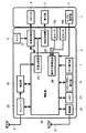
図1は、本実施形態の携帯電話機の一構成例を示す回路ブロック図である。
本実施形態の携帯電話機は、後述するように、第一筐体1および第二筐体2の2つの筐体が相互に摺動可能に連結されたスライド式の携帯電話機である。図1では、第一筐体1および第二筐体2の各筐体毎に割り当てられる回路ブロックの各要素を記載している。
以下、回路のブロックを構成する構成要素について説明する。
Hereinafter, a mobile phone as an embodiment of a mobile terminal having a broadcast receiving function as a broadcast receiving apparatus of the present invention will be described with reference to the accompanying drawings.
FIG. 1 is a circuit block diagram showing a configuration example of a mobile phone according to the present embodiment.
As will be described later, the mobile phone according to the present embodiment is a slide type mobile phone in which two housings of a
Hereinafter, components constituting the circuit block will be described.
無線部23は、送受信アンテナを含んで構成され、電波を利用した無線通信で行うために、制御部22で処理された音声情報、電子メール等を変調して送受信アンテナ31により図示しない基地局に送信する。
また、無線部23は、基地局から無線により送信され、送受信アンテナ31で受信した電子メールや音声情報等の各種情報を復調して制御部22に送出する。
The
The
メモリ24は、EEPROM等の不揮発性メモリを含んで構成され、通話やメールの送受信のための制御プログラム、デジタル放送、インターネットブラウザ、メッセージデータ、名前および電話番号が登録されたアドレス帳のほか、本実施形態の携帯電話機が有する様々なアプリケーションを実行するためのアプリケーションプログラム(機能)を記憶する。制御部22は、たとえば、アプリケーションを起動するために、メモリ24が記憶するアプリケーションプログラムをRAM領域にロードする。
The
キー操作部7は、第二筐体2に配設された複数の操作キーを含んで構成される。複数の操作キーとしては、終了(終話)/電源キー、開始(発呼)キー、数字等に対応した操作キーなどの通話機能に要する複数の操作キーが含まれる。これらの操作キーを介して、ユーザからの入力情報が制御部22に送出される。
カラーボタン操作部6は、デジタル放送の双方向サービスを利用するための操作ボタンを含んで構成される。かかる操作ボタンは、専らデジタル放送の利用のために使用される。
サブキー操作部5は、第一筐体1に配設された複数の操作キーを含んで構成される。たとえば、後述する縮退状態(筐体全体が最も小さくなる状態)において、ユーザが受信した電子メールのテキストを表示させる等の簡易な機能を使用するための操作キーが含まれる。
The
The color
The sub
送受信アンテナ9、チューナー25、復調部26、および制御部22内の多重分離部29は、デジタルテレビジョン放送(以下、デジタル放送)の受信機能を構成し、制御部22により、デジタル放送の受信/映像表示/音声出力が制御される。
すなわち、図示しない放送局より送受信アンテナ9が受信した信号は、チューナー25によりユーザ所望のチャンネル(周波数帯)が選択された後、復調部26によりOFDM復調されてトランポートストリームデータ(TSデータ)として抽出される。
多重分離部29は、抽出されたTSデータを、主として画像データと音声データに分離する。
なお、デジタル放送では、ゲームへの参加、テレビショッピング等の双方向サービスが行われるが、実施形態に係る携帯電話機から基地局へ信号を送信する際には、制御部22により信号が変調され、送受信アンテナ31を介して送出される。
The transmission /
That is, a signal received by the transmitting / receiving
The demultiplexing unit 29 mainly separates the extracted TS data into image data and audio data.
In digital broadcasting, interactive services such as participation in games and TV shopping are performed. When a signal is transmitted from the mobile phone according to the embodiment to the base station, the signal is modulated by the control unit 22, It is transmitted via the transmission /
画像処理部28は、分離された画像データに基づいて、表示部3を駆動して表示部3のLCDに画像を表示させる。なお、画像処理部28は、デジタル放送の画像だけではなく、通話機能に応じたいわゆる待受画面や電話番号などを表示部3に表示させることは言うまでもない。
Based on the separated image data, the image processing unit 28 drives the
音声処理部27は、マイクロフォン8より集音したユーザの音声に対して、フィルタリング処理や符号化処理などの所定の処理を行って音声データを生成する。生成された音声データは、たとえば、無線部23および送受信アンテナ31を介して図示しない基地局へ通話のために送出される。
また、音声処理部27は、送受信アンテナ31および無線部23を介して受信した音声データや、多重分離部29により分離された音声データを増幅して、スピーカ4に音声を出力させる。
The
The
光センサ10a,10bは、第二筐体2の表面に取り付けられたフォトダイオードなどの光検出素子を含んで構成される。たとえば、光が照射されると、フォトダイオードが導通状態となるので、フォトダイオードを流れる電流を検出することにより、照射される光量を検出する。
制御部22の一部を構成する筐体状態検出部30は、各光センサ10a,10bが検出した光量に基づいて、摺動機構により変更する筐体の状態(形態)を検出する。筐体状態検出部30の検出原理については、後述する。
なお、筐体状態検出部30は、本発明の検出手段の一実施形態である。
The
The housing state detection unit 30 that constitutes a part of the control unit 22 detects the state (form) of the housing that is changed by the sliding mechanism, based on the amount of light detected by each of the
The housing state detection unit 30 is an embodiment of the detection means of the present invention.
本発明の制御手段としての制御部22は、マイクロコンピュータを主体として構成され、実施形態に係る携帯電話機の全体の制御を行う。たとえば、制御部22は、無線部23における各種情報の無線による送受信の制御、音声処理部27に対する音声情報の処理、表示部3への情報の表示制御、キー操作部7およびサブキー操作部5からの入力情報に応じた処理、メモリ24に対するアクセス制御等を行う。
特に、本実施形態に係る制御部22は、筐体状態検出部30の検出結果に応じて、異なるアプリケーションプログラムを起動させる。アプリケーションプログラムとしては、たとえば、上述したデジタル放送のアプリケーションなどがある。
The control unit 22 as control means of the present invention is configured mainly with a microcomputer, and controls the entire mobile phone according to the embodiment. For example, the control unit 22 controls transmission / reception of various types of information in the
In particular, the control unit 22 according to the present embodiment activates different application programs according to the detection result of the housing state detection unit 30. The application program includes, for example, the above-described digital broadcast application.
次いで、実施形態に係る携帯電話機の形態について述べる。
図2は、実施形態に係る携帯電話機が第一筐体1および第二筐体2の連結状態に応じて取りうる形態の正面図と側面図であり、(a)は縮退状態を、(b)および(c)はそれぞれ異なる方向に展伸した展伸状態を、それぞれ示す。
(a)に示す縮退状態は、第一筐体1および第二筐体2の相対変位により、筐体全体が最も小さくなる状態である。縮退状態は、ユーザにとって携帯性が優れる。
また、縮退状態では、図に示すように、第一筐体1の上面に配設されたスピーカ4と表示部3とサブキー操作部5が露出され、第二筐体2の上面に配設されたマイクロフォン8が露出されている。
Next, the form of the mobile phone according to the embodiment will be described.
2A and 2B are a front view and a side view of a form that the mobile phone according to the embodiment can take in accordance with the connection state of the
The contracted state shown in (a) is a state in which the entire casing is minimized by the relative displacement of the
In the contracted state, as shown in the figure, the speaker 4, the
(b)に示す展伸状態(以下、この状態を第一展伸状態と称する)では、第二筐体2に対して第一筐体1がスライドして展伸されることにより、縮退状態と比較して、第二筐体2の上面に配設されたキー操作部7と光センサ10aが新たに露出される。
第一展伸状態は、終了(終話)/電源キー、開始(発呼)キー、数字等に対応した操作キーを含むキー操作部7が露出して使用可能となるので、主として、音声/電子メール等による通信機能を利用する場合に好適である。
なお、第一展伸状態は、本発明の第1の状態に対応する。
In the extended state shown in (b) (hereinafter, this state is referred to as the first extended state), the
In the first extended state, the
The first extended state corresponds to the first state of the present invention.
(c)に示す展伸状態(以下、この状態を第二展伸状態と称する)では、第二筐体2に対して第一筐体1がスライドして展伸されることにより、縮退状態と比較して、第二筐体2の上面に配設されたカラーボタン操作部6と光センサ10bが新たに露出されるとともに、第一展伸状態で露出されたキー操作部7は、第二展伸状態では露出されない。
第二展伸状態は、デジタル放送の双方向サービスを利用可能とするカラーボタン操作部6が露出して使用可能となる。
なお、第二展伸状態は、本発明の第2の状態に対応する。
In the extended state shown in (c) (hereinafter, this state is referred to as a second extended state), the
In the second extended state, the color
The second extended state corresponds to the second state of the present invention.
以上、実施形態に係る携帯電話機が取りうる形態について述べたが、次いで、かかる複数の形態(縮退状態/第一展伸状態/第二展伸状態)を実現するための構造について、図3乃至図5に関連付けて述べる。
図3は、第一筐体1および第二筐体2のスライド構造を説明するための図であり、(a)は携帯電話機を背面から見た図を、(b)は携帯電話機を前面から見た図を、それぞれ示す。なお、理解の容易のため、(a)では、第一筐体1を実線で表し、第二筐体2を点線で表しており、また、(b)では、第二筐体2を実線で表し、第一筐体1を点線で表している。
As described above, the modes that can be taken by the mobile phone according to the embodiment have been described. Next, the structure for realizing such a plurality of modes (degenerated state / first extended state / second extended state) is described with reference to FIGS. This will be described with reference to FIG.
3A and 3B are diagrams for explaining the sliding structure of the
図3(a)に示すように、第一筐体1の背面1aには、直線状の第一スライドレール11と、各筐体の相対変位を規制するためのレール溝13を含む第二スライドレール12とが設けられている。
一方、図3(b)に示すように、第二筐体2の前面2aには、第一スライドレール11と嵌合する固定ピン14と、第二スライドレール12と嵌合する可動ピン15とが配置されている。
すなわち、第二筐体2の前面2aに設けられた各ピンと、第一筐体1の背面1aに設けられた各スライドレールとが嵌合することにより、第一筐体1と第二筐体2がスライド可能に連結状態となる。
なお、第一筐体の背面1aおよび第二筐体の前面2aに設けられた上述の構造は、本発明の摺動手段の一実施形態を構成する。
As shown in FIG. 3A, the back surface 1a of the
On the other hand, as shown in FIG. 3 (b), a fixed
That is, each pin provided on the
In addition, the above-mentioned structure provided in the back surface 1a of the 1st housing | casing and the
図4は、第二筐体2の前面2aの構造の一例を説明するための図である。
図に示すように、第二筐体2の前面2aには固定ピン14が固定される。固定ピン14の横方向には、矩形の凹部16が設けられ、この凹部16の底面には摺動穴17が設けられる。
可動ピン15は、摺動穴17に沿って直立に変位するように、摺動穴17により支持される。また、可動ピン15は、図に示すように、弾性部材18を介して、凹部16の固定ピン14側の一端に取り付けられている。
したがって、可動ピン15は、凹部16内の摺動穴17に沿って図4において左右に摺動する構成となっている。
また、固定ピン14および可動ピン15の各ピンの上部には、第一筐体1から第二筐体2が脱落しないように、第一筐体1の各スライドレールの幅より大きい径の円形の脱落防止板19が取り付けられている。
FIG. 4 is a diagram for explaining an example of the structure of the
As shown in the figure, a fixing
The
Therefore, the
In addition, a circular shape having a diameter larger than the width of each slide rail of the
図5は、実施形態の携帯電話機のスライド機構の動作を説明するための図であり、(a)は縮退状態を、(b)は展伸途中の状態を、(c)は第一展伸状態を、(d)は第二展伸状態を、それぞれ示す。
(a)に示す縮退状態では、可動ピン15が第二スライドレール12の中央のレール溝13に嵌合した状態で固定している。この状態では、たとえば、ばねとしての弾性部材18は、自然長よりも伸びた状態であり、第二筐体2の中央方向に力が加わっているので、可動ピン15は第二スライドレール12の中央のレール溝13に固定される。これにより、筐体全体が最も小さくなるので携帯性が優れる。
また、縮退状態では、(a)に示すように、縮退状態では、光センサ10aおよび10bがともに露出しないように構成する。その結果、各センサの出力レベルに差が生じない。
5A and 5B are diagrams for explaining the operation of the slide mechanism of the mobile phone according to the embodiment, in which FIG. 5A shows a contracted state, FIG. 5B shows a state during expansion, and FIG. 5C shows a first extension. (D) shows the second extended state.
In the contracted state shown in (a), the
Further, in the degenerated state, as shown in (a), in the degenerated state, the
縮退状態から、第一筐体1を上方向に力を加えると、可動ピン15は、レール溝13からはずれ、(b)に示すように、第二スライドレール12に沿って移動可能な状態となる。
(b)に示すように、第一展伸状態および第二展伸状態のいずれの状態でもない場合には、縮退状態と同様、光センサ10aおよび10bがともに露出しないように構成する。その結果、各センサの出力レベルに差が生じない。
When a force is applied to the
As shown in (b), when neither the first extended state nor the second extended state is set, the
そして、(b)の状態から、第一筐体1をさらに上方向に移動させると、(c)に示すように、可動ピン15が第二スライドレール12の最下端のレール溝13に固定された第一展伸状態となる。これにより、終了(終話)/電源キー、開始(発呼)キー、数字等に対応した操作キーを含むキー操作部7が露出して使用可能となるので、主として、音声/電子メール等による通信機能を利用する場合に操作性が向上する。
この状態では、(c)に示すように、光センサ10aのみが露出し、光センサ10bが露出しないように構成する。その結果、光センサ10aのセンサ出力のみが高いレベルを示す。
When the
In this state, as shown in (c), only the
また、縮退状態から、第一展伸状態とは逆方向に第一筐体1を摺動させると、(d)に示すように、可動ピン15が第二スライドレール12の最上端のレール溝13に固定された第二展伸状態となる。これにより、カラーボタン操作部6が露出するので、デジタル放送の双方向サービスを利用可能とする場合に操作性が向上する。
この状態では、(d)に示すように、光センサ10bのみが露出し、光センサ10aが露出しないように構成する。その結果、光センサ10bのセンサ出力のみが高いレベルを示す。
Further, when the
In this state, as shown in (d), only the
筐体状態検出部30は、光センサ10a,10bの各センサ出力に基づいて、筐体の状態(縮退状態/第一展伸状態/第二展伸状態)を検出する。
図6は、光センサ10a,10bの各センサ出力に応じた制御部22での処理を示すフローチャートである。
図6において、先ず、制御部22内の筐体状態検出部30は、各光センサの出力を比較し、各光センサの出力が同一である場合には(ステップST10)、筐体が第一展伸状態または第二展伸状態のいずれの状態となっていないと判断する。すなわち、第一筐体1および第二筐体2の位置関係が、図5(a)および(b)に示すように状態である場合には、各光センサ10a,10bは露出されず、ともに出力レベルに差が生じないので、ステップST10の条件が成立する。
ステップST10の条件が成立する場合には、制御部22は何も実行しない。
The housing state detection unit 30 detects the state of the housing (degenerated state / first extended state / second extended state) based on the sensor outputs of the
FIG. 6 is a flowchart showing processing in the control unit 22 according to the sensor outputs of the
In FIG. 6, first, the housing state detection unit 30 in the control unit 22 compares the outputs of the optical sensors. If the outputs of the optical sensors are the same (step ST10), the housing is the first. It is determined that neither the extended state nor the second extended state is reached. That is, when the positional relationship between the
When the condition of step ST10 is satisfied, the control unit 22 does nothing.
また、光センサ10aのセンサ出力が光センサ10bのセンサ出力よりも大きい場合には(ステップST11)、制御部22は、所定のアプリケーションAを起動させる(ステップST12)。
すなわち、第一筐体1および第二筐体2の位置関係が、図5(c)に示す第一展伸状態である場合には、光センサ10aが露出され、光センサ10bは露出されず、光センサ10aのみが高い出力レベルとなって、ステップST11の条件が成立する。かかる場合には、筐体状態検出部30は、筐体が第一展伸状態であることを検出し、制御部22は、その検出結果に応じたアプリケーションを起動させる。なお、すでにアプリケーションBが起動している場合には、特に新たな処理は行わない。
When the sensor output of the
That is, when the positional relationship between the
第一展伸状態では、キー操作部7が露出するように筐体を構成したので、たとえば、アプリケーションAとして予め通話機能のプログラムを登録しておけば、ユーザは、筐体を第一展伸状態に展伸させると同時に、すぐに通話を行うことができる。
In the first extended state, the case is configured such that the
また、光センサ10aのセンサ出力が光センサ10bのセンサ出力よりも小さい場合には(ステップST11)、制御部22は、アプリケーションAと異なる所定のアプリケーションBを起動させる(ステップST13)。
すなわち、第一筐体1および第二筐体2の位置関係が、図5(d)に示す第二展伸状態である場合には、光センサ10aが露出されず、光センサ10bは露出され、光センサ10bのみが高い出力レベルとなって、ステップST11の条件が成立しない。かかる場合には、筐体状態検出部30は、筐体が第二展伸状態であることを検出し、制御部22は、その検出結果に応じたアプリケーションを起動させる。なお、すでにアプリケーションBが起動している場合には、特に新たな処理は行わない。
When the sensor output of the
That is, when the positional relationship between the
第二展伸状態では、カラーボタン操作部6が露出するように筐体を構成したので、たとえば、アプリケーションBとして予めデジタル放送の受信プログラムを登録しておけば、ユーザは、筐体を第二展伸状態に展伸させると同時に、すぐにデジタル放送を視聴することができる。
また、第二展伸状態では、キー操作部7が露出されないので、デジタル放送の視聴時に操作可能な操作キーが制限され、ユーザの操作性が向上する。すなわち、ユーザは、多くの操作キーから必要な操作キーを選択する煩わしさから解放される。
In the second extended state, the casing is configured so that the color
In the second extended state, since the
なお、筐体が縮退状態や第一展伸状態である場合においても、上記アプリケーションBとして例示したデジタル放送の受信プログラムを、起動メニュー等を選択して起動する構成とすることは可能であるが、制御部22を上述した構成とすることにより、ユーザは、縮退状態から第二展伸状態にスライドさせるだけでデジタル放送を受信することが可能となり、操作性が向上する。
また、制御部22は、筐体状態検出部30が縮退状態であることを検出した時点、または、ユーザによる特定の操作キーに対する操作がなされた時点で、アプリケーションBを終了させるように構成する。
Even when the housing is in the contracted state or the first extended state, the digital broadcast receiving program exemplified as the application B can be configured to start by selecting a start menu or the like. By configuring the control unit 22 as described above, the user can receive a digital broadcast simply by sliding the retracted state to the second expanded state, and the operability is improved.
Further, the control unit 22 is configured to terminate the application B when it is detected that the housing state detection unit 30 is in the degenerated state or when an operation is performed on a specific operation key by the user.
以上述べたように、本実施形態に係る携帯電話機によれば、2つの筐体を異なる方向に展伸可能に連結させ、かつ、各展伸状態に応じて必要な操作キーのみを露出するように構成したので、携帯電話機の操作性が格段に向上するとともに、不必要な操作キーが露出しないので、誤操作を防止することができる。
本実施形態に係る携帯電話機によれば、携帯電話機の各機能に応じて、最適な形態となるように、筐体の状態(縮退状態/第一展伸状態/第二展伸状態)を設定したので、携帯性と各機能の操作性を両立させることができる。
As described above, according to the mobile phone according to the present embodiment, the two casings are connected so as to be extendable in different directions, and only the necessary operation keys are exposed according to each extended state. Thus, the operability of the mobile phone is remarkably improved, and unnecessary operation keys are not exposed, so that an erroneous operation can be prevented.
According to the mobile phone according to the present embodiment, the state of the housing (degenerated state / first extended state / second extended state) is set so as to be in an optimum form according to each function of the mobile phone. Therefore, both portability and operability of each function can be achieved.
本実施形態に係る携帯電話機によれば、展伸状態に応じて、操作キーの露出領域が異なるので、操作キーを主として配列する筐体(本実施形態では、第二筐体2)に、必要な操作キーを有効にレイアウトさせることができる。
本実施形態に係る携帯電話機によれば、筐体の展伸方向が検出されることにより、筐体の状態(縮退状態/第一展伸状態/第二展伸状態)に応じたアプリケーションを起動させるので、ユーザは、アプリケーションを起動させるために煩雑な操作を行う必要がなく、また、起動時間が短縮される。
According to the mobile phone according to the present embodiment, since the exposure area of the operation key differs depending on the expanded state, it is necessary for the casing (
According to the mobile phone according to the present embodiment, when the expansion direction of the casing is detected, an application corresponding to the state of the casing (degenerated state / first extended state / second extended state) is started. Therefore, the user does not need to perform a complicated operation to activate the application, and the activation time is shortened.
本発明の実施形態は、上述した内容に拘泥せず、本発明の要旨を変更しない範囲で様々な改変が可能である。
たとえば、上述した実施形態に係る携帯電話機では、筐体状態検出部30は、2つの光センサの出力に基づいて、筐体状態を検出するが、光センサに限らず、他の様々なセンサを適用させることが可能である。たとえば、第一筐体1の3つのレール溝付近の位置に磁気センサを3つ配置し、第二筐体2の可動ピン15にマグネットを配置することにより、筐体状態を検出することも可能であるし、第一スライドレール11に沿って配設するポテンショ(可変抵抗器)により、筐体状態を検出してもよい。
The embodiments of the present invention are not limited to the above-described contents, and various modifications can be made without departing from the scope of the present invention.
For example, in the mobile phone according to the above-described embodiment, the casing state detection unit 30 detects the casing state based on the outputs of the two optical sensors. It is possible to apply. For example, it is also possible to detect the housing state by arranging three magnetic sensors near the three rail grooves of the
また、本実施形態に係る携帯電話機では、筐体の状態が縮退状態と第一展伸状態、第二展伸状態の3つの状態で説明したが、第二展伸状態から更に別の状態に摺動させることも可能である。
例えば、上述した実施形態の第二展伸状態でデジタル放送受信機能を起動する場合を説明したが、第二展伸状態から同じ方向に更に摺動させた第三展伸状態を設け、第二展伸状態と第三展伸状態でデジタル放送受信用アンテナのアンテナ長を変えることによって、放送の受信状態を改善することが可能である。
これは、操作性の向上を目的としてコンパクトな第二展伸状態による放送受信を可能としているが、時々刻々と変わる放送波の受信環境に対して、上記操作性の利点を維持しつつ放送受信の受信感度をユーザの容易な操作により向上させることを目的としている。
Further, in the mobile phone according to the present embodiment, the case has been described in the three states of the contracted state, the first stretched state, and the second stretched state, but the second stretched state is further changed to another state. It is also possible to make it slide.
For example, although the case where the digital broadcast receiving function is activated in the second extended state of the above-described embodiment has been described, a third extended state is provided by further sliding in the same direction from the second extended state. By changing the antenna length of the digital broadcast receiving antenna between the extended state and the third extended state, it is possible to improve the broadcast reception state.
This makes it possible to receive broadcasts in a compact second extended state for the purpose of improving operability. However, it is possible to receive broadcasts while maintaining the operability advantages described above for the broadcast wave reception environment that changes from moment to moment. It is an object of the present invention to improve the reception sensitivity of the user by an easy operation of the user.
図7は、第三展伸状態を設けた携帯電話機の外観と、各状態でのデジタル放送受信用アンテナの配置の様子を示した図であり、(a)は縮退状態を、(b)は第一展伸状態を、(c)は第二展伸状態を、(d)は第三展伸状態を、それぞれ示している。(c)の第二展伸状態になると放送用アプリケーションが起動するとともに、この放送用アプリケーションに用いる操作部が露出する。 FIG. 7 is a diagram showing the appearance of the mobile phone provided with the third extended state and the state of arrangement of the digital broadcast receiving antenna in each state, where (a) shows a degenerated state, (b) shows The first extended state, (c) shows the second extended state, and (d) shows the third extended state. In the second extended state of (c), the broadcast application is activated and the operation unit used for this broadcast application is exposed.
また、図8は、第一筐体および第2筐体に配置される第一のアンテナ素子および第2のアンテナ素子の形成例を示す図であり、(a)は第一筐体に配置された第一のアンテナ素子を、(b)は第二筐体に配置された第二のアンテナ素子を、(c)は第一筐体および第二筐体がスライド可能に配置され第一アンテナ素子と第二アンテナ素子との接続状態を、それぞれ示している。
また、図9は、各状態でのデジタル放送受信用アンテナの可変状態を示す図であり、(a)は縮退状態を、(b)は第二展伸状態を、(c)は第三展伸状態を、それぞれ示している。
FIG. 8 is a diagram showing an example of forming the first antenna element and the second antenna element arranged in the first casing and the second casing, and (a) is arranged in the first casing. (B) is the second antenna element disposed in the second housing, and (c) is the first antenna element in which the first housing and the second housing are slidably disposed. And the connection state of the second antenna element.
FIG. 9 is a diagram showing the variable state of the digital broadcast receiving antenna in each state, where (a) is a degenerated state, (b) is a second expanded state, and (c) is a third expanded state. Each stretched state is shown.
デジタル放送受信用アンテナは第一筐体1に配置される第一のアンテナ素子101と、第二筐体2に配置される第二のアンテナ素子201から構成され、第一筐体1と第二筺体2の摺動面側で接続されている。
図8および図9に示すように、第一筐体1に配置される第一のアンテナ素子101はたとえば長さLの直線状(棒状)に形成され、第二筐体2に配置される第二のアンテナ素子201はたとえば矩形波状に形成されている。
そして、第二のアンテナ素子201の一端部201aが第一のアンテナ素子101の側部に当接し、第一筐体1と第二筐体2との操作状態に応じて第二のアンテナ素子201の一端部201aが第一のアンテナ素子101の側部を摺動する。
これにより、第二展伸状態と第三展伸状態でデジタル放送受信用アンテナのアンテナ長を変えることによって、放送の受信状態を改善している。
The digital broadcast receiving antenna includes a
As shown in FIGS. 8 and 9, the
Then, the one
Thus, the broadcast reception state is improved by changing the antenna length of the digital broadcast receiving antenna between the second extended state and the third extended state.
携帯電話機が第二展伸状態となり、デジタル放送受信機能が起動された時点では、デジタル放送受信用アンテナは図7(c)に示すようにL1の長さとなっている。第二展伸状態から第一筺体1を更に摺動させると図7(d)に示すように、携帯電話機は第三展伸状態となり、デジタル放送受信用アンテナはL2の長さとなり、受信状態を変更することが可能である。
アンテナ素子を長さL2のほうが長さL1より受信感度が良いので、利便性もさらに向上し、第二展伸状態でデジタル放送受信機能を起動させて、電波の受信状況にあわせて第二展伸状態から第三展伸状態に簡単に遷移させてよりよい受信状態で放送を受信することが可能となる。
これにより、放送波の受信状態が良ければ第二展伸状態で使用し、放送波の受信状態が良くなければ必要に応じて第三展伸状態にすることにより、ユーザの状況に応じた使い方を簡単に行うことができる。
When the mobile phone is in the second extended state and the digital broadcast receiving function is activated, the digital broadcast receiving antenna has a length L1 as shown in FIG. 7C. When the
Since the antenna element with the length L2 has better reception sensitivity than the length L1, the convenience is further improved, the digital broadcast reception function is activated in the second extended state, and the second exhibition is performed according to the radio wave reception status. It is possible to easily change from the extended state to the third extended state and receive the broadcast in a better receiving state.
If the reception state of the broadcast wave is good, it is used in the second extension state. If the reception state of the broadcast wave is not good, the third extension state is used if necessary. Can be done easily.
また、上述した実施形態に係る携帯電話機では、第二展伸状態での使用態様がデジタル放送の視聴である場合について述べたが、デジタル放送に限らず、他の様々なアプリケーションに適用することができる。また、縮退状態でデジタル放送を視聴している場合に、展伸状態とすることでデータ放送に機能を変えるものも含む。
たとえは、図10は、第二展伸状態での使用態様がカメラ撮影である場合の携帯電話機の外観を例示し、(a)は正面図を、(b)は側面図を、(c)は背面図を、それぞれ示す。なお、縮退状態および第一展伸状態は、上述した実施形態と同様である。
Further, in the mobile phone according to the above-described embodiment, the case where the usage mode in the second expanded state is viewing of digital broadcasting has been described, but the present invention can be applied not only to digital broadcasting but also to various other applications. it can. In addition, when a digital broadcast is viewed in a reduced state, the function is changed to a data broadcast by setting the expanded state.
For example, FIG. 10 exemplifies the appearance of a mobile phone when the usage mode in the second extended state is camera photography, (a) is a front view, (b) is a side view, and (c). Shows rear views, respectively. The degenerated state and the first extended state are the same as those in the above-described embodiment.
図10に示す携帯電話機は、撮像機能を備える。そして、第二展伸状態にすることで、撮像機能が起動するとともに、第一筐体上のカメラ操作ボタン21が露出する。カメラ操作ボタン21には、撮影モードの切替や撮影画像サイズの切換えなど、携帯電話機をデジタルカメラとして使用する場合に必要となる機能が割り当てられる。
また、(c)に示すように、背面には、第二展伸状態とすることにより撮像部20の撮影レンズが露出する。
上述した構成とすることで、図10に示す携帯電話機は、縮退状態から第二展伸状態にすることにより、撮像機能を構成する各構成要素が露出するので、縮退状態では優れた携帯性を維持するとともに、第二展伸状態では、カメラ撮影に不要なキー操作部7を露出せず、カメラ撮影に必要なカメラ操作ボタン21のみを露出するので、カメラ撮影の操作性が向上する。
また、上述した実施形態に係る携帯電話機と同様に、光センサ10a,10bおよび展伸方向検出部30を備え、展伸方向検出部30が第二展伸状態であることを検出すると、制御部22は、カメラ撮影機能を動作させ、撮像部20により撮像された画像を表示部3に表示させる。これにより、カメラ撮影機能の起動を素早く行うことができるともに、カメラ撮影機能を起動させる煩雑な操作も必要ない。
The mobile phone shown in FIG. 10 has an imaging function. Then, by setting the second extended state, the imaging function is activated and the
Moreover, as shown in (c), the photographing lens of the
With the above-described configuration, the mobile phone shown in FIG. 10 is configured so that each component constituting the imaging function is exposed by switching from the contracted state to the second expanded state. In addition, in the second extended state, the
Similarly to the mobile phone according to the above-described embodiment, the control unit includes the
また、上述した実施形態に係る携帯電話機では、第一筐体1および第二筐体2がそれぞれ同一線上の相対する方向に展伸することで第一展伸状態および第二展伸状態を形成したが、それぞれ同一線上でない方向に展伸するように構成してもよい。
図11は、2つの展伸方向が同一線上でない携帯電話機の正面図であり、(a)は縮退状態を、(b)は第一展伸状態を、(c)第二展伸状態を、それぞれ示す。
図2(c)を参照して述べた第二展伸状態と異なり、図11(c)に示す第二展伸状態では、縮退状態から第一筐体1が横方向に展伸する。これにより、図11(c)に示す状態と比較して、第一筐体1上に露出する領域が変更し、縦方向に操作キーを配列させることができる。これにより、筐体を横にして視聴するデジタル放送において使い易くなる。
なお、図11に示す展伸動作を可能とするためには、図3に示した直線状のスライドレールではなく、L字型のスライドレールが必要となることは言うまでもない。
上述したように、展伸方向は、必ずしも同一線上である必要はなく、第二展伸状態に対応するアプリケーションに応じて、操作キーの配列を最適なものとすることができる。
また、デジタル放送において必要な操作キーとしては、マルチメディアデータ放送のための表示/非表示ボタンがあり、かかるボタンもデジタル放送のために使用する操作キーとして、第二展伸状態で露出するようにしてもよい。
なお、デジタル放送とは、地上波デジタルおよび衛星デジタル放送等を含むことは言うまでもない。また、実施例では、デジタル放送を用いて説明したが、これに限らず、アナログ放送でも良い。また、ラジオ放送などの放送も含むものである。
In the mobile phone according to the above-described embodiment, the
FIG. 11 is a front view of a mobile phone in which two extension directions are not collinear, (a) is in a degenerated state, (b) is in a first extension state, (c) is in a second extension state, Each is shown.
Unlike the second extended state described with reference to FIG. 2C, in the second extended state shown in FIG. 11C, the
Note that it is needless to say that an L-shaped slide rail is required instead of the linear slide rail shown in FIG. 3 in order to enable the extending operation shown in FIG.
As described above, the extension direction does not necessarily have to be on the same line, and the arrangement of the operation keys can be optimized according to the application corresponding to the second extension state.
In addition, operation keys necessary for digital broadcasting include a display / non-display button for multimedia data broadcasting, and these buttons are exposed as the operation keys used for digital broadcasting in the second expanded state. It may be.
Needless to say, digital broadcasting includes terrestrial digital and satellite digital broadcasting. In the embodiment, the digital broadcast is used for the explanation. However, the present invention is not limited to this, and an analog broadcast may be used. It also includes broadcasting such as radio broadcasting.
1…第一筐体
1a…第一筐体の背面
11…第一スライドレール
12…第二スライドレール
13…レール溝
101…第一のアンテナ素子
3…表示部
4…スピーカ
5…サブキー操作部
2…第二筐体
2a…第二筐体の前面
201…第二のアンテナ素子
14…固定ピン
15…可動ピン
16…凹部
17…摺動穴
18…弾性部材
19…脱落防止板
6…カラーボタン操作部
7…キー操作部
8…マイクロフォン
9…アンテナ
10a,10b…光センサ
20…撮像部
21…カメラ操作ボタン
22…制御部
29…多重分離部
30…筐体状態検出部
23…無線部
24…メモリ
25…チューナー
26…復調部
27…音声処理部
28…画像処理部
DESCRIPTION OF
Claims (1)
第2のアンテナ素子を設けるとともに、少なくとも複数の操作キーを含む第2の筐体と、
前記第1の筐体に対して前記第2の筐体を摺動させることにより、全体の形態が縮退する縮退状態と、前記縮退状態から展伸する第1の展伸状態と、を形成可能とする摺動手段と、
前記第1の展伸状態から更に同じ方向に展伸させた第2の展伸状態と、を含み、
前記第1の展伸状態において、前記第1の筐体の前記第1のアンテナ素子と前記第2の筐体の前記第2のアンテナ素子が接続し、
前記第2の展伸状態において、前記第1の展伸状態における接続位置と異なる位置で前記第1の筐体の前記第1のアンテナ素子と前記第2の筐体の前記第2のアンテナ素子が接続することで、前記第1の展伸状態と前記第2の展伸状態でアンテナのアンテナ長が異なるように構成されたことを特徴とする放送受信装置。 Providing a first antenna element and exposing a display screen to be disposed;
A second housing provided with a second antenna element and including at least a plurality of operation keys;
By sliding the second casing with respect to the first casing, it is possible to form a contracted state in which the entire form is contracted and a first expanded state in which the form is expanded from the contracted state And sliding means
A second stretched state further stretched in the same direction from the first stretched state,
In the first extended state, the first antenna element of the first casing and the second antenna element of the second casing are connected,
In the second extended state, the first antenna element of the first casing and the second antenna element of the second casing at a position different from the connection position in the first extended state. by but connected, the broadcast receiving apparatus characterized by an antenna length of the first extension state and the second exhibition antenna extension state is configured differently.
Priority Applications (4)
| Application Number | Priority Date | Filing Date | Title |
|---|---|---|---|
| JP2005285663A JP4286247B2 (en) | 2005-09-29 | 2005-09-29 | Broadcast receiver |
| PCT/JP2006/319521 WO2007037404A1 (en) | 2005-09-29 | 2006-09-29 | Portable terminal |
| US12/088,675 US8219161B2 (en) | 2005-09-29 | 2006-09-29 | Portable terminal |
| US13/495,911 US8463339B2 (en) | 2005-09-29 | 2012-06-13 | Portable terminal |
Applications Claiming Priority (1)
| Application Number | Priority Date | Filing Date | Title |
|---|---|---|---|
| JP2005285663A JP4286247B2 (en) | 2005-09-29 | 2005-09-29 | Broadcast receiver |
Publications (2)
| Publication Number | Publication Date |
|---|---|
| JP2007096991A JP2007096991A (en) | 2007-04-12 |
| JP4286247B2 true JP4286247B2 (en) | 2009-06-24 |
Family
ID=37899824
Family Applications (1)
| Application Number | Title | Priority Date | Filing Date |
|---|---|---|---|
| JP2005285663A Expired - Fee Related JP4286247B2 (en) | 2005-09-29 | 2005-09-29 | Broadcast receiver |
Country Status (3)
| Country | Link |
|---|---|
| US (2) | US8219161B2 (en) |
| JP (1) | JP4286247B2 (en) |
| WO (1) | WO2007037404A1 (en) |
Families Citing this family (8)
| Publication number | Priority date | Publication date | Assignee | Title |
|---|---|---|---|---|
| US8060162B2 (en) * | 2007-06-27 | 2011-11-15 | Motorola Mobility, Inc. | Slider grounding to mitigate unwanted coupling and lossy antenna resonance |
| JP5355897B2 (en) * | 2008-01-11 | 2013-11-27 | パナソニック株式会社 | Portable radio |
| JP2009253541A (en) * | 2008-04-03 | 2009-10-29 | Hosiden Corp | Optical communication structure |
| WO2012080767A1 (en) * | 2010-12-17 | 2012-06-21 | Sony Ericsson Mobile Communications Ab | Slidable phone with two keyboards |
| US9799948B2 (en) * | 2015-10-30 | 2017-10-24 | Essential Products, Inc. | Optically transmissive antenna break structures for wireless devices, and associated systems and processes |
| EP4191785A4 (en) | 2020-10-30 | 2024-01-24 | Samsung Electronics Co Ltd | Antenna and electronic device including same |
| KR20220058244A (en) * | 2020-10-30 | 2022-05-09 | 삼성전자주식회사 | Antenna and electronic device including the same |
| EP4191372A4 (en) * | 2020-11-06 | 2024-01-10 | Samsung Electronics Co Ltd | Electronic device including flexible display and antenna |
Family Cites Families (19)
| Publication number | Priority date | Publication date | Assignee | Title |
|---|---|---|---|---|
| JP2002009920A (en) | 2000-06-27 | 2002-01-11 | Kyocera Corp | Portable device to be set with power feeding device and power feeding device |
| JP2002011835A (en) * | 2000-06-27 | 2002-01-15 | Nitto Denko Corp | Luminous base material and luminous sticky tape |
| JP3751197B2 (en) | 2000-10-02 | 2006-03-01 | 株式会社ケンウッド | Mobile phone |
| JP2003179678A (en) * | 2001-10-03 | 2003-06-27 | Nec Corp | Portable telephone |
| US20060234786A1 (en) * | 2003-03-07 | 2006-10-19 | Koji Taniguchi | Portable terminal |
| JP2005084955A (en) * | 2003-09-09 | 2005-03-31 | Hitachi Ltd | Personal digital assistant |
| WO2005039157A1 (en) * | 2003-10-22 | 2005-04-28 | Sanyo Electric Co., Ltd. | Mobile telephone apparatus, display method, and program |
| KR20050038982A (en) * | 2003-10-23 | 2005-04-29 | 삼성전자주식회사 | Sliding/swing type portable digital communication device |
| JP2005167488A (en) * | 2003-12-01 | 2005-06-23 | Kato Electrical Mach Co Ltd | Sliding mechanism of portable terminal |
| JP2005167847A (en) * | 2003-12-04 | 2005-06-23 | Toyoda Gosei Co Ltd | Mobile communication terminal |
| JP2005191875A (en) * | 2003-12-25 | 2005-07-14 | Canon Inc | Portable terminal equipment |
| KR100704031B1 (en) * | 2004-04-29 | 2007-04-04 | 삼성전자주식회사 | Double sliding-type portable communication device |
| JP4641747B2 (en) * | 2004-06-15 | 2011-03-02 | ソニー・エリクソン・モバイルコミュニケーションズ株式会社 | Mobile communication terminal |
| EP1612953B1 (en) * | 2004-07-02 | 2016-01-20 | Samsung Electronics Co., Ltd. | Antenna unit and electrical connection device thereof and portable device having the same |
| US20060056141A1 (en) * | 2004-09-13 | 2006-03-16 | Nokia Corporation | Portable electronic device |
| WO2006049342A1 (en) * | 2004-11-08 | 2006-05-11 | Matsushita Electric Industrial Co., Ltd. | Portable wireless unit |
| KR100678276B1 (en) * | 2004-12-17 | 2007-02-02 | 삼성전자주식회사 | Antenna apparatus for mobile phone |
| WO2006095382A1 (en) * | 2005-02-18 | 2006-09-14 | Fujitsu Limited | Sliding portable telephone |
| US7262737B2 (en) * | 2005-08-15 | 2007-08-28 | Palm, Inc. | Extendable antenna architecture |
-
2005
- 2005-09-29 JP JP2005285663A patent/JP4286247B2/en not_active Expired - Fee Related
-
2006
- 2006-09-29 US US12/088,675 patent/US8219161B2/en not_active Expired - Fee Related
- 2006-09-29 WO PCT/JP2006/319521 patent/WO2007037404A1/en active Application Filing
-
2012
- 2012-06-13 US US13/495,911 patent/US8463339B2/en not_active Expired - Fee Related
Also Published As
| Publication number | Publication date |
|---|---|
| US20100016040A1 (en) | 2010-01-21 |
| JP2007096991A (en) | 2007-04-12 |
| US8219161B2 (en) | 2012-07-10 |
| US8463339B2 (en) | 2013-06-11 |
| US20120252542A1 (en) | 2012-10-04 |
| WO2007037404A1 (en) | 2007-04-05 |
Similar Documents
| Publication | Publication Date | Title |
|---|---|---|
| JP4345005B2 (en) | Mobile device | |
| JP4286247B2 (en) | Broadcast receiver | |
| US8049678B2 (en) | Image capturing and displaying method and system | |
| JP4719644B2 (en) | Mobile terminal device | |
| EP1791331B1 (en) | Method for receiving digital broadcasting service in a dual-hinge type mobile terminal | |
| US7856251B2 (en) | Device and method for using a rotating key and controlling a display in a mobile terminal | |
| US7966048B2 (en) | Portable device | |
| US20080003985A1 (en) | Screen display method and apparatus for mobile device | |
| US20100004037A1 (en) | Mobile terminal | |
| KR100689384B1 (en) | Mobile communication terminal having camera function and method thereof | |
| JP2004191820A (en) | Mobile phone terminal with camera | |
| US20040185878A1 (en) | Device and method for displaying pictures in wireless mobile terminal | |
| US7986981B2 (en) | Portable terminal with rotatable display | |
| KR100608735B1 (en) | Picture display method for mobile communication device | |
| JP4874427B2 (en) | Mobile communication terminal | |
| US20040198439A1 (en) | Device and method for displaying pictures in a mobile terminal | |
| JP2006080878A (en) | Electronic apparatus, display method and display program | |
| US20060109354A1 (en) | Mobile communication terminal for controlling a zoom function and a method thereof | |
| EP1959648A2 (en) | Foldable portable terminal | |
| JP2008206131A (en) | Opening and closing type communication terminal equipment | |
| JP2009246570A (en) | Mobile terminal device for receiving television broadcast | |
| JP4133781B2 (en) | Interface device | |
| JP4501565B2 (en) | Electronics | |
| JP2007174014A (en) | Mobile phone | |
| KR101168091B1 (en) | Portable Terminal capable of displaying display-data selectively according to be opened and closed of prop and Method thereof |
Legal Events
| Date | Code | Title | Description |
|---|---|---|---|
| A621 | Written request for application examination |
Free format text: JAPANESE INTERMEDIATE CODE: A621 Effective date: 20080303 |
|
| A131 | Notification of reasons for refusal |
Free format text: JAPANESE INTERMEDIATE CODE: A131 Effective date: 20080902 |
|
| A521 | Request for written amendment filed |
Free format text: JAPANESE INTERMEDIATE CODE: A523 Effective date: 20081104 |
|
| A131 | Notification of reasons for refusal |
Free format text: JAPANESE INTERMEDIATE CODE: A131 Effective date: 20081202 |
|
| A521 | Request for written amendment filed |
Free format text: JAPANESE INTERMEDIATE CODE: A523 Effective date: 20090202 |
|
| TRDD | Decision of grant or rejection written | ||
| A01 | Written decision to grant a patent or to grant a registration (utility model) |
Free format text: JAPANESE INTERMEDIATE CODE: A01 Effective date: 20090224 |
|
| A01 | Written decision to grant a patent or to grant a registration (utility model) |
Free format text: JAPANESE INTERMEDIATE CODE: A01 |
|
| A61 | First payment of annual fees (during grant procedure) |
Free format text: JAPANESE INTERMEDIATE CODE: A61 Effective date: 20090324 |
|
| FPAY | Renewal fee payment (event date is renewal date of database) |
Free format text: PAYMENT UNTIL: 20120403 Year of fee payment: 3 |
|
| R150 | Certificate of patent or registration of utility model |
Free format text: JAPANESE INTERMEDIATE CODE: R150 |
|
| FPAY | Renewal fee payment (event date is renewal date of database) |
Free format text: PAYMENT UNTIL: 20120403 Year of fee payment: 3 |
|
| FPAY | Renewal fee payment (event date is renewal date of database) |
Free format text: PAYMENT UNTIL: 20130403 Year of fee payment: 4 |
|
| FPAY | Renewal fee payment (event date is renewal date of database) |
Free format text: PAYMENT UNTIL: 20130403 Year of fee payment: 4 |
|
| FPAY | Renewal fee payment (event date is renewal date of database) |
Free format text: PAYMENT UNTIL: 20140403 Year of fee payment: 5 |
|
| LAPS | Cancellation because of no payment of annual fees |