JP4286130B2 - Anterior cervical plate system having a vertebral body engaging fixture and a connecting plate, and its installation method - Google Patents
Anterior cervical plate system having a vertebral body engaging fixture and a connecting plate, and its installation method Download PDFInfo
- Publication number
- JP4286130B2 JP4286130B2 JP2003501326A JP2003501326A JP4286130B2 JP 4286130 B2 JP4286130 B2 JP 4286130B2 JP 2003501326 A JP2003501326 A JP 2003501326A JP 2003501326 A JP2003501326 A JP 2003501326A JP 4286130 B2 JP4286130 B2 JP 4286130B2
- Authority
- JP
- Japan
- Prior art keywords
- vertebral body
- body engaging
- fixture
- engaging fixture
- connecting plate
- Prior art date
- Legal status (The legal status is an assumption and is not a legal conclusion. Google has not performed a legal analysis and makes no representation as to the accuracy of the status listed.)
- Expired - Fee Related
Links
- 238000000034 method Methods 0.000 title description 13
- 238000009434 installation Methods 0.000 title description 5
- 210000000988 bone and bone Anatomy 0.000 claims description 146
- 230000004927 fusion Effects 0.000 claims description 27
- 239000000463 material Substances 0.000 claims description 18
- 239000007943 implant Substances 0.000 claims description 13
- 230000001737 promoting effect Effects 0.000 claims description 6
- 108090000623 proteins and genes Proteins 0.000 claims description 5
- 230000008878 coupling Effects 0.000 claims description 4
- 238000010168 coupling process Methods 0.000 claims description 4
- 238000005859 coupling reaction Methods 0.000 claims description 4
- 229910052588 hydroxylapatite Inorganic materials 0.000 claims description 4
- XYJRXVWERLGGKC-UHFFFAOYSA-D pentacalcium;hydroxide;triphosphate Chemical compound [OH-].[Ca+2].[Ca+2].[Ca+2].[Ca+2].[Ca+2].[O-]P([O-])([O-])=O.[O-]P([O-])([O-])=O.[O-]P([O-])([O-])=O XYJRXVWERLGGKC-UHFFFAOYSA-D 0.000 claims description 4
- 239000000126 substance Substances 0.000 claims description 4
- 108010007726 Bone Morphogenetic Proteins Proteins 0.000 claims description 3
- 102000007350 Bone Morphogenetic Proteins Human genes 0.000 claims description 3
- 229940112869 bone morphogenetic protein Drugs 0.000 claims description 3
- 230000011164 ossification Effects 0.000 claims description 3
- 230000000845 anti-microbial effect Effects 0.000 claims description 2
- 230000036573 scar formation Effects 0.000 claims description 2
- 239000004599 antimicrobial Substances 0.000 claims 1
- 238000011144 upstream manufacturing Methods 0.000 claims 1
- 238000007906 compression Methods 0.000 description 14
- 230000006835 compression Effects 0.000 description 13
- 230000035876 healing Effects 0.000 description 13
- 230000008468 bone growth Effects 0.000 description 9
- 230000036316 preload Effects 0.000 description 6
- 238000007499 fusion processing Methods 0.000 description 4
- 238000004904 shortening Methods 0.000 description 4
- 208000006386 Bone Resorption Diseases 0.000 description 3
- 230000024279 bone resorption Effects 0.000 description 3
- 229910052751 metal Inorganic materials 0.000 description 3
- 239000002184 metal Substances 0.000 description 3
- 230000008569 process Effects 0.000 description 3
- 102000004169 proteins and genes Human genes 0.000 description 3
- 238000000926 separation method Methods 0.000 description 3
- 239000011248 coating agent Substances 0.000 description 2
- 238000000576 coating method Methods 0.000 description 2
- 230000001338 necrotic effect Effects 0.000 description 2
- BQCADISMDOOEFD-UHFFFAOYSA-N Silver Chemical compound [Ag] BQCADISMDOOEFD-UHFFFAOYSA-N 0.000 description 1
- 238000010521 absorption reaction Methods 0.000 description 1
- 230000000844 anti-bacterial effect Effects 0.000 description 1
- 239000012237 artificial material Substances 0.000 description 1
- 230000009286 beneficial effect Effects 0.000 description 1
- 230000008901 benefit Effects 0.000 description 1
- 230000015572 biosynthetic process Effects 0.000 description 1
- 238000005422 blasting Methods 0.000 description 1
- 230000000903 blocking effect Effects 0.000 description 1
- 210000002805 bone matrix Anatomy 0.000 description 1
- 239000001506 calcium phosphate Substances 0.000 description 1
- 238000005266 casting Methods 0.000 description 1
- 230000008859 change Effects 0.000 description 1
- 210000000078 claw Anatomy 0.000 description 1
- 238000007796 conventional method Methods 0.000 description 1
- 238000005530 etching Methods 0.000 description 1
- 210000004705 lumbosacral region Anatomy 0.000 description 1
- 238000012423 maintenance Methods 0.000 description 1
- 230000013011 mating Effects 0.000 description 1
- 230000007246 mechanism Effects 0.000 description 1
- 238000007750 plasma spraying Methods 0.000 description 1
- 239000011148 porous material Substances 0.000 description 1
- 230000004044 response Effects 0.000 description 1
- 238000005204 segregation Methods 0.000 description 1
- 229910052709 silver Inorganic materials 0.000 description 1
- 239000004332 silver Substances 0.000 description 1
- 238000005245 sintering Methods 0.000 description 1
- 125000006850 spacer group Chemical group 0.000 description 1
- 230000000087 stabilizing effect Effects 0.000 description 1
- 238000004381 surface treatment Methods 0.000 description 1
- 238000001356 surgical procedure Methods 0.000 description 1
- 238000013268 sustained release Methods 0.000 description 1
- 239000012730 sustained-release form Substances 0.000 description 1
- 210000000115 thoracic cavity Anatomy 0.000 description 1
- QORWJWZARLRLPR-UHFFFAOYSA-H tricalcium bis(phosphate) Chemical compound [Ca+2].[Ca+2].[Ca+2].[O-]P([O-])([O-])=O.[O-]P([O-])([O-])=O QORWJWZARLRLPR-UHFFFAOYSA-H 0.000 description 1
- 229940078499 tricalcium phosphate Drugs 0.000 description 1
- 229910000391 tricalcium phosphate Inorganic materials 0.000 description 1
- 235000019731 tricalcium phosphate Nutrition 0.000 description 1
Images


Classifications
-
- A—HUMAN NECESSITIES
- A61—MEDICAL OR VETERINARY SCIENCE; HYGIENE
- A61B—DIAGNOSIS; SURGERY; IDENTIFICATION
- A61B17/00—Surgical instruments, devices or methods, e.g. tourniquets
- A61B17/56—Surgical instruments or methods for treatment of bones or joints; Devices specially adapted therefor
- A61B17/58—Surgical instruments or methods for treatment of bones or joints; Devices specially adapted therefor for osteosynthesis, e.g. bone plates, screws, setting implements or the like
- A61B17/68—Internal fixation devices, including fasteners and spinal fixators, even if a part thereof projects from the skin
- A61B17/70—Spinal positioners or stabilisers ; Bone stabilisers comprising fluid filler in an implant
- A61B17/7059—Cortical plates
-
- A—HUMAN NECESSITIES
- A61—MEDICAL OR VETERINARY SCIENCE; HYGIENE
- A61B—DIAGNOSIS; SURGERY; IDENTIFICATION
- A61B17/00—Surgical instruments, devices or methods, e.g. tourniquets
- A61B17/56—Surgical instruments or methods for treatment of bones or joints; Devices specially adapted therefor
- A61B17/58—Surgical instruments or methods for treatment of bones or joints; Devices specially adapted therefor for osteosynthesis, e.g. bone plates, screws, setting implements or the like
- A61B17/68—Internal fixation devices, including fasteners and spinal fixators, even if a part thereof projects from the skin
- A61B17/70—Spinal positioners or stabilisers ; Bone stabilisers comprising fluid filler in an implant
- A61B17/7058—Plates mounted on top of bone anchor heads or shoulders
-
- A—HUMAN NECESSITIES
- A61—MEDICAL OR VETERINARY SCIENCE; HYGIENE
- A61B—DIAGNOSIS; SURGERY; IDENTIFICATION
- A61B17/00—Surgical instruments, devices or methods, e.g. tourniquets
- A61B17/56—Surgical instruments or methods for treatment of bones or joints; Devices specially adapted therefor
- A61B17/58—Surgical instruments or methods for treatment of bones or joints; Devices specially adapted therefor for osteosynthesis, e.g. bone plates, screws, setting implements or the like
- A61B17/68—Internal fixation devices, including fasteners and spinal fixators, even if a part thereof projects from the skin
- A61B17/80—Cortical plates, i.e. bone plates; Instruments for holding or positioning cortical plates, or for compressing bones attached to cortical plates
- A61B17/8004—Cortical plates, i.e. bone plates; Instruments for holding or positioning cortical plates, or for compressing bones attached to cortical plates with means for distracting or compressing the bone or bones
- A61B17/8009—Cortical plates, i.e. bone plates; Instruments for holding or positioning cortical plates, or for compressing bones attached to cortical plates with means for distracting or compressing the bone or bones the plate having a ratchet
-
- A—HUMAN NECESSITIES
- A61—MEDICAL OR VETERINARY SCIENCE; HYGIENE
- A61B—DIAGNOSIS; SURGERY; IDENTIFICATION
- A61B17/00—Surgical instruments, devices or methods, e.g. tourniquets
- A61B17/56—Surgical instruments or methods for treatment of bones or joints; Devices specially adapted therefor
- A61B17/58—Surgical instruments or methods for treatment of bones or joints; Devices specially adapted therefor for osteosynthesis, e.g. bone plates, screws, setting implements or the like
- A61B17/68—Internal fixation devices, including fasteners and spinal fixators, even if a part thereof projects from the skin
- A61B17/80—Cortical plates, i.e. bone plates; Instruments for holding or positioning cortical plates, or for compressing bones attached to cortical plates
- A61B17/808—Instruments for holding or positioning bone plates, or for adjusting screw-to-plate locking mechanisms
-
- A—HUMAN NECESSITIES
- A61—MEDICAL OR VETERINARY SCIENCE; HYGIENE
- A61B—DIAGNOSIS; SURGERY; IDENTIFICATION
- A61B17/00—Surgical instruments, devices or methods, e.g. tourniquets
- A61B17/56—Surgical instruments or methods for treatment of bones or joints; Devices specially adapted therefor
- A61B17/58—Surgical instruments or methods for treatment of bones or joints; Devices specially adapted therefor for osteosynthesis, e.g. bone plates, screws, setting implements or the like
- A61B17/68—Internal fixation devices, including fasteners and spinal fixators, even if a part thereof projects from the skin
- A61B17/80—Cortical plates, i.e. bone plates; Instruments for holding or positioning cortical plates, or for compressing bones attached to cortical plates
- A61B17/8052—Cortical plates, i.e. bone plates; Instruments for holding or positioning cortical plates, or for compressing bones attached to cortical plates immobilised relative to screws by interlocking form of the heads and plate holes, e.g. conical or threaded
Landscapes
- Health & Medical Sciences (AREA)
- Orthopedic Medicine & Surgery (AREA)
- Life Sciences & Earth Sciences (AREA)
- Surgery (AREA)
- Neurology (AREA)
- Heart & Thoracic Surgery (AREA)
- Engineering & Computer Science (AREA)
- Biomedical Technology (AREA)
- Nuclear Medicine, Radiotherapy & Molecular Imaging (AREA)
- Medical Informatics (AREA)
- Molecular Biology (AREA)
- Animal Behavior & Ethology (AREA)
- General Health & Medical Sciences (AREA)
- Public Health (AREA)
- Veterinary Medicine (AREA)
- Prostheses (AREA)
- Materials For Medical Uses (AREA)
Description
本出願は、2001年6月4日付提出の仮出願第60/296061号の優先権を主張し、この開示を参照により本明細書中に組み込む。
頚椎の前面で使用され、隣接する椎体を癒合するための付属物として整合および安定性を提供する平板から、ねじが外れたり抜けたりするのを防止するために、平板、ねじ、および固締具を使用することが当業界で公知である。
This application claims priority from provisional application 60/2966061, filed June 4, 2001, the disclosure of which is incorporated herein by reference.
Plates, screws, and clamps are used on the anterior surface of the cervical vertebra to prevent the screws from coming off and coming out of the flat plate that provides alignment and stability as an adjunct to fuse adjacent vertebral bodies The use of tools is known in the art.
椎体および椎体間の間隔のサイズは、患者によって異なる。椎体および椎体間の椎間板の高さは、同じ人でもレベルによって異なる。そのため、平板の長さが正確であっても、平板を当てる椎体の間隔にしたがって椎体に重なるように、骨ねじ受け穴が正確に位置決めされているとは限らない。したがって、従来の平板システムは、平板を当てる椎体の様々なサイズおよび間隔の多く(すべてではない)に平板を提供しようとして決められた、様々な長さおよび間隔構成に製造しなければならない。例えば、多セグメント平板では、平板の長さを、接合する椎体の全長および椎体間の実際の間隔に対応させる必要があり、平板のねじ穴が椎体に重なるように配置する必要がある。予想されるサイズの範囲をカバーするために、医療施設は様々なサイズの在庫を大量に置いておく必要がある。60種類ものサイズの平板が必要になる場合もある。このように大量の在庫を置いておくには費用がかかり、さらに悪いことに、取扱件数の多い施設の場合、同一サイズの平板が重なって必要となる可能性に備えて、各サイズの平板を複数購入する必要がある。取扱件数の少ない施設の場合、予想されるサイズの範囲を十分にカバーする平板の在庫を用意するには大変な費用がかかるため、1セットも揃えることができなかったり、あらゆる場合に備えたすべてのサイズの平板よりも少ない数しか揃えることができなかったりすることがある。製造業者は、販売数で平板の保管費用をまかなうことができないため、取扱件数の少ない施設に委託して1セットの平板を置いておく余裕がない。 The size of the vertebral bodies and the spacing between vertebral bodies varies from patient to patient. The height of the vertebral bodies and the intervertebral discs varies with the level of the same person. Therefore, even if the length of the flat plate is accurate, the bone screw receiving hole is not always accurately positioned so as to overlap the vertebral body according to the interval between the vertebral bodies to which the flat plate is applied. Thus, conventional plate systems must be manufactured in a variety of lengths and spacing configurations determined to provide plates for many, but not all, of the various sizes and spacings of the vertebral bodies to which the plate is applied. For example, in a multi-segment flat plate, the length of the flat plate needs to correspond to the total length of the vertebral bodies to be joined and the actual distance between the vertebral bodies, and it is necessary to arrange the flat plate so that the screw holes overlap the vertebral bodies. . In order to cover the expected size range, healthcare facilities need to keep a large inventory of various sizes. In some cases, as many as 60 types of flat plates are required. It is expensive to keep a large amount of stock in this way, and worse, in the case of a facility with many handling cases, in order to prepare for the possibility that the same size of flat plates may overlap, Multiple purchases are required. In the case of a facility with a small number of products handled, it is very expensive to prepare a stock of flat plates that sufficiently cover the expected size range. In some cases, it is possible to arrange fewer than a flat plate of the size. Manufacturers cannot afford the cost of storing flat plates by number of sales, so there is no room for a single set of flat plates to be entrusted to a facility with a small number of items handled.
したがって、(1)様々な長さの平板システムの全体構成を製造することを考慮し、(2)平板システムを各椎体に取り付ける取付点に対応する骨ねじ受け穴間の間隔のばらつきを考慮し、かつ(3)必要な平板の在庫を減らす、改良された前傾部平板システムが必要である。 Therefore, (1) Considering that the entire structure of the flat plate system of various lengths is manufactured, (2) Considering the variation in the distance between the bone screw receiving holes corresponding to the attachment points for attaching the flat plate system to each vertebral body. And (3) there is a need for an improved anteversion plate system that reduces the required plate inventory.
癒合部位にわたる生理学的範囲内の圧縮負荷が癒合過程に有益であることが、当業界で公知である。逆に、癒合部位にわたる圧縮負荷を維持することができなかったり、癒合構成の連続部分に隙間があったりする場合に、癒合が達成されず偽関節と呼ばれる状態になることがある。頚部金具の主な目的は、治癒および癒合過程中に安定性を提供することである。癒合過程は「匍匐置換」と呼ばれる過程を部分的に通して行われ、これにより、骨移植片の骨等の壊死した骨が新生骨に交換される。癒合過程には、新生骨形成の予備として骨吸収段階が含まれる。骨吸収により、癒合塊の連続部分に隙間が生じる可能性がある。すなわち、構成部品の強度を高めてねじと平板との関係に制約を加えることにより生じるような十分な剛性が金具にある場合、骨部同士が移動して隙間を閉じることがなく、金具が骨部を離した状態で保持するので、この隙間は持続されサイズが大きくなる。したがって、伸延と呼ばれる骨部の分離保持により、伸延性偽関節と呼ばれる癒合の失敗が生じる。 It is known in the art that a compressive load within the physiological range across the fusion site is beneficial to the fusion process. Conversely, when the compressive load across the fusion site cannot be maintained, or when there is a gap in the continuous part of the fusion structure, the fusion may not be achieved and a state called a pseudo-joint may occur. The main purpose of the cervical fitting is to provide stability during the healing and healing process. The fusion process is carried out in part through a process called “claw replacement”, whereby necrotic bone such as bone of a bone graft is replaced with new bone. The fusion process includes a bone resorption phase as a reserve for new bone formation. Bone resorption can create gaps in the continuous portion of the coalesced mass. In other words, when the metal fitting has sufficient rigidity to increase the strength of the component parts and restrict the relationship between the screw and the flat plate, the bone parts do not move and the gap is not closed. Since the parts are held apart, this gap is maintained and the size increases. Therefore, the separation and maintenance of the bone part called distraction causes unsuccessful fusion called distraction pseudo-joint.
別の頚部平板システムでは、癒合過程中に必要に応じて椎体同士を虚脱させることにより、伸延性偽関節を防止する試みがなされている。一般に、これは、ねじが平板から外れたり抜けたりするのを固締具の使用等により防止するか否かにかかわらず、骨ねじを平板に対して自由に移動させることにより、すなわち、摺動、旋回、回転、および角形成等の移動を行わせることにより行われる。 In other cervical plate systems, attempts have been made to prevent distractive pseudo-joints by causing the vertebral bodies to collapse as needed during the fusion process. In general, this is done by moving the bone screw freely with respect to the plate, i.e. sliding, regardless of whether or not the screw is prevented from coming off or coming off the plate by using fasteners or the like. , Turning, rotating, and forming an angle.
安定性を高める金具、または安定性に備えた金具の真の目的に反する平板システムでは、好ましくない多方向の非安定性が生じる可能性がある。
この問題を解決する他の手法は、癒合すべき椎体の各々にねじでブロックを取り付けて、このブロックを一対の棒の上で上下に摺動させることである。これらの構成はいずれも安定性に欠け、癒合すべき骨を定位置に堅く保持する能力や不要な運動を防止する能力、すなわち椎体の虚脱を可能にする能力(虚脱を生じさせる能力ではない)に欠ける。
In a flat plate system that defeats the true purpose of a metal fitting that increases or provides for stability, undesirable multi-directional instability may occur.
Another approach to solving this problem is to attach a block to each of the vertebral bodies to be fused with screws and slide the block up and down on a pair of rods. All of these configurations are not stable and have the ability to hold the bones to be fused firmly in place and to prevent unwanted movement, ie the ability to allow the vertebral body to collapse (not the ability to cause collapse) ).
したがって、(1)癒合すべき椎体の所望の整合を維持するのに十分な剛性を持ち、(2)癒合部位にわたる圧縮負荷を発生させることができ、(3)椎体同士の移動を考慮して、癒合構成の連続部分の隙間をなくし、または閉鎖することができ、かつ他のすべての方向への移動を防止することができ、かつ/または、(4)多方向の非安定性を生じさせることなく、伸延性偽関節を回避または防止することができる、改良された前頚部平板システムが必要である。 Therefore, (1) it has sufficient rigidity to maintain the desired alignment of the vertebral bodies to be fused, (2) can generate a compressive load across the fusion site, and (3) allows for movement between vertebral bodies. And can eliminate or close gaps in the continuous part of the healing configuration and prevent movement in all other directions and / or (4) multidirectional instability There is a need for an improved anterior cervical plate system that can avoid or prevent distracting false joints without causing them.
本発明は、接続平板に可動に結合された椎体係合固定具を含み、平板システムを椎体に固定する固定点間の間隔を変化させ、癒合すべき2つの隣接する椎体間の椎間腔にわたる圧縮負荷を生成かつ/または蓄積し、かつ/または椎体同士の移動を可能にして癒合構成の連続部分の隙間をなくし、または閉鎖することができ、かつ好ましくは使用時に他のすべての移動を防止する、前頚部平板システムである。 The present invention includes a vertebral body engaging fixture movably coupled to a connecting plate, varying the spacing between the fixation points that secure the plate system to the vertebral body, and a vertebra between two adjacent vertebral bodies to be fused. Can create and / or accumulate compressive loads across the space and / or allow movement between vertebral bodies to eliminate or close gaps in the continuous portion of the fusion configuration, and preferably all others in use It is a front cervical plate system that prevents the movement of
本明細書中で使用されるように、脊椎癒合セグメントは、骨または人工材料から作られた椎骨間インプラントを椎間腔に有する、2つの隣接する椎体と定義される。本明細書中で使用されるように、癒合構成は、脊椎癒合セグメントに、接続平板、椎体係合固定具、ねじ等の金具を加えたものと定義される。 As used herein, a spinal fusion segment is defined as two adjacent vertebral bodies having an intervertebral implant made of bone or artificial material in the intervertebral space. As used herein, a fusion configuration is defined as a spinal fusion segment plus metal fittings such as connecting plates, vertebral body engagement fixtures, screws, and the like.
椎体係合固定具を移動させて椎体係合固定具間の間隔を変化させることができるので、平板システムを当てる、隣接する椎体のサイズおよび間隔の範囲に対応するように平板システムを調節することができ、これにより必要な在庫が大幅に減少する。各椎体係合固定具は、少なくとも1本の骨ねじにより、好ましくは一対の骨ねじにより、癒合すべき椎体に取り付けられる。好ましくは、この骨ねじの挿入時に、少なくとも1つの固締具によって、骨ねじの不要な緩みや抜けが防止される。各椎体係合固定具を各椎体に位置決めして、下にある椎体に対する骨ねじの位置決めを最適化することができる。椎体係合固定具は、椎体係合固定具間の間隔に関係なく、共通の接続平板により連結される。 Since the vertebral body engaging fixture can be moved to change the spacing between the vertebral body engaging fixtures, the plate system is applied to accommodate the range of adjacent vertebral body sizes and spacings to which the plate system is applied. Can be adjusted, which greatly reduces the required inventory. Each vertebral body engaging fixture is attached to the vertebral bodies to be fused by at least one bone screw, preferably by a pair of bone screws. Preferably, at the time of inserting the bone screw, at least one fastener prevents unnecessary loosening and removal of the bone screw. Each vertebral body engagement fixture can be positioned in each vertebral body to optimize the positioning of the bone screw relative to the underlying vertebral body. The vertebral body engaging fixtures are linked by a common connecting plate regardless of the spacing between the vertebral body engaging fixtures.
椎体係合固定具を通る骨ねじの経路は固定であっても可変であってもよい。経路が可変である場合、ねじ固締時に椎体係合固定具に対してねじがどれだけ運動耐性を有するかに応じて、経路を多少安定させることができる。本発明の教示を利用するためにねじが椎体係合固定具に対して十分に安定する範囲内で、これらのねじ、椎体係合固定具、接続平板、および固締具の組合せまたは変形例も、本発明の広範な範囲に含まれる。 The path of the bone screw through the vertebral body engagement fixture may be fixed or variable. If the path is variable, the path can be more or less stabilized depending on how resistant the screw is to the vertebral body engagement fixture during screw tightening. Combinations or variations of these screws, vertebral body engaging fixtures, connecting plates, and fasteners, to the extent that the screws are sufficiently stable relative to the vertebral body engaging fixtures to utilize the teachings of the present invention Examples are also within the broad scope of the present invention.
具現化され本明細書中に広く記載された本発明の目的によれば、平板システムは、癒合すべき少なくとも2つの隣接する頚部椎体の前面に接触することに備えている。平板システムは、癒合すべき隣接する椎体の一方に取り付けられるように構成された少なくとも第1の椎体係合固定具と、癒合すべき隣接する椎体の他方に取り付けられるように構成された少なくとも第2の椎体係合固定具とを含む。第1の椎体係合固定具および第2の椎体係合固定具は各々、椎体の1つに接触するように構成された下向面と、下向面に対向する少なくとも1つの上向面と、少なくとも1つの上向面から下向面を通って延びる少なくとも1つの骨ねじ受け穴とを有する。骨ねじ受け穴の各々は、椎体の1つに重なり、かつ椎体に係合する少なくとも1本の骨ねじを受けるように構成されて、少なくとも第1の椎体係合固定具および第2の椎体係合固定具の各々を頚椎に取り付ける。第1の椎体係合固定具および第2の椎体係合固定具の各々は、両側部と、人の脊椎の縦軸に沿った向きに構成された両端部とを有する。 In accordance with the objects of the invention as embodied and broadly described herein, the plate system provides for contacting the front surfaces of at least two adjacent cervical vertebral bodies to be fused. The flat plate system is configured to be attached to at least a first vertebral body engaging fixture configured to be attached to one of the adjacent vertebral bodies to be fused and to the other of the adjacent vertebral bodies to be fused. At least a second vertebral body engaging fixture. The first vertebral body engaging fixture and the second vertebral body engaging fixture each have a downward surface configured to contact one of the vertebral bodies and at least one upper surface opposite the downward surface. A facing surface and at least one bone screw receiving hole extending from the at least one upward surface through the downward surface. Each of the bone screw receiving holes is configured to receive at least one bone screw that overlaps and engages one of the vertebral bodies to provide at least a first vertebral body engagement fixture and a second. Each of the vertebral body engaging fixtures is attached to the cervical vertebra. Each of the first vertebral body engaging fixture and the second vertebral body engaging fixture has both sides and opposite ends configured in an orientation along the longitudinal axis of the human spine.
平板システムは、第1の椎体係合固定具と第2の椎体係合固定具とを接続するように構成された接続平板をさらに含む。接続平板は、第1の椎体係合固定具および第2の椎体係合固定具の各々の少なくとも一部に重なるように構成される。接続平板は、椎体側を向くように構成された下向面と、下向面に対向する上向面とを有する。 The flat plate system further includes a connecting flat plate configured to connect the first vertebral body engaging fixture and the second vertebral body engaging fixture. The connecting plate is configured to overlap at least a portion of each of the first vertebral body engaging fixture and the second vertebral body engaging fixture. The connecting flat plate has a downward surface configured to face the vertebral body side, and an upward surface facing the downward surface.
好ましい実施形態では、平板システムは、少なくとも2つの留め具を含むことができる。この留め具は各々、接続平板と第1の椎体係合固定具および第2の椎体係合固定具の各々とを結合するように構成される。好ましくは、接続平板は、接続平板の上向面から下向面を通って延びる少なくとも1つの留め具受け開口を有する。留め具受け開口は、留め具を受けて、接続平板を第1の椎体係合固定具および第2の椎体係合固定具に取り付けるように構成される。接続平板と椎体係合固定具の少なくとも1つとが結合するように構成することができる。 In a preferred embodiment, the flat plate system can include at least two fasteners. Each of the fasteners is configured to couple the connecting plate to each of the first vertebral body engaging fixture and the second vertebral body engaging fixture. Preferably, the connection flat plate has at least one fastener receiving opening extending from the upper surface of the connection plate through the lower surface. The fastener receiving opening is configured to receive the fastener and attach the connecting plate to the first vertebral body engaging fixture and the second vertebral body engaging fixture. The connecting plate and at least one of the vertebral body engaging fixtures can be configured to be coupled.
具現化され本明細書中に広く記載された本発明の更なる実施形態の目的によれば、本発明の方法は、人の頚椎中の少なくとも2つの隣接する椎体を安定させることに備えている。方法は、人の前頚椎の第1の椎体および第2の椎体各々の前面に当てるように構成された、少なくとも第1の椎体係合固定具および第2の椎体係合固定具を有する平板システムを提供するステップを含む。平板システムは、第1の椎体係合固定具と第2の椎体係合固定具とを接続するように構成された接続平板を有する。 In accordance with the purpose of further embodiments of the invention as embodied and broadly described herein, the method of the invention provides for stabilizing at least two adjacent vertebral bodies in a human cervical vertebra. Yes. The method includes at least a first vertebral body engaging fixture and a second vertebral body engaging fixture configured to apply to a front surface of each of a first vertebral body and a second vertebral body of a human anterior cervical vertebra. Providing a flat plate system having: The plate system has a connecting plate configured to connect a first vertebral body engaging fixture and a second vertebral body engaging fixture.
方法は、平板システムの第1の椎体係合固定具を通して、癒合すべき椎間腔に隣接する椎体の一方に少なくとも2本の骨ねじを挿入するステップと、第2の椎体係合固定具を通して、癒合すべき椎間腔に隣接する椎体の他方に少なくとも2本の骨ねじを挿入するステップと、第1の椎体係合固定具および第2の椎体係合固定具を、第1の椎体係合固定具および第2の椎体係合固定具の各々の少なくとも一部に重なる接続平板に接続するステップと、隣接する椎体に取り付けられた第1の椎体係合固定具および第2の椎体係合固定具を、接続平板に対して移動させ、かつ互いに相対移動させることを可能にするステップとを含む。 The method includes inserting at least two bone screws into one of the vertebral bodies adjacent to the intervertebral space to be fused through the first vertebral body engagement fixture of the plate system; Inserting at least two bone screws through the fixture into the other of the vertebral bodies adjacent to the intervertebral space to be fused; a first vertebral body engaging fixture and a second vertebral body engaging fixture; Connecting to a connecting plate overlying at least a portion of each of the first vertebral body engaging fixture and the second vertebral body engaging fixture; and first vertebral body members attached to adjacent vertebral bodies Allowing the interlocking fixture and the second vertebral body engaging fixture to move relative to the connecting plate and relative to each other.
隣接する椎体同士の移動を可能にする能力を、本明細書中では「ダイナミゼーション」と呼ぶ。ダイナミゼーションが「受動」の場合、平板システムは、圧縮負荷等の短縮力の印加時に、椎体に固定する固定点間の間隔を短縮することができる。ダイナミゼーションが「能動」の場合、平板システムは、機会があれば、エネルギーを蓄積して癒合構成を短縮する。本発明の平板システムは、受動ダイナミゼーションし、能動ダイナミゼーションし、両者を組み合わせ、かつ本明細書中でさらに完全に記載するように、治癒段階中に発生する、ある圧縮応力を変換かつ蓄積する。 The ability to allow movement between adjacent vertebral bodies is referred to herein as “dynamization”. When the dynamization is “passive”, the flat plate system can shorten the distance between the fixing points to be fixed to the vertebral body when a shortening force such as a compressive load is applied. When dynamization is “active”, the slab system accumulates energy and shortens the healing configuration if there is an opportunity. The flat plate system of the present invention transforms and accumulates certain compressive stresses that occur during the healing phase as passively dynamizing, active dynamizing, combining both, and as described more fully herein. .
本発明の好ましい実施形態では、椎体係合固定具の各々が、癒合すべき椎体の各々に取り付けられ、接続平板に結合された後、椎体係合固定具同士が、第1の、より離れた位置から、第2の、より近接した位置へ接続平板に沿って移動可能となる。すなわち、一般に「受動ダイナミゼーション」と呼ばれる過程が可能となる。これは、平板を当てた脊椎セグメントを、まだ応答されていない圧縮負荷に応答して短縮し、癒合すべき骨部を近接させて接触を維持し、または接触を回復させるシステムの能力である。本発明の好ましい実施形態は、この受動ダイナミゼーションを考慮しつつ、接続平板の縦軸に沿った移動以外の、好ましくないすべての軸に沿った移動または軸周りの移動を防止することができる。 In a preferred embodiment of the invention, after each of the vertebral body engaging fixtures is attached to each of the vertebral bodies to be fused and coupled to the connecting plate, the vertebral body engaging fixtures are first, It is possible to move along the connecting plate from a position farther away to a second, closer position. That is, a process generally called “passive dynamization” becomes possible. This is the ability of the system to shorten the flattened spine segment in response to a compression load that has not yet been responded, bringing the bones to be fused closer together to maintain contact or restore contact. Preferred embodiments of the present invention can prevent undesired movement along or around any axis other than movement along the longitudinal axis of the connecting plate, taking this passive dynamism into account.
本発明の別の好ましい実施形態では、接続平板の縦軸に沿った1つの運動の自由度さえも、平板システム構成の短縮である所望の受動ダイナミゼーションに選択的に限定されるように、椎体係合固定具と接続平板とが連結される。本発明の好ましい実施形態により、必要に応じて椎体係合固定具間の間隔が短縮されて、癒合すべき骨部の負荷接触を維持し、要求があれば、椎体係合固定具間の間隔を延ばして構成を伸延させるか、または不安定にする頚部伸展に付随する力等の力に抵抗する。本実施形態の更なる利点は、本明細書中で「能動ダイナミゼーション」と呼ばれる、癒合部位にわたって負荷を蓄積して加える能力である。能動ダイナミゼーションでは、条件が許せば、システムに蓄積されたエネルギーが、椎体係合固定具間の間隔を短縮する。この負荷は手術時に外科医により加えることができ、かつ/または治癒段階中に、首の運動に伴って任意に生じるような圧縮負荷を利用することにより生成することができる。生理学的範囲内の圧縮負荷は、骨の治癒に有効であることがわかっている。癒合すべき椎体にわたって圧縮負荷を発生させることにより骨成長が生じ、移植片またはインプラントと接合する椎体との界面で骨吸収が生じると、これらの椎体同士が圧迫されて近接し、これにより椎体間に隙間が形成されることがなくなり、偽関節を軽減する働きをする。 In another preferred embodiment of the invention, the spine is such that even one degree of freedom of movement along the longitudinal axis of the connecting plate is selectively limited to the desired passive dynamization, which is a shortening of the plate system configuration. The body engaging fixture and the connecting flat plate are coupled. According to a preferred embodiment of the present invention, the spacing between the vertebral body engagement fixtures is shortened as necessary to maintain the load contact of the bone to be fused and, if required, between the vertebral body engagement fixtures To resist forces such as those associated with cervical extension that cause the configuration to distract or become unstable. A further advantage of this embodiment is the ability to accumulate and apply loads across the fusion site, referred to herein as “active dynamization”. In active dynamization, the energy stored in the system shortens the spacing between vertebral body engagement fixtures if conditions permit. This load can be applied by the surgeon at the time of surgery and / or can be generated by utilizing a compressive load that optionally occurs with neck movements during the healing phase. Compression loads within the physiological range have been found to be effective in bone healing. When a compressive load is generated across the vertebral bodies to be united, bone growth occurs, and when bone resorption occurs at the interface between the graft or implant and the vertebral body to be joined, these vertebral bodies are pressed together and brought into close proximity. This eliminates the formation of a gap between the vertebral bodies, and reduces the false joints.
あるいは、本発明の種々の実施形態により、外科医は、所望量の前負荷(圧縮力)を癒合部位にわたって発生させることができ、機会があれば、椎体係合固定具間の間隔を所望量だけ短縮(能動ダイナミゼーション)することができ、さらにシステムを固締して、変形の危険があるか、または好ましくないときに、間隔が更に短縮するのを防止することができる。このシステムは骨部同士を圧迫して近接させる。 Alternatively, various embodiments of the present invention allow a surgeon to generate a desired amount of preload (compressive force) across the fusion site and, if the opportunity arises, the desired amount of spacing between the vertebral body engaging fixtures Can only be shortened (active dynamization), and the system can be further tightened to prevent further shortening of the spacing when there is a risk of deformation or is undesirable. This system presses the bones close together.
別の好ましい実施形態では、前負荷力を次のように椎体係合固定具に加えることができる。すなわち、当初、椎体係合固定具が追加の移動を行う可能性がない間は、椎体係合固定具に選択的な力が加わり、椎体係合固定具が1つの方向のみに移動可能となり、癒合界面の1つで吸収が生じた場合には、椎体係合固定具同士が互いの方向に自由に動くだけでなく、その方向のみに圧迫されて移動し、前負荷力を軽減する。このシステムにより、吸収が可能なときに、ある時間にわたって椎体同士が圧迫される。 In another preferred embodiment, a preload force can be applied to the vertebral body engagement fixture as follows. That is, initially, while there is no possibility of the vertebral body engaging fixture to perform additional movement, a selective force is applied to the vertebral body engaging fixture and the vertebral body engaging fixture moves in only one direction. And when absorption occurs at one of the fusion interfaces, the vertebral body engagement fixtures not only move freely in each other's direction, but are also squeezed and moved only in that direction to reduce the preload force Reduce. This system compresses the vertebral bodies for a period of time when resorption is possible.
あるいは、本発明の平板の別の好ましい実施形態では、所望量の前負荷(圧縮力)を癒合部位にわたって発生させて、機会があれば、能動ダイナミゼーションを可能にすることができる。これは、能動ダイナミゼーションし尽くした後(能動ダイナミゼーションし尽くした場合)に、平板システムにより受動ダイナミゼーションが生じるように、システムを固締することなく行われる。別の好ましい実施形態では、受動ダイナミゼーションが能動ダイナミゼーションに変換される。 Alternatively, in another preferred embodiment of the flat plate of the present invention, a desired amount of preload (compression force) can be generated across the fusion site to allow active dynamization if the opportunity exists. This is done without clamping the system so that after the active dynamization is exhausted (when the active dynamization is exhausted), the plate system causes passive dynamization. In another preferred embodiment, passive dynamization is converted to active dynamization.
以下の記載は例示の目的でのみなされるものであって限定するものではなく、この教示に従って多くの変形例を予想することができ、これらの変形例も本発明の教示の範囲に含まれる。以下、添付図面に例を示しながら、本発明の好ましい実施形態について詳細に説明する。可能な限り、図面全体を通して同一の参照符号を使用して同一または同様の部分を示す。 The following description is made for illustrative purposes only and is not limiting and many variations can be envisioned in accordance with this teaching, and these variations are also within the scope of the present teachings. Hereinafter, preferred embodiments of the present invention will be described in detail with reference to the accompanying drawings. Wherever possible, the same reference numbers will be used throughout the drawings to refer to the same or like parts.
図1〜4、8、9は、本発明による頚部平板システム100の好ましい実施形態を示す。好ましくは、平板システム100は、頚椎の椎体前面の少なくとも一部に重なるように各々構成された複数の椎体係合固定具102と、椎体係合固定具102に結合するように構成された接続平板104とを含む。
1-4, 8, 9 show a preferred embodiment of a
好ましくは、各椎体係合固定具102は、少なくとも1つの上向面106、上向面106に対向して椎体の1つに接触するように構成された下向面108、第1の端部110、第1の端部110に対向する第2の端部112、および両側部114、116を有する。好ましくは、椎体係合固定具102の下向面108は、頚椎の椎体の少なくとも一部の前面に一致するように構成される。例えば、下向面108は、椎体係合固定具の縦軸の少なくとも一部に沿って、少なくとも一部が凹状をなし、少なくとも一部が両凹、すなわち椎体係合固定具102の縦軸に沿って凹状をなし、かつ椎体係合固定具の縦軸を横切って凹状をなし、または椎体係合固定具の縦軸を横切る、意図した目的に適した形状を有する。本発明の広範な範囲内で意図した目的から逸脱することなく、椎体係合固定具102を他の湾曲に合わせることができ、または湾曲をなくすことができることを、当業者なら理解するだろう。
Preferably, each vertebral
希望に応じて、椎体係合固定具102の下向面108の少なくとも一部を、骨成長を促進するように構成することができる。例えば、椎体係合固定具102の下向面108をでこぼこにして、下向面108に沿った骨成長を促進することができる。希望に応じて、椎体係合固定具102の下向面108は骨内殖面を有することもできる。
If desired, at least a portion of the
図1〜3および9〜10cに示すように、好ましくは、椎体係合固定具102の上向面106の少なくとも一部は、接続平板104の少なくとも一部に係合するように構成されて、椎体係合固定具102を接続平板104に結合する。例えば、椎体係合固定具102の上向面106は、上向面138と両側部140、142とを持ち、かつ接続平板104の少なくとも一部を内部に保持するように構成された凹部136を有するように構成される。両側部140、142を傾斜させることができ、接続平板104との締まり嵌めを形成するように凹部136を構成することができる。好ましくは、凹部136は、接続平板104の高さの少なくとも一部を内部に収容するのに十分な深さまで下がっている。好ましい実施形態では、接続平板104が凹部136内にあって椎体係合固定具102に結合されているときに、椎体係合固定具102の上向面106の一部144が、接続平板104の上向面124の少なくとも一部とほぼ同一平面上にある。接続平板104は凹部136にスナップ嵌めされ、椎体係合固定具102と接続平板104とが共に保持される。あるいは、接続平板104および椎体係合固定具102を、互いに摺動可能に係合するように構成することもできる。好ましくは、凹部136の側部140、142は、椎体係合固定具102と接続平板104との結合を促進するように構成されるが、本発明はこれに限定されない。例えば、凹部136の側部140、142を平行にしてもよい。別の好ましい実施形態では、椎体係合固定具102の上向面106に凹部を設けることなく、椎体係合固定具102と接続平板104とを結合することができる。
1-3 and 9-10c, preferably, at least a portion of the upward facing
椎体係合固定具102の上向面106と下向面108との間の厚さは、好ましくは1.5mm〜3.5mm、より好ましくは2.0mm〜3.0mmである。好ましくは、接続平板104の厚さは椎体係合固定具102の厚さよりも小さい。好ましくは、椎体係合固定具102の幅は、共に使用するように構成された接続平板104の幅よりも大きい。好ましくは、椎体係合固定具102の長さは、椎体係合固定具102が取り付けられる椎体の高さよりも短い。椎体係合固定具102の側部は、互いに傾斜、例えば先細に傾斜させても、平行にしてもよい。平板システム内で、椎体係合固定具同士は交換可能である。必要ではないが、好ましくは、椎体係合固定具同士を同一のものとすることにより、在庫を減らして費用を節約する。
The thickness between the
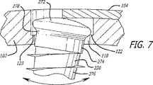
好ましくは、椎体係合固定具102は、上向面106から下向面108を通って延びる少なくとも1つの骨ねじ受け穴118を収容するように構成される。例えば、椎体係合固定具102の第1の端部110の幅を第2の端部112の幅よりも大きくして、一対の骨ねじ受け穴118を収容することができる。好ましくは、骨ねじ受け穴118は椎体の1つに重なるように構成され、椎体に係合する少なくとも1本の骨ねじ120を受けるように構成されて、椎体係合固定具102を椎体に取り付ける。好ましくは、骨ねじ受け穴118は、骨ねじが椎体係合固定具102を完全には通過しないように構成される。
Preferably, the vertebral
図5〜7に、限定ではなく例としてのみ示すように、骨ねじ受け穴118は椎体係合固定具102の下向面108近くで寸法が減少して、座部122を形成することができる。座部122は、挿入された骨ねじの少なくとも一部に接触するように構成された面123を有することができる。面123は、少なくとも一部が平面で、かつ少なくとも一部が湾曲し、または骨ねじの少なくとも一部に接触するのに適した他の構成を有することができる。好ましくは、骨ねじ受け穴118は1本の骨ねじを受けるように構成されるが、希望に応じて複数の骨ねじを受けるように構成してもよい。限定ではなく例としてのみ、骨ねじ受け穴は、少なくとも2本の骨ねじを受けるような大きさの長穴状である。骨ねじ受け穴118は、意図した目的のために十分な複数の方法で構成することができる。例えば、骨ねじ受け穴118と骨ねじとが螺合して、内部に受ける適切な寸法の骨ねじの後端部の少なくとも一部との締まり嵌めを形成することができる。骨ねじ受け穴118と骨ねじとが螺合して、骨ねじを椎体係合固定具102に固定保持し、または螺合して、例えば後述するように角度が可変となるように、骨ねじを椎体係合固定具102に対して可動にすることができる。骨ねじが椎体係合固定具に対して固定であることを希望するか可動であることを希望するかに応じて、同一の骨ねじ受け穴を異なる構成の骨ねじと螺合できることが理解できよう。限定ではなく例としてのみ、骨ねじ受け穴は円錐形であり、対応する形状のテーパ状頭部を有する骨ねじを挿入して骨ねじ受け穴との締まり嵌めを形成し、固定することができる。あるいは、丸い頭部を有する骨ねじを同一の円錐形骨ねじ受け穴に挿入して、可動となるようにし、骨ねじの可変角度位置決めを考慮する。
As shown by way of example and not limitation in FIGS. 5-7, the bone
椎体係合固定具102と接続平板104とは結合するように構成される。限定ではなく例としてのみ、椎体係合固定具102と接続平板104とは、図10aに示す留め具152または図10bおよび10cに示す留め具252等の留め具により、図21に示すような、詳細に後述する舌部・溝構成を介して結合される。
The vertebral
椎体係合固定具102と接続平板104とが留め具で結合される場合、各椎体係合固定具102は留め具受け開口を含むことができる。例えば、図4および10aは上向面106から下向面108を通って延び、詳細に後述する留め具152の一部を受ける留め具受け開口154を示す。留め具にねじ山がある場合、椎体係合固定具102の留め具受け開口154は、例えば留め具のねじ山に係合するように構成されたねじ山168を有するように構成することができる。留め具を留め具受け開口154に螺合することにより、接続平板104と椎体係合固定具102とを結合することができる。
When the vertebral
図1〜3および9に示すように、接続平板104は、上向面124、上向面124の反対側に、椎体側を向き、かつ椎体係合固定具102の上向面106の少なくとも一部に接触するように構成された下向面126、両側部128、130、および両端部132、134を有する。必要ではないが、好ましくは、接続平板104の上向面124および下向面126は、一般に人の脊椎の自然な湾曲に一致するように構成される。接続平板104の側部128、130は、椎体係合固定具102の凹部136の側部に係合するように構成することができる。例えば、接続平板104の側部128、130を傾斜させて、上向面124近くの接続平板104の幅を下向面126近くの接続平板104の幅よりも小さくし、凹部136の形状に対応させることができる。
As shown in FIGS. 1 to 3 and 9, the connecting
好ましくは、接続平板104の縦軸Lに沿った長さは、2つ以上の隣接する椎体の少なくとも一部に重なり、かつ椎体間の椎体腔に架け渡すのに十分な長さである。本発明の平板システムは、いくつかの隣接する椎体に架け渡すように構成することができ、この平板システムも本発明の広範な範囲に含まれることが理解できよう。例えば、図18および19は、単一の椎間腔にわたって使用され、頚椎の2つの隣接する椎体の少なくとも一部に重なるように構成される点を除いて、接続平板104と同様の接続平板204を有する平板システム200を示す。
Preferably, the length of the connecting
椎体係合固定具102と接続平板104とが留め具で結合される場合、接続平板104は、上向面124から接続平板104の下向面126を通って延び、留め具152を受けるように構成された少なくとも1つの留め具受け開口156を含むことができる。図1および2に示すように、好ましくは、接続平板104の留め具受け開口156は、留め具152が留め具受け開口156内で選択された移動をすることができるように、かつ椎体係合固定具102および接続平板104が接続平板104の縦軸に沿って選択された移動をすることができるように構成される。例えば、留め具受け開口156を楕円形とすることができ、または接続平板104の縦軸に沿って椎体係合固定具102を接続平板104に対して移動可能にするという意図した目的に適した他の形状とすることができる。留め具受け開口156は、留め具152の頭部が通過しないように構成される。例えば、接続平板104の留め具受け開口156は、留め具152の頭部の下面に接触するように構成された、接続平板104の上向面124から凹んだ肩部170を含むことができる。
When the vertebral
図1、2、9および10aに例を示すように、留め具を使用する好ましい実施形態では、留め具152は、接続平板102と少なくとも1つの椎体係合固定具104とを結合して両者の分離を制限するように構成される。図10aに示すように、留め具152は頭部158、軸160、およびねじ山162を有するねじ形状に具現化される。第1の位置では、留め具152は接続平板104に完全に締結されてはおらず、接続平板104の縦軸に沿って、かつ接続平板104の縦軸を横切る軸に沿って、椎体係合固定具102を接続平板104に対して移動させることができる。留め具152を別の位置に締結して、接続平板104と椎体係合固定具102との相対移動を、接続平板104の縦軸に沿った少なくとも1つの方向に限定することができる。
1, 2, 9, and 10a, in a preferred embodiment using a fastener, the
図10bおよび10cは、完全に締結したときにも、少なくとも1つの椎体係合固定具102に対して接続平板104が移動できるように構成された、留め具の別の好ましい実施形態を示す。留め具252は、接続平板104および椎体係合固定具102のうちの一方のみに締結されるように構成され、椎体係合固定具102と接続平板104との相対移動を可能にする。例えば、留め具252は、椎体係合固定具102を圧迫するように構成された肩部264を有することができる。肩部264は、頭部258と接続平板104との間に隙間166を生成して、留め具252が完全に締結されたときに椎体係合固定具102と接続平板104とが特定かつ所望の相対移動をすることができるような寸法を有する。
FIGS. 10 b and 10 c show another preferred embodiment of a fastener configured to allow the connecting
留め具を固締して、留め具受け開口154、156の一方または両方から留め具が抜けるのを防止することができる。例えば、接続平板104は、希望に応じて少なくとも1つの留め具を接続平板に固締するように構成された留め具固締要素を含むことができる。この固締要素は、接続平板104の留め具受け開口156内に少なくとも一部が配置されるように構成されたリングを含むことができる。あるいは、留め具固締要素は、開示を参照により本明細書中に組み込んだ、米国特許第6139550号('550号特許)のMichelsonによる骨ねじに関して記載されたものと同様の方法で、1つまたは複数の留め具の少なくとも一部を覆うように構成することができる。
The fasteners can be secured to prevent the fasteners from being removed from one or both of the
留め具は椎体係合固定具102を接続平板104に結合するのに必要なものではないことが理解できよう。他の方法、装置、および/または椎体係合固定具および接続平板の他の構成を使用して、椎体係合固定具102と接続平板104とを結合することができる。
It will be appreciated that the fasteners are not necessary to couple the vertebral
例として、図21〜23は、舌部・溝構成内で結合された椎体係合固定具602および接続平板604の別の好ましい実施形態を示す。例として、接続平板604は、接続平板604の縦軸を横切る横断面を持つ部分、すなわちC字形成溝680を有することができる。接続平板604は各側部に沿って少なくとも1つのタブ682を有する。好ましくは、複数のタブ682が接続平板604の側部に沿って離間している。椎体係合固定具602は、椎体係合固定具602の縦軸を横切る横断面を持つ部分、すなわちT字形成側部684を有することができる。椎体係合固定具602は、接続平板604のC字形横断面に係合して、側部684がC字形成溝680にそれぞれ係合するように構成される。椎体係合固定具602の側部684は、接続平板604の少なくとも1つのタブ682が通過できるように構成されたノッチ686を含む。使用時には、接続平板604が椎体係合固定具602上に配置されて、タブ682が対応するノッチ686に整合して側部684を溝680に摺動可能に係合させ、椎体係合固定具602と接続平板604とを結合する。椎体係合固定具の少なくとも1つが、接続平板の溝で受けるように構成された横断面を持つ舌部として構成された部分を有するように、椎体係合固定具および接続平板を構成してもよいことが理解できよう。
By way of example, FIGS. 21-23 illustrate another preferred embodiment of a vertebral
好ましくは、接続平板104の少なくとも一部が椎体係合固定具102の少なくとも1つの少なくとも一部に嵌合して、隣接する椎体が「ダイナミゼーション」するように、すなわち、椎体係合固定具が椎体に取り付けられて接続平板により接続された後に椎体同士が移動するように構成される。ダイナミゼーションが「受動」の場合、圧縮負荷等の短縮力の印加時に、椎体係合固定具間の間隔を短縮することができる。ダイナミゼーションが「能動」の場合、平板システムは、エネルギーを蓄積して平板システム構成全体を短縮する。本発明の平板システムは、受動ダイナミゼーションし、能動ダイナミゼーションし、両者を組み合わせ、かつ完全に後述するように、治癒段階中に発生する、ある圧縮応力を変換かつ蓄積する。
Preferably, at least a portion of the connecting
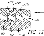
例えば、図4、8、11および12に示すように、接続平板104の下向面126の少なくとも一部および椎体係合固定具102の上向面106の少なくとも一部は、嵌合して、接続平板104の縦軸に沿った選択された連続移動が可能になるように構成されたラチェッティング146等の面構成を含むことができる。好ましくは、ラチェッティングを偏倚させて、接続平板の縦軸に沿った1つの好ましい方向への移動を可能にして、接続平板104の縦軸に沿った第1の方向へ椎体係合固定具102同士が移動できるようにし、かつ第1の方向に反する方向への移動に抵抗するようにする。
For example, as shown in FIGS. 4, 8, 11 and 12, at least a portion of the
図11および12は、単一の方向への移動を可能にする前向き構成を有するラチェッティング146の好ましい実施形態を示す。椎体係合固定具102同士の移動が必要な場合にラチェッティング146の構成は有用であり、椎体係合固定具102間の間隔をさらに短縮することができる。ラチェッティング146の三角形断面の好ましい角度関係は、30−60−90度の三角形の関係である。図12に示すように、ラチェッティング146が前向き角であるため、矢印で示す、接続平板104の縦軸に沿った方向への椎体係合固定具102および接続平板104の摺動が、傾斜面148により促進される。逆に、反対方向への摺動は縦壁150により制限される。椎体係合固定具102および接続平板104の移動は、ラチェッティング146により、かつ接続平板104の縦軸を横切る軸に沿った椎体係合固定具102と接続平板104との分離を制限することにより、単一の方向に限定される。
FIGS. 11 and 12 illustrate a preferred embodiment of a ratcheting 146 having a forward-facing configuration that allows movement in a single direction. The configuration of the ratcheting 146 is useful when movement between the vertebral
椎体係合固定具102と接続平板104とを相対移動させるためには、ラチェッティング146の頂部高さが触れないように接続平板104と椎体係合固定具102とが離れるのに十分な運動の自由度を設ける必要がある。この運動の自由度を達成する1つの方法は、例えば前記の舌部・溝構成内で、舌部と溝との間に十分な間隔をおいて椎体係合固定具102と接続平板104とを結合して、接続平板104と椎体係合固定具102とが離れてラチェッティング146の頂部同士が触れないようにすることを含む。椎体係合固定具102と接続平板104の縦の曲率をわずかに異ならせて、結合時に椎体係合固定具102と接続平板104とが跳ね返って離れるようにしてもよい。例えば、接続平板104の下面126の曲率半径を、椎体係合固定具102の上面106の曲率半径と異ならせることができる。
In order to move the vertebral
ラチェッティング146の頂部高さが触れないように接続平板104と椎体係合固定具102とが離れるのに十分な運動の自由度を達成する別の方法は、少なくとも1つの留め具を使用して椎体係合固定具102と接続平板104とを結合し、かつ選択的に締結することを含む。例えば、留め具152は接続平板104に完全に締結されてはおらず、接続平板104の縦軸に沿って、かつ接続平板104の縦軸を横切る軸に沿って、ラチェッティング146同士が離れることができるように椎体係合固定具102および接続平板104を移動させることができる。その後、留め具152を別の位置に締結して、例えば接続平板104の留め具受け開口156の形状を使用して、接続平板104の縦軸に沿った少なくとも1つの方向への接続平板104と椎体係合固定具102との相対移動に抵抗し、またはこの相対移動を制限する。
Another way of achieving sufficient freedom of movement for the connecting
例えば、少なくとも2つの椎体係合固定具102同士が接続平板104に対して接続平板104の縦軸に沿って互いの方向へ移動するのを促進し、かつ少なくとも2つの椎体係合固定具102同士が接続平板104の縦軸に沿って離れる方向へ移動するのに抵抗し、またはこの移動を制限するように構成された第1の位置に、留め具152を締結することができる。したがって、2つの隣接する椎体間の間隔が減少すれば、接続平板104の据付け後であっても2つの椎体係合固定具102間の間隔を短縮することができるので、椎体は接続平板104および椎体係合固定具102によって離した状態で保持されることがなく、偽関節の発生が防止される。
For example, the at least two vertebral
本発明の好ましい実施形態では、ばね力を加えて、接続平板104が椎体係合固定具102の少なくとも1つから離れるのを制御し、接続平板104に沿って椎体係合固定具102同士が離れる移動に抵抗する。図10cに示すように、例として、留め具252の頭部258との間に配置されてばね圧力を接続平板104に加えるように構成されたばね座金270と共に、留め具252を使用することができる。留め具252の頭部258の下部に形成された溝272でばね座金270を保持することができる。
In a preferred embodiment of the present invention, a spring force is applied to control the
別の例として、留め具252の頭部は、接続平板104が椎体係合固定具102の少なくとも1つから離れるのを制御するばね力を加えるように構成される。例えば、接続平板104に接触するように構成された留め具252の頭部下面の少なくとも一部は、可撓性のある凹状であり、かつ/またはばね座金270と同様の構成を有する。
As another example, the head of the
別の実施形態では、接続平板104の下向面の曲率と椎体係合固定具102の上向き面の曲率とがわずかに異なる。異なる湾曲部は互いに係合して、接続平板104と椎体係合固定具102とが離れるのに抵抗する。
In another embodiment, the downward curvature of the connecting
接続平板104および椎体係合固定具102の十分な運動の自由度を達成して、結合したまま離した状態にする他の方法があり、この方法も本発明の広範な範囲に含まれることを当業者なら理解できよう。
There are other ways of achieving sufficient freedom of movement of the connecting
能動ダイナミゼーションを希望する場合、ラチェッティング146の前向き構成を使用して、隣接する椎体間の椎間板腔にわたる圧縮負荷を蓄積かつ維持することができる。蓄積された圧縮負荷は外科医により加えることができ、かつ/または治癒段階中に首の運動に伴って任意に生じる圧縮負荷により加えることができる。例えば、外科医は、2つ以上の椎体係合固定具102同士を移動することにより、所望量の「前負荷」、すなわち平板取付け後の癒合部位にわたる圧縮力を発生させて、希望に応じて平板システムの全体構成の長さを短縮することができる。隣接する椎体間の圧縮負荷を維持し、かつ癒合過程中に、壊死した骨が新生骨に交換されるときに隙間が広がる可能性を減らすことによって、前負荷の発生により癒合が促進される。
If active dynamization is desired, a forward-facing configuration of ratcheting 146 can be used to accumulate and maintain a compressive load across the intervertebral disc space. The accumulated compressive load can be applied by the surgeon and / or by a compressive load that optionally accompanies the neck movement during the healing phase. For example, a surgeon can move between two or more vertebral
図20に示すように、限定ではなく例としてのみ、癒合部位にわたって圧縮負荷を発生させるために、椎体係合固定具を圧縮器具300に係合するように構成することができる。圧縮器具300を使用して、隣接する椎体の各々に取り付けられた椎体係合固定具102同士を移動させて、癒合すべき椎間板腔にわたって圧縮負荷を加えることができる。圧縮負荷が加わると、接続平板104は椎体係合固定具102に十分に締結されるので、希望に応じて、椎体係合固定具102同士を接続平板104の縦軸に沿ってのみ移動させることができ、または椎体係合固定具102をさらに締結して、椎体係合固定具102が接続平板104に対して移動するのを防止することができる。
As shown in FIG. 20, by way of example and not limitation, the vertebral body engagement fixture can be configured to engage the
あるいは、接続平板104および/または椎体係合固定具102は、例えば、参照により本明細書中に組み込んだ、米国特許第6193721号('721号特許)のMichelsonにより教示されたもの等の、圧縮器具の少なくとも一部が接続平板104を通過して下にある椎体に係合するように構成された更なる開口を含むことができる。
Alternatively, connecting
本発明の別の好ましい実施形態では、平板システムはダイナミゼーションに備える必要がない。例えば、留め具152の締結後に接続平板104および椎体係合固定具102を移動することを希望しない場合には、ラチェッティングを45−45−90度の三角形に構成することができる。したがって、留め具152を第2の位置に締結して、接続平板104の縦軸の少なくとも一部に沿った接続平板104と椎体係合固定具102との相対移動を完全に制限することができる。
In another preferred embodiment of the invention, the flat plate system need not be prepared for dynamization. For example, if it is not desired to move the connecting
骨ねじを椎間板腔に固締して、希望に応じて、例えば骨ねじを物理的に遮って抜けを防ぐことにより、骨ねじ受け穴からの好ましくない緩みや抜けを防止することができる。例えば、図1、2、5〜7および9に示すように、接続平板104を椎体係合固定具102に結合したときに、接続平板104の一部が骨ねじ受け穴118の少なくとも1つの少なくとも一部を覆うように構成することができ、かつ挿入された骨ねじ120の少なくとも一部を覆うことができる。図9に示すように骨ねじ受け穴118が並んだ向きにある場合には、接続平板104は、骨ねじ120を内部に固締する一対の骨ねじ受け穴118の少なくとも一部を覆うように構成される。例えば、接続平板104は、椎体係合固定具102の凹部136内へ摺動またはスナップ嵌めすることにより骨ねじ受け穴118を覆って、図9〜10cに示すような1つまたは複数の骨ねじ受け穴の少なくとも一部を覆うことができる。
By tightening the bone screw in the intervertebral disc space and, if desired, for example, physically blocking the bone screw to prevent removal, undesired loosening or removal from the bone screw receiving hole can be prevented. For example, as shown in FIGS. 1, 2, 5-7 and 9, when the connecting
骨ねじを固締するための他の方法、装置、および/または構成もあり、これらも本発明の広範な範囲に含まれる。例えば、骨ねじの1本のみを椎体係合固定具102の1つに固締することを希望する場合、適切な骨ねじ固締具は、ねじ、リベット、キャップ、またはカバーの形状である。当業者に公知の、骨ねじの1本を固定するための固締要素も本発明の範囲に含まれることが理解できよう。あるいは、多固締骨ねじ固締具を使用して、希望に応じて、少なくとも2本の骨ねじを1つの椎体係合固定具102に固締することができる。単固締骨ねじ固締具および多固締骨ねじ固締具の例は、'550号特許でMichelsonにより教示されており、これらを使用して、1本の骨ねじまたは複数の骨ねじが、挿入された対応する骨ねじ受け穴から抜けるのを防止することができる。
There are other methods, devices, and / or configurations for fastening bone screws, which are also within the broad scope of the present invention. For example, if it is desired to secure only one of the bone screws to one of the vertebral
図5〜7は本発明で使用可能な骨ねじの例を示す。骨ねじは、各骨ねじ受け穴に固定または可動に係合するように構成される。骨ねじが椎体係合固定具に対して固定であることを希望するか可動であることを希望するかに応じて、同一の骨ねじ受け穴を異なる構成の骨ねじと螺合できることが理解できよう。限定ではなく例としてのみ、図5は、頭部172、頭部172に近接した肩部174、および頚椎に挿入されるように構成された前端部を持つ軸176を有する骨ねじ120を示す。好ましくは、頭部172は椎体係合固定具102の少なくとも1つに固定されるように構成される。例えば、頭部172の頂部はほぼ平面状に構成されて、接続平板102の一部または他の骨ねじ固締具により覆われたときに、例えば接続平板102が、骨ねじ受け穴118内で骨ねじ120が実際に移動するのを防止する。骨ねじ受け穴118の縦側壁は頭部172の縦側壁に係合して、締まり嵌めを形成している。頭部172と肩部174との間の接合部178は、一般に正方形とすることができる。
5-7 show examples of bone screws that can be used in the present invention. The bone screw is configured to be fixedly or movably engaged with each bone screw receiving hole. It is understood that the same bone screw receiving hole can be screwed with differently configured bone screws depending on whether the bone screw is desired to be fixed or movable relative to the vertebral body engaging fixture I can do it. By way of example and not limitation, FIG. 5 shows a
図6および7に示すように、本発明の椎体係合固定具は、匍匐置換過程の吸収段階の発生時に、椎骨を離した状態に維持するのではなく、椎骨を骨移植片等の介在する癒合構成に向かって移動させ、かつ必要であれば椎骨同士を移動させることのできる骨ねじシステムを含む。例えば、骨ねじ220は、接続平板104等の固締具または他の固締具で骨ねじが覆われたときに骨ねじ220が骨ねじ受け穴118内で移動できるように構成された、一般に丸い頂部を有する頭部272を含む。骨ねじ220は、頭部272と肩部274との間に、一般に丸い接合部278をさらに含み、骨ねじ220が椎体係合固定具102の少なくとも1つの骨ねじ受け穴118に対して可動に、例えば角度が可変となるようにする。他のねじ・平板・固締具システムを使用することもでき、これらも本発明の広範な範囲に含まれる。例えば、'550特許は、組み合わせ可能な3つのタイプのねじ・平板・固締具システム、すなわち(1)受動ダイナミゼーションタイプ、(2)自己圧縮タイプ、および(3)能動ダイナミゼーションタイプを開示している。
As shown in FIGS. 6 and 7, the vertebral body engaging and fixing device of the present invention does not maintain the vertebra in a separated state when the resorption stage of the heel replacement process occurs, but interposes the vertebra with a bone graft or the like. It includes a bone screw system that can be moved toward the healing configuration to be moved and, if necessary, vertebrae can be moved together. For example, the
図13および14は、本発明による据付け時に、椎体係合固定具を位置決め、整合、かつ/または保持するための整合器具の好ましい実施形態を示し、この整合器具全体を符号400で示す。好ましくは、整合器具400を使用して、本発明の平板システムを3つ以上の隣接する椎体および椎体間の椎間腔に当てる。整合器具400は、上向面402、下向面404、前端部406、および両側部408、410を含む。好ましい実施形態では、所望の位置に整合器具を位置決めし、かつ保持するのに使用するハンドル430が、上向面402から延びている。好ましくは、整合器具400は、少なくとも1つの椎体係合固定具102に係合するように構成されている。例えば、好ましくは、下向面404は、椎体係合固定具102の留め具受け開口154に嵌入するような大きさに構成された係合釘412を含む。係合釘412は、係合釘412の中心縦軸から外側に偏倚した複数の弾性部分414を有して、椎体係合固定具102の留め具受け開口154に取り付けられているときに椎体係合固定具102を把持し、かつ保持するように構成される。
FIGS. 13 and 14 illustrate a preferred embodiment of an alignment device for positioning, aligning and / or holding a vertebral body engagement fixture during installation according to the present invention, and this alignment device is generally designated 400. Preferably, the
好ましくは、両側部408、410は、整合器具400が椎体係合固定具102に係合しているときに骨ねじを骨ねじ受け穴に挿入できるように構成された外形を、各側部の長さの少なくとも一部に沿って有する。例えば各側部408、410は、整合器具400が椎体係合固定具102に係合しているときに、骨ねじ受け穴の外周にほぼ対応するように構成された円弧状部分416を有する。好ましくは、各円弧状部分416は、係合釘412の中心縦軸と前端部406との間の間隔が、円弧状部分416の中点と前端部406との間隔よりも小さくなるように、各側部408、410の長さの一部に沿って配置される。この構成は、例えば、前端部406を椎体係合固定具102の第2の端部112に対向するように構成する場合に適している。
Preferably, both
整合器具400を使用して、癒合すべき各椎体の所望の位置に複数の椎体係合固定具102を配置し、整合させることができる。例えば、整合器具400を使用して、第1の椎体係合固定具102を第1の椎体に配置することができる。整合器具400を使用して、第2の椎体係合固定具102を第1の椎体に隣接する椎体に配置することができる。整合器具400を使用して、第2の椎体係合固定具102を第1の椎体係合固定具102に整合させて、接続平板104に合わせることができる。
Using the
椎体係合固定具102を整合器具400により各椎体に保持したまま、各椎体係合固定具102の骨ねじ受け穴118を通して椎体に穴を形成することができる。次いで、骨ねじ120を骨ねじ受け穴118に挿入して、各椎体係合固定具102を各椎体に固定することができる。好ましくは、第1の椎体係合固定具102を第1の椎体に固定した後、第2の椎体係合固定具を他の椎体に配置し整合させる。整合器具400を椎体係合固定具から取り外し、接続平板104を椎体係合固定具上に配置する。好ましくは、椎体係合固定具と接続平板とを結合するための前記の方法および/または椎体係合固定具および接続平板の構成の1つを使用して、接続平板を各椎体係合固定具に結合する。平板システムに前負荷を加えることを希望する場合、圧縮器具300等の適切な圧縮器具により癒合部位にわたって圧縮負荷を加えることができる。これにより接続平板104が椎体係合固定具102に対して十分に締結されるので、椎体係合固定具102同士を、例えば接続平板104の縦軸に沿ってのみ移動させることができ、または椎体係合固定具102をさらに締結して椎体係合固定具102が接続平板104に対して移動するのを防止することができる。
While the vertebral
意図した目的で働くように接続平板に係合可能な器具は、本発明の装置および方法の範囲に含まれる。例としてのみ、平板に結合された骨ねじ受け穴に同軸に整合する椎体の骨ねじ受け穴を形成する、パイロット穴形成パンチを含む、平板を頚椎に据え付けるための方法および装置が、'721特許でMichelsonにより教示され記載される。 Instruments that are engageable with the connecting plate to serve the intended purpose are within the scope of the apparatus and method of the present invention. By way of example only, a method and apparatus for mounting a flat plate to a cervical spine including a pilot hole forming punch that forms a bone screw receiving hole in a vertebral body coaxially aligned with a bone screw receiving hole coupled to the flat plate is' 721. Patent taught and described by Michelson.
図15〜17は、本発明による、据付け時に椎体係合固定具を位置決め、整合、かつ保持するための整合器具の別の好ましい実施形態を示し、この整合器具全体を符号500で示す。整合器具500は整合器具400に類似しており、好ましくは、本発明の平板システムを2つの隣接する椎体および椎体間の椎間腔に当てる。好ましい実施形態では、所望の位置に整合器具を位置決めし、かつ保持するのに使用するハンドル530が、上向面502から延びている。好ましくは、整合器具500は、係合釘512の中心縦軸と前端部506との間の間隔が、各円弧状部分516の中点と前端部506との間隔よりも大きくなるように、各側部508、510の長さに沿って配置された各円弧状部分516を有する。この構成は、例えば、前端部506を椎体係合固定具102の第1の端部110に対向するように構成する場合に適している。椎体係合固定具102を整合、位置決め、かつ保持するための他の器具も可能であり、本発明の広範な範囲に含まれることが理解できよう。限定ではなく例としてのみ、このような器具が、参照により本明細書中に組み込んだ'721特許および'550特許でMichelsonにより教示されている。
FIGS. 15-17 illustrate another preferred embodiment of an alignment device for positioning, aligning, and holding a vertebral body engagement fixture in accordance with the present invention, generally designated 500. The
本発明の好ましい実施形態について、前頚椎での好ましい使用に関して説明した。本発明を胸椎または腰椎の前部でも使用できることが理解できよう。
本明細書中に記載した平板システムの実施形態は、骨形成の材料、癒合促進物質、骨成長促進材料、骨由来物質または生成物、脱塩骨基質、鉱化タンパク質、骨化タンパク質、骨形成タンパク質、ヒドロキシアパタイト、骨生成のための遺伝子コーディング、少なくとも一部が骨以外である物質、および限定されないが皮膚骨を含む骨から作ることができ、これらで処理することができ、これらで被覆することができ、これらと組み合わせることができ、これらから構成することができ、またはこれらと共に使用することができることが理解できよう。椎体係合固定具、接続平板、ねじ、留め具、および/またはねじ固締具を、瘢痕形成を抑制する材料と組み合わせることもできる。椎体係合固定具、接続平板、ねじ、留め具、および/またはねじ固締具を、抗菌材料と組み合わせることができ、または抗菌材料を含むことができ、かつ/または、例えば銀被覆により、抗菌性を与えるように表面処理または表面被覆することができる。好ましくは、椎体係合固定具の底面の少なくとも一部は、多孔および/またはテクスチャ面を有し、かつ癒合促進物質(骨形成タンパク質等)で被覆され、この物質を含浸し、またはこの物質を含んで、骨部に架け渡した平板の下面に沿った骨の成長を促進するようになっている。テクスチャ加工された底面は、据付け前に底面層に含浸させることのできる癒合促進物質を保持する媒体を提供する。粗いブラスティング、またはエッチング、プラズマ溶射、焼結、鋳造等の他の従来の技術により、椎体係合固定具の底面を所望の多孔テクスチャ形状にすることができる。骨内殖を促進するために多孔にする場合、底面は約50〜500ミクロン、好ましくは100〜300ミクロンの多孔率または孔径を有するように形成される。多孔テクスチャ底面が含浸可能な骨成長促進物質は、限定されないが、骨形成タンパク質、ヒドロキシアパタイト、またはヒドロキシアパタイトリン酸三カルシウムを含む。椎体係合固定具、接続平板、ねじ、留め具、および/または骨ねじ固締具は、骨成長材料をさらに含浸させることのできる吸収性材料または生体吸収性材料を少なくとも一部に含み、吸収性材料または生体吸収性材料が患者の体内で吸収されると、骨成長材料が放出され、持続放出機構として働く。生体吸収性材料は、例えば、少なくとも一部が骨以外である。本発明の平板システムを、材料に関係なく、脊椎の一部に挿入可能な物体等の脊椎固定インプラントと組み合わせて使用することができる。脊椎固定インプラントは、限定されないが、椎体間脊椎インプラント、椎体間脊椎癒合インプラント、構造骨移植片、メッシュ、ケージ、スペーサ、ステープル、骨ねじ、平板、棒、人工索またはワイヤの繋ぎ、あるいは他の脊椎固定金具等である。椎体間脊椎癒合インプラントは、少なくとも一部が骨で構成される。椎体間脊椎癒合インプラントは、例えば、同種移植片の椎体間骨移植片インプラント、または人工インプラントである。希望に応じて、骨成長を刺激して骨癒合に寄与するために、椎体係合固定具、接続平板、および留め具の少なくとも1つに通電することができる。
Preferred embodiments of the present invention have been described with respect to preferred use in the anterior cervical spine. It will be appreciated that the present invention can also be used on the front of the thoracic or lumbar spine.
Embodiments of the flat plate system described herein include bone forming materials, fusion promoting materials, bone growth promoting materials, bone derived materials or products, demineralized bone matrix, mineralized proteins, ossified proteins, bone formation. Proteins, hydroxyapatite, gene coding for bone generation, materials that are at least partially non-bones, and can be made from and treated with bone including but not limited to skin bone It will be appreciated that they can be combined with, composed of, or used with them. Vertebral engagement fixtures, connecting plates, screws, fasteners, and / or screw fasteners can also be combined with materials that inhibit scar formation. Vertebral engagement fixtures, connecting plates, screws, fasteners, and / or screw fasteners can be combined with or include antimicrobial material and / or, for example, by silver coating, Surface treatment or surface coating can be applied to provide antibacterial properties. Preferably, at least a portion of the bottom surface of the vertebral body engaging fixture has a porous and / or textured surface and is coated with, impregnated with, or impregnated with a substance that promotes fusion (such as bone morphogenetic protein). The bone growth along the lower surface of the flat plate spanning the bone portion is promoted. The textured bottom surface provides a medium that holds a fusion promoting material that can be impregnated into the bottom layer prior to installation. Rough blasting, or other conventional techniques such as etching, plasma spraying, sintering, casting, etc., can allow the bottom surface of the vertebral body engagement fixture to have the desired porous texture shape. When made porous to promote bone ingrowth, the bottom surface is formed to have a porosity or pore size of about 50-500 microns, preferably 100-300 microns. Bone growth promoting materials that can be impregnated in the porous texture bottom include, but are not limited to, bone morphogenetic proteins, hydroxyapatite, or hydroxyapatite tricalcium phosphate. The vertebral body engaging fixture, connecting plate, screw, fastener, and / or bone screw fastener includes at least in part an absorbable or bioabsorbable material that can be further impregnated with a bone growth material, When the resorbable material or bioabsorbable material is absorbed in the patient's body, the bone growth material is released and acts as a sustained release mechanism. For example, at least a part of the bioabsorbable material is other than bone. The flat plate system of the present invention can be used in combination with a spinal fixation implant, such as an object that can be inserted into a portion of the spine, regardless of the material. Spinal fusion implants include, but are not limited to, interbody spinal implants, interbody spinal fusion implants, structural bone grafts, meshes, cages, spacers, staples, bone screws, plates, rods, artificial ropes or wire tethers, or Other spinal fixtures and the like. The interbody spinal fusion implant is at least partially composed of bone. The interbody spinal fusion implant is, for example, an allograft interbody bone graft implant or an artificial implant. If desired, at least one of the vertebral body engagement fixture, the connecting plate, and the fastener can be energized to stimulate bone growth and contribute to bone healing.
本明細書および本明細書中に開示した本発明の実施を考慮すれば、本発明の他の実施形態が当業者に明らかになろう。本明細書および例は単に例示的なものとして考慮されており、本発明の真の範囲および精神は頭記の請求の範囲によって示される。 Other embodiments of the invention will be apparent to those skilled in the art from consideration of the specification and practice of the invention disclosed herein. It is intended that the specification and examples be considered as exemplary only, with a true scope and spirit of the invention being indicated by the following claims.
図10bは、本発明による、接続平板を椎体係合固定具に取り付け、かつ接続平板と椎体係合固定具との所望量の相対移動を可能にする留め具の別の実施形態を示す、図9の線10a−10aに沿った拡大横断面図である。
FIG. 10b shows another embodiment of a fastener according to the present invention for attaching a connecting plate to a vertebral body engaging fixture and allowing a desired amount of relative movement between the connecting plate and the vertebral body engaging fixture. FIG. 10 is an enlarged cross-sectional view taken along
図10cは、図10bの拡大切欠図である。
Claims (25)
癒合すべき隣接する椎体の一方に取り付けられるように構成された少なくとも第1の椎体係合固定具と、癒合すべき隣接する椎体の他方に取り付けられるように構成された少なくとも第2の椎体係合固定具とを含み、前記第1の椎体係合固定具および第2の椎体係合固定具は各々、椎体の1つに接触するように構成された下向面と、前記下向面に対向する少なくとも1つの上向面と、前記上向面から前記下向面を通って延びる少なくとも1つの骨ねじ受け穴とを有し、前記骨ねじ受け穴の各々は、椎体の1つに重なり、かつ椎体に係合する少なくとも1本の骨ねじを受けるように構成されて、前記少なくとも第1の椎体係合固定具および第2の椎体係合固定具の各々を頚椎に取り付け、前記第1の椎体係合固定具および第2の椎体係合固定具の各々は、人の脊椎の縦軸に沿った向きに構成された両端部を有し、前記第1の椎体係合固定具および第2の椎体係合固定具の各々は、両側部を有し、
前記平板システムは、また、
前記第1の椎体係合固定具と第2の椎体係合固定具とを接続するように構成された接続平板を含み、前記接続平板は、前記第1の椎体係合固定具および第2の椎体係合固定具の各々の少なくとも一部に重なるように構成され、椎体側を向くように構成された下向面と、前記下向面に対向する上向面とを有し、前記上向面は第1上向面部分と第2上向面部分とを有し、前記第1上向面部分と第2上向面部分とは異なる平面にあり、前記接続平板は両端および該両端間の長手軸線を有し、前記接続平板の下向面はその長手軸線の少なくとも一部に沿った方向で凹んでおり、かつ前記接続平板の前記上向面から前記下向面を通って延びる少なくとも1つの留め具受け開口を有し、前記留め具受け開口は、留め具を受けて、前記接続平板を前記第1の椎体係合固定具および第2の椎体係合固定具の少なくとも1つに取り付けるように構成され、
前記平板システムは、更に
少なくとも2つの留め具を含み、前記留め具は各々、前記接続平板と前記第1の椎体係合固定具および第2の椎体係合固定具の一方とを結合するように構成されており、前記各留め具は、頭部及び軸を有し、該軸は前記第1の椎体係合固定具および第2の椎体係合固定具の一方に係合するようになっており、前記頭部は上向面および少なくとも1つの下向面を有し、前記頭部の少なくとも一つの下向面は、前記接続平板と前記第1、第2の椎体係合固定具の一方とが結合するとき、前記頭部の上向面が前記接続平板の第1の上向面部分の上方へ延びることなしに前記接続平板の第2上向面部分と接触する、平板システム。A flat plate system configured to contact the anterior surface of a human cervical vertebra and contacting the anterior surfaces of at least two adjacent cervical vertebral bodies to be fused;
At least a first vertebral body engaging fixture configured to be attached to one of the adjacent vertebral bodies to be fused, and at least a second configured to be attached to the other of the adjacent vertebral bodies to be fused. A vertebral body engaging fixture, wherein the first vertebral body engaging fixture and the second vertebral body engaging fixture each have a downwardly facing surface configured to contact one of the vertebral bodies. , At least one upward surface opposite the downward surface, and at least one bone screw receiving hole extending from the upward surface through the downward surface, wherein each of the bone screw receiving holes comprises: The at least first vertebral body engaging fixture and the second vertebral body engaging fixture configured to receive at least one bone screw that overlaps and engages one of the vertebral bodies. Each of the first vertebral body engaging fixture and the second vertebral body engaging fixture Each has opposite ends configured along the longitudinal axis of the human spine, and each of the first vertebral body engaging fixture and the second vertebral body engaging fixture has sides. Have
The flat plate system also includes
A connecting flat plate configured to connect the first vertebral body engaging fixture and the second vertebral body engaging fixture, the connecting flat plate comprising the first vertebral body engaging fixture and A downward surface configured to overlap at least a part of each of the second vertebral body engaging fixtures and configured to face the vertebral body side, and an upward surface facing the downward surface and, wherein the upward surface and a first upstream surface portion and a second upwardly surface section lies in a plane that is different from the first upward surface portion and a second upward surface portions, the connecting flat plate has a longitudinal axis between both ends and the both ends, the downward surface of the connection flat plate is recessed in a direction along at least a portion of its longitudinal axis, and the lower from the upward surface of the connecting flat At least one fastener receiving opening extending through the facing surface, wherein the fastener receiving opening receives the fastener and connects the connecting plate to the first. Configured for attachment to at least one body engaging fastener and the second vertebral body engaging fastener,
The plate system further includes at least two fasteners, each of the fasteners coupling the connecting plate and one of the first vertebral body engaging fixture and the second vertebral body engaging fixture. Each fastener has a head and a shaft that engages one of the first vertebral body engaging fixture and the second vertebral body engaging fixture. The head has an upward surface and at least one downward surface, and the at least one downward surface of the head has the connection plate and the first and second vertebral body members. When one of the fittings is coupled, the upward surface of the head contacts the second upward surface portion of the connection plate without extending above the first upward surface portion of the connection plate. , Flat plate system.
癒合すべき隣接する椎体の一方に取り付けられるように構成された少なくとも第1の椎体係合固定具と、癒合すべき隣接する椎体の他方に取り付けられるように構成された少なくとも第2の椎体係合固定具とを含み、前記第1の椎体係合固定具および第2の椎体係合固定具は各々、椎体の1つに接触するように構成された下向面と、前記下向面に対向する少なくとも1つの上向面と、前記上向面から前記下向面を通って延びる少なくとも1つの骨ねじ受け穴とを有し、前記骨ねじ受け穴の各々は、椎体の1つに重なり、かつ椎体に係合する少なくとも1本の骨ねじを受けるように構成されて、前記少なくとも第1の椎体係合固定具および第2の椎体係合固定具の各々を頚椎に取り付け、前記第1の椎体係合固定具および第2の椎体係合固定具の各々は、人の脊椎の縦軸に沿った向きに構成された両端部を有し、前記第1の椎体係合固定具および第2の椎体係合固定具の各々は、両側部を有し、
前記第1の椎体係合固定具と第2の椎体係合固定具とを接続するように構成された接続平板をさらに含み、前記接続平板は、前記第1の椎体係合固定具および第2の椎体係合固定具の各々の少なくとも一部に重なるように構成され、椎体側を向くように構成された下向面と、前記下向面に対向する上向面とを有し、かつ前記接続平板の前記上向面から前記下向面を通って延びる少なくとも1つの留め具受け開口を有し、前記留め具受け開口は、留め具を受けて、前記接続平板を前記第1の椎体係合固定具および第2の椎体係合固定具に取り付けるように構成され、
平板システムが更に、少なくとも2つの固定具を有し、これら各固定具が、前記接続平板と前記第1、第2の椎体係合固定具の一方と一緒に結合するようになっており、前記固定具の少なくとも1つは頭部および軸を有し、前記軸は前記第1、第2の椎体係合固定具の一方に係合するようになっており、前記頭部は第1部分と第2部分とを有し、該第1部分が前記固定具の長手軸線を横断する前記第2部分より大きな寸法を有し、前記頭部の第1部分および第2部分が各々下向面を有し、前記固定具の少なくとも一つが、前記軸が前記第1、第2の椎体係合固定具の前記一方に係合する第1位置を有し、前記頭部の第2部分の下向面は、前記第1、第2の椎体係合固定具の一方の上向面と接触し、前記頭部の第1部分の下向面は、前記接続平板の上向面から離れており、少なくとも1つの固定具の第1位置は、前記接続板の長手軸線に沿って互いの方へ前記接続平板に対する前記第1、第2の椎体係合固定具の少なくとも一方の動きを容易にし、且つ前記接続平板の長手軸線に沿って互いに離れる方向へ前記第1、第2の椎体係合固定具の少なくとも一方の動きの抵抗になるようになっている、平板システム。A flat plate system configured to contact the anterior surface of a human cervical vertebra and contacting the anterior surfaces of at least two adjacent cervical vertebral bodies to be fused;
At least a first vertebral body engaging fixture configured to be attached to one of the adjacent vertebral bodies to be fused, and at least a second configured to be attached to the other of the adjacent vertebral bodies to be fused. A vertebral body engaging fixture, wherein the first vertebral body engaging fixture and the second vertebral body engaging fixture each have a downwardly facing surface configured to contact one of the vertebral bodies. , At least one upward surface opposite the downward surface, and at least one bone screw receiving hole extending from the upward surface through the downward surface, wherein each of the bone screw receiving holes comprises: The at least first vertebral body engaging fixture and the second vertebral body engaging fixture configured to receive at least one bone screw that overlaps and engages one of the vertebral bodies. Each of the first vertebral body engaging fixture and the second vertebral body engaging fixture Each has opposite ends configured along the longitudinal axis of the human spine, and each of the first vertebral body engaging fixture and the second vertebral body engaging fixture has sides. Have
The apparatus further includes a connecting plate configured to connect the first vertebral body engaging fixture and the second vertebral body engaging fixture, wherein the connecting plate is the first vertebral body engaging fixture. A downward surface configured to overlap at least a part of each of the second vertebral body engaging fixtures and configured to face the vertebral body side, and an upward surface opposite to the downward surface And having at least one fastener receiving opening extending from the upward surface of the connecting plate through the downward surface, the fastener receiving opening receiving the fastener, and connecting the connecting plate to the connecting plate. Configured to attach to the first vertebral body engaging fixture and the second vertebral body engaging fixture;
The plate system further comprises at least two fixtures, each of which is coupled together with one of the connecting plate and the first and second vertebral body engaging fixtures; At least one of the fixtures has a head and a shaft, the shaft being adapted to engage one of the first and second vertebral body engaging fixtures, the head being a first. A first portion having a larger dimension than the second portion traversing the longitudinal axis of the fixture, and the first portion and the second portion of the head each facing downward And at least one of the fixtures has a first position where the shaft engages the one of the first and second vertebral body engagement fixtures, and a second portion of the head downward surface of the first, in contact with one of the upward surface of the second vertebral body engaging fastener, downward surface of the first portion of said head, said connection Rights Of is away from the upward surface, a first position of the at least one fixture, the connection plate of the relative said connecting flat towards each other along the longitudinal axis first, second vertebral body engaging fastener At least one of the first and second vertebral body engaging fixtures in a direction away from each other along the longitudinal axis of the connecting plate. , Flat plate system.
Applications Claiming Priority (2)
| Application Number | Priority Date | Filing Date | Title |
|---|---|---|---|
| US29606101P | 2001-06-04 | 2001-06-04 | |
| PCT/US2002/017481 WO2002098277A2 (en) | 2001-06-04 | 2002-06-04 | Anterior cervical plate system having vertebral body engaging anchors, connecting plate, and method for installation thereof |
Publications (3)
| Publication Number | Publication Date |
|---|---|
| JP2004533878A JP2004533878A (en) | 2004-11-11 |
| JP2004533878A5 JP2004533878A5 (en) | 2008-03-27 |
| JP4286130B2 true JP4286130B2 (en) | 2009-06-24 |
Family
ID=23140440
Family Applications (1)
| Application Number | Title | Priority Date | Filing Date |
|---|---|---|---|
| JP2003501326A Expired - Fee Related JP4286130B2 (en) | 2001-06-04 | 2002-06-04 | Anterior cervical plate system having a vertebral body engaging fixture and a connecting plate, and its installation method |
Country Status (6)
| Country | Link |
|---|---|
| US (3) | US7740630B2 (en) |
| EP (1) | EP1404225A4 (en) |
| JP (1) | JP4286130B2 (en) |
| AU (2) | AU2002322028C1 (en) |
| CA (1) | CA2443429C (en) |
| WO (1) | WO2002098277A2 (en) |
Families Citing this family (131)
| Publication number | Priority date | Publication date | Assignee | Title |
|---|---|---|---|---|
| US6206922B1 (en) * | 1995-03-27 | 2001-03-27 | Sdgi Holdings, Inc. | Methods and instruments for interbody fusion |
| US6666867B2 (en) * | 2001-02-15 | 2003-12-23 | Fast Enetix, Llc | Longitudinal plate assembly having an adjustable length |
| US7097645B2 (en) | 2001-06-04 | 2006-08-29 | Sdgi Holdings, Inc. | Dynamic single-lock anterior cervical plate system having non-detachably fastened and moveable segments |
| CA2443425C (en) * | 2001-06-04 | 2009-09-15 | Gary Karlin Michelson | Dynamic anterior cervical plate system having moveable segments and instrumentation therefor |
| US7186256B2 (en) | 2001-06-04 | 2007-03-06 | Warsaw Orthopedic, Inc. | Dynamic, modular, single-lock anterior cervical plate system having assembleable and movable segments |
| CA2443429C (en) | 2001-06-04 | 2010-08-10 | Gary Karlin Michelson | Anterior cervical plate system having vertebral body engaging anchors, connecting plate, and method for installation thereof |
| US7044952B2 (en) * | 2001-06-06 | 2006-05-16 | Sdgi Holdings, Inc. | Dynamic multilock anterior cervical plate system having non-detachably fastened and moveable segments |
| US7041105B2 (en) | 2001-06-06 | 2006-05-09 | Sdgi Holdings, Inc. | Dynamic, modular, multilock anterior cervical plate system having detachably fastened assembleable and moveable segments |
| US7070599B2 (en) | 2002-07-24 | 2006-07-04 | Paul Kamaljit S | Bone support assembly |
| US6755833B1 (en) | 2001-12-14 | 2004-06-29 | Kamaljit S. Paul | Bone support assembly |
| US20030187509A1 (en) * | 2002-04-01 | 2003-10-02 | Lemole G. Michael | Modulus plating system and method |
| US7001389B1 (en) | 2002-07-05 | 2006-02-21 | Navarro Richard R | Fixed and variable locking fixation assembly |
| US7179260B2 (en) | 2003-09-29 | 2007-02-20 | Smith & Nephew, Inc. | Bone plates and bone plate assemblies |
| US7094238B2 (en) * | 2002-11-22 | 2006-08-22 | Sdgi Holdings, Inc. | Variable angle adaptive plate |
| WO2004071276A2 (en) | 2003-02-05 | 2004-08-26 | Pioneer Laboratories, Inc. | Bone plate system |
| US20050255114A1 (en) * | 2003-04-07 | 2005-11-17 | Nuvelo, Inc. | Methods and diagnosis for the treatment of preeclampsia |
| US7776047B2 (en) | 2003-04-09 | 2010-08-17 | Depuy Spine, Inc. | Guide for spinal tools, implants, and devices |
| US7935123B2 (en) | 2003-04-09 | 2011-05-03 | Depuy Acromed, Inc. | Drill guide with alignment feature |
| US7909829B2 (en) | 2003-06-27 | 2011-03-22 | Depuy Spine, Inc. | Tissue retractor and drill guide |
| US7309340B2 (en) | 2003-06-20 | 2007-12-18 | Medicinelodge, Inc. | Method and apparatus for bone plating |
| US7909848B2 (en) | 2003-06-27 | 2011-03-22 | Depuy Spine, Inc. | Tissue retractor and guide device |
| US6945974B2 (en) * | 2003-07-07 | 2005-09-20 | Aesculap Inc. | Spinal stabilization implant and method of application |
| US6945975B2 (en) * | 2003-07-07 | 2005-09-20 | Aesculap, Inc. | Bone fixation assembly and method of securement |
| US7731721B2 (en) | 2003-07-16 | 2010-06-08 | Synthes Usa, Llc | Plating system with multiple function drill guide |
| US7909860B2 (en) | 2003-09-03 | 2011-03-22 | Synthes Usa, Llc | Bone plate with captive clips |
| US20050049595A1 (en) | 2003-09-03 | 2005-03-03 | Suh Sean S. | Track-plate carriage system |
| US7857839B2 (en) | 2003-09-03 | 2010-12-28 | Synthes Usa, Llc | Bone plate with captive clips |
| US7306605B2 (en) | 2003-10-02 | 2007-12-11 | Zimmer Spine, Inc. | Anterior cervical plate |
| EP1529921A3 (en) | 2003-10-27 | 2006-10-11 | Werner Wüthrich | Heat transmission reducing closure element |
| US8182518B2 (en) * | 2003-12-22 | 2012-05-22 | Life Spine, Inc. | Static and dynamic cervical plates and cervical plate constructs |
| US7678137B2 (en) | 2004-01-13 | 2010-03-16 | Life Spine, Inc. | Pedicle screw constructs for spine fixation systems |
| US8328854B2 (en) * | 2004-02-10 | 2012-12-11 | Atlas Spine, Inc. | Cervical plate ratchet pedicle screws |
| US7740649B2 (en) | 2004-02-26 | 2010-06-22 | Pioneer Surgical Technology, Inc. | Bone plate system and methods |
| US8900277B2 (en) | 2004-02-26 | 2014-12-02 | Pioneer Surgical Technology, Inc. | Bone plate system |
| US7311712B2 (en) * | 2004-02-26 | 2007-12-25 | Aesculap Implant Systems, Inc. | Polyaxial locking screw plate assembly |
| US7255675B2 (en) * | 2004-03-23 | 2007-08-14 | Michael Gertner | Devices and methods to treat a patient |
| US7744635B2 (en) | 2004-06-09 | 2010-06-29 | Spinal Generations, Llc | Spinal fixation system |
| US7938848B2 (en) | 2004-06-09 | 2011-05-10 | Life Spine, Inc. | Spinal fixation system |
| US7727266B2 (en) | 2004-06-17 | 2010-06-01 | Warsaw Orthopedic, Inc. | Method and apparatus for retaining screws in a plate |
| US7604638B2 (en) * | 2004-06-21 | 2009-10-20 | Depuy Spine, Inc. | Instruments and methods for holding a bone plate |
| US8753348B2 (en) * | 2004-07-02 | 2014-06-17 | DePuy Synthes Products, LLC | Compressor-distractor |
| US9615866B1 (en) | 2004-10-18 | 2017-04-11 | Nuvasive, Inc. | Surgical fixation system and related methods |
| US7635364B2 (en) * | 2004-12-01 | 2009-12-22 | Synthes Usa, Llc | Unidirectional translation system for bone fixation |
| US20060122605A1 (en) * | 2004-12-06 | 2006-06-08 | Suh Sean S | Translational plate with cover blocking system |
| US7931678B2 (en) * | 2004-12-08 | 2011-04-26 | Depuy Spine, Inc. | Hybrid spinal plates |
| US7736380B2 (en) | 2004-12-21 | 2010-06-15 | Rhausler, Inc. | Cervical plate system |
| US8070749B2 (en) | 2005-05-12 | 2011-12-06 | Stern Joseph D | Revisable anterior cervical plating system |
| AU2006202272B2 (en) * | 2005-06-02 | 2011-03-31 | Biomet C.V. | Scapholunate disassociation repair system |
| US8057521B2 (en) * | 2005-06-03 | 2011-11-15 | Southern Spine, Llc | Surgical stabilization system |
| EP1971282A2 (en) | 2006-01-10 | 2008-09-24 | Life Spine, Inc. | Pedicle screw constructs and spinal rod attachment assemblies |
| US7473255B2 (en) * | 2006-02-08 | 2009-01-06 | Synthes (U.S.A.) | Transbuccal plate holding cannula |
| WO2007098188A2 (en) * | 2006-02-21 | 2007-08-30 | Life Spine, Inc. | Structure for joining and retaining multi-part orthopedic implants |
| US7875062B2 (en) * | 2006-03-07 | 2011-01-25 | Warsaw Orthopedic, Inc. | Methods and devices for retaining bone plate anchors |
| US7641675B2 (en) | 2006-03-08 | 2010-01-05 | Warsaw Orthopedic, Inc. | Flexible bone plates and methods for dynamic spinal stabilization |
| CN101075845B (en) * | 2006-05-15 | 2010-10-13 | 大唐移动通信设备有限公司 | Method and apparatus for realizing down synchronization in first search of area |
| US20080015691A1 (en) * | 2006-06-15 | 2008-01-17 | Depuy Products, Inc. | Orthopaedic implants having bioresorbable posts |
| US8025697B2 (en) * | 2006-09-21 | 2011-09-27 | Custom Spine, Inc. | Articulating interbody spacer, vertebral body replacement |
| US8206390B2 (en) | 2006-11-02 | 2012-06-26 | Warsaw Orthopedic, Inc. | Uni-directional ratcheting bone plate assembly |
| US8034081B2 (en) | 2007-02-06 | 2011-10-11 | CollabComl, LLC | Interspinous dynamic stabilization implant and method of implanting |
| US9655648B2 (en) * | 2007-05-01 | 2017-05-23 | Moximed, Inc. | Femoral and tibial base components |
| US20110245928A1 (en) | 2010-04-06 | 2011-10-06 | Moximed, Inc. | Femoral and Tibial Bases |
| US8864829B1 (en) | 2007-07-02 | 2014-10-21 | Theken Spine, Llc | Spinal cage having deployable member |
| US8545562B1 (en) | 2007-07-02 | 2013-10-01 | Theken Spine, Llc | Deployable member for use with an intervertebral cage |
| US8292958B1 (en) | 2007-07-02 | 2012-10-23 | Theken Spine, Llc | Spinal cage having deployable member |
| US8142508B1 (en) | 2007-07-02 | 2012-03-27 | Theken Spine, Llc | Spinal cage having deployable member which is removable |
| US10342674B2 (en) | 2007-07-02 | 2019-07-09 | Theken Spine, Llc | Spinal cage having deployable member |
| US8623019B2 (en) | 2007-07-03 | 2014-01-07 | Pioneer Surgical Technology, Inc. | Bone plate system |
| US8361126B2 (en) | 2007-07-03 | 2013-01-29 | Pioneer Surgical Technology, Inc. | Bone plate system |
| US8668725B2 (en) | 2007-07-13 | 2014-03-11 | Southern Spine, Llc | Bone screw |
| EP2182894B1 (en) | 2007-07-27 | 2017-03-15 | R Tree Innovations, LLC | Inter-body implantation system |
| US8388663B2 (en) | 2007-09-13 | 2013-03-05 | Stryker Spine | Dynamic cervical plate |
| FR2922094B1 (en) * | 2007-10-11 | 2010-09-17 | Small Bone Innovations Interna | PART FOR FIXING ON ONE OR MORE BONDS OR ON BONE PARTS TO BE REUNIRED, AND ARTHRODESIS OR OSTEOSYNTHESIS EQUIPMENT COMPRISING SUCH PART AND AT LEAST ONE SCREW |
| US20090105756A1 (en) | 2007-10-23 | 2009-04-23 | Marc Richelsoph | Spinal implant |
| US8267997B2 (en) * | 2007-11-12 | 2012-09-18 | Theken Spine, Llc | Vertebral interbody compression implant |
| US20090210008A1 (en) * | 2008-02-20 | 2009-08-20 | Life Spine, Inc. | Modular spine plate with projection and socket interface |
| US8932332B2 (en) | 2008-05-08 | 2015-01-13 | Aesculap Implant Systems, Llc | Minimally invasive spinal stabilization system |
| US8348949B2 (en) * | 2008-08-29 | 2013-01-08 | Life Spine, Inc. | Single-sided dynamic spine plates |
| US9603629B2 (en) | 2008-09-09 | 2017-03-28 | Intelligent Implant Systems Llc | Polyaxial screw assembly |
| US8366719B2 (en) | 2009-03-18 | 2013-02-05 | Integrated Spinal Concepts, Inc. | Image-guided minimal-step placement of screw into bone |
| US9044588B2 (en) * | 2009-04-16 | 2015-06-02 | Cochlear Limited | Reference electrode apparatus and method for neurostimulation implants |
| US8808333B2 (en) | 2009-07-06 | 2014-08-19 | Zimmer Gmbh | Periprosthetic bone plates |
| JP5643305B2 (en) | 2009-07-09 | 2014-12-17 | アール ツリー イノベーションズ エルエルシー | Interbody device with flexibility |
| US8419777B2 (en) | 2009-07-24 | 2013-04-16 | Spinal Usa, Inc. | Bone plate screw-blocking systems and methods |
| EP2456377A4 (en) * | 2009-07-24 | 2014-01-08 | Spinal USA LLC | Bone plate system and methods of using the same |
| US9095444B2 (en) | 2009-07-24 | 2015-08-04 | Warsaw Orthopedic, Inc. | Implant with an interference fit fastener |
| US20110054543A1 (en) * | 2009-08-31 | 2011-03-03 | Warsaw Orthopedic, Inc. | Locking mechanism |
| USD734853S1 (en) | 2009-10-14 | 2015-07-21 | Nuvasive, Inc. | Bone plate |
| US20110106157A1 (en) * | 2009-10-30 | 2011-05-05 | Warsaw Orthropedic, Inc. | Self-Locking Interference Bone Screw for use with Spinal Implant |
| IT1397781B1 (en) * | 2010-01-15 | 2013-01-24 | Traumavet S R L | PLATE OF MODULAR SYNTHESIS WITH VARIABLE ANGLE, IN PARTICULAR FOR OSTEOTOMY OF THE PELVI, AND INSTRUMENT AND METHOD FOR THE APPLICATION OF A SACRED PLATE. |
| US8945227B2 (en) * | 2010-02-01 | 2015-02-03 | X-Spine Systems, Inc. | Spinal implant co-insertion system and method |
| CN102883672A (en) * | 2010-03-03 | 2013-01-16 | 兰克斯股份有限公司 | Bone plating system and method |
| US8518042B2 (en) * | 2010-10-19 | 2013-08-27 | Biomet Manufacturing, Llc | Orthopedic plate assembly for a distal radius having re-contouring features and method for using same |
| US9510940B2 (en) * | 2011-02-17 | 2016-12-06 | Ethicon, Inc. | Bioabsorbable multilayer nasal valve spreader graft |
| US9044270B2 (en) | 2011-03-29 | 2015-06-02 | Moximed, Inc. | Apparatus for controlling a load on a hip joint |
| EP2910208B1 (en) | 2011-04-01 | 2017-05-17 | Synthes GmbH | Posterior vertebral plating system |
| US9017412B2 (en) | 2011-04-29 | 2015-04-28 | Life Spine, Inc. | Spinal interbody implant with bone screw retention |
| US8668723B2 (en) | 2011-07-19 | 2014-03-11 | Neurostructures, Inc. | Anterior cervical plate |
| US11123117B1 (en) * | 2011-11-01 | 2021-09-21 | Nuvasive, Inc. | Surgical fixation system and related methods |
| DE102012006454A1 (en) | 2012-03-30 | 2013-10-02 | Heraeus Medical Gmbh | Anti-infective spacer for osteosynthesis plates |
| US20130317540A1 (en) | 2012-05-22 | 2013-11-28 | Krasimira Hristov | Universal bioabsorbable nasal implant kit |
| US8814912B2 (en) | 2012-07-27 | 2014-08-26 | Zimmer Spine, Inc. | Bone stabilization member with bone screw retention mechanism |
| US9113968B2 (en) * | 2013-01-28 | 2015-08-25 | Nextremity Solutions, Inc. | Dynamic bone plate compression device and method |
| US10327910B2 (en) | 2013-03-14 | 2019-06-25 | X-Spine Systems, Inc. | Spinal implant and assembly |
| US9028498B2 (en) | 2013-03-14 | 2015-05-12 | Innovasis, Inc. | Modular bone fixation plate assembly |
| US9433454B2 (en) | 2013-03-14 | 2016-09-06 | Amei Technologies, Inc. | Variable angle screws, plates and systems |
| US9468479B2 (en) | 2013-09-06 | 2016-10-18 | Cardinal Health 247, Inc. | Bone plate |
| US9044273B2 (en) | 2013-10-07 | 2015-06-02 | Intelligent Implant Systems, Llc | Polyaxial plate rod system and surgical procedure |
| ITMI20131796A1 (en) * | 2013-10-29 | 2015-04-30 | Massimo Zanna | DENTAL IMPLANT |
| US9629664B2 (en) | 2014-01-20 | 2017-04-25 | Neurostructures, Inc. | Anterior cervical plate |
| US9877759B2 (en) | 2014-02-06 | 2018-01-30 | Life Spine, Inc. | Foot implant for bone fixation |
| US9889014B2 (en) | 2014-02-06 | 2018-02-13 | Life Spine, Inc. | Implant for bone fixation |
| US9486250B2 (en) | 2014-02-20 | 2016-11-08 | Mastros Innovations, LLC. | Lateral plate |
| USD779065S1 (en) | 2014-10-08 | 2017-02-14 | Nuvasive, Inc. | Anterior cervical bone plate |
| US10350053B2 (en) * | 2014-10-14 | 2019-07-16 | Avinash Kumar | Muscle tissue anchor plate |
| USD819209S1 (en) * | 2015-08-07 | 2018-05-29 | Paragon 28, Inc. | Calc-slide bone plate |
| US10363145B2 (en) * | 2015-02-23 | 2019-07-30 | Amendia, Inc. | Lateral plate and spinal implant system and method |
| US9615931B2 (en) * | 2015-03-20 | 2017-04-11 | Globus Medical, Inc. | Surgical plate systems |
| US10617457B2 (en) | 2016-03-03 | 2020-04-14 | Stryker European Holdings I, Llc | Forceps for handling/holding a mobile wedge plate |
| US10512547B2 (en) | 2017-05-04 | 2019-12-24 | Neurostructures, Inc. | Interbody spacer |
| US10980641B2 (en) | 2017-05-04 | 2021-04-20 | Neurostructures, Inc. | Interbody spacer |
| US11090160B2 (en) * | 2017-08-03 | 2021-08-17 | Kls Martin, Inc. | Orthognathic implant assembly and method of use |
| USD829910S1 (en) * | 2017-09-12 | 2018-10-02 | NuTech Spine, Inc. | Cervical plate implant |
| US11185356B2 (en) | 2017-12-08 | 2021-11-30 | Paragon 28, Inc. | Bone fixation assembly, implants and methods of use |
| US11241263B1 (en) | 2018-03-06 | 2022-02-08 | William E. Nordt, III | Bone plate apparatus with articulating joints |
| US11076892B2 (en) | 2018-08-03 | 2021-08-03 | Neurostructures, Inc. | Anterior cervical plate |
| US11071629B2 (en) | 2018-10-13 | 2021-07-27 | Neurostructures Inc. | Interbody spacer |
| US11389209B2 (en) | 2019-07-19 | 2022-07-19 | Medos International Sarl | Surgical plating systems, devices, and related methods |
| US11877779B2 (en) | 2020-03-26 | 2024-01-23 | Xtant Medical Holdings, Inc. | Bone plate system |
| US11382761B2 (en) | 2020-04-11 | 2022-07-12 | Neurostructures, Inc. | Expandable interbody spacer |
| US11304817B2 (en) | 2020-06-05 | 2022-04-19 | Neurostructures, Inc. | Expandable interbody spacer |
| US11717419B2 (en) | 2020-12-10 | 2023-08-08 | Neurostructures, Inc. | Expandable interbody spacer |
Family Cites Families (142)
| Publication number | Priority date | Publication date | Assignee | Title |
|---|---|---|---|---|
| US1105105A (en) | 1912-02-10 | 1914-07-28 | William O'n Sherman | Surgical appliance. |
| USRE31628E (en) | 1966-06-22 | 1984-07-10 | Synthes Ag | Osteosynthetic pressure plate construction |
| US3604414A (en) * | 1968-08-29 | 1971-09-14 | Nicomedes Borges | Bone setting device |
| US3659595A (en) | 1969-10-22 | 1972-05-02 | Edward J Haboush | Compensating plates for bone fractures |
| US3900025A (en) | 1974-04-24 | 1975-08-19 | Jr Walter P Barnes | Apparatus for distracting or compressing longitudinal bone segments |
| US3960147A (en) * | 1975-03-10 | 1976-06-01 | Murray William M | Compression bone staples and methods of compressing bone segments |
| CA1045752A (en) * | 1975-05-26 | 1979-01-09 | Robert W. Jackson | Prosthetic implant |
| US4289123A (en) | 1980-03-31 | 1981-09-15 | Dunn Harold K | Orthopedic appliance |
| CH651192A5 (en) | 1980-11-20 | 1985-09-13 | Synthes Ag | OSTEOSYNTHETIC DEVICE AND CORRESPONDING DRILL GAUGE. |
| DE3114136C2 (en) | 1981-04-08 | 1986-02-06 | Aesculap-Werke Ag Vormals Jetter & Scheerer, 7200 Tuttlingen | Osteosynthesis plate |
| FR2519857A1 (en) | 1982-01-19 | 1983-07-22 | Butel Jean | DEVICE FOR OSTEOSYNTHESIS OF THE FRACTURES OF THE END OF THE FEMUR |
| GB2158716B (en) | 1984-05-18 | 1987-09-30 | Technomed Gmk | Bone joining plate |
| DE8513288U1 (en) | 1985-05-06 | 1986-09-04 | Wolter, Dietmar, Prof. Dr., 2000 Hamburg | Osteosynthesis plate |
| US5628781A (en) | 1985-06-06 | 1997-05-13 | Thomas Jefferson University | Implant materials, methods of treating the surface of implants with microvascular endothelial cells, and the treated implants themselves |
| US4599086A (en) | 1985-06-07 | 1986-07-08 | Doty James R | Spine stabilization device and method |
| US5190544A (en) | 1986-06-23 | 1993-03-02 | Pfizer Hospital Products Group, Inc. | Modular femoral fixation system |
| MX170527B (en) | 1987-11-03 | 1993-08-30 | Synthes Ag | IMPLEMENTATION FOR OSTEOSYNTHESIS |
| DE8807909U1 (en) | 1988-06-18 | 1988-10-20 | Howmedica Gmbh, 2314 Schoenkirchen, De | |
| DE3923995A1 (en) | 1989-07-20 | 1991-01-31 | Lutz Biedermann | BONE STABILIZING ELEMENT |
| US4936848A (en) * | 1989-09-22 | 1990-06-26 | Bagby George W | Implant for vertebrae |
| JPH066810Y2 (en) | 1989-11-29 | 1994-02-23 | 旭光学工業株式会社 | Vertebral body fixation plate |
| DE4007306C1 (en) | 1990-03-08 | 1991-05-23 | Eska Medical Luebeck Medizintechnik Gmbh & Co, 2400 Luebeck, De | Implant for use in bone surgery - comprises two plates geared to allow relative external adjustment after fixture |
| US5300073A (en) | 1990-10-05 | 1994-04-05 | Salut, Ltd. | Sacral implant system |
| US5127912A (en) | 1990-10-05 | 1992-07-07 | R. Charles Ray | Sacral implant system |
| DE9104025U1 (en) | 1991-04-03 | 1992-07-30 | Waldemar Link Gmbh & Co, 2000 Hamburg, De | |
| US5605938A (en) | 1991-05-31 | 1997-02-25 | Gliatech, Inc. | Methods and compositions for inhibition of cell invasion and fibrosis using dextran sulfate |
| US5180381A (en) | 1991-09-24 | 1993-01-19 | Aust Gilbert M | Anterior lumbar/cervical bicortical compression plate |
| US5330477A (en) * | 1992-01-28 | 1994-07-19 | Amei Technologies Inc. | Apparatus and method for bone fixation and fusion stimulation |
| US5209751A (en) | 1992-02-19 | 1993-05-11 | Danek Medical, Inc. | Spinal fixation system |
| US5397363A (en) | 1992-08-11 | 1995-03-14 | Gelbard; Steven D. | Spinal stabilization implant system |
| US5302883A (en) * | 1992-10-23 | 1994-04-12 | Industrial Technology Research Institute | Automated apparatus and method for the reproduction of same color temperature luminous intensity standard light source |
| ES2124288T3 (en) * | 1992-11-25 | 1999-02-01 | Codman & Shurtleff | PLATE SYSTEM FOR OSTEOSYNTHESIS. |
| DE59308616D1 (en) | 1993-01-25 | 1998-07-02 | Synthes Ag | COUNTER-TENSION DISC FOR PLATE OSTOSYNTHESIS |
| US5423826A (en) | 1993-02-05 | 1995-06-13 | Danek Medical, Inc. | Anterior cervical plate holder/drill guide and method of use |
| US5364399A (en) | 1993-02-05 | 1994-11-15 | Danek Medical, Inc. | Anterior cervical plating system |
| US5531745A (en) * | 1993-03-11 | 1996-07-02 | Danek Medical, Inc. | System for stabilizing the spine and reducing spondylolisthesis |
| US5470333A (en) | 1993-03-11 | 1995-11-28 | Danek Medical, Inc. | System for stabilizing the cervical and the lumbar region of the spine |
| US5344421A (en) | 1993-07-16 | 1994-09-06 | Amei Technologies Inc. | Apparatus and method for adjusting a bone plate |
| US5558674A (en) | 1993-12-17 | 1996-09-24 | Smith & Nephew Richards, Inc. | Devices and methods for posterior spinal fixation |
| US5569250A (en) * | 1994-03-01 | 1996-10-29 | Sarver; David R. | Method and apparatus for securing adjacent bone portions |
| DE4409833A1 (en) | 1994-03-22 | 1995-10-05 | Biedermann Motech Gmbh | Stabilizing device, in particular for stabilizing the spine |
| CA2551185C (en) * | 1994-03-28 | 2007-10-30 | Sdgi Holdings, Inc. | Apparatus and method for anterior spinal stabilization |
| US5947893A (en) | 1994-04-27 | 1999-09-07 | Board Of Regents, The University Of Texas System | Method of making a porous prothesis with biodegradable coatings |
| US5662652A (en) | 1994-04-28 | 1997-09-02 | Schafer Micomed Gmbh | Bone surgery holding apparatus |
| DE4414781C2 (en) | 1994-04-28 | 2000-05-11 | Schaefer Micomed Gmbh | Bone surgery holding device |
| SE9402130D0 (en) | 1994-06-17 | 1994-06-17 | Sven Olerud | Device and method for plate fixation of legs |
| US5616142A (en) | 1994-07-20 | 1997-04-01 | Yuan; Hansen A. | Vertebral auxiliary fixation device |
| WO1996005778A1 (en) | 1994-08-23 | 1996-02-29 | Spinetech, Inc. | Cervical spine stabilization system |
| DE4438264C2 (en) * | 1994-09-08 | 1996-11-28 | Schaefer Micomed Gmbh | Osteosynthesis device |
| US5601553A (en) | 1994-10-03 | 1997-02-11 | Synthes (U.S.A.) | Locking plate and bone screw |
| US5881313A (en) * | 1994-11-07 | 1999-03-09 | Digital Equipment Corporation | Arbitration system based on requester class and relative priority including transmit descriptor valid bit for a shared resource having multiple requesters |
| AU4853596A (en) | 1994-12-08 | 1996-07-03 | Vanderbilt University | Low profile intraosseous anterior spinal fusion system and method |
| DE29501880U1 (en) | 1995-02-06 | 1995-05-24 | Leibinger Medizintech | Bone extension device |
| CN1134810A (en) | 1995-02-17 | 1996-11-06 | 索发默达纳集团股份有限公司 | Improved interbody spinal fusion implants |
| AU2101495A (en) | 1995-03-13 | 1996-10-02 | Steven D. Gelbard | Spinal stabilization implant system |
| US5520690A (en) | 1995-04-13 | 1996-05-28 | Errico; Joseph P. | Anterior spinal polyaxial locking screw plate assembly |
| US5578034A (en) | 1995-06-07 | 1996-11-26 | Danek Medical, Inc. | Apparatus for preventing screw backout in a bone plate fixation system |
| US5728127A (en) * | 1995-06-27 | 1998-03-17 | Acro Med Corporation | Apparatus for maintaining vertebrae of a spinal column in a desired spatial relationship |
| US6558686B1 (en) * | 1995-11-08 | 2003-05-06 | Baylor College Of Medicine | Method of coating medical devices with a combination of antiseptics and antiseptic coating therefor |
| DE19542064C1 (en) | 1995-11-13 | 1997-06-05 | Eska Implants Gmbh & Co | Osteosynthesis plate for length adjustment of osteotomy |
| AU715921B2 (en) | 1995-12-01 | 2000-02-10 | Gurkan Altuna | Telescopic bone plate for use in bone lengthening by distraction osteogenesis |
| US5722977A (en) | 1996-01-24 | 1998-03-03 | Danek Medical, Inc. | Method and means for anterior lumbar exact cut with quadrilateral osteotome and precision guide/spacer |
| US5672177A (en) | 1996-01-31 | 1997-09-30 | The General Hospital Corporation | Implantable bone distraction device |
| USD406646S (en) | 1996-02-20 | 1999-03-09 | Walter Lorenz Surgical, Inc. | Neuro sub-temporal plate for osteosynthesis |
| USD402032S (en) | 1996-02-20 | 1998-12-01 | Walter Lorenz Surgical, Inc. | Neuro gap plate for osteosynthesis |
| FR2747034B1 (en) | 1996-04-03 | 1998-06-19 | Scient X | INTERSOMATIC CONTAINMENT AND MERGER SYSTEM |
| FR2748387B1 (en) | 1996-05-13 | 1998-10-30 | Stryker France Sa | BONE FIXATION DEVICE, IN PARTICULAR TO THE SACRUM, IN OSTEOSYNTHESIS OF THE SPINE |
| US5811151A (en) | 1996-05-31 | 1998-09-22 | Medtronic, Inc. | Method of modifying the surface of a medical device |
| US5843082A (en) | 1996-05-31 | 1998-12-01 | Acromed Corporation | Cervical spine stabilization method and system |
| US5800433A (en) | 1996-05-31 | 1998-09-01 | Acromed Corporation | Spinal column retaining apparatus |
| US5713900A (en) | 1996-05-31 | 1998-02-03 | Acromed Corporation | Apparatus for retaining bone portions in a desired spatial relationship |
| US5755796A (en) | 1996-06-06 | 1998-05-26 | Ibo; Ivo | Prosthesis of the cervical intervertebralis disk |
| JP3766104B2 (en) | 1996-07-09 | 2006-04-12 | ジンテーズ アクチエンゲゼルシャフト クール | Bone surgery device |
| DE19637938A1 (en) | 1996-09-17 | 1998-03-26 | Juergen Harms | Bone plate |
| US5964760A (en) | 1996-10-18 | 1999-10-12 | Spinal Innovations | Spinal implant fixation assembly |
| US5968098A (en) | 1996-10-22 | 1999-10-19 | Surgical Dynamics, Inc. | Apparatus for fusing adjacent bone structures |
| US5728098A (en) | 1996-11-07 | 1998-03-17 | Sdgi Holdings, Inc. | Multi-angle bone screw assembly using shape-memory technology |
| ATE309752T1 (en) * | 1997-02-11 | 2005-12-15 | Michelson Gary K | SYSTEM FOR ANTERIOR PLATING OF THE CERVICAL SPINE |
| USD449692S1 (en) | 1998-02-11 | 2001-10-23 | Gary K. Michelson | Anterior cervical plate |
| JP4467647B2 (en) | 1997-02-11 | 2010-05-26 | ウォーソー・オーソペディック・インコーポレーテッド | Bone plating system |
| US5827286A (en) | 1997-02-14 | 1998-10-27 | Incavo; Stephen J. | Incrementally adjustable tibial osteotomy fixation device and method |
| US6783526B1 (en) * | 1997-05-15 | 2004-08-31 | Howmedica Osteonics Corp. | Transverse rod connector clip |
| ZA983955B (en) | 1997-05-15 | 2001-08-13 | Sdgi Holdings Inc | Anterior cervical plating system. |
| FR2766353B1 (en) | 1997-07-28 | 1999-11-26 | Dimso Sa | IMPLANT, ESPECIALLY ANTERIOR CERVICAL PLATE |
| US5954722A (en) | 1997-07-29 | 1999-09-21 | Depuy Acromed, Inc. | Polyaxial locking plate |
| US6030389A (en) | 1997-08-04 | 2000-02-29 | Spinal Concepts, Inc. | System and method for stabilizing the human spine with a bone plate |
| US5865848A (en) | 1997-09-12 | 1999-02-02 | Artifex, Ltd. | Dynamic intervertebral spacer and method of use |
| US5964782A (en) | 1997-09-18 | 1999-10-12 | Scimed Life Systems, Inc. | Closure device and method |
| AU753521B2 (en) | 1997-10-24 | 2002-10-17 | Robert S. Bray Jr. | Bone plate and bone screw guide mechanism |
| US5899939A (en) | 1998-01-21 | 1999-05-04 | Osteotech, Inc. | Bone-derived implant for load-supporting applications |
| US5951558A (en) | 1998-04-22 | 1999-09-14 | Fiz; Daniel | Bone fixation device |
| TW415228U (en) | 1998-04-29 | 2000-12-11 | Nat Science Council | Internal fixer for front position of the spine |
| FR2778088B1 (en) | 1998-04-30 | 2000-09-08 | Materiel Orthopedique En Abreg | ANTERIOR IMPLANT, PARTICULARLY FOR THE CERVICAL RACHIS |
| US6258089B1 (en) | 1998-05-19 | 2001-07-10 | Alphatec Manufacturing, Inc. | Anterior cervical plate and fixation system |
| WO1999065412A1 (en) | 1998-06-18 | 1999-12-23 | Pioneer Laboratories, Inc. | Spinal fixation system |
| FR2780631B1 (en) * | 1998-07-06 | 2000-09-29 | Dimso Sa | SPINAL OSTEOSYNTHESIS DEVICE FOR ANTERIOR FIXATION WITH PLATE |
| US5904683A (en) | 1998-07-10 | 1999-05-18 | Sulzer Spine-Tech Inc. | Anterior cervical vertebral stabilizing device |
| US6228085B1 (en) | 1998-07-14 | 2001-05-08 | Theken Surgical Llc | Bone fixation system |
| DE29813139U1 (en) | 1998-07-23 | 1998-12-03 | Howmedica Gmbh | Vertebral body reconstruction system |
| DE29814174U1 (en) | 1998-08-07 | 1999-12-16 | Howmedica Gmbh | Instruments for inserting an implant into the human spine |
| JP3315652B2 (en) * | 1998-09-07 | 2002-08-19 | キヤノン株式会社 | Current output circuit |
| US6159213A (en) | 1998-10-02 | 2000-12-12 | Rogozinski; Chaim | Cervical plate |
| US6302883B1 (en) | 1998-10-22 | 2001-10-16 | Depuy Acromed, Inc. | Bone plate-ratcheting compression apparatus |
| EP1217961B1 (en) * | 1999-01-25 | 2010-04-21 | Warsaw Orthopedic, Inc. | Instrument for creating an intervertebral space for receiving an implant |
| US6139316A (en) | 1999-01-26 | 2000-10-31 | Sachdeva; Rohit C. L. | Device for bone distraction and tooth movement |
| EP1187567A4 (en) * | 1999-04-28 | 2002-08-14 | James Frederick Harrington Jr | Modular anterior cervical plate |
| US6342055B1 (en) | 1999-04-29 | 2002-01-29 | Theken Surgical Llc | Bone fixation system |
| ES2274624T3 (en) | 1999-05-14 | 2007-05-16 | Synthes Gmbh | BONE FIXING DEVICE WITH A ROTATING BOARD. |
| JP2001037767A (en) | 1999-08-02 | 2001-02-13 | Kyowa Tokei Kogyo Kk | Bone adjuster |
| US6383189B1 (en) | 1999-09-13 | 2002-05-07 | Brian Schumacher | Driver tool for bone distractor with shaft extension |
| US6224602B1 (en) | 1999-10-11 | 2001-05-01 | Interpore Cross International | Bone stabilization plate with a secured-locking mechanism for cervical fixation |
| US6277124B1 (en) | 1999-10-27 | 2001-08-21 | Synthes (Usa) | Method and apparatus for ratcheting adjustment of bone segments |
| US6328738B1 (en) * | 1999-11-24 | 2001-12-11 | Loubert Suddaby | Anterior cervical fusion compression plate and screw guide |
| US7771427B2 (en) | 1999-12-09 | 2010-08-10 | Macropore | Partially resorbable connective tissue distraction devices and techniques |
| US6340806B1 (en) * | 1999-12-28 | 2002-01-22 | General Scanning Inc. | Energy-efficient method and system for processing target material using an amplified, wavelength-shifted pulse train |
| KR200188511Y1 (en) | 2000-01-06 | 2000-07-15 | 구자교 | A supplement plug for spinal colulm |
| EP1257219B1 (en) | 2000-02-24 | 2012-01-18 | Stryker Instruments | Device for heating bioabsorbable plates |
| US6471706B1 (en) | 2000-04-18 | 2002-10-29 | Walter Lorenz Surgical, Inc. | Resorbable bone distractor and method |
| US20030229348A1 (en) | 2000-05-25 | 2003-12-11 | Sevrain Lionel C. | Auxiliary vertebrae connecting device |
| US6908469B2 (en) | 2000-10-04 | 2005-06-21 | Synthes (Usa) | Compact maxillary distractor |
| EP1205154A3 (en) | 2000-11-08 | 2003-04-02 | Aesculap AG & Co. KG | Osteosynthesis plating apparatus and method with extension plate |
| US6503250B2 (en) | 2000-11-28 | 2003-01-07 | Kamaljit S. Paul | Bone support assembly |
| US6413259B1 (en) | 2000-12-14 | 2002-07-02 | Blackstone Medical, Inc | Bone plate assembly including a screw retaining member |
| US6702817B2 (en) | 2001-01-19 | 2004-03-09 | Aesculap Ag & Co. Kg | Locking mechanism for a bone screw |
| US6576017B2 (en) | 2001-02-06 | 2003-06-10 | Sdgi Holdings, Inc. | Spinal implant with attached ligament and methods |
| US6666867B2 (en) | 2001-02-15 | 2003-12-23 | Fast Enetix, Llc | Longitudinal plate assembly having an adjustable length |
| US6402756B1 (en) | 2001-02-15 | 2002-06-11 | Third Millennium Engineering, Llc | Longitudinal plate assembly having an adjustable length |
| US6872210B2 (en) | 2001-02-23 | 2005-03-29 | James P. Hearn | Sternum fixation device |
| WO2002076303A2 (en) | 2001-03-27 | 2002-10-03 | Ferree Bret A | Anatomic posterior lumbar plate |
| CA2443269A1 (en) * | 2001-04-04 | 2002-10-31 | Lawrence G. Rapp | Mobile sleeve structure for maintaining spatial relationship between vertebrae |
| FR2823096B1 (en) | 2001-04-06 | 2004-03-19 | Materiel Orthopedique En Abreg | PLATE FOR LTE AND LTE VERTEBRATE OSTEOSYNTHESIS DEVICE, OSTEOSYNTHESIS DEVICE INCLUDING SUCH A PLATE, AND INSTRUMENT FOR LAYING SUCH A PLATE |
| US6586738B2 (en) | 2001-04-13 | 2003-07-01 | Mcnc | Electromagnetic radiation detectors having a micromachined electrostatic chopper device |
| NL1017932C2 (en) | 2001-04-24 | 2002-10-29 | Paul De Windt | Fixing device for fixing swirl parts. |
| US6406478B1 (en) | 2001-05-24 | 2002-06-18 | Robert W. H. Kuo | Bone reinforcement plate for use on the spine |
| CA2443429C (en) | 2001-06-04 | 2010-08-10 | Gary Karlin Michelson | Anterior cervical plate system having vertebral body engaging anchors, connecting plate, and method for installation thereof |
| US7186256B2 (en) | 2001-06-04 | 2007-03-06 | Warsaw Orthopedic, Inc. | Dynamic, modular, single-lock anterior cervical plate system having assembleable and movable segments |
| CA2443425C (en) | 2001-06-04 | 2009-09-15 | Gary Karlin Michelson | Dynamic anterior cervical plate system having moveable segments and instrumentation therefor |
| US7097645B2 (en) | 2001-06-04 | 2006-08-29 | Sdgi Holdings, Inc. | Dynamic single-lock anterior cervical plate system having non-detachably fastened and moveable segments |
| US7041105B2 (en) | 2001-06-06 | 2006-05-09 | Sdgi Holdings, Inc. | Dynamic, modular, multilock anterior cervical plate system having detachably fastened assembleable and moveable segments |
| US7044952B2 (en) | 2001-06-06 | 2006-05-16 | Sdgi Holdings, Inc. | Dynamic multilock anterior cervical plate system having non-detachably fastened and moveable segments |
| JP3981252B2 (en) * | 2001-06-07 | 2007-09-26 | 株式会社日立製作所 | Image display panel and image viewer having image display panel |
| US20030036759A1 (en) * | 2001-08-14 | 2003-02-20 | Emilio Musso | Modular spinal plate system |
-
2002
- 2002-06-04 CA CA2443429A patent/CA2443429C/en not_active Expired - Fee Related
- 2002-06-04 EP EP02756114A patent/EP1404225A4/en not_active Withdrawn
- 2002-06-04 JP JP2003501326A patent/JP4286130B2/en not_active Expired - Fee Related
- 2002-06-04 AU AU2002322028A patent/AU2002322028C1/en not_active Ceased
- 2002-06-04 WO PCT/US2002/017481 patent/WO2002098277A2/en active Application Filing
- 2002-06-04 US US10/160,408 patent/US7740630B2/en not_active Expired - Fee Related
-
2005
- 2005-04-26 US US11/114,540 patent/US8048076B2/en not_active Expired - Fee Related
- 2005-11-07 US US11/268,169 patent/US8323283B2/en active Active
-
2008
- 2008-03-20 AU AU2008201340A patent/AU2008201340B2/en not_active Ceased
Also Published As
| Publication number | Publication date |
|---|---|
| US20060085001A1 (en) | 2006-04-20 |
| AU2008201340A1 (en) | 2008-04-24 |
| JP2004533878A (en) | 2004-11-11 |
| AU2002322028C1 (en) | 2008-06-26 |
| US20050187554A1 (en) | 2005-08-25 |
| AU2008201340B2 (en) | 2009-03-19 |
| AU2002322028B2 (en) | 2007-12-20 |
| EP1404225A4 (en) | 2009-09-16 |
| US8323283B2 (en) | 2012-12-04 |
| CA2443429A1 (en) | 2002-12-12 |
| US7740630B2 (en) | 2010-06-22 |
| WO2002098277A2 (en) | 2002-12-12 |
| WO2002098277A3 (en) | 2003-12-04 |
| US20020183754A1 (en) | 2002-12-05 |
| CA2443429C (en) | 2010-08-10 |
| US8048076B2 (en) | 2011-11-01 |
| EP1404225A2 (en) | 2004-04-07 |
Similar Documents
| Publication | Publication Date | Title |
|---|---|---|
| JP4286130B2 (en) | Anterior cervical plate system having a vertebral body engaging fixture and a connecting plate, and its installation method | |
| US7704250B2 (en) | Instrumentation for use with dynamic multilock anterior cervical plate system having non-detachably fastened and moveable segments | |
| US7115130B2 (en) | Method for installing dynamic, modular, multilock anterior cervical plate system having detachably fastened assembleable and moveable segments | |
| US7112202B2 (en) | Method for installing dynamic, modular, single-lock anterior cervical plate system having assembleable and moveable segments | |
| US7399301B2 (en) | Instrumentation for use with dynamic single-lock anterior cervical plate system having non-detachably fastened and moveable segments | |
| US7118573B2 (en) | Dynamic anterior cervical plate system having moveable segments, instrumentation, and method for installation thereof | |
| JP3787363B2 (en) | Variable length and variable angle cross-link devices | |
| AU2002322028A1 (en) | Anterior cervical plate system having vertebral body engaging anchors, connecting plate, and method for installation thereof | |
| NZ256231A (en) | Anterior thoracolumbar plate; slotted mounting at one end to allow adjustment |
Legal Events
| Date | Code | Title | Description |
|---|---|---|---|
| A521 | Request for written amendment filed |
Free format text: JAPANESE INTERMEDIATE CODE: A523 Effective date: 20050603 |
|
| A621 | Written request for application examination |
Free format text: JAPANESE INTERMEDIATE CODE: A621 Effective date: 20050603 |
|
| A711 | Notification of change in applicant |
Free format text: JAPANESE INTERMEDIATE CODE: A711 Effective date: 20051219 |
|
| A711 | Notification of change in applicant |
Free format text: JAPANESE INTERMEDIATE CODE: A712 Effective date: 20061011 |
|
| A521 | Request for written amendment filed |
Free format text: JAPANESE INTERMEDIATE CODE: A523 Effective date: 20080205 |
|
| A131 | Notification of reasons for refusal |
Free format text: JAPANESE INTERMEDIATE CODE: A131 Effective date: 20080903 |
|
| A601 | Written request for extension of time |
Free format text: JAPANESE INTERMEDIATE CODE: A601 Effective date: 20081202 |
|
| A602 | Written permission of extension of time |
Free format text: JAPANESE INTERMEDIATE CODE: A602 Effective date: 20081209 |
|
| A521 | Request for written amendment filed |
Free format text: JAPANESE INTERMEDIATE CODE: A523 Effective date: 20090212 |
|
| TRDD | Decision of grant or rejection written | ||
| A01 | Written decision to grant a patent or to grant a registration (utility model) |
Free format text: JAPANESE INTERMEDIATE CODE: A01 Effective date: 20090313 |
|
| A01 | Written decision to grant a patent or to grant a registration (utility model) |
Free format text: JAPANESE INTERMEDIATE CODE: A01 |
|
| A61 | First payment of annual fees (during grant procedure) |
Free format text: JAPANESE INTERMEDIATE CODE: A61 Effective date: 20090324 |
|
| FPAY | Renewal fee payment (event date is renewal date of database) |
Free format text: PAYMENT UNTIL: 20120403 Year of fee payment: 3 |
|
| R150 | Certificate of patent or registration of utility model |
Free format text: JAPANESE INTERMEDIATE CODE: R150 |
|
| FPAY | Renewal fee payment (event date is renewal date of database) |
Free format text: PAYMENT UNTIL: 20130403 Year of fee payment: 4 |
|
| FPAY | Renewal fee payment (event date is renewal date of database) |
Free format text: PAYMENT UNTIL: 20130403 Year of fee payment: 4 |
|
| FPAY | Renewal fee payment (event date is renewal date of database) |
Free format text: PAYMENT UNTIL: 20140403 Year of fee payment: 5 |
|
| LAPS | Cancellation because of no payment of annual fees |