JP4282928B2 - Recording / reproducing apparatus and method for digital broadcasting - Google Patents
Recording / reproducing apparatus and method for digital broadcasting Download PDFInfo
- Publication number
- JP4282928B2 JP4282928B2 JP2001396473A JP2001396473A JP4282928B2 JP 4282928 B2 JP4282928 B2 JP 4282928B2 JP 2001396473 A JP2001396473 A JP 2001396473A JP 2001396473 A JP2001396473 A JP 2001396473A JP 4282928 B2 JP4282928 B2 JP 4282928B2
- Authority
- JP
- Japan
- Prior art keywords
- recording
- stream
- reproduction
- data
- recorded
- Prior art date
- Legal status (The legal status is an assumption and is not a legal conclusion. Google has not performed a legal analysis and makes no representation as to the accuracy of the status listed.)
- Expired - Lifetime
Links
Images


Description
【0001】
【発明の技術分野】
この発明は、デジタル放送のための記録再生装置に関するものである。
【0002】
【従来技術および発明が解決しようとする課題】
アナログTV放送を記録する記録再生装置は、受信したNTSC信号を記録するものである。衛星デジタル放送を記録する場合においても、従来のNTSC信号を記録する方式の記録再生装置が用いられてきた。つまり、衛星デジタル放送受信用のSTB(セットトップボックス)がデコードを行って、NTSC信号に変換した出力を記録するようにしていた。
【0003】
しかしながら、このような従来の技術では、NTSC信号を記録するものであるため、デジタル放送において提供可能なサービスを再生時に実現できないという問題点があった。
【0004】
この発明は上記のような問題点を解決して、デジタル放送の特質を生かした記録再生を行うことのできる記録再生装置、方法等を提供することを目的とする。
【0005】
【課題を解決するための手段および発明の効果】
(1)(12)この発明によるデジタル放送のための記録再生装置、記録再生方法は、複数のサービスがパケット多重化されたトランスポート・ストリームを受信し、受信したトランスポート・ストリームから、所望のサービスに関するパケットを選択して変換ストリームとし、当該変換ストリームを記録媒体に記録し、記録媒体に記録された変換ストリームを読み出し、当該変換ストリームを受けて、サービス内容を再生して出力することを特徴としている。
【0006】
パケット多重化された状態にて記録するようにしているので、再生時においても受信時と同等の機能を再現することができる。また、所望のサービスに関するパケットのみを選択して変換ストリームとし、これを記録するようにしているので、記録媒体の記録容量を有効に活用することができる。
【0007】
(2)この発明の記録再生装置は、変換手段が、トランスポートストリーム中の所望のサービスに関するパケットのうち、エレメンタリーストリーム、PAT、PMTのパケットを選択して変換ストリームを生成することを特徴としている。
【0008】
したがって、再生に必要なパケットを選択して変換ストリームを生成して記録するようにしているので、記録媒体の記録容量を有効に活用することができる。
【0009】
(3)この発明の記録再生装置は、変換手段が、変換ストリームを生成する際の環境情報も記録手段に与え、記録手段はこれを記録環境情報として、変換ストリームとともにまたは変換ストリームの一部として記録媒体に記録し、復元手段が、読出手段からの変換ストリームを再生する際の再生環境と、記録媒体に記録された記録環境情報とを比較し、両環境の違いに基づいて、再生制御の内容を変えることを特徴としている。
【0010】
したがって、記録媒体への記録と再生の際の環境の違いを考慮した適切な再生を行うことができる。
【0011】
(4)この発明の記録再生装置は、変換手段が、記録の行われた時を示す記録時情報を記録環境情報として記録手段に与え、復元手段が、再生の行われている時を示す再生時情報と、記録媒体に記録された記録時情報とを比較し、両者の違いに基づいて、再生制御の内容を変えることを特徴としている。
【0012】
したがって、記録媒体への記録と再生の時間的ずれを考慮した適切な再生を行うことができる。
【0013】
(5)この発明の記録再生装置は、変換手段が、トランスポートストリーム中のTDTまたはPCRに基づいて、記録時情報を取得して記録手段に与えることを特徴としている。送信側から一斉に送信されるTDT、PCRを基準としているので、複数の記録再生装置において、互いに共通した記録時情報を記録することができる。
【0014】
(6)この発明の記録再生装置は、変換手段が、記録の行われた場所を示す記録場所情報を記録環境情報として記録手段に与え、復元手段が、再生の行われている場所を示す再生場所情報と、記録媒体に記録された記録場所情報とを比較し、両者の違いに基づいて、再生制御の内容を変えることを特徴としている。
【0015】
したがって、記録媒体への記録と再生の空間的ずれを考慮した適切な再生を行うことができる。
【0016】
(7)この発明の記録再生装置は、変換手段が、記録の行われた装置を示す記録装置情報を記録環境情報として記録手段に与え、復元手段が、再生の行われている装置を示す再生装置情報と、記録媒体に記録された記録装置情報とを比較し、両者の違いに基づいて、再生制御の内容を変えることを特徴としている。
【0017】
したがって、記録装置と再生装置の違いを考慮した適切な再生を行うことができる。
【0018】
(8)この発明のパケット多重化データを記録した記録媒体は、トランスポートストリーム中の所望のサービスに関するパケットのうち、選択された映像または音声または映像・音声のエレメンタリーストリームと、PATと、PMTのパケット多重化データを記録しており、前記PMTは、トランスポートストリーム中のPMTの情報の内、所望のサービスに関する前記エレメンタリーストリームに関連する情報のみを抽出して構成されていることを特徴としている。
【0019】
したがって、再生に必要なパケットを選択して記録するようにしているので、記録媒体の記録容量を有効に活用することができる。
【0020】
(9)この発明のパケット多重化データを記録した記録媒体は、さらに、記録環境情報もパケット多重化して記録されていることを特徴としている。したがって、当該記録媒体から生成を行う際に、当該記録環境に基づいた再生制御を行うことができる。
【0021】
(10)この発明のコンテンツデータを含んだトランスポートストリームを送信する送信装置は、前記トランスポートストリームには、記録環境情報と再生環境情報とを比較して、再生制御内容を変えるための命令またはデータが含まれていることを特徴としている。
【0022】
したがって、受信側において、当該命令またはデータも記録媒体に記録することにより、記録媒体への記録と再生の際の環境の違いを考慮した適切な再生を行うことができる。
【0023】
(12)この発明の通信方法は、受信側において、受信したトランスポートストリームから、所望のサービスに関するパケットを選択し、変換ストリームを生成して記録媒体に記録し、受信モードにおいては受信したトランスポート・ストリームにしたがって、再生モードにおいては記録媒体から読み出した変換ストリームにしたがって、サービス内容を復元する通信方法であって、受信側においては、受信モードであるか再生モードであるかによって、出力する内容を変えるものであることを特徴としている
したがって、受信モード時、再生モード時のそれぞれにおいて、適切なサービス内容を復元することができる。
【0024】
(14)この発明の受信記録再生装置は、復元手段が、再生時における再生環境に応じて制御内容を変えることを特徴としている。したがって、再生時の環境に応じた適切な再生内容を実現することができる。
【0025】
(18)この発明のパケット多重化データを記録した記録媒体は、トランスポートストリーム中の所望のサービスに関するパケットのうち、選択された映像または音声または映像・音声のエレメンタリーストリームと、PATと、PMTのパケット多重化データを記録しており、前記PMTは、トランスポートストリーム中のPMTの情報の内、所望のサービスに関する前記エレメンタリーストリームに関連する情報のみを抽出して構成されており、前記パケット多重化データには、再生時にのみ適用される条件または命令、あるいは再生時にのみ適用されない条件または命令を含んでいることを特徴としている。
【0026】
したがって、再生モード時において、適切なサービス内容を再生することができる。
【0027】
(19)この発明のコンテンツデータを含んだトランスポートストリームを送信する送信装置は、前記トランスポートストリームが、再生時にのみ適用される条件または命令、もしくは再生時にのみ適用されない条件または命令を含んでいることを特徴としている。
【0028】
したがって、受信側において、当該命令または条件も記録媒体に記録することにより、再生の際に、適切なサービス内容を再生することができる。
【0029】
(20)この発明のコンテンツデータを含んだトランスポートストリームを送信する送信装置は、前記トランスポートストリームが、受信モードであるか再生モードであるかによって、異なる制御内容となるプログラム・スクリプトが含まれていることを特徴としている。
【0030】
したがって、受信側において、当該命令または条件も記録媒体に記録することにより、受信モード、再生モードのそれぞれに応じて、適切なサービス内容を得ることができる。
【0031】
(21)(54)この発明の受信記録再生装置、受信記録再生方法は、インタラクティブ性を実現するためのインタラクティブ制御データを含んでおり、パケット化されたトランスポート・ストリームを受信し、受信したトランスポート・ストリームから、所望のサービスに関するパケットを選択し、インタラクティブ制御データを含んだ変換ストリームを生成し、変換ストリームを記録媒体に記録し、記録媒体に記録された変換ストリームを読み出し、受信モードにおいては受信したトランスポート・ストリームを受け、再生モードにおいては記録媒体から読み出した変換ストリームを受けて、操作用画像を含むサービス内容信号を復元するとともに、当該ストリーム中のインタラクティブ制御データに基づき、操作者の操作入力にしたがって、出力するサービス内容信号の内容をインタラクティブに変更することを特徴としている。
【0032】
パケット多重化された状態にてインタラクティブ制御データも含めて記録するようにしているので、再生時においてもインタラクティブな機能を再現することができる。また、所望のサービスに関するパケットのみを選択して変換ストリームとし、これを記録するようにしているので、記録媒体の記録容量を有効に活用することができる。
【0033】
(26)この発明の装置は、トランスポート・ストリームには、互いに関連付けられた複数のインタラクティブ制御データを組とし、当該組が複数回繰り返して伝送されており、インタラクティブ制御データは、選択状態と非選択状態の表示状態を有する操作ボタンを表示するためのデータを有し、操作ボタンに関連付けて、画像データのリンク先情報または表示データを有していることを特徴としている。したがって、組となった複数のインタラクティブ制御データのすべてを装置に記録しなくとも、インタラクティブな機能を実現することができる。
【0034】
(28)この発明の装置は、変換手段が、記録するサービスが不連続となる時点に、不連続を示す制御データを挿入した変換ストリームを生成することを特徴としている。したがって、再生時に、サービスの不連続点を容易に見出すことができる。
【0035】
(29)この発明の装置は、復元手段が、読み出された変換ストリーム中から不連続を示す制御データを見出すと、当該不連続を示す制御データより前に記録されていたナビゲーションデータに基づくインタラクティブな処理を行わないことを特徴としている。したがって、再生時において、不適切なインタラクティブ処理の実行を防ぐことができる。
【0036】
(30)(55)この発明の受信記録再生装置、受信記録再生方法は、記録媒体には、記録する際の環境も記録環境情報として、変換ストリームとともにまたは変換ストリームの一部として記録し、再生の際には、読み出した変換ストリームを再生する際の再生環境と、記録媒体に記録された記録環境情報とを比較し、両環境の違いに基づいて、再生制御の内容を変えることを特徴としている。
【0037】
したがって、記録媒体への記録と再生の際の環境の違いを考慮した適切な再生を行うことができる。
【0038】
(34)この発明の装置は、復元手段が、前記環境の違いに基づいて、出力するサービス内容信号の内容をインタラクティブに変更するかしないかによって、再生制御の内容を変えるものであることを特徴としている。したがって、再生時には不要であるようなインタラクティブな内容を再生しないようにすることができる。
【0039】
(36)この発明の装置は、復元手段が、再生環境情報と記録環境情報との違いを、インタラクティブ制御データに含まれる条件にしたがって判断し、再生制御の内容を変えるものであることを特徴としている。したがって、再生環境と記録環境との違いを考慮し、再生時および記録時の双方において適切なサービス内容を復元することができる。
【0040】
(37)この発明の装置は、外部との通信を行うための通信手段を、さらに備え、復元手段は、操作者の操作入力に応じて、当該通信手段による通信を行うか否かを、再生環境と記録環境との違いに基づいて決定するものであることを特徴としている。したがって、再生環境と記録環境との違いを考慮し、再生時において、外部との通信を行うかどうかを、適切に決定することができる。
【0041】
(38)この発明の装置は、操作者の操作入力に応じて通信手段によって行った通信のログ情報を記録するログ記録部をさらに備え、ログ情報記録部には、再生モードにおける通信であるか、受信モードにおける通信であるかを判別するデータも記録されることを特徴としている。したがって、ログ情報を記録することができるとともに、当該ログ情報が受信モード時のものか再生モード時のものかを判別することができる。
【0042】
(39)この発明の装置は、記録環境または再生環境が、それぞれ、記録時または再生時であることを特徴としている。したがって、記録媒体への記録時と再生時のずれを考慮した適切な再生を行うことができる。
【0043】
(40)この発明の装置は、記録環境または再生環境が、それぞれ、記録時または再生時であり、変換手段が、トランスポートストリーム中のTDTまたはPCRに基づいて記録時を取得し、記録時情報として記録手段に与えることを特徴としている。送信側から一斉に送信されるTDT、PCRを基準としているので、複数の記録再生装置において、互いに共通した記録時情報を記録することができる。
【0044】
(41)この発明の装置は、記録環境または再生環境が、それぞれ、記録時または再生時であり、現在時を計時する時計手段をさらに備え、変換手段が、時計手段の出力に基づいて記録時を取得し、記録時情報として記録手段に与えることを特徴としている。
【0045】
したがって、再生の際に当該装置の時計手段から再生時を取得する場合には、時計手段が標準時からずれていても、記録時と再生時の違いを正確に取得することができる。
【0046】
(43)この発明の装置は、記録環境または再生環境が、それぞれ、記録場所または再生場所であることを特徴としている。したがって、記録媒体への記録と再生の空間的ずれを考慮した適切な再生を行うことができる。
【0047】
(44)この発明の装置は、記録環境または再生環境が、それぞれ、記録した装置または再生した装置であることを特徴とするもの。したがって、記録した装置と再生する装置との違いを考慮した適切な再生を行うことができる。
【0048】
(45)この発明の受信記録再生装置は、記録媒体には、プログラム・スクリプトを含む変換ストリームを記録するようにしている。さらに、同じプログラム・スクリプトを実行した場合であっても、受信モードであるか再生モードであるかによって、その制御内容が異なるようにしている。したがって、受信モードであるか再生モードであるかにより、適切なサービス内容を得ることができる。
【0049】
(46)この発明の受信記録再生装置は、再生モードにおいて、現在時刻と記録時刻とを比較し、当該比較に基づいて、制御の内容を変えるようにしている。したがって、受信し、記録した時刻と、再生時の現在時刻との差異に基づいて、適切な内容を再生することができる。
【0050】
(50)この発明の基本プログラムを記録した基本プログラム記録媒体は、記録媒体から読み出された記録環境情報と再生環境とを比較し、インタラクティブ制御データに含まれる制御プログラムまたは条件データを解釈して、前記両環境の違いに基づいて、デコーダまたは信号生成回路またはその双方に対する制御内容を変えるような処理を制御部に行わせるための基本プログラムを記録している。
【0051】
したがって、記録媒体への記録と再生の際の環境の違いを考慮した適切な再生を行うことができる。
【0052】
(51)この発明の基本プログラムを記録した基本プログラム記録媒体は、プログラム・スクリプトに含まれている、受信モードと再生モードとによって実行結果が異なることを意図した部分を解釈し、受信モードおよび再生モードのそれぞれに応じて制御内容を異ならせるような処理を制御部に行わせるための基本プログラムを記録している。
【0053】
したがって、記録媒体への記録と再生の際の環境の違いを考慮した適切な再生を行うことができる。
【0054】
(52)この発明のパケット多重化データを記録した記録媒体は、トランスポートストリーム中の所望のサービスに関するパケットのうち、少なくとも選択されたエレメンタリーストリームと、PATと、PMTと、インタラクティブ制御データのパケット多重化データを記録しており、前記PMTは、トランスポートストリーム中のPMTの全ての情報のうち、所望のサービスに関する前記エレメンタリーストリームに関連する情報のみを抽出して構成されており、前記インタラクティブ制御データは、互いに関連付けられた複数のインタラクティブ制御データを組として、当該組が複数回繰り返して記録されていることを特徴としている。
【0055】
したがって、再生時に、組となった複数のインタラクティブ制御データのすべてを装置に記録しなくとも、インタラクティブな機能を実現することができる。
【0056】
(54)この発明の変換ストリームを記録した記録媒体は、当該変換ストリームに含まれるインタラクティブ制御データが、基本プログラムに解釈されてまたは前記基本プログラムと共同して、操作用画像信号を生成して信号生成回路に与え、操作者の操作入力に基づいて、少なくともデコーダによって分離するインタラクティブ制御データを変えるように制御することにより、インタラクティブ性のあるサービス内容信号を信号生成回路から出力させる処理を行わせることを特徴としている。
【0057】
したがって、再生の際においても、インタラクティブ性のあるサービス内容を実現することができる。
【0058】
(55)この発明の記録媒体は、インタラクティブ制御データが、前記基本プログラムに解釈されてまたは前記基本プログラムと共同して、さらに、記録媒体から読み出された記録環境情報と再生環境とを比較し、前記両環境の違いに基づいて、デコーダまたは信号生成回路またはその双方に対する制御内容を変えるような処理を行うものであることを特徴としている。
【0059】
したがって、記録媒体への記録と再生の際の環境の違いを考慮した適切な再生を行うことができる。
【0060】
(56)この発明の変換ストリームを記録した記録媒体は、当該変換ストリームに含まれるプログラム・スクリプトが、基本プログラムに解釈されてまたは前記基本プログラムと共同して、制御処理を行うものであることを特徴としており、前記プログラム・スクリプトは、受信モードと再生モードとにおいて異なる制御を行うように構成された部分を含むものであることを特徴としている。
【0061】
したがって、受信モード、再生モードのそれぞれにおいて、適切な制御を行うことができる。
【0062】
(59)(60)この発明の送信装置、送信方法は、コンテンツデータおよびインタラクティブ性を実現するためのインタラクティブ制御データを含んだトランスポートストリームを多重化して送信する送信方法であって、前記インタラクティブ制御データは、互いに関連付けられた複数のインタラクティブ制御データを組として、当該組が複数回繰り返して伝送され、前記インタラクティブ制御データには、受信側において記録された際の記録環境と、再生された際の再生環境とを比較して、処理内容を変える命令が含まれていることを特徴としている。
【0063】
したがって、受信側において記録され、再生された場合に、記録と再生の際の環境の違いを考慮した適切な再生を行うことができる。
【0064】
(61)この発明のコンテンツデータおよびインタラクティブ性を実現するためのインタラクティブ制御データを含んだトランスポートストリームを搬送する搬送波は、前記インタラクティブ制御データは、互いに関連付けられた複数のインタラクティブ制御データを組として、当該組が複数回繰り返して伝送され、前記インタラクティブ制御データには、受信側において記録された際の記録環境と、再生された際の再生環境とを比較して、処理内容を変える命令が含まれていることを特徴としている。
【0065】
したがって、受信側において記録され、再生された場合に、記録と再生の際の環境の違いを考慮した適切な再生を行うことができる。
【0066】
(62)この発明のコンテンツデータおよび制御データを含んだトランスポートストリームを搬送する搬送波は、前記制御データは、互いに関連付けられた複数の制御データを組として、当該組が複数回繰り返して伝送され、前記制御データには、受信モードと再生モードにおいて、異なる制御内容を行う部分が含まれていることを特徴としている。
【0067】
したがって、受信側では、受信モードと再生モードのそれぞれにおいて、適切な内容を提供することができる。
【0068】
(63)この発明の通信方法は、送信側において、インタラクティブ性を実現するためのインタラクティブ制御データを含んだトランスポートストリームを送信し、受信側において、受信したトランスポートストリームから、所望のサービスに関するパケットを選択し、インタラクティブ制御データを含んだ変換ストリームを生成して記録媒体に記録し、受信モードにおいては受信したトランスポート・ストリームにしたがって、再生モードにおいては記録媒体から読み出した変換ストリームにしたがって、操作用画像を含むサービス内容を復元するとともに、当該ストリーム中のインタラクティブ制御データに基づき、操作者の操作入力にしたがって、出力する内容をインタラクティブに変更する通信方法であって、送信側において送信するインタラクティブ制御データに、受信モード時と再生モード時において、処理内容の異なる命令またはデータを含んでいることを特徴としている。
【0069】
したがって、受信モード時、再生モード時のそれぞれにおいて、適切なサービス内容を復元することができる。
【0070】
(64)この発明の送信装置は、コンテンツデータおよびインタラクティブ性を実現するためのインタラクティブ制御データを含んだトランスポートストリームを多重化して送信する送信装置であって、前記インタラクティブ制御データは、互いに関連付けられた複数のインタラクティブ制御データを組として、当該組が複数回繰り返して伝送され、前記インタラクティブ制御データは、受信側において、受信モード時と再生モード時において処理内容の異なる命令またはデータを含んでいることを特徴としている。
【0071】
したがって、受信側において受信された際、さらに記録され、再生された際のそれぞれにおいて、適切なサービス内容を復元することができる。
【0072】
(65)この発明の受信記録再生装置は、インタラクティブ性を実現するためのインタラクティブ制御データを含んでおり、パケット化されたトランスポート・ストリームを受信する受信手段と、受信したトランスポート・ストリームから、所望のサービスに関するパケットを選択し、インタラクティブ制御データを含んだ変換ストリームを生成する変換手段と、変換手段からの変換ストリームを記録媒体に記録する記録手段と、記録媒体に記録された変換ストリームを読み出す読出手段と、操作者の操作入力を受ける操作受付手段と、受信モードにおいては受信手段からのトランスポート・ストリームを受け、再生モードにおいては読出手段からの変換ストリームを受けて、操作用画像を含むサービス内容信号を復元するとともに、当該ストリーム中のインタラクティブ制御データに基づき、操作者の操作入力にしたがって、出力するサービス内容信号の内容をインタラクティブに変更する復元手段と、を備え、前記復元手段は、再生時に再生環境に応じて、制御内容を変えるものであることを特徴としている。
【0073】
したがって、再生環境に対応して、適切なサービス内容を復元することができる。
【0074】
(72)この発明の装置は、復元手段が、再生時における再生環境を、インタラクティブ制御データに含まれている条件にしたがって判断し、再生環境に応じて制御内容を変えることを特徴としている。したがって、再生の際には、再生環境に応じた適切なサービス内容を再生することができる。
【0075】
(73)この発明の装置は、復元手段が、出力する内容をインタラクティブに変更するかしないかによって、再生制御の内容を変えるものであることを特徴としている。したがって、再生の際には不要であるようなインタラクティブ再生を行わないようにすることができる。
【0076】
(74)この発明の装置は、外部との通信を行うための通信手段を、さらに備え、復元手段が、操作者の操作入力に応じて当該通信手段による通信を行うか否かを、再生時における再生環境に応じて決定するものであることを特徴としている。したがって、再生の際の再生環境に応じて、外部との通信を行うかどうかを、適切に決定することができる。
【0077】
(75)この発明の装置は、操作者の操作入力に応じて通信手段によって行った通信のログ情報を記録するログ記録部をさらに備え、ログ情報記録部には、再生モードにおける通信であるか、受信モードにおける通信であるかを判別するデータも記録されることを特徴としている。したがって、ログ情報を記録することができるとともに、当該ログ情報が受信モード時のものか再生モード時のものかを判別することができる。
【0078】
(81)この発明のパケット多重化データを記録した記録媒体は、トランスポートストリーム中の所望のサービスに関するパケットのうち、少なくとも選択されたエレメンタリーストリームと、PATと、PMTと、インタラクティブ制御データのパケット多重化データを記録しており、前記PMTは、トランスポートストリーム中のPMTの全ての情報のうち、所望のサービスに関する前記エレメンタリーストリームに関連する情報のみを抽出して構成されており、前記インタラクティブ制御データは、互いに関連付けられた複数のインタラクティブ制御データを組として、当該組が複数回繰り返して記録されており、前記インタラクティブ制御データは、再生時にのみ適用される条件または命令、あるいは再生時にのみ適用されない条件または命令を含んでいることを特徴としている。
【0079】
したがって、再生時に、組となった複数のインタラクティブ制御データのすべてを装置に記録しなくとも、インタラクティブな機能を実現することができる。さらに、再生時のみに適用され、または適用されない条件、命令によって、適切な再生を行うことができる。
【0080】
(82)この発明の記録媒体は、与えられたトランスポート・ストリームから、所望のサービスに関するパケットを選択し、インタラクティブ制御データを含んだ変換ストリームとして出力する変換回路と、変換回路からの変換ストリームを記録環境情報とともに記録媒体に記録する記録部と、記録媒体に記録された変換ストリームを読み出す読出部と、読み出された変換ストリームから、エレメンタリストリーム、インタラクティブ制御データを分離して出力するデコーダと、デコーダからのエレメンタリーストリームおよび制御部からの指令を受けて、サービス内容信号を生成する信号生成回路と、デコーダの動作を制御する制御部と、制御部の動作を定めた基本プログラムを記録した記録部と、操作者の操作入力を受ける操作受付部とを備えた記録再生装置に対し、前記基本プログラムに解釈されてまたは前記基本プログラムと共同して制御を行うためのインタラクティブ制御データを記録した記録媒体であって、前記インタラクティブ制御データは、前記基本プログラムに解釈されてまたは前記基本プログラムと共同して、操作用画像信号を生成して信号生成回路に与え、操作者の操作入力に基づいて、少なくともデコーダによって分離するインタラクティブ制御データを変えるように制御することにより、インタラクティブ性のあるサービス内容信号を信号生成回路から出力させる処理を行わせるものであり、さらに、前記ナビゲーションプログラムには、再生時にのみ適用される条件または命令、もしくは再生時にのみ適用されない条件または命令が含まれていることを特徴としている。
【0081】
したがって、再生時のみに適用され、または適用されない条件、命令によって、適切な再生を行うことができる。
【0082】
(83)この発明のトランスポートストリームを搬送する搬送波は、コンテンツデータおよびインタラクティブ性を実現するためのインタラクティブ制御データを含んでおり、前記インタラクティブ制御データは、互いに関連付けられた複数のインタラクティブ制御データを組として、当該組が複数回繰り返して伝送され、前記インタラクティブ制御データには、前記インタラクティブ制御データには、再生時にのみ適用される条件または命令、もしくは再生時にのみ適用されない条件または命令が含まれていることを特徴としている。
【0083】
したがって、受信側において受信時や再生時に、組となった複数のインタラクティブ制御データのすべてを装置に記録しなくとも、インタラクティブな機能を実現することができる。さらに、再生時のみに適用され、または適用されない条件、命令によって、適切な再生を行うことができる。
【0084】
この発明において「受信手段」とは、トランスポートストリームを受信するための手段をいい、無線による伝送に限らず、有線による伝送を受信するものも含む概念である。実施形態では、図10のチューナ34がこれに該当する。
【0085】
「変換手段」とは、トランスポートストリームを変換ストリームに変換するための手段をいう。実施形態では、たとえば、図10のTSデコーダ50、変換ストリーム生成部62およびCPU58(特に、ステップS24、S25)がこれに該当する。
【0086】
「変換ストリーム」とは、記録のためにトランスポートストリームに何らかの処理を施したストリームをいい、最終的に記録されるストリームだけでなく、中間的に生成されるストリームも含む概念である。たとえば、実施形態において、トランスポートデコーダ50の端子50aから出力されるような選択されたストリームも含む。
【0087】
「記録手段」とは、記録媒体に記録を行うための手段をいう。実施形態では、記録読出部66がこれに該当する。
【0088】
「読出手段」とは、記録媒体から読出を行うための手段をいう。実施形態では、記録読出部66がこれに該当する。
【0089】
「復元手段」とは、トランスポートストリームまたは変換ストリームに基づいて、サービス内容を復元する手段をいう。実施形態では、たとえば、TSデコーダ50およびCPU58(特に、ステップS32〜S36)がこれに該当する。
【0090】
「記録時情報」とは、記録の際の時間的な情報をいい、時刻、日、月、年、曜日、平日か休日かの区別等を含む概念であり、さらに、これらの組み合わせを含む概念である。
【0091】
「エレメンタリーストリーム」とは、サービスの内容を構成する映像または音声または双方のパケット化されたストリームをいう。
【0092】
「再生制御」とは、再生そのものだけでなく、再生に関連して行われる制御も含む概念である。たとえば、再生の際に外部との通信を行う制御も含まれる。
【0093】
「命令を実行対象とする」とは、当該命令を実際に実行する場合だけでなく、条件によっては実行したりしなかったりするような場合も含む概念である。
【0094】
「基本プログラム」とは、他のプログラムやデータを解釈して実行するためのプログラムをいう。
【0095】
「プログラムを記録した記録媒体」とは、プログラムを記録したROM、RAM、フレキシブルディスク、CD−ROM、メモリカード、ハードディスク等の記録媒体をいう。CPUに接続されて、記録されたプログラムが直接実行されるハードディスクのような記録媒体だけでなく、一旦ハードディスク等にインストールした後に実行されるプログラムを記録したCD−ROM等の記録媒体を含む概念である。さらに、ここでいうプログラムには、直接実行可能なプログラムだけでなく、ソース形式のプログラム、圧縮処理がされたプログラム、暗号化されたプログラム等を含む。また、実施形態におけるナビゲーションデータもプログラムの概念に含まれる。
【0096】
【発明の実施の形態】
目次
1.衛星放送システムの概要
1.1.衛星放送における電波送出状態
1.2.送信装置の構成
1.3.トランスポートストリームの構造
1.4.受信装置の構成
2.第1の実施形態
2.1.受信記録再生装置
2.1.1受信記録再生装置の全体構成
2.1.2受信記録再生装置の具体的構成例および動作
2.1.3他の実施形態
3.第2の実施形態
3.1.受信記録再生装置
3.1.1受信記録再生装置の全体構成
3.1.2受信記録再生装置の具体的構成例および動作
3.1.3記録環境と再生環境
3.2.その他の実施形態
4.第3の実施形態
4.1.受信記録再生装置
4.1.1受信記録再生装置の全体構成
4.1.2受信記録再生装置の具体的構成例および動作
4.1.3その他の再生環境等
4.2.その他の実施形態
5.第4の実施形態
5.1.インタラクティブ性を有する衛星放送システムの概要
5.2.受信記録再生装置
5.2.1受信記録再生装置の全体構成
5.2.2受信記録再生装置の具体的構成例および動作
5.2.3他の実施形態
6.第5の実施形態
6.1.送信装置
6.2.受信記録再生装置
6.2.1受信記録再生装置の全体構成
6.2.2受信記録再生装置の具体的構成例および動作
6.2.3記録環境と再生環境
6.3.その他の実施形態
7.第6の実施形態
7.1.送信装置
7.2.受信記録再生装置
7.2.1受信記録再生装置の全体構成
7.2.2受信記録再生装置の具体的構成例および動作
7.2.3再生環境
8.第7の実施形態
9.第8の実施形態
10.その他
【0097】
以下この発明を衛星放送に適用した場合について説明する。しかし、パケット化して送信する放送であれば、地上波放送、ケーブルテレビ等の有線放送等にも適用することができる。本発明の実施形態を説明する前に、まず、衛星放送システムの概要を説明する。
【0098】
a)衛星放送システムの概要
1.衛星放送における電波送出状態
図1に、衛星放送における電波の送出状態を模式化して示す。地上局2からの電波は、放送衛星4を介して地上に向けて送出される。放送衛星4からは、複数のトランスポートストリームTS1、TS2、TS3が送出される。各トランスポートストリームは、周波数、偏波面などによって区別される。
【0099】
トランスポートストリームTS1には、複数のサービス(地上波放送のチャネルに相当する)SV11、SV12、SV13、SV14がパケット化されて時分割により多重化されている。同様に、トランスポートストリームTS2にはサービスSV21、SV22、SV23、SV24が多重化され、トランスポートストリームTS3にはサービスSV31、SV32、SV33、SV34が多重化されている。なお、各トランスポートストリームには、各サービスの画像データ、音声データの他、番組情報を示すための制御データ、現在時刻を示す制御データ、パケット化に伴って必要な制御データ等も送出されている。図1においては、3つのトランスポートストリームのみが示されているが、実際には、より多くのトランスポートストリームが送出される。さらに、図1においては、各トランスポートストリームについて、4つのサービスが多重化されているが、実際にはより多くのサービスが多重化される。
【0100】
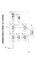
2.送信装置の構成
図2に、上記のトランスポートストリームを生成して送信するための送信装置の構成を示す。図においては、トランスポートストリームTS1についてのみ示したが、他のトランスポートストリームTS2、TS3も同じように生成される。
【0101】
サービスSV11の画像/音声データES11は、エンコーダE1によって圧縮されて多重化部10に与えられる。同様に、サービスSV12の画像/音声データES12はエンコーダE2によって圧縮されて多重化部10に与えられ、サービスSV13の画像/音声データES13はエンコーダE3によって圧縮されて多重化部10に与えられ、サービスSV14の画像/音声データES14はエンコーダE4によって圧縮されて多重化部10に与えられる。
【0102】
制御データ生成部16は、パケット多重化のための制御データ、番組情報を示すための制御データ、現在時刻を示す制御データ等を生成する。パケット多重化のための制御データは、時分割してパケット化された複数のサービスの画像/音声データを、正しく識別するなどのために付される。
【0103】
多重化部10は、制御データ、圧縮された画像/音声データES11、ES12、ES13、ES14を時分割して固定長のパケットにし、トランスポートストリームTS1として出力する。
【0104】
スクランブラ12は、出力されたパケットに対し、スクランブル鍵制御部16から与えられるスクランブル鍵を用いてスクランブルをかける。スクランブルのかけられたトランスポートストリームTS1は、変調部14において変調され、放送衛星4を介して視聴者に放送される。
【0105】
なお、スクランブラ12において用いられたスクランブル鍵は、ECM生成部8において暗号化され、ECM(Entitlement Control Message)データとされる。つまり、スクランブルを解くための鍵をさらに暗号化したECMデータを生成している。多重化部54は、このECMデータも含めてパケット化する。
【0106】
3.トランスポートストリームの構造
図2の送信装置によって生成されたトランスポートストリームTS1には、図3に示すように、サービスSV11の映像データES(V)1、音声データES(A)1、サービスSV12の映像データES(V)2、音声データES(A)2、サービスSV13の映像データES(V)3、音声データES(A)3、サービスSV14の映像データES(V)4、音声データES(A)4が多重化されている。
【0107】
さらに、パケット多重化のための制御データNIT、PAT、PMT1、PMT2、PMT3、PMT4も多重化されている。これら制御データにより、多重化された各サービスSV11、SV12、SV13、SV14の映像/音声データを分離することができる。
【0108】
また、スクランブル鍵のための制御データECM1、ECM2、ECM3、ECM4、番組情報を示す制御データEIT1、EIT2、EIT3、EIT4、現在日時を示す制御データTDTなども多重化されている。なお、図には示していないが、その他多くの制御データが多重化されている。
【0109】
パケット化は、図3の縦線18aに示すように行われる。つまり、制御データNIT、PAT、PMT、EIT、TDT、ECM、映像データES(V)、音声データES(A)の順にパケット化が行われる。音声データES(A)3までのパケット化が完了すれば、再び、制御データNIT以下のパケット化を繰り返す(縦線18b参照)。
【0110】
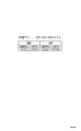
図4に、パケット化されたデータの基本的構造を示す。制御データ、映像/音声データともに、図4に示すようなデータ構造を持つパケットとされる。パケット化データの先頭には、パケットID(PID)が付される。パケットIDは、各パケットを識別するため各パケットごとにユニークに付された符号である。内容データは、パケット化された対象データ(制御データ、映像/音声データなど)である。
【0111】
図5に、パケット多重化のための制御データPMT1のデータ内容を示す。PMT1には、サービスSV11の映像データES(V)1、音声データES(A)1のパケットID、およびこれらのスクランブルを解くためのECM1のパケットIDが記述されている。PMT2、PMT3、PMT4には、それぞれ、サービスSV12、SV13、SV14に関して、同様のパケットIDが記述されている。
【0112】
図6に示すように、PATには、サービスSV11に対応するPMT1のパケットID、サービスSV12に対応するPMT2のパケットID、サービスSV13に対応するPMT3のパケットID、サービスSV14に対応するPMT4のパケットIDが記述されている。
【0113】
図7に示すように、NITには、全てのトランスポートストリームTS1、TS2、TS3について、その周波数、偏波面などの伝送諸元、および当該トランスポートストリームに多重化されているサービスのリストが記述されている。これにより、ある特定のサービスが、いずれの周波数のトランスポートストリームに多重化されているかを知ることができる。
【0114】
4.受信装置の構成
図8に、受信装置の概要を示す。チューナ22によって、トランスポートストリームが選択され、デ・スクランブラ24によってスクランブルが解除され、トランスポートデコーダ26によって所望のサービスに関する映像/音声データESが分離される。なお、マイクロプロセッサ(MPU)28は、取得したECMをICカード30に送り、ICカード30によって復元されたクランブル鍵を受け取る。MPU28は、このスクランブル鍵をデ・スクランブラ24に設定する。これにより、映像/音声データESのスクランブルを解くことができる。
【0115】
なお、MPU28は、所望のサービスの映像/音声データESのパケットIDをトランスポートデコーダ26にセットする。これにより、トランスポートデコーダ26は、当該サービスの映像/音声データESを出力する。また、制御データのパケットIDをトランスポートデコーダ26にセットした場合には、分離された制御データはMPU28に与えられる。
【0116】
現在、トランスポートストリームTS3のサービスSV33を受信しているとして、トランスポートストリームTS1のサービスSV12に切り換える旨の指令がMPU28に与えられた場合の動作を、以下説明する。まず、MPU28は、トランスポートデコーダを制御して(すなわち、制御データNITのパケットIDをセットして)、NITを取り込む。このNITの記述により、受信を希望するサービスSV12がトランスポートストリームTS1に多重化されていることを知る(図7参照)。
【0117】
次に、チューナ8を制御して、トランスポートストリームTS1を受信する。さらに、トランスポートデコーダ26を制御して、PATおよびPMT2を取得し、所望のサービスSV12の映像データES(V)2、音声データES(A)2のパケットIDおよびそのECMのパケットIDを得る。
【0118】
次に、これらパケットIDをトランスポートデコーダ26にセットして、所望のサービスSV12の映像データES(V)2、音声データES(A)2をトランスポートデコーダ26から出力させる。なお、これと並行して、MPU28は、トランスポートデコーダ26から得たECMをICカード30に送ってスクランブル鍵を取得し、デ・スクランブラ24に設定する。これにより、スクランブルの解除された映像データES(V)2、音声データES(A)2を得ることができる。上記のようにして、受信するサービスの切り換えが行われる。
【0119】
また、番組予定や番組情報を表示する旨の命令がMPU28に与えられると、MPU28は、トランスポートデコーダ26を制御してEITを取得する。さらに、取得したEITに基づいて、番組情報等を表示するように制御する。
【0120】
b)第1の実施形態
5.受信記録再生装置
5.1.受信記録再生装置の全体構成
図9に、この発明の一実施形態による受信記録再生装置32の全体構成を示す。アンテナ20によって捕捉された電波は、受信手段34によって1つのトランスポートストリームとして復調される。受信モードにおいては、受信手段34からのトランスポートストリームは復元手段40に与えられる。復元手段40は、このトランスポートストリームから、所望のサービスに関するパケットを選択して、当該パケットの内容にしたがって、サービス内容信号(たとえばNTSCのようなコンポジット信号)を復元して出力する。映像・画像出力手段46は、このサービス内容信号を受けて、映像、画像を出力する。
【0121】
記録モードにおいては、受信手段34からのトランスポートストリームは変換手段36に与えられる。変換手段36は、このトランスポートストリームを、記録に適した状態のパケット多重化ストリームに変換し、変換ストリームとして出力する。変換手段36は、トランスポートストリームから所望のサービスに関するパケットを選択するとともに、これらパケットのうち、再生時に必要となるパケットのみを選択して変換ストリームを生成する。記録手段38は、この変換ストリームを記録媒体44に記録する。
【0122】
再生モードにおいては、読出手段42によって、記録媒体44から変換ストリームが読み出される。読み出された変換ストリームは、復元手段40に与えられる。復元手段40は、この変換ストリームの内容にしたがって、サービス内容信号(たとえばNTSCのようなコンポジット信号)を復元して出力する。映像・画像出力手段46は、このサービス内容信号を受けて、映像、画像を出力する。
【0123】
この実施形態では、従来装置のように復元手段40からのサービス内容信号を記録するのではなく、パケットの状態のままで記録するようにしている。したがって、制御データを含めて記録することができるので、制御データに基づく衛星放送の機能を損なうことなく記録再生を行うことができる。また、映像・音声ともにディジタル的に圧縮された状態にて記録できるので、記録媒体の容量を有効に活用することができる。
【0124】
さらに、トランスポートストリームのうちから所望のサービスに関するパケットのみを選択して記録しているので、記録に必要な容量を小さくすることができる。加えて、当該パケットの中から、再生時に必要なパケットだけを選択して記録しているので、記録に必要な容量を小さくすることができる。
【0125】
5.2.受信記録再生装置の具体的構成例および動作
図10に、図9に示す受信記録再生装置32をCPUを用いて実現した場合のブロック図を示す。この受信記録再生装置32は、受信部68と記録再生部70を備えている。CPU58は、メモリ60に記録されたプログラムにしたがって各部の制御を行う。
【0126】
この装置は、受信モード、記録モード、再生モードの3つのモードを有している。以下では、それぞれのモードについて、その動作を説明する。
【0127】
(1)受信モード
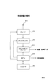
メモリ60に記録された受信モードのプログラムを、図11にフローチャートにて示す。
【0128】
現在、トランスポートストリームTS1のサービスSV13を受信しているとして、トランスポートストリームTS1のサービスSV11に切り換える旨の指令がCPU58に与えられた場合の動作を、以下説明する。なお、CPU58に対する指令は、操作パネルまたは操作リモコンから与えられる。図10に示す、操作入力部54は、この操作パネルまたは操作リモコンからの指令を受ける受光部である。
【0129】
まず、CPU58は、トランスポートデコーダ(TSデコーダ)50の制御データ分離用のレジスタ(図示せず)にPATのパケットIDをセットする。PATのパケットIDは、固定的に「0x00」と決められている。これにより、TSデコーダ50は、分離したPATの内容をメモり60に記録する(ステップS11)。このPATには、現在受信しているトランスポートストリームTS1に多重されているサービスの一覧が記述されている(図6参照)。したがって、CPU58は、希望されているサービスSV11が現在受信中のトランスポートストリームTS1に多重されていることを知る。つまり、CPU58は、ステップS12からS18に処理を進める。
【0130】
ステップS18においては、取得したPATに基づいて、所望のサービスSV11のPMTのパケットIDを取得する。ここでは、「0x11」が取得される(図6参照)。次に、CPU58は、PMTのパケットID「0x11」を、TSデコーダ50の制御データ分離用レジスタにセットする。これにより、サービスSV11のPMT1を分離して、その内容をメモリ60に取得することができる(ステップS19)。
【0131】
サービスSV11のPMT1を図5に示す。CPU58は、このPMT1に基づいて、映像および音声のデータのスクランブル鍵を得るためのECMデータのパケットID「0x21」を知ることができる。同様に、映像および音声データES(V)1、ES(A)1のパケットID「0x22」「0x24」を知ることができる(ステップS20)。
【0132】
CPU58は、ECMのパケットID「0x21」をTSデコーダ50の制御データ分離用レジスタにセットして、ECMを取得する。さらに、このECMをICカード56に与え、復元されたスクランブル鍵を取得する。このようにして取得したスクランブル鍵を、デ・スクランブラ48に設定する(ステップS21)。これにより、サービスSV11の映像データES(V)1、音声データES(A)1のパケットは、スクランブルが解除された状態となる。
【0133】
また、CPU58は、映像および音声データES(V)1、ES(A)1のパケットID「0x22」「0x24」を、TSデコーダ50のES分離用レジスタ(図示せず)にセットする(ステップS22)。これにより、TSデコーダ50は、分離した映像および音声データES(V)1、ES(A)1を、AVデコーダ52に出力する。
【0134】
これを受けたAVデコーダは、圧縮を伸張(解凍)し、D/A変換を行ってビデオ・コンポジット信号を生成する。この信号は、TVセット46に与えられ、映像・音声として出力される。
【0135】
上記のようにして受信モードにおける処理が行われる。なお、ステップS12において、現在受信中のトランスポートストリームに希望するサービスが多重されていない場合には、ステップS13に進む。ステップS13においては、PATに記述されているNITのパケットIDを取得する。これに基づいて、NITを取得し、所望のサービスがいずれのトランスポートストリームに多重されているかを知る(ステップS14、S15)。
【0136】
CPU58は、当該トランスポートストリームを受信するようにチューナー34の設定を切り換える(ステップS16)。その後、当該トランスポートストリームのPATを取得する(ステップS17)。以後は、上記のステップS18以下を実行すればよい。
【0137】
(2)記録モード
図12に、メモリ60に記録された記録モードのプログラムを、フローチャートにて示す。ステップS11〜S22は、受信モードと同じである。したがって、図12においては、ステップS23以降についてのみ示している。操作入力部54から、記録命令が与えられると記録モードとなる。
【0138】
まず、ステップS23において、CPU58は、TSデコーダの記録データ分離用レジスタ(図示せず)に、所望のサービスSV11の映像および音声データES(V)1、ES(A)1のパケットID、NITのパケットID、PATのパケットID、所望のサービスSV11のPMT1のパケットIDをセットする。これにより、TSデコーダ50は、映像および音声データES(V)1、ES(A)1、PAT、PMT1、NITを、パケット状態のままで、記録再生部70の変換ストリーム生成部62に出力する。
【0139】
CPU58は、メモリ60に記録したPMT1を取得し、記述されている情報のうち、所望のサービスSV11に関する情報のみを選択し、変換PMT1を生成する(ステップS24)。たとえば、PMT1に含まれる情報のうち、ECMのパケットIDは再生時に不要であるため取り除かれる。これにより、PMT1に含まれている情報のうち、所望のサービスSV11の記録再生のために関係しない情報が取り除かれた変換PMT1が得られる。
【0140】
次に、CPU58は、記録される変換ストリームに含まれるサービスおよびイベント(番組)の情報を記述した制御データSITを生成する(ステップS25)。
【0141】
CPU58は、上記のようにして生成した変換PMT1、SITをMPU64に与える。MPU64は、これを変換ストリーム生成部62に与え、変換ストリームを生成させる。
【0142】
変換ストリーム生成部62は、TSデコーダ50からのPATを受けて、所望のサービスSV11に関する情報のみを含む変換PATを生成し、PATを変換PATで置き換える。この際、PATに含まれていたNITのパケットIDは、SITのパケットIDに変える。また、TSデコーダ50からのPMTを、MPU64から受けた変換PMTに置き換える。さらに、TSデコーダ50からのNITを、MPU64から受けたSITに置き換える。
【0143】
このようにして、所望のサービスのES、SIT、変換PAT、変換PMTのパケット多重化された変換ストリームが得られる。
【0144】
CPU58は、記録命令をMPU64に与える(ステップS27)。これを受けて、MPU64は、記録・読出部66を制御して、磁気テープ44に変換ストリームを記録する。記録される変換ストリームを模式化して示すと、図13のようになる。
【0145】
操作入力部54から記録停止命令が与えられると、CPU58は、これをMPU64に与える(ステップS28、S29)。MPU64は、これを受けて、記録・読出部66による記録を停止する。
【0146】
なお、磁気テープ44に記録される変換ストリームには、同じ内容の制御データであっても、何回もパケット多重化されて記録されている。したがって、磁気テープの途中からであっても、再生を行うことができる。
【0147】
また、記録中に、サービスの選択が変更されると、途中から変更されたサービスが記録されることとなる。この際、変換ストリーム生成部62は、情報が不連続になったことを自らが検出して(またはCPU58からの指令に基づいて)、情報の不連続点を示す制御データDIT(Discontinuity Information Table)を生成する。さらに、このDITを、図14に示すように、変更されたサービスの先頭にパケット多重化する。同様に、新たな記録を行う場合には、先頭にこのDITが付される。また、同一サービス内の異なる番組を連続して記録した場合にもDITが付される。
【0148】
上記においては、記録再生装置70に変換ストリーム生成部62を設けているが、受信装置68にこれを設けるようにしてもよい。この場合、記録再生装置70は、受信装置68から出力される変換ストリームをそのまま記録することとなる。
【0149】
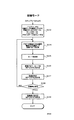
(3)再生モード
図15に、メモリ60に記録された再生モードのプログラムを、フローチャートにて示す。操作入力部54から、再生命令が与えられると再生モードとなる。
【0150】
まず、CPU58は、ステップS31において、再生命令をMPU64に与える。MPU64は、これを受けて、記録読出部66を制御し、磁気テープ44から変換ストリームを読み出させる。読み出された変換ストリームは、TSデコータ50に与えられる。
【0151】
次に、TSデコーダ50の制御データ分離用レジスタに、変換PATのパケットID「0x00」をセットして、変換ストリーム中から変換PATを分離し、メモリ60に記憶する(ステップS32)。この変換PATの記述に基づいて、変換PMTのパケットIDを認識する(ステップS33)。
【0152】
さらに、TSデコーダ50の制御データ分離用レジスタに、変換PMTのパケットIDをセットして、変換ストリーム中から変換PMTを分離し、メモリ60に記憶する(ステップS34)。この変換PMTの記述に基づいて、映像データES(V)、音声データES(A)のパケットIDを認識する(ステップS35)。
【0153】
次に、CPU58は、TSデコーダ50のES分離用レジスタに、映像データES(V)、音声データES(A)のパケットIDをセットして、変換ストリーム中からこれらを分離する。分離された映像データES(V)、音声データES(A)は、AVデコーダ52に出力される。
【0154】
これを受けたAVデコーダは、圧縮を伸張(解凍)し、D/A変換を行ってビデオ・コンポジット信号を生成する。この信号は、TVセット46に与えられ、映像・音声として出力される。
【0155】
再生中に、変換ストリーム中のDITの存在を見いだすと、CPU58は、ステップS32に戻って、変換PATの以下の処理を行う(ステップS37)。DITは、記録されたデータの不連続点を示すからである。
【0156】
操作入力部54より再生停止命令があると、CPU58は、これをMPU64に与える(ステップS38、S39)。これを受けて、MPU64は、記録・読出部66を制御して、磁気テープ44からの読み出しを停止する。
【0157】
5.3.他の実施形態
図10の実施形態では、TSデコーダ50、変換ストリーム生成部62およびCPU58(特に、ステップS24、S25)によって、変換手段36を実現している。また、TSデコーダ50およびCPU58(特に、ステップS32〜S36)によって、復元手段40を実現している。このように、TSデコーダ50を、変換手段、復元手段の双方に共用しているので、構成を簡易にすることができる。
【0158】
図10の実施形態では、CPU58が変換ストリーム生成の一部分を実行している(ステップS24、S25)が、これらの処理も、変換ストリーム生成部62が行ってもよい。さらに、TSデコーダ50において選択されたパケットのみが変換ストリーム生成部62に与えられているが、デ・スクランブラ48からのトランスポートストリームをそのまま変換ストリーム生成部62に与えるようにしてもよい。この場合、変換ストリーム生成部62が、必要なパケットの選択を行う。
【0159】
なお、図10では、受信記録再生装置32として示したが、受信部68だけで構成される受信装置としてもよい。この場合には、TSデコーダの出力50aを取り出すための記録用データ出力端子、記録再生部70からの変換ストリーム50bを受けるための復元用データ入力端子を設けるとよい。
【0160】
また、記録再生部70だけで構成される記録再生装置としてもよい。さらに、記録再生部70の再生機能だけで構成される再生装置、記録再生部70の記録機能だけで構成される記録装置としてもよい。
【0161】
また、上記実施形態では、デ・スクランブルされたデータを記録するようにしているが、スクランブルされた状態のデータを記録するようにしてもよい。この場合には、ECMデータも併せて記録しておく。この場合、ECMデータをそのまま記録してもよいし、SITデータの一部として記録してもよい。
【0162】
c)第2の実施形態
6.受信記録再生装置
6.1.受信記録再生装置の全体構成
図16に、第2の実施形態による受信記録再生装置の全体構成を示す。この実施形態では、変換ストリームを作成する際の環境(つまり記録の際の環境)を取得する記録環境取得手段72が設けられており、変換手段36は、この記録環境を含んだ変換ストリームを生成する。したがって、記録媒体44には、記録環境を含んだ変換ストリームが記録される。
【0163】
再生環境取得手段74は、再生の際の環境を取得する。復元手段40は、再生環境取得手段74からの再生環境と、記録媒体から読み出した記録環境とを比較し、両環境の違いに基づいて再生制御の内容を変える。
【0164】
したがって、記録環境と再生環境との違いに基づいて、適切な再生を行うことができる。
【0165】
6.2.受信記録再生装置の具体的構成例および動作
図16に示す受信記録再生装置32をCPUを用いて実現した場合のブロック図は、図10と同様である。
【0166】
この装置は、受信モード、記録モード、再生モードの3つのモードを有している。受信モードは、第1の実施形態と同様であるから、記録モード、再生モードについて、その動作を説明する。
【0167】
(1)記録モード
図17に、メモリ60に記録された記録モードのプログラムをフローチャートにて示す。基本的な処理は、図12と同じである。ステップS231において、CPU58は、メモリ60に記録されたこの装置自身のIDを取得する。さらに、CPU58は、SIT生成の際に、この装置IDをSITの記述中(たとえば、descriptor領域)に含める(ステップS25)。したがって、磁気テープ44に記録される変換ストリームには、記録環境としての装置IDが含まれることになる。
【0168】
(2)再生モード
図18に、メモリ60に記録された再生モードのプログラムをフローチャートにて示す。基本的な処理は、図15と同じである。CPU58は、ステップS321において、変換PATに基づいて、SITのパケットIDを取得する。これをTSデコーダ50の制御データ分離用レジスタにセットし、SITを取得する(ステップS322)。続いて、CPU58は、取得したSITに記述されている装置IDを取得する(ステップS323)。また、メモリ60に記録されているこの装置自身のIDを読み出す(ステップS324)。
【0169】
さらに、これら装置IDが合致するか否かを判断する(ステップS325)。合致する場合(つまり、磁気テープ44に記録した装置と再生している装置が同じ場合)には、ステップS33以下を実行し、再生を行う。合致しない場合(つまり、磁気テープ44に記録した装置と再生している装置が異なる場合)には、その旨の表示をして(ステップS326)、再生を終了する。
【0170】
この実施形態によれば、ペイパービューなどの有料放送を記録したテープを、本人以外の装置にて再生することを禁止することができる。
【0171】
なお、上記実施形態では、IDが合致しない場合に再生を行わないようにしたが、再生内容を変えて再生を行うようにしてもよい。
【0172】
6.3.記録環境と再生環境
上記実施形態では、記録および再生環境として装置IDを用いている。しかし、ICカードのIDを用いてもよい。また、装置の種類を記録環境として記録し、再生の際に用いた装置の種類と比較して、その違いに基づいて、記録データフォーマット等を変換して再生するようにしてもよい。
【0173】
なお、上記実施形態では、記録に用いた装置、再生に用いた装置を、記録環境、再生環境としている。しかし、記録時、再生時を、記録環境、再生環境としてもよい。また、記録場所、再生場所を、記録環境、再生環境としてもよい。
【0174】
また、上記実施形態では、SITに記録環境を記記述するようにしたが、変換PAT、変換PMT等に記述するようにしてもよい。
【0175】
7.その他の実施形態
上記の実施形態では、送信装置から送るトランスポートストリームは、第1の実施形態と同じものである。しかし、記録環境と再生環境のずれの程度と、これに対応して処理すべき内容とを示すデータを、送信装置からトランスポートストリームに含ませて送信するようにし、受信側の記録再生装置では、このデータにしたがって、記録環境と再生環境のずれに基づいて処理内容を変えるようにしてもよい。
【0176】
d)第3の実施形態
8.受信記録再生装置
8.1.受信記録再生装置の全体構成
図19に、第3の実施形態による受信記録再生装置の全体構成を示す。この実施形態では、再生の際の環境を取得する再生環境取得手段74が設けられている。復元手段40は、再生モードでは、再生環境取得手段74からの再生環境を考慮して、当該環境に応じた適切な再生内容を出力する。
【0177】
8.2.受信記録再生装置の具体的構成例および動作
図19に示す受信記録再生装置32をCPUを用いて実現した場合のブロック図は、図10と同様である。
【0178】
この装置は、受信モード、記録モード、再生モードの3つのモードを有している。以下、受信モード、記録モード、再生モードについてその動作を説明する。
【0179】
(1)受信モード
この実施形態では、2カ国語(たとえば英語と日本語)放送を受信する場合を例として説明する。2カ国語放送の場合、図20に示すように、音声データとして、ES(A)1JとES(A)1Eの2つのストリームが多重化されている。音声データES(A)1Jは日本語の音声であり、音声データES(A)1Eは英語の音声である。
【0180】
図21に、メモリ60に記録された受信モードのプログラムをフローチャートにて示す。基本的な処理は、図11と同じである。ステップS121において、CPU58は、TSデコーダ50の制御データ分離用レジスタにSDTのPIDをセットして、SDTを取得する。SDT(Service Description Table)には、このトランスポートストリームに多重化されている各サービスについてその詳細が記述されている。また、SDTには、2カ国語放送の場合、各言語のストリームが何れのパケットIDに対応しているか、さらに、デフォルトとして何れの言語を選択するかも記述されている。CPU58は、このデフォルトの音声のパケットIDを取得する。ここでは、ES(A)1JのパケットIDが記述されており、これを取得したものとする。
【0181】
CPU58は、ステップS20において、ES(V)1のパケットIDとES(A)1JのパケットIDとを、TSデコーダ50にセットする。これにより、日本語音声によるサービスが出力される。
【0182】
操作者は、操作入力部54に音声切換命令を与えることにより、CPU58の制御によって、ES(A)1Eを分離して、英語音声によるサービスに切り換えることができる。
【0183】
(2)記録モード
図22に、メモリ60に記録された記録モードのプログラムをフローチャートにて示す。基本的な処理内容は、図12と同様である。ただし、ステップS23において、日本語音声のES(A)および英語音声のES(A)の双方のパケットIDをセットして、記録再生部70に出力するようにしている。したがって、磁気テープ44には、日本語音声のES(A)および英語音声のES(A)の双方が記録されることになる。CPU58は、ステップS25において、SDTに記述された日本語のES(A)のパケットIDおよび英語のES(A)のパケットIDを、SITの記述に含めるようにする。
(3)再生モード
図23に、メモリ60に記録された再生モードのプログラムをフローチャートにて示す。基本的な処理内容は、図15と同様である。
【0184】
CPU58は、ステップS321、S322、S327において、日本語音声のES(A)のパケットIDと、英語音声のES(A)のパケットIDを取得し、メモリ60に一時記憶する。次に、CPU58は、メモリ60に予め記録された設置場所情報を読み出す(ステップS328)。ここでは、再生を行った装置の設置場所が米国であったとする。
【0185】
次に、CPU58は、メモリ60に記録された設置場所と言語との対応表(図示せず)に基づいて、適切な言語を選択する。ここでは、英語が選択され、英語音声のES(A)のパケットIDがデフォルトとして選択される。
【0186】
CPU58は、ステップS36において、この英語音声のES(A)のパケットIDをTSデコーダ50にセットする。これにより、デフォルトの状態において英語音声によるサービスが出力される。
【0187】
操作者は、操作入力部54に音声切換命令を与えることにより、CPU58の制御によって、日本語音声のES(A)を分離して、日本語音声によるサービスに切り換えることができる。
8.3.その他の再生環境等
上記の実施形態においては、再生装置の設置場所に基づいて、再生内容を変えるようにしている。しかし、再生時や再生装置(装置IDや装置の種類)等の再生環境に基づいて、再生内容を変えるようにしてもよい。
【0188】
また、上記実施形態では、再生環境取得手段74を設け、再生環境に応じた再生内容を実現している。しかしながら、再生環境取得手段74を設けることなく、再生モードであるということに基づいて、受信モードとは異なる再生内容を出力するようにしてもよい。
【0189】
9.その他の実施形態
上記の実施形態では、再生環境とこれに対応して処理すべき内容とを示すデータは、受信記録再生装置のメモリ60に予め記録されている。しかしながら、このデータを、送信装置からトランスポートストリームに含ませて送信するようにし、受信側の記録再生装置では、このデータにしたがって、再生環境に対応して処理内容を変えるようにしてもよい。
【0190】
e)第4の実施形態
10.インタラクティブ性を有する衛星放送システムの概要
第4の実施形態を説明する前に、インタラクティブ性を有する放送システムの概要を説明する。
【0191】
送信装置の構成は図2と同様である。ただし、制御データ生成部6が、後述するナビゲーションデータも生成する点が異なる。
【0192】
図24に、インタラクティブ性を有する放送システムにおいて、送信装置から送られてくるトランスポートストリームのデータ構造を示す。図においては、サービスSV11の映像ES(V)11、ES(V)12、音声ES(A)11、ES(A)12を示し、他のサービスの映像、音声のエレメンタリーストリームについては省略している。図3のデータ構造と異なる点は、1つのサービスSV11に、2つの映像/音声のESが含まれている点である。この2つの映像/音声のESを、インタラクティブ制御データであるナビゲーションデータNVT1、NVT2に基づいて、受信側の操作者の操作に応じて、インタラクティブに切り換えることができるようにしている。また、ナビゲーションデータNVT1、NVT2に基づいて、受信側の操作者の操作に応じて、インタラクティブに付加的な表示を変更できるようにしている。
【0193】
図25に、サービスSV11のPMT1の内容を示す。制御データPMT1には、各コンテンツ(映像、音声、ナビゲーションデータ)のパケットID、当該コンテンツのスクランブルを解く鍵を得るためのECMデータのパケットIDが記述されている。さらに、映像、音声、ナビゲーションデータともに複数のコンテンツがあるので、最初に出力すべきものを、エントリコンテンツとして記述している。この制御データPMT1自身のパケットIDは「0x0011」である。
【0194】
図26に、制御データPATの内容を示す。制御データPATには、このトランスポートストリームTS1に多重化されているサービスSV11、SV12、SV13、SV14に関するPMTのパケットIDが記述されている。これにより、サービスSV11のパケットIDが「0x0011」であることを知ることができる。なお、この制御データPAT自身のパケットIDは、固定的に「0x0000」と定められている。
【0195】
図27、図28に、ナビゲーションデータNVT1、NVT2に記述されている内容を示す。この1組のナビゲーションデータNVT1、NVT2は、所定期間にわたって、同じ内容のものが、繰り返し送られている。ナビゲーションデータNVT1、NVT2によって、操作者の操作に応じインタラクティブに、サービスの内容を図29〜図32に示すように変更することを実現している。その詳細については、後述する。
【0196】
11.受信記録再生装置
11.1.受信記録再生装置の全体構成
図33に、この実施形態による受信記録再生装置32の全体構成図を示す。アンテナ20によって捕捉された電波は、受信手段34によって1つのトランスポートストリームとして復調される。受信モードにおいては、受信手段34からのトランスポートストリームは復元手段40に与えられる。復元手段40は、このトランスポートストリームから、所望のサービスに関するパケットを選択して、当該パケットの内容にしたがって、サービス内容信号(たとえばNTSCのようなコンポジット信号)を復元して出力する。映像・画像出力手段46は、このサービス内容信号を受けて、映像、画像を出力する。
【0197】
また、復元手段40は、操作受付手段54からの操作入力に基づいて、ナビゲーションデータにしたがって、出力するサービス信号の内容をインタラクティブに変更する。
【0198】
記録モードにおいては、受信手段34からのトランスポートストリームは変換手段36に与えられる。変換手段36は、このトランスポートストリームを、記録に適した状態のパケット多重化ストリームに変換し、変換ストリームとして出力する。変換手段36は、トランスポートストリームから所望のサービスに関するパケットを選択するとともに、これらパケットのうち、再生時に必要となるパケットのみを選択して変換ストリームを生成する。所望のサービスがナビゲーションデータを含むものである場合には、変換手段36は、ナビゲーションデータを含んだ変換ストリームを生成する。記録手段38は、この変換ストリームを記録媒体44に記録する。
【0199】
再生モードにおいては、読出手段42によって、記録媒体44から変換ストリームが読み出される。読み出された変換ストリームは、復元手段40に与えられる。復元手段40は、この変換ストリームの内容にしたがって、サービス内容信号(たとえばNTSCのようなコンポジット信号)を復元して出力する。映像・画像出力手段46は、このサービス内容信号を受けて、映像、画像を出力する。
【0200】
また、復元手段40は、操作受付手段54からの操作入力に基づいて、ナビゲーションデータにしたがって、出力するサービス信号の内容をインタラクティブに変更する。
【0201】
この実施形態では、従来装置のように復元手段40からのサービス内容信号を記録するのではなく、パケットの状態のままで記録するようにしている。したがって、制御データを含めて記録することができるので、制御データに基づく衛星放送の機能を損なうことなく記録再生を行うことができる。特に、ナビゲーションデータも併せて記録するので、再生時においても、インタラクティブ性のあるサービスを再現することができる。
【0202】
従来装置のように、ビデオコンポジット信号にて記録する方式であれば、インタラクティブ性のあるサービスであっても、記録時における操作入力にしたがった固定的な内容しか記録することができない。しかし、この実施形態によれば、インタラクティブ性を保持しつつ記録を行うことができる。
【0203】
また、映像・音声ともにディジタル的に圧縮された状態にて記録できるので、記録媒体の容量を有効に活用することができる。さらに、トランスポートストリームのうちから所望のサービスに関するパケットのみを選択して記録しているので、記録に必要な容量を小さくすることができる。加えて、当該パケットの中から、再生時に必要なパケットだけを選択して記録しているので、記録に必要な容量を小さくすることができる。
【0204】
11.2.受信記録再生装置の具体的構成例および動作
図34に、図33に示す受信記録再生装置32をCPUを用いて実現した場合のブロック図を示す。この受信記録再生装置32は、受信部68と記録再生部70を備えている。CPU58は、メモリ60に記録されたプログラムにしたがって各部の制御を行う。
【0205】
この装置は、受信モード、記録モード、再生モードの3つのモードを有している。以下では、それぞれのモードについて、その動作を説明する。
【0206】
(1)受信モード
ここでは、図24に示すようなトランスポートストリームが送られてきているものとする。また、サービスSV11には、映像データES(V)11、ES(V)12、音声データES(A)11、ES(A)12が含まれており、映像データES(V)11、音声データES(A)11は日用品に関するテレビショッピングの内容、映像データES(V)12、音声データES(A)12は衣料品に関するテレビショッピングの内容であるものとする。
【0207】
メモリ60に記録された受信モードのプログラムを、図36にフローチャートにて示す。
【0208】
現在、トランスポートストリームTS1のサービスSV13を受信しているとして、トランスポートストリームTS1のサービスSV11に切り換える旨の指令がCPU58に与えられた場合の動作を、以下説明する。なお、CPU58に対する指令は、操作パネルまたは操作リモコンから与えられる。図34に示す操作入力部54は、この操作パネルまたは操作リモコンからの指令を受ける受光部である。
【0209】
まず、CPU58は、トランスポートデコーダ(TSデコーダ)50の制御データ分離用のレジスタ(図示せず)にPATのパケットIDをセットする。PATのパケットIDは、固定的に「0x0000」と決められている。これにより、TSデコーダ50は、分離したPATの内容をメモり60に記録する(ステップS11)。このPATには、現在受信しているトランスポートストリームTS1に多重されているサービスの一覧が記述されている(図26参照)。したがって、CPU58は、希望されているサービスSV11が現在受信中のトランスポートストリームTS1に多重されていることを知る。つまり、CPU58は、ステップS12からS18に処理を進める。
【0210】
ステップS18においては、取得したPATに基づいて、所望のサービスSV11のPMTのパケットIDを取得する。ここでは、「0x0011」が取得される(図26参照)。次に、CPU58は、PMTのパケットID「0x0011」を、TSデコーダ50の制御データ分離用レジスタにセットする。これにより、サービスSV11のPMT1を分離して、その内容をメモリ60に取得することができる(ステップS19)。
【0211】
サービスSV11のPMT1を図25に示す。CPU58は、このPMT1に基づいて、サービスSV11にナビゲーションデータNVTを含むかどうか(つまり、インタラクティブ性のあるサービスであるかどうか)を判断する(ステップS191)。NVTを含まない場合には、図11の場合と同様の処理が行われて、当該サービスの内容がTVセット46から出力される(ステップS20、S21、S22)。
【0212】
図25に示すようにNVTを含む場合には、CPU58は、PMT1の内容から、エントリコンテンツである映像、音声、ナビゲーションデータのパケットIDと、そのECMのパケットIDを認識する(ステップS192)。ここでは、映像データES(V)11のパケットID「0x0096」、音声データES(A)11のパケットID「0x0098」、ナビゲーションデータNVT1のパケットID「0x0092」およびこれらのECMデータのパケットID「0x0082」を認識する。
【0213】
次に、CPU58は、ECMのパケットID「0x0082」をTSデコーダ50の制御データ分離用レジスタにセットして、ECMデータを取得する。さらに、このECMデータをICカード56に与え、ICカード56によって復元されたスクランブル鍵を取得する。このようにして取得したスクランブル鍵を、デ・スクランブラ48に設定する(ステップS193)。これにより、サービスSV11の映像データES(V)11、ES(V)12、音声データES(A)11、ES(A)12、ナビゲーションデータNVT1、NVT2のパケットは、スクランブルが解除された状態となる。
【0214】
また、CPU58は、映像および音声データES(V)11、ES(A)11のパケットID「0x0096」「0x0098」を、TSデコーダ50のES分離用レジスタ(図示せず)にセットする(ステップS194)。これにより、TSデコーダ50は、分離した映像および音声データES(V)11、ES(A)11を、AVデコーダ52に出力する。
【0215】
これを受けたAVデコーダは、圧縮を伸張(解凍)し、D/A変換を行ってビデオ・コンポジット信号を生成する。この信号は、TVセット46に与えられ、映像・音声として出力される。ここでは、図29に示すような、日用品のテレビショッピングの動画が表示されたものとする。なお、画面右下のボタンB0、B1、B2は、以下のナビゲーションデータによって表示されるものであり、映像および音声データES(V)11、ES(A)11には含まれていない。
【0216】
また、CPU58は、上記ステップS194において、ナビゲーションデータNVT1のパケットID「0x0092」を、TSデコーダ50の制御データ分離用レジスタ(図示せず)にセットする。これにより、ナビゲーションデータNVT1が、メモリ60に一時的に記録される。ここでは、図27に示すようなナビゲーションデータNVT1が取り込まれたものとする。
【0217】
続いて、このようにして記録されたナビゲーションデータを解釈して実行する(ステップS195)。
【0218】
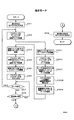
図37に、メモリ60に記録されたナビゲーションデータを解釈して実行するするプログラムのフローチャートを示す。
【0219】
まず、図27のナビゲーションデータNVT1のオブジェクト表から、オブジェクト・インデックス番号「0」のものを読み出し、ここに示された情報に基づいて、画面上にボタンを表示する(ステップS1001)。つまり、X座標「500」、Y座標「200」の位置に、ビットマップ表に示されるビットマップデータを表示する。インデックス番号「0」のオブジェクトに対しては、フォーカス状態のビットマップを表示するように予め定められている。したがって、ここでは、ビットマップ・インデックス番号「1」のデータ(「大阪センターに申し込み」のハイライト表示)を表示するように制御される。
【0220】
具体的には,CPU58は、ビットマップ・インデックス番号「1」のデータ(「大阪センターに申し込み」のハイライト表示)を、AVデコーダ52の映像合成部52cに与える。これにより、映像合成部52cは、映像データES(V)11の上に、「大阪センターに申し込み」のハイライト表示を重ねた画像データを生成する。したがって、TVセット46においては、図29に示すように、ボタンB0が表示される。
【0221】
同様にして、図27のナビゲーションデータNVT1のオブジェクト表のインデックス「1」の情報に基づいて、図29のボタンB1が表示される。ただし、オブジェクト・インデックス「0」以外のものについては、ノーマル状態のビットマップ・インデックスのデータが表示される。つまり、ここでは、ハイライト表示されない「東京センターに申し込み」の表示処理がなされる(ステップS1002)。
【0222】
さらに、同じようにして、オブジェクト表のインデックス「2」の情報に基づいて、図29のボタンB2「衣料品ショップへ」(非ハイライト表示)の表示処理がなされる(ステップS1002)。
【0223】
以上のようにして、図29に示すように、商品説明の動画に対して、ボタンB0、B1、B2が重ねられた表示が得られる。画面から明らかなように、ボタンB0「大阪センターに申し込み」が選択された状態として表示されている。これに対応して、CPU58は、オブジェクト・インデックス「0」が、現在選択されているオブジェクトである旨を記憶している。
【0224】
次に、図38に示すリモコン78(または本体の操作パネル)から、カーソルを下へ移動させるキー82が押されると、操作入力部54はこれを受けて、CPU58に通知する。CPU58は、操作入力が何であるかを判断し(ステップS1003)、「カーソルを下へ移動させるキー」であればステップS1004に進む。
【0225】
ステップS1004においては、ナビゲーションデータNVT1のオブジェクト表にしたがい、現在選択されているオブジェクトの番号をインクリメントし、オブジェクト・インデックス「1」を選択状態とする。つまり、オブジェクト・インデックス「1」については、フォーカス状態の欄に示されるビットマップを表示し、それ以外のオブジェクト・インデックス「0」「2」については、ノーマル状態の欄に示されるビットマップを表示する。
【0226】
これにより、TVセット46の画面は、図30に示すように変化する。つまり、ボタンB1「東京センターに申込」が選択された状態となる。
【0227】
さらに、操作者がカーソルを下へ移動させるキー82が押されると、画面表示は図31に示すように、ボタンB2「衣料品ショップへ」が選択された状態となる。また、図31の状態からカーソルを上へ移動させるキー80が押されると、画面表示は図30に示す状態に戻る。
【0228】
なお、上記実施形態では、上下のカーソルキー80、82についての操作だけを示したが、オブジェクト・インデックスを二次元配列にしておけば、左右のキー86、88も考慮した操作を行うことができる。
【0229】
図31の状態において、リモコン78の決定ボタン84が押されると、CPU58は、ステップS1003からS1005に進む。ステップS1005において、CPU58は、ナビゲーションデータNVT1を参照し、現在選択状態であるオブジェクト・インデックスのハンドラ欄に記述されたハンドラ・インデックスを取得する。ここでは、オブジェクト・インデックス「2」が選択されているので、そのハンドラ欄のハンドラ・インデックス「2」を取得する。
【0230】
さらに、ハンドラ定義表を参照して、ハンドラ・インデックス「2」に対応するスクリプトを取り出して実行する(ステップS1006)。ここでは、「go to contents (index 1)」を取得する。go to contents( )は、ハイパーリンク表に示される( )内のインデックス番号を持つコンテンツに切り換える命令である。したがって、ハイパーリンク表に示されたハイパーリンク・インデックス「1」のコンテンツ(衣料品のテレビショッピング)への切り換えが行われる。
【0231】
ハイパーリンク表のハイパーリンク・インデックス「1」には、リンク先である映像、音声、ナビゲーションデータそれぞれのパケットID「0x0097」「0x0099」「0x0093」が記述されている。CPU58は、TSデコーダ50の、ES分離用レジスタにパケットID「0x0097」「0x0099」をセットし、制御データ分離用レジスタにパケットID「0x0093」をセットする。
【0232】
これにより、TSデコーダ50からAVデコーダに対して映像データES(V)12、音声データES(A)12が出力される。よって、TVセット46は、図32に示すような衣料品のテレビショッピングの動画を表示し、その音声を出力する。
【0233】
また、図28に示すナビゲーションデータNVT2が、TSデコーダ50によって分離され、ナビゲーションデータNVT1に代えて、メモリ60に記録される。このナビゲーションデータNVT2について、図37に示す処理が行われ、図32に示すように、ボタンB10、B11、B12が表示される。
【0234】
図32のように「大阪センターに申込」のボタンB10が選択されている状態で、操作者が決定ボタン84(図38参照)を押すと、画面に表示されている商品の購入申込を行うことができる。以下、その処理を説明する。
【0235】
決定ボタン84が押されると、CPU58は、ステップS1003からステップS1005に処理を進める。ステップS1005においては、ナビゲーションデータNVT2(図28参照)のオブジェクト表にしたがって、現在選択状態となっているインデックスのハンドラ欄から、ハンドラ・インデックスを取得する。ここでは、オブジェクト・インデックス「0」が選択状態となっているので、ハンドラ・インデックス「0」が取得される。
【0236】
次に、CPU58は、ハンドラ定義表のハンドラ・インデックス「0」に対応するスクリプトを実行する。つまり、send_string(index1,index2)が実行される。send_string(A,B)は、文字列表のインデックス「A」の電話番号に電話をして、インデックス「B」の文字列を送信する命令である。したがって、ここでは、CPU58は、文字列表の文字列インデックス「0」に対応する「06−6368−XXXX」を取得し、図34に示す回線通信部76を制御して、「06−6368−XXXX」に電話をかける。この電話番号は、このテレビショッピングの大阪受付センターの電話番号である。回線がつながると、CPU58は、文字列表の文字列インデックス「2」に対応する「商品コード:B−133」を送信する。この際、CPU58は、商品購入者を特定するためのIDを、ICカード56またはメモリ60から取得し、併せてこれも送信する。
【0237】
CPU58は、上記の通信がうまくいったかどうかを、メモリ60にオンラインログとして記録する。図39に、その記録例を示す。通信が成功した場合は「○」、不成功の場合は「X」が記録される。なお、CPU58は、通信を行った日時を、トランスポートストリームに含まれている制御データTDTや自身が内蔵するカレンダー、時計等から取得して記録する。
【0238】
このログを表示することにより、商品の購入申込が正しく行われたか否かを知ることができる。
【0239】
上記のようにして、受信モードにおける処理が実行される。なお、上記では説明しなかったが、この実施形態では、映像データにて説明される商品が時間とともに変わっていくようになっている。したがって、これに対応して内容の異なったナビゲーションデータ(たとえば、文字列表のインデックス「2」の商品コードの異なるもの)を送信するようにしている。
【0240】
(2)記録モード
図40に、メモリ60に記録された記録モードのプログラムを、フローチャートにて示す。ステップS11〜S22、S192〜S195は、受信モードと同じである。ナビゲーションデータを含まないサービスを記録する場合の処理、つまり、ステップS22に続く処理は、図12に示したとおりである。ここでは、ナビゲーションデータを含んだサービスを記録する場合の処理、つまり、ステップS195と並行して行われる記録処理を図40に示す。図40では、受信モードにおいて取得した情報(パケットID)を利用して処理を進めている。しかし、記録モードを受信モードとは別に独立して実行する場合には、受信モードと同様の処理により、所望のサービスのPID、制御データのPID等を取得する必要がある。
【0241】
CPU58は、ステップS23において、記録したいサービスのESのパケットID、ナビゲーションデータNVTのパケットID、NITのパケットID、PATのパケットID、PMTのパケットIDを、TSデコーダ50の記録データ分離用レジスタ(図示せず)にセットする。サービスSV11を記録する場合であれば、図25、図26、図7に示されるそれぞれのパケットIDをセットする。なお、映像データ、音声データ、ナビゲーションデータについては、日用品のテレビショッピング、衣料品のテレビショッピングの双方のパケットIDをセットする。
【0242】
これにより、TSデコーダ50は、映像および音声データES(V)11、ES(V)12、ES(A)11、ES(A)12、PAT、PMT1、NITを、パケット状態のままで、記録再生部70の変換ストリーム生成部62に出力する。
【0243】
CPU58は、メモリ60に記録したPMT1を取得し、記述されている情報のうち、所望のサービスSV11に関する情報のみを選択し、変換PMT1を生成する(ステップS24)。たとえば、PMT1に含まれる情報のうち、ECMのパケットIDは再生時に不要であるため取り除かれる。これにより、PMT1に含まれている情報のうち、所望のサービスSV11の記録再生のために関係しない情報が取り除かれた変換PMT1が得られる。図41に、このようにして得られた変換PMTを示す。
【0244】
次に、CPU58は、記録される変換ストリームに含まれるサービスおよびイベント(番組)の情報を記述した制御データSITを生成する(ステップS25)。
【0245】
CPU58は、上記のようにして生成した変換PMT1、SITをMPU64に与える。MPU64は、これを変換ストリーム生成部62に与え、変換ストリームを生成させる。
【0246】
変換ストリーム生成部62は、TSデコーダ50からのPATを受けて、所望のサービスSV11に関する情報のみを含む変換PATを生成し、PATを変換PATで置き換える。この際、PATに含まれていたNITのパケットIDは、SITのパケットIDに変える。図42に、変換PATを示す。また、TSデコーダ50からのPMTを、MPU64から受けた変換PMTに置き換える。さらに、TSデコーダ50からのNITを、MPU64から受けたSITに置き換える。
【0247】
このようにして、所望のサービスのES、ナビゲーションデータNVT、SIT、変換PAT、変換PMTのパケット多重化された変換ストリームが得られる。
【0248】
CPU58は、記録命令をMPU64に与える(ステップS27)。これを受けて、MPU64は、記録・読出部66を制御して、磁気テープ44に変換ストリームを記録する。記録される変換ストリームを模式化して示すと、図43のようになる。
【0249】
操作入力部54から記録停止命令が与えられると、CPU58は、これをMPU64に与える(ステップS28、S29)。MPU64は、これを受けて、記録・読出部66による記録を停止する。
【0250】
なお、磁気テープ44に記録される変換ストリームには、同じ内容の制御データ、ナビゲーションデータであっても、何回もパケット多重化されて記録されている。したがって、磁気テープの途中からであっても、再生を行うことができる。
【0251】
また、記録中に、サービスの選択が変更されると、途中から変更されたサービスが記録されることとなる。この際、変換ストリーム生成部62は、情報が不連続になったことを自らが検出して(またはCPU58からの指令に基づいて)、情報の不連続点を示す制御データDIT(Discontinuity Information Table)を生成する。さらに、このDITを、図14に示すように、変更されたサービスの先頭にパケット多重化する。同様に、新たな記録を行う場合には、先頭にこのDITが付される。また、同一サービス内の異なる番組を連続して記録した場合にもDITが付される。
【0252】
ただし、ナビゲーションデータNVT1、NVT2に基づいて行われる受信画面の変化(図29〜図32に示すような変化)とは関係なく、サービスSV11に含まれる、映像、音声、ナビゲーションデータがすべて記録される。
【0253】
この実施形態では、記録再生装置70に変換ストリーム生成部62を設けているが、受信装置68に設けるようにしてもよい。これにより、受信装置68から出力された変換ストリームについて、記録再生装置70はこれをそのまま記録すればよいこととなる。
【0254】
(3)再生モード
図44に、メモリ60に記録された再生モードのプログラムを、フローチャートにて示す。操作入力部54から、再生命令が与えられると再生モードとなる。以下では、上記の記録モードにおいて記録されたデータを再生するものとして説明を行う。
【0255】
まず、CPU58は、ステップS31において、再生命令をMPU64に与える。MPU64は、これを受けて、記録読出部66を制御し、磁気テープ44から変換ストリームを読み出させる。読み出された変換ストリームは、TSデコータ50に与えられる。
【0256】
次に、TSデコーダ50の制御データ分離用レジスタに、変換PATのパケットID「0x0000」をセットして、変換ストリーム中から変換PATを分離し、メモリ60に記憶する(ステップS32)。この変換PATの記述に基づいて、変換PMTのパケットID「0x0011」を認識する(ステップS33)。
【0257】
さらに、TSデコーダ50の制御データ分離用レジスタに、変換PMTのパケットID「0x0011」をセットして、変換ストリーム中から変換PMTを分離し、メモリ60に記憶する(ステップS34)。この変換PMTの記述に基づいて、再生しようとするサービスにナビゲーションデータNVTが含まれているかどうかを判断する(ステップS341)。ナビゲーションデータNVTが含まれていない場合の処理は、図23と同様である。
【0258】
ナビゲーションデータが含まれている場合には、ステップS342に進む。ステップS342においては、変換PMTの記述に基づいて、エントリ・コンテンツのパケットIDを認識する。ここでは、映像データES(V)11、音声データES(A)11、ナビゲーションデータNVT1のパケットID「0x0096」「0x0098」「0x0092」を認識する(ステップS342)。
【0259】
次に、CPU58は、TSデコーダ50のES分離用レジスタに、映像データES(V)11、音声データES(A)11のパケットIDをセットし、制御データ分離用レジスタに、ナビゲーションデータNVT1のパケットIDをセットする。
【0260】
これにより、TSデコーダ50は、変換ストリーム中から、映像データES(V)11、音声データES(A)11を分離する。分離された映像データES(V)11、音声データES(A)11は、AVデコーダ52に出力される(ステップS343)。
【0261】
これを受けたAVデコーダ52は、圧縮を伸張(解凍)し、D/A変換を行ってビデオ・コンポジット信号を生成する。この信号は、TVセット46に与えられ、映像・音声として出力される。したがって、図29に示すような映像を得ることができる。
【0262】
また、TSデコーダ50は、変換ストリーム中から、ナビゲーションデータNVT1を分離して、メモリ60に一時記憶する(ステップS343)。このナビゲーションデータNVT1の解釈および実行が行われる(ステップS345)。この部分の処理は、受信モードにおける図37の処理と同じである。したがって、図29に示すように、ボタンB0が選択された状態にて、ボタンB0、B1、B2が表示される。
【0263】
以後、リモコン78のカーソル移動ボタン80、82が押されると、図29、図30、図31に示すように、選択されるボタンが変更される。また、図31の状態において決定ボタン84が押されると、図32に示すように、衣料品のテレビショッピングの内容に変更される。さらに、図32のボタンB10が選択された状態において、決定ボタン84が押されると、大阪センターに電話が架けられ、商品の申込が行われる。そのログも図39に示すようにメモリ60に記録される。
【0264】
なお、受信モードにおいて行った通信であるか、再生モードにおいて行った通信であるかの区別も、モード欄に記録される。
【0265】
以上のように、再生モードにおいても、受信モードと同じように、操作者の操作に応じて、インタラクティブに内容を変更することができる。
【0266】
再生中に、変換ストリーム中のDITの存在を見いだすと、CPU58は、ステップS32に戻って、変換PATの以下の処理を行う(ステップS37)。DITは、記録されたデータの不連続点を示すからである。また、ナビゲーションデータに基づいて表示していた操作用の画像(ボタンB0など)の表示を中止するとともに、現在記憶されているナビゲーションデータに基づくインタラクティブな処理を行わないようにする。
【0267】
リモコン38などの操作入力部54より再生停止命令があると、CPU58は、これをMPU64に与える(ステップS38、S39)。これを受けて、MPU64は、記録・読出部66を制御して、磁気テープ44からの読み出しを停止する。
【0268】
11.3.他の実施形態
図34の実施形態では、TSデコーダ50、変換ストリーム生成部62およびCPU58(特に、ステップS24、S25)によって、変換手段36を実現している。また、TSデコーダ50およびCPU58(特に、ステップS32、S33、S34、S342、S343、S345)によって、復元手段40を実現している。このように、TSデコーダ50を、変換手段、復元手段の双方に共用しているので、構成を簡易にすることができる。
【0269】
図34の実施形態では、CPU58が変換ストリーム生成の一部分を実行している(ステップS24、S25)が、これらの処理も、変換ストリーム生成部62が行ってもよい。さらに、TSデコーダ50において選択されたパケットのみが変換ストリーム生成部62に与えられているが、デ・スクランブラ48からのトランスポートストリームをそのまま変換ストリーム生成部62に与えるようにしてもよい。この場合、変換ストリーム生成部62が、必要なパケットの選択を行う。
【0270】
なお、図34では、受信記録再生装置32として示したが、受信部68だけで構成される受信装置としてもよい。この場合には、TSデコーダの出力50aを取り出すための記録用データ出力端子、記録再生部70からの変換ストリーム50bを受け取るための復元用データ入力端子を設けるとよい。
【0271】
また、記録再生部70だけで構成される記録再生装置としてもよい。さらに、記録再生部70の再生機能だけで構成される再生装置、記録再生部70の記録機能だけで構成される記録装置としてもよい。
【0272】
また、上記実施形態では、デ・スクランブルされたデータを記録するようにしているが、スクランブルされた状態のデータを記録するようにしてもよい。この場合には、ECMデータも併せて記録しておく。この場合、ECMデータをそのまま記録してもよいし、EITデータの一部として記録してもよい。
【0273】
なお、上記実施形態では、2つの映像/音声、2つのナビゲーションデータによる場合を示したが、3つ以上の映像/音声、3つ以上のナビゲーションデータを用いてもよい。また、複数の映像/音声に対して1つのナビゲーションデータを用いてもよく、1つの映像/音声に対して複数のナビゲーションデータを用いてもよい。
【0274】
上記実施形態では、1組のナビゲーションデータを繰り返し送信(繰り返してシーケンシャルに記録)することにより、受信または再生の際に、互いにリンクされた全てのナビゲーションデータをメモリ60(ランダムアクセス性のある記録装置)に記憶することなく、リンクを実現している。したがって、メモリ60の容量を小さくすることができる。特に、多数のナビゲーションデータがリンクされている場合には、有効である。
【0275】
一方、リンクされたナビゲーションデータが少ない場合や、メモリ60の容量に余裕がある場合には、互いにリンクされた全てのナビゲーションデータをメモり60に記憶するようにしてもよい。これにより、繰り返し送信するナビゲーションデータの繰り返し頻度を小さくすることができる。また、リンク処理を迅速にすることができる。
【0276】
なお、上記実施形態では、映像データとして動画を送信し、これを受信記録再生するようにしているが、映像データとして静止画を送信し、これを受信記録再生するようにしてもよい。この場合、図45に示すように、映像データESとして、1組の静止画A、B、C、Dを繰り返し送信する。これら複数の静止画A、B、C、Dの互いのリンク関係を、ナビゲーションデータのオブジェクト表、ハイパーリンク表に記述することにより、上記の動画の場合と同様に、インタラクティブ性のあるサービスを実現できる。
【0277】
f)第5の実施形態
12.送信装置
この実施形態における送信装置の基本的構成は、図2に示すとおりである。ただし、制御データ生成部6によって生成されるナビゲーションデータが、第4の実施形態と異なっている。この実施形態では、ナビゲーションデータに、受信側において記録された際の記録環境と、再生された際の再生環境とを比較し、両環境の違いに基づいて処理内容を変えるような記述(プログラム・スクリプト)を含めている。
【0278】
先の実施形態において説明したテレビショッピングを例とすれば、この実施形態では、たとえば、図46、図47に示すようなナビゲーションデータNVT1、NVT2が送信装置から送信される。いずれのナビゲーションデータNVT1、NVT2においても、図27、図28のものとは、ハンドラ定義表に記述されたスクリプトの内容が異なっている。なお、このスクリプトの詳細については、受信装置の処理において説明する。
【0279】
13.受信記録再生装置
13.1.受信記録再生装置の全体構成
図48に、この実施形態による受信記録再生装置の全体構成を示す。この実施形態では、変換ストリームを作成する際の環境(つまり記録の際の環境)を取得する記録環境取得手段72が設けられており、変換手段36は、この記録環境を含んだ変換ストリームを生成する。したがって、記録媒体44には、記録環境を含んだ変換ストリームが記録される。
【0280】
再生環境取得手段74は、再生の際の環境を取得する。復元手段40は、再生環境取得手段74からの再生環境と、記録媒体から読み出した記録環境とを比較し、両環境の違いに基づいて再生制御の内容を変える。
【0281】
したがって、記録環境と再生環境との違いに基づいて、適切な再生を行うことができる。
【0282】
13.2.受信記録再生装置の具体的構成例および動作
図48に示す受信記録再生装置32をCPUを用いて実現した場合のブロック図は、図34と同様である。
【0283】
この装置は、受信モード、記録モード、再生モードの3つのモードを有している。以下、受信モード、記録モード、再生モードについて、その動作を説明する。
【0284】
(1)受信モード
受信モードにおける処理は、図36と同じである。ただし、ステップS195において解釈・実行されるナビゲーションデータの内容が異なっている。
【0285】
先の実施形態において説明したテレビショッピングを例にとって、説明する。送信装置からは、先の実施形態と同じ、図24のようなトランスポートストリームTS1が送られてきている。ただし、図46、図47に示すようなナビゲーションデータNVT1、NVT2が送られてきているものとする。
【0286】
ここで、図32に示す状態の画面において、リモコン78の決定ボタン84が押されたものとする。図32の状態は、ナビゲーションデータNVT2にしたがってボタンが表示されており、ボタンB10が選択された状態である。したがって、CPU58は、図47のナビゲーションデータNVT2のオブジェクト表のインデックス「0」のハンドラ欄に記述されたハンドラ・インデックス「0」を取得する。次に、ハンドラ定義表のハンドラ・インデックス「0」に対応するスクリプトを取り込んで実行する。
【0287】
このスクリプトの1行目は、if文である。if文の後に記述された条件に合致する場合には、then以下のスクリプトを実行し、合致しない場合にはthen以下のスクリプト(endifまで)は無視する。ここでは、モード=再生、つまり再生モードであるかどうかが条件となっている。CPU58は、操作入力部54からの操作入力にしたがって切り換えられる現在の動作モードをメモり60に記憶している。したがって、CPU58は、これにしたがって条件判断を行う。
【0288】
現在は受信モードであるから、1行目のif文の条件は合致せず、次のif文の実行に移る。ここでは、受信モードであるか否かが条件となっている。現在、受信モードであるから、then以下のスクリプトを実行する。つまり、send_string(index1,index2)が実行される。これにより、大阪センターに電話がかけられて、商品「B−133」の申し込みが行われる。
【0289】
(2)記録モード
図49に、メモリ60に記録された記録モードのプログラムをフローチャートにて示す。基本的な処理は、図40と同じである。ステップS232において、CPU58は、現在の日時を示す制御データTDT(Time and DateTable)のパケットID(NITに記述されている)をTSデコーダ50の制御データ分離用レジスタにセットする。これにより、TDTの内容がメモリ60に記憶される。TDTは頻繁に送られてくるので、CPU58は、最新のTDTのみをメモリ60に保持する。
【0290】
次に、CPU58は、SIT生成の際に、最新のTDTに記述された現在日時を、SITの記述中(たとえば、descriptor領域)に含める(ステップS25)。したがって、磁気テープ44に記録される変換ストリームには、記録環境としての記録日時が含まれることになる。
【0291】
なお、装置に内蔵しているカレンダー装置や時計装置によって、記録時を取得して記録するようにしてもよい。
【0292】
(3)再生モード
再生モードにおける処理は、図44と同じである。ただし、ステップS345において解釈・実行されるナビゲーションデータの内容が異なっている。ここでは、上記のテレビショッピングのサービスが磁気テープ44に記録されているものとして説明する。
【0293】
受信モードでの説明と同じように、図32に示す状態を再生している際に、リモコン78の決定ボタン84が押されたものとする。図32の状態は、ナビゲーションデータNVT2にしたがってボタンが表示されており、ボタンB10が選択された状態である。したがって、CPU58は、図47のナビゲーションデータNVT2のオブジェクト表のインデックス「0」のハンドラ欄に記述されたハンドラ・インデックス「0」を取得する。次に、ハンドラ定義表のハンドラ・インデックス「0」に対応するスクリプトを取り込んで実行する。
【0294】
現在は、再生モードであるから、1行目のifの条件を満足し、2行目のthen以下のスクリプトが実行される。まず、CPU58は、get_record_time Trの実行を行う。これは、磁気テープ44に記録された記録時を取得し、変数Trに代入する命令である。CPU58は、TSデコーダ50の制御データ分離用レジスタにSITのパケットIDをセットして、SITを取得する。さらに、このSITに含まれる記録日時を取得して記録時情報を取り出し、変数Trとしてメモリ60に記憶する。
【0295】
次に、get_current_time Tcを実行する。これは、現在時刻を取得し、変数Tsに代入する命令である。CPU58は、図56に示すように、内蔵されているカレンダー付き時計61から現在の日時を取得し、変数Tcとしてメモリ60に記憶する。
【0296】
さらに、次の行のif文において、現在日時Tcが記録日時Trから10800秒以上経過していないかを判断する。10800分以上経過していなければ、send_string(index0,index2)を実行して、大阪センターに電話をし、商品の申し込みを行う。10800分以上経過していれば、send_string(index0,index2)を実行しない。
【0297】
以上のように、この実施形態によれば、再生時において、テレビショッピング等の商品購入申し込みの操作を行っても、申込期限(上記の場合10800分)が切れている場合には、商品申し込みを行わないようにすることができる。
【0298】
なお、商品申し込みの操作を行ったにもかかわらず、その申し込みを実行しなかった場合には、TVセット46の画面にその旨を表示するようにしてもよい。これも、ナビゲーションデータのスクリプトとして記述することができる。
【0299】
また、図50に示すようなスクリプトを記述しておけば、記録日時と再生日時との関係が条件Aを満たす場合にはコンテンツ・インデックス「0」にリンクし、満たさない場合にはコンテンツ・インデックス「1」にリンクさせるようにすることができる。つまり、同じ操作を行っても(同じハンドラが起動されても)、記録日時と再生日時との違いに基づいて、異なる内容にリンクが行われるようにすることができる。これにより、再生時に、記録日時とのずれに応じた適切な内容を出力することができる。
【0300】
以上のように、この実施形態によれば、再生モードであるか、受信モードであるかによって、スクリプトのα部分やβ部分(図46参照)を実行した場合の処理内容が異なるようにしている。したがって、送信側から、再生モードと受信モードにおいて異なる制御を行うように意図したスクリプトを送信することができる。
【0301】
また、上記実施形態では、期限が切れていると電話をしないようにしているが、異なる電話番号(期限を過ぎた場合の受付専用番号)に電話をかけるようにしてもよい。これにより、販売者は、期限内に集中してかかる電話番号と、期限を過ぎて比較的かかる頻度の少ない電話番号とを使い分けることができる。
【0302】
なお、上記実施形態では、実行するか否かの条件をif文としてスクリプトに記述したが、次に示す第6の実施形態のように、実行条件表を設けるようにしてもよい。
【0303】
13.3.記録環境と再生環境
上記実施形態では、記録および再生環境として日時を用いている。しかし、記録の日、または時だけを用いてもよい。また、曜日や休日であるか否かを用いてもよい。
【0304】
なお、上記実施形態では、記録日時、再生日時を、記録環境、再生環境としている。しかし、記録に用いた装置、再生に用いた装置を、記録環境、再生環境としてもい。たとえば、装置の種類を記録環境として記録し、ナビゲーションデータには、記録装置の種類と再生装置の種類とを比較して、その違いに基づいて、記録データフォーマット等を変換して再生する記述を設けるようにしてもよい。また、記録場所、再生場所を、記録環境、再生環境としてもよい。
【0305】
また、上記実施形態では、SITに記録環境を記述するようにしたが、変換PAT、変換PMT等に記述するようにしてもよい。
【0306】
14.その他の実施形態
上記の実施形態では、記録環境と再生環境のずれの程度と、これに対応して処理すべき内容とを示すデータを、送信装置からトランスポートストリームに含ませて送信するようにし、受信側の受信記録再生装置では、このデータにしたがって、記録環境と再生環境のずれに基づいて処理内容を変えるようにしている。したがって、記録環境と再生環境のずれの程度と、これに対応して処理すべき内容を、送信側から柔軟に決定・変更することができる。しかし、図16の第2の実施形態のように、記録環境と再生環境のずれの程度と、これに対応して処理すべき内容を、受信記録再生装置の側にて用意しておいてもい。
【0307】
上記実施形態では、1組のナビゲーションデータを繰り返し送信(繰り返してシーケンシャルに記録)している。さらに、このナビゲーションデータには、何れが選択状態にあるかが区別できるような操作用の画像と、選択状態に応じた画像/音声のリンク先または表示データを記述している。このようにして、インタラクティブ性を有するサービスを実現する場合を例として説明した。しかし、記録時にその環境を記録媒体に記録し、再生時の環境と比較して処理内容を変えるようなインタラクティブ性のあるサービスであれば適用可能であり、インタラクティブ性を実現する方法は上記に限定されない。
【0308】
g)第6の実施形態
15.送信装置
この実施形態における送信装置の基本的構成は、図2に示すとおりである。ただし、制御データ生成部6によって生成されるナビゲーションデータが、第5の実施形態と異なっている。この実施形態では、ナビゲーションデータに、再生された際の再生環境に基づいて処理内容を変えるような記述を含めている。
【0309】
先の実施形態において説明したテレビショッピングを例とすれば、この実施形態では、たとえば、図51、図52に示すようなナビゲーションデータNVT1、NVT2が送信装置から送信される。いずれのナビゲーションデータNVT1、NVT2においても、ハンドラ定義表に条件欄が設けられ、これに対応する条件実行表が新たに追加されている。なお、これら実行条件の詳細については、受信装置の処理において説明する。
【0310】
16.受信記録再生装置
16.1.受信記録再生装置の全体構成
図53に、この実施形態による受信記録再生装置の全体構成を示す。この実施形態では、再生の際の環境を取得する再生環境取得手段74が設けられている。復元手段40は、再生モードでは、再生環境取得手段74からの再生環境を考慮して、当該環境に応じた適切な再生内容を出力する。
【0311】
したがって、再生環境に基づいた、適切な再生を行うことができる。
【0312】
16.2.受信記録再生装置の具体的構成例および動作
図53に示す受信記録再生装置32をCPUを用いて実現した場合のブロック図は、図34と同様である。
【0313】
この装置は、受信モード、記録モード、再生モードの3つのモードを有している。以下、受信モード、記録モード、再生モードについて、その動作を説明する。
【0314】
(1)受信モード
受信モードにおける処理は、図36と同じである。ただし、ステップS195において解釈・実行されるナビゲーションデータの内容が異なっている。
【0315】
先の実施形態において説明したテレビショッピングを例にとって、説明する。送信装置からは、図51、図52に示すようなナビゲーションデータNVT1、NVT2が送られてきているものとする。
【0316】
ここで、図32に示す状態の画面において、リモコン78の決定ボタン84が押されたものとする。図32の状態は、ナビゲーションデータNVT2にしたがってボタンが表示されており、ボタンB10が選択された状態である。したがって、CPU58は、図52のナビゲーションデータNVT2のオブジェクト表のインデックス「0」のハンドラ欄に記述されたハンドラ・インデックス「0」を取得する。次に、ハンドラ定義表のハンドラ・インデックス「0」に対応するスクリプトおよび条件を取り込む。
【0317】
条件欄には「0」が記述されているので、実行条件表の実行条件インデックス「3」に対応する条件を取得する。つまり、「1998年8月31日23時59分」が実行期限であることを得る。CPU58は、トランスポートストリーム中のTDTや内蔵のカレンダー装置、時計装置など(受信時取得手段)から現在日時を取得し、現在日時が、上記の実行期限を過ぎていないかどうかを判断する。
【0318】
実行期限を過ぎていなければ、ハンドラ定義表のハンドラ・インデックス「0」に対応するスクリプトを実行する。したがって、大阪センターに電話がかけられ、商品の申込が行われる。
【0319】
実行期限を過ぎていれば、上記のスクリプトは実行されず、申込は行われない。
【0320】
(2)記録モード
記録モードの処理は、図40と同じである。
【0321】
(3)再生モード
再生モードにおける処理は、図44と同じである。ただし、ステップS345において解釈・実行されるナビゲーションデータの内容が異なっている。ここでは、上記のテレビショッピングのサービスが磁気テープ44に記録されているものとして説明する。
【0322】
受信モードでの説明と同じように、図32に示す状態を再生している際に、リモコン78の決定ボタン84が押されたものとする。図32の状態は、ナビゲーションデータNVT2にしたがってボタンが表示されており、ボタンB10が選択された状態である。したがって、CPU58は、図47のナビゲーションデータNVT2のオブジェクト表のインデックス「0」のハンドラ欄に記述されたハンドラ・インデックス「0」を取得する。
【0323】
次に、ハンドラ定義表のハンドラ・インデックス「0」に対応するスクリプトおよび条件を取り込む。条件欄には「0」が記述されているので、実行条件表の実行条件インデックス「3」に対応する条件を取得する。つまり、「1998年8月31日23時59分」が実行期限であることを得る。CPU58は、トランスポートストリーム中のTDTや内蔵のカレンダー装置、時計装置など(受信時取得手段)から現在日時を取得し、現在日時が、上記の実行期限を過ぎていないかどうかを判断する。
【0324】
実行期限を過ぎていなければ、ハンドラ定義表のハンドラ・インデックス「0」に対応するスクリプトを実行する。したがって、大阪センターに電話がかけられ、商品の申込が行われる。
【0325】
実行期限を過ぎていれば、上記のスクリプトは実行されず、申込は行われない。
【0326】
以上のように、この実施形態によれば、再生時において、テレビショッピング等の商品購入申し込みの操作を行っても、申込期限(上記の場合1998年8月31日23時59分)が過ぎている場合には、商品申し込みを行わないようにすることができる。
【0327】
なお、商品申し込みの操作を行ったにもかかわらず、その申し込みを実行しなかった場合には、TVセット46の画面にその旨を表示するようにしてもよい。これも、ナビゲーションデータのスクリプトとして記述することができる。
【0328】
なお、上記実施形態では、実行するか否かの条件を実行条件表として記述しているが、先の第5の実施形態のように、if文としてスクリプトに記述してもよい。
【0329】
16.3.再生環境
上記実施形態では、記録および再生環境として日時を用いている。しかし、記録の日、または時だけを用いてもよい。また、曜日や休日であるか否かを用いてもよい。
【0330】
なお、上記実施形態では再生日時を再生環境とし、この再生日時をナビゲーションデータに基づいて判断して、実行内容を決定している。しかし、再生に用いた装置を再生環境とし、この再生装置をナビゲーションデータに基づいて判断して、実行内容を決定するようにしてもよい。また、再生場所を再生環境としてもよい。
【0331】
たとえば、上記実施形態では、初期状態において、どのボタンを選択表示するかは固定化されている。しかし、ナビゲーションデータ中に、再生環境(たとえば、再生装置の設置場所)に応じて、初期状態において、どのボタンを選択表示するかを記述するようにしてもよい。このようにすれば、大阪に設置されている装置で再生した場合には図29の表示が、東京に設置されている装置で再生した場合には図30の表示が、初期画面として得られる。
【0332】
また、同様にして、再生環境(たとえば、再生装置の設置場所)に応じて、2カ国語放送の初期音声を選択することができる。
【0333】
なお、受信環境(たとえば、受信装置の設置場所)に応じて、同様のことを行えば、受信環境により最適な初期画面を得ることができる。
【0334】
h)第7の実施形態
上記実施形態では、図46、図47に示すようなナビゲーションデータを用いている。しかしながら、図54、図55に示すように、HTML(Hyper Text Markup Language)を用いて、ナビゲーションデータを記述するようにしてもよい。このHTMLは、インターネット上において広く用いられているので、コンピュータとの親和性の高い制御を実現することができる。
【0335】
図54において、部分200の"left:500; top:200"により、画面上に配置するボタンB0の位置を指定している。また、"normal_bitmap_file:bitmap0"、"focused_bitmap_file:bitmap1"により、bitmap0のデータを非選択状態として用い、bitmap1のデータを選択状態として用いることを指定している。さらに、"left:500; top:200"によって、表示位置を指定している。"onclick="shopping_osaka();""によって、選択状態のボタンにて決定された場合に実行されるスクリプトを指定している。他のボタンB1、B2についても同様に指定が行われている。
【0336】
部分210には、大阪センターへの申し込みが決定された場合に実行されるスクリプトshopping_osaka()が記述されている。部分220には、東京センターへの申し込みが決定された場合に実行されるスクリプトshopping_tokyo()が記述されている。スクリプトの内容は、図46と同様である。
【0337】
部分230には、衣料品ショップへの遷移が選択されて決定された場合に実行されるスクリプトgoto_clothing_store()が記述されている。
【0338】
図54、図55に示すHTMLは、図46、図47に対応するものであり、同様の表示画面、処理結果をもたらす。なお、HTMLに代えて、XML、BML等の自己記述型の言語を用いてもよい。
【0339】
i)第8の実施形態
上記実施形態では、受信した最新のTDTに記述された日時をSITに含めて記録媒体に記録し、これを読み出して記録時刻を取得するようにしている。しかし、この方法は、処理が簡易である反面、記録された時刻が完全に正確ではないという問題がある。つまり、図57に示すように、時間301の間は時刻t1と記録され、時間302の間は時刻t2と記録されることとなってしまう。
【0340】
したがって、記録時刻の正確性を求めるのであれば、次のようにして、記録時刻を記録するようにしてもよい。図56に示すように、CPU58は、受信したTDTに基づいて、カレンダー付き時計61を較正する。CPU58は、SITを生成する際に、カレンダー付き時計より時刻を取得し、これをSITに含めて記録する。このようにすれば、より正確に、記録時刻を記録媒体に記録することができる。
【0341】
また、再生時には、記録媒体から読み出したSIT中の記録日時に基づいて、記録時刻を取得するようにする。つまり、SIT中の記録日時を取得して、最新の記録日時をメモリ60に更新して記憶しておき、最新の記録日時として用いるようにしている。
【0342】
この再生時における記録時刻の取得においても、記録の際と同様に、時間の不正確さの問題が生じる。したがって、CPU58の内蔵タイマ63を用いて、正確な記録時刻を取得するようにしても良い。つまり、図58に示すように、SIT中の記録日時を取得するごとに、タイマ63をリセットしてスタートさせる。記録時刻を取得する場合には、最新の記録日時によって示される時刻t1に、タイマ63によって計測される時間Δtを加えることにより、正確な記録時刻t1+Δtを得ることができる。なお、タイマに代えて、記録時刻のためのカレンダー付き時計を用意し、これをSIT中の記録日時によって較正して用いてもよい。
【0343】
さらに、上記の例では、受信モードや記録モードでは、現在時刻を示すカレンダー付き時計61は、TDTによって較正されている。しかし、再生モードにおいて、現在時刻を示すカレンダー付き時計61は、TDTによって較正されていない。これは、再生モードでは、トランスポートデコーダ50が、記録媒体からの変換ストリームを読み込んで処理しているため、放送されてくるストリームからのTDTを取得できないためである。したがって、カレンダー付き時計61の示す現在時刻に誤差を生じるおそれがある。
【0344】
このような誤差をなくすためには、図59に示すように、TSデコーダ50とは別に、もう一つTSデコーダ150を設ければよい。再生モードにおいて、TSデコーダ150によって記録されたSIT中の記録日時を取り出し、メモリ60に記録するとともに、CPU58は、タイマ63を制御する。一方、TSデコーダ50によって、受信したTDTを取り出し、カレンダー付き時計61を較正する。このようにすれば、記録時刻、現在時刻ともに正確な時刻を得ることができる。
【0345】
なお、図59の実施形態では、チューナ134、デ・スクランブラ148も設けているので、特定のサービスを記録しながら、他のサービスをTVセット46から出力することが可能である。
【0346】
なお、上記の各実施形態において、TDTを用いているが、これに代えて、TOT(Time Offset Table)を用いるようにしてもよい。
【0347】
j)その他
上記の何れかの実施形態において、CPUを用いて実現した機能の一部または全部をハードウエアによって実現するようにしてもよい。また、上記何れかの実施形態において、ハードウエアによって実現した機能の一部または全部をCPUを用いて実現するようにしてもよい。
【0348】
また、上記実施形態では、変換ストリームを記録する記録媒体として、シーケンシャルに期録を行う磁気テープを例にとって説明したが、磁気ディスク、光磁気ディスク、ハードディスク、フレキシブルディスク、DVD、CD−R等の記録媒体を用いてもよい。
【図面の簡単な説明】
【図1】衛星放送における電波の送出状態を示す図である。
【図2】衛星放送における送信装置の構成を示す図である。
【図3】衛星放送において送信されるトランスポートストリームを示す図である。
【図4】パケット化データの構造を示す図である。
【図5】制御データPMT1の内容を示す図である。
【図6】制御データPATの内容を示す図である。
【図7】制御データNITの内容を示す図である。
【図8】受信装置の一般的構成を示す図である。
【図9】第1の実施形態による受信記録再生装置の全体構成を示す図である。
【図10】図9の受信記録装置をCPUを用いて実現した場合のブロック図である。
【図11】受信モードにおけるプログラムのフローチャートである。
【図12】記録モードにおけるプログラムのフローチャートである。
【図13】記録媒体に記録される変換ストリームを示す図である。
【図14】制御データDITの挿入された状態を示す図である。
【図15】再生モードにおけるプログラムのフローチャートである。
【図16】第2の実施形態による受信記録再生装置の全体構成を示す図である。
【図17】記録モードにおけるプログラムのフローチャートである。
【図18】再生モードにおけるプログラムのフローチャートである。
【図19】第3の実施形態による受信記録再生装置の全体構成を示す図である。
【図20】2カ国語放送のトランスポートストリームを示す図である。
【図21】受信モードにおけるプログラムのフローチャートである。
【図22】記録モードにおけるプログラムのフローチャートである。
【図23】再生モードにおけるプログラムのフローチャートである。
【図24】第4の実施形態におけるトランスポートストリームを示す図である。
【図25】制御データPMT1の内容を示す図である。
【図26】制御データPATの内容を示す図である。
【図27】ナビゲーションデータNVT1の内容を示す図である。
【図28】ナビゲーションデータNVT2の内容を示す図である。
【図29】TVセット46に表示される日用品テレビショッピングの画面を示す図である。
【図30】TVセット46に表示される日用品テレビショッピングの画面を示す図である。
【図31】TVセット46に表示される日用品テレビショッピングの画面を示す図である。
【図32】TVセット46に表示される衣料品テレビショッピングの画面を示す図である。
【図33】第4の実施形態による受信記録再生装置の全体構成を示す図である。
【図34】図33の受信記録再生装置をCPUを用いて実現した場合のハードウエア構成を示す図である。
【図35】AVデコーダ52の詳細を示す図である。
【図36】受信モードにおけるプログラムのフローチャートである。
【図37】ナビゲーションデータを解釈し実行するプログラム(基本プログラム)のフローチャートである。
【図38】リモコン装置78の外観を示す図である。
【図39】メモリ60に記録される通信ログの内容を示す図である。
【図40】記録モードにおけるプログラムのフローチャートである。
【図41】変換PMTの内容を示す図である。
【図42】変換PATの内容を示す図である。
【図43】記録媒体に記録される変換ストリームを模式化して示す図である。
【図44】再生モードにおけるプログラムのフローチャートである。
【図45】静止画を伝送する場合を示す図である。
【図46】ナビゲーションデータNVT1の内容を示す図である。
【図47】ナビゲーションデータNVT2の内容を示す図である。
【図48】第5の実施形態による受信記録再生装置の全体構成を示す図である。
【図49】記録モードにおけるプログラムのフローチャートである。
【図50】ハンドラ定義表のスクリプトの他の例を示す図である。
【図51】ナビゲーションデータNVT1の内容を示す図である。
【図52】ナビゲーションデータNVT2の内容を示す図である。
【図53】第6の実施形態による受信記録再生装置の全体構成を示す図である。
【図54】第7の実施形態における、HTMLによるナビゲーションデータNVT1を示す図である。
【図55】第7の実施形態における、HTMLによるナビゲーションデータNVT2を示す図である。
【図56】CPU58の内部構造を示す図である。
【図57】記録モードにおける、時刻の記録状態を示す図である。
【図58】再生モードにおける、記録時刻の取得状態を示す図である。
【図59】第8の実施形態による受信記録再生装置のブロック図である。
【符号の説明】
20・・・アンテナ
32・・・受信記録再生装置
34・・・受信手段
36・・・変換手段
38・・・記録手段
40・・・復元手段
42・・・読出手段
46・・・映像・音声出力手段
48・・・デ・スクランブラ
50・・・トランスポート・デコーダ
52・・・AVデコーダ
54・・・操作入力部
56・・・ICカード
58・・・CPU
60・・・メモリ
62・・・変換ストリーム生成部
64・・・MPU
66・・・記録・読出部
68・・・受信部
70・・・記録再生部
72・・・記録環境取得手段
74・・・再生環境取得手段[0001]
TECHNICAL FIELD OF THE INVENTION
The present invention relates to a recording / reproducing apparatus for digital broadcasting.
[0002]
[Background Art and Problems to be Solved by the Invention]
A recording / playback apparatus for recording an analog TV broadcast records a received NTSC signal. In the case of recording satellite digital broadcasting, a conventional recording / reproducing apparatus for recording an NTSC signal has been used. That is, an STB (set top box) for receiving satellite digital broadcasts decodes and records the output converted into the NTSC signal.
[0003]
However, since such a conventional technique records an NTSC signal, there is a problem that a service that can be provided in digital broadcasting cannot be realized during reproduction.
[0004]
SUMMARY OF THE INVENTION An object of the present invention is to provide a recording / reproducing apparatus, method, and the like that can solve the above-described problems and perform recording / reproduction utilizing the characteristics of digital broadcasting.
[0005]
[Means for Solving the Problems and Effects of the Invention]
(1) (12) A recording / reproducing apparatus and recording / reproducing method for digital broadcasting according to the present invention receives a transport stream in which a plurality of services are packet-multiplexed, and receives a desired transport stream from the received transport stream. A packet relating to a service is selected as a converted stream, the converted stream is recorded on a recording medium, the converted stream recorded on the recording medium is read, the converted stream is received, and service contents are reproduced and output. It is said.
[0006]
Since recording is performed in a packet multiplexed state, a function equivalent to that during reception can be reproduced even during reproduction. In addition, since only a packet related to a desired service is selected as a converted stream and is recorded, the recording capacity of the recording medium can be used effectively.
[0007]
(2) The recording / reproducing apparatus of the present invention is characterized in that the converting means selects an elementary stream, PAT, or PMT packet from packets related to a desired service in the transport stream to generate a converted stream. Yes.
[0008]
Therefore, since a packet necessary for reproduction is selected and a converted stream is generated and recorded, the recording capacity of the recording medium can be used effectively.
[0009]
(3) In the recording / reproducing apparatus of the present invention, the converting means also provides the recording means with environment information when the converted stream is generated, and the recording means uses this as the recording environment information together with the converted stream or as a part of the converted stream. Recording on the recording medium, the restoration means compares the reproduction environment when reproducing the converted stream from the reading means and the recording environment information recorded on the recording medium, and based on the difference between the two environments, reproduction control is performed. It is characterized by changing the contents.
[0010]
Therefore, it is possible to perform appropriate reproduction in consideration of the difference in environment between recording on the recording medium and reproduction.
[0011]
(4) In the recording / reproducing apparatus according to the present invention, the converting means provides recording time information indicating when recording is performed to the recording means as recording environment information, and the restoring means indicates reproduction indicating when reproduction is being performed. The time information and the recording time information recorded on the recording medium are compared, and the content of the reproduction control is changed based on the difference between the two.
[0012]
Therefore, it is possible to perform appropriate reproduction in consideration of the time lag between recording on the recording medium and reproduction.
[0013]
(5) The recording / reproducing apparatus of the present invention is characterized in that the converting means acquires information at the time of recording based on TDT or PCR in the transport stream and provides it to the recording means. Since TDT and PCR transmitted simultaneously from the transmission side are used as a reference, common recording information can be recorded in a plurality of recording / reproducing apparatuses.
[0014]
(6) In the recording / reproducing apparatus according to the present invention, the converting unit provides the recording unit with the recording location information indicating the recording location as the recording environment information, and the restoring unit reproduces the recording location. It is characterized in that the location information and the recording location information recorded on the recording medium are compared, and the content of the reproduction control is changed based on the difference between the two.
[0015]
Therefore, it is possible to perform appropriate reproduction in consideration of the spatial deviation between recording on the recording medium and reproduction.
[0016]
(7) In the recording / reproducing apparatus of the present invention, the converting means gives the recording apparatus information indicating the recording apparatus as recording environment information to the recording means, and the restoring means indicates the reproducing indicating the apparatus being reproduced. The apparatus information is compared with the recording apparatus information recorded on the recording medium, and the content of the reproduction control is changed based on the difference between the two.
[0017]
Therefore, it is possible to perform appropriate reproduction considering the difference between the recording device and the reproduction device.
[0018]
(8) A recording medium on which packet multiplexed data according to the present invention is recorded includes a selected video or audio or video / audio elementary stream, PAT, and PMT among packets relating to a desired service in a transport stream. The packet multiplexed data is recorded, and the PMT is configured to extract only information related to the elementary stream related to a desired service from the information of the PMT in the transport stream. It is said.
[0019]
Therefore, since the packets necessary for reproduction are selected and recorded, the recording capacity of the recording medium can be used effectively.
[0020]
(9) The recording medium on which the packet multiplexed data of the present invention is recorded is further characterized in that the recording environment information is also recorded by packet multiplexing. Therefore, when generating from the recording medium, reproduction control based on the recording environment can be performed.
[0021]
(10) A transmitting device for transmitting a transport stream including content data according to the present invention includes: a command for changing the content of reproduction control by comparing recording environment information and reproduction environment information in the transport stream; It is characterized by including data.
[0022]
Therefore, by recording the command or data on the recording medium on the receiving side, it is possible to perform appropriate reproduction in consideration of the difference in environment between recording on the recording medium and reproduction.
[0023]
(12) In the communication method of the present invention, on the receiving side, a packet related to a desired service is selected from the received transport stream, a converted stream is generated and recorded on a recording medium, and the received transport is received in the reception mode. A communication method for restoring service contents according to a stream in accordance with a stream that is read from a recording medium according to a stream, and contents to be output on the receiving side depending on whether it is in reception mode or playback mode It is characterized by changing
Therefore, appropriate service contents can be restored in each of the reception mode and the reproduction mode.
[0024]
(14) The reception / recording / reproducing apparatus of the present invention is characterized in that the restoration means changes the control contents in accordance with the reproduction environment at the time of reproduction. Therefore, it is possible to realize appropriate playback content according to the playback environment.
[0025]
(18) A recording medium on which packet-multiplexed data according to the present invention is recorded includes a selected video or audio or video / audio elementary stream, PAT, and PMT among packets relating to a desired service in a transport stream. The packet multiplexed data is recorded, and the PMT is configured to extract only information related to the elementary stream related to a desired service from the information of the PMT in the transport stream. The multiplexed data includes a condition or command that is applied only during reproduction or a condition or command that is not applied only during reproduction.
[0026]
Accordingly, appropriate service contents can be reproduced in the reproduction mode.
[0027]
(19) In the transmission apparatus for transmitting a transport stream including content data according to the present invention, the transport stream includes a condition or instruction that is applied only during reproduction or a condition or instruction that is not applied only during reproduction. It is characterized by that.
[0028]
Therefore, by recording the command or condition on the recording medium on the receiving side, appropriate service contents can be reproduced at the time of reproduction.
[0029]
(20) A transmitting apparatus for transmitting a transport stream including content data according to the present invention includes a program / script having different control contents depending on whether the transport stream is in a reception mode or a reproduction mode. It is characterized by having.
[0030]
Therefore, by recording the command or condition on the recording medium on the receiving side, appropriate service contents can be obtained according to the reception mode and the reproduction mode.
[0031]
(21) (54) The reception recording / reproducing apparatus and the reception recording / reproducing method of the present invention include interactive control data for realizing interactiveness, receive a packetized transport stream, and Select a packet related to the desired service from the port stream, generate a converted stream including interactive control data, record the converted stream on a recording medium, read the converted stream recorded on the recording medium, and in the reception mode In the playback mode, the received transport stream is received, the converted stream read from the recording medium is received, the service content signal including the operation image is restored, and based on the interactive control data in the stream, the operator's Output according to operation input It is characterized by changing the contents of that service content signal interactively.
[0032]
Since interactive control data is recorded in a packet-multiplexed state, interactive functions can be reproduced even during playback. In addition, since only a packet related to a desired service is selected as a converted stream and is recorded, the recording capacity of the recording medium can be used effectively.
[0033]
(26) In the device of the present invention, a plurality of interactive control data associated with each other is paired in a transport stream, and the pair is repeatedly transmitted a plurality of times. It has data for displaying an operation button having a display state of a selected state, and has link destination information or display data of image data in association with the operation button. Therefore, an interactive function can be realized without recording all of the plurality of interactive control data in a set in the apparatus.
[0034]
(28) The apparatus of the present invention is characterized in that the conversion means generates a converted stream in which control data indicating discontinuity is inserted at a time point when the service to be recorded becomes discontinuous. Therefore, it is possible to easily find service discontinuity points during playback.
[0035]
(29) When the restoration means finds control data indicating discontinuity from the read conversion stream, the apparatus of the present invention interactively based on navigation data recorded before the control data indicating discontinuity. It is characterized by not performing any processing. Accordingly, it is possible to prevent inappropriate interactive processing from being performed during reproduction.
[0036]
(30) (55) The reception recording / reproducing apparatus and the reception recording / reproduction method of the present invention record and reproduce the recording environment on the recording medium as the recording environment information together with the converted stream or as a part of the converted stream. In this case, the reproduction environment for reproducing the read conversion stream is compared with the recording environment information recorded on the recording medium, and the content of the reproduction control is changed based on the difference between the two environments. Yes.
[0037]
Therefore, it is possible to perform appropriate reproduction in consideration of the difference in environment between recording on the recording medium and reproduction.
[0038]
(34) The apparatus according to the present invention is characterized in that the restoration means changes the content of the reproduction control depending on whether the content of the service content signal to be output is interactively changed based on the difference in the environment. It is said. Accordingly, it is possible to prevent interactive contents that are unnecessary during reproduction from being reproduced.
[0039]
(36) The apparatus of the present invention is characterized in that the restoring means determines the difference between the reproduction environment information and the recording environment information according to the conditions included in the interactive control data, and changes the content of the reproduction control. Yes. Therefore, in consideration of the difference between the reproduction environment and the recording environment, it is possible to restore appropriate service contents both at the time of reproduction and at the time of recording.
[0040]
(37) The device of the present invention further includes a communication means for performing communication with the outside, and the restoration means reproduces whether or not to perform communication by the communication means in response to an operation input by the operator. It is determined based on the difference between the environment and the recording environment. Therefore, in consideration of the difference between the reproduction environment and the recording environment, it is possible to appropriately determine whether or not to communicate with the outside during reproduction.
[0041]
(38) The device of the present invention further includes a log recording unit that records log information of communication performed by the communication means in response to an operation input by the operator, and the log information recording unit includes communication in a reproduction mode. Further, data for determining whether the communication is in the reception mode is also recorded. Accordingly, log information can be recorded, and it can be determined whether the log information is in the reception mode or the reproduction mode.
[0042]
(39) The device of the present invention is characterized in that the recording environment or the reproduction environment is a recording time or a reproducing time, respectively. Therefore, it is possible to perform appropriate reproduction in consideration of a difference between recording on the recording medium and reproduction.
[0043]
(40) In the device according to the present invention, the recording environment or the reproduction environment is a recording time or a reproduction time, respectively, and the converting means acquires the recording time based on TDT or PCR in the transport stream, and records the recording time information. It is characterized by giving to the recording means. Since TDT and PCR transmitted simultaneously from the transmission side are used as a reference, common recording information can be recorded in a plurality of recording / reproducing apparatuses.
[0044]
(41) The apparatus of the present invention further comprises clock means for measuring the current time when the recording environment or the reproduction environment is at the time of recording or reproduction, respectively, and the converting means is adapted to Is obtained and given to the recording means as recording time information.
[0045]
Therefore, when the reproduction time is acquired from the clock means of the apparatus at the time of reproduction, the difference between the recording time and the reproduction time can be accurately acquired even if the clock means is deviated from the standard time.
[0046]
(43) The apparatus of the present invention is characterized in that the recording environment or the reproduction environment is a recording place or a reproducing place, respectively. Therefore, it is possible to perform appropriate reproduction in consideration of the spatial deviation between recording on the recording medium and reproduction.
[0047]
(44) The device of the present invention is characterized in that the recording environment or the reproduction environment is a recorded device or a reproduced device, respectively. Therefore, it is possible to perform appropriate reproduction in consideration of the difference between the recorded apparatus and the reproducing apparatus.
[0048]
(45) In the receiving / recording / reproducing apparatus of the present invention, a converted stream including a program / script is recorded on a recording medium. Further, even when the same program / script is executed, the control contents differ depending on whether the mode is the reception mode or the reproduction mode. Therefore, appropriate service contents can be obtained depending on whether the mode is the reception mode or the playback mode.
[0049]
(46) The reception recording / reproducing apparatus of the present invention compares the current time with the recording time in the reproduction mode, and changes the content of the control based on the comparison. Accordingly, appropriate contents can be reproduced based on the difference between the received and recorded time and the current time at the time of reproduction.
[0050]
(50) A basic program recording medium recorded with the basic program of the present invention compares the recording environment information read from the recording medium with the reproduction environment, and interprets the control program or condition data included in the interactive control data. Based on the difference between the two environments, a basic program is recorded for causing the control unit to perform processing for changing the control contents for the decoder and / or the signal generation circuit.
[0051]
Therefore, it is possible to perform appropriate reproduction in consideration of the difference in environment between recording on the recording medium and reproduction.
[0052]
(51) The basic program recording medium recording the basic program of the present invention interprets a part of the program script intended to have different execution results depending on the reception mode and the reproduction mode, and receives and reproduces the reception mode and reproduction. A basic program for causing the control unit to perform processing that varies the control contents according to each mode is recorded.
[0053]
Therefore, it is possible to perform appropriate reproduction in consideration of the difference in environment between recording on the recording medium and reproduction.
[0054]
(52) A recording medium on which packet multiplexed data according to the present invention is recorded is a packet of at least selected elementary stream, PAT, PMT, and interactive control data among packets related to a desired service in a transport stream Multiplexed data is recorded, and the PMT is configured to extract only information related to the elementary stream related to a desired service from all the information of the PMT in the transport stream, and the interactive The control data is characterized in that a plurality of interactive control data associated with each other is recorded as a set, and the set is repeatedly recorded a plurality of times.
[0055]
Therefore, an interactive function can be realized without recording all of a plurality of interactive control data in a group at the time of reproduction.
[0056]
(54) In the recording medium on which the conversion stream of the present invention is recorded, the interactive control data included in the conversion stream is interpreted by the basic program or in cooperation with the basic program to generate an image signal for operation. Based on the operator's operation input, control is performed to change at least the interactive control data separated by the decoder, thereby causing an interactive service content signal to be output from the signal generation circuit. It is characterized by.
[0057]
Therefore, interactive service contents can be realized even during playback.
[0058]
(55) In the recording medium of the present invention, the interactive control data is interpreted by the basic program or in cooperation with the basic program, and the recording environment information read from the recording medium is compared with the reproduction environment. Based on the difference between the two environments, the control contents for the decoder and / or the signal generation circuit are changed.
[0059]
Therefore, it is possible to perform appropriate reproduction in consideration of the difference in environment between recording on the recording medium and reproduction.
[0060]
(56) The recording medium on which the conversion stream of the present invention is recorded is such that the program / script included in the conversion stream is interpreted by the basic program or jointly with the basic program. The program / script includes a portion configured to perform different control in the reception mode and the reproduction mode.
[0061]
Therefore, appropriate control can be performed in each of the reception mode and the reproduction mode.
[0062]
(59) (60) A transmitting apparatus and a transmitting method according to the present invention are a transmitting method for multiplexing and transmitting content data and a transport stream including interactive control data for realizing interactiveness, wherein the interactive control is performed. The data is transmitted as a set of a plurality of interactive control data associated with each other, and the set is repeatedly transmitted a plurality of times. The interactive control data includes a recording environment at the time of recording on the receiving side and a playback environment at the time of playback. It is characterized in that it includes an instruction to change the processing contents in comparison with the reproduction environment.
[0063]
Therefore, when recording and playback are performed on the receiving side, appropriate playback can be performed in consideration of the difference in environment between recording and playback.
[0064]
(61) The carrier wave carrying the transport stream including the content data of the present invention and the interactive control data for realizing the interactivity, the interactive control data is a set of a plurality of interactive control data associated with each other, The set is repeatedly transmitted a plurality of times, and the interactive control data includes a command for changing the processing contents by comparing the recording environment when recorded on the receiving side with the reproduction environment when reproduced. It is characterized by having.
[0065]
Therefore, when recording and playback are performed on the receiving side, appropriate playback can be performed in consideration of the difference in environment between recording and playback.
[0066]
(62) The carrier carrying the transport stream including the content data and the control data of the present invention, the control data is transmitted as a set of a plurality of control data associated with each other, and the set is repeatedly transmitted a plurality of times. The control data includes a portion for performing different control contents in the reception mode and the reproduction mode.
[0067]
Therefore, on the receiving side, appropriate contents can be provided in each of the reception mode and the reproduction mode.
[0068]
(63) In the communication method of the present invention, the transmission side transmits a transport stream including interactive control data for realizing interactivity, and the reception side receives a packet related to a desired service from the received transport stream. To generate a conversion stream including interactive control data and record it on a recording medium. In the reception mode, the operation is performed according to the received transport stream, and in the reproduction mode, according to the conversion stream read from the recording medium. A communication method that restores service content including a service image and interactively changes output content according to an operation input by an operator based on interactive control data in the stream. The tactical control data includes commands or data having different processing contents in the reception mode and the reproduction mode.
[0069]
Therefore, appropriate service contents can be restored in each of the reception mode and the reproduction mode.
[0070]
(64) A transmitting apparatus according to the present invention is a transmitting apparatus that multiplexes and transmits a transport stream including content data and interactive control data for realizing interactivity, wherein the interactive control data are associated with each other. The interactive control data is repeatedly transmitted a plurality of times, and the interactive control data includes instructions or data having different processing contents in the reception mode and the playback mode on the receiving side. It is characterized by.
[0071]
Therefore, appropriate service contents can be restored each time it is received on the receiving side and further recorded and played back.
[0072]
(65) The reception recording / reproducing apparatus of the present invention includes interactive control data for realizing interactivity, and includes a receiving means for receiving a packetized transport stream, and a received transport stream. A packet relating to a desired service is selected, conversion means for generating a conversion stream including interactive control data, recording means for recording the conversion stream from the conversion means on a recording medium, and reading the conversion stream recorded on the recording medium A reading means, an operation accepting means for receiving an operation input from an operator, a transport stream from the receiving means in the reception mode, and a conversion stream from the reading means in the reproduction mode, including an operation image In addition to restoring the service content signal, Restoring means for interactively changing the content of the service content signal to be output in accordance with the operation input of the operator based on the interactive control data in the system, and the restoring means is controlled according to the playback environment during playback. It is characterized by changing the contents.
[0073]
Therefore, it is possible to restore appropriate service contents corresponding to the reproduction environment.
[0074]
(72) The apparatus according to the present invention is characterized in that the restoration means determines the reproduction environment at the time of reproduction according to the conditions included in the interactive control data, and changes the control content according to the reproduction environment. Therefore, at the time of reproduction, appropriate service contents corresponding to the reproduction environment can be reproduced.
[0075]
(73) The device according to the present invention is characterized in that the restoration means changes the content of the reproduction control depending on whether the content to be output is interactively changed or not. Therefore, it is possible to prevent interactive playback that is unnecessary during playback.
[0076]
(74) The device of the present invention further comprises a communication means for performing communication with the outside, and whether or not the restoration means performs communication by the communication means in response to an operation input by the operator, during playback It is characterized in that it is determined according to the reproduction environment. Therefore, it is possible to appropriately determine whether or not to communicate with the outside according to the reproduction environment at the time of reproduction.
[0077]
(75) The device of the present invention further includes a log recording unit that records log information of communication performed by the communication unit in response to an operation input by an operator, and the log information recording unit includes communication in a reproduction mode. Further, data for determining whether the communication is in the reception mode is also recorded. Accordingly, log information can be recorded, and it can be determined whether the log information is in the reception mode or the reproduction mode.
[0078]
(81) A recording medium on which packet multiplexed data according to the present invention is recorded is a packet of at least selected elementary stream, PAT, PMT, and interactive control data among packets related to a desired service in a transport stream Multiplexed data is recorded, and the PMT is configured to extract only information related to the elementary stream related to a desired service from all the information of the PMT in the transport stream, and the interactive The control data is recorded as a set of a plurality of interactive control data associated with each other, and the set is repeatedly recorded a plurality of times. Condition or not It is characterized by containing instructions.
[0079]
Therefore, an interactive function can be realized without recording all of a plurality of interactive control data in a group at the time of reproduction. Furthermore, appropriate playback can be performed according to conditions and commands that are applied only during playback or not applied.
[0080]
(82) The recording medium of the present invention selects a packet related to a desired service from a given transport stream, outputs a conversion stream including interactive control data, and a conversion stream from the conversion circuit. A recording unit for recording on the recording medium together with the recording environment information, a reading unit for reading the converted stream recorded on the recording medium, and a decoder for separating and outputting the elementary stream and the interactive control data from the read converted stream In response to an elementary stream from the decoder and a command from the control unit, a signal generation circuit that generates a service content signal, a control unit that controls the operation of the decoder, and a basic program that defines the operation of the control unit are recorded A recording unit and an operation receiving unit that receives operation input from the operator are provided. A recording medium that records interactive control data that is interpreted by the basic program or controls in cooperation with the basic program for the recording / reproducing apparatus, wherein the interactive control data is interpreted by the basic program In addition or in cooperation with the basic program, an operation image signal is generated and given to the signal generation circuit, and at least interactive control data separated by the decoder is controlled based on an operation input by the operator. In addition, a process for outputting an interactive service content signal from the signal generation circuit is performed, and the navigation program further includes a condition or command that is applied only during playback, or a condition or command that is not applied only during playback. Features that include It is.
[0081]
Therefore, appropriate playback can be performed according to conditions and commands that are applied only during playback or not applied.
[0082]
(83) The carrier wave carrying the transport stream of the present invention includes content data and interactive control data for realizing interactivity, and the interactive control data includes a plurality of interactive control data associated with each other. And the interactive control data includes a condition or command that is applied only during playback or a condition or command that is not applied only during playback. It is characterized by that.
[0083]
Therefore, an interactive function can be realized without recording all of a plurality of sets of interactive control data in the apparatus at the time of reception or reproduction on the reception side. Furthermore, appropriate playback can be performed according to conditions and commands that are applied only during playback or not applied.
[0084]
In the present invention, “reception means” means means for receiving a transport stream, and is a concept including not only wireless transmission but also wired transmission. In the embodiment, the
[0085]
“Conversion means” means means for converting a transport stream into a conversion stream. In the embodiment, for example, the
[0086]
The “converted stream” refers to a stream obtained by performing some processing on the transport stream for recording, and includes not only a finally recorded stream but also an intermediate generated stream. For example, in the embodiment, the selected stream as output from the terminal 50a of the
[0087]
“Recording means” refers to means for recording on a recording medium. In the embodiment, the recording /
[0088]
“Reading means” means means for reading from a recording medium. In the embodiment, the recording /
[0089]
“Restoring means” refers to means for restoring service content based on a transport stream or a converted stream. In the embodiment, for example, the
[0090]
“Recording time information” refers to temporal information at the time of recording, and is a concept that includes time, day, month, year, day of the week, distinction between weekdays and holidays, etc., and a concept that includes a combination thereof. It is.
[0091]
“Elementary stream” refers to a packetized stream of video and / or audio that constitutes the content of a service.
[0092]
“Reproduction control” is a concept including not only reproduction itself but also control performed in association with reproduction. For example, control for performing communication with the outside during reproduction is also included.
[0093]
“To make an instruction to be executed” is a concept including not only a case where the instruction is actually executed but also a case where the instruction is not executed depending on conditions.
[0094]
“Basic program” refers to a program for interpreting and executing other programs and data.
[0095]
The “recording medium on which a program is recorded” refers to a recording medium such as a ROM, RAM, flexible disk, CD-ROM, memory card, and hard disk on which a program is recorded. The concept includes not only a recording medium such as a hard disk that is connected to the CPU and directly executes a recorded program, but also a recording medium such as a CD-ROM that records a program that is executed once installed on the hard disk. is there. Furthermore, the program here includes not only a directly executable program but also a source-format program, a compressed program, an encrypted program, and the like. The navigation data in the embodiment is also included in the concept of the program.
[0096]
DETAILED DESCRIPTION OF THE INVENTION
table of contents
1. Overview of satellite broadcasting system
1.1. Radio wave transmission status in satellite broadcasting
1.2. Configuration of transmitter
1.3. Structure of transport stream
1.4. Configuration of receiving device
2. First embodiment
2.1. Reception / recording / playback device
2.1.1 Overall configuration of receiving / recording / reproducing apparatus
2.1.2 Specific configuration example and operation of receiving / recording / reproducing apparatus
2.1.3 Other embodiments
3. Second embodiment
3.1. Reception recording / playback device
3.1.1 Overall configuration of receiving / recording / reproducing apparatus
3.1.2 Specific configuration example and operation of receiving / recording / reproducing apparatus
3.1.3 Recording environment and playback environment
3.2. Other embodiments
4. Third embodiment
4.1. Reception recording / playback device
4.1.1 Overall configuration of receiving / recording / reproducing apparatus
4.1.2 Specific configuration example and operation of receiving / recording / reproducing apparatus
4.1.3 Other reproduction environments
4.2. Other embodiments
5. Fourth embodiment
5.1. Outline of interactive satellite broadcasting system
5.2. Reception / recording / playback device
5.2.1 Overall configuration of receiving / recording / reproducing apparatus
5.2.2 Specific configuration example and operation of receiving / recording / reproducing apparatus
5.2.3 Other embodiments
6. Fifth embodiment
6.1. Transmitter
6.2 Receiving / recording / reproducing device
6.2.1 Overall configuration of receiving / recording / reproducing apparatus
6.2.2 Specific configuration example and operation of receiving / recording / reproducing apparatus
6.2.3 Recording environment and playback environment
6.3. Other embodiments
7. Sixth embodiment
7.1. Transmitter
7.2. Reception recording / playback device
7.2.1 Overall configuration of receiving / recording / reproducing apparatus
7.2.2 Specific configuration example and operation of receiving / recording / reproducing apparatus
7.2.3 Playback environment
8. Seventh embodiment
9. Eighth Embodiment
10.Other
[0097]
The case where the present invention is applied to satellite broadcasting will be described below. However, broadcasts that are packetized and transmitted can be applied to terrestrial broadcasts, cable broadcasts such as cable television, and the like. Before describing the embodiment of the present invention, first, an outline of a satellite broadcasting system will be described.
[0098]
a) Overview of satellite broadcasting system
1.Radio wave transmission status in satellite broadcasting
FIG. 1 schematically shows a transmission state of radio waves in satellite broadcasting. Radio waves from the
[0099]
In the transport stream TS1, a plurality of services (corresponding to terrestrial broadcast channels) SV11, SV12, SV13, and SV14 are packetized and multiplexed by time division. Similarly, services SV21, SV22, SV23, SV24 are multiplexed on the transport stream TS2, and services SV31, SV32, SV33, SV34 are multiplexed on the transport stream TS3. In addition to the image data and audio data of each service, control data for indicating program information, control data indicating the current time, control data necessary for packetization, and the like are sent to each transport stream. Yes. In FIG. 1, only three transport streams are shown, but in reality, more transport streams are sent out. Further, in FIG. 1, four services are multiplexed for each transport stream, but actually, more services are multiplexed.
[0100]
2. Configuration of transmitter
FIG. 2 shows a configuration of a transmission apparatus for generating and transmitting the transport stream. Although only the transport stream TS1 is shown in the figure, the other transport streams TS2 and TS3 are generated in the same manner.
[0101]
The image / audio data ES11 of the service SV11 is compressed by the encoder E1 and given to the
[0102]
The
[0103]
The multiplexing
[0104]
The
[0105]
Note that the scramble key used in the
[0106]
3. Structure of transport stream
As shown in FIG. 3, the transport stream TS1 generated by the transmission apparatus in FIG. 2 includes video data ES (V) 1, audio data ES (A) 1, and video data ES (V) of the service SV12. ) 2, audio data ES (A) 2, video data ES (V) 3 of service SV13, audio data ES (A) 3, video data ES (V) 4 of service SV14, and audio data ES (A) 4 are multiplexed. It has become.
[0107]
Furthermore, control data NIT, PAT, PMT1, PMT2, PMT3, and PMT4 for packet multiplexing are also multiplexed. By these control data, the multiplexed video / audio data of each service SV11, SV12, SV13, SV14 can be separated.
[0108]
Also, control data ECM1, ECM2, ECM3, ECM4 for scramble keys, control data EIT1, EIT2, EIT3, EIT4 indicating program information, control data TDT indicating the current date and time, and the like are multiplexed. Although not shown in the figure, many other control data are multiplexed.
[0109]
Packetization is performed as indicated by the vertical line 18a in FIG. That is, packetization is performed in the order of control data NIT, PAT, PMT, EIT, TDT, ECM, video data ES (V), and audio data ES (A). When packetization up to the audio data ES (A) 3 is completed, packetization below the control data NIT is repeated again (see the
[0110]
FIG. 4 shows the basic structure of packetized data. Both the control data and the video / audio data are packets having a data structure as shown in FIG. A packet ID (PID) is added to the head of the packetized data. The packet ID is a code uniquely assigned to each packet in order to identify each packet. The content data is packetized target data (control data, video / audio data, etc.).
[0111]
FIG. 5 shows the data content of the control data PMT1 for packet multiplexing. PMT1 describes packet IDs of video data ES (V) 1 and audio data ES (A) 1 of service SV11, and packet IDs of ECM1 for unscrambling these. In PMT2, PMT3, and PMT4, similar packet IDs are described for the services SV12, SV13, and SV14, respectively.
[0112]
As shown in FIG. 6, the PAT includes a PMT1 packet ID corresponding to the service SV11, a PMT2 packet ID corresponding to the service SV12, a PMT3 packet ID corresponding to the service SV13, and a PMT4 packet ID corresponding to the service SV14. Is described.
[0113]
As shown in FIG. 7, the NIT describes transmission specifications such as frequencies and polarization planes of all transport streams TS1, TS2, and TS3, and a list of services multiplexed in the transport stream. Has been. As a result, it is possible to know in which frequency transport stream a specific service is multiplexed.
[0114]
4. Configuration of receiver
FIG. 8 shows an outline of the receiving apparatus. A
[0115]
The
[0116]
The operation when the
[0117]
Next, the
[0118]
Next, these packet IDs are set in the
[0119]
Further, when an instruction for displaying a program schedule or program information is given to the
[0120]
b) First embodiment
5.Reception recording / playback device
5.1 Overall configuration of reception / recording / playback device
FIG. 9 shows an overall configuration of the reception recording / reproducing
[0121]
In the recording mode, the transport stream from the receiving means 34 is given to the converting
[0122]
In the reproduction mode, the converted stream is read from the
[0123]
In this embodiment, the service content signal from the restoring means 40 is not recorded as in the conventional apparatus, but is recorded in the packet state. Therefore, since control data can be recorded, recording and reproduction can be performed without impairing the satellite broadcasting function based on the control data. Also, since both video and audio can be recorded in a digitally compressed state, the capacity of the recording medium can be effectively utilized.
[0124]
Furthermore, since only packets related to a desired service are selected and recorded from the transport stream, the capacity required for recording can be reduced. In addition, since only the packets necessary for reproduction are selected and recorded from the packets, the capacity required for recording can be reduced.
[0125]
5.2 Specific configuration example and operation of the reception / recording / playback device
FIG. 10 is a block diagram in the case where the reception recording / reproducing
[0126]
This apparatus has three modes: a reception mode, a recording mode, and a reproduction mode. Hereinafter, the operation of each mode will be described.
[0127]
(1) Reception mode
A reception mode program recorded in the
[0128]
The operation when the instruction to switch to the service SV11 of the transport stream TS1 is given to the
[0129]
First, the
[0130]
In step S18, the packet ID of the PMT of the desired service SV11 is acquired based on the acquired PAT. Here, “0x11” is acquired (see FIG. 6). Next, the
[0131]
PMT1 of service SV11 is shown in FIG. Based on this PMT1, the
[0132]
The
[0133]
Further, the
[0134]
Upon receiving this, the AV decoder decompresses (decompresses) the compression, and performs D / A conversion to generate a video composite signal. This signal is given to the
[0135]
Processing in the reception mode is performed as described above. In step S12, if the desired service is not multiplexed in the currently received transport stream, the process proceeds to step S13. In step S13, the NIT packet ID described in the PAT is acquired. Based on this, the NIT is acquired, and it is known to which transport stream the desired service is multiplexed (steps S14 and S15).
[0136]
The
[0137]
(2) Recording mode
FIG. 12 is a flowchart showing the recording mode program recorded in the
[0138]
First, in step S23, the
[0139]
The
[0140]
Next, the
[0141]
The
[0142]
The conversion
[0143]
In this way, a converted stream in which a desired service ES, SIT, converted PAT, and converted PMT are packet-multiplexed is obtained.
[0144]
The
[0145]
When a recording stop command is given from the
[0146]
Note that the converted stream recorded on the
[0147]
Also, if the service selection is changed during recording, the service changed from the middle will be recorded. At this time, the conversion
[0148]
In the above description, the conversion
[0149]
(3) Playback mode
FIG. 15 is a flowchart showing the playback mode program recorded in the
[0150]
First, the
[0151]
Next, the packet ID “0x00” of the converted PAT is set in the control data separation register of the
[0152]
Further, the packet ID of the converted PMT is set in the control data separation register of the
[0153]
Next, the
[0154]
Upon receiving this, the AV decoder decompresses (decompresses) the compression, and performs D / A conversion to generate a video composite signal. This signal is given to the
[0155]
If the presence of DIT in the converted stream is found during reproduction, the
[0156]
When there is a reproduction stop command from the
[0157]
5.3. Other embodiments
In the embodiment of FIG. 10, the conversion means 36 is realized by the
[0158]
In the embodiment of FIG. 10, the
[0159]
In FIG. 10, the receiving / recording / reproducing
[0160]
Further, a recording / reproducing apparatus including only the recording / reproducing
[0161]
In the above embodiment, the descrambled data is recorded. However, the scrambled data may be recorded. In this case, ECM data is also recorded. In this case, the ECM data may be recorded as it is or may be recorded as a part of the SIT data.
[0162]
c) Second embodiment
6.Reception recording / reproducing device
6.1 Overall configuration of receiving / recording / playback device
FIG. 16 shows the overall configuration of a receiving / recording / reproducing apparatus according to the second embodiment. In this embodiment, a recording
[0163]
The reproduction environment acquisition means 74 acquires the environment at the time of reproduction. The
[0164]
Therefore, appropriate reproduction can be performed based on the difference between the recording environment and the reproduction environment.
[0165]
6.2 Specific configuration example and operation of reception / recording / playback device
A block diagram in the case where the reception recording / reproducing
[0166]
This apparatus has three modes: a reception mode, a recording mode, and a reproduction mode. Since the reception mode is the same as in the first embodiment, the operation of the recording mode and the reproduction mode will be described.
[0167]
(1) Recording mode
FIG. 17 is a flowchart showing a recording mode program recorded in the
[0168]
(2) Playback mode
FIG. 18 is a flowchart showing the playback mode program recorded in the
[0169]
Further, it is determined whether or not these device IDs match (step S325). If they match (that is, if the device recorded on the
[0170]
According to this embodiment, it is possible to prohibit the reproduction of a tape recorded with pay broadcasting such as pay-per-view on a device other than the user himself / herself.
[0171]
In the above embodiment, playback is not performed when the IDs do not match, but playback may be performed by changing the playback content.
[0172]
6.3 Recording and playback environment
In the above embodiment, the device ID is used as the recording and reproduction environment. However, the ID of the IC card may be used. Further, the type of device may be recorded as a recording environment, and compared with the type of device used at the time of reproduction, the recording data format or the like may be converted and reproduced based on the difference.
[0173]
In the above embodiment, the device used for recording and the device used for reproduction are the recording environment and the reproduction environment. However, recording and reproduction may be set as a recording environment and a reproduction environment. The recording location and the playback location may be a recording environment and a playback environment.
[0174]
In the above embodiment, the recording environment is described in the SIT. However, the recording environment may be described in a converted PAT, a converted PMT, or the like.
[0175]
7. Other embodiments
In the above embodiment, the transport stream sent from the transmission device is the same as that in the first embodiment. However, data indicating the degree of deviation between the recording environment and the reproduction environment and the contents to be processed corresponding to this are included in the transport stream and transmitted, and the recording / reproduction device on the receiving side In accordance with this data, the processing content may be changed based on the difference between the recording environment and the reproduction environment.
[0176]
d) Third embodiment
8.Reception recording / playback device
8.1 Overall structure of reception / recording / playback device
FIG. 19 shows the overall configuration of a receiving / recording / reproducing apparatus according to the third embodiment. In this embodiment, reproduction environment acquisition means 74 for acquiring an environment at the time of reproduction is provided. In the playback mode, the
[0177]
8.2 Specific configuration example and operation of the reception / recording / playback device
A block diagram in the case where the reception recording / reproducing
[0178]
This apparatus has three modes: a reception mode, a recording mode, and a reproduction mode. Hereinafter, operations of the reception mode, the recording mode, and the reproduction mode will be described.
[0179]
(1) Reception mode
In this embodiment, a case where a bilingual (for example, English and Japanese) broadcast is received will be described as an example. In the case of bilingual broadcasting, as shown in FIG. 20, two streams of ES (A) 1J and ES (A) 1E are multiplexed as audio data. The voice data ES (A) 1J is Japanese voice, and the voice data ES (A) 1E is English voice.
[0180]
FIG. 21 is a flowchart showing the reception mode program recorded in the
[0181]
In step S20, the
[0182]
By giving a voice switching command to the
[0183]
(2) Recording mode
FIG. 22 is a flowchart showing a recording mode program recorded in the
(3) Playback mode
FIG. 23 is a flowchart showing the playback mode program recorded in the
[0184]
In steps S321, S322, and S327, the
[0185]
Next, the
[0186]
In
[0187]
By giving a voice switching command to the
8.3 Other reproduction environment, etc.
In the above embodiment, the playback content is changed based on the installation location of the playback device. However, the playback content may be changed based on the playback environment such as the playback time or the playback device (device ID or device type).
[0188]
In the above embodiment, the reproduction environment acquisition means 74 is provided to realize the reproduction contents according to the reproduction environment. However, the reproduction content different from the reception mode may be output based on the fact that it is in the reproduction mode without providing the reproduction environment acquisition means 74.
[0189]
9. Other embodiments
In the above-described embodiment, data indicating the playback environment and the contents to be processed corresponding thereto is recorded in advance in the
[0190]
e) Fourth embodiment
10. Overview of interactive satellite broadcasting system
Before describing the fourth embodiment, an outline of an interactive broadcasting system will be described.
[0191]
The configuration of the transmission device is the same as in FIG. However, the difference is that the control
[0192]
FIG. 24 shows a data structure of a transport stream sent from a transmission apparatus in a broadcasting system having interactive properties. In the figure, video ES (V) 11, ES (V) 12, audio ES (A) 11, ES (A) 12 of service SV11 are shown, and the video and audio elementary streams of other services are omitted. ing. A difference from the data structure of FIG. 3 is that one service SV11 includes two video / audio ESs. The two video / audio ESs can be switched interactively in accordance with the operation of the operator on the receiving side based on the navigation data NVT1 and NVT2 which are interactive control data. Further, based on the navigation data NVT1 and NVT2, the additional display can be interactively changed according to the operation of the operator on the receiving side.
[0193]
FIG. 25 shows the contents of PMT1 of service SV11. In the control data PMT1, a packet ID of each content (video, audio, navigation data) and a packet ID of ECM data for obtaining a key for unscrambling the content are described. Furthermore, since there are a plurality of contents for video, audio, and navigation data, what is to be output first is described as entry contents. The packet ID of the control data PMT1 itself is “0x0011”.
[0194]
FIG. 26 shows the contents of the control data PAT. The control data PAT describes PMT packet IDs related to the services SV11, SV12, SV13, and SV14 multiplexed in the transport stream TS1. Thereby, it is possible to know that the packet ID of the service SV11 is “0x0011”. The packet ID of the control data PAT itself is fixedly defined as “0x0000”.
[0195]
27 and 28 show the contents described in the navigation data NVT1 and NVT2. This set of navigation data NVT1 and NVT2 is repeatedly sent with the same contents over a predetermined period. By using the navigation data NVT1 and NVT2, it is possible to interactively change the contents of the service as shown in FIGS. 29 to 32 according to the operation of the operator. Details thereof will be described later.
[0196]
11.Reception recording / playback device
11.1. Overall configuration of reception / recording / playback device
FIG. 33 shows an overall configuration diagram of the reception recording / reproducing
[0197]
Further, the restoring means 40 interactively changes the contents of the service signal to be output according to the navigation data based on the operation input from the
[0198]
In the recording mode, the transport stream from the receiving means 34 is given to the converting
[0199]
In the reproduction mode, the converted stream is read from the
[0200]
Further, the restoring means 40 interactively changes the contents of the service signal to be output according to the navigation data based on the operation input from the
[0201]
In this embodiment, the service content signal from the restoring means 40 is not recorded as in the conventional apparatus, but is recorded in the packet state. Therefore, since control data can be recorded, recording and reproduction can be performed without impairing the satellite broadcasting function based on the control data. In particular, since navigation data is also recorded, an interactive service can be reproduced even during reproduction.
[0202]
In the case of a recording method using a video composite signal as in the conventional apparatus, even a service with an interactive property can record only a fixed content according to an operation input at the time of recording. However, according to this embodiment, it is possible to perform recording while maintaining interactivity.
[0203]
Also, since both video and audio can be recorded in a digitally compressed state, the capacity of the recording medium can be effectively utilized. Furthermore, since only packets related to a desired service are selected and recorded from the transport stream, the capacity required for recording can be reduced. In addition, since only the packets necessary for reproduction are selected and recorded from the packets, the capacity required for recording can be reduced.
[0204]
11.2 Specific configuration example and operation of reception / recording / playback device
FIG. 34 shows a block diagram in the case where the reception recording / reproducing
[0205]
This apparatus has three modes: a reception mode, a recording mode, and a reproduction mode. Hereinafter, the operation of each mode will be described.
[0206]
(1) Reception mode
Here, it is assumed that a transport stream as shown in FIG. 24 is sent. The service SV11 includes video data ES (V) 11, ES (V) 12, audio data ES (A) 11, ES (A) 12. The video data ES (V) 11, audio data It is assumed that ES (A) 11 is the contents of TV shopping related to daily goods, and the video data ES (V) 12 and the audio data ES (A) 12 are contents of TV shopping related to clothing.
[0207]
A reception mode program recorded in the
[0208]
The operation when the instruction to switch to the service SV11 of the transport stream TS1 is given to the
[0209]
First, the
[0210]
In step S18, the packet ID of the PMT of the desired service SV11 is acquired based on the acquired PAT. Here, “0x0011” is acquired (see FIG. 26). Next, the
[0211]
PMT1 of service SV11 is shown in FIG. Based on this PMT1,
[0212]
When NVT is included as shown in FIG. 25, the
[0213]
Next, the
[0214]
Further, the
[0215]
Upon receiving this, the AV decoder decompresses (decompresses) the compression, and performs D / A conversion to generate a video composite signal. This signal is given to the
[0216]
In step S194, the
[0217]
Subsequently, the navigation data thus recorded is interpreted and executed (step S195).
[0218]
FIG. 37 shows a flowchart of a program that interprets and executes navigation data recorded in the
[0219]
First, the object index number “0” is read from the object table of the navigation data NVT1 in FIG. 27, and a button is displayed on the screen based on the information shown here (step S1001). That is, the bitmap data shown in the bitmap table is displayed at the positions of the X coordinate “500” and the Y coordinate “200”. For the object with the index number “0”, it is determined in advance to display a focused bitmap. Therefore, control is performed here so that the data of the bitmap index number “1” (highlighted display of “Apply to Osaka Center”) is displayed.
[0220]
Specifically, the
[0221]
Similarly, the button B1 in FIG. 29 is displayed based on the information of the index “1” in the object table of the navigation data NVT1 in FIG. However, for data other than the object index “0”, the bitmap index data in the normal state is displayed. That is, here, a display process of “apply to Tokyo Center” that is not highlighted is performed (step S1002).
[0222]
Further, in the same manner, based on the information of the index “2” in the object table, the display processing of the button B2 “to clothing shop” (non-highlighted display) in FIG. 29 is performed (step S1002).
[0223]
As described above, as shown in FIG. 29, a display in which the buttons B0, B1, and B2 are superimposed on the moving image of the product description is obtained. As is apparent from the screen, the button B0 “Apply to Osaka Center” is displayed as selected. In response to this, the
[0224]
Next, when the key 82 for moving the cursor downward is pressed from the remote controller 78 (or the operation panel of the main body) shown in FIG. 38, the
[0225]
In step S1004, the number of the currently selected object is incremented according to the object table of the navigation data NVT1, and the object index “1” is selected. That is, for the object index “1”, the bitmap shown in the focus state column is displayed, and for the other object indexes “0” and “2”, the bitmap shown in the normal state column is displayed. To do.
[0226]
As a result, the screen of the TV set 46 changes as shown in FIG. That is, the button B1 “Apply to Tokyo Center” is selected.
[0227]
Further, when the key 82 for moving the cursor down is pressed by the operator, the screen display is in a state where the button B2 “Go to clothing shop” is selected as shown in FIG. When the key 80 for moving the cursor upward from the state shown in FIG. 31 is pressed, the screen display returns to the state shown in FIG.
[0228]
In the above embodiment, only the operation for the upper and
[0229]
In the state of FIG. 31, when the
[0230]
Further, referring to the handler definition table, a script corresponding to the handler index “2” is extracted and executed (step S1006). Here, “go to contents (index 1)” is acquired. “go to contents ()” is an instruction to switch to contents having the index number in () shown in the hyperlink table. Therefore, switching to the content of the hyperlink index “1” shown in the hyperlink table (clothing television shopping) is performed.
[0231]
In the hyperlink index “1” of the hyperlink table, packet IDs “0x0097”, “0x0099”, and “0x0093” of video, audio, and navigation data that are link destinations are described. The
[0232]
As a result, the video data ES (V) 12 and the audio data ES (A) 12 are output from the
[0233]
Further, navigation data NVT2 shown in FIG. 28 is separated by
[0234]
When the operator presses the OK button 84 (see FIG. 38) with the “Apply to Osaka Center” button B10 selected as shown in FIG. 32, the purchase application for the product displayed on the screen is made. Can do. The process will be described below.
[0235]
When the
[0236]
Next, the
[0237]
The
[0238]
By displaying this log, it is possible to know whether or not a product purchase application has been made correctly.
[0239]
As described above, the processing in the reception mode is executed. Although not described above, in this embodiment, the product described in the video data changes with time. Accordingly, navigation data with different contents (for example, data with different product codes of index “2” in the character string table) is transmitted correspondingly.
[0240]
(2) Recording mode
FIG. 40 is a flowchart showing a recording mode program recorded in the
[0241]
In step S23, the
[0242]
As a result, the
[0243]
The
[0244]
Next, the
[0245]
The
[0246]
The conversion
[0247]
In this way, a converted stream in which a desired service ES, navigation data NVT, SIT, converted PAT, and converted PMT are packet-multiplexed is obtained.
[0248]
The
[0249]
When a recording stop command is given from the
[0250]
Note that the converted stream recorded on the
[0251]
Also, if the service selection is changed during recording, the service changed from the middle will be recorded. At this time, the conversion
[0252]
However, the video, audio, and navigation data included in the service SV11 are all recorded regardless of changes in the reception screen (changes as shown in FIGS. 29 to 32) performed based on the navigation data NVT1 and NVT2. .
[0253]
In this embodiment, the conversion
[0254]
(3) Playback mode
FIG. 44 is a flowchart showing the playback mode program recorded in the
[0255]
First, the
[0256]
Next, the packet ID “0x0000” of the converted PAT is set in the control data separation register of the
[0257]
Further, the packet ID “0x0011” of the converted PMT is set in the control data separation register of the
[0258]
If navigation data is included, the process proceeds to step S342. In step S342, the packet ID of the entry content is recognized based on the description of the converted PMT. Here, the packet IDs “0x0096”, “0x0098”, and “0x0092” of the video data ES (V) 11, the audio data ES (A) 11, and the navigation data NVT1 are recognized (step S342).
[0259]
Next, the
[0260]
As a result, the
[0261]
Receiving this, the
[0262]
Further, the
[0263]
Thereafter, when the
[0264]
Whether the communication is performed in the reception mode or the communication performed in the reproduction mode is also recorded in the mode column.
[0265]
As described above, also in the reproduction mode, the contents can be interactively changed according to the operation of the operator as in the reception mode.
[0266]
If the presence of DIT in the converted stream is found during reproduction, the
[0267]
When there is a reproduction stop command from the
[0268]
11.3. Other embodiments
In the embodiment of FIG. 34, the conversion means 36 is realized by the
[0269]
In the embodiment of FIG. 34, the
[0270]
In FIG. 34, the receiving / recording / reproducing
[0271]
Further, a recording / reproducing apparatus including only the recording / reproducing
[0272]
In the above embodiment, the descrambled data is recorded. However, the scrambled data may be recorded. In this case, ECM data is also recorded. In this case, the ECM data may be recorded as it is or may be recorded as a part of the EIT data.
[0273]
In the above embodiment, two video / audio and two navigation data are used. However, three or more video / audio and three or more navigation data may be used. Also, one navigation data may be used for a plurality of video / audio, and a plurality of navigation data may be used for one video / audio.
[0274]
In the above-described embodiment, a set of navigation data is repeatedly transmitted (repeatedly and sequentially recorded), whereby all navigation data linked to each other at the time of reception or reproduction is stored in the memory 60 (recording device with random accessibility). ) Link without realizing. Therefore, the capacity of the
[0275]
On the other hand, when there is little linked navigation data or when the
[0276]
In the above embodiment, a moving image is transmitted as video data and is received, recorded, and reproduced. However, a still image may be transmitted as video data, and this may be received, recorded, and reproduced. In this case, as shown in FIG. 45, a set of still images A, B, C, and D are repeatedly transmitted as video data ES. By describing the link relationship between these multiple still images A, B, C, and D in the object table and hyperlink table of the navigation data, an interactive service is realized as in the case of the above moving image. it can.
[0277]
f) Fifth embodiment
12.Transmitter
The basic configuration of the transmission apparatus in this embodiment is as shown in FIG. However, the navigation data generated by the
[0278]
Taking the television shopping described in the previous embodiment as an example, in this embodiment, for example, navigation data NVT1 and NVT2 as shown in FIGS. 46 and 47 are transmitted from the transmission device. In any of the navigation data NVT1 and NVT2, the contents of the script described in the handler definition table are different from those in FIGS. Details of this script will be described in the processing of the receiving device.
[0279]
13.Reception recording / playback device
13.1. Overall configuration of reception / recording / playback device
FIG. 48 shows the overall configuration of the reception recording / playback apparatus according to this embodiment. In this embodiment, a recording
[0280]
The reproduction environment acquisition means 74 acquires the environment at the time of reproduction. The
[0281]
Therefore, appropriate reproduction can be performed based on the difference between the recording environment and the reproduction environment.
[0282]
13.2. Specific configuration example and operation of receiving / recording / reproducing apparatus
A block diagram in the case where the reception recording / reproducing
[0283]
This apparatus has three modes: a reception mode, a recording mode, and a reproduction mode. Hereinafter, operations of the reception mode, the recording mode, and the reproduction mode will be described.
[0284]
(1) Reception mode
The processing in the reception mode is the same as that in FIG. However, the contents of the navigation data interpreted and executed in step S195 are different.
[0285]
The television shopping described in the previous embodiment will be described as an example. From the transmitting apparatus, the same transport stream TS1 as shown in FIG. 24 is sent as in the previous embodiment. However, it is assumed that navigation data NVT1 and NVT2 as shown in FIGS. 46 and 47 have been sent.
[0286]
Here, it is assumed that the
[0287]
The first line of this script is an if statement. If the condition described after the if statement is met, the script below the then is executed. If not, the script below the then (up to endif) is ignored. Here, the condition is that mode = reproduction, that is, whether or not the reproduction mode is set. The
[0288]
Since it is currently in the reception mode, the condition of the if statement on the first line does not match, and the next if statement is executed. Here, the condition is whether or not the reception mode is set. Since it is currently in reception mode, execute the script below then. That is, send_string (index1, index2) is executed. As a result, the Osaka Center is called and an application for the product “B-133” is made.
[0289]
(2) Recording mode
FIG. 49 is a flowchart showing a recording mode program recorded in the
[0290]
Next, when generating the SIT, the
[0291]
The recording time may be obtained and recorded by a calendar device or a clock device built in the device.
[0292]
(3) Playback mode
The processing in the playback mode is the same as in FIG. However, the contents of the navigation data interpreted and executed in step S345 are different. Here, the television shopping service described above is assumed to be recorded on the
[0293]
Similarly to the description in the reception mode, it is assumed that the
[0294]
Since it is currently in the playback mode, the if condition on the first line is satisfied and the script below the then on the second line is executed. First, the
[0295]
Next, get_current_time Tc is executed. This is an instruction for acquiring the current time and assigning it to the variable Ts. As shown in FIG. 56, the
[0296]
Further, in the if statement in the next line, it is determined whether or not the current date and time Tc has passed 10800 seconds or more from the recording date and time Tr. If 10800 minutes or more have not elapsed, execute send_string (index0, index2), call the Osaka Center, and apply for the product. If more than 10800 minutes have passed, send_string (index0, index2) is not executed.
[0297]
As described above, according to this embodiment, if the application deadline (in the above case, 10800 minutes) has expired even if the product purchase application operation such as TV shopping is performed at the time of reproduction, the product application is performed. It can be avoided.
[0298]
In addition, when the application is not executed even though the product application operation is performed, the fact may be displayed on the screen of the
[0299]
If a script as shown in FIG. 50 is described, if the relationship between the recording date and the playback date satisfies the condition A, the script is linked to the content index “0”. It can be linked to “1”. That is, even if the same operation is performed (even if the same handler is activated), different contents can be linked based on the difference between the recording date and the reproduction date. Thereby, it is possible to output appropriate contents according to the deviation from the recording date and time during reproduction.
[0300]
As described above, according to this embodiment, the processing content when the α portion and β portion (see FIG. 46) of the script is executed differs depending on whether the mode is the playback mode or the reception mode. . Therefore, a script intended to perform different control in the playback mode and the reception mode can be transmitted from the transmission side.
[0301]
In the above embodiment, the telephone call is not made when the time limit has expired, but a different telephone number (a dedicated reception number when the time limit has passed) may be called. As a result, the seller can selectively use telephone numbers that are concentrated within the time limit and telephone numbers that are relatively infrequent after the time limit.
[0302]
In the above embodiment, the condition for execution is described in the script as an if statement. However, an execution condition table may be provided as in the following sixth embodiment.
[0303]
13.3 Recording and playback environment
In the above embodiment, the date and time is used as the recording and playback environment. However, only the date or time of recording may be used. Moreover, you may use whether it is a day of the week or a holiday.
[0304]
In the above embodiment, the recording date / time and the reproduction date / time are the recording environment and the reproduction environment. However, the apparatus used for recording and the apparatus used for reproduction may be used as the recording environment and the reproduction environment. For example, the type of device is recorded as the recording environment, and the navigation data includes a description for comparing the type of the recording device with the type of the reproducing device and converting the recorded data format and reproducing based on the difference. You may make it provide. The recording location and the playback location may be a recording environment and a playback environment.
[0305]
In the above embodiment, the recording environment is described in the SIT. However, the recording environment may be described in a conversion PAT, a conversion PMT, or the like.
[0306]
14. Other embodiments
In the above embodiment, data indicating the degree of deviation between the recording environment and the reproduction environment and the content to be processed corresponding to this is included in the transport stream and transmitted, and the data on the receiving side is transmitted. In the receiving / recording / reproducing apparatus, the processing contents are changed based on the difference between the recording environment and the reproducing environment according to this data. Therefore, the degree of deviation between the recording environment and the reproduction environment and the contents to be processed corresponding to this can be determined and changed flexibly from the transmission side. However, as in the second embodiment of FIG. 16, the degree of deviation between the recording environment and the reproduction environment and the contents to be processed corresponding to this may be prepared on the receiving recording / reproducing apparatus side. .
[0307]
In the above embodiment, a set of navigation data is repeatedly transmitted (repeatedly and sequentially recorded). Further, in this navigation data, an operation image that can distinguish which is in the selected state, and an image / sound link destination or display data corresponding to the selected state are described. Thus, the case where the service which has interactive property is implement | achieved was demonstrated as an example. However, it is applicable to any interactive service that records the environment on a recording medium at the time of recording and changes the processing contents compared to the environment at the time of playback, and the method for realizing the interactivity is limited to the above. Not.
[0308]
g) Sixth embodiment
15.Transmitter
The basic configuration of the transmission apparatus in this embodiment is as shown in FIG. However, the navigation data generated by the
[0309]
Taking the television shopping described in the previous embodiment as an example, in this embodiment, for example, navigation data NVT1 and NVT2 as shown in FIGS. 51 and 52 are transmitted from the transmission device. In any of the navigation data NVT1 and NVT2, a condition column is provided in the handler definition table, and a condition execution table corresponding to this is newly added. Details of these execution conditions will be described in the processing of the receiving device.
[0310]
16.Reception recording / playback device
16.1. Overall structure of receiving / recording / playback device
FIG. 53 shows the overall configuration of the receiving / recording / reproducing apparatus according to this embodiment. In this embodiment, reproduction environment acquisition means 74 for acquiring an environment at the time of reproduction is provided. In the playback mode, the
[0311]
Therefore, appropriate reproduction based on the reproduction environment can be performed.
[0312]
16.2. Specific configuration example and operation of receiving / recording / reproducing apparatus
A block diagram in the case where the reception recording / reproducing
[0313]
This apparatus has three modes: a reception mode, a recording mode, and a reproduction mode. Hereinafter, operations of the reception mode, the recording mode, and the reproduction mode will be described.
[0314]
(1) Reception mode
The processing in the reception mode is the same as that in FIG. However, the contents of the navigation data interpreted and executed in step S195 are different.
[0315]
The television shopping described in the previous embodiment will be described as an example. It is assumed that navigation data NVT1 and NVT2 as shown in FIGS. 51 and 52 are sent from the transmission device.
[0316]
Here, it is assumed that the
[0317]
Since “0” is described in the condition column, the condition corresponding to the execution condition index “3” in the execution condition table is acquired. In other words, “August 31, 1998, 23:59” is obtained as the execution deadline. The
[0318]
If the execution time limit has not passed, the script corresponding to the handler index “0” in the handler definition table is executed. Therefore, a call is made to the Osaka Center and a product application is made.
[0319]
If the execution deadline has passed, the above script will not be executed and no application will be made.
[0320]
(2) Recording mode
Processing in the recording mode is the same as in FIG.
[0321]
(3) Playback mode
The processing in the playback mode is the same as in FIG. However, the contents of the navigation data interpreted and executed in step S345 are different. Here, the television shopping service described above is assumed to be recorded on the
[0322]
Similarly to the description in the reception mode, it is assumed that the
[0323]
Next, the script and condition corresponding to the handler index “0” in the handler definition table are fetched. Since “0” is described in the condition column, the condition corresponding to the execution condition index “3” in the execution condition table is acquired. In other words, “August 31, 1998, 23:59” is obtained as the execution deadline. The
[0324]
If the execution time limit has not passed, the script corresponding to the handler index “0” in the handler definition table is executed. Therefore, a call is made to the Osaka Center and a product application is made.
[0325]
If the execution deadline has passed, the above script will not be executed and no application will be made.
[0326]
As described above, according to this embodiment, even when a product purchase application operation such as TV shopping is performed at the time of reproduction, the application deadline (in the above case, 23:59 on August 31, 1998) has passed. If so, the product application can be avoided.
[0327]
In addition, when the application is not executed even though the product application operation is performed, the fact may be displayed on the screen of the
[0328]
In the embodiment described above, the conditions for execution are described as an execution condition table. However, as in the previous fifth embodiment, they may be described in the script as an if statement.
[0329]
16.3. Playback environment
In the above embodiment, the date and time is used as the recording and playback environment. However, only the date or time of recording may be used. Moreover, you may use whether it is a day of the week or a holiday.
[0330]
In the above embodiment, the playback date is set as a playback environment, and the playback content is determined based on the navigation data to determine the execution content. However, the device used for playback may be set as a playback environment, and the playback content may be determined by determining the playback device based on the navigation data. Also, the playback location may be the playback environment.
[0331]
For example, in the above embodiment, which button is selected and displayed in the initial state is fixed. However, in the navigation data, it may be described which button is selected and displayed in the initial state according to the reproduction environment (for example, the installation location of the reproduction apparatus). In this way, the display of FIG. 29 is obtained as the initial screen when played back by the device installed in Osaka, and the display of FIG. 30 is played back when played back by the device installed in Tokyo.
[0332]
Similarly, the initial sound of bilingual broadcasting can be selected according to the reproduction environment (for example, the installation location of the reproduction device).
[0333]
It should be noted that an optimal initial screen can be obtained depending on the reception environment by performing the same process according to the reception environment (for example, the installation location of the reception device).
[0334]
h) Seventh embodiment
In the above embodiment, navigation data as shown in FIGS. 46 and 47 is used. However, as shown in FIGS. 54 and 55, navigation data may be described using HTML (Hyper Text Markup Language). Since this HTML is widely used on the Internet, it is possible to realize control with high compatibility with a computer.
[0335]
In FIG. 54, the position of the button B0 to be arranged on the screen is designated by “left: 500; top: 200” of the
[0336]
A
[0337]
The
[0338]
The HTML shown in FIGS. 54 and 55 corresponds to FIGS. 46 and 47, and brings about similar display screens and processing results. Instead of HTML, a self-describing language such as XML or BML may be used.
[0339]
i) Eighth embodiment
In the above embodiment, the date and time described in the latest received TDT is included in the SIT, recorded on the recording medium, and read out to acquire the recording time. However, this method is simple in processing, but has a problem that the recorded time is not completely accurate. That is, as shown in FIG. 57, time t1 is recorded during
[0340]
Therefore, if the accuracy of the recording time is required, the recording time may be recorded as follows. As shown in FIG. 56, the
[0341]
At the time of reproduction, the recording time is acquired based on the recording date and time in the SIT read from the recording medium. That is, the recording date and time in the SIT is acquired, the latest recording date and time is updated and stored in the
[0342]
Also in the acquisition of the recording time at the time of reproduction, the problem of time inaccuracy occurs as in the case of recording. Therefore, an accurate recording time may be acquired using the built-in
[0343]
Furthermore, in the above example, in the reception mode or the recording mode, the
[0344]
In order to eliminate such an error, another
[0345]
In the embodiment of FIG. 59, since the tuner 134 and the
[0346]
In each of the above embodiments, TDT is used, but instead of this, TOT (Time Offset Table) may be used.
[0347]
j) Other
In any of the above embodiments, part or all of the functions realized using the CPU may be realized by hardware. In any of the above embodiments, some or all of the functions realized by hardware may be realized by using a CPU.
[0348]
In the above embodiment, a magnetic tape that performs sequential recording is described as an example of a recording medium for recording a converted stream. However, a magnetic disk, a magneto-optical disk, a hard disk, a flexible disk, a DVD, a CD-R, or the like is used. A recording medium may be used.
[Brief description of the drawings]
FIG. 1 is a diagram showing a transmission state of radio waves in satellite broadcasting.
FIG. 2 is a diagram illustrating a configuration of a transmission device in satellite broadcasting.
FIG. 3 is a diagram showing a transport stream transmitted in satellite broadcasting.
FIG. 4 is a diagram illustrating a structure of packetized data.
FIG. 5 is a diagram showing the contents of control data PMT1.
FIG. 6 is a diagram showing the contents of control data PAT.
FIG. 7 is a diagram showing the contents of control data NIT.
FIG. 8 is a diagram illustrating a general configuration of a receiving apparatus.
FIG. 9 is a diagram showing an overall configuration of a receiving / recording / reproducing apparatus according to the first embodiment.
10 is a block diagram when the reception recording apparatus of FIG. 9 is realized using a CPU.
FIG. 11 is a flowchart of a program in a reception mode.
FIG. 12 is a flowchart of a program in a recording mode.
FIG. 13 is a diagram illustrating a converted stream recorded on a recording medium.
FIG. 14 is a diagram showing a state in which control data DIT is inserted.
FIG. 15 is a flowchart of a program in a reproduction mode.
FIG. 16 is a diagram showing an overall configuration of a receiving / recording / reproducing apparatus according to a second embodiment.
FIG. 17 is a flowchart of a program in a recording mode.
FIG. 18 is a flowchart of a program in a playback mode.
FIG. 19 is a diagram showing an overall configuration of a receiving / recording / reproducing apparatus according to a third embodiment.
FIG. 20 is a diagram illustrating a transport stream of bilingual broadcasting.
FIG. 21 is a flowchart of a program in a reception mode.
FIG. 22 is a flowchart of a program in a recording mode.
FIG. 23 is a flowchart of a program in a playback mode.
FIG. 24 is a diagram illustrating a transport stream in the fourth embodiment.
FIG. 25 is a diagram showing the contents of control data PMT1.
FIG. 26 is a diagram showing the contents of control data PAT.
FIG. 27 shows the contents of navigation data NVT1.
FIG. 28 is a diagram showing the contents of navigation data NVT2.
29 is a diagram showing a daily necessities TV shopping screen displayed on the
30 is a diagram showing a daily necessities television shopping screen displayed on the
FIG. 31 is a diagram illustrating a daily necessities television shopping screen displayed on the
32 is a diagram showing a clothing television shopping screen displayed on the
FIG. 33 is a diagram showing an overall configuration of a reception recording / reproducing apparatus according to a fourth embodiment.
34 is a diagram showing a hardware configuration when the reception recording / reproducing apparatus of FIG. 33 is realized by using a CPU.
35 is a diagram showing details of the
FIG. 36 is a flowchart of a program in the reception mode.
FIG. 37 is a flowchart of a program (basic program) that interprets and executes navigation data.
38 is a diagram showing an external appearance of a
FIG. 39 is a diagram showing the contents of a communication log recorded in the
FIG. 40 is a flowchart of a program in a recording mode.
FIG. 41 is a diagram showing the contents of a converted PMT.
FIG. 42 is a diagram illustrating the contents of a converted PAT.
Fig. 43 is a diagram schematically showing a converted stream recorded on a recording medium.
FIG. 44 is a flowchart of a program in a playback mode.
FIG. 45 is a diagram illustrating a case of transmitting a still image.
FIG. 46 shows the contents of navigation data NVT1.
FIG. 47 shows the contents of navigation data NVT2.
FIG. 48 is a diagram showing an overall configuration of a reception recording / reproducing apparatus according to a fifth embodiment.
FIG. 49 is a flowchart of a program in a recording mode.
FIG. 50 is a diagram illustrating another example of the script in the handler definition table.
FIG. 51 shows the contents of navigation data NVT1.
FIG. 52 shows the contents of navigation data NVT2.
FIG. 53 is a diagram showing an overall configuration of a reception recording / reproducing apparatus according to a sixth embodiment.
FIG. 54 is a diagram showing navigation data NVT1 based on HTML in the seventh embodiment.
FIG. 55 is a diagram showing navigation data NVT2 by HTML in the seventh embodiment.
56 is a diagram showing the internal structure of a
FIG. 57 is a diagram showing a time recording state in a recording mode.
FIG. 58 is a diagram illustrating a recording time acquisition state in a playback mode.
FIG. 59 is a block diagram of a receiving / recording / reproducing apparatus according to an eighth embodiment.
[Explanation of symbols]
20 ... Antenna
32. Reception recording / reproducing apparatus
34. Receiving means
36: Conversion means
38 ... Recording means
40: Restoration means
42. Reading means
46 ... Video / audio output means
48 ... De Scrambler
50: Transport decoder
52 ... AV decoder
54 ... Operation input section
56 ... IC card
58 ... CPU
60 ... Memory
62 ... Conversion stream generation unit
64 ... MPU
66 ... Recording / reading unit
68 ... Receiving unit
70 ... Recording / reproducing unit
72 ... Recording environment acquisition means
74: Reproduction environment acquisition means
Claims (2)
受信したトランスポートストリームから、所望のサービスに関するパケットのうち、エレメンタリーストリーム、PAT、PMTのパケットを選択し、前記処理内容データを含んだ変換ストリームを生成し、記録媒体に記録する変換記録手段と、
記録媒体に記録された変換ストリームを読み出す読出手段と、
読出手段からの変換ストリームを受けて、サービス内容を再生して出力する復元手段と、
を備え、
前記変換記録手段は、トランスポートストリーム中のTDT、TOTまたはPCRに基づいて、記録時情報を取得して記録し、
復元手段は、読出手段からの変換ストリーム再生の行われている時を示す再生時情報と、記録媒体に記録された記録時情報とを比較し、両者の違いに基づいて、再生制御の内容を変えるものであり、
前記再生制御の内容の変更は、読出手段から受けた変換ストリームに含まれる前記処理内容データに基づいて行われることを特徴とする記録再生装置。Receiving means for receiving a transport stream in which a plurality of services are packet-multiplexed, including processing content data that determines the content to be processed in response to a difference between the recording time information and the playback time information;
Conversion recording means for selecting an elementary stream, PAT, or PMT packet from the received transport stream from among the packets related to a desired service, generating a conversion stream including the processing content data, and recording the conversion stream on a recording medium; ,
Reading means for reading the converted stream recorded on the recording medium;
A restoring means for receiving the converted stream from the reading means and reproducing and outputting the service content;
With
The conversion recording means acquires and records information at the time of recording based on TDT, TOT or PCR in the transport stream,
The restoration means compares the reproduction time information indicating when the conversion stream reproduction from the reading means is performed with the recording time information recorded on the recording medium, and determines the content of the reproduction control based on the difference between the two. Is a change,
The content of the reproduction control is changed based on the processing content data included in the converted stream received from the reading unit.
受信したトランスポートストリームから、所望のサービスに関するパケットのうち、エレメンタリーストリーム、PAT、PMTのパケットを選択し、前記処理内容データを含んだ変換ストリームとし、
当該変換ストリームを記録媒体に記録し、
記録媒体に記録された変換ストリームを読み出し、
当該変換ストリームを受けて、サービス内容を再生して出力し、
変換ストリームとともにまたは変換ストリームの一部として、前記トランスポートストリーム中のTDT、TOTまたはPCRに基づいて、記録時情報を取得して記録し、
変換ストリームを読み出す際の再生時情報と、記録媒体に記録された記録時情報とを比較し、両者の違いに基づいて、再生制御の内容を変えるものであり、
前記再生制御の内容の変更は、読出手段から受けた変換ストリームに含まれる前記処理内容データに基づいて行われることを特徴とする記録再生方法。Processing content data that determines the content to be processed in response to the discrepancy between the recording time information and the playback time information, and a plurality of services receive a packet multiplexed transport stream;
From the received transport stream, select the elementary stream, PAT, or PMT packet from among the packets related to the desired service, and set it as the converted stream including the processing content data.
Record the converted stream on a recording medium,
Read the conversion stream recorded on the recording medium,
Receiving the converted stream, playing and outputting the service content,
Acquire and record information at the time of recording based on TDT, TOT or PCR in the transport stream together with or as part of the converted stream;
Compares the playback time information when reading the converted stream and the recording time information recorded on the recording medium, and changes the content of the playback control based on the difference between the two.
The content of the reproduction control is changed based on the processing content data included in the converted stream received from the reading means.
Priority Applications (1)
| Application Number | Priority Date | Filing Date | Title |
|---|---|---|---|
| JP2001396473A JP4282928B2 (en) | 1998-12-24 | 2001-12-27 | Recording / reproducing apparatus and method for digital broadcasting |
Applications Claiming Priority (3)
| Application Number | Priority Date | Filing Date | Title |
|---|---|---|---|
| JP36715598 | 1998-12-24 | ||
| JP10-367155 | 1998-12-24 | ||
| JP2001396473A JP4282928B2 (en) | 1998-12-24 | 2001-12-27 | Recording / reproducing apparatus and method for digital broadcasting |
Related Parent Applications (1)
| Application Number | Title | Priority Date | Filing Date |
|---|---|---|---|
| JP11367308A Division JP2000243029A (en) | 1998-12-24 | 1999-12-24 | Recording/reproducing device and method for digital broadcasting |
Publications (3)
| Publication Number | Publication Date |
|---|---|
| JP2002271750A JP2002271750A (en) | 2002-09-20 |
| JP2002271750A5 JP2002271750A5 (en) | 2007-02-15 |
| JP4282928B2 true JP4282928B2 (en) | 2009-06-24 |
Family
ID=26581875
Family Applications (1)
| Application Number | Title | Priority Date | Filing Date |
|---|---|---|---|
| JP2001396473A Expired - Lifetime JP4282928B2 (en) | 1998-12-24 | 2001-12-27 | Recording / reproducing apparatus and method for digital broadcasting |
Country Status (1)
| Country | Link |
|---|---|
| JP (1) | JP4282928B2 (en) |
Families Citing this family (2)
| Publication number | Priority date | Publication date | Assignee | Title |
|---|---|---|---|---|
| JP4493037B2 (en) * | 2003-03-11 | 2010-06-30 | パイオニア株式会社 | Information recording apparatus and method, and computer program for recording control |
| EP2151191B1 (en) * | 2003-07-04 | 2017-02-22 | Panasonic Intellectual Property Corporation of America | Living eye judging method and device |
-
2001
- 2001-12-27 JP JP2001396473A patent/JP4282928B2/en not_active Expired - Lifetime
Also Published As
| Publication number | Publication date |
|---|---|
| JP2002271750A (en) | 2002-09-20 |
Similar Documents
| Publication | Publication Date | Title |
|---|---|---|
| US8447167B2 (en) | Recording/reproduction device and method for digital broadcasting | |
| US7000246B1 (en) | Digital broadcasting system and digital video recording/reproducing apparatus | |
| CA2243700C (en) | Transmission and reception of television programs and an additional data service | |
| US20100254242A1 (en) | Digital Information Recording and Reproducing Method and Apparatus Therefor | |
| JPWO2005122562A1 (en) | Data processing device | |
| JP4376777B2 (en) | Web-based television | |
| US20030028706A1 (en) | Information recording/reproducing apparatus | |
| JP3553809B2 (en) | Digital broadcast transmitting device, digital broadcast receiving device, digital broadcast transmitting / receiving system, digital broadcast transmitting method, digital broadcast receiving method, and recording medium recording program | |
| JP2000243029A (en) | Recording/reproducing device and method for digital broadcasting | |
| JP4282928B2 (en) | Recording / reproducing apparatus and method for digital broadcasting | |
| JP4260534B2 (en) | Recording / reproducing apparatus and method for digital broadcasting | |
| JPH10200865A (en) | Digital broadcasting receiver | |
| JPH10191221A (en) | Digital broadcast reception device and its program reservation control system | |
| JP2001111504A (en) | Receiver | |
| JP3882208B2 (en) | Transmitting device and receiving device | |
| JP3442063B2 (en) | Recording and reproducing apparatus and method for digital broadcasting | |
| JP2000184338A (en) | Digital broadcast transmitter and digital broadcast receiver | |
| JPH0946305A (en) | Isdb transmitter | |
| US20120131620A1 (en) | Control apparatus and control method | |
| CN100433809C (en) | Receiver for digital broadcast and method for displaying information concerning recorded program | |
| US20010034882A1 (en) | Digital signal receiver and digital signal display method | |
| US20060285820A1 (en) | Digital broadcast method and system for supporting dvd recording and relevant receiving and recording method and device | |
| JP6836971B2 (en) | Receiver, receiver method and program | |
| JP2003092712A (en) | Electronic program guide information processor | |
| JPH10178621A (en) | Broadcasting receiver |
Legal Events
| Date | Code | Title | Description |
|---|---|---|---|
| A521 | Written amendment |
Free format text: JAPANESE INTERMEDIATE CODE: A523 Effective date: 20061220 |
|
| A621 | Written request for application examination |
Free format text: JAPANESE INTERMEDIATE CODE: A621 Effective date: 20061220 |
|
| A131 | Notification of reasons for refusal |
Free format text: JAPANESE INTERMEDIATE CODE: A131 Effective date: 20081201 |
|
| A521 | Written amendment |
Free format text: JAPANESE INTERMEDIATE CODE: A523 Effective date: 20090127 |
|
| TRDD | Decision of grant or rejection written | ||
| A01 | Written decision to grant a patent or to grant a registration (utility model) |
Free format text: JAPANESE INTERMEDIATE CODE: A01 Effective date: 20090223 |
|
| A01 | Written decision to grant a patent or to grant a registration (utility model) |
Free format text: JAPANESE INTERMEDIATE CODE: A01 |
|
| A61 | First payment of annual fees (during grant procedure) |
Free format text: JAPANESE INTERMEDIATE CODE: A61 Effective date: 20090318 |
|
| R150 | Certificate of patent or registration of utility model |
Ref document number: 4282928 Country of ref document: JP Free format text: JAPANESE INTERMEDIATE CODE: R150 Free format text: JAPANESE INTERMEDIATE CODE: R150 |
|
| FPAY | Renewal fee payment (event date is renewal date of database) |
Free format text: PAYMENT UNTIL: 20120327 Year of fee payment: 3 |
|
| FPAY | Renewal fee payment (event date is renewal date of database) |
Free format text: PAYMENT UNTIL: 20120327 Year of fee payment: 3 |
|
| FPAY | Renewal fee payment (event date is renewal date of database) |
Free format text: PAYMENT UNTIL: 20130327 Year of fee payment: 4 |
|
| FPAY | Renewal fee payment (event date is renewal date of database) |
Free format text: PAYMENT UNTIL: 20130327 Year of fee payment: 4 |
|
| FPAY | Renewal fee payment (event date is renewal date of database) |
Free format text: PAYMENT UNTIL: 20140327 Year of fee payment: 5 |
|
| EXPY | Cancellation because of completion of term |