JP4282772B2 - Electrical surface treatment device with acoustic surface type detector - Google Patents
Electrical surface treatment device with acoustic surface type detector Download PDFInfo
- Publication number
- JP4282772B2 JP4282772B2 JP51409199A JP51409199A JP4282772B2 JP 4282772 B2 JP4282772 B2 JP 4282772B2 JP 51409199 A JP51409199 A JP 51409199A JP 51409199 A JP51409199 A JP 51409199A JP 4282772 B2 JP4282772 B2 JP 4282772B2
- Authority
- JP
- Japan
- Prior art keywords
- vibration
- detector
- air
- treatment device
- vibration generator
- Prior art date
- Legal status (The legal status is an assumption and is not a legal conclusion. Google has not performed a legal analysis and makes no representation as to the accuracy of the status listed.)
- Expired - Lifetime
Links
Images


Classifications
-
- A—HUMAN NECESSITIES
- A47—FURNITURE; DOMESTIC ARTICLES OR APPLIANCES; COFFEE MILLS; SPICE MILLS; SUCTION CLEANERS IN GENERAL
- A47L—DOMESTIC WASHING OR CLEANING; SUCTION CLEANERS IN GENERAL
- A47L9/00—Details or accessories of suction cleaners, e.g. mechanical means for controlling the suction or for effecting pulsating action; Storing devices specially adapted to suction cleaners or parts thereof; Carrying-vehicles specially adapted for suction cleaners
- A47L9/28—Installation of the electric equipment, e.g. adaptation or attachment to the suction cleaner; Controlling suction cleaners by electric means
- A47L9/2894—Details related to signal transmission in suction cleaners
-
- A—HUMAN NECESSITIES
- A47—FURNITURE; DOMESTIC ARTICLES OR APPLIANCES; COFFEE MILLS; SPICE MILLS; SUCTION CLEANERS IN GENERAL
- A47L—DOMESTIC WASHING OR CLEANING; SUCTION CLEANERS IN GENERAL
- A47L5/00—Structural features of suction cleaners
- A47L5/12—Structural features of suction cleaners with power-driven air-pumps or air-compressors, e.g. driven by motor vehicle engine vacuum
- A47L5/22—Structural features of suction cleaners with power-driven air-pumps or air-compressors, e.g. driven by motor vehicle engine vacuum with rotary fans
- A47L5/36—Suction cleaners with hose between nozzle and casing; Suction cleaners for fixing on staircases; Suction cleaners for carrying on the back
- A47L5/362—Suction cleaners with hose between nozzle and casing; Suction cleaners for fixing on staircases; Suction cleaners for carrying on the back of the horizontal type, e.g. canister or sledge type
-
- A—HUMAN NECESSITIES
- A47—FURNITURE; DOMESTIC ARTICLES OR APPLIANCES; COFFEE MILLS; SPICE MILLS; SUCTION CLEANERS IN GENERAL
- A47L—DOMESTIC WASHING OR CLEANING; SUCTION CLEANERS IN GENERAL
- A47L9/00—Details or accessories of suction cleaners, e.g. mechanical means for controlling the suction or for effecting pulsating action; Storing devices specially adapted to suction cleaners or parts thereof; Carrying-vehicles specially adapted for suction cleaners
- A47L9/02—Nozzles
- A47L9/04—Nozzles with driven brushes or agitators
-
- A—HUMAN NECESSITIES
- A47—FURNITURE; DOMESTIC ARTICLES OR APPLIANCES; COFFEE MILLS; SPICE MILLS; SUCTION CLEANERS IN GENERAL
- A47L—DOMESTIC WASHING OR CLEANING; SUCTION CLEANERS IN GENERAL
- A47L9/00—Details or accessories of suction cleaners, e.g. mechanical means for controlling the suction or for effecting pulsating action; Storing devices specially adapted to suction cleaners or parts thereof; Carrying-vehicles specially adapted for suction cleaners
- A47L9/28—Installation of the electric equipment, e.g. adaptation or attachment to the suction cleaner; Controlling suction cleaners by electric means
- A47L9/2805—Parameters or conditions being sensed
- A47L9/2826—Parameters or conditions being sensed the condition of the floor
-
- A—HUMAN NECESSITIES
- A47—FURNITURE; DOMESTIC ARTICLES OR APPLIANCES; COFFEE MILLS; SPICE MILLS; SUCTION CLEANERS IN GENERAL
- A47L—DOMESTIC WASHING OR CLEANING; SUCTION CLEANERS IN GENERAL
- A47L9/00—Details or accessories of suction cleaners, e.g. mechanical means for controlling the suction or for effecting pulsating action; Storing devices specially adapted to suction cleaners or parts thereof; Carrying-vehicles specially adapted for suction cleaners
- A47L9/28—Installation of the electric equipment, e.g. adaptation or attachment to the suction cleaner; Controlling suction cleaners by electric means
- A47L9/2836—Installation of the electric equipment, e.g. adaptation or attachment to the suction cleaner; Controlling suction cleaners by electric means characterised by the parts which are controlled
- A47L9/2842—Suction motors or blowers
-
- A—HUMAN NECESSITIES
- A47—FURNITURE; DOMESTIC ARTICLES OR APPLIANCES; COFFEE MILLS; SPICE MILLS; SUCTION CLEANERS IN GENERAL
- A47L—DOMESTIC WASHING OR CLEANING; SUCTION CLEANERS IN GENERAL
- A47L9/00—Details or accessories of suction cleaners, e.g. mechanical means for controlling the suction or for effecting pulsating action; Storing devices specially adapted to suction cleaners or parts thereof; Carrying-vehicles specially adapted for suction cleaners
- A47L9/28—Installation of the electric equipment, e.g. adaptation or attachment to the suction cleaner; Controlling suction cleaners by electric means
- A47L9/2836—Installation of the electric equipment, e.g. adaptation or attachment to the suction cleaner; Controlling suction cleaners by electric means characterised by the parts which are controlled
- A47L9/2847—Surface treating elements
Landscapes
- Engineering & Computer Science (AREA)
- Mechanical Engineering (AREA)
- Electric Vacuum Cleaner (AREA)
- Investigating Or Analyzing Materials By The Use Of Ultrasonic Waves (AREA)
- Cleaning In General (AREA)
- Measurement Of Mechanical Vibrations Or Ultrasonic Waves (AREA)
Description
〔技術分野〕
本発明は、処理すべき表面のタイプを検出するための表面タイプ検出器を具える電気表面処理デバイスに関するものであり、この表面タイプ検出器は、処理すべき表面によって反射される空気振動を検出するための振動検出器を具え、且つ動作中に、処理すべき表面のタイプの特性を示す出力信号を供給するものである。
本発明はまた、本発明による電気表面処理デバイスに使用するのに好適なアタッチメントにも関するものである。
冒頭に述べた種類の電気表面処理デバイスであって、真空掃除機として構成され、且つ第2の段落に述べた吸引アタッチメントとして構成される種類のアタッチメントを具えているものは、欧州特許出願公開明細書EP−A−0 372 903から既知である。既知の真空掃除機の表面タイプ検出器は、真空掃除機の吸引アタッチメントの中に収納されている音響式表面タイプ検出器である。この表面タイプ検出器の振動検出器は超音波システムの一部を形成し、このシステムにより、浄化すべき表面と吸引アタッチメントの吸引ノズルの下側との間の、動作中における距離を測定することが可能となる。超音波システムが比較的大きな距離を測定する場合は、表面タイプ検出器は、堅く滑らかな床の特性を示す出力信号を供給する。浄化すべき表面がカーペットの場合には、吸引ノズルの下側を越えて突出している吸引ノズルの縁部がカーペットの中に部分的に沈み込むため、超音波システムは比較的短い距離を測定することになる。この場合には、表面タイプ検出器はカーペットの特性を示す出力信号を供給する。既知の真空掃除機における表面タイプ検出器の出力信号は、吸引ノズルの中に配置したブラシを回転させる電気モータを制御し、且つ真空掃除機の光学式ダスト検出器の感度を制御するのに用いられる。
既知の電気表面処理デバイス及び既知のアタッチメントの欠点は、それに使用される表面タイプ検出器が限られた識別能力しか持たないことにあり、前記表面タイプ検出器は、実質上専ら、堅く滑らかな床の特性を示す出力信号と、カーペットの特性を示す出力信号だけしか供給することができない。
〔発明の開示〕
本発明の目的は、可能な限り優れた識別能力を有する表面タイプ検出器を具えた、冒頭にて述べた種類の電気表面処理デバイス及びアタッチメントを提供することにある。
この目的のために、本発明による電気表面処理デバイスは、前記出力信号を、処理すべき表面によって反射される空気振動の物理量の値により決定し、該物理量の値は振動検出器によって測定し得るようにしたことを特徴とする。
空気振動は、動作中、例えば表面タイプ検出器の振動発生器又は電気表面処理デバイスの中に存在する何らかの他の振動源によって発生される。このような空気振動は、一部は処理すべき表面によって吸収され、一部は処理すべき表面を介して伝達され、また一部は処理すべき表面によって反射される。従って、処理すべき表面によって反射された空気振動の前記物理量は、発生した空気振動の物理量の元の値とは異なる値になる。処理すべき表面による空気振動の吸収、伝達及び反射は、処理すべき表面のタイプに明らかに依存する比率で起こるため、処理すべき表面によって反射される空気振動の前記物理量の値は、処理すべき表面のタイプによって明確に決定され、表面タイプ検出器の前記出力信号から、処理すべき表面のタイプを明確に導き出すことができる。従って、この表面タイプ検出器を、例えば真空掃除機に使用する場合に、堅く滑らかな床とカーペットとを識別するだけでなく、例えば、滑らかな床のタイプやカーペットのタイプをも明確に検出することができる。
本発明による電気表面処理デバイスの特定好適例は、前記物理量が振幅値であり、また表面タイプ検出器が、予定した振幅値を有する空気振動を発生する振動発生器を具えていることを特徴とする。振動発生器によって発生させることのできる空気振動の所定の振幅値はある基準値を成し、表面タイプ検出器は、この基準値と、処理すべき表面によって反射された空気振動の振幅値とを比較することができる。これにより、表面タイプ検出器の正確且つ信頼性のある動作が得られる。
本発明による電気表面処理デバイスの他の好適例は、振動発生器が、動作中に少なくとも15,000Hzの周波数の空気振動を発生することを特徴とする。通常の動作状態のもとでは、電気表面処理デバイスは、概して15,000Hzに満たない周波数の空気振動を発生することを確かめた。振動発生器が発生する空気振動は少なくとも15,000Hzの周波数を有するので、振動発生器は、電気表面処理デバイスの他の部分によって発生される空気振動を打ち消す必要はなく、そのため振動発生器が発生する空気振動の振幅値は制限された状態を維持し得る。さらに、表面タイプ検出器の識別能力は、少なくとも15,000Hzの周波数では、それより低い周波数の場合よりもはるかに優れていることを確かめた。さらに、少なくとも15,000Hzの周波数の空気振動は、電気表面処理デバイスのユーザにはほとんど聞きとれないか、場合によっては全く聞きとれない。
本発明による電気表面処理デバイスのさらに他の好適例は、振動発生器が、動作中に、所定の範囲内で変化する周波数の空気振動を発生することを特徴とする。この例では、表面タイプ検出器の出力信号は、例えば、処理すべき表面によって反射される空気振動の前記範囲内における平均振幅値又は最大振幅値に相当している。この結果、出力信号は、処理すべき表面のタイプとは別のパラメータ、例えば、振動発生器及び振動検出器と処理すべき表面との距離、振動発生器及び振動検出器が配置されている電気表面処理デバイスの一部分の音響特性、また振動発生器及び振動検出器の温度のようなパラメータに依存しているが、この依存は限られた程度に過ぎないということを確かめた。
本発明による電気表面処理デバイスの他の好適例は、振動検出器が、圧電振動検出器を具えていることを特徴とする。このような圧電振動検出器は、通常の動作状態のもとでは充分に耐久性があり、そして汚染に対して実質上不感応である。
本発明による電気表面処理デバイスの他の好適例は、振動発生器が、圧電振動発生器を具えていることを特徴とする。このような圧電振動発生器は、通常の動作状態のもとでは充分に耐久性があり、そして汚染に対して実質上不感応である。
本発明による電気表面処理デバイスのさらに他の好適例は、振動発生器が振動検出器を具えており、該振動発生器が切り替えをすることで振動検出器を形成するようにできることを特徴とする。これによって表面タイプ検出器のコンポーネントの数は大幅に減少するために、表面タイプ検出器の構成は簡単になる。振動発生器が動作中に切り替えられて振動検出器を形成する際には、直前に振動発生器によって発生されて処理すべき表面によって反射された空気振動は、振動発生器によって検出することができる。
本発明による電気表面処理デバイスの好適例は、振動発生器と振動検出器とが、約90°の角度で互いに対向していることを特徴とする。このように振動発生器と振動検出器とを相互配置することで、表面タイプ検出器の非常に信頼できる動作が得られることが確かめられた。
本発明による電気表面処理デバイスのさらに他の好適例は、表面タイプ検出器が、振動発生器によって発生された空気振動を処理すべき表面の方へ反射させるための第1の反射器と、処理すべき表面によって反射された空気振動を振動検出器の方へ反射させるための第2の反射器とを具えていることを特徴とする。前記反射器を使用することで、振動発生器及び振動検出器の相互配置に関して、自由度が非常に高まる。この例における振動発生器及び振動検出器は、例えばすぐ近くに隣接して相互に位置させることができる。
本発明による電気表面処理デバイスのさらに他の好適例は、振動発生器が、動作中に空気振動を断続的に発生することを特徴とする。この例では、振動発生器が常に、非常に短期間の空気振動を発生するため、発生した空気振動と反射された空気振動との干渉は、動作中可能な限り防止される。振動発生器が中断なく空気振動を発生する際に生じるこのような干渉は、あるパターンを有し、このパターンは、表面タイプ検出器及び処理すべき表面の音響特性が比較的小さな変化をしたことに伴い、比較的大きく変化してしまう。さらに、前記パターン内においては、空気振動の振幅値に大きな差が生じる。従って、前記干渉は、表面タイプ検出器の正確さ及び信頼性にかなりの悪影響を及ぼす。振動発生器による空気振動が断続的に発生することで、そのような干渉が防止されるため、表面タイプ検出器の正確さ及び信頼性は大いに改善される。この例における振動発生器は、毎回、比較的短期間中に空気振動を発生するため、振動発生器が振動検出器の機能に切り替えられるものである場合には、振動発生器は、残り時間には振動検出器として使用することができる。
本発明による電気表面処理デバイスの他の好適例は、表面タイプ検出器が並列回路を具え、この回路を介して、振動発生器によって発生される空気振動の一部分を、振動検出器に直接導くことができるようにすることを特徴とする。振動発生器及び振動検出器の特性は、エイジングと温度変動により変化することがある。断続的に発生されて動作中に並列回路を介して伝えられる空気振動の一部分と、断続的に発生されて動作中に処理すべき表面を介して導かれる空気振動の一部分とは、種々の瞬時に振動検出器に達する。これにより、振動検出器は、処理すべき表面によって反射された空気振動の振幅値と、発生された空気振動の元の振幅値との比率を測定することができる。前記比率は、振動発生器及び振動検出器の温度にも、またそれらの如何なるエイジングにもほぼ無関係である。このように、並列回路を介して伝えられる空気振動は、ある基準値としての役割を果たし、表面タイプ検出器は、この基準値と、処理すべき表面によって反射された空気振動の振幅値とを比較することができる。
本発明による電気表面処理デバイスの他の好適例は、並列回路がデッドエンドを有し、このデッドエンド付近に、並列回路に伝えられる空気振動を逆反射させるエンドリフレクタが設けられていることを特徴とする。この例においては、断続的に空気振動を発生し、且つ振動検出器を成すように切り替えることができる振動発生器を使用する。動作中に並列回路を経て伝えられる空気振動の部分は、エンドリフレクタによって並列回路へと逆反射され、且つすでに振動検出器に切り替えられている振動発生器に達して、その結果ある基準値を成す。このようにして、表面タイプ検出器の特に簡単で実用的な構成が得られる。
本発明による電気表面処理デバイスに使用するのに好適な、本発明によるアタッチメントは、表面タイプ検出器が、アタッチメントの吸引ノズルの中に収納されていることを特徴とする。表面タイプ検出器は、アタッチメントの吸引ノズルの中に収納されているため、表面タイプ検出器は処理すべき表面のすぐ近くにあり、従って表面タイプ検出器の信頼できる動作が達成される。
本発明による電気表面処理デバイスに使用するのに好適であり、当該デバイスに使用される表面タイプ検出器が所定の振幅値を有する空気振動を発生する振動発生器を具えているアタッチメントは、表面タイプ検出器の振動発生器及び振動検出器が、動作中に、処理すべき表面とアタッチメントの吸引ノズルの下側とによって画成される検出空所内に位置付けられることを特徴とする。振動発生器及び振動検出器が前記検出空所内に位置付けられるため、振動発生器及び振動検出器は処理すべき表面のすぐ近くにあり、従って、表面タイプ検出器の信頼性のある動作が達成される。前記検出空所の音響特性は、動作中に処理すべき表面のタイプによって大きく影響されるため、表面タイプ検出器は強い識別能力を有することになる。
本発明によるアタッチメントの好適例は、振動発生器及び振動検出器が吸引ノズルの下側に設けられた凹所内に位置付けられることを特徴とする。前記凹所を使用することで、表面タイプ検出器の検出空所は拡張し、それにより検出空所の音響特性は影響される。前記凹所を適切な形状にすることにより、表面タイプ検出器の音響特性は最適化される。
本発明によるアタッチメントの他の好適例は、振動発生器及び振動検出器が、各々吸引ノズルの下側に設けられた、別個のチャネルタイプのキャビティ内に収納されていることを特徴とする。前記別個のチャネルタイプのキャビティを使用することで、動作中に振動発生器によって発生された空気振動が、処理すべき表面によってほぼ完全に反射されるため、振動発生器から振動検出器への直接のクロストークが大いに抑制される。
〔実施例〕
以下、本発明を図面につき詳細に説明する。
図1に示す本発明による電気表面処理デバイスは、表面を掃除する真空掃除機である。図示の真空掃除機は、多数のホイール3によって、掃除すべき表面5上を移動可能なハウジング1を具えている、いわゆるフロアタイプの真空掃除機である。ハウジング1内には電気吸引ユニット7が配置され、これは図1においてのみ概略的に示してある。この真空掃除機はさらに、吸引ノズル11と、中空のチューブ13と、ハンドル15とを具えている吸引アタッチメント9として構成される、本発明によるアタッチメントを具えている。ハンドル15は、第1の結合部17によってフレキシブルホース19に脱着自在に結合されており、またフレキシブルホース19は、第2の結合部21によって、ハウジング1に設けた吸引開口部23と脱着自在に結合される。吸引開口部23は、ハウジング1のダストチェンバ25内に通じており、このダストチェンバ25は、フィルタ27を介して吸引ユニット7に接続されている。動作中には、真空掃除機の吸引ノズル11、中空のチューブ13、フレキシブルホース19、吸引開口部23及びダストチェンバ25を含む吸引チャネル内の圧力を、吸引ユニット7によって下げる。掃除すべき表面5上に存在する塵とゴミの粒子は、前記低圧の影響下で吸引アタッチメント9及びフレキシブルホース19を経て、ダストチェンバ25内に吸引される。
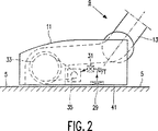
図2に示すように、吸引アタッチメント9の吸引ノズル11は、浄化すべき表面5のタイプを検出するための表面タイプ検出器29を具えている。図2においてのみ概略的に示し、且つ後にさらに詳述する表面タイプ検出器29は、動作中に、浄化すべき表面タイプの特性を示す出力信号UFTを、同じく吸引ノズル11内に位置付けられる電気コントローラ31に転送する。吸引ノズル11にはさらに、電気モータ35によって駆動される、回動自在のブラシ33が設けられている。コントローラ31は、動作中に、電気モータ35及びブラシ33の速度を、出力信号UFTの関数として制御する。従って、ブラシ33の速度は、浄化すべき表面5のタイプに適合させることができ、その結果、真空掃除機の掃除する機能は向上する。なお、真空掃除機の動作は、表面タイプ検出器29の出力信号UFTによって別の態様で制御することもできる。例えば、真空掃除機に、ハウジング1内に収納したコントローラを設け、これによって、吸引ユニット7の吸引力を出力信号UFTの関数として制御することができる。
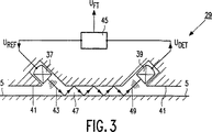
図3に示す、第1の実施例の表面タイプ検出器29は、圧電振動発生器37及び圧電振動検出器39を具えており、これらは本来、通常の既知のものである。吸引ノズル11の下側41には、振動発生器37と振動検出器39とが設けられ、これらの振動発生器37と振動検出器39とが約90°の角度で互いに対向するようにしてある。動作中、振動発生器37は、所定のほぼ一定の振幅値を有する空気振動43を発生する。このために、表面タイプ検出器29は、動作中に、所定の振幅値に対応する出力信号UREFを振動発生器37に供給する電気制御部材45を具えている。吸引ノズル11の下側41は検出空所47を画成し、この空所47は、動作中は浄化すべき表面5によっても画成される。振動発生器37は検出空所47の方を向いているので、動作中に振動発生器37によって発生される空気振動43は検出空所47内を伝播する。図3に示すように、空気振動43は、浄化すべき表面5と吸引ノズル11の下側41とによって検出空所47内で反射され、この反射された空気振動49は振動検出器39によって検出され、この振動検出器39は、反射した空気振動49の振幅値に相当する出力信号UDETを供給する。振動発生器37によって発生された空気振動43は、一部は浄化すべき表面5によって吸収され、そして一部は浄化すべき表面5を経て、浄化すべき表面5の下方にある基面に伝達される。その結果、空気振動43は浄化すべき表面5によって部分的にのみ反射されるので、振動検出器39が測定する、反射空気振動49の振幅値は、振動発生器37によって発生された空気振動43の、元の予定した振幅値よりもはるかに小さくなる。発生された空気振動43が、浄化すべき表面5によって吸収され、伝達され、且つ反射される比率は、浄化すべき表面5のタイプに大いに依存するので、反射された空気振動49の振幅値もまた、浄化すべき表面5のタイプに大いに依存する。振動発生器37が前記所定の振幅値を有する空気振動を発生する際に生じる、反射空気振動49の振幅値のうち、実験的に確かめた多数の値は、浄化すべき表面5の多数のタイプについて、電気制御部材45内に格納される。従って、前記所定の振幅値はある基準値を成し、この基準値に関連して、様々なタイプの浄化すべき表面5によって、反射される空気振動49の振幅値が識別される。制御部材45は、動作中に出力信号UDETと前記格納した値とを比較し、そしてこの比較結果から、当面のタイプの浄化すべき表面5を特定する。振動検出器39の出力信号UDETは浄化すべき表面5のタイプに大いに依存し、且つ表面タイプ検出器29の出力信号UFTは出力信号UDETによって決まるため、表面タイプ検出器29は強い識別能力を有するので、表面タイプ検出器29によって、堅く滑らかな床とカーペットとの識別をし得るだけでなく、例えば、石敷や板張りの床のような多様な滑らかな床の中での識別や、様々な種類のカーペットや畳の中での識別までもが可能となる。振動発生器37及び振動検出器39は、上述の吸引ノズル11の検出空所47内に配置され、従って浄化すべき表面5のすぐ近くにあるため、表面タイプ検出器29の信頼できる動作が達成される。
発生される空気振動43は、少なくとも15,000Hz、例えば約40,000Hzの周波数を有するのが好ましい。このような周波数の空気振動は、真空掃除機のユーザには、全く又はほとんど聞こえず、さらに15,000Hzに満たない周波数を用いた場合よりも、大幅に優れた識別能力が得られる。真空掃除機に存在する通常の音響源、例えば吸引ユニット7、ブラシ33、及び電気モータ35等は、検出空所47内において、15,000Hz以下の周波数を有する空気振動を発生することを確かめた。振動発生器37が発生する空気振動43は、少なくとも15,000Hzの周波数を有するので、表面タイプ検出器29の動作は、真空掃除機の他のコンポーネントによって発生される空気振動によっては実質上影響されることはない。さらに、振動発生器37が、前記他のコンポーネントの空気振動を打ち消す必要がないため、振動発生器37によって発生される空気振動43の所定の振幅値は、制限された状態を維持し得る。
振動発生器37が発生する空気振動43は、ほぼ一定の周波数を有している。しかしながら、表面タイプ検出器29の出力信号UFTは、この場合の振動発生器37及び振動検出器39の温度と、検出空所47の音響特性とに多少左右されることを確かめた。例えば検出空所47の汚れのため、又は吸引ノズル11の下側41と浄化すべき表面5との距離が変化するために、前記音響特性は変化し、このような変化は、たいていは浄化すべき表面5がディープパイルのカーペットである場合に生じがちである。このように他の音響源に依存する状態は、表面タイプ検出器29の信頼性を損ない、且つそれは本発明によれば、振動発生器37が、例えば36,000Hzから40,000Hzまでの範囲のような、所定の範囲内で変化する周波数での空気振動43を発生するように、動作中に制御部材45が振動発生器37を制御することで、斯様な依存性を低減させることができる。そのような変形例では、制御部材45は、振動検出器39の出力信号UDETから、例えば反射された空気振動49の平均振幅値又は最大振幅値を前記範囲内で求め、且つ制御部材45は、こうして求められた平均や最大の振幅値を、浄化すべき表面5の多数の種々のタイプについて制御部材45内に格納されている反射空気振動の振幅値の実験的に確かめた平均値又は最大値と比較する。
図4〜8に示す本発明による表面タイプ検出器の第2、第3、第4、第5及び第6の実施例において、上述した表面タイプ検出器29のコンポーネントに対応するものには、同じ参照番号を付して示してある。図4に概略的に示した、本発明による吸引アタッチメント9で使用する、第2の実施例の表面タイプ検出器51においては、振動発生器37及び振動検出器39は、吸引ノズル11の下側41に設けられた凹所53内に収納されている。凹所53を使用することで、表面タイプ検出器51は、上述した表面タイプ検出器29の検出空所47よりも、検出空所55がかなり大きくなる。図4に概略的に示すように、動作中に振動検出器39に達する空気振動57は、浄化すべき表面5によって実質上専ら反射され、且つ検出空所55の壁部によっては実質上反射されなくなる。これにより、振動検出器39に達する空気振動57の振幅値が、検出空所55の壁部の音響特性によってはほとんど影響されなくなり、これにより表面タイプ検出器51の信頼性は向上する。
図5に概略的に示す、本発明による吸引アタッチメント9に使用する第3の実施例の表面タイプ検出器59においては、振動発生器37及び振動検出器39は、吸引ノズル11の下側41にて、別個のチャネルタイプのキャビティ61、63の中に各々収納されている。チャネルタイプのキャビティ61、63を使用するため、動作中に、振動発生器37によって発生された空気振動65は、浄化すべき表面5の比較的小さな部分67にほぼ完全に向けられ、前記部分67からほぼ完全に振動検出器39まで反射される。これにより、発生された空気振動65の不所望散乱は、可能な限り防止される。発生された空気振動65のこのような散乱があると、例えば、振動発振器37から振動検出器39への直接クロストークを招くことになり、これは表面タイプ検出器59の信頼性を著しく損ねることになる。
図6に概略的に示す、本発明による吸引アタッチメント9に使用する第4の実施例の表面タイプ検出器69においては、振動発生器37及び振動検出器39は、互いに逆向きで、且つ上述した表面タイプ検出器51の場合のように、吸引ノズル11の下側41に設けた凹所71内に配置されている。振動発生器37に隣接して存在する、凹所71の第1側壁73は、表面タイプ検出器69の第1の反射器を成し、この反射器によって、動作中に振動発生器37によって発生される空気振動75は、浄化すべき表面5に反射される。さらに、振動検出器39に隣接して位置する、凹所71の第2側壁77は、表面タイプ検出器69の第2の反射器を成しており、この反射器によって、浄化すべき表面5により反射された空気振動79は、振動検出器39の方へと反射される。前記反射器を使用することによって、振動発生器37及び振動検出器39の相互位置に関して、高い自由度が得られる。図6に示す表面タイプ検出器69においては、この自由度を利用することで、振動発生器37と振動検出器39とを相互に隣接して位置させている。
図7に概略的に示す、本発明による吸引アタッチメント9に使用する、第5の実施例の表面タイプ検出器81においては、振動発生器37及び振動検出器39は、上述した表面タイプ検出器51及び69の場合のように、吸引ノズル11の下側41に設けられた凹所83内に配置されている。表面タイプ検出器81の振動発生器37は、動作中、断続的に空気振動85を発生し、すなわちこの発生器は、空気振動85を、毎回短期間に規則的な間隔で発生する。前記期間は充分に短いため、凹所83及び検出空所55内においては、発生された空気振動85と反射される空気振動87との干渉は、ほとんど生じなくなる。発生された空気振動85は、動作中に、振動発生器37から直接浄化すべき表面5に、そして浄化すべき表面5から直接振動検出器39に全てが向けられるのではなく、実際は部分的に他の方向に散乱されるため、振動発生器37が中断なく空気振動85を発生する場合、凹所83及び検出空所55内において、発生された空気振動85と反射された空気振動87との干渉が生じることになる。このような干渉はあるパターンを有し、そのパターンは、例えば、検出空所55の汚れのため、或いは浄化すべき表面5と振動発生器37及び振動検出器39との距離が変動するために生じる、検出空所55の音響特性の比較的小さな変化に伴って、比較的大きく変化してしまう。さらに、前記パターン内で、空気振動の振幅値には相当大きな差異が生じる。従って、このような干渉は、表面タイプ検出器81の正確さ及び信頼性に悪影響を及ぼすことになる。表面タイプ検出器81の振動発生器37は、常に、比較的短期間しか空気振動85を発生しないため、直接発生された空気振動85は、常に、反射される空気振動87が直接発生された空気振動85と干渉し得る前に、すでに消失されてしまう。発生された空気振動85と反射される空気振動87との間の前記不都合な干渉は、かくして実質上抑制されるため、表面タイプ検出器81の信頼性及び正確さは、大幅に改善される。図7に示すように、表面タイプ検出器81には、さらに並列回路89が設けられ、これは、振動発生器37が収納されているキャビティ91と、振動検出器39が収納されているキャビティ93とを接続している。振動発生器37によって発生された空気振動の一部分85′は、動作中、振動発生器37から振動検出器39まで並列回路89を経て直接に、すなわち浄化すべき表面5を介さないで伝えられる。圧電振動発生器37及び圧電振動検出器39は充分に耐久性があり、そして通常の動作状態のもとでは汚染に対して実質上不感応である。しかしながら、圧電振動発生器37及び圧電振動検出器39の特性は、圧電材料のエイジングのため及び温度変動のために変化し得る。並列回路89を使用することで、反射された空気振動87の振幅値(出力信号UDET)と、発生された空気振動85′の元の振幅値(出力信号UDET,0)との双方を、振動検出器39によって測定することができる。このために並列回路89の長さは、元の、断続的に発生させる空気振動85′と、反射される空気振動87とが、常に異なる瞬時に振動検出器39に達するようにしてある。制御部材45は、出力信号UDETとUDET,0との比を決定し、こうして決定した比を、反射される空気振動の振幅値と発生させる空気振動の元の振幅値との間の、実験的に確かめた比率と比較する。この実験的に確かめた比率は、多数の様々なタイプの浄化すべき表面5について、制御部材45内に格納されている。前記比率は、温度や、振動発生器37及び振動検出器39の何れのエイジングについてもほぼ無関係であるため、このように並列回路89を使用することで、表面タイプ検出器81の信頼性は一層向上する。
図8に概略的に示した、本発明による吸引アタッチメント9にて使用する第6の実施例の表面タイプ検出器95には、圧電振動発生器97が設けられており、これは本来、通常の既知のものであり、且つこれは振動検出器を形成するように切り替えることができる。このように振動発生器97は同時に振動検出器を構成するため、表面タイプ検出器95のコンポーネントの数はかなり減少され、表面タイプ検出器95の構成は著しく単純化される。振動発生器97は、動作中に、上述の表面タイプ検出器81の振動発生器37と同様に、断続的に空気振動99を発生する。短期間中に発生される空気振動99は、常に、主チャネル101を経て浄化すべき表面5に伝えられ、浄化すべき表面5によって反射され、且つ主チャネル101を経て振動発生器97へと逆案内され、その間に振動発生器97は、振動検出器を形成すべく切り替えられる。表面タイプ検出器95には、上述の表面タイプ検出器81のように、並列回路103が設けられている。図8に概略的に示したように、並列回路103はデッドエンドを形成し、そしてこのデッドエンドに隣接して、エンドリフレクタ105が設けられている。動作中、振動発生器97によって短期間中に発生される空気振動の一部分99′は、並列回路103へと案内され、且つ並列回路103のエンドリフレクタ105によって、振動発生器97まで反射され、その間に振動発生器97は、振動検出器を形成すべく切り替えられる。並列回路103の長さは、エンドリフレクタ105によって反射された空気振動107′と、浄化すべき表面5によって反射された空気振動107とが、異なる瞬時に振動発生器97に達するような長さにして、振動発生器97は、上述した表面タイプ検出器81の振動検出器39のように、浄化すべき表面5によって反射された空気振動107の振幅値と、振動発生器97によって発生される空気振動99′の元の振幅値との比率を測定することができるようになる。
なお、本発明は、真空掃除機だけでなく、処理すべき表面のタイプを検出するための表面タイプ検出器を具える、様々な種類の電気表面処理デバイスにも関するものである。この例を挙げると、電気磨き機、床用電気モップ、電気スチームクリーナ、及び電気シャンプーデバイスなどがある。本発明による、このような電気表面処理デバイスにおいては、表面タイプ検出機の出力信号は、例えば、表面処理デバイスの動作を制御する電気制御部材に供給される。電気磨きデバイスでは、例えば、磨きデバイスの磨きブラシの回転速度を、表面タイプ検出器の出力信号の関数として制御することができ、また、例えば電気スチームクリーナや電気シャンプーデバイスでは、供給されるべきスチームの量及びシャンプーの量を、それぞれ、表面タイプ検出器の出力信号の関数として制御することができる。
上述した真空掃除機はフロアタイプの真空掃除機である。なお本発明は、吸引ノズルがチューブを介してハンドルに結合され、同時に、吸引ユニットを内蔵したハウジングが前記チューブに嵌合される、いわゆる縦型掃除機も網羅するものである。また本発明は、例えば、一個又は複数個の吸引アタッチメントを、建物に内蔵した吸引ラインの固定システムの多数の吸引接続ポイントに接続し得る、中央真空掃除設備にも関するものである。
さらにまた、上述した振幅値の代わりに、処理すべき表面によって反射される空気振動の、振幅値とは異なる物理量もまた、本発明による振動検出器によって測定し得る。従って、例えば、振動検出器が、処理すべき表面によって反射された空気振動の周波数スペクトルを測定し得るようにもできる。他の例として、振動している空気の粒子の振動速度を測定することもできる。
さらに、本発明によれば、表面タイプ検出器は、吸引ノズル11内以外の位置に配置することもできる。従って、例えば、表面タイプ検出器をハウジング1内に設けることもでき、この場合、振動発生器37及び振動検出器39はハウジング1の下側に位置させる。
さらにまた、本発明は、使用する表面タイプ検出器が、別個の振動発生器を具えていない電気表面処理デバイスにも関するものである。このような例では、表面タイプ検出器の振動検出器は、例えば、処理すべき表面によって反射される空気振動の振幅値を測定するが、その空気振動は、例えば、真空掃除機の吸引ユニットのような、電気表面処理デバイスの他の音響源から派生する。このような空気振動は、しばしば通常の動作状態のもとでは適度に一定の振幅値を有するため、このような例においては、浄化すべき表面のタイプの、適度に信頼性のある測定が得られる。
最後に、上述した圧電振動発生器37、97及び圧電振動検出器39の代わりに、例えば、本来、通常の既知のものである電気力学振動発生器及び電気力学振動検出器のような、他のタイプの振動発生器及び他のタイプの振動検出器を使用することもできる。
【図面の簡単な説明】
図1は、本発明による電気表面処理デバイスを示す概略図である。
図2は、図1の電気表面処理デバイスに使用される本発明によるアタッチメントの吸引ノズルを示す概略図である。
図3は、図2のアタッチメントに使用される表面タイプ検出器の第1の実施例を示す概略図である。
図4は、図2のアタッチメントに使用される表面タイプ検出器の第2の実施例を示す概略図である。
図5は、図2のアタッチメントに使用される表面タイプ検出器の第3の実施例を示す概略図である。
図6は、図2のアタッチメントに使用される表面タイプ検出器の第4の実施例を示す概略図である。
図7は、図2のアタッチメントに使用される表面タイプ検出器の第5の実施例を示す概略図である。
図8は、図2のアタッチメントに使用される表面タイプ検出器の第6の実施例を示す概略図である。〔Technical field〕
The present invention relates to an electrical surface treatment device comprising a surface type detector for detecting the type of surface to be treated, which surface type detector detects air vibrations reflected by the surface to be treated. And an output signal indicating characteristics of the type of surface to be treated during operation.
The present invention also relates to an attachment suitable for use in the electrical surface treatment device according to the present invention.
An electrical surface treatment device of the type mentioned at the outset, which is configured as a vacuum cleaner and comprises an attachment of the type configured as a suction attachment as described in the second paragraph, is disclosed in European Patent Application Document EP-A-0 372 903. Known vacuum cleaner surface type detectors are acoustic surface type detectors housed in the vacuum cleaner suction attachment. The vibration detector of this surface type detector forms part of the ultrasound system, which measures the distance in operation between the surface to be cleaned and the underside of the suction nozzle of the suction attachment Is possible. If the ultrasound system measures a relatively large distance, the surface type detector provides an output signal that is characteristic of a hard and smooth floor. If the surface to be cleaned is a carpet, the ultrasound system measures a relatively short distance because the edge of the suction nozzle protruding beyond the underside of the suction nozzle partially sinks into the carpet. It will be. In this case, the surface type detector provides an output signal indicative of the characteristics of the carpet. The output signal of the surface type detector in the known vacuum cleaner is used to control the electric motor that rotates the brush placed in the suction nozzle and to control the sensitivity of the optical dust detector of the vacuum cleaner It is done.
A disadvantage of the known electrical surface treatment devices and known attachments is that the surface type detectors used for them have limited identification capabilities, said surface type detectors being essentially exclusively rigid and smooth floors. Only an output signal indicating the characteristics of the carpet and an output signal indicating the characteristics of the carpet can be supplied.
[Disclosure of the Invention]
It is an object of the present invention to provide an electrical surface treatment device and attachment of the kind mentioned at the outset, with a surface type detector having the best possible discrimination ability.
For this purpose, the electrical surface treatment device according to the present invention determines the output signal by the value of a physical quantity of air vibration reflected by the surface to be treated, which can be measured by a vibration detector. It is characterized by doing so.
Air vibrations are generated during operation by, for example, a vibration generator of a surface type detector or some other vibration source present in an electrical surface treatment device. Such air vibrations are partly absorbed by the surface to be treated, partly transmitted through the surface to be treated and partly reflected by the surface to be treated. Therefore, the physical quantity of the air vibration reflected by the surface to be treated is different from the original value of the generated physical quantity of the air vibration. Since the absorption, transmission and reflection of air vibrations by the surface to be treated occurs at a rate that clearly depends on the type of surface to be treated, the value of said physical quantity of air vibrations reflected by the surface to be treated is From the output signal of the surface type detector, the surface type to be processed can be clearly derived. Thus, when this surface type detector is used, for example, in a vacuum cleaner, it not only distinguishes between hard and smooth floors and carpets, but also clearly detects, for example, smooth floor types and carpet types. be able to.
A specific preferred embodiment of the electrical surface treatment device according to the present invention is characterized in that the physical quantity is an amplitude value, and the surface type detector comprises a vibration generator for generating air vibration having a predetermined amplitude value. To do. The predetermined amplitude value of the air vibration that can be generated by the vibration generator forms a reference value, and the surface type detector determines this reference value and the amplitude value of the air vibration reflected by the surface to be treated. Can be compared. This provides an accurate and reliable operation of the surface type detector.
Another preferred embodiment of the electrical surface treatment device according to the invention is characterized in that the vibration generator generates air vibrations at a frequency of at least 15,000 Hz during operation. Under normal operating conditions, electrical surface treatment devices have been found to generate air vibrations at frequencies generally below 15,000 Hz. Since the vibration generated by the vibration generator has a frequency of at least 15,000 Hz, the vibration generator does not need to counteract the air vibration generated by other parts of the electrical surface treatment device, so the vibration generator generates The amplitude value of the air vibration to be maintained can be limited. Furthermore, it was confirmed that the discrimination ability of the surface type detector was much better at frequencies of at least 15,000 Hz than at lower frequencies. Furthermore, air vibrations with a frequency of at least 15,000 Hz are hardly audible to the user of the electrical surface treatment device, or in some cases not audible at all.
Yet another preferred embodiment of the electrical surface treatment device according to the invention is characterized in that the vibration generator generates air vibrations of a frequency that varies within a predetermined range during operation. In this example, the output signal of the surface type detector corresponds, for example, to an average amplitude value or a maximum amplitude value within the said range of air vibrations reflected by the surface to be processed. As a result, the output signal is a parameter other than the type of surface to be treated, such as the distance between the vibration generator and vibration detector and the surface to be treated, the electrical at which the vibration generator and vibration detector are located. It depends on the acoustic properties of a part of the surface treatment device, as well as parameters such as the temperature of the vibration generator and vibration detector, but it has been confirmed that this dependence is only to a limited extent.
Another preferred embodiment of the electrical surface treatment device according to the invention is characterized in that the vibration detector comprises a piezoelectric vibration detector. Such piezoelectric vibration detectors are sufficiently durable under normal operating conditions and are substantially insensitive to contamination.
Another preferred embodiment of the electrical surface treatment device according to the invention is characterized in that the vibration generator comprises a piezoelectric vibration generator. Such a piezoelectric vibration generator is sufficiently durable under normal operating conditions and is substantially insensitive to contamination.
Still another preferred embodiment of the electrical surface treatment device according to the present invention is characterized in that the vibration generator comprises a vibration detector, and the vibration generator can be switched to form a vibration detector. . This greatly reduces the number of surface type detector components, thus simplifying the construction of the surface type detector. When the vibration generator is switched during operation to form a vibration detector, the air vibrations that have just been generated by the vibration generator and reflected by the surface to be processed can be detected by the vibration generator. .
A preferred embodiment of the electrical surface treatment device according to the invention is characterized in that the vibration generator and the vibration detector are opposed to each other at an angle of approximately 90 °. Thus, it was confirmed that a very reliable operation of the surface type detector can be obtained by mutually arranging the vibration generator and the vibration detector.
Yet another preferred embodiment of the electrical surface treatment device according to the invention comprises a first reflector for the surface type detector to reflect air vibrations generated by the vibration generator towards the surface to be treated, And a second reflector for reflecting the air vibrations reflected by the surface to be directed towards the vibration detector. By using the reflector, the degree of freedom is greatly increased with respect to the mutual arrangement of the vibration generator and the vibration detector. The vibration generator and vibration detector in this example can be located next to each other, for example, in close proximity.
Yet another preferred embodiment of the electrical surface treatment device according to the invention is characterized in that the vibration generator intermittently generates air vibrations during operation. In this example, the vibration generator always generates a very short period of air vibration, so that interference between the generated air vibration and the reflected air vibration is prevented as much as possible during operation. Such interference that occurs when the vibration generator generates air vibrations without interruption has a pattern that has caused relatively small changes in the acoustic characteristics of the surface type detector and the surface to be processed. As a result, it will change relatively greatly. Furthermore, a large difference occurs in the amplitude value of the air vibration in the pattern. Thus, the interference has a significant adverse effect on the accuracy and reliability of the surface type detector. The intermittent generation of air vibrations by the vibration generator prevents such interference, thus greatly improving the accuracy and reliability of the surface type detector. Since the vibration generator in this example generates air vibrations each time for a relatively short period of time, if the vibration generator is switched to the function of a vibration detector, the vibration generator Can be used as a vibration detector.
Another preferred embodiment of the electrical surface treatment device according to the invention is that the surface type detector comprises a parallel circuit, through which a part of the air vibrations generated by the vibration generator is directly directed to the vibration detector. It is characterized by being able to do. The characteristics of the vibration generator and vibration detector may change due to aging and temperature fluctuations. The portion of air vibration that is intermittently generated and transmitted through the parallel circuit during operation, and the portion of air vibration that is intermittently generated and guided through the surface to be processed during operation, can be different instantaneously. Reach the vibration detector. Thereby, the vibration detector can measure the ratio between the amplitude value of the air vibration reflected by the surface to be treated and the original amplitude value of the generated air vibration. The ratio is largely independent of the temperature of the vibration generator and vibration detector and any aging thereof. Thus, the air vibrations transmitted through the parallel circuit serve as a reference value, and the surface type detector uses this reference value and the amplitude value of the air vibration reflected by the surface to be processed. Can be compared.
Another preferred embodiment of the electric surface treatment device according to the present invention is characterized in that the parallel circuit has a dead end, and an end reflector for retroreflecting air vibration transmitted to the parallel circuit is provided near the dead end. And In this example, a vibration generator that generates air vibrations intermittently and can be switched to form a vibration detector is used. The part of the air vibration transmitted through the parallel circuit during operation reaches the vibration generator which is reflected back to the parallel circuit by the end reflector and has already been switched to the vibration detector, thus forming a certain reference value. . In this way, a particularly simple and practical construction of the surface type detector is obtained.
An attachment according to the invention, suitable for use in an electrical surface treatment device according to the invention, is characterized in that the surface type detector is housed in the suction nozzle of the attachment. Since the surface type detector is housed in the suction nozzle of the attachment, the surface type detector is in the immediate vicinity of the surface to be processed, so that reliable operation of the surface type detector is achieved.
An attachment suitable for use in an electrical surface treatment device according to the present invention, wherein the surface type detector used in the device comprises a vibration generator that generates air vibrations having a predetermined amplitude value, is a surface type The detector vibration generator and vibration detector are characterized in that they are positioned in operation in a detection cavity defined by the surface to be treated and the underside of the suction nozzle of the attachment. Since the vibration generator and vibration detector are positioned within the detection cavity, the vibration generator and vibration detector are in close proximity to the surface to be processed, and thus reliable operation of the surface type detector is achieved. The Since the acoustic properties of the detection cavity are greatly affected by the type of surface to be processed during operation, the surface type detector will have a strong discrimination capability.
A preferred embodiment of the attachment according to the invention is characterized in that the vibration generator and the vibration detector are located in a recess provided under the suction nozzle. By using the recess, the detection cavity of the surface type detector is expanded, thereby affecting the acoustic properties of the detection cavity. By making the recess into an appropriate shape, the acoustic characteristics of the surface type detector are optimized.
Another preferred embodiment of the attachment according to the invention is characterized in that the vibration generator and the vibration detector are housed in separate channel-type cavities, each provided below the suction nozzle. By using the separate channel type cavities, the air vibrations generated by the vibration generator during operation are almost completely reflected by the surface to be processed, so that the vibration generator directly to the vibration detector. Crosstalk is greatly suppressed.
〔Example〕
In the following, the invention will be described in detail with reference to the drawings.
The electric surface treatment device according to the present invention shown in FIG. 1 is a vacuum cleaner for cleaning the surface. The illustrated vacuum cleaner is a so-called floor type vacuum cleaner comprising a housing 1 which can be moved on a
As shown in FIG. 2, the
The
The generated
The
In the second, third, fourth, fifth, and sixth embodiments of the surface type detector according to the present invention shown in FIGS. 4 to 8, the components corresponding to the components of the
In the
In the
In the
The
It should be noted that the present invention relates not only to vacuum cleaners, but also to various types of electrical surface treatment devices comprising a surface type detector for detecting the type of surface to be treated. Examples include electric polishers, floor mops, electric steam cleaners, and electric shampoo devices. In such an electrical surface treatment device according to the present invention, the output signal of the surface type detector is supplied, for example, to an electrical control member that controls the operation of the surface treatment device. With an electric polishing device, for example, the rotational speed of the polishing brush of the polishing device can be controlled as a function of the output signal of the surface type detector, and with an electric steam cleaner or electric shampoo device, for example, the steam to be supplied And the amount of shampoo can each be controlled as a function of the output signal of the surface type detector.
The vacuum cleaner described above is a floor type vacuum cleaner. The present invention also covers a so-called vertical vacuum cleaner in which a suction nozzle is coupled to a handle via a tube, and at the same time, a housing containing a suction unit is fitted into the tube. The present invention also relates to a central vacuum cleaning facility in which, for example, one or more suction attachments can be connected to a number of suction connection points of a suction line fixing system built in a building.
Furthermore, instead of the amplitude values mentioned above, the physical quantities different from the amplitude values of the air vibrations reflected by the surface to be treated can also be measured by the vibration detector according to the invention. Thus, for example, a vibration detector may be able to measure the frequency spectrum of air vibrations reflected by the surface to be treated. As another example, the vibration velocity of vibrating air particles can be measured.
Furthermore, according to the present invention, the surface type detector can be arranged at a position other than the inside of the
Furthermore, the invention relates to an electrical surface treatment device in which the surface type detector used does not comprise a separate vibration generator. In such an example, the vibration detector of the surface type detector measures, for example, the amplitude value of the air vibrations reflected by the surface to be processed, which air vibrations are, for example, those of the suction unit of the vacuum cleaner. Derived from other acoustic sources such as electrical surface treatment devices. Such air vibrations often have a reasonably constant amplitude value under normal operating conditions, so in these cases a reasonably reliable measurement of the type of surface to be cleaned is obtained. It is done.
Finally, instead of the above-described
[Brief description of the drawings]
FIG. 1 is a schematic diagram illustrating an electrical surface treatment device according to the present invention.
FIG. 2 is a schematic view showing a suction nozzle of an attachment according to the present invention used in the electric surface treatment device of FIG.
FIG. 3 is a schematic diagram showing a first embodiment of a surface type detector used in the attachment of FIG.
FIG. 4 is a schematic diagram showing a second embodiment of the surface type detector used in the attachment of FIG.
FIG. 5 is a schematic view showing a third embodiment of the surface type detector used in the attachment of FIG.
FIG. 6 is a schematic view showing a fourth embodiment of the surface type detector used in the attachment of FIG.
FIG. 7 is a schematic view showing a fifth embodiment of the surface type detector used in the attachment of FIG.
FIG. 8 is a schematic view showing a sixth embodiment of the surface type detector used in the attachment of FIG.
Claims (12)
Applications Claiming Priority (3)
| Application Number | Priority Date | Filing Date | Title |
|---|---|---|---|
| EP97202623 | 1997-08-25 | ||
| EP97202623.1 | 1997-08-25 | ||
| PCT/IB1998/000996 WO1999009874A1 (en) | 1997-08-25 | 1998-06-29 | Electrical surface treatment device with an acoustic surface type detector |
Related Child Applications (1)
| Application Number | Title | Priority Date | Filing Date |
|---|---|---|---|
| JP2008249909A Division JP4829282B2 (en) | 1997-08-25 | 2008-09-29 | Electrical surface treatment device with acoustic surface type detector |
Publications (3)
| Publication Number | Publication Date |
|---|---|
| JP2001504744A JP2001504744A (en) | 2001-04-10 |
| JP2001504744A5 JP2001504744A5 (en) | 2006-01-05 |
| JP4282772B2 true JP4282772B2 (en) | 2009-06-24 |
Family
ID=8228678
Family Applications (2)
| Application Number | Title | Priority Date | Filing Date |
|---|---|---|---|
| JP51409199A Expired - Lifetime JP4282772B2 (en) | 1997-08-25 | 1998-06-29 | Electrical surface treatment device with acoustic surface type detector |
| JP2008249909A Expired - Lifetime JP4829282B2 (en) | 1997-08-25 | 2008-09-29 | Electrical surface treatment device with acoustic surface type detector |
Family Applications After (1)
| Application Number | Title | Priority Date | Filing Date |
|---|---|---|---|
| JP2008249909A Expired - Lifetime JP4829282B2 (en) | 1997-08-25 | 2008-09-29 | Electrical surface treatment device with acoustic surface type detector |
Country Status (7)
| Country | Link |
|---|---|
| US (1) | US6076227A (en) |
| EP (1) | EP0939598B2 (en) |
| JP (2) | JP4282772B2 (en) |
| KR (1) | KR100516315B1 (en) |
| CN (1) | CN1155326C (en) |
| DE (1) | DE69832957T3 (en) |
| WO (1) | WO1999009874A1 (en) |
Families Citing this family (67)
| Publication number | Priority date | Publication date | Assignee | Title |
|---|---|---|---|---|
| US8788092B2 (en) | 2000-01-24 | 2014-07-22 | Irobot Corporation | Obstacle following sensor scheme for a mobile robot |
| US8412377B2 (en) | 2000-01-24 | 2013-04-02 | Irobot Corporation | Obstacle following sensor scheme for a mobile robot |
| US6956348B2 (en) | 2004-01-28 | 2005-10-18 | Irobot Corporation | Debris sensor for cleaning apparatus |
| US6690134B1 (en) | 2001-01-24 | 2004-02-10 | Irobot Corporation | Method and system for robot localization and confinement |
| US7571511B2 (en) | 2002-01-03 | 2009-08-11 | Irobot Corporation | Autonomous floor-cleaning robot |
| US6810305B2 (en) * | 2001-02-16 | 2004-10-26 | The Procter & Gamble Company | Obstruction management system for robots |
| US7663333B2 (en) | 2001-06-12 | 2010-02-16 | Irobot Corporation | Method and system for multi-mode coverage for an autonomous robot |
| US8396592B2 (en) | 2001-06-12 | 2013-03-12 | Irobot Corporation | Method and system for multi-mode coverage for an autonomous robot |
| WO2003026474A2 (en) * | 2001-09-26 | 2003-04-03 | Friendly Robotics Ltd. | Robotic vacuum cleaner |
| IL145680A0 (en) | 2001-09-26 | 2002-06-30 | Friendly Robotics Ltd | Robotic vacuum cleaner |
| US9128486B2 (en) | 2002-01-24 | 2015-09-08 | Irobot Corporation | Navigational control system for a robotic device |
| US8428778B2 (en) | 2002-09-13 | 2013-04-23 | Irobot Corporation | Navigational control system for a robotic device |
| US8386081B2 (en) | 2002-09-13 | 2013-02-26 | Irobot Corporation | Navigational control system for a robotic device |
| US7599758B2 (en) | 2003-09-19 | 2009-10-06 | Royal Appliance Mfg. Co. | Sensors and associated methods for controlling a vacuum cleaner |
| US7237298B2 (en) | 2003-09-19 | 2007-07-03 | Royal Appliance Mfg. Co. | Sensors and associated methods for controlling a vacuum cleaner |
| US7424766B2 (en) | 2003-09-19 | 2008-09-16 | Royal Appliance Mfg. Co. | Sensors and associated methods for controlling a vacuum cleaner |
| US7332890B2 (en) | 2004-01-21 | 2008-02-19 | Irobot Corporation | Autonomous robot auto-docking and energy management systems and methods |
| KR20110009270A (en) * | 2004-01-28 | 2011-01-27 | 아이로보트 코퍼레이션 | Debris sensor for cleaning apparatus |
| DE102004010827B4 (en) * | 2004-02-27 | 2006-01-05 | Alfred Kärcher Gmbh & Co. Kg | Soil cultivation device and method for its control |
| US7720554B2 (en) | 2004-03-29 | 2010-05-18 | Evolution Robotics, Inc. | Methods and apparatus for position estimation using reflected light sources |
| EP1776624A1 (en) | 2004-06-24 | 2007-04-25 | iRobot Corporation | Programming and diagnostic tool for a mobile robot |
| US8972052B2 (en) | 2004-07-07 | 2015-03-03 | Irobot Corporation | Celestial navigation system for an autonomous vehicle |
| US7706917B1 (en) | 2004-07-07 | 2010-04-27 | Irobot Corporation | Celestial navigation system for an autonomous robot |
| KR101084122B1 (en) * | 2004-07-30 | 2011-11-17 | 엘지전자 주식회사 | Suction nozzle for vacuum cleaner |
| US7620476B2 (en) | 2005-02-18 | 2009-11-17 | Irobot Corporation | Autonomous surface cleaning robot for dry cleaning |
| US8670866B2 (en) | 2005-02-18 | 2014-03-11 | Irobot Corporation | Autonomous surface cleaning robot for wet and dry cleaning |
| US8392021B2 (en) | 2005-02-18 | 2013-03-05 | Irobot Corporation | Autonomous surface cleaning robot for wet cleaning |
| US8930023B2 (en) | 2009-11-06 | 2015-01-06 | Irobot Corporation | Localization by learning of wave-signal distributions |
| US20070017061A1 (en) * | 2005-07-20 | 2007-01-25 | Jason Yan | Steering control sensor for an automatic vacuum cleaner |
| EP2816434A3 (en) | 2005-12-02 | 2015-01-28 | iRobot Corporation | Autonomous coverage robot |
| ES2522926T3 (en) | 2005-12-02 | 2014-11-19 | Irobot Corporation | Autonomous Cover Robot |
| US8584305B2 (en) | 2005-12-02 | 2013-11-19 | Irobot Corporation | Modular robot |
| ATE534941T1 (en) | 2005-12-02 | 2011-12-15 | Irobot Corp | COVER ROBOT MOBILITY |
| EP2533120B1 (en) | 2005-12-02 | 2019-01-16 | iRobot Corporation | Robot system |
| EP1996987B1 (en) | 2006-03-17 | 2018-10-31 | iRobot Corporation | Robot confinement |
| EP2023788B1 (en) | 2006-05-19 | 2011-09-07 | iRobot Corporation | Removing debris from cleaning robots |
| US8417383B2 (en) | 2006-05-31 | 2013-04-09 | Irobot Corporation | Detecting robot stasis |
| KR101393196B1 (en) | 2007-05-09 | 2014-05-08 | 아이로보트 코퍼레이션 | Compact autonomous coverage robot |
| CN108378771B (en) | 2010-02-16 | 2021-06-11 | 艾罗伯特公司 | Vacuum cleaner brush |
| EP2659260B1 (en) | 2010-12-30 | 2019-11-20 | iRobot Corporation | Debris monitoring |
| US11471020B2 (en) | 2011-04-29 | 2022-10-18 | Irobot Corporation | Robotic vacuum cleaning system |
| US9220386B2 (en) | 2011-04-29 | 2015-12-29 | Irobot Corporation | Robotic vacuum |
| JP2014236838A (en) * | 2013-06-07 | 2014-12-18 | シャープ株式会社 | Self-propelled vacuum cleaner |
| DE102013223864A1 (en) * | 2013-11-21 | 2015-05-21 | BSH Hausgeräte GmbH | Method of operating a vacuum cleaner and vacuum cleaner |
| AU2015241429B2 (en) | 2014-03-31 | 2018-12-06 | Irobot Corporation | Autonomous mobile robot |
| US9516806B2 (en) | 2014-10-10 | 2016-12-13 | Irobot Corporation | Robotic lawn mowing boundary determination |
| US9510505B2 (en) | 2014-10-10 | 2016-12-06 | Irobot Corporation | Autonomous robot localization |
| US9420741B2 (en) | 2014-12-15 | 2016-08-23 | Irobot Corporation | Robot lawnmower mapping |
| US9538702B2 (en) | 2014-12-22 | 2017-01-10 | Irobot Corporation | Robotic mowing of separated lawn areas |
| US11115798B2 (en) | 2015-07-23 | 2021-09-07 | Irobot Corporation | Pairing a beacon with a mobile robot |
| US10034421B2 (en) | 2015-07-24 | 2018-07-31 | Irobot Corporation | Controlling robotic lawnmowers |
| US10021830B2 (en) | 2016-02-02 | 2018-07-17 | Irobot Corporation | Blade assembly for a grass cutting mobile robot |
| US10459063B2 (en) | 2016-02-16 | 2019-10-29 | Irobot Corporation | Ranging and angle of arrival antenna system for a mobile robot |
| US10512384B2 (en) | 2016-12-15 | 2019-12-24 | Irobot Corporation | Cleaning roller for cleaning robots |
| DE102017101936A1 (en) * | 2017-02-01 | 2018-08-02 | Vorwerk & Co. Interholding Gesellschaft mit beschränkter Haftung | Automatically movable soil tillage implement |
| US11470774B2 (en) | 2017-07-14 | 2022-10-18 | Irobot Corporation | Blade assembly for a grass cutting mobile robot |
| US10595624B2 (en) | 2017-07-25 | 2020-03-24 | Irobot Corporation | Cleaning roller for cleaning robots |
| DE102017116747A1 (en) * | 2017-07-25 | 2019-01-31 | Vorwerk & Co. Interholding Gmbh | Floor cleaning device and method for its operation |
| EP3740109A1 (en) | 2018-01-17 | 2020-11-25 | Techtronic Floor Care Technology Limited | System and method for operating a cleaning system based on a surface to be cleaned |
| US11109727B2 (en) | 2019-02-28 | 2021-09-07 | Irobot Corporation | Cleaning rollers for cleaning robots |
| CN109907703A (en) * | 2019-04-04 | 2019-06-21 | 珠海市一微半导体有限公司 | A kind of mobile robot |
| CN110018239B (en) * | 2019-04-04 | 2022-07-08 | 珠海一微半导体股份有限公司 | Carpet detection method |
| CN110514744B (en) * | 2019-08-20 | 2020-05-05 | 珠海市一微半导体有限公司 | Correction method and detection method for judgment threshold of ground medium |
| CN110403540A (en) * | 2019-08-20 | 2019-11-05 | 珠海市一微半导体有限公司 | Toning equipment and clean robot for the detection of ground medium |
| CN110477814B (en) * | 2019-08-20 | 2023-08-15 | 珠海一微半导体股份有限公司 | Mobile robot for carpet detection |
| CN114980787B (en) | 2020-03-25 | 2024-01-26 | 科德宝两合公司 | Method and assembly for identifying a substrate |
| CN112198222B (en) * | 2020-09-17 | 2022-04-05 | 美智纵横科技有限责任公司 | Ground material identification method, system, equipment and storage medium |
Family Cites Families (19)
| Publication number | Priority date | Publication date | Assignee | Title |
|---|---|---|---|---|
| US4574637A (en) * | 1984-08-03 | 1986-03-11 | Univ Ohio | Method for measuring surface and near surface properties of materials |
| JP2606842B2 (en) * | 1987-05-30 | 1997-05-07 | 株式会社東芝 | Electric vacuum cleaner |
| JPS63300732A (en) * | 1987-05-30 | 1988-12-07 | 株式会社東芝 | Electric cleaner |
| JP2820407B2 (en) † | 1988-02-16 | 1998-11-05 | 松下電器産業株式会社 | Self-propelled vacuum cleaner |
| KR910006885B1 (en) * | 1988-08-15 | 1991-09-10 | 미쯔비시 덴끼 가부시기가이샤 | Floor detector for vacuum cleaners |
| JPH02102629A (en) | 1988-10-11 | 1990-04-16 | Mitsubishi Electric Corp | Vacuum cleaner |
| JPH0824652B2 (en) * | 1988-12-06 | 1996-03-13 | 松下電器産業株式会社 | Electric vacuum cleaner |
| US5144715A (en) * | 1989-08-18 | 1992-09-08 | Matsushita Electric Industrial Co., Ltd. | Vacuum cleaner and method of determining type of floor surface being cleaned thereby |
| JPH0377519A (en) † | 1989-08-18 | 1991-04-03 | Matsushita Electric Ind Co Ltd | Floor surface discriminator |
| DE69015557D1 (en) * | 1989-10-18 | 1995-02-09 | Hitachi Ltd | Vacuum cleaner and method for regulating the same. |
| JPH03212249A (en) † | 1990-01-17 | 1991-09-17 | Matsushita Electric Ind Co Ltd | Floor surface judging device |
| KR920007588B1 (en) † | 1990-08-29 | 1992-09-08 | 주식회사 금성사 | Electric vacuum cleaner |
| JPH04126115A (en) † | 1990-09-18 | 1992-04-27 | Sanyo Electric Co Ltd | Vacuum cleaner |
| JP2900595B2 (en) * | 1990-11-22 | 1999-06-02 | 松下電器産業株式会社 | Vacuum cleaner |
| JPH06261853A (en) † | 1993-03-11 | 1994-09-20 | Matsushita Electric Ind Co Ltd | Floor surface detector for vacuum cleaner |
| FR2708188A1 (en) * | 1993-07-28 | 1995-02-03 | Philips Laboratoire Electroniq | Vacuum cleaner with means of soil detection and adjustment of the engine power according to the detected soil. |
| DE4333645A1 (en) † | 1993-10-02 | 1995-04-06 | Rossendorf Forschzent | Method for minimizing the influence of resonance fluctuations on the measurement signal in ultrasound transmission tests |
| JPH07313418A (en) † | 1994-05-30 | 1995-12-05 | Nippon Ceramic Co Ltd | Vacuum cleaner |
| DE4418887C1 (en) † | 1994-05-30 | 1995-04-06 | Siemens Ag | Method for producing an ultrasonic transducer arrangement |
-
1998
- 1998-06-29 EP EP98925883A patent/EP0939598B2/en not_active Expired - Lifetime
- 1998-06-29 DE DE69832957T patent/DE69832957T3/en not_active Expired - Lifetime
- 1998-06-29 KR KR10-1999-7003583A patent/KR100516315B1/en not_active IP Right Cessation
- 1998-06-29 WO PCT/IB1998/000996 patent/WO1999009874A1/en active IP Right Grant
- 1998-06-29 JP JP51409199A patent/JP4282772B2/en not_active Expired - Lifetime
- 1998-06-29 CN CNB988015714A patent/CN1155326C/en not_active Expired - Lifetime
- 1998-08-17 US US09/135,366 patent/US6076227A/en not_active Expired - Lifetime
-
2008
- 2008-09-29 JP JP2008249909A patent/JP4829282B2/en not_active Expired - Lifetime
Also Published As
| Publication number | Publication date |
|---|---|
| DE69832957T3 (en) | 2013-11-21 |
| KR20000068829A (en) | 2000-11-25 |
| KR100516315B1 (en) | 2005-09-23 |
| DE69832957D1 (en) | 2006-02-02 |
| WO1999009874A1 (en) | 1999-03-04 |
| EP0939598B2 (en) | 2013-03-20 |
| US6076227A (en) | 2000-06-20 |
| CN1242692A (en) | 2000-01-26 |
| EP0939598B1 (en) | 2005-12-28 |
| EP0939598A1 (en) | 1999-09-08 |
| CN1155326C (en) | 2004-06-30 |
| DE69832957T2 (en) | 2006-08-24 |
| JP2001504744A (en) | 2001-04-10 |
| JP2009050710A (en) | 2009-03-12 |
| JP4829282B2 (en) | 2011-12-07 |
Similar Documents
| Publication | Publication Date | Title |
|---|---|---|
| JP4282772B2 (en) | Electrical surface treatment device with acoustic surface type detector | |
| KR102015325B1 (en) | Robot cleaner and method for controlling the same | |
| US10881257B2 (en) | Cleaner and method for controlling cleaner | |
| JP2606842B2 (en) | Electric vacuum cleaner | |
| US6389329B1 (en) | Mobile robots and their control system | |
| JP4542628B2 (en) | Vacuum cleaner with output control depending on operating mode of electric brush | |
| US6532404B2 (en) | Mobile robots and their control system | |
| US5400466A (en) | Vacuum cleaner with air vibration suction nozzle | |
| KR102386699B1 (en) | Cleaner and Controlling method | |
| JPH0759697A (en) | Vacuum cleaner | |
| JPH0838409A (en) | Vacuum cleaner | |
| JPH03212249A (en) | Floor surface judging device | |
| KR101479238B1 (en) | Robot cleaner and control method of the same of | |
| JPH02180236A (en) | Control device of vacuum cleaner | |
| JPH04215733A (en) | Cleaner | |
| JPS63300732A (en) | Electric cleaner | |
| JPS63300731A (en) | Electric cleaner | |
| EP1343406B1 (en) | A control method for a vacuum cleaner | |
| JPH0377519A (en) | Floor surface discriminator | |
| JP2011172746A (en) | Vacuum cleaner | |
| JPH0759686A (en) | Vacuum cleaner | |
| JPH01232255A (en) | Floor surface discriminator | |
| JPH04126115A (en) | Vacuum cleaner | |
| JPH07255654A (en) | Vacuum cleaner | |
| KR20240008461A (en) | Vacuum cleaner and method for controlling thereof |
Legal Events
| Date | Code | Title | Description |
|---|---|---|---|
| A521 | Request for written amendment filed |
Free format text: JAPANESE INTERMEDIATE CODE: A523 Effective date: 20050627 |
|
| A621 | Written request for application examination |
Free format text: JAPANESE INTERMEDIATE CODE: A621 Effective date: 20050627 |
|
| RD02 | Notification of acceptance of power of attorney |
Free format text: JAPANESE INTERMEDIATE CODE: A7422 Effective date: 20070402 |
|
| A131 | Notification of reasons for refusal |
Free format text: JAPANESE INTERMEDIATE CODE: A131 Effective date: 20070814 |
|
| A601 | Written request for extension of time |
Free format text: JAPANESE INTERMEDIATE CODE: A601 Effective date: 20071113 |
|
| A602 | Written permission of extension of time |
Free format text: JAPANESE INTERMEDIATE CODE: A602 Effective date: 20071221 |
|
| RD04 | Notification of resignation of power of attorney |
Free format text: JAPANESE INTERMEDIATE CODE: A7424 Effective date: 20080124 |
|
| A521 | Request for written amendment filed |
Free format text: JAPANESE INTERMEDIATE CODE: A523 Effective date: 20080214 |
|
| A02 | Decision of refusal |
Free format text: JAPANESE INTERMEDIATE CODE: A02 Effective date: 20080701 |
|
| A521 | Request for written amendment filed |
Free format text: JAPANESE INTERMEDIATE CODE: A523 Effective date: 20080929 |
|
| A911 | Transfer to examiner for re-examination before appeal (zenchi) |
Free format text: JAPANESE INTERMEDIATE CODE: A911 Effective date: 20081127 |
|
| TRDD | Decision of grant or rejection written | ||
| A01 | Written decision to grant a patent or to grant a registration (utility model) |
Free format text: JAPANESE INTERMEDIATE CODE: A01 Effective date: 20090217 |
|
| A01 | Written decision to grant a patent or to grant a registration (utility model) |
Free format text: JAPANESE INTERMEDIATE CODE: A01 |
|
| A61 | First payment of annual fees (during grant procedure) |
Free format text: JAPANESE INTERMEDIATE CODE: A61 Effective date: 20090318 |
|
| R150 | Certificate of patent or registration of utility model |
Free format text: JAPANESE INTERMEDIATE CODE: R150 |
|
| FPAY | Renewal fee payment (event date is renewal date of database) |
Free format text: PAYMENT UNTIL: 20120327 Year of fee payment: 3 |
|
| FPAY | Renewal fee payment (event date is renewal date of database) |
Free format text: PAYMENT UNTIL: 20130327 Year of fee payment: 4 |
|
| FPAY | Renewal fee payment (event date is renewal date of database) |
Free format text: PAYMENT UNTIL: 20140327 Year of fee payment: 5 |
|
| R250 | Receipt of annual fees |
Free format text: JAPANESE INTERMEDIATE CODE: R250 |
|
| R250 | Receipt of annual fees |
Free format text: JAPANESE INTERMEDIATE CODE: R250 |
|
| R250 | Receipt of annual fees |
Free format text: JAPANESE INTERMEDIATE CODE: R250 |
|
| R250 | Receipt of annual fees |
Free format text: JAPANESE INTERMEDIATE CODE: R250 |
|
| R250 | Receipt of annual fees |
Free format text: JAPANESE INTERMEDIATE CODE: R250 |
|
| EXPY | Cancellation because of completion of term |