JP4281069B2 - Two-way clutch - Google Patents
Two-way clutch Download PDFInfo
- Publication number
- JP4281069B2 JP4281069B2 JP2007035277A JP2007035277A JP4281069B2 JP 4281069 B2 JP4281069 B2 JP 4281069B2 JP 2007035277 A JP2007035277 A JP 2007035277A JP 2007035277 A JP2007035277 A JP 2007035277A JP 4281069 B2 JP4281069 B2 JP 4281069B2
- Authority
- JP
- Japan
- Prior art keywords
- piece
- shaft member
- shaft
- retainer
- hardness material
- Prior art date
- Legal status (The legal status is an assumption and is not a legal conclusion. Google has not performed a legal analysis and makes no representation as to the accuracy of the status listed.)
- Active
Links
- 230000002457 bidirectional effect Effects 0.000 claims description 41
- 239000000463 material Substances 0.000 claims description 27
- 230000002093 peripheral effect Effects 0.000 claims description 19
- 238000005096 rolling process Methods 0.000 claims description 17
- 239000011347 resin Substances 0.000 claims description 9
- 229920005989 resin Polymers 0.000 claims description 9
- 239000002184 metal Substances 0.000 claims description 5
- 229910052751 metal Inorganic materials 0.000 claims description 5
- 239000000919 ceramic Substances 0.000 claims description 3
- 239000002131 composite material Substances 0.000 claims description 2
- 238000004519 manufacturing process Methods 0.000 description 11
- XEEYBQQBJWHFJM-UHFFFAOYSA-N Iron Chemical compound [Fe] XEEYBQQBJWHFJM-UHFFFAOYSA-N 0.000 description 4
- 238000005192 partition Methods 0.000 description 4
- 230000007774 longterm Effects 0.000 description 3
- 229910000760 Hardened steel Inorganic materials 0.000 description 2
- 230000009471 action Effects 0.000 description 2
- 230000005484 gravity Effects 0.000 description 2
- 229910052742 iron Inorganic materials 0.000 description 2
- 239000004973 liquid crystal related substance Substances 0.000 description 2
- 239000007769 metal material Substances 0.000 description 2
- 125000002066 L-histidyl group Chemical group [H]N1C([H])=NC(C([H])([H])[C@](C(=O)[*])([H])N([H])[H])=C1[H] 0.000 description 1
- 229910000831 Steel Inorganic materials 0.000 description 1
- 230000002238 attenuated effect Effects 0.000 description 1
- 230000004323 axial length Effects 0.000 description 1
- 230000008901 benefit Effects 0.000 description 1
- 229910010293 ceramic material Inorganic materials 0.000 description 1
- 238000013016 damping Methods 0.000 description 1
- 230000007246 mechanism Effects 0.000 description 1
- 230000004048 modification Effects 0.000 description 1
- 238000012986 modification Methods 0.000 description 1
- 238000004080 punching Methods 0.000 description 1
- 239000010959 steel Substances 0.000 description 1
- 238000004804 winding Methods 0.000 description 1
Images


Landscapes
- One-Way And Automatic Clutches, And Combinations Of Different Clutches (AREA)
- Mechanical Operated Clutches (AREA)
Description
本発明は、軸部材の一方向への回転を許容して他方向への回転を阻止するも、所定以上のトルクを付与することにより、軸部材の他方向への回転を可能とし、この状態では逆に一方向への回転を阻止する、いわゆる双方向クラッチに関する。 The present invention allows rotation in one direction of the shaft member and prevents rotation in the other direction, but enables rotation in the other direction of the shaft member by applying a torque exceeding a predetermined value. In contrast, the present invention relates to a so-called bidirectional clutch that prevents rotation in one direction.
上述したような双方向クラッチは、上下に開閉動を行なう蓋や扉、例えば、ノート型パーソナルコンピュータの蓋のヒンジ部、等で使用される。このようなパーソナルコンピュータでは、蓋の内面側には液晶パネル等の表示部があり、該蓋を開けたとき、液晶パネルを任意の角度位置で保持させることが必要である。即ち、双方向クラッチは、パーソナルコンピュータのオペレータが比較的小さな力で蓋を回動させ得るだけでなく、任意の回動位置で静止し得るようにするために使用されるものである。 The bidirectional clutch as described above is used in a lid or a door that opens and closes up and down, for example, a hinge portion of a lid of a notebook personal computer. In such a personal computer, there is a display unit such as a liquid crystal panel on the inner surface side of the lid, and it is necessary to hold the liquid crystal panel at an arbitrary angular position when the lid is opened. That is, the bidirectional clutch is used not only to allow the operator of the personal computer to rotate the lid with a relatively small force but also to stand still at an arbitrary rotation position.
双方向クラッチのその他の用途としては、水平方向の軸部材の周りで回動し得るようなった扉を持つ家具や戸棚等も挙げられる。即ち、扉を重力に抗して開けたとき、該扉を任意の回動位置で停止させるために双方向クラッチを使用することができる。 Other uses of the bi-directional clutch include furniture and cupboards that have doors that can rotate around a horizontal shaft member. That is, when the door is opened against gravity, a bidirectional clutch can be used to stop the door at an arbitrary rotational position.
従来の双方向クラッチとしては、例えば、特許文献1、2及び3に開示されているものが知られている。
これら従来の双方向クラッチは、軸部材を挿通可能な中央開口を有する複数のプレート部材と、各プレート部材の中央開口の内端面と係止可能に軸部材の外周面に沿って等間隔で配設されたニードルローラ(以下単にニードルと称する)とを具備している。 These conventional two-way clutches are arranged at equal intervals along the outer peripheral surface of the shaft member so that they can be engaged with a plurality of plate members having a central opening through which the shaft member can be inserted, and the inner end surface of the central opening of each plate member. And a provided needle roller (hereinafter simply referred to as a needle).
複数のプレート部材は、互いに同じ形状を持ち、中央開口の内端面が軸部材の軸線に沿って略同一面を形成するように整列させた積層状態で使用される。双方向クラッチの軸線に直交する方向での断面において、断面円形の軸部材に対し、これを囲む各プレート部材は、軸部材に面する内端面が直線ないし略直線形で、かつ外端面が内側に湾曲した凹面形の断面形状を有する細肉部を、軸部材の外周面に沿って等間隔で複数箇所に有する。このプレート部材の細肉部は径方向への外力の作用により、僅かながら一時的に変形可能かつ原形復帰可能な弾性を備える。 The plurality of plate members have the same shape as each other, and are used in a stacked state in which the inner end surfaces of the central opening are aligned so as to form substantially the same surface along the axis of the shaft member. In the cross section in the direction perpendicular to the axis of the bidirectional clutch, each plate member surrounding the shaft member having a circular cross section has a straight or substantially straight inner end surface facing the shaft member and an outer end surface on the inner side. A thin-walled portion having a concave cross-sectional shape that is curved at a plurality of positions at equal intervals along the outer peripheral surface of the shaft member. The thin portion of the plate member has elasticity that can be slightly deformed and restored to its original shape slightly by the action of an external force in the radial direction.
従来の双方向クラッチは、更に、このプレート部材の細肉部と接する位置にニードルを保持するためのリテーナを備えている。ニードルは、リテーナにより、軸部材の外周面と
プレート部材の細肉部の内端面とリテーナの側面とにより囲まれたポケット部に保持される。ポケット部は、軸部材の円周方向の中央部に、軸部材の外周円弧とプレート部材の細肉部内端面の略直線形との関係により、軸部材の外周面とプレート部材の細肉部の内端面との距離が最も短い狭窄部を有し、この狭窄部の両側は両者間の距離が逆テーパー状に拡開して拡開部が形成されている。
The conventional bidirectional clutch further includes a retainer for holding the needle at a position in contact with the thin portion of the plate member. The needle is held by the retainer in a pocket portion surrounded by the outer peripheral surface of the shaft member, the inner end surface of the thin portion of the plate member, and the side surface of the retainer. The pocket portion is formed at the central portion of the shaft member in the circumferential direction by the relationship between the outer peripheral arc of the shaft member and the substantially linear shape of the inner end surface of the thin member of the plate member, A narrowed portion having the shortest distance from the inner end surface is formed, and on both sides of the narrowed portion, the distance between both is widened in a reverse taper shape to form widened portions.
狭窄部における軸部材の外周面とプレート部材の細肉部の内端面との距離は、ニードルの径よりも小さく設定されている。また、拡開部は狭窄部から最も離れた部分が、軸部材の外周面とプレート部材の細肉部の内端面との距離がニードルの径よりも大きく設定されている。なお、リテーナには、ニードルを狭窄部方向に付勢するバネ部材が備えられている。 The distance between the outer peripheral surface of the shaft member in the narrowed portion and the inner end surface of the thin portion of the plate member is set smaller than the diameter of the needle. Further, the widest portion of the expanded portion is set such that the distance between the outer peripheral surface of the shaft member and the inner end surface of the thin portion of the plate member is larger than the diameter of the needle. The retainer is provided with a spring member that urges the needle toward the narrowed portion.
次に、以上で述べた従来の双方向クラッチの動作について説明する。
軸部材に対してニードルをポケット部の狭窄部に向かって移動させる方向にトルクが加わると、狭窄部における軸部材の外周面とプレート部材の細肉部の内端面との間の距離がニードルの径よりも小さいため、ニードルは軸部材に制動力を付与する。即ち、ニードルは軸部材の回転に伴なって転動しつつ狭窄部に楔のように食い込み、ニードルと軸部材との間に大なる摩擦力を生ぜしめ、この摩擦力が制動力として軸部材に作用する。このとき、
ニードルを付勢するバネ部材は、ニードルによる軸部材に対する制動動作の確実性を高める作用を果たす。しかしながら、上述のトルクが所定値を超えたとき、ニードルはプレート部材の細肉部を弾性変形させ、狭窄部を押し広げて反対側に移動する。
Next, the operation of the conventional bidirectional clutch described above will be described.
When torque is applied to the shaft member in the direction of moving the needle toward the constriction portion of the pocket portion, the distance between the outer peripheral surface of the shaft member and the inner end surface of the thin portion of the plate member in the constriction portion is Since the diameter is smaller than the diameter, the needle applies a braking force to the shaft member. That is, the needle rolls with the rotation of the shaft member and bites into the constricted portion like a wedge, generating a large frictional force between the needle and the shaft member, and this frictional force is used as a braking force as the shaft member. Act on. At this time,
The spring member that urges the needle serves to increase the certainty of the braking operation on the shaft member by the needle. However, when the above torque exceeds a predetermined value, the needle elastically deforms the thin portion of the plate member, expands the narrow portion, and moves to the opposite side.
一方、軸部材に対してニードルがポケット部の狭窄部から離れる方向にトルクが加えられたときには、ニードルはバネ部材の弾発力に抗しつつ拡開部に留まり、拡開部内で空転し、該軸部材に上述したような制動力が作用することはない。 On the other hand, when torque is applied to the shaft member in a direction away from the narrowed portion of the pocket portion, the needle stays in the expanded portion while resisting the elastic force of the spring member, and idles in the expanded portion. The braking force as described above does not act on the shaft member.
かくして、以上に述べたような双方向クラッチが、例えばノート型パーソナルコンピュータの蓋のヒンジ部で使用された場合を想定すると、操作者が手で蓋をその閉鎖位置から開くとき、蓋の回動については比較的小さな力で行うことが可能であり、蓋が任意の角度位置まで回動させた後に操作者が蓋から手を離したとき、上述した制動力が働き、このため蓋は該角度位置に保持されることになる。また、蓋を閉鎖位置に向かって比較的大きな力で押し込むと、ニードルはプレート部材の細肉部を弾性変形させて狭窄部を押し広げて転動を開始するため、上述の制動力が解除され、これにより蓋は元の閉鎖位置に戻ることになる。 Thus, assuming that the two-way clutch as described above is used, for example, at the hinge part of the lid of a notebook personal computer, when the operator manually opens the lid from its closed position, the lid rotates. Can be performed with a relatively small force, and when the operator releases his / her hand from the lid after the lid has been rotated to an arbitrary angular position, the above-described braking force works, and therefore the lid Will be held in position. When the lid is pushed toward the closed position with a relatively large force, the needle elastically deforms the thin portion of the plate member to expand the constricted portion and starts rolling, so that the above braking force is released. This will return the lid to its original closed position.
上述した従来の双方向クラッチの課題としては、先ず、長期の使用により作動信頼性が落ちるという耐久性の問題が挙げられる。即ち、プレート部材の細肉部が繰り返し弾性変形させられると、該細肉部が次第に塑性変形してポケット部の狭窄部が広がったままになってしまい、軸部材に対する制動時に、ニードルと軸部材との間に生じる摩擦力が小さくなり必要な制動が得られなくなるという、長期の使用による軸部材に対する制動力の減衰という問題があった。 As a problem of the conventional bidirectional clutch described above, first, there is a problem of durability that operation reliability is lowered due to long-term use. That is, when the thin portion of the plate member is repeatedly elastically deformed, the thin portion gradually plastically deforms and the constricted portion of the pocket portion remains widened. There is a problem that the braking force applied to the shaft member is attenuated due to long-term use, such that the frictional force generated between the shaft member and the required braking cannot be obtained.
また、従来の双方向クラッチの別の課題としては、軸部材に作用させる制動力の調整が難しく、製造コストが高くつく点が挙げられる。 Another problem with the conventional bidirectional clutch is that it is difficult to adjust the braking force applied to the shaft member, and the manufacturing cost is high.
すなわち、軸部材に作用させる制動力を変えるときは、主にプレートの枚数、プレートの形状などで調整することになるが、この場合は、プレート金型またはハウジング金型の新規作成が必要となり、製造コストの上昇を招いていた。また、プレート部材は金型を用いて鋼鈑から打抜き加工により製造されるが、一つの双方向クラッチに多数枚のプレート部材を使用するため、プレート金型の寸法精度が高くないとプレート部材毎に寸法形状の製造誤差が大きくなり、軸部材に作用させる制動力も各プレートにより異なりが生じてしまう。かくして、多数枚のプレート部材の寸法精度を確保するために、金型等に高コストがかかっていた。 That is, when changing the braking force applied to the shaft member, it will be adjusted mainly by the number of plates, the shape of the plate, etc. In this case, it is necessary to newly create a plate mold or a housing mold, This has led to an increase in manufacturing costs. In addition, the plate member is manufactured by punching from a steel plate using a die. However, since a large number of plate members are used for one bidirectional clutch, each plate member must have a high dimensional accuracy. In addition, the manufacturing error of the size and shape becomes large, and the braking force applied to the shaft member also varies depending on each plate. Thus, in order to ensure the dimensional accuracy of a large number of plate members, a high cost is required for a mold or the like.
本発明の課題は、従来の双方向クラッチに比べて、軸部材に作用させる制動力の長期使用による減衰が少なくて耐久性が高く、作動信頼性が高い、双方向クラッチを提供することである。 SUMMARY OF THE INVENTION An object of the present invention is to provide a bidirectional clutch that is less durable, has a higher durability, and has a higher operation reliability than a conventional bidirectional clutch with less damping due to long-term use of a braking force applied to a shaft member. .
本発明の別の課題は、部品点数が少なく、また制動力の調整が容易でそれによるコストの上昇も少ない双方向クラッチを提供することである。 Another object of the present invention is to provide a bidirectional clutch having a small number of parts, easy adjustment of braking force, and low cost.
本発明に係る双方向クラッチは、軸部材が相対回転自在に挿通されたベース部材と、該ベース部材に立設され、軸部材の周方向に間隔を開けて配置された複数のリテーナ部材と、該複数のリテーナ部材間に配設され、軸部材の外周面との間に所定の距離をおいて、かつ軸部材の径方向に移動自在に配置された駒部材と、これらの軸部材、リテーナ部材および駒部材により形成される空間部に挿入された転動部材とを有する。前記空間部は、軸部材の周方向中央に形成され、軸部材と駒部材との距離が転動部材の径よりも小さい狭窄部と、該狭窄部の両側に逆テーパ状に拡開形成された軸部材と駒部材との距離が転動部材の径よりも大きい拡開部とを有する。本発明による双方向クラッチは、更に、前記駒部材を軸部材方向に付勢する第1の付勢手段を有する。 Bidirectional clutch according to the present invention includes a base member the shaft member is threaded relatively rotatably inserted, is erected on the base member, and a plurality of retainer members disposed at intervals in the circumferential direction of the shaft member A piece member disposed between the plurality of retainer members, arranged at a predetermined distance from the outer peripheral surface of the shaft member, and movably disposed in the radial direction of the shaft member, and these shaft members, And a rolling member inserted into a space formed by the retainer member and the piece member. The space portion is formed at the center in the circumferential direction of the shaft member, and is narrowed and formed in a reverse taper shape on both sides of the narrowed portion where the distance between the shaft member and the piece member is smaller than the diameter of the rolling member. And a widened portion in which the distance between the shaft member and the piece member is larger than the diameter of the rolling member . The bidirectional clutch according to the present invention further includes first urging means for urging the piece member toward the shaft member.
本発明に係る双方向クラッチは、更に、前記リテーナ部材に支持され、前記空間部において転動部材を狭窄部方向に付勢する第2の付勢手段を有する。 The bidirectional clutch according to the present invention further includes second urging means that is supported by the retainer member and urges the rolling member toward the narrowed portion in the space portion.
また、本発明に係る双方向クラッチにおいて、駒部材は、好ましくは、高硬度材料で形成される。また、駒部材をは樹脂材料で形成し、駒部材の転動部材と接する面に高硬度材料で形成された板部材を介設してもよい。更に、駒部材を樹脂材料と高硬度材料との複合体として構成し、駒部材の転動部材と接する面を高硬度材料で形成したものであってもよい。ここで高硬度材料には、金属、セラミック又は樹脂が含まれる。 In the bidirectional clutch according to the present invention, the piece member is preferably made of a high hardness material. Further, the piece member may be formed of a resin material, and a plate member formed of a high hardness material may be interposed on a surface of the piece member that contacts the rolling member. Furthermore, the piece member may be configured as a composite of a resin material and a high-hardness material, and the surface of the piece member that contacts the rolling member may be formed of a high-hardness material. Here, the high-hardness material includes metal, ceramic, or resin.
本発明に係る双方向クラッチにおいて、前記駒部材を付勢する第1の付勢手段は、好ましくは、前記リテーナの周囲に巻回したコイルばねで構成する。また、前記駒部材を付勢する第1の付勢手段は、前記リテーナの周囲に設けた横断面C字形の略円筒形の板ばねで構成してもよい。 In the bidirectional clutch according to the present invention, the first urging means for urging the piece member is preferably constituted by a coil spring wound around the retainer. The first urging means for urging the piece member may be a substantially cylindrical leaf spring having a C-shaped cross section provided around the retainer.
以上に述べたような本発明の構成によれば、転動部材が、空間部において、狭窄部の一方の拡開部から狭窄部を押し広げて他方の拡開部に移動するとき、駒部材はその外面に設けられた付勢手段の弾発力に依存して軸部材の径方向の移動を行なうため、常に安定した制動力を軸部材に作用させることが可能となり、双方向クラッチの長期の使用による耐久性と作動信頼性を大巾に向上させることができる。 According to the configuration of the present invention as described above, when the rolling member moves in the space portion from the one widened portion of the narrowed portion to the widened portion while expanding the narrowed portion, the piece member Since the shaft member moves in the radial direction depending on the elastic force of the urging means provided on the outer surface, it is possible to always apply a stable braking force to the shaft member. Durability and operational reliability can be greatly improved.
また、本発明によれば、従来のプレート部材の製造に必要とされる高価な金型を用いることなく駒部材を製造することができるので、双方向クラッチの製造コストを下げることができる。 Further, according to the present invention, since the piece member can be manufactured without using an expensive mold required for manufacturing the conventional plate member, the manufacturing cost of the bidirectional clutch can be reduced.
更に、本発明によれば、駒部材を付勢する付勢手段は、製造が安価なコイルばねを用いることが可能であり、しかも軸部材に作用させる制動力の調整は所望のばね定数を持つコイルばねに交換するだけで行うことができるので、双方向クラッチの製造コストをは大巾に下げることが可能となる。 Furthermore, according to the present invention, the biasing means for biasing the piece member can use a coil spring that is inexpensive to manufacture, and the adjustment of the braking force applied to the shaft member has a desired spring constant. Since it can be performed only by exchanging with a coil spring, the production cost of the bidirectional clutch can be greatly reduced.
従って、本発明によれば、軸部材に対する制動力を異ならせた種々の製品を製造する場合も、異なったばね定数力を持つ付勢手段を揃えればよいので、従来のように製品毎にプレート部材の製造用の金型を用意する必要がなく、双方向クラッチの製造コストを大巾に下げることができる。 Therefore, according to the present invention, even when manufacturing various products with different braking forces on the shaft member, it is only necessary to provide biasing means having different spring constant forces. Therefore, it is not necessary to prepare a mold for manufacturing, and the manufacturing cost of the bidirectional clutch can be greatly reduced.
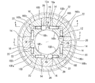
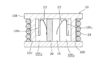
次に、図1ないし図5を参照して、本発明の第1の実施形態について説明する。なお、図1は本発明に係る双方向クラッチの側面図、図2は図1の2−2線に沿う断面図、図3は図2の3−3線に沿う断面図、図4は図2の4−4線に沿う断面図、図5は図2の要部拡大図である。 Next, a first embodiment of the present invention will be described with reference to FIGS. 1 is a side view of the bidirectional clutch according to the present invention, FIG. 2 is a sectional view taken along line 2-2 in FIG. 1, FIG. 3 is a sectional view taken along line 3-3 in FIG. 2 is a cross-sectional view taken along line 4-4 of FIG. 2, and FIG.
図1ないし図4に示すように、双方向クラッチはベース部材10を備え、このベース部材10は適当な金属材料又は樹脂材料で作られる。ベース部材10は環状の本体10Aを有し、本体10Aの軸方向外面にはその径方向に一対の突状部10B(図1及び図3参照)が形成されている。この突状部10Bは双方向クラッチを相手機構部材に回転不能に取り付けるための突起部である。
As shown in FIGS. 1 to 4, the bidirectional clutch includes a
図3に示すように、ベース部材本体10Aの中心部には軸部材12が回転自在に挿通される孔10Cが形成されている。図1に示すように、軸部材12の一方の端部側にはストッパピン12Aが貫通して設けられ、このストッパピン12Aによりベース部材本体10Aが軸部材12の該端部から脱落しないようにされている。
As shown in FIG. 3, a hole 10C through which the
図1及び図3に示すように、軸部材12の他端部には、例えば、横断面がD字形になるように、平坦面部12Bが形成され、この他端部は、当該平坦面部12Bによって、例えばノート型パーソナルコンピュータの蓋のヒンジ軸と一体回転自在に連結される。
As shown in FIGS. 1 and 3, the other end portion of the
図2に示すように、環状のベース部材10は、更に本体10Aの内面側から一体的に軸部材12と平行に立設されたリテーナ部10Dを有する。このリテーナ部10Dは扇形の横断面を有して3箇所以上に形成されて成り、図示の実施形態においては、4箇所に形成されている。これらの扇形リテーナ部10Dは、軸部材12の周方向に等間隔で配置され、各リテーナ部10Dは軸部材12の外周面に沿って延びる湾曲した内面10D1と、環状のベース部材本体10Aの外面に沿って延びる湾曲し外面10D2とを備える。各湾曲内面10D1は軸部材12の外周面を画成する円よりも幾分大きな同心円によって画成され、各湾曲外面10D2は環状のベース部材本体10Aの外周面を画成する円よりも小さな同心円によって画成される。
As shown in FIG. 2, the
図2に示すように、互いに隣接する2つのリテーナ部10D間には、軸部材12の径方向に延びるガイド通路14が形成され、各ガイド通路14の径方向内端の開口部には、軸部材12の外周面が露出している。
As shown in FIG. 2, a
図2及び図3に示すように、本発明に係る双方向クラッチは、また、各ガイド通路14に沿って径方向に摺動自在に収容された駒部材16を備える。各駒部材16の径方向内面は、軸部材12の径方向の面に対して直交する平坦面によって構成され、軸部材12の外周面と、左右両側のリテーナ部10Dの側面と協働して空間18を形成する。
駒部材16は高硬度の金属製とされ、この実施例においては、鉄系燒結材で形成されている。高硬度の金属としては、他に浸炭焼入鋼材等も使用可能である。また、駒部材16を構成する材料は金属に限られない。高硬度材料であれば、セラミック、あるいは樹脂であっても使用に耐え得る程度に硬度の高いものは採用可能である。
As shown in FIGS. 2 and 3, the bidirectional clutch according to the present invention further includes a
The
双方向クラッチは、更に、空間部18内に収容された転動部材としてのニードル20を備える。このニードル20の軸部材12の軸線方向の長さは、図3に示すように駒部材16の長さと実質的に同一である。
The bidirectional clutch further includes a
図5に詳しく図示するように、駒部材16の径方向内面は軸部材12の径方向の面に対して直交する平坦面によって構成されるのに対して軸部材12の外周面は真円の曲面なので、空間部18は、中央部に駒部材16の径方向内面と軸部材12の外周面との距離が最も狭い狭窄部18Aを有し、狭窄部18Aの両側に軸部材12の周囲方向に沿って逆テーパ状に拡開形成された拡開部18Bを有する。狭窄部18Aにおける、駒部材16の径方向内面と軸部材12の外周面との距離はニードル20の径よりも小さい。拡開部18Bにおける、駒部材16の径方向内面と軸部材12の外周面との距離はニードル20の径よりも大きい。
As shown in detail in FIG. 5, the inner surface in the radial direction of the
図4及び図5に示すように、互いに隣接する2つの扇形リテーナ部10Dの向かい合った側面、即ちガイド通路14を形成する側面には、該側面に対して垂直に穿設された溝部10D3(図4参照)が形成されている。また、図4に示すように、各溝部10D3内の奥にはベース部材本体10Aと一体に隔壁部10D4が形成されている。
As shown in FIG. 4 and FIG. 5, a
図2、図4及び図5に示すように、この各溝部10D3内の奥に形成された隔壁部10D4には、板ばね22が取り付けられている。各板ばね22は曲げ加工されて、その一端部は隔壁部10D4の自由端に装着され、他端部は各空間部18の狭窄部18B内に伸出するように曲げられ、空間部18B内に配置されニードル20を狭窄部18Aに向かって弾性的に付勢する手段(本発明における第2の付勢手段)として機能する。この板ばね22の存在により、ニードル20の軸部材12に対する制動動作の確実性を高めることができる。
As shown in FIGS. 2, 4, and 5, a
ニードル20に対する付勢手段は、板ばねに限らず、弾発力を発揮する素材であれば、当業界に現在知られている如何なるものも使用可能であることは勿論である。
The biasing means for the
図1ないし図5に示すように、双方向クラッチは、更に、4つの扇形リテーナ部10Dの外側湾曲面10D2の周囲に巻回装着されたコイルばね24を備える。このコイルばね24は4つの駒部材16を軸部材12に向かって弾性的に付勢する手段(本発明における第1の付勢手段)として機能する。
As shown in FIGS. 1 to 5, two-way clutch further comprises a
駒部材16に対する付勢手段は、コイルばねに限らず、リテーナ部10Dの外側湾曲面10D2の周囲に装着できて弾発力を発揮する素材であれば、当業界に現在知られている如何なるものも使用可能であることは勿論である。例えば、横断面C字形の略円筒形の板ばねでもよい。
Biasing means for the
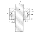
また、駒部材16に対する付勢手段は、各駒部材ごとに設けることも可能である。例えば、図8に示した如く、ベース部材10、扇形リテーナ部10D、後述する保持板26の周囲を囲むように円筒形のハウジング111を設け、該ハウジング111の内周面と個々の駒部材16の外面との間のそれぞれに、波状に屈曲させた板ばね124を設け、該板ばね124により、個々の駒部材16を軸部材12に向かって弾性的に付勢するようにしてもよい。いずれにしても、駒部材16に対する付勢手段は、当業界において公知の付勢手段の中から適宜選択することができる。
Further, the urging means for the
図1及び図3に示すように、双方向クラッチは、更に、駒部材16、ニードル部材20及びコイルばね24をベース部材本体10Aと協働して挟持し、かつ軸方向へ抜けないようにするための保持板26を備え、この保持板26は、着脱自在のEリング等の止め具28により所定位置に保持される。
As shown in FIGS. 1 and 3, the bidirectional clutch further clamps the
次に、図5を参照して以上で述べた双方向クラッチの動作について説明する。
以下の説明は、双方向クラッチの回転軸12がノート型パーソナルコンピュータの蓋のヒンジ軸と一体に回転するように結合されている場合について行なう。
Next, the operation of the bidirectional clutch described above will be described with reference to FIG.
In the following description, the
また、図5に示された状態においては、ノート型パーソナルコンピュータの蓋が閉鎖位置にあって、双方向クラッチのニードル20が図5に示す空間部18の一方(図5中左側)の拡開部18Bにあるものとする。
In the state shown in FIG. 5, the lid of the notebook personal computer is in the closed position, and the
図5において、蓋が閉鎖位置から矢印Aの方向に回動させられているとき、軸部材12も同じ方向に回動する。これに伴ないニードル20は図中時計方向に転動しつつ、板ばね22の付勢力に抗して、矢印Aと同方向即ち図中反時計方向に移動する。しかし、扇形リテーナ部10Dの側面により移動を妨げられ、二―ドル20の径より径方向の距離が大きい拡開部18B内で空転する。
In FIG. 5, when the lid is rotated from the closed position in the direction of arrow A, the
蓋が閉鎖位置から一定の開位置まで移動して蓋の開操作が停止すると、重力の作用により、蓋を閉鎖位置方向に戻そうとする力が軸部材12に作用する。このとき、軸部材12は図5の矢印Aと反対方向に回動し、これに伴ないニードル20は図中反時計方向に転動しつつ、矢印Aと反対の方向に狭窄部18Aまで移動する。狭窄部18Aでは、軸部材12の外周面と駒部材16の径方向内面との間の距離がニードルの径よりも小さいため、ニードル20は軸部材12の回転に伴なって転動しつつ狭窄部に楔のように食い込み、軸部材12に制動力を付与する。これにより、蓋は開操作が停止した開位置に保持される。
When the lid is moved from the closed position to a certain open position and the opening operation of the lid is stopped, a force for returning the lid toward the closed position acts on the
次に、蓋を閉じるときは、蓋を所定以上の力で押し下げる操作が必要になる。この力は、駒部材16の径方向外方への移動を許容するコイルばね24の弾発力に依存して決まり、その弾発力以上の力である。このとき、軸部材12に対して図5の矢印Aと反対方向に作用するトルクが、コイルばね24の弾性力により定まる所定値以上になると、ニードル20は、コイルばね24の弾性力に抗して狭窄部18Aを押し広げ、駒部材16を軸部材12の径方向外方に移動させる。駒部材16が外方に移動すると、ニードル20は狭窄部18Aを超えた反対側(図5中右側)の拡開部18Bに移動する。この図5中右側の拡開部18Bでは、二―ドルの動きに対する抵抗は生じないため、蓋は閉鎖位置まですんなり戻ることができる。
Next, when closing the lid, it is necessary to push down the lid with a predetermined force or more. This force is determined depending on the elastic force of the
次に、図2に対応する図6を参照して、本発明に係る双方向クラッチの第2の実施形態について説明する。 Next, a second embodiment of the bidirectional clutch according to the present invention will be described with reference to FIG. 6 corresponding to FIG.
第2の実施形態は、駒部材16の構成に関する変更点を除けば第1の実施形態と同じものである。即ち、第2の実施形態では、駒部材16Aは低硬度の樹脂材料で形成されている。低硬度駒部材16Aの径方向内面とニードル20との間には高硬度材料で形成された板部材16Bが介設される。この板部材16Bは、高硬度材料、例えば鉄系燒結金属材で構成されることが好ましい。浸炭焼入鋼材を用いることも可能である。また、セラミックや、硬度が必要以上に高ければ樹脂材料を使用することも可能である。
The second embodiment is the same as the first embodiment except for the changes relating to the configuration of the
また、この第2の実施形態において、駒部材を、低硬度の樹脂材料から形成された低硬度部16Aと、この低硬度部16Aの径方向内面側に高硬度材料で形成された高硬度部16Bとから成る複合体として一体に構成してもよい。
Further, in the second embodiment, the piece member includes a
以上で述べた第1及び第2の実施形態において、ニードル20が軸部材12の回動に伴なって転動して狭窄部18Aに偏倚することが確実に保証される場合には、ニードル付勢手段即ち板ばね22については省いてもよい。
In the first and second embodiments described above, when it is ensured that the
また、以上で述べた第1及び第2の実施形態においては、ベース部材本体10Aの内面側を、十字方向に延びるガイド通路14で四分割するように扇形リテーナ部10Dを4つ設け、各ガイド通路14に一つずつ計4つの駒部材16を使用した。しかし、扇形リテーナ部10D、ガイド通路14、駒部材16の数はこれに限られるものではない。それぞれ3つ以上の複数であれば双方向クラッチの安定した動作を得ることができる。ただ、それらは軸部材12の回りに等間隔に配置することが好ましい。
Further, in the first and second embodiments described above, four fan-shaped
また、以上では、第1及び第2の実施形態について、双方向クラッチの回転軸12がノート型パーソナルコンピュータの蓋のヒンジ軸と一体に回転するように結合されている場合について説明したが、双方向クラッチのベース部材10がノート型パーソナルコンピュータの蓋のヒンジ軸と一体に回転するように結合されている場合も実質的に同様であることは理解できるであろう。
In the above description, the first and second embodiments have been described with respect to the case where the
次に、図7を参照して、本発明に係る双方向クラッチの第3の実施形態について説明する。
第3の実施形態は、転動部材に関する変更点を除けば図3に示された実施形態と同じものである。即ち、第3の実施形態では、転動部材120は、図3の実施形態におけるニードルに代えて、軸方向に配列した複数の、図示例では2個の、ボールで構成されている。この実施形態を採用することにより製造コストをより抑えることができる利点がある。
Next, a third embodiment of the bidirectional clutch according to the present invention will be described with reference to FIG.
The third embodiment is the same as the embodiment shown in FIG. 3 except for the changes relating to the rolling members. That is, in the third embodiment, the rolling
10:ベース部材
10A:ベース部材本体
10B:突状部
10C:孔
10D:扇形リテーナ部
10D1:内側湾曲面
10D2:外側湾曲面
10D3:溝部
10D4:隔壁部
12:軸部材
12A:ストッパピン
12B:平坦面部
14:ガイド通路
16:駒部材
18:空間部
18A:狭窄部
18B:拡開部
20:ニードル
22:板ばね(ニードル付勢手段)
24:コイルばね(駒部材付勢手段)
26:保持板
28:保持リング
10:
24: Coil spring (piece member biasing means)
26: Retaining plate 28: Retaining ring
Claims (8)
該ベース部材に立設され、軸部材の周方向に間隔を開けて配置された複数のリテーナ部材と、
該複数のリテーナ部材間に配設され、軸部材の外周面との間に所定の距離をおいて、かつ軸部材の径方向に移動自在に配置された駒部材と、
これらの軸部材、リテーナ部材および駒部材により形成される空間部と、
該空間部に挿入された転動部材と、
前記空間部における、軸部材の周方向中央の、軸部材と駒部材との距離が転動部材の径よりも小さい狭窄部と、該狭窄部の両側に逆テーパ状に拡開形成された軸部材と駒部材との距離が転動部材の径よりも大きい拡開部と、
前記駒部材を軸部材方向に付勢する第1の付勢手段とを備えることを特徴とする、双方向クラッチ。 A base member the shaft member is threaded relatively rotatably inserted,
A plurality of retainer members which are erected on the base member and arranged at intervals in the circumferential direction of the shaft member;
A piece member disposed between the plurality of retainer members, disposed at a predetermined distance from the outer peripheral surface of the shaft member, and movable in the radial direction of the shaft member;
A space formed by these shaft members, retainer members and piece members;
A rolling member inserted into the space,
In the space portion, in the center in the circumferential direction of the shaft member, a narrowed portion in which the distance between the shaft member and the piece member is smaller than the diameter of the rolling member , and a shaft that is widened in an inversely tapered manner on both sides of the narrowed portion An expanded portion in which the distance between the member and the piece member is larger than the diameter of the rolling member ;
And a first urging means for urging the piece member in the axial member direction.
The said 1st biasing means is comprised by the substantially cylindrical leaf | plate spring of the cross-sectional C shape provided in the circumference | surroundings of the said retainer, The one of Claims 1 thru | or 6 characterized by the above-mentioned. Bi-directional clutch.
Priority Applications (2)
| Application Number | Priority Date | Filing Date | Title |
|---|---|---|---|
| JP2007035277A JP4281069B2 (en) | 2007-02-15 | 2007-02-15 | Two-way clutch |
| CN2007101675979A CN101245819B (en) | 2007-02-15 | 2007-10-29 | Bi-direction clutch |
Applications Claiming Priority (1)
| Application Number | Priority Date | Filing Date | Title |
|---|---|---|---|
| JP2007035277A JP4281069B2 (en) | 2007-02-15 | 2007-02-15 | Two-way clutch |
Publications (3)
| Publication Number | Publication Date |
|---|---|
| JP2008196667A JP2008196667A (en) | 2008-08-28 |
| JP2008196667A5 JP2008196667A5 (en) | 2008-10-09 |
| JP4281069B2 true JP4281069B2 (en) | 2009-06-17 |
Family
ID=39755794
Family Applications (1)
| Application Number | Title | Priority Date | Filing Date |
|---|---|---|---|
| JP2007035277A Active JP4281069B2 (en) | 2007-02-15 | 2007-02-15 | Two-way clutch |
Country Status (2)
| Country | Link |
|---|---|
| JP (1) | JP4281069B2 (en) |
| CN (1) | CN101245819B (en) |
Cited By (2)
| Publication number | Priority date | Publication date | Assignee | Title |
|---|---|---|---|---|
| US20220195798A1 (en) * | 2017-09-06 | 2022-06-23 | Tok, Inc. | Opening/closing direction restriction mechanism for manual shutter device and opening/closing direction restriction mechanism for suspended sliding door |
| US11993983B2 (en) * | 2022-03-13 | 2024-05-28 | Tok, Inc. | Restriction mechanism for suspended sliding door device |
Family Cites Families (3)
| Publication number | Priority date | Publication date | Assignee | Title |
|---|---|---|---|---|
| CN2077930U (en) * | 1990-05-10 | 1991-05-29 | 北京顺义潮白河节能器械制造厂 | Double-directioned overstep clutch of ratchet type |
| JP2880296B2 (en) * | 1990-12-17 | 1999-04-05 | 不二精器株式会社 | Bidirectional locking clutch |
| JP2003240021A (en) * | 2002-02-19 | 2003-08-27 | Ntn Corp | Rotation transmitting device |
-
2007
- 2007-02-15 JP JP2007035277A patent/JP4281069B2/en active Active
- 2007-10-29 CN CN2007101675979A patent/CN101245819B/en not_active Expired - Fee Related
Cited By (3)
| Publication number | Priority date | Publication date | Assignee | Title |
|---|---|---|---|---|
| US20220195798A1 (en) * | 2017-09-06 | 2022-06-23 | Tok, Inc. | Opening/closing direction restriction mechanism for manual shutter device and opening/closing direction restriction mechanism for suspended sliding door |
| US11512531B2 (en) * | 2017-09-06 | 2022-11-29 | Tok, Inc. | Restriction mechanism for manual shutter device |
| US11993983B2 (en) * | 2022-03-13 | 2024-05-28 | Tok, Inc. | Restriction mechanism for suspended sliding door device |
Also Published As
| Publication number | Publication date |
|---|---|
| CN101245819B (en) | 2011-06-08 |
| CN101245819A (en) | 2008-08-20 |
| JP2008196667A (en) | 2008-08-28 |
Similar Documents
| Publication | Publication Date | Title |
|---|---|---|
| JP5076780B2 (en) | Vehicle seat reclining device | |
| JP2005207465A (en) | Two axis hinge apparatus | |
| JP2002295446A (en) | Hinge device | |
| US20090205170A1 (en) | Hinge Assembly | |
| JPWO2008001951A1 (en) | HINGE DEVICE AND ELECTRONIC DEVICE USING HINGE DEVICE | |
| TW202122692A (en) | Dual-shaft hinge capable of being alternately rotated (II) capable of enhancing structural strength and reducing production cost by resulting convenient production and reducing manufacturing procedures and parts | |
| JP2010255837A (en) | Clutch device and seat device | |
| US20110047754A1 (en) | Hinge device and apparatus using hinge device | |
| JP4734283B2 (en) | Door hinge with vehicle check function | |
| JP4281069B2 (en) | Two-way clutch | |
| JP2008020033A (en) | Tilt hinge and electronic equipment | |
| JPWO2005095821A1 (en) | Rotary damper | |
| JP2013050117A (en) | Rotary damper | |
| JP2012007635A (en) | Rotating inertial mass damper | |
| JP2004360441A (en) | Hinge structure | |
| JP2002227825A (en) | Hinge device of portable equipment | |
| JP2016142005A (en) | Door handle unit | |
| JP2002005152A (en) | Tilting hinge | |
| JP4021175B2 (en) | Hinge device | |
| JP2006046382A (en) | Hinge device | |
| JP2012117563A (en) | Mechanism for restricting movement in one direction | |
| CN209800640U (en) | Cold air damper | |
| JP3979966B2 (en) | Door hinge unit | |
| JP2009156466A5 (en) | ||
| JP2005054971A (en) | Hinge unit |
Legal Events
| Date | Code | Title | Description |
|---|---|---|---|
| A521 | Request for written amendment filed |
Free format text: JAPANESE INTERMEDIATE CODE: A523 Effective date: 20080724 |
|
| A621 | Written request for application examination |
Free format text: JAPANESE INTERMEDIATE CODE: A621 Effective date: 20080724 |
|
| A521 | Request for written amendment filed |
Free format text: JAPANESE INTERMEDIATE CODE: A523 Effective date: 20080818 |
|
| A977 | Report on retrieval |
Free format text: JAPANESE INTERMEDIATE CODE: A971007 Effective date: 20090128 |
|
| TRDD | Decision of grant or rejection written | ||
| A01 | Written decision to grant a patent or to grant a registration (utility model) |
Free format text: JAPANESE INTERMEDIATE CODE: A01 Effective date: 20090203 |
|
| A01 | Written decision to grant a patent or to grant a registration (utility model) |
Free format text: JAPANESE INTERMEDIATE CODE: A01 |
|
| A61 | First payment of annual fees (during grant procedure) |
Free format text: JAPANESE INTERMEDIATE CODE: A61 Effective date: 20090305 |
|
| R150 | Certificate of patent or registration of utility model |
Ref document number: 4281069 Country of ref document: JP Free format text: JAPANESE INTERMEDIATE CODE: R150 Free format text: JAPANESE INTERMEDIATE CODE: R150 |
|
| FPAY | Renewal fee payment (event date is renewal date of database) |
Free format text: PAYMENT UNTIL: 20120327 Year of fee payment: 3 |
|
| FPAY | Renewal fee payment (event date is renewal date of database) |
Free format text: PAYMENT UNTIL: 20130327 Year of fee payment: 4 |
|
| R250 | Receipt of annual fees |
Free format text: JAPANESE INTERMEDIATE CODE: R250 |
|
| FPAY | Renewal fee payment (event date is renewal date of database) |
Free format text: PAYMENT UNTIL: 20140327 Year of fee payment: 5 |
|
| R250 | Receipt of annual fees |
Free format text: JAPANESE INTERMEDIATE CODE: R250 |
|
| R250 | Receipt of annual fees |
Free format text: JAPANESE INTERMEDIATE CODE: R250 |
|
| R250 | Receipt of annual fees |
Free format text: JAPANESE INTERMEDIATE CODE: R250 |
|
| R250 | Receipt of annual fees |
Free format text: JAPANESE INTERMEDIATE CODE: R250 |
|
| R250 | Receipt of annual fees |
Free format text: JAPANESE INTERMEDIATE CODE: R250 |
|
| S533 | Written request for registration of change of name |
Free format text: JAPANESE INTERMEDIATE CODE: R313533 |
|
| R350 | Written notification of registration of transfer |
Free format text: JAPANESE INTERMEDIATE CODE: R350 |
|
| R250 | Receipt of annual fees |
Free format text: JAPANESE INTERMEDIATE CODE: R250 |
|
| S531 | Written request for registration of change of domicile |
Free format text: JAPANESE INTERMEDIATE CODE: R313531 |
|
| R350 | Written notification of registration of transfer |
Free format text: JAPANESE INTERMEDIATE CODE: R350 |
|
| R250 | Receipt of annual fees |
Free format text: JAPANESE INTERMEDIATE CODE: R250 |
|
| R250 | Receipt of annual fees |
Free format text: JAPANESE INTERMEDIATE CODE: R250 |
|
| R250 | Receipt of annual fees |
Free format text: JAPANESE INTERMEDIATE CODE: R250 |
|
| R250 | Receipt of annual fees |
Free format text: JAPANESE INTERMEDIATE CODE: R250 |
|
| R250 | Receipt of annual fees |
Free format text: JAPANESE INTERMEDIATE CODE: R250 |
|
| R250 | Receipt of annual fees |
Free format text: JAPANESE INTERMEDIATE CODE: R250 |