JP4280320B2 - Vibration damping device for rotor supported by magnetic bearing mechanism - Google Patents
Vibration damping device for rotor supported by magnetic bearing mechanism Download PDFInfo
- Publication number
- JP4280320B2 JP4280320B2 JP07412598A JP7412598A JP4280320B2 JP 4280320 B2 JP4280320 B2 JP 4280320B2 JP 07412598 A JP07412598 A JP 07412598A JP 7412598 A JP7412598 A JP 7412598A JP 4280320 B2 JP4280320 B2 JP 4280320B2
- Authority
- JP
- Japan
- Prior art keywords
- vibration damping
- dome
- spheres
- magnetic bearing
- shaped recess
- Prior art date
- Legal status (The legal status is an assumption and is not a legal conclusion. Google has not performed a legal analysis and makes no representation as to the accuracy of the status listed.)
- Expired - Fee Related
Links
- 238000013016 damping Methods 0.000 title claims description 44
- 230000007246 mechanism Effects 0.000 title claims description 21
- 239000000463 material Substances 0.000 claims description 7
- 239000007769 metal material Substances 0.000 claims description 5
- 230000005489 elastic deformation Effects 0.000 claims description 3
- 238000006073 displacement reaction Methods 0.000 description 7
- 230000002238 attenuated effect Effects 0.000 description 2
- 230000002411 adverse Effects 0.000 description 1
- 239000000470 constituent Substances 0.000 description 1
- 230000007423 decrease Effects 0.000 description 1
- 238000010586 diagram Methods 0.000 description 1
- 230000000694 effects Effects 0.000 description 1
- 239000007788 liquid Substances 0.000 description 1
- 238000004519 manufacturing process Methods 0.000 description 1
- 238000005096 rolling process Methods 0.000 description 1
- 238000007789 sealing Methods 0.000 description 1
Images

Classifications
-
- F—MECHANICAL ENGINEERING; LIGHTING; HEATING; WEAPONS; BLASTING
- F16—ENGINEERING ELEMENTS AND UNITS; GENERAL MEASURES FOR PRODUCING AND MAINTAINING EFFECTIVE FUNCTIONING OF MACHINES OR INSTALLATIONS; THERMAL INSULATION IN GENERAL
- F16C—SHAFTS; FLEXIBLE SHAFTS; ELEMENTS OR CRANKSHAFT MECHANISMS; ROTARY BODIES OTHER THAN GEARING ELEMENTS; BEARINGS
- F16C32/00—Bearings not otherwise provided for
- F16C32/04—Bearings not otherwise provided for using magnetic or electric supporting means
- F16C32/0406—Magnetic bearings
- F16C32/044—Active magnetic bearings
- F16C32/0474—Active magnetic bearings for rotary movement
- F16C32/0476—Active magnetic bearings for rotary movement with active support of one degree of freedom, e.g. axial magnetic bearings
-
- F—MECHANICAL ENGINEERING; LIGHTING; HEATING; WEAPONS; BLASTING
- F04—POSITIVE - DISPLACEMENT MACHINES FOR LIQUIDS; PUMPS FOR LIQUIDS OR ELASTIC FLUIDS
- F04D—NON-POSITIVE-DISPLACEMENT PUMPS
- F04D19/00—Axial-flow pumps
- F04D19/02—Multi-stage pumps
- F04D19/04—Multi-stage pumps specially adapted to the production of a high vacuum, e.g. molecular pumps
- F04D19/048—Multi-stage pumps specially adapted to the production of a high vacuum, e.g. molecular pumps comprising magnetic bearings
-
- F—MECHANICAL ENGINEERING; LIGHTING; HEATING; WEAPONS; BLASTING
- F04—POSITIVE - DISPLACEMENT MACHINES FOR LIQUIDS; PUMPS FOR LIQUIDS OR ELASTIC FLUIDS
- F04D—NON-POSITIVE-DISPLACEMENT PUMPS
- F04D29/00—Details, component parts, or accessories
- F04D29/66—Combating cavitation, whirls, noise, vibration or the like; Balancing
- F04D29/661—Combating cavitation, whirls, noise, vibration or the like; Balancing especially adapted for elastic fluid pumps
- F04D29/668—Combating cavitation, whirls, noise, vibration or the like; Balancing especially adapted for elastic fluid pumps damping or preventing mechanical vibrations
-
- F—MECHANICAL ENGINEERING; LIGHTING; HEATING; WEAPONS; BLASTING
- F16—ENGINEERING ELEMENTS AND UNITS; GENERAL MEASURES FOR PRODUCING AND MAINTAINING EFFECTIVE FUNCTIONING OF MACHINES OR INSTALLATIONS; THERMAL INSULATION IN GENERAL
- F16C—SHAFTS; FLEXIBLE SHAFTS; ELEMENTS OR CRANKSHAFT MECHANISMS; ROTARY BODIES OTHER THAN GEARING ELEMENTS; BEARINGS
- F16C27/00—Elastic or yielding bearings or bearing supports, for exclusively rotary movement
-
- F—MECHANICAL ENGINEERING; LIGHTING; HEATING; WEAPONS; BLASTING
- F16—ENGINEERING ELEMENTS AND UNITS; GENERAL MEASURES FOR PRODUCING AND MAINTAINING EFFECTIVE FUNCTIONING OF MACHINES OR INSTALLATIONS; THERMAL INSULATION IN GENERAL
- F16C—SHAFTS; FLEXIBLE SHAFTS; ELEMENTS OR CRANKSHAFT MECHANISMS; ROTARY BODIES OTHER THAN GEARING ELEMENTS; BEARINGS
- F16C32/00—Bearings not otherwise provided for
- F16C32/04—Bearings not otherwise provided for using magnetic or electric supporting means
- F16C32/0406—Magnetic bearings
- F16C32/0408—Passive magnetic bearings
- F16C32/0423—Passive magnetic bearings with permanent magnets on both parts repelling each other
- F16C32/0425—Passive magnetic bearings with permanent magnets on both parts repelling each other for radial load mainly
-
- F—MECHANICAL ENGINEERING; LIGHTING; HEATING; WEAPONS; BLASTING
- F16—ENGINEERING ELEMENTS AND UNITS; GENERAL MEASURES FOR PRODUCING AND MAINTAINING EFFECTIVE FUNCTIONING OF MACHINES OR INSTALLATIONS; THERMAL INSULATION IN GENERAL
- F16C—SHAFTS; FLEXIBLE SHAFTS; ELEMENTS OR CRANKSHAFT MECHANISMS; ROTARY BODIES OTHER THAN GEARING ELEMENTS; BEARINGS
- F16C2360/00—Engines or pumps
- F16C2360/44—Centrifugal pumps
- F16C2360/45—Turbo-molecular pumps
Landscapes
- Engineering & Computer Science (AREA)
- General Engineering & Computer Science (AREA)
- Mechanical Engineering (AREA)
- Magnetic Bearings And Hydrostatic Bearings (AREA)
- Support Of The Bearing (AREA)
- Vibration Prevention Devices (AREA)
Description
【0001】
【発明の属する技術分野】
本発明は、磁気軸受機構で支持されたロータの振動減衰装置であって、前記磁気軸受機構が少なくとも1個のラジアル磁気軸受を含んでおり該ラジアル磁気軸受のステータ側部材が中間部材に固定連結されている振動減衰装置に関する。
【0002】
【従来の技術】
高速で回転するロータを支持するための無接触式の軸受機構として、これまでに様々な形式の電子制御式ないし機械補助式の磁気軸受機構が提案されている。一般的に、それら磁気軸受機構には軸方向及び径方向の振動が発生する。特にロータの回転速度が上昇または低下して行くときには、そのロータが共振状態になる回転速度を通過する際に、いわゆる危険回転数状態となることがある。ロータが磁気軸受機構で支持されており、しかも、例えばターボ分子ポンプのように、ロータと周囲の部材との間の隙間寸法を、非常に小さな寸法に保持しなければならない場合には、上述した危険回転数状態においてロータがステータ側部材をこすってしまうことがあり、ついには装置が損傷することもある。従って、磁気軸受機構には、適当な振動減衰部材を装備して、安定した静かな回転が確実に得られるようにすることが重要である。
【0003】
【発明が解決しようとする課題】
磁気軸受機構で支持されたロータの振動減衰のための様々な方式がこれまでに提案されている。特に本発明が関係しているのは、磁気軸受機構がラジアル磁気軸受を含んでいる場合である。ラジアル磁気軸受では、渦電流の関与が小さいため、強力な振動減衰性能が得られない。またこの場合に、中間部材を介してロータに対して振動減衰作用を及ぼすようにした振動減衰装置が特に有効であることが明らかとなっている。ドイツ特許公開公報第DE−AS2658925号、及びPollermannの著作である”Bauelement der physikalischen Technik”、Spinger−Verlag社刊(1955年)の第97〜第98頁に、中間部材を介してロータに対して振動減衰作用を及ぼすようにした機械的な振動減衰部材が示されている。ただし、それらに示されている振動減衰部材は、軸方向には固定されていない。従って、軸方向の隙間寸法をできるだけ小さな寸法に保持することが必要とされているロータには、それらの振動減衰部材は適していない。ロータの振動減衰のためのその他の従来の振動減衰装置として、比較的大きな質量の中間部材を必要とする装置があるが、質量の大きな中間部材は振動減衰特性に悪影響を及ぼす。更に別の振動減衰装置として、液体封入構造を備えた機械的な振動減衰装置も公知となっている。しかしながらそのような装置は、振動減衰性能が不十分で動作の信頼性が低いため、適用分野が限られている。また、更に複雑な構造の振動減衰装置として、例えばドイツ特許公告公報DE−OS3239328号に示されている種類の装置があるが、その種の装置は、中間部材をセンタリングするために高コストのセンタリング機構が必要であるため、上述の課題を解決するための好適な構成とはいえない。
【0004】
本発明は、磁気軸受機構で支持されたロータの振動減衰装置であって、以上に述べた不都合を生じることのない振動減衰装置を提供することを目的とするものである。また特に、本発明が提供する振動減衰装置は、中間部材を介して振動減衰を行うようにした機械的な振動減衰装置を改良したものである。中間部材は、軸方向には固定され、径方向には移動可能なものである。また、本発明が提供する振動減衰装置は、複雑な構造を必要とせず、寸法及び体積を小さく抑えることができ、しかも、簡明な構造でセンタリング機能が得られるものである。また、振動減衰のための機構を別途付加する必要もない。
【0005】
【課題を解決するための手段】
上記目的は、請求項1ないし請求項2の特徴部分に記載した構成要件によって達成される。また、請求項3から請求項6は、本発明の実施の形態にかかる具体的な構成を記載したものである。
【0006】
中間部材を複数の球体の上に載置して支持し、更にそれら球体を、ハウジング側部材及び中間部材に設けたドーム形凹部の中に配設することで、ロータを軸方向には固定し、ロータの径方向の変位に対しては振動減衰がなされるようにしている。軸方向の荷重を支持するこの支持構造は、球体が径方向に変位したときには適切な軸方向の力が作用して、球体をドーム形凹部の中でセンタリングさせるように機能する。これによって、中間部材の構成を簡明なものとすることが可能となっている。また、中間部材を複数の球体の上に直接載置することでセンタリング機能を得ているため、センタリングに関する調整が不要となっている。ドーム形凹部の表面の形状は球面形状としてもよく、そうすれば製作が容易となる。ただし、ドーム形凹部の表面の形状はこれに限られず、必要とされる最大荷重や振動減衰性能の条件に応じてその他の任意の表面形状とすることができる。
【0007】
本発明の特に優れた点は、荷重支持機能を有する部材に振動減衰機能を直接組み込んだ構成としたことにある。1つの実施の形態では、複数の球体を弾性変形し易い材料で形成することで、それら球体が、それらの配設位置において、振動に伴うエネルギを吸収するようにしており、それによって、それら球体が振動減衰機能を提供するようにしている。尚、この場合には、それら球体に作用する応力の大きさが、それら球体の材料の弾性変形領域内にあるようにすることが重要である。また、軸方向剛性が径方向剛性より大きくなければならないが、十分に多くの個数の球体を用いることでそうすることができる。更に、十分に多くの個数の球体を用いることで、各球体に作用する面応力を低く抑えることができ、ひいては転がり抵抗を小さく抑えることができる。付加的な振動減衰部材を装備することは必ずしも必要ではないが、作動条件が特に厳しい場合には、それを装備するようにしてもよい。中間部材及びそれを支持する構造に関する別の実施の形態として、ドーム形凹部の表面を弾性変形し易い材料で形成するようにしてもよい。この場合には、球体を金属材料で形成することができる。
【0008】
【発明の実施の形態】
以下に図1〜図3を参照しつつ、本発明をその実施の形態に即して更に詳細に説明して行く。
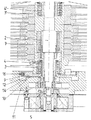
図1は、本発明をターボ分子ポンプに適用した場合の具体例を示したものである。この具体例に示した実施の形態では、単軸アクティブ制御方式(1つの軸方向にのみアクティブ制御を行う方式)の磁気軸受機構によってロータ2が支持されており、この磁気軸受機構は、パッシブ形ラジアル磁気軸受とアクティブ形アキシャル磁気軸受とで構成されている。パッシブ形ラジアル磁気軸受は2個の軸受部から成り、それら軸受部は、各々が、ロータ側磁石アセンブリ3、3’とステータ側磁石アセンブリ4、4’とで構成されている。アクティブ形アキシャル磁気軸受は、図中に電磁石コイル5の記号で表した。参照番号7は駆動機構を示すものである。
【0009】
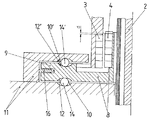
ロータ2は、ハウジングに対して固定された部材であるハウジング側部材11に対して相対的に振動するため、その振動を、中間部材8を介して減衰させるようにしている。中間部材8は、下側のパッシブ形ラジアル磁気軸受のステータ側磁石部材4と、支持板部9とで構成されている。中間部材8は、下側のパッシブ形ラジアル磁気軸受のステータ側磁石部材4とロータ側磁石部材3とを介してロータ2に接続されている。更に、この中間部材8とハウジング側部材11との間が、複数の球体14を介して接続されている。それら球体14の各々は、ハウジング側部材11に設けられたドーム形凹部10及び中間部材8の支持板部9に設けられたドーム形凹部12の中に配設されている。それら球体14は、本発明のこの実施の形態では、その弾性係数が金属材料の弾性係数より小さく弾性変形し易い材料で形成されており、従って、荷重支持機能を有する部材に振動減衰機能を直接組み込んだ構成となっている。また、別の実施の形態として、ドーム形凹部の表面を弾性変形し易い材料で形成するようにしてもよく、そうした場合には球体14を金属材料で形成することができる。また、図1及び図2に示したように、振動減衰部材16を介して中間部材8をハウジング側部材11に接続するようにしてもよい。
【0010】
ロータ側磁石部材3とステータ側磁石部材4との間には、図2に大きさdで示したように相対変位が発生し、この相対変位によって、中間部材8の支持板部9に軸方向の力が伝達される。そのため、中間部材8の支持板部9が球体14を押圧し、更にハウジング側部材11を押圧することになる。ロータ2の軸方向位置は、電磁石5の磁力制御によって目標位置に保持される。一方、ロータ2の径方向位置が目標位置から変位したならば、下側のパッシブ形ラジアル磁気軸受のロータ側磁石部材3及びステータ側磁石部材4を介してロータ2と中間部材8とが接続されているため、ロータ2と共に中間部材8も径方向に変位する。そして、中間部材8が複数の球体14の上に載置されて支持されており、それら球体14がハウジング側部材11及び中間部材8に夫々に形成されたドーム形凹部10及び12の中に配設されているため、センタ位置から径方向への変位が生じたときには復帰力が発生する。この復帰力の大きさは、球体14の半径とドーム形凹部10、12の半径との差、並びにその径方向への変位の大きさにも応じたものとなる。ロータ2を軸方向の両方向に固定したい場合には、図3に示したように、中間部材8の、球体14とは反対側にも、球体14’とドーム形凹部12’及び10’とから成る、上述の構造と同様の構造を備えるようにすればよい。またこの場合も、付加的な振動減衰部材16を用いて中間部材8の径方向の運動に対する振動減衰を行わせるようにしてもよい。パッシブ形ラジアル磁気軸受3、4を介して中間部材8とロータ2とが接続されているため、以上によってロータ2の径方向の運動に対する振動減衰がなされる。変位が小さい場合には、中間部材8の軸方向の運動の大きさは、径方向の変位の大きさと比べて更に小さく、無視し得る程度のものとなる。また、そのためには、軸方向剛性が径方向剛性より大きくなければならないが、十分に多くの個数の球体14を使用することで軸方向剛性を径方向剛性より大きくすることができる。
【0011】
【発明の効果】
以上の説明から明らかなように、本発明によれば、磁気軸受機構で支持されたロータの振動減衰装置として、コンパクトな構成で、動作信頼性が高く、高性能の振動減衰装置が得られる。
【図面の簡単な説明】
【図1】本発明にかかる構成の1つの実施の形態であって、ターボ分子ポンプに適用した具体例を示した図である。
【図2】図1のうちの本発明にかかる構成の部分を拡大して示した図である。
【図3】本発明にかかる構成の別の実施の形態であって、中間部材の両側に球体及びドーム形凹部を設けた具体例を示した図である。
【符号の説明】
2 ロータ
3 ロータ側磁石部材
4 ステータ側磁石部材
11 ハウジング側部材
10、10’ ドーム形凹部
12、12’ ドーム形凹部
14、14’ 球体
16 付加的な振動減衰部材[0001]
BACKGROUND OF THE INVENTION
The present invention relates to a vibration damping device for a rotor supported by a magnetic bearing mechanism, wherein the magnetic bearing mechanism includes at least one radial magnetic bearing, and a stator side member of the radial magnetic bearing is fixedly connected to an intermediate member. The present invention relates to a vibration damping device.
[0002]
[Prior art]
Various types of electronically controlled or mechanically assisted magnetic bearing mechanisms have been proposed as contactless bearing mechanisms for supporting a rotor that rotates at high speed. Generally, these magnetic bearing mechanisms generate vibrations in the axial direction and the radial direction. In particular, when the rotational speed of the rotor increases or decreases, a so-called dangerous rotational speed state may occur when passing through the rotational speed at which the rotor is in a resonance state. If the rotor is supported by a magnetic bearing mechanism, and the gap between the rotor and surrounding members must be kept very small, such as a turbomolecular pump, for example, as described above. In a critical rotational speed state, the rotor may rub the stator side member, and eventually the device may be damaged. Therefore, it is important to equip the magnetic bearing mechanism with an appropriate vibration damping member to ensure stable and quiet rotation.
[0003]
[Problems to be solved by the invention]
Various schemes for vibration damping of a rotor supported by a magnetic bearing mechanism have been proposed so far. The present invention is particularly relevant when the magnetic bearing mechanism includes a radial magnetic bearing. In radial magnetic bearings, strong vibration damping performance cannot be obtained because of the small involvement of eddy currents. Further, in this case, it has become clear that a vibration damping device that exerts a vibration damping action on the rotor via the intermediate member is particularly effective. German Patent Publication DE-AS 2658925 and “The Bauerment der Physikalischen Technic”, published by Pollermann, pages 97-98 of the company Spinger-Verlag (1955), to the rotor via an intermediate member A mechanical vibration damping member adapted to exert a vibration damping action is shown. However, the vibration damping member shown in them is not fixed in the axial direction. Therefore, those vibration damping members are not suitable for a rotor that is required to keep the axial gap dimension as small as possible. As another conventional vibration damping device for vibration damping of a rotor, there is a device that requires an intermediate member having a relatively large mass, but the intermediate member having a large mass adversely affects the vibration damping characteristics. As another vibration damping device, a mechanical vibration damping device having a liquid sealing structure is also known. However, such devices have limited application fields due to insufficient vibration damping performance and low operational reliability. Further, as a vibration damping device having a more complicated structure, for example, there is a device of the type shown in German Patent Publication DE-OS 3239328. This type of device is a high-cost centering device for centering an intermediate member. Since a mechanism is required, it cannot be said to be a suitable configuration for solving the above-described problem.
[0004]
An object of the present invention is to provide a vibration damping device for a rotor supported by a magnetic bearing mechanism, which does not cause the above-described disadvantages. In particular, the vibration damping device provided by the present invention is an improvement over a mechanical vibration damping device that performs vibration damping via an intermediate member. The intermediate member is fixed in the axial direction and movable in the radial direction. In addition, the vibration damping device provided by the present invention does not require a complicated structure, can be reduced in size and volume, and can obtain a centering function with a simple structure. Further, it is not necessary to add a mechanism for vibration damping.
[0005]
[Means for Solving the Problems]
The above object can be achieved by the constituent features described in the characterizing portions of
[0006]
The intermediate member is placed on and supported on a plurality of spheres, and the spheres are arranged in dome-shaped recesses provided in the housing side member and the intermediate member, thereby fixing the rotor in the axial direction. The vibration is attenuated with respect to the radial displacement of the rotor. This support structure for supporting an axial load functions so that when the sphere is displaced in the radial direction, an appropriate axial force acts to center the sphere in the dome-shaped recess. Thereby, the configuration of the intermediate member can be simplified. In addition, since the centering function is obtained by directly placing the intermediate member on the plurality of spheres, adjustment for centering is not necessary. The shape of the surface of the dome-shaped recess may be a spherical shape, which makes it easy to manufacture. However, the shape of the surface of the dome-shaped recess is not limited to this, and may be any other surface shape depending on the required maximum load and vibration damping performance conditions.
[0007]
A particularly excellent point of the present invention resides in that a vibration damping function is directly incorporated into a member having a load support function. In one embodiment, the plurality of spheres are formed of a material that is easily elastically deformed so that the spheres absorb energy associated with vibrations at the positions of the spheres. Provides a vibration damping function. In this case, it is important that the magnitude of the stress acting on the spheres is within the elastic deformation region of the material of the spheres. Also, the axial stiffness must be greater than the radial stiffness, but this can be done by using a sufficiently large number of spheres. Furthermore, by using a sufficiently large number of spheres, the surface stress acting on each sphere can be kept low, and the rolling resistance can be kept small. Although it is not always necessary to equip an additional vibration damping member, it may be equipped if the operating conditions are particularly severe. As another embodiment relating to the intermediate member and the structure that supports the intermediate member, the surface of the dome-shaped recess may be formed of a material that is easily elastically deformed. In this case, the sphere can be formed of a metal material.
[0008]
DETAILED DESCRIPTION OF THE INVENTION
In the following, the present invention will be described in more detail with reference to FIGS.
FIG. 1 shows a specific example when the present invention is applied to a turbo molecular pump. In the embodiment shown in this specific example, the
[0009]
Since the
[0010]
A relative displacement occurs between the rotor-
[0011]
【The invention's effect】
As is apparent from the above description, according to the present invention, as a vibration damping device for a rotor supported by a magnetic bearing mechanism, a high-performance vibration damping device having a compact configuration and high operation reliability can be obtained.
[Brief description of the drawings]
FIG. 1 is a diagram showing a specific example applied to a turbo molecular pump according to an embodiment of the configuration of the present invention.
FIG. 2 is an enlarged view of a portion of the configuration according to the present invention in FIG.
FIG. 3 is a view showing a specific example of another embodiment of the configuration according to the present invention, in which a sphere and a dome-shaped recess are provided on both sides of the intermediate member.
[Explanation of symbols]
2
Claims (5)
前記中間部材(8)は、ハウジングに対して固定された部材であるハウジング側部材(11)に、複数の球体(14)を介して軸方向に接続されており、前記複数の球体(14)の各々は、前記中間部材に設けられたドーム形凹部(12)及び前記ハウジング側部材(11)に設けられたドーム形凹部(10)の中に配設されており、前記中間部材(8)が、前記複数の球体(14)とは反対側において、別の複数の球体(14’)を介して前記ハウジング側部材に軸方向に接続されており、前記別の複数の球体(14’)の各々は、前記中間部材に設けられたドーム形凹部(12’)及び前記ハウジング側部材に設けられたドーム形凹部(10’)の中に配設されており、それらドーム形凹部(10、12、10’、12’)の直径は前記球体(14、14’)の直径より大きく、前記球体(14、14’)は、その弾性係数が金属材料の弾性係数より小さく弾性変形し易い材料で形成されていることを特徴とする振動減衰装置。A vibration damping device for a rotor supported by a magnetic bearing mechanism, wherein the magnetic bearing mechanism includes at least one radial magnetic bearing (3, 4), and a stator side member (4) of the radial magnetic bearing is an intermediate In the vibration damping device fixedly connected to the member (8),
The intermediate member (8) is axially connected to a housing side member (11), which is a member fixed to the housing, via a plurality of spheres (14), and the plurality of spheres (14). Are disposed in a dome-shaped recess (12) provided in the intermediate member and a dome-shaped recess (10) provided in the housing side member (11), and the intermediate member (8). However, on the opposite side to the plurality of spheres (14), they are axially connected to the housing side member via another plurality of spheres (14 '), and the other plurality of spheres (14') Are disposed in a dome-shaped recess (12 ′) provided in the intermediate member and a dome-shaped recess (10 ′) provided in the housing side member, and the dome-shaped recess (10, 12, 10 ', 12' the diameter of) the sphere ( 4, 14 'larger than the diameter of) the spherical body (14, 14') the vibration damping device, characterized in that the modulus of elasticity is formed by a material easily less elastic deformation than the elastic coefficient of the metal material.
前記中間部材(8)は、ハウジングに対して固定された部材であるハウジング側部材(11)に、複数の球体(14)を介して軸方向に接続されており、前記複数の球体(14)の各々は、前記中間部材に設けられたドーム形凹部(12)及び前記ハウジング側部材(11)に設けられたドーム形凹部(10)の中に配設されており、前記中間部材(8)が、前記複数の球体(14)とは反対側において、別の複数の球体(14’)を介して前記ハウジング側部材に軸方向に接続されており、前記別の複数の球体(14’)の各々は、前記中間部材に設けられたドーム形凹部(12’)及び前記ハウジング側部材に設けられたドーム形凹部(10’)の中に配設されており、それらドーム形凹部(10、12、10’、12’)の直径は前記球体(14、14’)の直径より大きく、前記ドーム形凹部(10、12、10’、12’)の表面は、その弾性係数が金属材料の弾性係数より小さく弾性変形し易い材料で形成されていることを特徴とする振動減衰装置。A vibration damping device for a rotor supported by a magnetic bearing mechanism, wherein the magnetic bearing mechanism includes at least one radial magnetic bearing (3, 4), and a stator side member (4) of the radial magnetic bearing is an intermediate In the vibration damping device fixedly connected to the member (8),
The intermediate member (8) is axially connected to a housing side member (11), which is a member fixed to the housing, via a plurality of spheres (14), and the plurality of spheres (14). Are disposed in a dome-shaped recess (12) provided in the intermediate member and a dome-shaped recess (10) provided in the housing side member (11), and the intermediate member (8). However, on the opposite side to the plurality of spheres (14), they are axially connected to the housing side member via another plurality of spheres (14 '), and the other plurality of spheres (14') Are disposed in a dome-shaped recess (12 ′) provided in the intermediate member and a dome-shaped recess (10 ′) provided in the housing side member, and the dome-shaped recess (10, 12, 10 ', 12' the diameter of) the sphere ( 4, 14 ') larger than the diameter of the dome-shaped recess (10, 12, 10' surface, 12 '), the elastic modulus is formed in an easy material to reduce the elastic deformation than the elastic coefficient of the metal material A vibration damping device characterized by that.
Applications Claiming Priority (3)
| Application Number | Priority Date | Filing Date | Title |
|---|---|---|---|
| DE19712711.8 | 1997-03-26 | ||
| DE19712711A DE19712711A1 (en) | 1997-03-26 | 1997-03-26 | Damping system for magnetically mounted rotors |
| US09/047,992 US5910695A (en) | 1997-03-26 | 1998-03-25 | Damping device for a magnetically supported rotor |
Publications (2)
| Publication Number | Publication Date |
|---|---|
| JPH10299775A JPH10299775A (en) | 1998-11-10 |
| JP4280320B2 true JP4280320B2 (en) | 2009-06-17 |
Family
ID=26035255
Family Applications (1)
| Application Number | Title | Priority Date | Filing Date |
|---|---|---|---|
| JP07412598A Expired - Fee Related JP4280320B2 (en) | 1997-03-26 | 1998-03-23 | Vibration damping device for rotor supported by magnetic bearing mechanism |
Country Status (4)
| Country | Link |
|---|---|
| US (1) | US5910695A (en) |
| EP (1) | EP0867627B1 (en) |
| JP (1) | JP4280320B2 (en) |
| DE (1) | DE19712711A1 (en) |
Cited By (1)
| Publication number | Priority date | Publication date | Assignee | Title |
|---|---|---|---|---|
| US8467229B2 (en) | 2010-11-24 | 2013-06-18 | Panasonic Corporation | Variable resistance nonvolatile memory device |
Families Citing this family (13)
| Publication number | Priority date | Publication date | Assignee | Title |
|---|---|---|---|---|
| WO2001013002A1 (en) * | 1999-08-15 | 2001-02-22 | Loeffler Hans Peter | Self-centring magnetic bearing and positioning and conveying table equipped with the same |
| DE10022062A1 (en) * | 2000-05-06 | 2001-11-08 | Leybold Vakuum Gmbh | Machine, preferably turbo-molecular vacuum pumps, has magnet bearings each comprising concentrically-arranged magnet ring stacks |
| DE10024019A1 (en) * | 2000-05-16 | 2001-11-22 | Schlafhorst & Co W | Magnetic bearing assembly for a high speed open-end spinning rotor has a damper with an oscillating body and a roller body and permanent magnet rings with an additional damping ring to give axial and radial support with low friction |
| EP1391587B1 (en) * | 2002-08-20 | 2010-06-02 | Borgwarner, Inc. | Turbocharger |
| DE102004050743A1 (en) | 2004-10-19 | 2006-04-20 | Pfeiffer Vacuum Gmbh | Vacuum pump with housing and gas input and gas output |
| DE102006004314A1 (en) * | 2006-01-31 | 2007-08-02 | Leybold Vacuum Gmbh | Vacuum pipe for vacuum pump has annular gas filled damping hose to dampen vibration between vacuum connection sections |
| DE102007019667B4 (en) * | 2007-04-26 | 2019-12-19 | Pfeiffer Vacuum Gmbh | bearing device |
| DE102008033758B3 (en) | 2008-07-18 | 2009-12-10 | Siemens Aktiengesellschaft | Bearing assembly and bearing block with a magnetic radial bearing and a backup bearing for a rotating machine |
| IT1393321B1 (en) * | 2009-03-16 | 2012-04-20 | Electron S R L D | RADIAL AND AXIAL MAGNETIC BEARINGS VIBRATION DAMPERS, MAGNETIC LEVITATION SUPPORT SYSTEM FOR ROTOR, WITH VIBRATION DAMPING, STATIC MEASUREMENT AND EFFORT DYNAMICS, THERMAL EXTENSION COMPENSATION. |
| DE102009035332A1 (en) * | 2009-07-30 | 2011-02-03 | Pfeiffer Vacuum Gmbh | vacuum pump |
| US9359991B2 (en) * | 2009-10-29 | 2016-06-07 | Oceana Energy Company | Energy conversion systems and methods |
| ES2721349T3 (en) | 2012-05-22 | 2019-07-31 | Sulzer Management Ag | Multi-phase pump |
| EP3088746B1 (en) * | 2015-04-30 | 2020-03-11 | Pfeiffer Vacuum Gmbh | Vacuum pump |
Family Cites Families (16)
| Publication number | Priority date | Publication date | Assignee | Title |
|---|---|---|---|---|
| DE1869906U (en) * | 1961-06-23 | 1963-04-04 | Heliowatt Werke Elek Zitaets A | ARRANGEMENT FOR MAGNETIC RELIEF OF THE BEARING OF COUNTERS OD. DGL. |
| DE2658925C3 (en) * | 1976-12-24 | 1980-05-08 | Maschinenfabrik Augsburg-Nuernberg Ag, 8000 Muenchen | Emergency bearing for high-speed rotating bodies |
| DE3239328C2 (en) * | 1982-10-23 | 1993-12-23 | Pfeiffer Vakuumtechnik | Magnetically mounted turbomolecular pump with vibration damping |
| CA1283143C (en) * | 1987-06-11 | 1991-04-16 | Ralph L. Hollis, Jr. | Magnetically levitated fine motion robot wrist with programmable compliance |
| JPH0177133U (en) * | 1987-11-11 | 1989-05-24 | ||
| JPH02125106A (en) * | 1988-07-04 | 1990-05-14 | Nippon Ferrofluidics Kk | Magnetic bearing device |
| EP0396849B1 (en) * | 1989-05-08 | 1994-08-10 | Nippon Ferrofluidics Corporation | Magnetic bearing device |
| JPH0398348U (en) * | 1990-01-29 | 1991-10-11 | ||
| JPH05263872A (en) * | 1992-03-13 | 1993-10-12 | Daiyamondo Antenna Kk | Insulator for audio apparatus |
| JPH0651542U (en) * | 1992-12-22 | 1994-07-15 | 珍治 三木 | Rocking bearing |
| JPH07269647A (en) * | 1994-03-25 | 1995-10-20 | Ryuzo Ishigaki | Absorber of lateral vibration and minute vibration for office automation apparatus |
| US5521448A (en) * | 1994-08-01 | 1996-05-28 | Mechanical Technology Incorporated | Damping for passive magnetic bearings |
| JPH08291845A (en) * | 1995-04-21 | 1996-11-05 | Kubota Corp | Vibration control device |
| DE19616314A1 (en) * | 1995-05-17 | 1996-11-21 | Barmag Barmer Maschf | Device for spooling man-made fibres with spooling spindle |
| JPH0925990A (en) * | 1995-07-14 | 1997-01-28 | Oiles Ind Co Ltd | Base isolation device |
| JP3046533B2 (en) * | 1995-10-11 | 2000-05-29 | 株式会社荏原製作所 | Bearing unit |
-
1997
- 1997-03-26 DE DE19712711A patent/DE19712711A1/en not_active Ceased
-
1998
- 1998-03-07 EP EP98104082A patent/EP0867627B1/en not_active Expired - Lifetime
- 1998-03-23 JP JP07412598A patent/JP4280320B2/en not_active Expired - Fee Related
- 1998-03-25 US US09/047,992 patent/US5910695A/en not_active Expired - Fee Related
Cited By (1)
| Publication number | Priority date | Publication date | Assignee | Title |
|---|---|---|---|---|
| US8467229B2 (en) | 2010-11-24 | 2013-06-18 | Panasonic Corporation | Variable resistance nonvolatile memory device |
Also Published As
| Publication number | Publication date |
|---|---|
| DE19712711A1 (en) | 1998-10-01 |
| JPH10299775A (en) | 1998-11-10 |
| EP0867627A3 (en) | 2000-07-26 |
| EP0867627A2 (en) | 1998-09-30 |
| EP0867627B1 (en) | 2004-10-06 |
| US5910695A (en) | 1999-06-08 |
Similar Documents
| Publication | Publication Date | Title |
|---|---|---|
| JP4280320B2 (en) | Vibration damping device for rotor supported by magnetic bearing mechanism | |
| JP3046533B2 (en) | Bearing unit | |
| JPS5993992A (en) | Axial flow molecular pump | |
| JPH0569397U (en) | pump | |
| JP4352170B2 (en) | Exhaust gas turbocharger | |
| US5394044A (en) | Magnetic bearing device | |
| JPH10288238A (en) | Damper for disposition mechanism of spacecraft | |
| JPS6316599B2 (en) | ||
| US6057620A (en) | Geometrical structure configuration of maglev forces in a maglev rotational bearing apparatus | |
| JP2006217744A (en) | Bearing structure of motor using permanent magnet | |
| JP3719859B2 (en) | Storage device | |
| JP2541371B2 (en) | Magnetic bearing structure of high speed rotary vacuum pump | |
| KR20190109010A (en) | Rectangular vibration motor with horizontal shape | |
| WO1995010714A1 (en) | Device for damping vibration of rotor | |
| JPH1137155A (en) | Magnetic bearing and control system thereof | |
| JP2000266117A (en) | Rotary magnetic damper | |
| JPH0833269A (en) | Turbo molecular drag pump | |
| JPH04337114A (en) | Damping mechanism | |
| KR101910639B1 (en) | Spring Electromagnet Structure | |
| JPS6036700B2 (en) | induction motor | |
| JPH04339194A (en) | Damping mechanism | |
| JP2022034447A (en) | Rotary electric machine | |
| JPH0888953A (en) | Actuator | |
| JPH0730793B2 (en) | Magnetic bearing device | |
| JP2849916B2 (en) | Radial magnetic bearing rotor |
Legal Events
| Date | Code | Title | Description |
|---|---|---|---|
| A621 | Written request for application examination |
Free format text: JAPANESE INTERMEDIATE CODE: A621 Effective date: 20041012 |
|
| A131 | Notification of reasons for refusal |
Free format text: JAPANESE INTERMEDIATE CODE: A131 Effective date: 20070515 |
|
| A601 | Written request for extension of time |
Free format text: JAPANESE INTERMEDIATE CODE: A601 Effective date: 20070814 |
|
| A602 | Written permission of extension of time |
Free format text: JAPANESE INTERMEDIATE CODE: A602 Effective date: 20070817 |
|
| A131 | Notification of reasons for refusal |
Free format text: JAPANESE INTERMEDIATE CODE: A131 Effective date: 20080602 |
|
| A601 | Written request for extension of time |
Free format text: JAPANESE INTERMEDIATE CODE: A601 Effective date: 20080901 |
|
| A602 | Written permission of extension of time |
Free format text: JAPANESE INTERMEDIATE CODE: A602 Effective date: 20080904 |
|
| A521 | Request for written amendment filed |
Free format text: JAPANESE INTERMEDIATE CODE: A523 Effective date: 20081202 |
|
| TRDD | Decision of grant or rejection written | ||
| A01 | Written decision to grant a patent or to grant a registration (utility model) |
Free format text: JAPANESE INTERMEDIATE CODE: A01 Effective date: 20090302 |
|
| A01 | Written decision to grant a patent or to grant a registration (utility model) |
Free format text: JAPANESE INTERMEDIATE CODE: A01 |
|
| A61 | First payment of annual fees (during grant procedure) |
Free format text: JAPANESE INTERMEDIATE CODE: A61 Effective date: 20090316 |
|
| FPAY | Renewal fee payment (event date is renewal date of database) |
Free format text: PAYMENT UNTIL: 20120319 Year of fee payment: 3 |
|
| R150 | Certificate of patent or registration of utility model |
Free format text: JAPANESE INTERMEDIATE CODE: R150 |
|
| FPAY | Renewal fee payment (event date is renewal date of database) |
Free format text: PAYMENT UNTIL: 20120319 Year of fee payment: 3 |
|
| FPAY | Renewal fee payment (event date is renewal date of database) |
Free format text: PAYMENT UNTIL: 20130319 Year of fee payment: 4 |
|
| FPAY | Renewal fee payment (event date is renewal date of database) |
Free format text: PAYMENT UNTIL: 20130319 Year of fee payment: 4 |
|
| FPAY | Renewal fee payment (event date is renewal date of database) |
Free format text: PAYMENT UNTIL: 20140319 Year of fee payment: 5 |
|
| LAPS | Cancellation because of no payment of annual fees |