JP4279891B2 - Method of manufacturing a system for treating a vascular condition - Google Patents
Method of manufacturing a system for treating a vascular condition Download PDFInfo
- Publication number
- JP4279891B2 JP4279891B2 JP2007508365A JP2007508365A JP4279891B2 JP 4279891 B2 JP4279891 B2 JP 4279891B2 JP 2007508365 A JP2007508365 A JP 2007508365A JP 2007508365 A JP2007508365 A JP 2007508365A JP 4279891 B2 JP4279891 B2 JP 4279891B2
- Authority
- JP
- Japan
- Prior art keywords
- adhesive
- balloon
- stent
- melting point
- sheath
- Prior art date
- Legal status (The legal status is an assumption and is not a legal conclusion. Google has not performed a legal analysis and makes no representation as to the accuracy of the status listed.)
- Expired - Fee Related
Links
Images


Classifications
-
- A—HUMAN NECESSITIES
- A61—MEDICAL OR VETERINARY SCIENCE; HYGIENE
- A61F—FILTERS IMPLANTABLE INTO BLOOD VESSELS; PROSTHESES; DEVICES PROVIDING PATENCY TO, OR PREVENTING COLLAPSING OF, TUBULAR STRUCTURES OF THE BODY, e.g. STENTS; ORTHOPAEDIC, NURSING OR CONTRACEPTIVE DEVICES; FOMENTATION; TREATMENT OR PROTECTION OF EYES OR EARS; BANDAGES, DRESSINGS OR ABSORBENT PADS; FIRST-AID KITS
- A61F2/00—Filters implantable into blood vessels; Prostheses, i.e. artificial substitutes or replacements for parts of the body; Appliances for connecting them with the body; Devices providing patency to, or preventing collapsing of, tubular structures of the body, e.g. stents
- A61F2/95—Instruments specially adapted for placement or removal of stents or stent-grafts
- A61F2/958—Inflatable balloons for placing stents or stent-grafts
- A61F2002/9583—Means for holding the stent on the balloon, e.g. using protrusions, adhesives or an outer sleeve
Landscapes
- Health & Medical Sciences (AREA)
- Engineering & Computer Science (AREA)
- Biomedical Technology (AREA)
- Cardiology (AREA)
- Oral & Maxillofacial Surgery (AREA)
- Transplantation (AREA)
- Heart & Thoracic Surgery (AREA)
- Vascular Medicine (AREA)
- Life Sciences & Earth Sciences (AREA)
- Animal Behavior & Ethology (AREA)
- General Health & Medical Sciences (AREA)
- Public Health (AREA)
- Veterinary Medicine (AREA)
- Materials For Medical Uses (AREA)
- Media Introduction/Drainage Providing Device (AREA)
- Prostheses (AREA)
Abstract
Description
本発明は一般に、血管の病態を治療するシステムを製造する方法に関する。特に、本発明は、接着剤を用いてバルーンカテーテルへのステントの保持具合を向上させる技術に関連するものである。 The present invention generally relates to a method of manufacturing a system for treating a vascular condition . In particular, the present invention relates to a technique for improving the retention of a stent to a balloon catheter using an adhesive .
本願は、2003年4月21日に出願された米国特許出願第10/419,457号の一部継続出願であり、この米国特許出願を参照により引用し、その記載内容全体を本明細書の一部とする。 This application is a continuation-in-part of US patent application Ser. No. 10 / 419,457 filed on Apr. 21, 2003, and is incorporated herein by reference. Part.
ステントは、体内管腔内への植え込み後、血管又は他の解剖学的管腔の一部を開存状態に保持するよう半径方向に拡張可能な全体として円筒形の器具である。 A stent is a generally cylindrical device that is radially expandable to retain a portion of a blood vessel or other anatomical lumen after implantation into a body lumen.
種々の形式のステントが用いられており、かかるステントとしては、拡張性ステントや自己拡張型ステントが挙げられる。拡張性ステントは一般に、バルーンカテーテル又は他の拡張性器具に取り付けた状態で治療されるべき領域まで運ばれる。挿入のため、ステントを運搬用器具に沿って圧縮形態で位置決めし、例えば、運搬用器具の一部であるガイドワイヤの周りに折り畳まれ又はこれに巻き付けられたバルーンに圧着する。病変部を横切ってステントを位置決めした後、ステントを運搬用器具によって拡張し、それによりステントの長さが縮むと共に直径が拡張する。自己拡張型ステントの場合、一般に、シースを引っ込め、それによりステントの拡張が可能になる。 Various types of stents are used, and examples of such stents include expandable stents and self-expanding stents. The expandable stent is generally delivered to the area to be treated while attached to a balloon catheter or other expandable device. For insertion, the stent is positioned in a compressed configuration along the delivery device, eg, crimped to a balloon that is folded or wrapped around a guidewire that is part of the delivery device. After positioning the stent across the lesion, the stent is expanded with a delivery device, thereby reducing the length of the stent and expanding its diameter. For self-expanding stents, the sheath is generally retracted, thereby allowing the stent to expand.
ステントは、種々の医療用途でバルーンカテーテルと関連して用いられ、かかる医療用途としては、血管内血管形成術が挙げられる。例えば、バルーンカテーテル器具を経皮経管的冠動脈形成術(PTCA)の実施中インフレートさせて狭窄した状態の血管を拡張する。狭窄は、病変、例えばプラーク又は血栓の結果である場合である。加圧状態のバルーンは、インフレートすると、圧縮力を病変部に及ぼし、それにより罹患した血管の内径を増大させる。血管の内径の増大により、血液の流れの改善が容易になる。しかしながら、手技後間もなく、治療した血管のうちの相当大きな割合の血管が、再狭窄する。 Stents are used in conjunction with balloon catheters in a variety of medical applications, such as intravascular angioplasty. For example, a balloon catheter device is inflated during percutaneous transluminal coronary angioplasty (PTCA) to dilate a stenotic blood vessel. Stenosis is when it is the result of a lesion, such as a plaque or thrombus. When inflated, a pressurized balloon exerts a compressive force on the lesion, thereby increasing the inner diameter of the affected blood vessel. An increase in the inner diameter of the blood vessel facilitates improved blood flow. However, shortly after the procedure, a significant percentage of the treated blood vessels restenose.
再狭窄を防止するため、金属又はポリマーで構成されたステントを血管内に植え込んで管腔サイズを維持する。ステントは、管腔を開放位置又は状態に維持する支承構造体として働く。ステントは、構成上、メッシュにより構成された円筒形管、相互に連結されたステント又はこれと同様なセグメントを含む。例示のステントが、ボノー(Boneau)に付与された米国特許第5,292,331号明細書、グローバーマン(Globerman)に付与された米国特許第6,090,127号明細書、ウィクトール(Wiktor)に付与された米国特許第5,133,732号明細書、パルマズ(Palmaz)に付与された米国特許第4,739,762号明細書及びロー(Lau)に付与された米国特許第5,421,955号明細書に開示されている。 In order to prevent restenosis, a stent made of metal or polymer is implanted into the blood vessel to maintain the lumen size. The stent acts as a bearing structure that maintains the lumen in an open position or state. Stents include, in construction, cylindrical tubes made of mesh, interconnected stents or similar segments. Exemplary stents are U.S. Pat. No. 5,292,331 to Boneau, U.S. Pat. No. 6,090,127 to Globerman, Wiktor. U.S. Pat. No. 5,133,732, U.S. Pat. No. 4,739,762 to Palmaz, and U.S. Pat. No. 5,421 to Lau. , 955 specification.
所望の作用効果をもたらすステントを得るためには、ステントを血管内の正しい位置まで正確に送り届けなければならない。幾つかの先行技術のステント運搬用システムの欠点としては、ステントを標的治療部位まで前進させ、そしてこれを通って前進させている間、ステントを運搬用カテーテルに取り付けた状態に維持することが困難であること及びステントを血管内の定位置にいったん取り付けてもステントを放出するのが困難であるということが挙げられる。 In order to obtain a stent that provides the desired effect, the stent must be accurately delivered to the correct location within the blood vessel. A disadvantage of some prior art stent delivery systems is that it is difficult to keep the stent attached to the delivery catheter while it is advanced to and through the target treatment site. And that it is difficult to release the stent once it is in place in the blood vessel.
したがって、血管内でのステントの運搬及び配備のためにステントをカテーテルに保持する方法及びシステムであって、上述の欠点及び他の欠点を解決するかかる方法及びシステムを提供することが望ましい。 Accordingly, it would be desirable to provide a method and system for retaining a stent on a catheter for delivery and deployment of the stent within a blood vessel, which overcomes the above-mentioned and other disadvantages.
本発明の特徴は、血管の病態を治療するシステムを製造する方法である。インフレート可能なバルーンを備えたカテーテルを用意する。ステントをバルーンに嵌める。接着剤をステントの内面とバルーンの外面との間に塗布する。接着剤を、この接着剤の融点よりも高い温度に加熱する。そして、接着剤を、この接着剤の融点よりも低い温度に冷却し、それにより、血管内運搬中、ステントをカテーテルに保持する接着層を得る。ステントは、治療部位でのバルーンのインフレーション及びデフレーションに続いてバルーンから放出される。 A feature of the present invention is a method of manufacturing a system for treating a vascular condition. Prepare a catheter with an inflatable balloon. Fit the stent into the balloon. Adhesive is applied between the inner surface of the stent and the outer surface of the balloon. The adhesive is heated to a temperature above the melting point of the adhesive. Then, the adhesive is cooled to a temperature lower than the melting point of the adhesive, whereby, during intravascular delivery to give an adhesive layer for holding the stent to the catheter. The stent is released from the balloon following inflation and deflation of the balloon at the treatment site.
本発明は、カテーテル及びステントを有する血管病態の治療システムに関連するものである。カテーテルは、インフレート可能なバルーンを備えている。ステントは、接着剤でバルーンに取り外し可能に結合されており、この接着剤は、接着剤の融点よりも高い温度まで加熱される。そして、接着剤は、接着剤の融点よりも低い温度まで冷却され、それにより、血管内運搬中、ステントをカテーテルに保持する接着層を形成しており、ステントは、治療部位でのバルーンのインフレーション及びデフレーションに続き、バルーンから放出される。 The present invention relates to a vascular pathological treatment system having a catheter and a stent . The catheter includes an inflatable balloon. The stent is releasably bonded to the balloon with an adhesive that is heated to a temperature above the melting point of the adhesive . Then, the adhesive is cooled to a temperature lower than the melting point of the adhesive, whereby, during intravascular delivery, forms an adhesive layer which holds the stent to the catheter, the stent, inflation of the balloon at the treatment site And following deflation, it is released from the balloon.
本発明の上述の特徴及び利点並びに他の特徴及び利点は、添付の図面と関連して現時点において好ましい実施形態についての以下の詳細な説明を読むと一層明らかになろう。詳細な説明及び図面は、本発明を限定するものではなく、本発明の単なる例示に過ぎず、本発明の範囲は、特許請求の範囲の記載及びその均等範囲によって定められる。 The foregoing and other features and advantages of the present invention will become more apparent upon reading the following detailed description of the presently preferred embodiments in conjunction with the accompanying drawings. The detailed description and drawings are merely illustrative of the present invention rather than limiting, and the scope of the present invention is defined by the appended claims and their equivalents.
本発明は、血管の病態を治療するシステムに関連するものである。本発明に関連するシステムの一実施形態が、符号100で図1に示されている。システム100は、インフレート可能なバルーン120を備えたカテーテル110及び接着剤140でバルーン120に放出可能に結合されたステント130を有する。
The present invention relates to a system for treating vascular conditions . One embodiment of a system related to the present invention is shown in FIG. The
カテーテル110は、ステントを病変部まで運搬するのに適当な当該技術分野において知られている任意のカテーテルであってよく、例えば、経皮経管的冠動脈形成術(PTCA)バルーンカテーテルである。インフレート可能なバルーン120は、ステントをいったん送り届けると、ステントを拡張し、このインフレート可能なバルーンは、適当な材料、例えば、ポリエチレン、ポリエチレンテレフタレート(PET)又はナイロン等で作られたものであるのがよい。バルーン120の長さ及び直径は、運搬されるステントの寸法形状に応じて選択できる。
ステント130は、接着剤でバルーン120に、それ故カテーテル110に放出可能に結合されている。ステント130は、多種多様な植え込み可能な医用材料で作られたものであるのがよく、かかる材料としては、ステンレス鋼、ニチノール、タンタル、セラミック、ニッケル、チタン、アルミニウム、ポリマー材料、MP35N、ステンレス鋼、チタンASTM・F63−83グレード1、ニオブ、高カラット金K19−22及び上述の組み合わせが挙げられるが、これらには限定されない。ステントの壁には開口部、例えば、ワイヤコイル状ステントの場合ワイヤの部分相互間の空間又は管状ステントの場合穴を形成するのがよい。
接着剤140は、バルーン材料の融点よりも低い融点、例えば、約165°F(73.9℃)以下の融点を持つ生体適合性材料である。かかる材料の1つは、ポリ(エチレンオキシド)であり、この融点は、140°F〜160°F(60℃〜71.0℃)である。
本発明に関連するシステムを形成するため、接着剤140を、その融点よりも高い温度まで加熱する。次に、接着剤を冷却して、この接着剤がステントとバルーンのインターフェイスのところに弱い接着箇所、かくして、ステント130とバルーン120との間に弱い結合部を形成するようにしている。接着剤を、例えば、約3分間の持続時間の間、約165°F(73.9℃)の温度状態に加熱し、次に、この接着剤を室温まで冷却するのがよい。結合部は、血管内での運搬中、ステントをバルーンに保持するのに十分堅固であり、他方、治療部位でのバルーンのインフレーション及びデフレーションに続き、ステントを放出することができるほど弱い。
To form the system associated with the present invention, the adhesive 140 is heated to a temperature above its melting point. The adhesive is then cooled so that the adhesive forms a weak bond at the stent-balloon interface, and thus a weak bond between the
本発明の特徴は、血管の病態を治療するシステムを製造する方法である。図2は、符号200で本発明の一実施形態の流れ図を示している A feature of the present invention is a method of manufacturing a system for treating a vascular condition. FIG. 2 shows a flow diagram of one embodiment of the present invention at 200.
この実施形態では、インフレート可能なバルーンを備えたカテーテルを用意する(ブロック205)。カテーテルは、ステントを病変部まで運搬するのに適当な当該技術分野において知られている任意のカテーテルであってよく、例えば、経皮経管的冠動脈形成術(PTCA)バルーンカテーテルである。バルーンは、適当な材料、例えば、ポリエチレン、ポリエチレンテレフタレート(PET)又はナイロン等で作られたものであるのがよい。バルーンの長さ及び直径は、運搬されるステントの寸法形状に応じて選択できる。 In this embodiment, a catheter with an inflatable balloon is provided (block 205). The catheter may be any catheter known in the art suitable for delivering a stent to a lesion, such as a percutaneous transluminal coronary angioplasty (PTCA) balloon catheter. The balloon may be made of a suitable material such as polyethylene, polyethylene terephthalate (PET) or nylon. The length and diameter of the balloon can be selected depending on the size and shape of the stent to be delivered.
バルーンをそのプロフィールを最小限にするよう折り畳み又は違ったやり方で操作し又は処理する(ブロック210)。例えばステントを折り畳み状態のバルーン上に滑らせることによりステントをバルーンに嵌める(ブロック215)。次に、例えばポリテトラフルオロエチレン(PTFE)等の材料で作られたシースをステントに嵌め(ブロック220)、それによりステントとバルーンの両方を包囲する。 The balloon is folded or otherwise manipulated or processed to minimize its profile (block 210). For example, the stent is fitted into the balloon by sliding the stent over the folded balloon (block 215). Next, a sheath made of a material such as polytetrafluoroethylene (PTFE) is fitted over the stent (block 220), thereby enclosing both the stent and the balloon.
接着剤を流体中へその全体にわたって分散させる(ブロック225)。接着剤は、バルーン材料の融点よりも低い融点、例えば、約165°F(73.9℃)以下の融点を持つ生体適合性材料である。かかる材料の1つは、ポリ(エチレンオキシド)であり、この融点は、140°F〜160°F(60℃〜71.0℃)である。ポリ(エチレンオキシド)を流体、例えば水の中に分散させて希薄溶液を作るのがよい。例えば、1グラム(1g)のポリ(エチレンオキシド)を100立方センチメートル(100cc)の水の中に分散させるのがよい。 The adhesive is dispersed throughout the fluid (block 225). The adhesive is a biocompatible material having a melting point that is lower than the melting point of the balloon material, for example, a melting point of about 165 ° F. (73.9 ° C.) or less. One such material is poly (ethylene oxide), which has a melting point of 140 ° F. to 160 ° F. (60 ° C. to 71.0 ° C.). Poly (ethylene oxide) may be dispersed in a fluid such as water to form a dilute solution. For example, 1 gram (1 g) of poly (ethylene oxide) may be dispersed in 100 cubic centimeters (100 cc) of water.
接着剤をシース内に導入することにより接着剤をステントの内面とバルーンの外面との間に塗布する(ブロック230)。これは、例えば、ポリ(エチレンオキシド)の希薄溶液をPTFEシース内に注入してこの希薄溶液がステントの内面とバルーンの外面との間を流れるようにすることにより達成できる。ステントの壁に開口部が形成されている場合、シースは、接着剤をステントとバルーンとの間に差し向けるのと接着剤を収容して接着剤が次のステップ中定位置のままであるようにするのとの両方を助けることができる。 Adhesive is applied between the inner surface of the stent and the outer surface of the balloon by introducing the adhesive into the sheath (block 230). This can be accomplished, for example, by injecting a dilute solution of poly (ethylene oxide) into the PTFE sheath so that the dilute solution flows between the inner surface of the stent and the outer surface of the balloon. If an opening is formed in the stent wall, the sheath will direct adhesive between the stent and the balloon and contain the adhesive so that the adhesive remains in place during the next step. Can help both.
次に、ステントをバルーンに圧着する(ブロック235)。シースは、加うるに、圧着プロセス中、ステントの保護手段となることができ、ステントの損傷の恐れを軽減する。 Next, the stent is crimped to the balloon (block 235). In addition, the sheath can provide a protective means for the stent during the crimping process, reducing the risk of stent damage.
バルーンを例えば約70PSIのインフレーション圧力で加圧し、それによりバルーンを次の加熱及び冷却ステップ中、部分的にインフレートした形態に維持する(ブロック240)。バルーンを部分的にインフレートさせることにより、バルーンとステントの間に良好な接触状態が得られると共にバルーンがステントの壁に形成された開口部を通り又はステントのいずれの側でも突き出てステントの保持具合を向上させる。シースの内径は、バルーンの突出部の寸法形状を定めるのに役立つことができ、シース内径を次の加熱及び冷却ステップにより永続的に固定するのがよい。 The balloon is pressurized, for example, at an inflation pressure of about 70 PSI, thereby maintaining the balloon in a partially inflated configuration during the next heating and cooling steps (block 240). Partially inflating the balloon provides good contact between the balloon and the stent and holds the stent through the opening formed in the stent wall or on either side of the stent. Improve the condition. The inner diameter of the sheath can help define the dimensions of the balloon protrusion, and the sheath inner diameter should be permanently fixed by subsequent heating and cooling steps.
接着剤をその融点よりも高い温度まで加熱する(ブロック245)。これは、例えば上述した組立体を約3分間、約165°Fの温度状態にヒートセットブロック内で加熱することにより達成できる。 The adhesive is heated to a temperature above its melting point (Block 245). This can be accomplished, for example, by heating the assembly described above in a heatset block to a temperature state of about 165 ° F. for about 3 minutes.
次に、接着剤を、例えば、この組立体をヒートセットブロックから取り出して、これを室温で放冷させることにより、その融点よりも低い温度まで冷却する(ブロック250)。組立体がいったん冷えると、インフレーション圧力を中断し(ブロック255)、シースを組立体から取り外す(ブロック260)。 Next, an adhesive, for example, removed the assembly from the heat set block, which by cooling at room temperature, cooled to a temperature below its melting point (Block 250). Once the assembly cools, the inflation pressure is interrupted (block 255) and the sheath is removed from the assembly (block 260).
冷却の際、接着剤は、ステントとバルーンのインターフェイスのところに弱い接着箇所、かくしてステントとバルーンとの間に弱い結合部を形成する。この結合部は、血管内での運搬中、ステントをバルーンに保持する一方、依然として、治療部位でのバルーンのインフレーション及びデフレーションに続いてステントを放出することができる。バルーンを加熱及び冷却ステップ中、部分的に拡張した形態に維持することは、ステントとバルーンとの間に形成される接着層に寄与する場合がある。 Upon cooling, the adhesive forms a weak bond at the stent-balloon interface and thus a weak bond between the stent and the balloon. This joint retains the stent in the balloon during delivery within the vessel while still allowing the stent to be released following balloon inflation and deflation at the treatment site. Maintaining the balloon in a partially expanded configuration during the heating and cooling steps may contribute to the adhesive layer formed between the stent and the balloon.
図3は、本発明による血管の病態を治療するシステムを製造する方法の別の実施形態の略図を符号300で示している。 FIG. 3 shows at 300 a schematic diagram of another embodiment of a method of manufacturing a system for treating a vascular condition according to the present invention.
この実施形態では、インフレート可能なバルーンを備えたカテーテルを用意する(ブロック305)。カテーテルは、ステントを病変部まで運搬するのに適当な当該技術分野において知られている任意のカテーテルであってよく、例えば、経皮経管的冠動脈形成術(PTCA)バルーンカテーテルである。バルーンは、適当な材料、例えば、ポリエチレン、ポリエチレンテレフタレート(PET)又はナイロン等で作られたものであるのがよい。バルーンの長さ及び直径は、運搬されるステントの寸法形状に応じて選択できる。 In this embodiment, a catheter with an inflatable balloon is provided (block 305). The catheter may be any catheter known in the art suitable for delivering a stent to a lesion, such as a percutaneous transluminal coronary angioplasty (PTCA) balloon catheter. The balloon may be made of a suitable material such as polyethylene, polyethylene terephthalate (PET) or nylon. The length and diameter of the balloon can be selected depending on the size and shape of the stent to be delivered.
例えばステントを折り畳み状態のバルーン上に滑らせることによりステントをバルーンに嵌める(ブロック310)。接着剤をステントの内面とバルーンの外面との間に塗布する(ブロック315)。接着剤は、バルーン材料の融点よりも低い融点、例えば、約165°F(73.9℃)以下の融点を持つ生体適合性材料である。かかる材料の1つは、ポリ(エチレンオキシド)であり、この融点は、140°F〜160°F(60℃〜71.0℃)である。接着剤を注入、吹き付け、吹き込み、浸漬等を含む(これらには限定されない)方法により塗布するのがよい。 The stent is fitted into the balloon, for example by sliding the stent over the folded balloon (block 310). Adhesive is applied between the inner surface of the stent and the outer surface of the balloon (block 315). The adhesive is a biocompatible material having a melting point that is lower than the melting point of the balloon material, for example, a melting point of about 165 ° F. (73.9 ° C.) or less. One such material is poly (ethylene oxide), which has a melting point of 140 ° F. to 160 ° F. (60 ° C. to 71.0 ° C.). The adhesive may be applied by methods including (but not limited to) injection, spraying, blowing, dipping and the like.
接着剤をその融点を超える温度まで加熱する(ブロック320)。これは、例えば、このシステムをヒートセットブロック内で約165°Fの温度まで加熱することにより達成できる。次に、このシステムを例えば室温で放冷させることにより接着剤の融点よりも低い温度まで冷却する(ブロック325)。 The adhesive is heated to a temperature above its melting point (Block 320). This can be achieved, for example, by heating the system in a heatset block to a temperature of about 165 ° F. The system is then cooled to a temperature below the melting point of the adhesive, for example, by allowing it to cool at room temperature (block 325).
冷却の際、接着剤は、ステントとバルーンのインターフェイスのところに弱い接着箇所、かくしてステントとバルーンとの間に弱い結合部を形成する。この結合部は、血管内での運搬中、ステントをバルーンに保持する一方、依然として、治療部位でのバルーンのインフレーション及びデフレーションに続いてステントを放出することができる。 Upon cooling, the adhesive forms a weak bond at the stent-balloon interface and thus a weak bond between the stent and the balloon. This joint retains the stent in the balloon during delivery within the vessel while still allowing the stent to be released following balloon inflation and deflation at the treatment site.
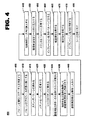
図4は、本発明による血管の病態を治療するシステムを製造する方法の別の実施形態の略図を符号400で示している。 FIG. 4 shows a schematic diagram 400 of another embodiment of a method of manufacturing a system for treating a vascular condition according to the present invention.
この実施形態では、インフレート可能なバルーンを備えたカテーテルを用意する(ブロック405)。カテーテルは、ステントを病変部まで運搬するのに適当な当該技術分野において知られている任意のカテーテルであってよく、例えば、経皮経管的冠動脈形成術(PTCA)バルーンカテーテルである。バルーンは、適当な材料、例えば、ポリエチレン、ポリエチレンテレフタレート(PET)又はナイロン等で作られたものであるのがよい。バルーンの長さ及び直径は、運搬されるステントの寸法形状に応じて選択できる。 In this embodiment, a catheter with an inflatable balloon is provided (block 405). The catheter may be any catheter known in the art suitable for delivering a stent to a lesion, such as a percutaneous transluminal coronary angioplasty (PTCA) balloon catheter. The balloon may be made of a suitable material such as polyethylene, polyethylene terephthalate (PET) or nylon. The length and diameter of the balloon can be selected depending on the size and shape of the stent to be delivered.
バルーンをそのプロフィールを最小限にするよう折り畳み又は違ったやり方で操作し又は処理する(ブロック410)。例えば、バルーンをカテーテルにきつく巻き付けるのがよい。ステントをバルーンに嵌める(ブロック415)。ステントをバルーンに圧着してステントがバルーンにぴったりと装着するようにする(ブロック420)。次に、例えばポリテトラフルオロエチレン(PTFE)等の材料で作られたシースをステントに嵌め(ブロック425)、それによりステントとバルーンの両方を包囲し、ステントを巻き付け状態のバルーンに緊密な締まり嵌め状態で保持する。シースは、単一の管状部材から成るものであってよく、或いはシースは、複数個の管状部材から成るものであってもよい。 The balloon is folded or otherwise manipulated or processed to minimize its profile (block 410). For example, the balloon may be tightly wrapped around the catheter. The stent is fitted into the balloon (block 415). The stent is crimped onto the balloon so that the stent fits snugly onto the balloon (block 420). Next, a sheath made of a material such as polytetrafluoroethylene (PTFE), for example, is fitted to the stent (block 425), thereby enclosing both the stent and the balloon, and a tight interference fit to the wrapped balloon. Hold in state. The sheath may consist of a single tubular member, or the sheath may consist of a plurality of tubular members.
接着剤を流体中へその全体にわたって分散させる(ブロック430)。接着剤は、バルーン材料の融点よりも低い融点、例えば、約165°F(73.9℃)以下の融点を持つ生体適合性材料である。かかる材料の1つは、ポリ(エチレンオキシド)であり、この融点は、140°F〜160°F(60℃〜71.0℃)である。ポリ(エチレンオキシド)を流体、例えば水の中に分散させて希薄溶液を作るのがよい。例えば、3グラム(3g)のポリ(エチレンオキシド)を20立方センチメートル(20cc)の水の中に分散させるのがよい。接着剤を水中で溶解させるため、接着剤及び流体を例えば、約90分の持続時間にわたり95°F〜105°F(35℃〜40.6℃)の温度まで加熱する(ブロック435)。 The adhesive is dispersed throughout the fluid (block 430). The adhesive is a biocompatible material having a melting point that is lower than the melting point of the balloon material, for example, a melting point of about 165 ° F. (73.9 ° C.) or less. One such material is poly (ethylene oxide), which has a melting point of 140 ° F. to 160 ° F. (60 ° C. to 71.0 ° C.). Poly (ethylene oxide) may be dispersed in a fluid such as water to form a dilute solution. For example, 3 grams (3 g) of poly (ethylene oxide) may be dispersed in 20 cubic centimeters (20 cc) of water. To dissolve the adhesive in water, the adhesive and fluid are heated to a temperature of, for example, 95 ° F to 105 ° F (35 ° C to 40.6 ° C) for a duration of about 90 minutes (block 435).
接着剤をステントの内面とバルーンの外面との間に塗布する。これは、例えば、水中に溶けた接着剤から成る接着剤溶液を細い針付きの注射器に入れ(ブロック440)、この針をシース内に挿入し(ブロック445)、接着剤溶液を高圧でシース内の針に通して注入して接着剤がバルーンの外面の少なくとも一部を覆うようにする(ブロック450)。 Adhesive is applied between the inner surface of the stent and the outer surface of the balloon. For example, an adhesive solution consisting of an adhesive dissolved in water is placed in a syringe with a thin needle (Block 440), this needle is inserted into the sheath (Block 445), and the adhesive solution is placed in the sheath at high pressure. Inject through the needle to allow the adhesive to cover at least a portion of the outer surface of the balloon (block 450).
ステントの壁に開口部が形成されている場合、シースは、接着剤をステントとバルーンとの間に差し向けるのと接着剤を収容して接着剤が次のステップ中定位置のままであるようにするのとの両方を助けることができる。 If an opening is formed in the stent wall, the sheath will direct adhesive between the stent and the balloon and contain the adhesive so that the adhesive remains in place during the next step. Can help both.
次に再びステントをバルーンに圧着し(ブロック455)、バルーンを例えば約70PSIのインフレーション圧力で加圧し、それによりバルーンを次の加熱及び冷却ステップ中、部分的にインフレートした形態に維持する(ブロック460)。バルーンを部分的にインフレートさせることにより、バルーンとステントの間に良好な接触状態が得られると共にバルーンがステントの壁に形成された開口部を通り又はステントのいずれの側でも突き出てステントの保持具合を向上させる。シースの内径は、バルーンの突出部の寸法形状を定めるのに役立つことができ、シース内径を次の加熱及び冷却ステップにより永続的に固定するのがよい。 The stent is then again crimped to the balloon (block 455) and the balloon is pressurized, for example, with an inflation pressure of about 70 PSI, thereby maintaining the balloon in a partially inflated configuration during the next heating and cooling steps (block). 460). Partially inflating the balloon provides good contact between the balloon and the stent and holds the stent through the opening formed in the stent wall or on either side of the stent. Improve the condition. The inner diameter of the sheath can help define the dimensions of the balloon protrusion, and the sheath inner diameter should be permanently fixed by subsequent heating and cooling steps.
接着剤をその融点よりも高い温度まで加熱する(ブロック465)。これは、例えば上述した組立体を約3分間、約165°Fの温度状態にヒートセットブロック内で加熱することにより達成できる。 The adhesive is heated to a temperature above its melting point (block 465). This can be accomplished, for example, by heating the assembly described above in a heatset block to a temperature state of about 165 ° F. for about 3 minutes.
次に、接着剤を、例えば、この組立体をヒートセットブロックから取り出して、これを室温で放冷させることにより、その融点よりも低い温度まで冷却する(ブロック470)。組立体がいったん冷えると、インフレーション圧力を中断し(ブロック475)、シースを組立体から取り外す(ブロック480)。 Next, an adhesive, for example, removed the assembly from the heat set block, which by cooling at room temperature, cooled to a temperature below its melting point (Block 470). Once the assembly cools, the inflation pressure is interrupted (block 475) and the sheath is removed from the assembly (block 480).
冷却の際、接着剤は、ステントとバルーンのインターフェイスのところに弱い接着箇所、かくしてステントとバルーンとの間に弱い結合部を形成する。この結合部は、血管内での運搬中、ステントをバルーンに保持する一方、依然として、治療部位でのバルーンのインフレーション及びデフレーションに続いてステントを放出することができる。バルーンを加熱及び冷却ステップ中、部分的に拡張した形態に維持することは、ステントとバルーンとの間に形成される接着層に寄与する場合がある。 Upon cooling, the adhesive forms a weak bond at the stent-balloon interface and thus a weak bond between the stent and the balloon. This joint retains the stent in the balloon during delivery within the vessel while still allowing the stent to be released following balloon inflation and deflation at the treatment site. Maintaining the balloon in a partially expanded configuration during the heating and cooling steps may contribute to the adhesive layer formed between the stent and the balloon.
本明細書において開示した本発明の実施形態は好ましい形態であると現時点において考えられるが、本発明の精神及び範囲から逸脱することなく種々の変更及び改造を行うことができる。本発明の範囲は、特許請求の範囲に記載されており、文言上の意味及び均等範囲に属する全ての変更例及び改造例は、本発明の範囲に含まれるものである。 While the embodiments of the invention disclosed herein are presently considered to be preferred, various changes and modifications can be made without departing from the spirit and scope of the invention. The scope of the present invention is set forth in the appended claims, and all modifications and alterations belonging to the meaning and equivalent range of the words are included in the scope of the present invention.
Claims (4)
インフレート可能なバルーンを備えたカテーテルを用意する段階と、
前記バルーンの上にステントを嵌める段階と、
前記ステントの上にシースを嵌める段階と、
接着剤の塗布に先立って、接着剤を流体中へ、その全体にわたって分散させる段階とを含み、3グラム(3g)の接着剤を20立方センチメートル(20cc)の流体中へ、その全体にわたって分散させ、
前記方法は、さらに、
前記ステントの内面と前記バルーンの外面との間に接着剤を塗る段階と、
前記接着剤を塗った後に、前記ステントを前記バルーンに圧着する段階と、
前記接着剤の融点よりも高い温度に前記接着剤を加熱する段階と、
前記接着剤の融点よりも低い温度に前記接着剤を冷却して、血管内運搬時に、前記カテーテルに前記ステントを保持する接着結合を得る段階とを含み、前記ステントは、治療部位での前記バルーンのインフレーション及びデフレーションにより、前記バルーンから取り除かれるように前記バルーンに接着し、
前記方法は、さらに、
前記接着剤の冷却後、前記シースを取り外す段階を含む、
ことを特徴とする方法。A method of manufacturing a system for treating a vascular condition,
Providing a catheter with an inflatable balloon;
Fitting a stent over the balloon;
Fitting a sheath over the stent ;
Prior to application of the adhesive, the adhesive into the fluid, and a step of dispersing throughout its, the adhesive 3 grams (3 g) into the fluid 20 cm3 (20 cc), is dispersed throughout them,
The method further comprises:
Applying an adhesive between the inner surface of the stent and the outer surface of the balloon;
Crimping the stent to the balloon after applying the adhesive;
Heating the adhesive to a temperature above the melting point of the adhesive;
Cooling the adhesive to a temperature below the melting point of the adhesive to obtain an adhesive bond that holds the stent to the catheter during intravascular delivery, the stent at the treatment site with the balloon Adhere to the balloon to be removed from the balloon by inflation and deflation of
The method further comprises:
Removing the sheath after cooling the adhesive;
A method characterized by that.
インフレート可能なバルーンを備えたカテーテルを用意する段階と、
前記バルーンの上にステントを嵌める段階と、
前記ステントの上にシースを嵌める段階と、
接着剤の塗布に先立って、接着剤を流体中へ、その全体にわたって分散させる段階と、
前記接着剤及び前記流体を加熱して前記流体中の前記接着剤を溶解させる段階と、
前記ステントの内面と前記バルーンの外面との間に接着剤を塗る段階と、
前記接着剤を塗った後に、前記ステントを前記バルーンに圧着する段階と、
前記接着剤の融点よりも高い温度に前記接着剤を加熱する段階と、
前記接着剤の融点よりも低い温度に前記接着剤を冷却して、血管内運搬時に、前記カテーテルに前記ステントを保持する接着結合を得る段階とを含み、前記ステントは、治療部位での前記バルーンのインフレーション及びデフレーションにより、前記バルーンから取り除かれるように前記バルーンに接着し、
前記方法は、さらに、
前記接着剤の冷却後、前記シースを取り外す段階を含む、
ことを特徴とする方法。A method of manufacturing a system for treating a vascular condition,
Providing a catheter with an inflatable balloon;
Fitting a stent over the balloon;
Fitting a sheath over the stent ;
Prior to application of the adhesive, the adhesive into the fluid, the method comprising dispersing over its entire,
Heating the adhesive and the fluid to dissolve the adhesive in the fluid;
Applying an adhesive between the inner surface of the stent and the outer surface of the balloon;
Crimping the stent to the balloon after applying the adhesive;
Heating the adhesive to a temperature above the melting point of the adhesive;
Cooling the adhesive to a temperature below the melting point of the adhesive to obtain an adhesive bond that holds the stent to the catheter during intravascular delivery, the stent at the treatment site with the balloon Adhere to the balloon to be removed from the balloon by inflation and deflation of
The method further comprises:
Removing the sheath after cooling the adhesive;
A method characterized by that.
インフレート可能なバルーンを備えたカテーテルを用意する段階と、
前記バルーンの上にステントを嵌める段階と、
前記ステントの上にシースを嵌める段階と、
接着剤の塗布に先立って、接着剤を流体中へ、その全体にわたって分散させる段階と、
前記ステントの内面と前記バルーンの外面との間に接着剤を塗る段階とを含み、
前記接着剤を塗る前記段階は、
細い針を備えた注射器内に前記接着剤を入れ、
前記シース内に前記針を挿入し、
前記シース内の前記針を通して前記接着剤を注入して、前記接着剤が前記バルーンの前記外面の少なくとも一部を被覆するようにすることを含み、
前記方法は、さらに、
前記接着剤を塗った後に、前記ステントを前記バルーンに圧着する段階と、
前記接着剤の融点よりも高い温度に前記接着剤を加熱する段階と、
前記接着剤の融点よりも低い温度に前記接着剤を冷却して、血管内運搬時に、前記カテーテルに前記ステントを保持する接着結合を得る段階とを含み、前記ステントは、治療部位での前記バルーンのインフレーション及びデフレーションにより、前記バルーンから取り除かれるように前記バルーンに接着し、
前記方法は、さらに、
前記接着剤の冷却後、前記シースを取り外す段階を含む、
ことを特徴とする方法。A method of manufacturing a system for treating a vascular condition,
Providing a catheter with an inflatable balloon;
Fitting a stent over the balloon;
Fitting a sheath over the stent ;
Prior to application of the adhesive, the adhesive into the fluid, the method comprising dispersing over its entire,
Applying an adhesive between the inner surface of the stent and the outer surface of the balloon;
The step of applying the adhesive comprises:
Put the adhesive in a syringe with a thin needle,
Inserting the needle into the sheath;
Injecting the adhesive through the needle in the sheath such that the adhesive covers at least a portion of the outer surface of the balloon;
The method further comprises:
Crimping the stent to the balloon after applying the adhesive;
Heating the adhesive to a temperature above the melting point of the adhesive;
Cooling the adhesive to a temperature below the melting point of the adhesive to obtain an adhesive bond that holds the stent to the catheter during intravascular delivery, the stent at the treatment site with the balloon Adhere to the balloon to be removed from the balloon by inflation and deflation of
The method further comprises:
Removing the sheath after cooling the adhesive;
A method characterized by that.
Applications Claiming Priority (2)
| Application Number | Priority Date | Filing Date | Title |
|---|---|---|---|
| US10/823,216 US6958073B2 (en) | 2003-04-21 | 2004-04-13 | Method and system for stent retention using an adhesive |
| PCT/US2005/010007 WO2005102218A1 (en) | 2004-04-13 | 2005-03-23 | Method and system for stent retention using an adhesive |
Publications (3)
| Publication Number | Publication Date |
|---|---|
| JP2007532241A JP2007532241A (en) | 2007-11-15 |
| JP2007532241A5 JP2007532241A5 (en) | 2008-05-15 |
| JP4279891B2 true JP4279891B2 (en) | 2009-06-17 |
Family
ID=34965326
Family Applications (1)
| Application Number | Title | Priority Date | Filing Date |
|---|---|---|---|
| JP2007508365A Expired - Fee Related JP4279891B2 (en) | 2004-04-13 | 2005-03-23 | Method of manufacturing a system for treating a vascular condition |
Country Status (6)
| Country | Link |
|---|---|
| US (1) | US6958073B2 (en) |
| EP (1) | EP1755485B1 (en) |
| JP (1) | JP4279891B2 (en) |
| AT (1) | ATE466546T1 (en) |
| DE (1) | DE602005021101D1 (en) |
| WO (1) | WO2005102218A1 (en) |
Families Citing this family (28)
| Publication number | Priority date | Publication date | Assignee | Title |
|---|---|---|---|---|
| AU2002348180A1 (en) | 2001-11-09 | 2003-05-26 | Novoste Corporation | Baloon catheter with non-deployable stent |
| US20040111108A1 (en) | 2001-11-09 | 2004-06-10 | Farnan Robert C. | Balloon catheter with non-deployable stent |
| US8080026B2 (en) | 2003-01-21 | 2011-12-20 | Angioscore, Inc. | Apparatus and methods for treating hardened vascular lesions |
| US20060178721A1 (en) * | 2005-02-10 | 2006-08-10 | Advanced Cardiovascular Systems, Inc. | Stent delivery balloon catheter having improved stent retention |
| US7763198B2 (en) * | 2005-04-12 | 2010-07-27 | Abbott Cardiovascular Systems Inc. | Method for retaining a vascular stent on a catheter |
| US10076641B2 (en) | 2005-05-11 | 2018-09-18 | The Spectranetics Corporation | Methods and systems for delivering substances into luminal walls |
| US7886419B2 (en) * | 2006-07-18 | 2011-02-15 | Advanced Cardiovascular Systems, Inc. | Stent crimping apparatus and method |
| US8062465B1 (en) | 2006-08-02 | 2011-11-22 | Abbott Cardiovascular Systems Inc. | Methods for improved stent retention |
| US8177798B2 (en) | 2006-12-05 | 2012-05-15 | Tyco Healthcare Group Lp | Adhesive coated stent and insertion instrument |
| US8986253B2 (en) | 2008-01-25 | 2015-03-24 | Tandem Diabetes Care, Inc. | Two chamber pumps and related methods |
| US8042251B2 (en) * | 2008-05-21 | 2011-10-25 | Boston Scientific Scimed, Inc. | Systems and methods for heating and cooling during stent crimping |
| US8291570B2 (en) | 2008-05-30 | 2012-10-23 | Boston Scientific Scimed, Inc. | Methods for abluminally coating medical devices |
| US8408421B2 (en) | 2008-09-16 | 2013-04-02 | Tandem Diabetes Care, Inc. | Flow regulating stopcocks and related methods |
| EP2334234A4 (en) | 2008-09-19 | 2013-03-20 | Tandem Diabetes Care Inc | Solute concentration measurement device and related methods |
| CA2921304C (en) | 2009-07-30 | 2018-06-05 | Tandem Diabetes Care, Inc. | Infusion pump system with disposable cartridge having pressure venting and pressure feedback |
| US9199066B2 (en) | 2010-03-12 | 2015-12-01 | Quattro Vascular Pte Ltd. | Device and method for compartmental vessel treatment |
| EP2380604A1 (en) | 2010-04-19 | 2011-10-26 | InnoRa Gmbh | Improved coating formulations for scoring or cutting balloon catheters |
| US8632559B2 (en) | 2010-09-21 | 2014-01-21 | Angioscore, Inc. | Method and system for treating valve stenosis |
| EP2601995B1 (en) * | 2011-12-07 | 2022-08-17 | CAR Holding B.V. | An arrangement for implementing kissing balloons for simulating a bifurcated vessel, a kit, a method of manufacturing the arrangement and a catheter provided with a buffer volume. |
| WO2013114201A1 (en) | 2012-02-01 | 2013-08-08 | Tanhum Feld | Device for compartmental dilatation of blood vessels |
| EP3542849B1 (en) | 2012-02-08 | 2020-12-09 | TriReme Medical, LLC | Constraining structure with non-linear axial struts |
| US9216033B2 (en) | 2012-02-08 | 2015-12-22 | Quattro Vascular Pte Ltd. | System and method for treating biological vessels |
| US9180242B2 (en) | 2012-05-17 | 2015-11-10 | Tandem Diabetes Care, Inc. | Methods and devices for multiple fluid transfer |
| US9555186B2 (en) | 2012-06-05 | 2017-01-31 | Tandem Diabetes Care, Inc. | Infusion pump system with disposable cartridge having pressure venting and pressure feedback |
| US9173998B2 (en) | 2013-03-14 | 2015-11-03 | Tandem Diabetes Care, Inc. | System and method for detecting occlusions in an infusion pump |
| US10117668B2 (en) | 2013-10-08 | 2018-11-06 | The Spectranetics Corporation | Balloon catheter with non-deployable stent having improved stability |
| CN106572846B (en) | 2014-05-23 | 2020-01-21 | 波士顿科学国际有限公司 | Deployment system for bonding adhesive applications |
| JP6803838B2 (en) | 2014-11-17 | 2020-12-23 | トライレム・メディカル・エルエルシー | Balloon catheter system and how to use this system |
Family Cites Families (12)
| Publication number | Priority date | Publication date | Assignee | Title |
|---|---|---|---|---|
| US4733665C2 (en) * | 1985-11-07 | 2002-01-29 | Expandable Grafts Partnership | Expandable intraluminal graft and method and apparatus for implanting an expandable intraluminal graft |
| US5133732A (en) * | 1987-10-19 | 1992-07-28 | Medtronic, Inc. | Intravascular stent |
| US5292331A (en) * | 1989-08-24 | 1994-03-08 | Applied Vascular Engineering, Inc. | Endovascular support device |
| CA2079417C (en) * | 1991-10-28 | 2003-01-07 | Lilip Lau | Expandable stents and method of making same |
| US5836965A (en) * | 1994-10-19 | 1998-11-17 | Jendersee; Brad | Stent delivery and deployment method |
| US5674242A (en) * | 1995-06-06 | 1997-10-07 | Quanam Medical Corporation | Endoprosthetic device with therapeutic compound |
| US5776161A (en) * | 1995-10-16 | 1998-07-07 | Instent, Inc. | Medical stents, apparatus and method for making same |
| US6066156A (en) * | 1999-03-11 | 2000-05-23 | Advanced Cardiovascular Systems, Inc. | Temperature activated adhesive for releasably attaching stents to balloons |
| US6682553B1 (en) * | 2000-12-28 | 2004-01-27 | Advanced Cardiovascular Systems, Inc. | System and method for stent retention |
| US6620191B1 (en) * | 2001-03-27 | 2003-09-16 | Advanced Cardiovascular Systems, Inc. | System for releasably securing a stent on a catheter assembly and method of use |
| US6666880B1 (en) * | 2001-06-19 | 2003-12-23 | Advised Cardiovascular Systems, Inc. | Method and system for securing a coated stent to a balloon catheter |
| US7198637B2 (en) * | 2003-04-21 | 2007-04-03 | Medtronic Vascular, Inc. | Method and system for stent retention using an adhesive |
-
2004
- 2004-04-13 US US10/823,216 patent/US6958073B2/en not_active Expired - Lifetime
-
2005
- 2005-03-23 WO PCT/US2005/010007 patent/WO2005102218A1/en active Application Filing
- 2005-03-23 AT AT05734344T patent/ATE466546T1/en not_active IP Right Cessation
- 2005-03-23 JP JP2007508365A patent/JP4279891B2/en not_active Expired - Fee Related
- 2005-03-23 DE DE602005021101T patent/DE602005021101D1/en active Active
- 2005-03-23 EP EP05734344A patent/EP1755485B1/en not_active Not-in-force
Also Published As
| Publication number | Publication date |
|---|---|
| ATE466546T1 (en) | 2010-05-15 |
| US6958073B2 (en) | 2005-10-25 |
| EP1755485A1 (en) | 2007-02-28 |
| US20040210299A1 (en) | 2004-10-21 |
| WO2005102218A1 (en) | 2005-11-03 |
| JP2007532241A (en) | 2007-11-15 |
| EP1755485B1 (en) | 2010-05-05 |
| DE602005021101D1 (en) | 2010-06-17 |
Similar Documents
| Publication | Publication Date | Title |
|---|---|---|
| JP4279891B2 (en) | Method of manufacturing a system for treating a vascular condition | |
| US7198637B2 (en) | Method and system for stent retention using an adhesive | |
| JP6741706B2 (en) | lattice | |
| JP4344384B2 (en) | Method and system for treating side branch ostium | |
| US6576006B2 (en) | Self-expanding stent delivery system | |
| US8262687B2 (en) | Stent holding member and stent feeding system | |
| US20080033524A1 (en) | Heated balloon assembly for delivery of polymeric stents | |
| US6986785B2 (en) | Stent balloon assembly and methods of making same | |
| US20040230176A1 (en) | System for treating a vascular condition that inhibits restenosis at stent ends | |
| US20060015170A1 (en) | Contrast coated stent and method of fabrication | |
| US20030181973A1 (en) | Reduced restenosis drug containing stents | |
| US20060009832A1 (en) | Balloon catheter and method and system for securing a stent to a balloon catheter | |
| US7651525B2 (en) | Intraluminal stent assembly and method of deploying the same | |
| US8679572B2 (en) | Coated stent | |
| JP2017510367A (en) | Implant delivery system | |
| US20060206187A1 (en) | Stent delivery system | |
| JP2008502441A (en) | Stent delivery system | |
| JP6267214B2 (en) | Method for crimping a bioresorbable stent | |
| US7105014B2 (en) | Stent delivery and retention apparatus | |
| WO2010107948A1 (en) | Ostial lesion stent delivery system | |
| US20060036308A1 (en) | Stent with extruded covering | |
| US20060178721A1 (en) | Stent delivery balloon catheter having improved stent retention | |
| US20040215314A1 (en) | Stent deployment assembly with collars for drug-eluting stent | |
| US20040215311A1 (en) | Method and system for improving stent retention using stent openings | |
| US20060074396A1 (en) | Stent delivery system |
Legal Events
| Date | Code | Title | Description |
|---|---|---|---|
| A521 | Request for written amendment filed |
Free format text: JAPANESE INTERMEDIATE CODE: A523 Effective date: 20080324 |
|
| A621 | Written request for application examination |
Free format text: JAPANESE INTERMEDIATE CODE: A621 Effective date: 20080324 |
|
| A871 | Explanation of circumstances concerning accelerated examination |
Free format text: JAPANESE INTERMEDIATE CODE: A871 Effective date: 20080324 |
|
| A975 | Report on accelerated examination |
Free format text: JAPANESE INTERMEDIATE CODE: A971005 Effective date: 20080428 |
|
| A131 | Notification of reasons for refusal |
Free format text: JAPANESE INTERMEDIATE CODE: A131 Effective date: 20080609 |
|
| A521 | Request for written amendment filed |
Free format text: JAPANESE INTERMEDIATE CODE: A523 Effective date: 20080909 |
|
| A131 | Notification of reasons for refusal |
Free format text: JAPANESE INTERMEDIATE CODE: A131 Effective date: 20081110 |
|
| A521 | Request for written amendment filed |
Free format text: JAPANESE INTERMEDIATE CODE: A523 Effective date: 20090210 |
|
| TRDD | Decision of grant or rejection written | ||
| A01 | Written decision to grant a patent or to grant a registration (utility model) |
Free format text: JAPANESE INTERMEDIATE CODE: A01 Effective date: 20090309 |
|
| A01 | Written decision to grant a patent or to grant a registration (utility model) |
Free format text: JAPANESE INTERMEDIATE CODE: A01 |
|
| A61 | First payment of annual fees (during grant procedure) |
Free format text: JAPANESE INTERMEDIATE CODE: A61 Effective date: 20090312 |
|
| FPAY | Renewal fee payment (event date is renewal date of database) |
Free format text: PAYMENT UNTIL: 20120319 Year of fee payment: 3 |
|
| R150 | Certificate of patent or registration of utility model |
Free format text: JAPANESE INTERMEDIATE CODE: R150 |
|
| FPAY | Renewal fee payment (event date is renewal date of database) |
Free format text: PAYMENT UNTIL: 20120319 Year of fee payment: 3 |
|
| FPAY | Renewal fee payment (event date is renewal date of database) |
Free format text: PAYMENT UNTIL: 20130319 Year of fee payment: 4 |
|
| FPAY | Renewal fee payment (event date is renewal date of database) |
Free format text: PAYMENT UNTIL: 20130319 Year of fee payment: 4 |
|
| FPAY | Renewal fee payment (event date is renewal date of database) |
Free format text: PAYMENT UNTIL: 20140319 Year of fee payment: 5 |
|
| R250 | Receipt of annual fees |
Free format text: JAPANESE INTERMEDIATE CODE: R250 |
|
| LAPS | Cancellation because of no payment of annual fees |