JP4274100B2 - Engine control device - Google Patents
Engine control device Download PDFInfo
- Publication number
- JP4274100B2 JP4274100B2 JP2004298137A JP2004298137A JP4274100B2 JP 4274100 B2 JP4274100 B2 JP 4274100B2 JP 2004298137 A JP2004298137 A JP 2004298137A JP 2004298137 A JP2004298137 A JP 2004298137A JP 4274100 B2 JP4274100 B2 JP 4274100B2
- Authority
- JP
- Japan
- Prior art keywords
- torque
- engine
- control
- shift
- rotation
- Prior art date
- Legal status (The legal status is an assumption and is not a legal conclusion. Google has not performed a legal analysis and makes no representation as to the accuracy of the status listed.)
- Active
Links
- 230000005540 biological transmission Effects 0.000 claims description 18
- XLYOFNOQVPJJNP-UHFFFAOYSA-N water Substances O XLYOFNOQVPJJNP-UHFFFAOYSA-N 0.000 claims description 18
- 230000007423 decrease Effects 0.000 claims description 15
- 230000003247 decreasing effect Effects 0.000 claims description 8
- 238000013459 approach Methods 0.000 claims description 2
- 230000001360 synchronised effect Effects 0.000 description 16
- 238000004364 calculation method Methods 0.000 description 12
- 230000035939 shock Effects 0.000 description 12
- 230000001052 transient effect Effects 0.000 description 12
- 230000007246 mechanism Effects 0.000 description 7
- 238000000034 method Methods 0.000 description 6
- 230000008569 process Effects 0.000 description 5
- 230000008859 change Effects 0.000 description 4
- 238000010586 diagram Methods 0.000 description 4
- 238000004904 shortening Methods 0.000 description 4
- 230000008878 coupling Effects 0.000 description 3
- 238000010168 coupling process Methods 0.000 description 3
- 238000005859 coupling reaction Methods 0.000 description 3
- 230000007704 transition Effects 0.000 description 3
- 230000005764 inhibitory process Effects 0.000 description 2
- 238000007562 laser obscuration time method Methods 0.000 description 2
- 230000000116 mitigating effect Effects 0.000 description 2
- 230000009467 reduction Effects 0.000 description 2
- 230000004044 response Effects 0.000 description 2
- 238000004891 communication Methods 0.000 description 1
- 239000002826 coolant Substances 0.000 description 1
- 230000003111 delayed effect Effects 0.000 description 1
- 230000000694 effects Effects 0.000 description 1
- 238000005516 engineering process Methods 0.000 description 1
- 239000000446 fuel Substances 0.000 description 1
- 238000002347 injection Methods 0.000 description 1
- 239000007924 injection Substances 0.000 description 1
- 230000007257 malfunction Effects 0.000 description 1
- 230000000979 retarding effect Effects 0.000 description 1
Images


Classifications
-
- F—MECHANICAL ENGINEERING; LIGHTING; HEATING; WEAPONS; BLASTING
- F02—COMBUSTION ENGINES; HOT-GAS OR COMBUSTION-PRODUCT ENGINE PLANTS
- F02P—IGNITION, OTHER THAN COMPRESSION IGNITION, FOR INTERNAL-COMBUSTION ENGINES; TESTING OF IGNITION TIMING IN COMPRESSION-IGNITION ENGINES
- F02P5/00—Advancing or retarding ignition; Control therefor
- F02P5/04—Advancing or retarding ignition; Control therefor automatically, as a function of the working conditions of the engine or vehicle or of the atmospheric conditions
- F02P5/145—Advancing or retarding ignition; Control therefor automatically, as a function of the working conditions of the engine or vehicle or of the atmospheric conditions using electrical means
- F02P5/15—Digital data processing
- F02P5/1502—Digital data processing using one central computing unit
- F02P5/1504—Digital data processing using one central computing unit with particular means during a transient phase, e.g. acceleration, deceleration, gear change
-
- B—PERFORMING OPERATIONS; TRANSPORTING
- B60—VEHICLES IN GENERAL
- B60W—CONJOINT CONTROL OF VEHICLE SUB-UNITS OF DIFFERENT TYPE OR DIFFERENT FUNCTION; CONTROL SYSTEMS SPECIALLY ADAPTED FOR HYBRID VEHICLES; ROAD VEHICLE DRIVE CONTROL SYSTEMS FOR PURPOSES NOT RELATED TO THE CONTROL OF A PARTICULAR SUB-UNIT
- B60W10/00—Conjoint control of vehicle sub-units of different type or different function
- B60W10/04—Conjoint control of vehicle sub-units of different type or different function including control of propulsion units
- B60W10/06—Conjoint control of vehicle sub-units of different type or different function including control of propulsion units including control of combustion engines
-
- B—PERFORMING OPERATIONS; TRANSPORTING
- B60—VEHICLES IN GENERAL
- B60W—CONJOINT CONTROL OF VEHICLE SUB-UNITS OF DIFFERENT TYPE OR DIFFERENT FUNCTION; CONTROL SYSTEMS SPECIALLY ADAPTED FOR HYBRID VEHICLES; ROAD VEHICLE DRIVE CONTROL SYSTEMS FOR PURPOSES NOT RELATED TO THE CONTROL OF A PARTICULAR SUB-UNIT
- B60W30/00—Purposes of road vehicle drive control systems not related to the control of a particular sub-unit, e.g. of systems using conjoint control of vehicle sub-units
- B60W30/18—Propelling the vehicle
- B60W30/19—Improvement of gear change, e.g. by synchronisation or smoothing gear shift
-
- F—MECHANICAL ENGINEERING; LIGHTING; HEATING; WEAPONS; BLASTING
- F02—COMBUSTION ENGINES; HOT-GAS OR COMBUSTION-PRODUCT ENGINE PLANTS
- F02D—CONTROLLING COMBUSTION ENGINES
- F02D37/00—Non-electrical conjoint control of two or more functions of engines, not otherwise provided for
- F02D37/02—Non-electrical conjoint control of two or more functions of engines, not otherwise provided for one of the functions being ignition
-
- F—MECHANICAL ENGINEERING; LIGHTING; HEATING; WEAPONS; BLASTING
- F02—COMBUSTION ENGINES; HOT-GAS OR COMBUSTION-PRODUCT ENGINE PLANTS
- F02D—CONTROLLING COMBUSTION ENGINES
- F02D41/00—Electrical control of supply of combustible mixture or its constituents
- F02D41/02—Circuit arrangements for generating control signals
- F02D41/021—Introducing corrections for particular conditions exterior to the engine
- F02D41/0215—Introducing corrections for particular conditions exterior to the engine in relation with elements of the transmission
- F02D41/023—Introducing corrections for particular conditions exterior to the engine in relation with elements of the transmission in relation with the gear ratio shifting
-
- F—MECHANICAL ENGINEERING; LIGHTING; HEATING; WEAPONS; BLASTING
- F02—COMBUSTION ENGINES; HOT-GAS OR COMBUSTION-PRODUCT ENGINE PLANTS
- F02D—CONTROLLING COMBUSTION ENGINES
- F02D41/00—Electrical control of supply of combustible mixture or its constituents
- F02D41/02—Circuit arrangements for generating control signals
- F02D41/14—Introducing closed-loop corrections
- F02D41/1497—With detection of the mechanical response of the engine
-
- F—MECHANICAL ENGINEERING; LIGHTING; HEATING; WEAPONS; BLASTING
- F16—ENGINEERING ELEMENTS AND UNITS; GENERAL MEASURES FOR PRODUCING AND MAINTAINING EFFECTIVE FUNCTIONING OF MACHINES OR INSTALLATIONS; THERMAL INSULATION IN GENERAL
- F16H—GEARING
- F16H61/00—Control functions within control units of change-speed- or reversing-gearings for conveying rotary motion ; Control of exclusively fluid gearing, friction gearing, gearings with endless flexible members or other particular types of gearing
- F16H61/04—Smoothing ratio shift
- F16H61/0403—Synchronisation before shifting
-
- F—MECHANICAL ENGINEERING; LIGHTING; HEATING; WEAPONS; BLASTING
- F16—ENGINEERING ELEMENTS AND UNITS; GENERAL MEASURES FOR PRODUCING AND MAINTAINING EFFECTIVE FUNCTIONING OF MACHINES OR INSTALLATIONS; THERMAL INSULATION IN GENERAL
- F16H—GEARING
- F16H63/00—Control outputs from the control unit to change-speed- or reversing-gearings for conveying rotary motion or to other devices than the final output mechanism
- F16H63/40—Control outputs from the control unit to change-speed- or reversing-gearings for conveying rotary motion or to other devices than the final output mechanism comprising signals other than signals for actuating the final output mechanisms
- F16H63/50—Signals to an engine or motor
- F16H63/502—Signals to an engine or motor for smoothing gear shifts
-
- B—PERFORMING OPERATIONS; TRANSPORTING
- B60—VEHICLES IN GENERAL
- B60W—CONJOINT CONTROL OF VEHICLE SUB-UNITS OF DIFFERENT TYPE OR DIFFERENT FUNCTION; CONTROL SYSTEMS SPECIALLY ADAPTED FOR HYBRID VEHICLES; ROAD VEHICLE DRIVE CONTROL SYSTEMS FOR PURPOSES NOT RELATED TO THE CONTROL OF A PARTICULAR SUB-UNIT
- B60W2710/00—Output or target parameters relating to a particular sub-units
- B60W2710/06—Combustion engines, Gas turbines
- B60W2710/0666—Engine torque
-
- B—PERFORMING OPERATIONS; TRANSPORTING
- B60—VEHICLES IN GENERAL
- B60Y—INDEXING SCHEME RELATING TO ASPECTS CROSS-CUTTING VEHICLE TECHNOLOGY
- B60Y2300/00—Purposes or special features of road vehicle drive control systems
- B60Y2300/43—Control of engines
- B60Y2300/436—Control of engine ignition
-
- F—MECHANICAL ENGINEERING; LIGHTING; HEATING; WEAPONS; BLASTING
- F02—COMBUSTION ENGINES; HOT-GAS OR COMBUSTION-PRODUCT ENGINE PLANTS
- F02D—CONTROLLING COMBUSTION ENGINES
- F02D2250/00—Engine control related to specific problems or objectives
- F02D2250/18—Control of the engine output torque
- F02D2250/21—Control of the engine output torque during a transition between engine operation modes or states
-
- Y—GENERAL TAGGING OF NEW TECHNOLOGICAL DEVELOPMENTS; GENERAL TAGGING OF CROSS-SECTIONAL TECHNOLOGIES SPANNING OVER SEVERAL SECTIONS OF THE IPC; TECHNICAL SUBJECTS COVERED BY FORMER USPC CROSS-REFERENCE ART COLLECTIONS [XRACs] AND DIGESTS
- Y02—TECHNOLOGIES OR APPLICATIONS FOR MITIGATION OR ADAPTATION AGAINST CLIMATE CHANGE
- Y02T—CLIMATE CHANGE MITIGATION TECHNOLOGIES RELATED TO TRANSPORTATION
- Y02T10/00—Road transport of goods or passengers
- Y02T10/10—Internal combustion engine [ICE] based vehicles
- Y02T10/40—Engine management systems
Landscapes
- Engineering & Computer Science (AREA)
- Mechanical Engineering (AREA)
- General Engineering & Computer Science (AREA)
- Chemical & Material Sciences (AREA)
- Combustion & Propulsion (AREA)
- Transportation (AREA)
- Theoretical Computer Science (AREA)
- Signal Processing (AREA)
- Automation & Control Theory (AREA)
- Electrical Control Of Ignition Timing (AREA)
- Combined Controls Of Internal Combustion Engines (AREA)
- Control Of Vehicle Engines Or Engines For Specific Uses (AREA)
Description
本発明は、自動変速機の変速時にエンジン出力を制御することによって変速時間を短縮しつつ変速ショックを低減するエンジンの制御装置に関する。 The present invention relates to an engine control device that reduces a shift shock while shortening a shift time by controlling an engine output during a shift of an automatic transmission.
有段の変速機構を有する自動変速機のダウンシフト時に、エンジン出力(トルク)を増加させて、ダウンシフト後のエンジン回転速度に近づけておいてから変速を行うことで変速ショックを低減するようにした技術が知られている。なお、特許文献1に記載の技術では、上記ダウンシフト時のスロットル開度増大等のトルクアップ制御に点火時期リタード制御(トルクダウン制御)を併用して、実変速作動前のトルクが上がりすぎることを抑制している。
ところで、上記ダウンシフト時のトルクアップ制御では、例えば、変速後の回転速度に同期するように初期にはトルクアップ量を大きくして速やかに同期速度まで上昇させ、その後は、該同期速度を維持できるだけのトルクに減少させて、次段クラッチを結合操作し、結合完了後、ドライバ要求トルク(アクセル開放時は負のトルク)まで、減少するような、制御を行うことで、変速時間の短縮を図りつつ変速ショックを緩和できる。 By the way, in the torque up control at the time of downshift, for example, the amount of torque increase is initially increased so as to synchronize with the rotational speed after the shift, and the speed is rapidly increased to the synchronous speed, and thereafter, the synchronous speed is maintained. By reducing the torque to as much as possible, the next-stage clutch is engaged, and after completion of the engagement, control is performed to reduce the torque to the driver's required torque (negative torque when the accelerator is released), thereby shortening the shift time. Shift shock can be reduced while aiming.
しかしながら、上記のようなトルクアップ制御の途中あるいは終了時に、スロットル弁を急速に閉じてトルクを急減するような制御を行っても、実際には、マニホールド容積によって吸入空気量の減少に遅れを生じるので、十分にトルクを低減しきれず、余剰トルクによって押し出され感を生じるなど、安定した減速感を得られないことがあった。
本発明は、このような従来の課題に着目してなされたもので、ダウンシフト時に短時間で変速ショックを緩和しつつ、押し出され感の発生を抑制して良好な変速性を確保できるようにすることを目的とする。
However, even if control is performed such that the throttle valve is rapidly closed and the torque is suddenly reduced during or at the end of the torque increase control as described above, in practice, there is a delay in the reduction of the intake air amount due to the manifold volume. As a result, the torque cannot be reduced sufficiently, and a stable feeling of deceleration may not be obtained, for example, a feeling of being pushed out by the surplus torque.
The present invention has been made by paying attention to such a conventional problem, so that a good shock can be ensured by suppressing the occurrence of a feeling of being pushed out while mitigating a shift shock in a short time during a downshift. The purpose is to do.
このため本発明では、自動変速機のダウンシフト操作時に、エンジン回転速度を変速後のエンジン回転速度に近づけるように、スロットル開度を増大してエンジン出力を増大するエンジン制御装置において、前記エンジン出力の増大制御で増加したエンジンの出力トルクをスロットル開度を減少して急減させるときに、実トルクが目標トルクを上回る余剰トルク分を、点火時期のリタード制御によるトルク減少分で相殺する構成とした。 Therefore, according to the present invention, in the engine control device that increases the engine output by increasing the throttle opening so that the engine rotation speed approaches the engine rotation speed after the shift during the downshift operation of the automatic transmission, When the output torque of the engine increased by the increase control of the engine is suddenly decreased by decreasing the throttle opening, the excess torque exceeding the target torque is offset by the torque decrease by the ignition timing retard control. .
本発明に係るエンジンの変速用制御装置では、ダウンシフト時の変速ショック緩和のためのエンジン出力増大制御時に、増加したエンジントルクを急減させるときに、吸入空気量の減少遅れによって実トルクが目標トルクを上回る余剰分を、点火時期のリタード制御によるトルク減少分で相殺することができ、もって、変速ショック(突き上げショック)を十分に緩和することができる。 In the engine shift control device according to the present invention, when the increased engine torque is suddenly decreased during the engine output increase control for mitigating the shift shock during the downshift, the actual torque is set to the target torque due to the delay in the reduction of the intake air amount. Can be offset by the torque decrease due to the retard control of the ignition timing, so that the shift shock (push-up shock) can be sufficiently mitigated.
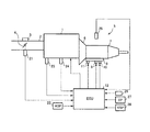
以下、本発明の実施形態を図面に基づいて説明する。図1は、本発明の実施形態に係るエンジンのシステム構成図である。
図1において、エンジン1の吸気通路2には、スロットルモータ3で駆動されるスロットル弁4が設けられている。エンジン1の出力側には、自動変速機5が連結されている。
この自動変速機5は、自動変速モードの他に、ドライバの要求によって手動変速が可能な手動変速モードを有するものであって、エンジン1の出力軸に連結されるトルクコンバータ6と、このトルクコンバータ6の出力側に連結される変速機構(ギア機構)7と、この変速機構7中の各種変速要素(クラッチ等)の結合・開放操作を行う油圧制御機構8と、を備えている。
Hereinafter, embodiments of the present invention will be described with reference to the drawings. FIG. 1 is a system configuration diagram of an engine according to an embodiment of the present invention.
In FIG. 1, a
The
前記油圧制御機構8に対する作動油圧は、各種の電磁バルブを介して制御されるが、ここでは自動変速のためのシフトソレノイド9、10と、前記トルクコンバータ6のロックアップのためのロックアップソレノイド11のみを示してある。なお、前記シフトソレノイド9、10および前記ロックアップソレノイド11は、電子コントロールユニット(以下、ECUという)12に接続されている。
The hydraulic pressure for the
ECU12には、スロットル弁4の開度を検出するスロットルセンサ21、アクセルペダルの踏み込み量APSを検出するアクセル開度センサ22、エンジン冷却水温度Twを検出する水温センサ23、エンジン回転速度Neを検出する回転速度センサ24、自動変速機5(のギア機構)のギア位置Gpを検出するギア位置センサ25、ドライバが操作して自動変速機5の変速モード(自動変速モード、手動変速モード)を設定するモードスイッチ26、シフトレバー位置SPを検出するシフト位置センサ27,車両の速度VSPを検出する車速センサ28等からの信号が入力される。
The ECU 12 includes a
前記、ECU12は、エンジン制御を行うEGCU部12Aと、自動変速機側の制御を行うATCU部12Bとを含んで構成される。
ATCU部12Bは、自動変速モードにおいては、アクセル操作量APSおよび車速VSPに基づいて、あらかじめ設定されたマップを参照すること等によって最適な変速段を設定し、設定した変速段となるように前記シフトソレノイド14、15を制御する。一方、手動変速モードにおいては、ドライバがシフトレバーを介して行うアップシフト操作またはダウンシフト操作に応じて、それぞれ現在の変速段よりも1段づつアップシフト側またはダウンシフト側の変速段を設定し、この変速段となるように前記シフトソレノイド14、15を制御する。
The ECU 12 includes an EGCU
In the automatic shift mode, the
一方、EGCU部12Aは、前記各種センサ類からの信号に基づいて燃料噴射制御、点火時期制御等のエンジン制御を実行すると共に、目標エンジントルクを演算し、この目標エンジントルクが得られるように、前記スロットルモータ5を駆動してスロットル弁4の開度を制御してエンジン出力制御を行う。ここで、EGCU部によって実行されるダウンシフト時のエンジン出力増大制御(回転同期制御)について説明する。
On the other hand, the EGCU
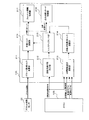
図2は、前記EGCU部12Aによるダウンシフト時を含むエンジン出力制御を示したブロック図である。
ドライバ要求トルク演算部211では、アクセル開度センサ22からのアクセル操作量(アクセル開度)APSに基づいてドライバの要求するエンジントルクをドライバ要求トルクTTEIFとして演算する。
FIG. 2 is a block diagram showing engine output control including downshift by the EGCU
The driver
回転同期作動判定部212では、回転同期制御を行うと不都合な状態、例えば、後述するように回転同期要求トルクが過渡的に変化するときの点火時期リタード制御を行えない場合やATCU〜EGCU間の通信エラーによる誤動作となるような状態を判定する。
目標回転速度演算部213では、ATCU部から、回転同期要求信号(回転同期要求フラグ)、変速機出力軸回転速度信号(=車速信号)、現在の変速前ギア位置信号、変速後ギア信号を入力し、手動変速モードでダウンシフト操作されたとき、すなわち、回転同期制御の要求が発生したときに、変速後ギア信号に基づいて変速後ギア位置に同期した目標回転速度を演算する。
In the rotation synchronization
The target rotation
同期要求トルク演算部214は、前記目標回転速度演算部212で演算された目標回転速度とするのに必要なエンジントルクを同期要求トルクTQTMSTACとして演算する。
トルクアップフェイルセーフ部215は、回転同期制御の要求の有無、前記回転同期作動判定部212で回転同期制御を禁止された条件に応じて、必要時のみ回転同期制御を実行させるようにする。
The synchronization required
The torque-
目標トルク演算部216は、回転同期制御要求の有無に応じて前記ドライバ要求トルク演算部211で演算されたドライバ要求トルクTTEIFと、前記トルクアップフェイルセーフ部215でフェールセーフ処理済みの同期要求トルクTQTMSTACを目標トルクとして演算(選択)する。ここで、目標トルクを、目標定常トルクと、目標過渡トルクとに分けて演算する。具体的な演算については、後のフローチャートの説明で詳述する。
The target
そして、スロットル開度制御部217は、前記目標トルク演算部216で演算された目標定常トルクに応じて目標スロットル開度を演算し、該目標スロットル開度に基づいてスロットル開度をフィードバック制御する。
一方、点火時期リタード制御部218は、実トルクと目標過渡トルクとの偏差に応じて点火時期をリタード制御する。該リタード制御についても、後のフローチャートの説明で詳述する。
The throttle
On the other hand, the ignition timing
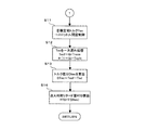
図3は、前記目標回転速度演算部212における目標回転速度の演算のフローを示す。
ステップ(図ではSと記す。以下同様)1では、水温センサ23で検出された水温Twが回転同期制御作動水温下限値Twlmt1より高いかを判定する。前記回転同期制御作動水温下限値Twlmt1は、該下限値Twlmt1以下の低水温時は、暖機促進のため排気温度上昇用の点火時期リタード制御を行っていることがあるので、回転同期制御時に目標トルクを急激に低下させるときの点火時期リタード制御を行えない(リタード余裕代が少ない)ような値に設定されている。
FIG. 3 shows a flow of calculation of the target rotation speed in the target rotation
In step (denoted as S in the figure, the same applies hereinafter) 1, it is determined whether the water temperature Tw detected by the
ステップ1で、水温Twが回転同期制御作動水温下限値Twlmt1より高いと判定されたときは、ステップ2へ進み、同じく水温Twが回転同期制御作動水温上限値Twlmt2より低いかを判定する。前記回転同期制御作動水温上限値Twlmt2は、該上限値Twlmt2以上の高水温時は、点火時期リタード制御を行うと、暖機が過剰となってオーバーヒートする可能性があるので、やはり、点火時期リタード制御を行えないような値に設定されている。
When it is determined in
ステップ2で水温Twが上限値Twlmt2未満と判定されたとき、つまり、水温Twが、Twlmt1<Tw<Twlmt2の適正温度範囲にあると判定されたときは、ステップ3へ進んで回転同期禁止フラグINHを0とする。
また、水温Twが下限値Twlmt1以下か、上限値Twlmt2以上と判定されたときは、ステップ4へ進んで、回転同期禁止フラグINHを1にセットして、回転同期制御の実行を禁止する。
When it is determined in
On the other hand, when it is determined that the water temperature Tw is lower than the lower limit value Twlmt1 or higher than the upper limit value Twlmt2, the routine proceeds to
ステップ5では、前記回転同期禁止フラグINHの信号を、ATCU12Bに送信する。
ステップ6では、回転同期要求中であるかを判定し、要求中と判定された場合は、ステップ7へ進んで、前記回転同期禁止フラグINHが0であるかを判定し、0と判定されたときは、回転同期制御を実行できると判断し、ステップ8へ進んで回転同期要求トルクTrevを算出する。
In
In
ここで、回転同期制御によってエンジン回転速度Neが変速後の回転速度に略同期し、該同期速度を維持できるだけのトルクに急減させるときのため、過渡時回転同期要求トルクTrevdを、定常時の回転同期要求トルクTrevsとは別に算出する。具体的には、定常時回転同期要求トルクの回転速度上昇用の要求トルクから同期回転速度維持用の要求トルクへのステップ的な変化に対し、所定の速度(変化量の所定割合)で減少するように過渡時回転同期要求トルクTrevdを算出する。なお、上記の算出方式により定常時には、過渡時回転同期要求トルクTrevd=定常時回転同期要求トルクTrevsとなる。 Here, the engine rotation speed Ne is substantially synchronized with the rotation speed after the shift by the rotation synchronization control, and the transient rotation synchronization request torque Trevd is changed to the rotation at the steady state in order to rapidly reduce the torque to a torque that can maintain the synchronization speed. It is calculated separately from the synchronization request torque Trevs. Specifically, it decreases at a predetermined speed (a predetermined ratio of the change amount) with respect to a step change from the required torque for increasing the rotational speed to the required torque for maintaining the synchronous rotational speed. Thus, the rotation-synchronized request torque Trevd during transition is calculated. Note that, in the steady state by the above calculation method, the transient rotation synchronization request torque Trevd = the steady rotation synchronization request torque Trevs.
ステップ9では、前記過渡時の回転同期要求トルクTrevdを目標過渡トルクTedとしてセットし、定常時回転同期要求トルクTrevsを目標定常トルクTesとしてセットする(定常時は、Ted=Tes=Trevs)。
一方、ステップ6,7で回転同期要求中でないと判定されたとき、または、回転同期禁止フラグINHが1で回転同期を禁止すると判定されたときは、ステップ10へ進んでアクセル開度APOに基づいてドライバ要求トルクTapoを算出し、算出したドライバ要求トルクTapoを、過渡時には目標過渡トルクTedとしてセットし、定常時には目標定常トルクTesとしてセットする。
In
On the other hand, when it is determined in
そして、ステップ11では、前記目標定常トルクTesとエンジン回転速度Neとに基づいて目標スロットル開度TVOをマップから参照して算出し、該目標スロットル開度TVOとなるようにスロットル弁開度を制御する。
ステップ12では、定常時回転同期要求トルクTrevsを次式のように一時遅れ処理処理して、過渡時のスロットル開度制御における吸入空気量の遅れに伴う実トルクTesfを算出する。
In step 11, the target throttle opening TVO is calculated from the map based on the target steady torque Tes and the engine speed Ne, and the throttle valve opening is controlled so as to be the target throttle opening TVO. To do.
In
Tesf=G・Trevs+(1−G)・Tresfz
Tesf:一時遅れ処理後定常トルク(=実トルク)
Tresfz:Tesfの前回値
ステップ13では、実トルクと目標過渡トルクとの差分DTesを次式のように算出する。
Tesf = G · Trevs + (1-G) · Tresfz
Tesf: Steady torque after temporary delay processing (= actual torque)
Tresfz: Previous value of Tesf In step 13, the difference DTes between the actual torque and the target transient torque is calculated as follows.
DTes=Tesf−Ted
ここで、実質的に差分DTesを生じるのは、上述した回転同期制御中に、略同期速度に達したと判断されたタイミングでトルクを急減させるときに、過渡時回転同期要求トルクTrevdを目標過渡トルクTedとして算出するときと、回転同期要求フラグが0となって、回転同期制御が終了し、目標トルクが同期回転速度を維持する定常時回転同期要求トルクTrevsからアクセル開度0相当の負のドライバ要求トルクTedにステップ的に減少するときである。
DTes = Tesf-Ted
Here, the difference DTes is substantially generated when the torque is suddenly reduced at the timing when it is determined that the substantially synchronized speed is reached during the above-described rotation synchronization control, and the transient rotation synchronization request torque Trevd is set to the target transient. When calculating as the torque Ted, the rotation synchronization request flag becomes 0, the rotation synchronization control is terminated, and the target torque is a negative value corresponding to the accelerator opening 0 from the steady rotation synchronization request torque Trevs that maintains the synchronous rotation speed. This is the time when the driver request torque Ted decreases stepwise.
これらの時は、目標トルクの急減に応じてスロットル開度を急減する制御を行っただけでは、吸入空気量の応答遅れによって実トルクを目標トルクとおりに急減することができない。
そこで、ステップ14で前記トルクの差分DTesに応じた点火時期リタード量RTDを算出し、点火時期を該リタード量RTDだけリタードする。
In these cases, the actual torque cannot be rapidly reduced according to the target torque due to the response delay of the intake air amount only by performing the control for rapidly decreasing the throttle opening according to the sudden decrease of the target torque.
Therefore, in step 14, an ignition timing retard amount RTD corresponding to the torque difference DTes is calculated, and the ignition timing is retarded by the retard amount RTD.
図4は、回転同期制御時(前後を含む)の各種状態量の変化の様子を示す。図4を参照しつつ、一連の制御について説明する。
回転同期要求フラグが1となって、変速前のクラッチが開放操作されると同時に回転同期制御が開始され、スロットル開度が増大されエンジン回転速度Neが増大する。このときも吸入空気量の増大の応答遅れがあるので、トルクアップに遅れを生じるが、前記特許文献1に記載されたように、スロットル開度をより大きめに制御しつつ点火時期をリタードする制御を併用すれば、エンジン回転速度Neをオーバーシュートを抑制しながら短時間で変速後の同期回転速度まで増大することができる。
FIG. 4 shows how various state quantities change during rotation synchronization control (including before and after). A series of controls will be described with reference to FIG.
The rotation synchronization request flag is set to 1, and the rotation synchronization control is started simultaneously with the release operation of the clutch before shifting, the throttle opening is increased, and the engine rotation speed Ne is increased. At this time as well, there is a response delay due to an increase in the intake air amount, which causes a delay in torque increase. However, as described in
そして、エンジン回転速度Neが略変速後の同期回転速度まで増大し、かつ、変速前のクラッチの開放が完了したと判定されるタイミングで、変速後のギア位置に対応するクラッチの結合操作を開始し、結合され始めた時点で定常時回転同期要求トルクTrevsが前記同期回転速度まで増大させるためのトルクから該同期回転速度を維持するためのトルクに切り換えられる。このとき所定の速度で減少するように過渡時回転同期要求トルクTrevdが実質的な目標トルク(目標過渡トルク)として算出される。 Then, at the timing when it is determined that the engine rotational speed Ne increases to the synchronous rotational speed after the substantial shift and the release of the clutch before the shift is completed, the clutch coupling operation corresponding to the gear position after the shift is started. Then, at the time of starting to be coupled, the steady-state rotation synchronization request torque Trevs is switched from the torque for increasing the synchronization rotation speed to the torque for maintaining the synchronization rotation speed. At this time, the transient rotation synchronization required torque Trevd is calculated as a substantial target torque (target transient torque) so as to decrease at a predetermined speed.
上記のように、ステップ的に減少する定常時回転同期要求トルクTrevsに応じてスロットル開度をステップ的に減少制御したときの吸入空気量の減少遅れに伴い、遅れを伴って減少する実トルクを、定常時回転同期要求トルクTrevsを一時遅れ処理(加重平均演算)して算出する。
また、回転同期制御終了時には、目標トルクが同期回転速度を維持する定常時回転同期要求トルクTrevsから負のドライバ要求トルクTes(=Ted)にステップ的に減少し、この場合も同様にスロットル開度をステップ的に減少制御したときの吸入空気量の減少遅れに伴い、遅れを伴って減少する実トルクを、定常時回転同期要求トルクTrevsを一時遅れ処理(加重平均演算)して算出する。
As described above, the actual torque that decreases with a delay due to the decrease in intake air amount when the throttle opening is controlled to decrease in a stepwise manner according to the steady-state rotation synchronization request torque Trevs that decreases in a stepwise manner. The steady-state rotation synchronization request torque Trevs is calculated by a temporary delay process (weighted average calculation).
At the end of the rotation synchronization control, the target torque decreases stepwise from the steady rotation synchronization request torque Trevs that maintains the synchronous rotation speed to the negative driver request torque Tes (= Ted). The actual torque that decreases with a delay in the intake air amount when the decrease control is performed in a stepwise manner is calculated by temporarily delaying the steady-state rotation synchronization request torque Trevs (weighted average calculation).
そして、上記のようにして算出した実トルクと目標トルク(回転同期制御中の過渡時回転同期要求トルク、回転同期制御終了時のドライバ要求トルク)との差分を点火時期リタードによってトルク減少することで相殺し、過渡時も略目標トルクに沿って制御することで、ダウンシフト時の変速時間短縮効果を確保しつつ、余剰トルクの発生を抑制して変速ショック(突き上げショック)を十分に緩和することができる。 Then, the difference between the actual torque calculated as described above and the target torque (transient rotation request torque at the time of rotation synchronization control, driver request torque at the end of rotation synchronization control) is reduced by ignition timing retard. By offsetting and controlling along the approximate target torque even during transitions, the effect of shortening the shift time during downshifts can be secured, while the generation of surplus torque is suppressed and the shift shock (push-up shock) is sufficiently mitigated. Can do.
また、本実施形態では、水温等により点火時期リタード制御を行えない条件では回転同期制御を禁止する(通常変速制御に切り換える)構成として、変速ショック発生を回避できるが、変速速度(クラッチ結合速度)を油圧増加速度を遅くして減少補正する(通常変速制御時よりは早い)ことで、変速時間をできるだけ短縮しつつクラッチ結合時の変速ショックを緩和する構成とすることもできる。 In the present embodiment, the generation of a shift shock can be avoided as a configuration in which the rotation synchronization control is prohibited (switched to the normal shift control) under the condition that the ignition timing retard control cannot be performed due to the water temperature or the like, but the shift speed (clutch coupling speed) can be avoided. Therefore, it is possible to reduce the shift shock during clutch engagement while shortening the shift time as much as possible.
1…エンジン
3…スロットルモータ
4…スロットル弁
5…自動変速機
12…電子コントロールユニット(ECU)
12A…エンジンコントロールユニット部(EGCU)
12B…ATコントロールユニット部(ATCU)
21…スロットルセンサ
22…アクセル開度センサ
25…ギア位置センサ
26…モードスイッチ
27…シフト位置センサ
28…車速センサ
DESCRIPTION OF
12A ... Engine control unit (EGCU)
12B ... AT control unit (ATCU)
DESCRIPTION OF
Claims (6)
エンジン出力軸に連結された自動変速機のダウンシフト操作時に、エンジン回転速度を変速後のエンジン回転速度に近づけるように、スロットル開度を増大してエンジン出力を増大制御するエンジンの制御装置であって、
前記エンジン出力の増大制御で増加したエンジンの出力トルクをスロットル開度を減少して急減させるときに、実トルクが目標トルクを上回る余剰トルク分を、点火時期のリタード制御によるトルク減少分で相殺することを特徴とするエンジンの制御装置。 Throttle opening control means for controlling the throttle opening to increase or decrease the engine output is provided,
It is an engine control device that increases the engine output by increasing the throttle opening so that the engine rotational speed approaches the engine rotational speed after the shift during a downshift operation of the automatic transmission connected to the engine output shaft. And
When the engine output torque increased by the engine output increase control is rapidly decreased by decreasing the throttle opening, the excess torque exceeding the target torque is offset by the torque decrease by the ignition timing retard control. An engine control device.
Priority Applications (5)
| Application Number | Priority Date | Filing Date | Title |
|---|---|---|---|
| JP2004298137A JP4274100B2 (en) | 2004-10-12 | 2004-10-12 | Engine control device |
| US11/245,432 US7347805B2 (en) | 2004-10-12 | 2005-10-07 | Engine torque control device |
| EP05022156.3A EP1647691B1 (en) | 2004-10-12 | 2005-10-11 | Engine torque control device |
| CNB2005101133694A CN100447391C (en) | 2004-10-12 | 2005-10-11 | Engine torque control device |
| KR1020050095416A KR100713054B1 (en) | 2004-10-12 | 2005-10-11 | Engine torque control device |
Applications Claiming Priority (1)
| Application Number | Priority Date | Filing Date | Title |
|---|---|---|---|
| JP2004298137A JP4274100B2 (en) | 2004-10-12 | 2004-10-12 | Engine control device |
Publications (2)
| Publication Number | Publication Date |
|---|---|
| JP2006112257A JP2006112257A (en) | 2006-04-27 |
| JP4274100B2 true JP4274100B2 (en) | 2009-06-03 |
Family
ID=35520067
Family Applications (1)
| Application Number | Title | Priority Date | Filing Date |
|---|---|---|---|
| JP2004298137A Active JP4274100B2 (en) | 2004-10-12 | 2004-10-12 | Engine control device |
Country Status (5)
| Country | Link |
|---|---|
| US (1) | US7347805B2 (en) |
| EP (1) | EP1647691B1 (en) |
| JP (1) | JP4274100B2 (en) |
| KR (1) | KR100713054B1 (en) |
| CN (1) | CN100447391C (en) |
Families Citing this family (20)
| Publication number | Priority date | Publication date | Assignee | Title |
|---|---|---|---|---|
| JP4169029B2 (en) * | 2005-11-22 | 2008-10-22 | トヨタ自動車株式会社 | Shift control device for automatic transmission for vehicle |
| JP4725450B2 (en) * | 2006-07-31 | 2011-07-13 | トヨタ自動車株式会社 | Control device for automatic transmission |
| KR20080023038A (en) * | 2006-09-08 | 2008-03-12 | 현대자동차주식회사 | Skip down shift control method of automatic transmission on vehicle |
| JP4470954B2 (en) * | 2007-03-16 | 2010-06-02 | トヨタ自動車株式会社 | Vehicle driving force control device |
| DE102008018969A1 (en) * | 2008-04-16 | 2009-01-22 | Daimler Ag | Method for controlling of switch operation involves 3 phases managing the engine moment |
| JP2010052726A (en) * | 2008-08-01 | 2010-03-11 | Yamaha Motor Co Ltd | Transmission control system and vehicle |
| JP4816813B2 (en) * | 2008-10-31 | 2011-11-16 | トヨタ自動車株式会社 | Control device for internal combustion engine |
| JP5120273B2 (en) * | 2009-01-22 | 2013-01-16 | トヨタ自動車株式会社 | Control device for internal combustion engine |
| JP5678427B2 (en) * | 2009-11-30 | 2015-03-04 | トヨタ自動車株式会社 | Vehicle control device |
| KR101793075B1 (en) | 2010-12-20 | 2017-11-20 | 콘티넨탈 오토모티브 시스템 주식회사 | Method and apparatus for controlling automatic transmission |
| US8801572B2 (en) | 2011-04-29 | 2014-08-12 | Cnh Industrial America Llc | System and method for synchronizing engine and transmission system operation within an agricultural vehicle |
| CN103814200B (en) * | 2011-09-20 | 2016-08-17 | 丰田自动车株式会社 | The control device of internal combustion engine |
| KR101252773B1 (en) * | 2011-10-31 | 2013-04-09 | 주식회사 현대케피코 | Engine torque control apparatus and method |
| FR2985970B1 (en) * | 2012-01-24 | 2014-03-21 | Peugeot Citroen Automobiles Sa | METHOD FOR DETERMINING THE TORQUE OF A THERMAL ENGINE |
| US20140032057A1 (en) * | 2012-07-24 | 2014-01-30 | Wei Li | Feedforward control system |
| WO2014076822A1 (en) * | 2012-11-16 | 2014-05-22 | トヨタ自動車株式会社 | Vehicle transmission control device |
| US9598065B2 (en) | 2014-10-14 | 2017-03-21 | Honda Motor Co., Ltd. | Internal combustion engine controller, and control system and method of controlling an internal combustion engine |
| KR101744813B1 (en) * | 2015-09-14 | 2017-06-20 | 현대자동차 주식회사 | Method for controlling engine of manual transmission vehicle |
| US10053105B2 (en) * | 2016-01-13 | 2018-08-21 | Cnh Industrial America Llc | Drive mode selection for an autonomous vehicle |
| FR3064692B1 (en) * | 2017-04-03 | 2019-04-19 | Peugeot Citroen Automobiles Sa | TORQUE CONTROL METHOD OF A CONTROL IGNITION ENGINE |
Family Cites Families (17)
| Publication number | Priority date | Publication date | Assignee | Title |
|---|---|---|---|---|
| US4686125A (en) | 1984-09-28 | 1987-08-11 | Baxter Travenol Laboratories, Inc. | Film laminate for sterile flexible containers |
| JP2805710B2 (en) * | 1989-09-30 | 1998-09-30 | マツダ株式会社 | Shift shock reduction device for automatic transmission |
| KR920006776B1 (en) * | 1989-11-04 | 1992-08-17 | 현대자동차 주식회사 | Change-speed shock reducing equipment and method of car mounted on automatic change-speed gearing control device |
| JP3316631B2 (en) | 1991-12-12 | 2002-08-19 | 株式会社ユニシアジェックス | Output shaft torque control device for vehicle drive train |
| JPH05302662A (en) * | 1992-04-24 | 1993-11-16 | Aisin Aw Co Ltd | Automatic transmission |
| DE4329007C2 (en) * | 1992-09-04 | 2003-03-27 | Volkswagen Ag | Process for controlling the shifting process in an automatic transmission |
| DE4330194B4 (en) * | 1992-09-17 | 2009-12-17 | Volkswagen Ag | Control method for an automatic transmission |
| JP3445291B2 (en) * | 1992-10-13 | 2003-09-08 | 株式会社日立製作所 | Drive torque control device |
| JP3204140B2 (en) | 1996-07-24 | 2001-09-04 | トヨタ自動車株式会社 | Vehicle output control device |
| GB9617956D0 (en) | 1996-08-28 | 1996-10-09 | Eaton Corp | Downshift control method/system for vehicular automated mechanical transmission |
| JP3440774B2 (en) * | 1997-08-12 | 2003-08-25 | 日産自動車株式会社 | Transmission control device for continuously variable transmission |
| DE19856326A1 (en) | 1998-12-07 | 2000-06-08 | Zahnradfabrik Friedrichshafen | Method for controlling an automatic transmission |
| DE10006264C1 (en) * | 2000-02-12 | 2001-08-16 | Bosch Gmbh Robert | Internal combustion engine and method for operating an internal combustion engine |
| JP3709787B2 (en) * | 2000-12-20 | 2005-10-26 | 日産自動車株式会社 | Torque down control device during shifting |
| JP2002221068A (en) * | 2001-01-26 | 2002-08-09 | Denso Corp | Torque control device of internal combustion engine |
| US7131933B2 (en) * | 2001-12-07 | 2006-11-07 | Toyota Jidosha Kabushiki Kaisha | Vehicle control apparatus having means for changing inertia torque of engine during shifting action or during switching of operating state of lock-up clutch |
| JP4306597B2 (en) * | 2004-02-25 | 2009-08-05 | トヨタ自動車株式会社 | Control device for vehicle drive device |
-
2004
- 2004-10-12 JP JP2004298137A patent/JP4274100B2/en active Active
-
2005
- 2005-10-07 US US11/245,432 patent/US7347805B2/en active Active
- 2005-10-11 CN CNB2005101133694A patent/CN100447391C/en active Active
- 2005-10-11 EP EP05022156.3A patent/EP1647691B1/en active Active
- 2005-10-11 KR KR1020050095416A patent/KR100713054B1/en active IP Right Grant
Also Published As
| Publication number | Publication date |
|---|---|
| KR20060052175A (en) | 2006-05-19 |
| EP1647691B1 (en) | 2017-01-18 |
| US7347805B2 (en) | 2008-03-25 |
| CN100447391C (en) | 2008-12-31 |
| EP1647691A2 (en) | 2006-04-19 |
| JP2006112257A (en) | 2006-04-27 |
| US20060079374A1 (en) | 2006-04-13 |
| KR100713054B1 (en) | 2007-05-02 |
| EP1647691A3 (en) | 2012-06-06 |
| CN1760522A (en) | 2006-04-19 |
Similar Documents
| Publication | Publication Date | Title |
|---|---|---|
| JP4274100B2 (en) | Engine control device | |
| JP4389748B2 (en) | Engine control device | |
| JP2006112255A (en) | Engine control device | |
| JP2007270825A (en) | Vehicle power train control apparatus | |
| JP4281767B2 (en) | Vehicle control device | |
| JP2006112256A (en) | Engine control device | |
| JP4743289B2 (en) | Control device for vehicle drive device | |
| JP4301021B2 (en) | Engine control device | |
| JP2008045565A (en) | Vehicle control device | |
| JP4893405B2 (en) | Vehicle control apparatus, control method, program for realizing the method, and recording medium recording the program | |
| JP2007327477A (en) | Control device of automatic transmission | |
| KR100901677B1 (en) | Control apparatus for vehicle and method of controlling vehicle | |
| JP2002147599A (en) | Damper clutch release control method for automatic transmission | |
| JP2008157190A (en) | Control device for engine | |
| JP2010249190A (en) | Control device of automatic transmission for vehicle | |
| JP4078940B2 (en) | Engine control device | |
| JP2005133895A (en) | Automatic transmission control device | |
| JP4281766B2 (en) | Vehicle control device | |
| JP3417715B2 (en) | Powertrain controls | |
| JP2005090339A (en) | Power generation amount controller for generator for vehicle | |
| JP2006273016A (en) | Vehicular control device | |
| JPH04241773A (en) | Device for setting and controlling output shaft torque of automatic transmission | |
| JP2982926B2 (en) | Automatic transmission pull-in state determination device and hydraulic control device | |
| JP4946999B2 (en) | Vehicle control device | |
| JP2008014421A (en) | Automatic transmission control device |
Legal Events
| Date | Code | Title | Description |
|---|---|---|---|
| A621 | Written request for application examination |
Free format text: JAPANESE INTERMEDIATE CODE: A621 Effective date: 20070925 |
|
| RD03 | Notification of appointment of power of attorney |
Free format text: JAPANESE INTERMEDIATE CODE: A7423 Effective date: 20080321 |
|
| RD04 | Notification of resignation of power of attorney |
Free format text: JAPANESE INTERMEDIATE CODE: A7424 Effective date: 20080331 |
|
| A871 | Explanation of circumstances concerning accelerated examination |
Free format text: JAPANESE INTERMEDIATE CODE: A871 Effective date: 20081009 |
|
| A975 | Report on accelerated examination |
Free format text: JAPANESE INTERMEDIATE CODE: A971005 Effective date: 20081107 |
|
| A131 | Notification of reasons for refusal |
Free format text: JAPANESE INTERMEDIATE CODE: A131 Effective date: 20081118 |
|
| A521 | Written amendment |
Free format text: JAPANESE INTERMEDIATE CODE: A523 Effective date: 20090115 |
|
| TRDD | Decision of grant or rejection written | ||
| A01 | Written decision to grant a patent or to grant a registration (utility model) |
Free format text: JAPANESE INTERMEDIATE CODE: A01 Effective date: 20090210 |
|
| A01 | Written decision to grant a patent or to grant a registration (utility model) |
Free format text: JAPANESE INTERMEDIATE CODE: A01 |
|
| A61 | First payment of annual fees (during grant procedure) |
Free format text: JAPANESE INTERMEDIATE CODE: A61 Effective date: 20090223 |
|
| R150 | Certificate of patent or registration of utility model |
Ref document number: 4274100 Country of ref document: JP Free format text: JAPANESE INTERMEDIATE CODE: R150 Free format text: JAPANESE INTERMEDIATE CODE: R150 |
|
| FPAY | Renewal fee payment (event date is renewal date of database) |
Free format text: PAYMENT UNTIL: 20120313 Year of fee payment: 3 |
|
| FPAY | Renewal fee payment (event date is renewal date of database) |
Free format text: PAYMENT UNTIL: 20120313 Year of fee payment: 3 |
|
| FPAY | Renewal fee payment (event date is renewal date of database) |
Free format text: PAYMENT UNTIL: 20130313 Year of fee payment: 4 |
|
| FPAY | Renewal fee payment (event date is renewal date of database) |
Free format text: PAYMENT UNTIL: 20130313 Year of fee payment: 4 |