JP4273207B2 - Method and apparatus for encoding or decoding digital video data - Google Patents
Method and apparatus for encoding or decoding digital video data Download PDFInfo
- Publication number
- JP4273207B2 JP4273207B2 JP53057297A JP53057297A JP4273207B2 JP 4273207 B2 JP4273207 B2 JP 4273207B2 JP 53057297 A JP53057297 A JP 53057297A JP 53057297 A JP53057297 A JP 53057297A JP 4273207 B2 JP4273207 B2 JP 4273207B2
- Authority
- JP
- Japan
- Prior art keywords
- bit rate
- storage capacity
- encoding
- average bit
- predetermined storage
- Prior art date
- Legal status (The legal status is an assumption and is not a legal conclusion. Google has not performed a legal analysis and makes no representation as to the accuracy of the status listed.)
- Expired - Lifetime
Links
- 238000000034 method Methods 0.000 title claims abstract description 23
- 238000013139 quantization Methods 0.000 claims description 52
- 230000003287 optical effect Effects 0.000 claims description 4
- 238000011217 control strategy Methods 0.000 abstract description 3
- 230000008569 process Effects 0.000 abstract description 2
- 239000000872 buffer Substances 0.000 description 63
- 238000004364 calculation method Methods 0.000 description 7
- 230000008859 change Effects 0.000 description 7
- 238000013500 data storage Methods 0.000 description 7
- 238000006243 chemical reaction Methods 0.000 description 6
- 230000007704 transition Effects 0.000 description 5
- 238000010586 diagram Methods 0.000 description 4
- 230000000007 visual effect Effects 0.000 description 4
- 230000008901 benefit Effects 0.000 description 3
- 101000604746 Arabidopsis thaliana 2-succinyl-6-hydroxy-2,4-cyclohexadiene-1-carboxylate synthase Proteins 0.000 description 2
- 101000969688 Homo sapiens Macrophage-expressed gene 1 protein Proteins 0.000 description 2
- 102100021285 Macrophage-expressed gene 1 protein Human genes 0.000 description 2
- 238000013459 approach Methods 0.000 description 2
- 230000007423 decrease Effects 0.000 description 2
- 230000001419 dependent effect Effects 0.000 description 2
- MJEMIOXXNCZZFK-UHFFFAOYSA-N ethylone Chemical compound CCNC(C)C(=O)C1=CC=C2OCOC2=C1 MJEMIOXXNCZZFK-UHFFFAOYSA-N 0.000 description 2
- 239000000463 material Substances 0.000 description 2
- 230000004044 response Effects 0.000 description 2
- 102100037812 Medium-wave-sensitive opsin 1 Human genes 0.000 description 1
- 230000006978 adaptation Effects 0.000 description 1
- 230000003044 adaptive effect Effects 0.000 description 1
- 230000006399 behavior Effects 0.000 description 1
- 230000005540 biological transmission Effects 0.000 description 1
- 230000003139 buffering effect Effects 0.000 description 1
- 230000003111 delayed effect Effects 0.000 description 1
- 230000000694 effects Effects 0.000 description 1
- 230000006870 function Effects 0.000 description 1
- 238000013507 mapping Methods 0.000 description 1
- 238000005259 measurement Methods 0.000 description 1
- 238000005192 partition Methods 0.000 description 1
- 238000012545 processing Methods 0.000 description 1
- 230000000750 progressive effect Effects 0.000 description 1
Images


Classifications
-
- H—ELECTRICITY
- H04—ELECTRIC COMMUNICATION TECHNIQUE
- H04N—PICTORIAL COMMUNICATION, e.g. TELEVISION
- H04N19/00—Methods or arrangements for coding, decoding, compressing or decompressing digital video signals
- H04N19/10—Methods or arrangements for coding, decoding, compressing or decompressing digital video signals using adaptive coding
- H04N19/169—Methods or arrangements for coding, decoding, compressing or decompressing digital video signals using adaptive coding characterised by the coding unit, i.e. the structural portion or semantic portion of the video signal being the object or the subject of the adaptive coding
- H04N19/177—Methods or arrangements for coding, decoding, compressing or decompressing digital video signals using adaptive coding characterised by the coding unit, i.e. the structural portion or semantic portion of the video signal being the object or the subject of the adaptive coding the unit being a group of pictures [GOP]
-
- H—ELECTRICITY
- H04—ELECTRIC COMMUNICATION TECHNIQUE
- H04N—PICTORIAL COMMUNICATION, e.g. TELEVISION
- H04N5/00—Details of television systems
- H04N5/76—Television signal recording
- H04N5/91—Television signal processing therefor
- H04N5/92—Transformation of the television signal for recording, e.g. modulation, frequency changing; Inverse transformation for playback
-
- H—ELECTRICITY
- H04—ELECTRIC COMMUNICATION TECHNIQUE
- H04N—PICTORIAL COMMUNICATION, e.g. TELEVISION
- H04N19/00—Methods or arrangements for coding, decoding, compressing or decompressing digital video signals
- H04N19/10—Methods or arrangements for coding, decoding, compressing or decompressing digital video signals using adaptive coding
- H04N19/102—Methods or arrangements for coding, decoding, compressing or decompressing digital video signals using adaptive coding characterised by the element, parameter or selection affected or controlled by the adaptive coding
- H04N19/115—Selection of the code volume for a coding unit prior to coding
-
- H—ELECTRICITY
- H04—ELECTRIC COMMUNICATION TECHNIQUE
- H04N—PICTORIAL COMMUNICATION, e.g. TELEVISION
- H04N19/00—Methods or arrangements for coding, decoding, compressing or decompressing digital video signals
- H04N19/10—Methods or arrangements for coding, decoding, compressing or decompressing digital video signals using adaptive coding
- H04N19/102—Methods or arrangements for coding, decoding, compressing or decompressing digital video signals using adaptive coding characterised by the element, parameter or selection affected or controlled by the adaptive coding
- H04N19/124—Quantisation
- H04N19/126—Details of normalisation or weighting functions, e.g. normalisation matrices or variable uniform quantisers
-
- H—ELECTRICITY
- H04—ELECTRIC COMMUNICATION TECHNIQUE
- H04N—PICTORIAL COMMUNICATION, e.g. TELEVISION
- H04N19/00—Methods or arrangements for coding, decoding, compressing or decompressing digital video signals
- H04N19/10—Methods or arrangements for coding, decoding, compressing or decompressing digital video signals using adaptive coding
- H04N19/134—Methods or arrangements for coding, decoding, compressing or decompressing digital video signals using adaptive coding characterised by the element, parameter or criterion affecting or controlling the adaptive coding
- H04N19/136—Incoming video signal characteristics or properties
- H04N19/137—Motion inside a coding unit, e.g. average field, frame or block difference
-
- H—ELECTRICITY
- H04—ELECTRIC COMMUNICATION TECHNIQUE
- H04N—PICTORIAL COMMUNICATION, e.g. TELEVISION
- H04N19/00—Methods or arrangements for coding, decoding, compressing or decompressing digital video signals
- H04N19/10—Methods or arrangements for coding, decoding, compressing or decompressing digital video signals using adaptive coding
- H04N19/134—Methods or arrangements for coding, decoding, compressing or decompressing digital video signals using adaptive coding characterised by the element, parameter or criterion affecting or controlling the adaptive coding
- H04N19/136—Incoming video signal characteristics or properties
- H04N19/14—Coding unit complexity, e.g. amount of activity or edge presence estimation
-
- H—ELECTRICITY
- H04—ELECTRIC COMMUNICATION TECHNIQUE
- H04N—PICTORIAL COMMUNICATION, e.g. TELEVISION
- H04N19/00—Methods or arrangements for coding, decoding, compressing or decompressing digital video signals
- H04N19/10—Methods or arrangements for coding, decoding, compressing or decompressing digital video signals using adaptive coding
- H04N19/134—Methods or arrangements for coding, decoding, compressing or decompressing digital video signals using adaptive coding characterised by the element, parameter or criterion affecting or controlling the adaptive coding
- H04N19/146—Data rate or code amount at the encoder output
- H04N19/147—Data rate or code amount at the encoder output according to rate distortion criteria
-
- H—ELECTRICITY
- H04—ELECTRIC COMMUNICATION TECHNIQUE
- H04N—PICTORIAL COMMUNICATION, e.g. TELEVISION
- H04N19/00—Methods or arrangements for coding, decoding, compressing or decompressing digital video signals
- H04N19/10—Methods or arrangements for coding, decoding, compressing or decompressing digital video signals using adaptive coding
- H04N19/134—Methods or arrangements for coding, decoding, compressing or decompressing digital video signals using adaptive coding characterised by the element, parameter or criterion affecting or controlling the adaptive coding
- H04N19/146—Data rate or code amount at the encoder output
- H04N19/152—Data rate or code amount at the encoder output by measuring the fullness of the transmission buffer
-
- H—ELECTRICITY
- H04—ELECTRIC COMMUNICATION TECHNIQUE
- H04N—PICTORIAL COMMUNICATION, e.g. TELEVISION
- H04N19/00—Methods or arrangements for coding, decoding, compressing or decompressing digital video signals
- H04N19/10—Methods or arrangements for coding, decoding, compressing or decompressing digital video signals using adaptive coding
- H04N19/134—Methods or arrangements for coding, decoding, compressing or decompressing digital video signals using adaptive coding characterised by the element, parameter or criterion affecting or controlling the adaptive coding
- H04N19/157—Assigned coding mode, i.e. the coding mode being predefined or preselected to be further used for selection of another element or parameter
- H04N19/159—Prediction type, e.g. intra-frame, inter-frame or bidirectional frame prediction
-
- H—ELECTRICITY
- H04—ELECTRIC COMMUNICATION TECHNIQUE
- H04N—PICTORIAL COMMUNICATION, e.g. TELEVISION
- H04N19/00—Methods or arrangements for coding, decoding, compressing or decompressing digital video signals
- H04N19/10—Methods or arrangements for coding, decoding, compressing or decompressing digital video signals using adaptive coding
- H04N19/169—Methods or arrangements for coding, decoding, compressing or decompressing digital video signals using adaptive coding characterised by the coding unit, i.e. the structural portion or semantic portion of the video signal being the object or the subject of the adaptive coding
- H04N19/17—Methods or arrangements for coding, decoding, compressing or decompressing digital video signals using adaptive coding characterised by the coding unit, i.e. the structural portion or semantic portion of the video signal being the object or the subject of the adaptive coding the unit being an image region, e.g. an object
- H04N19/172—Methods or arrangements for coding, decoding, compressing or decompressing digital video signals using adaptive coding characterised by the coding unit, i.e. the structural portion or semantic portion of the video signal being the object or the subject of the adaptive coding the unit being an image region, e.g. an object the region being a picture, frame or field
-
- H—ELECTRICITY
- H04—ELECTRIC COMMUNICATION TECHNIQUE
- H04N—PICTORIAL COMMUNICATION, e.g. TELEVISION
- H04N19/00—Methods or arrangements for coding, decoding, compressing or decompressing digital video signals
- H04N19/50—Methods or arrangements for coding, decoding, compressing or decompressing digital video signals using predictive coding
-
- H—ELECTRICITY
- H04—ELECTRIC COMMUNICATION TECHNIQUE
- H04N—PICTORIAL COMMUNICATION, e.g. TELEVISION
- H04N19/00—Methods or arrangements for coding, decoding, compressing or decompressing digital video signals
- H04N19/60—Methods or arrangements for coding, decoding, compressing or decompressing digital video signals using transform coding
- H04N19/61—Methods or arrangements for coding, decoding, compressing or decompressing digital video signals using transform coding in combination with predictive coding
-
- H—ELECTRICITY
- H04—ELECTRIC COMMUNICATION TECHNIQUE
- H04N—PICTORIAL COMMUNICATION, e.g. TELEVISION
- H04N19/00—Methods or arrangements for coding, decoding, compressing or decompressing digital video signals
- H04N19/10—Methods or arrangements for coding, decoding, compressing or decompressing digital video signals using adaptive coding
- H04N19/134—Methods or arrangements for coding, decoding, compressing or decompressing digital video signals using adaptive coding characterised by the element, parameter or criterion affecting or controlling the adaptive coding
- H04N19/146—Data rate or code amount at the encoder output
Abstract
Description
本発明は、一定のデータ記憶容量を有する記憶媒体のためディジタルビデオデータを符号化し、一定のデータ記憶容量を有する記憶媒体からのディジタルビデオデータを復号化する方法並びに装置に関する。
発明の背景
ISO/IEC 13818″Information Technology-Generic coding of moving pictures and associated audio information:Video″(MPEG2)には、符号化ディジタルビデオ及びオーディオデータストリームに関する国際標準が記載されている。画像内容の変化に起因して、生成されるコードの量は時間に関して変化する。しかし、固定チャネル容量の場合、一般的に、送信側でエンコーダバッファを使用し、受信側でデコーダバッファを使用することにより実現され得る固定ビットレート(CBR)MPEGエンコーダコントロールが望ましい。これについては、上記国際標準の付属書類C及びD.4に詳細に説明されている。他のモードは可変ビットレート(VBR)符号化である。
発明の概要
可変ビットレート動作が可能であるDVD(ディジタルビデオディスク)のようなディジタル記憶媒体が存在する場合、固定ビットレート符号化の代わりに可変ビットレート符号化を使用することにより符号化品質を改良することが可能である。
本発明の目的は、符号化品質が固定ビットレート符号化の場合の品質よりも基本的に改良される、固定容量記憶媒体のための可変ビットレート符号化の方法を開示することである。本発明の目的は請求項1に記載された方法によって実現される。
本発明の別の目的は、復号化品質が固定ビットレート復号化の場合の品質よりも基本的に改良される、固定容量記憶媒体からの可変ビットレート復号化の方法を開示することである。この目的は請求項2に記載された方法によって実現される。
本発明の別の目的は、上記の新規の符号化及び復号化方法を夫々に使用する符号化及び復号化装置を提供することである。この目的は請求項3及び4に記載された装置によって実現される。
本発明の別の目的は、上記本発明の方法に従って符号化又は復号化されるディジタルビデオ信号を開示することである。この目的は請求項5に記載された信号によって実現される。
“固定ビットレート”は、各フィールド期間(50Hzテレビジョン信号の場合には20ms)に一定数のビットがチャネル(例えば、システムマルチプレクサ)に出力されることを意味し、一方、“可変ビットレート”は、他の全てのビット送出スケジュールをカバーする。
固定ビットレート環境において、カーネルMPEGエンコーダ回路の後にある程度のサイズのバッファが接続される。このバッファはカーネルMPEGエンコーダの本質的に可変性のビットレート出力を平滑化する。ビデオバッファリング照合子VBVは、使用可能なエンコーダバッファサイズの上限、並びに、このプロファイル@レベル(P@L)に準拠した全てのビットストリームを復号化するためデコーダによって必要とされる最小バッファサイズを与えるエンコーダコントロールにおいて使用される概念である。全ての定義されたプロファイル@レベル(P@L)に対し、最大VBVバッファサイズ値は、ISO/IEC 13818-2の第8節に指定されている。より小さい値も許容され、VBVバッファサイズエレメントによって各ビットストリーム中でシグナリングされ得る。
可変ビットレートアプリケーションにおいて、ビットレートを平滑化するためエンコーダバッファを使用する切迫した必要性はないが、以下の説明から明らかになるように、バッファを確保することが有用である。変更点は、チャネルビットレートが可変になることである。
固定ビットレート及び可変ビットレートの両方のアプリケーションにおいて、MPEGエンコーダ及びMPEGデコーダは周知のハイブリッドDPCM/DCT構造を使用することにより動作する。
可変ビットレートデータストリームを処理する能力のある記憶装置を使用するアプリケーションのためのビットレート制御の目的は、固定ビットレートの場合とは相違する。望ましくは、
・時間に関して均一な品質を維持し、
・所定の容量の媒体上で記憶時間を最大限に延ばすべきである。
従って、エンコーダ制御戦略はこの状況に適合されるべきである。
このエンコーダ制御の理解を助けるため、最初に固定ビットレートに対するエンコーダ制御を説明する。
従来のエンコーダ制御戦略は3段階又は制御レベルを含む。
1)ビット割付(大域的制御)
異なる符号化フレーム対応(I,P,Bフレーム)へのビットの割付は、相対的な複雑さXi,Xp,Xbに従って決められる。その目標は、フレームタイプの主観的な品質を一致させることである。事前解析を行わない以下のフィードバック実装の場合、ビデオシーンはある時間に亘って十分に静止していると考えられるので、過去のフレームからの情報は次のフレーム又はフィールドのビット割付のため使用することができる。以下の説明において、用語“フレーム”は、一般的に、フレーム若しくはフィールド、又は、(以下に定義される)ユニットよりも大きいGOP(グループオブピクチャ)の他のセクションを示す。
複雑さは、所定の画質でI、P及びBフレームを符号化する相対的なコストを反映する規準によって評価され得る。しかし、エンコーダの複雑さに負担を掛けすぎることなく、必要な測定量が得られるかどうかを考慮しなければならない。
最初に“画質”が測定されるべきである。しかし、一般的に合意された充分に簡単な客観的な測定規準は存在しないことは周知である。従って、通常、再構成されたフレームのSN比が画質の近似として扱われる。MPEGエンコーダ制御の場合に、この測定規準は、各符号化フレームに対するSN比の計算を含むので幾分コスト高である。従って、その代わりとしてフレームを符号化するため使用された平均量子化ステップサイズ(Qi,Qp,Qb)が品質指標であるとみなされる。“品質”の測定規準が定義されたので、フレームの“複雑さ”は、発生されたビットと使用された量子化ステップの積によって表現され得る。換言すると、フレームの復号化が複雑化するのは、量子化ステップサイズが粗いにもかかわらず、フレームが多数のビットを生成する場合である。この積は各ユニットm(例えば、マクロブロック、ブロック、スライス、又は、フレームよりも小さい任意の区画)に対し形成され、フレーム全体に関して加算される。
xm=bm*qm (1a)
Xc=Σxm (1b)
式中、bmはユニットmを符号化するためのビット数であり、qmはユニットmで使用される平均量子化サイズであり、c=i,p又はbは符号化タイプである。
各グループオブピクチャGOPの先頭で、現在のGOP pに関して利用可能なビットバジェット(ビットの蓄え)BG(g)は、先行のGOPからの繰り上げBG(g−1)も考慮して、
BF(n=0)=BG(g)=(ビットレート)*
(1GOP当たりのフレーム)/(フレームレート)−BG(g−1) (2)
のように表される。現在のGOPの各フレームnに対し、符号化タイプcに依存したビットの目標数Tcは、計算された複雑さ及び現在のGOP内の各符号化タイプの残りのフレーム数(Ni,Np,Nb)に従って決定される。GOPのフレームn−1の符号化後に、残りのビットBF(n)を考慮することにより、以下の式を使用することができる。
Tc=BF(n)*(Xc*Kc)/
(Ni*Xi*Ki+Np*Xp*Kp+Nb*Xb*Kb) (3)
係数Kcはフレーム符号化タイプの種々の視覚的重要性を反映するため使用され、典型的にKi=Kp=1かつKb<1である。
式(1a)及び(1b)に従う複雑さの計算は、通常、シーン変化に対する合理的な応答を保証するため、最新のI、P及びBフレームからのデータを用いて、各フレームの後に更新される。GOPの残りのフレームに対するビットバジェット
BF(n+1)=BF(n)−Σbm (4)
は、現在のフレームのため使用されたビット数Σbmを減じた後、各対応の残りのフレーム数にセットされたNi、Np、Nbに関して式(3)を用いて再分配される。
GOPの最後のフレームNを符号化した後、残りのビット
BG(g)=BF(N)
は、次のGOP g+1に繰り越される。
また、長時間の平均ビットレートだけを一定に保ちながら1GOP当たりに不定の量のビットを明示的に許容してもよい。実際上、これは、式(2)を用いてGOPの先頭だけでバジェットを再度埋める代わりに、各フレームの後に、
BF(n)=BF(n−1)−Σbm+(ビットレート)/(フレームレート) (5)
を用いて、ビットバジェットBF(n)を再度埋めることにより実現される。このバジェットは、次に、現在のGOP内の残りのフレームだけではなく、GOP内のI、P及びBフレームの数に従って分配される。GOPの途中でシーン変化が生じた場合に、上記の変更を行う効果として、シーン変化のあるPフレームはより多くのビットを獲得し、品質を改良する。しかし、VBVの使用量及び/又はビットバジェットの減少に起因して、殆どの場合に、次の通常のIフレームは必要なビットを獲得しないので、次のGOPの全体的な品質は低下する。従って、好ましくは、“1GOP当たりに一定のビットバジェッド”概念が固定ビットレートアプリケーションに使用される。
各フレーム毎に最小限のビットバジェットが少なくともオーバーヘッド情報を符号化するため必要である。これは、複雑さの一番少なく、非常に少ないビットしか割り付けられない傾向があるBフレームの場合に最も重要である。固定ビットレートのレート制御は、固定の最小限ビットバジェットを使用してもよいが、必要なオーバーヘッドビットバジェットの評価は過去のフレームに基づいて行われる場合がある。
フレーム(通常はIフレーム)に割付可能な最小限のビット数は、VBVの状態によって制限される。最初に空のエンコーダバッファが与えられた場合に、VBVバッファサイズのビットを上回るビットは単一のフレームで消費され得ない。
2)バッファ制御(局所的制御)
個々のフレーム毎に、ビット生成は、制御理論の比例コントローラに対応したバーチャルバッファ概念を使用して、割り付けられた目標ビット数の範囲内に収まるように制御される。この概念は図5に示されている。バーチャルバッファVBUcは、MPEG2エンコーダMENの各ユニット(マクロブロック)によって発生されたビットbmと、Mが1フレーム当たりのユニット数を表す場合にこのユニットに対する目標の部分tm=Tc/Mとの間の差emが補充される。
一つのフレームタイプについて目標と合致する困難さは他のフレームタイプに伝搬すべきではないので、できる限り異なるサイズVcoを有する独立したバーチャルバッファVBUcがフレーム符号化タイプc=i,p,b毎に使用される。フレームの端におけるバーチャルバッファVBUcの状態dmは同じ符号化タイプの次のフレームにdoとして伝搬する。
dm=do+Σ(bm−tm) (6)
各ユニットmに対し、量子化ステップサイズqmがこのバーチャルバッファのサイズVcoに対する使用量dmから計算手段QCにおいて計算される。
所謂“非線形量子化器”テーブルは(非線形量子化とは称されていないがISO/IEC 13818-2のテーブル7−6を参照のこと)、量子化スケールコード(quantiser_scale_code)用の利用可能な31個の符号語の、実際の量子化ステップサイズqmへの充分に進歩的な非線形マッピングを獲得するため使用される。量子化スケールコードは単純に32*dm/Vcoに設定してもよい。このテーブルによって利用可能な非常に粗い量子化は、バッファが充満状態に近いときに“パニック”状況を処理するため使用され得る。
制御理論では比例コントローラの“反応”パラメータと称されるバーチャルバッファのサイズVcoは、制御のきつさを決定する。そのサイズは、発生されたビットの数が目標からかなり偏る場合に、非常に(場合によってはVBVよりも)大きくすることが可能である。シーン変化が現在のGOPで生じたか否かは先験的には分からないので、大きいバーチャルバッファは、例えば、Pフレームのため使用可能である。シーン変化がある場合、ビット生成は予測できない程高い。しかし、これにより画質が低下するのは、量子化ステップが著しく増加される程度にバーチャルバッファが使用された場合に限られる。
予測できなかった高いビット生成に対する反応はできるだけ遅延され、一方、予測できない低いビット生成は直ちに量子化ステップサイズを減少させる方が有利である。これは、例えば、ユニットmを符号化しているときのバーチャルバッファ使用量dmとフレームの開始時の初期使用量doとの関係に依存する異なる反応パラメータVco、Vdco(即ち、バーチャルバッファサイズ)によって以下の式を用いて実現され得る。

VBVの状態は、バーチャルバッファに基づく制御に加えて、特に、制御が“ゆるい”とき、即ち、バーチャルバッファが大きいとき、監視されるべきである。フレームの目標並びにGOP全体の目標が超えられている間、デコーダ物理バッファを表すVBVは、決してアンダーフロー若しくはオーバーフローしない。
また、MPEGは、ある程度のビット数を上回るユニット(マクロブロック)の頻出を許可しない(ISO/IEC 13818-2のテーブル8−6を参照のこと)。これも同様に監視、制御されるべきである。
3)内容適応的量子化
画像の異なる部分の局所的な複雑さの変化を反映するため、ユニット毎の局所的な複雑さ測定規準が計算される。一般に、測定規準はユニットの輝度ブロックのACエネルギーから得られる。
獲得された複雑さの係数は、先に計算された量子化ステップサイズをある程度、例えば、0.5乃至2.0の範囲内の倍率で修正するため使用される。この最終的な(量子化スケールコードとして符号化された)量子化ステップサイズ情報は、先のユニット(マクロブロック)に対する量子化ステップサイズ情報と異なるときに限りビットストリームで伝送される。この目的は、フレーム内の主観的な品質が一様であるようにビットを分散させることである。人間の視覚系の特性を活用する別のスキームを適用してもよい。
好ましくは、制御レベル3)は、粗い量子化の場合にはビット生成の厳密な制御が行えなくなるので禁止される。
レベル1)のビット割付が成功した場合、レベル2)は主として、フレーム全体を通じて一定のバーチャルバッファ状態、即ち、一定量子化ステップサイズを維持すべきである。
しかし、ビット割付が失敗し、及び/又は、複雑さがフレーム内で非常に不均一に分散される場合があるので、実際上、上記の点は必ずしも完全に真ではない。
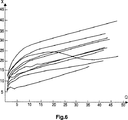
制御スキームの準最適性能の理由は、ステップ1)で計算された複雑さの値は所定の画像に対し一定ではなく、容易にモデル化できない形で量子化ステップサイズに依存することである。これは12個の異なるシーケンスのIフレームについて量子化ステップサイズQに対する複雑さXを表す、図6に示されている。自然な画像シーケンスを符号化するとき、たとえ、シーンが完全に時間的に一様であるとしても、後続のPフレームに対するビット割付にある程度の振動が観察される。適用された量子化ステップサイズとは関係がない複雑さの測定規準が使用される場合、この挙動は回避される利点がある。
可変ビットレートアプリケーションの場合、エンコーダ及びデコーダのバッファから始めて以下の点を更に考慮する必要がある。
上記の如く、物理バッファは可変ビットレートの場合でも有利である。その理由は、他のフレームタイプよりも膨大な量のビットがIフレームによって生成されるからである。例えば、5Mbit/sの固定ビットレートを用いて合理的な品質で標準的なTV画像(CCIR 601解像度)を符号化するとき、“瞬時データレート”が(フレームによって発生されたビット)/(1フレーム期間)により定義される場合に、Iフレーム用の典型的な瞬時データレートは、15Mbit/sよりも高くなり得る。
記憶装置のピークデータレートがこの値よりも低い限り、バッファは、固定ビットレート符号化よりも高い品質を得ることができなければならない。メインプロファイル@メインプロファイル(Main Profile @ Main Profile)に対する1.75Mbit/sのVBVバッファサイズは、例えば、初期に空のバッファを想定するのに充分である45Mbit/sにピーク瞬時データレートを制限する。
エンコーダバッファの可変ビットレート出力及びデコーダバッファの可変ビットレート入力は、漏出しやすいバケツとしてモデル化することができる。データは、常にチャネルのピークレートで漏出する。データはデータがエンコーダバッファ内にある限りエンコーダバッファから漏出し、そのデータはデコーダバッファが一杯ではない限りデコーダバッファに漏入する。
制御目的のため、物理的バッファ状態は1フレーム(フィールド)期間毎に1回だけ監視することができる。しかし、これは、サイズのバッファ部分[(ピークデータレート)/(フレーム期間)]が、フレーム期間中に起こり得る一様ではないビット生成に対処する必要があることを意味する。ユニット毎(マクロブロック毎)に基づくバッファ制御はこの状況を回避するため使用され得る点が有利である。
可変ビットレート制御は以下の目標に到達する必要がある。
始めに仮定されたように、可変ビットレートエンコーダ制御は、記憶媒体上の記録の全区間に亘って品質を一致させることを目標とすべきである。特に、ビットは、付加的(視覚的)な品質の利益が期待できない限り使われるべきではない。レート制御の点から、2通りのシナリオを区別することができる。
シナリオ1)ビデオの最大区間を所定の容量の記憶媒体に合わせる:
十分な品質は制御ステップ2)から量子化ステップサイズを適当な値に設定することによりアプリケーション設計者によって選択され得る。ステップ3)の内容適応的量子化は、各フレーム内で主観的品質の調和を扱うので、依然として行われるべきである。実際上、この領域における改良は、人の観察者によるアーティファクト可視性をよりよく反映する視覚モデルが使用される場合に可能である。
レート制御はエンコーダバッファのオーバーフローを防止するためにのみ必要である。可変チャネルデータレートは一時的に零にすることが許可されるので、オーバーフローは可変ビットレートアプリケーションでは発生しない。
シナリオ1a)保証されたビデオの最小区間:
以下のシナリオ2)に記載されるようなレート制御を用いて、媒体上の最小記録区間を保証することが可能になる。ビデオの複雑さに依存して、記録区間はこの最小値よりも大きくしてもよい。
シナリオ2)所定の容量の媒体上に所定区間のビデオを合わせる:
ビデオ題材を通じて複雑さの分布が先験的に解析されていない場合を想定する。量子化ステップサイズとは無関係であり、かつ、合理的な低コストのエンコーダから入手可能な変数から導き出すことができる利用可能な複雑さの測定規準が存在しない限り、その区間を通じてビデオ品質を一致させる制御解決法はある種の発見的であって最適ではない方法を使用する必要がある。
可変ビットレート制御アプローチの基本的な考え方は、始めからビットレートが変化する非常にゆるい制御を有し、一方、記憶媒体の容量の端に達したとき、又は、予め選択された最小ビットが符号化されるべき画像題材の残りの区間を通じて保証できないようなとき、制御がきつくなることである。
しかし、このアプローチでは、制御の始めを特別に扱うことにより一定の品質を示すことができるが、制御の終わりに向かって品質の低下する可能性がある固定レートが実施されることに注意する必要がある。
この欠点は、記録の終わりに向けて使用される固定ビットレートReが記録全体の平均ビットレートRavgよりも高く選択される場合、ある程度緩和することができる点が有利である。平均ビットレートは、
Ravg=B/T (8)
によって計算することができ、式中、Bは総記憶媒体容量であり、Tはビデオ題材区間である。
このビットレートReは、記録の最初の部分の品質が固定ビットレート符号化によって全体を記録した場合よりも優れている状態を維持されつつ、終わりの方の殆どのビデオ内容が許容可能な品質を示すように選択される方が有利である。
上記の説明から分かるように、各種の記録に対し、未知変数は符号化の開始時の量子化ステップサイズと、終わりの方の固定ビットレートReである。残念ながら、ビデオの複雑さに関する知識がない場合、所定の量子化ステップサイズでのビット生成を評価することは困難であるので、最初に使用する適切な量子化ステップサイズを見つけることは容易に実現できない。
また、全ての時間に物理的バッファ使用量を監視し、一定の量子化から固定レート動作へ移行させる制御スキームを構築することは難しい。この移行は、時点tまでに生成されたビットの量と、未だ符号化されるべき区間とに依存する。初期に著しく多量のビットが生成され、残りの区間が短い場合、きついレート制御が必要であることを意味する。
従って、以下の修正レート制御スキームが提案される。
全記録に亘ってビットレートを制御し続けることが好ましい。非常にゆるい制御(=非常に大きいバーチャルバッファ)を有し、かつ、始めの1GOP当たりの一定ビットバジェットBG(g)を除去することにより、瞬時ビットレート(即ち、準固定量子化ステップサイズ)のかなり大きい変動を許容することが可能になるので、少なくともシーン変化及び数秒の区間の異なるシーンは、このゆるい制御による恩恵をうける。
第1に、記録の最初及び最後における平均ビットレートの合理的な値を定義する必要がある。この記録の平均ビットレートが式(8)に従って計算されたRavgであるとすると、画像シーケンス全体が時間的に一定の複雑さを有する場合、平均ビットレートの0.95倍のビットレートは最悪の場合に無視可能な損失を生じ、一方、最後で平均ビットレートの1.5倍のビットレートは、偶然最後に発生した略最悪の場合の画像内容を十分に適切に符号化し得ることを考慮して、例えば、
Rstart=0.95*Ravg (9a)
Rend=1.5*Ravg (9b)
とするのが有利である。
全時間に亘って(RstartからRendまで直線的に移行する場合)、Ravgは、
Ravg=Rstart*τ1+0.5*(Rstart+Rend)*τ2+Rend*τ3 (10a)
により構成されると考えられ、但し、時間間隔τ1、τ2及びτ3は、
τ1+τ2+τ3=1(記憶媒体の総時間) (10b)
として正規化される。
上記の仮定の場合、もう一つのパラメータを選択する必要がある。τ3を0.01に設定することは、ビット生成全体の精密な制御が非常に短い時間に再確立され得ることを表す。例えば、1時間のビデオ区間Tの場合、τ3*T=36秒に対応する。τ3は全体的なビット数適応期間であるとみなし得る。式(9a)乃至(10b)を解くことにより、
τ1=0.79かつτ2=0.20
が得られる。
上記の数値を用いる場合、ゆるい制御は記録時間の約79%の区間で行われ、一方、移行フェーズは総時間の約20%で生じる。ゆるい制御の時間の割合が増加した別の移行特性を実現することが可能である。
レート制御の時間的変動パラメータは以下の式を用いて記述される。
レート制御のステップ1)で使用されるビットレートは、
R(τ)=(1−α)*Rstart+α・Rend (12)
である。
バーチャルバッファサイズVco、c=i,p,bは、以下の通り修正する方が有利である。
Vc(τ)=((1−α)*Vhuge+α))*Vco (13)
例えば、Vhuge=100のサイズを増加させてもよい。非常に遅い反応に対応するこの巨大なバーチャルバッファは、複雑な画像題材の短い時間間隔を意図している。しかし、長い複雑な部分に続くビデオの複雑ではない部分は、非常に粗い量子化ステップサイズで符号化できることは望ましくない。従って、ビット生成(=バーチャルバッファ状態)が予測以上に減少する場合、即ち、目標よりも低下する場合に、上記のより迅速な反応パラメータの考え方を使用する必要がある。このパラメータVdcは、
Vdc(τ)=((1−α)*Vdhuge+α))*Vdco (14)
に従って時間的に変動するが、この場合、全区間に亘って拘束反応が望ましいので、初期推測値としてVdhuge=1が推奨される。
ビットバジェットBF(n)の再補充は1GOPにつき1回以上行われる。フレームnについての再補充は、
BF(n)=BF(n−1)+(1−α)*R(τ)/(フレームレート)
GOP gについての再補充は、
BF(n=0)=BG(g)=α*R(τ)*(1GOP当たりのフレーム)/(フレームレート)+BG(g−1)
である。
これらは、以下に説明するようにエンコーダバッファ、即ち、漏れやすいバケツとしてのVBVを空にすることとは別に、本明細書の最初のパラグラフで説明したように固定ビットレート制御に対してなされるべき唯一の変更であり得る。
原則として、本発明のディジタルビデオデータを符号化する方法は、所定のデータ記憶容量を有し、可変的な瞬時記憶ビットレートを許容するメモリ又は記録手段上の記憶に適当であり、
−上記記憶容量の前半部分に対し、データは、平均ビットレートよりも僅かに低いビットレートと、平均ビットレート制御よりも著しくゆるい制御とを用いて符号化され、
−上記記憶容量の後半部分に対し、データは、平均ビットレートよりも高いビットレートと、きついビットレート制御とを用いて符号化される。
原則として、本発明の方法は、所定データ記憶容量を有し、復号化バッファ手段への可変的な瞬時読み出しビットレートを許容するメモリ又は記録手段に記憶されたディジタルビデオデータの復号化に適当であり、
−上記記憶容量の前半部分の間に、データは、平均デコーダバッファ手段入力ビットレートよりも僅かに低いビットレートと、平均許容可能バッファ使用量レベル変動よりも著しく高いレベル変動とを用いて復号化され、
−上記記憶容量の後半部分の間に、データは、平均デコーダバッファ手段入力ビットレートよりも高いビットレートと、平均許容可能バッファ使用量レベル変動よりも低いレベル変動とを用いて復号化される。
本発明の方法の有利な更なる実施例は夫々の従属請求項に記載されている。
原則として、本発明の装置は、所定のデータ記憶容量を有し、可変的な瞬時記憶ビットレートを許容するメモリ又は記録手段上の記憶用のディジタルビデオデータの符号化に適当であり、
離散コサイン変換手段と、量子化手段と、逆量子化手段と、逆離散コサイン変換手段と、画像記憶手段と、符号化された出力信号を送出し上記量子化手段の出力に接続されたエントロピー符号化手段とを含む符号化ループを使用し、
上記量子化手段、上記逆量子化手段及び上記エントロピー符号化手段は、
−上記記憶容量の前半部分に対し、データは、平均ビットレートよりも僅かに低いビットレートと、平均ビットレート制御よりも著しくゆるい制御とを用いて符号化され、
−上記記憶容量の後半部分に対し、データは平均ビットレートよりも高いビットレートと、きついビットレート制御とを用いて符号化されるように、制御される。
原則として本発明の装置は、所定のデータ記憶容量を有し、復号化バッファ手段への可変的な瞬時読み出しビットレートを許容するメモリ又は記録手段に記憶されたディジタルビデオデータの復号化に適当であり、
エントロピー復号化手段と、逆量子化手段と、逆離散コサイン変換手段と、画像記憶手段に供給される復号化された出力信号を送出する加算手段とを含み、上記画像記憶手段の出力信号は上記加算手段の第2の入力に供給される回路を使用し、
上記復号化バッファ手段は、
−上記記憶容量の前半部分の間に、データは、平均デコーダバッファ手段入力ビットレートよりも僅かに低いビットレートと、平均許容可能バッファ使用量レベル変動よりも著しく高いレベル変動とを用いて復号化され、
−上記記憶容量の後半部分の間に、データは、平均デコーダバッファ手段入力ビットレートよりも高いビットレートと、平均許容可能バッファ使用量レベル変動よりも低いレベル変動とを用いて復号化されるように制御される。
本発明の装置の有利な更なる実施例は夫々の従属請求項に記載されている。
原則として、本発明のディジタルビデオ信号は、所定のデータ記憶容量を有し、可変的な瞬時記憶ビットレートを許容するメモリ及び記録手段上の記憶に適当であり、
−上記記憶容量の前半部分に対し、上記信号は、平均ビットレートよりも僅かに低いビットレートと、平均ビットレート制御よりも著しくゆるい制御とを用いて符号化され、
−上記記憶容量の後半部分に対し、上記信号は、平均ビットレートよりも高いビットレートと、きついビットレート制御とを用いて符号化される。
好ましくは、本発明のディジタルビデオ信号は、MPEG2若しくはMPEG1、又は、H261に準拠して符号化されたビデオ信号である。
本発明の記憶媒体、特に、光ディスクは、本発明のディジタルビデオ信号を格納するか、又は、本発明のディジタルビデオ信号が記録されている。
図面の説明
以下、添付図面を参照して本発明の好ましい実施例を説明する。
図面中、
図1は固定ビットレートシステムを表し、
図2は可変ビットレートシステムを表し、
図3はMPEGエンコーダの基本的なブロック図であり、
図4はMPEGデコーダの基本的なブロック図であり、
図5は制御ループの構造を示す図であり、
図6は量子化ステップサイズに対する複雑さの関数の例を表わす図である。
好ましい実施例の説明
固定ビットレート又は可変ビットレートアプリケーションにおいて、MPEG2エンコーダMENCは、エンコーダバッファENCBに中間的に記憶される可変ビットレートデータVBRDを生成する。このバッファの使用量レベルはMPEG2エンコーダMENCの符号化処理を制御するため使用され得る。受信側で、デコーダバッファDECBに中間的に記憶された可変ビットレートデータVBRDは、MPEG2デコーダMDECに供給される。デコーダバッファDECBからの可変ビットレートデータVBRDの読み出しはMPEG2デコーダMDECによって制御される。
図1において、エンコーダバッファENCBは固定ビットレートデータストリームCBRをデコーダバッファDECBに送出する。しかし、図2では、エンコーダバッファENCBは可変ビットレートデータストリームVBRをデコーダバッファDECBに送出する。
図3において、エンコーダビデオデータ入力信号IEは、符号化されるべきマクロブロックデータを含む。イントラフレームデータの場合、減算器SUBは、離散コサイン変換計算手段DCTと量子化手段Qを介して、エンコーダバッファを含むエントロピー符号化手段ECODに上記イントラフレームデータをそのまま伝達する。エントロピー符号化手段ECODはエンコーダビデオデータ出力信号OEを送出する。
インターフレームデータの場合、減算器SUBは、入力信号から予測マクロブロックデータPMDを減算し、離散コサイン変換計算手段DECと量子化手段Qを介して、エントロピー符号化手段ECODに差データを伝達する。量子化手段Qの出力信号は、逆量子化手段Q-1 Eにも供給され、逆量子化手段Q-1 Eの出力信号は、逆離散コサイン変換計算手段DCT-1 Eを介して、再生マクロブロック差データRMDDの形で加算器ADDEに伝達される。加算器ADDEの出力信号はフレームストア及び動き補償手段FS_MC_Eに中間的に記憶され、動き補償手段FS_MC_Eは再生マクロブロックデータRMDDに基づいて動き補償を行い、予測マクロブロックデータPMDを減算器SUB及び加算器ADDEの別の入力に送出する。
量子化手段Q、逆量子化手段Q-1 E及びエントロピー符号化手段ECODは、上記の本発明の方法に従ってエンコーダバッファの使用量レベルによって制御される。また、動き補償手段FS_MC_Eは動き補償を行わない場合もあり得る。
記憶媒体への可変ビットレート出力は、エンコーダバッファから利用可能なデータが存在する場合に、最大可能ビットレートを用いて行うことが可能であり、さもなければ、停止することが可能である。
図4において、デコーダビデオデータ入力信号IDは、デコーダバッファを含むエントロピー復号化手段EDECと、逆量子化手段Q-1 Dと、逆離散コサイン変換計算手段DCT-1 Dとを介して、デコーダビデオデータ出力信号ODを送出する加算器ADDDに伝達される。加算器ADDDの出力信号は、フレームストアに供給され、動き補償手段FS_MC_Dは再生マクロブロックデータに基づいて動き補償を行い、インターフレームマクロブロックデータの場合に、予測マクロブロックデータPMDを加算器ADDDの他方の入力に送出する。イントラフレームマクロブロックデータの場合、加算器ADDDは、逆離散コサイン変換計算手段DCT-1 Dの出力信号をそのまま伝達する。
デコーダ側の逆量子化手段Q-1 D及びエントロピー復号化手段EDECは、エンコーダ側の逆量子化手段Q-1E及びエントロピー符号化手段ECODに対する制御と同様の制御に従って制御される。通常、デコーダ側の動き補償手段FS_MC_Dにおいて、エンコーダ側の動き補償手段FS_MC_Eで使用された動きベクトル情報と同じものが使用される。また、デコーダ側の動き補償手段FS_MC_Dは動き補償を行わなくてもよい。
例えば、シーン変化及び複雑なシーン内容の場合のように、高ビットレート要求の状況に対処するため、デコーダバッファは、好ましくは最大可能ビットレートを用いて記憶媒体から補充される。これは、一般的に、デコーダバッファが一杯ではない場合に行われ、デコーダバッファが一杯である場合には、記憶媒体からのデータはデコーダバッファに記憶されない。代替として、デコーダバッファは、データをメモリ又は記録手段に記憶する際の夫々のビットレートに対応したビットレートで補充してもよい。何れの場合も、デコーダバッファからの読み出しビットレートは符号化する際のビットレートと対応し、即ち、許容され、かつ、場合によっては実際に生ずる平均バッファ使用量レベル変動は、総容量の前半部分(≒80%)の方で大きく、総容量の後半部分(≒20%)の方で小さい。“平均許容可能バッファ使用量レベル変動”は、一部のGOPの長さに関する変動を意味する。
本発明は、ビデオデータを記録するため所定の容量を使用するDVD、他の光学式、光磁気式若しくは光磁性式ディスク、電子式若しくは光学式RAM又はROM、及び、磁気テープシステムのようなあらゆる手段で使用することができる。
本発明は、MPEG2エンコーダ及びデコーダに限定されることはなく、MPEG1(ISO/IEC 11172-2)、H261(ISO/IEC)、並びに、例えば、標準TV、HDTV及びテレビ電話アプリケーションにおける他の符号化及び復号化方式と共に使用することが可能である。The present invention relates to a method and apparatus for encoding digital video data for a storage medium having a constant data storage capacity and decoding digital video data from a storage medium having a constant data storage capacity.
Background of the Invention
ISO / IEC 13818 "Information Technology-Generic coding of moving pictures and associated audio information: Video" (MPEG2) describes an international standard for encoded digital video and audio data streams. Due to changes in image content, the amount of code generated varies over time. However, in the case of fixed channel capacity, a constant bit rate (CBR) MPEG encoder control is generally desirable, which can be realized by using an encoder buffer on the transmitting side and a decoder buffer on the receiving side. This is described in Annexes C and D. of the above international standard. 4 is described in detail. Another mode is variable bit rate (VBR) coding.
Summary of the Invention
If there is a digital storage medium such as a DVD (Digital Video Disc) capable of variable bit rate operation, improve the encoding quality by using variable bit rate encoding instead of constant bit rate encoding Is possible.
The object of the present invention is to disclose a method of variable bit rate coding for a fixed capacity storage medium in which the coding quality is basically improved over the quality in the case of constant bit rate coding. The object of the invention is achieved by a method as claimed in claim 1.
Another object of the present invention is to disclose a method for variable bit rate decoding from a fixed capacity storage medium in which the decoding quality is basically improved over that in the case of constant bit rate decoding. This object is achieved by the method described in claim 2.
Another object of the present invention is to provide an encoding and decoding apparatus that uses the above novel encoding and decoding methods, respectively. This object is achieved by the device as defined in claims 3 and 4.
Another object of the present invention is to disclose a digital video signal which is encoded or decoded according to the method of the present invention described above. This object is achieved by a signal as defined in
“Fixed bit rate” means that a fixed number of bits are output to the channel (eg, system multiplexer) during each field period (20 ms for a 50 Hz television signal), while “variable bit rate” Covers all other bit transmission schedules.
In a constant bit rate environment, a buffer of a certain size is connected after the kernel MPEG encoder circuit. This buffer smooths the inherently variable bit rate output of the kernel MPEG encoder. The video buffering verifier VBV specifies the upper limit on the available encoder buffer size, as well as the minimum buffer size required by the decoder to decode all bitstreams that comply with this profile @ level (P @ L). It is a concept used in the given encoder control. For all defined profile @ levels (P @ L), the maximum VBV buffer size value is specified in clause 8 of ISO / IEC 13818-2. Smaller values are allowed and can be signaled in each bitstream by the VBV buffer size element.
In variable bit rate applications, there is no urgent need to use an encoder buffer to smooth the bit rate, but it is useful to reserve the buffer, as will become apparent from the description below. The change is that the channel bit rate becomes variable.
In both constant bit rate and variable bit rate applications, the MPEG encoder and MPEG decoder operate by using the well-known hybrid DPCM / DCT structure.
The purpose of bit rate control for applications using storage devices capable of processing variable bit rate data streams is different from the case of constant bit rate. Preferably
・ Maintains uniform quality over time,
• The storage time should be maximized on a given capacity of media.
Therefore, the encoder control strategy should be adapted to this situation.
To help understand this encoder control, the encoder control for a fixed bit rate will be described first.
Conventional encoder control strategies include three stages or control levels.
1) Bit assignment (global control)
The assignment of bits to different encoded frame correspondences (I, P, B frames) is relative complexity Xi, Xp, XbIt is decided according to. The goal is to match the subjective quality of the frame type. For the following feedback implementation without pre-analysis, the information from the previous frame is used for bit allocation of the next frame or field because the video scene is considered sufficiently stationary for some time be able to. In the following description, the term “frame” generally refers to a frame or field or other section of a GOP (group of pictures) that is larger than a unit (defined below).
Complexity can be assessed by criteria that reflect the relative cost of encoding I, P and B frames with a given image quality. However, consideration must be given to whether the required measurement is obtained without overloading the complexity of the encoder.
First “image quality” should be measured. However, it is well known that there is no generally agreed objective metric that is simple enough. Therefore, the signal-to-noise ratio of the reconstructed frame is normally treated as an approximation of image quality. In the case of MPEG encoder control, this metric is somewhat more expensive because it involves calculating the signal-to-noise ratio for each encoded frame. Therefore, instead of the average quantization step size (Qi, Qp, Qb) Is considered a quality indicator. Since a “quality” metric has been defined, the “complexity” of a frame can be represented by the product of the generated bits and the quantization step used. In other words, the decoding of the frame is complicated when the frame generates a large number of bits even though the quantization step size is coarse. This product is formed for each unit m (eg, a macroblock, block, slice, or any partition smaller than a frame) and added over the entire frame.
xm= Bm* Qm (1a)
Xc= Σxm (1b)
Where bmIs the number of bits for encoding unit m and qmIs the average quantization size used in unit m, and c = i, p or b is the coding type.
Bit budget available for the current GOP p at the beginning of each group of pictures GOP BG(G) is the carry B from the previous GOPGConsidering (g-1),
BF(N = 0) = BG(G) = (bit rate) *
(Frames per GOP) / (Frame rate) -BG(G-1) (2)
It is expressed as For each frame n of the current GOP, the target number T of bits depending on the coding type ccIs the calculated complexity and the number of frames remaining for each encoding type in the current GOP (Ni, Np, Nb) After encoding GOP frame n-1, the remaining bits BFBy considering (n), the following equation can be used:
Tc= BF(N) * (Xc* Kc) /
(Ni* Xi* Ki+ Np* Xp* Kp+ Nb* Xb* Kb(3)
Coefficient KcAre used to reflect the various visual importance of the frame coding type, typically Ki= Kp= 1 and Kb<1.
The complexity calculation according to equations (1a) and (1b) is usually updated after each frame using data from the latest I, P and B frames to ensure a reasonable response to scene changes. The Bit budget for the remaining frames of the GOP
BF(N + 1) = BF(N) -Σbm (4)
Is the number of bits Σb used for the current framemN is set to the number of remaining frames for each correspondencei, Np, NbIs redistributed using equation (3).
After encoding the last frame N of the GOP, the remaining bits
BG(G) = BF(N)
Is carried forward to the next GOP g + 1.
Alternatively, an indefinite amount of bits per GOP may be explicitly allowed while only the long-time average bit rate is kept constant. In practice, instead of refilling the budget with just the beginning of the GOP using equation (2), after each frame,
BF(N) = BF(N-1) -Σbm+ (Bit rate) / (frame rate) (5)
Use bit budget BFThis is realized by refilling (n). This budget is then distributed according to the number of I, P and B frames in the GOP, not just the remaining frames in the current GOP. When a scene change occurs in the middle of the GOP, as an effect of performing the above change, a P frame with a scene change acquires more bits and improves the quality. However, due to the decrease in VBV usage and / or bit budget, in most cases the next normal I frame will not get the necessary bits, thus reducing the overall quality of the next GOP. Therefore, the “constant bit budget per GOP” concept is preferably used for constant bit rate applications.
A minimum bit budget for each frame is necessary to encode at least overhead information. This is most important for B-frames that have the least complexity and tend to allocate very few bits. Constant bit rate rate control may use a fixed minimum bit budget, but the required overhead bit budget may be evaluated based on past frames.
The minimum number of bits that can be allocated to a frame (usually an I frame) is limited by the state of VBV. If an empty encoder buffer is initially provided, no bits above the VBV buffer size bits can be consumed in a single frame.
2) Buffer control (local control)
For each individual frame, bit generation is controlled to fall within the allocated target number of bits using a virtual buffer concept corresponding to a control theory proportional controller. This concept is illustrated in FIG. The virtual buffer VBUc is a bit b generated by each unit (macroblock) of the MPEG2 encoder MEN.mAnd the target portion t for this unit, where M represents the number of units per framem= TcDifference between / MmIs replenished.
Since the difficulty of meeting the goal for one frame type should not propagate to other frame types, an independent virtual buffer VBU with as different a size Vco as possiblecIs used for each frame coding type c = i, p, b. Virtual buffer VBU at the end of the framecState dmD to the next frame of the same encoding typeoPropagate as
dm= Do+ Σ (bm-Tm(6)
For each unit m, the quantization step size qmIs the size V of this virtual buffercoUsage amount formIs calculated in the calculation means QC.
The so-called “non-linear quantizer” table (not referred to as non-linear quantization, but see table 7-6 in ISO / IEC 13818-2) is available 31 for the quantization scale code (quantizer_scale_code). The actual quantization step size q of the codewordsmUsed to obtain a sufficiently progressive non-linear mapping to. The quantization scale code is simply 32 * dm/ VcoMay be set. The very coarse quantization available by this table can be used to handle “panic” situations when the buffer is near full.
The size V of the virtual buffer, which is called the “reaction” parameter of the proportional controller in control theorycoOf the controlTightTo decide. The size can be very large (sometimes greater than VBV) if the number of bits generated is significantly deviated from the target. Since it is not known a priori whether a scene change occurred in the current GOP, a large virtual buffer can be used, for example, for P frames. If there is a scene change, bit generation is unpredictably high. However, this reduces the image quality only when the virtual buffer is used to the extent that the quantization step is significantly increased.
The response to unpredictable high bit generation is delayed as much as possible, while unpredictable low bit generation is immediately advantageous to reduce the quantization step size. This is, for example, the virtual buffer usage d when the unit m is encodedmAnd initial usage d at the start of the frameoDifferent reaction parameters V depending on the relationshipco, Vdco(Ie, virtual buffer size) can be realized using the following equation:
In addition to the control based on the virtual buffer, the state of the VBVlooseWhen, i.e. when the virtual buffer is large, the VBV representing the decoder physical buffer never underflows or overflows while the frame target as well as the overall GOP target is exceeded.
Also, MPEG does not allow frequent occurrence of units (macroblocks) exceeding a certain number of bits (see table 8-6 of ISO / IEC 13818-2). This should be monitored and controlled as well.
3) Content adaptive quantization
A local complexity metric for each unit is calculated to reflect local complexity changes in different parts of the image. In general, the metric is derived from the AC energy of the unit's luminance block.
The complexity factor obtained is used to modify the previously calculated quantization step size to some extent, for example, by a factor in the range of 0.5 to 2.0. This final quantization step size information (encoded as a quantization scale code) is transmitted in the bitstream only when it differs from the quantization step size information for the previous unit (macroblock). The purpose is to distribute the bits so that the subjective quality within the frame is uniform. Other schemes that take advantage of the characteristics of the human visual system may be applied.
Preferably, the control level 3) is prohibited in the case of coarse quantization because strict control of bit generation cannot be performed.
If level 1) bit allocation is successful, level 2) should mainly maintain a constant virtual buffer state, ie a constant quantization step size, throughout the frame.
However, in practice, the above points are not necessarily completely true, as bit allocation may fail and / or complexity may be very unevenly distributed within the frame.
The reason for the sub-optimal performance of the control scheme is that the complexity value calculated in step 1) is not constant for a given image and depends on the quantization step size in a way that cannot be easily modeled. This is shown in FIG. 6, which represents the complexity X for the quantization step size Q for 12 different sequences of I frames. When encoding a natural image sequence, some vibration is observed in the bit allocation for subsequent P frames, even if the scene is completely temporally uniform. This behavior has the advantage that it is avoided if a complexity metric that is independent of the applied quantization step size is used.
For variable bit rate applications, starting with the encoder and decoder buffers, the following points need to be further considered:
As noted above, physical buffers are advantageous even at variable bit rates. The reason is that an enormous amount of bits is generated by the I frame than other frame types. For example, when encoding a standard TV picture (CCIR 601 resolution) with reasonable quality using a fixed bit rate of 5 Mbit / s, the “instantaneous data rate” is (bits generated by the frame) / (1 The typical instantaneous data rate for an I frame can be higher than 15 Mbit / s.
As long as the peak data rate of the storage device is lower than this value, the buffer must be able to obtain a higher quality than the constant bit rate encoding. 1.75 Mbit / s VBV buffer size for Main Profile @ Main Profile limits, for example, the peak instantaneous data rate to 45 Mbit / s, which is sufficient to initially assume an empty buffer .
The variable bit rate output of the encoder buffer and the variable bit rate input of the decoder buffer can be modeled as a leaky bucket. Data always leaks at the peak rate of the channel. Data leaks from the encoder buffer as long as the data is in the encoder buffer, and the data leaks into the decoder buffer unless the decoder buffer is full.
For control purposes, the physical buffer status can only be monitored once per frame (field) period. However, this means that the buffer portion of size [(peak data rate) / (frame period)] needs to deal with non-uniform bit generation that can occur during the frame period. Advantageously, buffer control based on units (per macroblock) can be used to avoid this situation.
Variable bit rate control needs to reach the following goals:
As initially assumed, the variable bit rate encoder control should aim to match the quality over the entire duration of the recording on the storage medium. In particular, bits should not be used unless additional (visual) quality benefits can be expected. Two scenarios can be distinguished from the point of rate control.
Scenario 1) Fit the maximum video segment to a storage medium of a predetermined capacity:
Sufficient quality can be selected by the application designer from control step 2) by setting the quantization step size to an appropriate value. The content-adaptive quantization of step 3) should still be done as it deals with subjective quality harmony within each frame. In practice, improvements in this area are possible if a visual model is used that better reflects artifact visibility by a human observer.
Rate control is only necessary to prevent encoder buffer overflow. Since the variable channel data rate is allowed to be zero temporarily, overflow does not occur in variable bit rate applications.
Scenario 1a) Guaranteed minimum duration of video:
Using rate control as described in scenario 2 below, it is possible to guarantee a minimum recording interval on the medium. Depending on the complexity of the video, the recording interval may be larger than this minimum value.
Scenario 2) Aligning a predetermined section of video on a predetermined capacity medium:
Assume that the complexity distribution has not been analyzed a priori through video material. Match video quality throughout the interval unless there is an available complexity metric that is independent of quantization step size and can be derived from variables available from a reasonably low cost encoder Control solutions need to use certain heuristic and non-optimal methods.
The basic idea of the variable bit rate control approach is that the bit rate changes from the very beginning.looseControl when the end of the capacity of the storage medium is reached, or when the preselected minimum bit cannot be guaranteed throughout the remainder of the image material to be encoded.TightIs to become.
However, it should be noted that this approach can provide a certain quality by treating the beginning of the control specially, but implements a fixed rate that can degrade towards the end of the control. There is.
This disadvantage is the constant bit rate R used towards the end of recording.eIs the average bit rate R of the entire recordingavgIf it is selected higher, it is advantageous that it can be relaxed to some extent. The average bit rate is
Ravg= B / T (8)
Where B is the total storage medium capacity and T is the video content section.
This bit rate ReIs selected so that most video content towards the end shows acceptable quality while maintaining the quality of the first part of the recording better than if the whole was recorded with constant bit rate encoding It is advantageous to do so.
As can be seen from the above description, for each type of record, the unknown variables are the quantization step size at the start of encoding and the fixed bit rate R towards the end.eIt is. Unfortunately, without knowledge of the complexity of the video, it is difficult to evaluate the bit generation at a given quantization step size, so it is easy to find the appropriate quantization step size to use first Can not.
It is also difficult to build a control scheme that monitors physical buffer usage at all times and transitions from constant quantization to fixed rate operation. This transition depends on the amount of bits generated up to time t and the interval that is still to be encoded. If a significant amount of bits are generated initially and the remaining interval is short,TightThis means that high rate control is required.
Therefore, the following modified rate control scheme is proposed.
It is preferable to continue to control the bit rate over the entire recording. verylooseControl (= very large virtual buffer), and constant bit budget B per GOP for the first timeGBy removing (g), it is possible to tolerate fairly large fluctuations in the instantaneous bit rate (ie, quasi-fixed quantization step size), so that at least scene changes and scenes with different intervals of a few secondslooseBenefit from control.
First, it is necessary to define a reasonable value for the average bit rate at the beginning and end of the recording. The average bit rate of this recording was calculated according to equation (8) RavgIf the entire image sequence has a constant complexity in time, a bit rate of 0.95 times the average bit rate will cause negligible loss in the worst case, while at the end the average bit rate In view of the fact that a bit rate of 1.5 times that of the near worst case image content that occurred by chance could be encoded adequately adequately, eg
Rstart= 0.95 * Ravg (9a)
Rend= 1.5 * Ravg (9b)
Is advantageous.
Over the entire time (RstartTo RendUp to a straight line), RavgIs
Ravg= Rstart* Τ1+ 0.5 * (Rstart+ Rend) * Τ2+ Rend* ΤThree (10a)
Where the time interval τ1, Τ2And τThreeIs
τ1+ Τ2+ ΤThree= 1 (total time of storage medium) (10b)
Is normalized as
For the above assumption, another parameter needs to be selected. τThreeSetting to 0.01 represents that precise control of the overall bit generation can be reestablished in a very short time. For example, for a one-hour video segment T, τThree* Corresponds to T = 36 seconds. τThreeCan be regarded as the overall bit number adaptation period. By solving equations (9a) through (10b),
τ1= 0.79 and τ2= 0.20
Is obtained.
When using the above numbers,looseControl is performed in about 79% of the recording time, while the transition phase occurs in about 20% of the total time.looseIt is possible to realize another transition characteristic with an increased rate of control time.
The time variation parameter of the rate control is described using the following equation.
The bit rate used in step 1) of rate control is
R (τ) = (1-α) * Rstart+ Α ・ Rend (12)
It is.
Virtual buffer size Vco, C = i, p, b are advantageously corrected as follows.
Vc(Τ) = ((1-α) * Vhuge+ Α)) * Vco (13)
For example, VhugeThe size of = 100 may be increased. This huge virtual buffer for very slow reactions is intended for short time intervals of complex image material. However, it is not desirable that the uncomplicated part of the video following the long complex part can be encoded with a very coarse quantization step size. Therefore, when the bit generation (= virtual buffer state) decreases more than expected, i.e. lower than the target, it is necessary to use the more rapid reaction parameter concept described above. This parameter VdcIs
Vdc(Τ) = ((1-α) * Vdhuge+ Α)) * Vdco (14)
However, in this case, since a restraint reaction is desirable over the entire interval, Vd is used as an initial guess.huge= 1 is recommended.
Bit budget BFThe replenishment of (n) is performed at least once per GOP. The refill for frame n is
BF(N) = BF(N-1) + (1-α) * R (τ) / (frame rate)
Restocking for GOP g is
BF(N = 0) = BG(G) = α * R (τ) * (frames per GOP) / (frame rate) + BG(G-1)
It is.
These are done for constant bit rate control as described in the first paragraph of this specification, apart from emptying the encoder buffer, ie VBV as a leaky bucket, as described below. The only change that should be.
In principle, the method of encoding digital video data of the present invention is suitable for storage on a memory or recording means having a predetermined data storage capacity and allowing a variable instantaneous storage bit rate,
-For the first half of the above storage capacity, the data is slightly lower than the average bit rate and significantly higher than the average bit rate control.looseAre encoded using
-For the latter half of the storage capacity, the data has a bit rate higher than the average bit rate;TightAnd bit rate control.
In principle, the method of the invention is suitable for decoding digital video data stored in a memory or recording means having a predetermined data storage capacity and allowing a variable instantaneous read bit rate to the decoding buffer means. Yes,
-During the first half of the storage capacity, the data is decoded using a bit rate slightly lower than the average decoder buffer means input bit rate and a level variation significantly higher than the average allowable buffer usage level variation. And
-During the latter half of the storage capacity, the data is decoded with a bit rate higher than the average decoder buffer means input bit rate and a level variation lower than the average allowable buffer usage level variation.
Advantageous further embodiments of the method according to the invention are described in the respective dependent claims.
In principle, the device of the present invention is suitable for encoding digital video data for storage on a memory or recording means having a predetermined data storage capacity and allowing a variable instantaneous storage bit rate,
Discrete cosine transform means, quantization means, inverse quantization means, inverse discrete cosine transform means, image storage means, an entropy code that sends an encoded output signal and is connected to the output of the quantization means And an encoding loop including an encoding means,
The quantization means, the inverse quantization means, and the entropy encoding means are:
-For the first half of the above storage capacity, the data is slightly lower than the average bit rate and significantly higher than the average bit rate control.looseAre encoded using
-For the latter half of the storage capacity, the data has a bit rate higher than the average bit rate;TightThe bit rate is controlled so as to be encoded using a high bit rate control.
In principle, the device of the present invention is suitable for decoding digital video data stored in memory or recording means having a predetermined data storage capacity and allowing a variable instantaneous read bit rate to the decoding buffer means. Yes,
An entropy decoding means, an inverse quantization means, an inverse discrete cosine transform means, and an adding means for sending a decoded output signal supplied to the image storage means, the output signal of the image storage means being the above Using a circuit supplied to the second input of the adding means;
The decoding buffer means comprises:
-During the first half of the storage capacity, the data is decoded using a bit rate slightly lower than the average decoder buffer means input bit rate and a level variation significantly higher than the average allowable buffer usage level variation. And
-During the second half of the storage capacity, the data is decoded using a bit rate higher than the average decoder buffer means input bit rate and a level variation lower than the average allowable buffer usage level variation. Controlled.
Advantageous further embodiments of the device according to the invention are described in the respective dependent claims.
In principle, the digital video signal of the invention is suitable for storage on a memory and recording means having a predetermined data storage capacity and allowing a variable instantaneous storage bit rate,
-For the first half of the storage capacity, the signal is slightly lower than the average bit rate and significantly higher than the average bit rate control.looseAre encoded using
-For the latter half of the storage capacity, the signal has a bit rate higher than the average bit rate;TightAnd bit rate control.
Preferably, the digital video signal of the present invention is a video signal encoded in accordance with MPEG2, MPEG1, or H261.
The storage medium of the present invention, particularly the optical disc, stores the digital video signal of the present invention or records the digital video signal of the present invention.
Description of drawings
Hereinafter, preferred embodiments of the present invention will be described with reference to the accompanying drawings.
In the drawing,
FIG. 1 represents a constant bit rate system,
FIG. 2 represents a variable bit rate system,
FIG. 3 is a basic block diagram of an MPEG encoder.
FIG. 4 is a basic block diagram of an MPEG decoder.
FIG. 5 is a diagram showing the structure of the control loop,
FIG. 6 is a diagram illustrating an example of a function of complexity with respect to the quantization step size.
DESCRIPTION OF PREFERRED EMBODIMENTS
In a fixed bit rate or variable bit rate application, the MPEG2 encoder MENC generates variable bit rate data VBRD that is stored intermediately in the encoder buffer ENCB. This buffer usage level can be used to control the encoding process of the MPEG2 encoder MENC. On the receiving side, the variable bit rate data VBRD intermediately stored in the decoder buffer DECB is supplied to the MPEG2 decoder MDEC. Reading of the variable bit rate data VBRD from the decoder buffer DECB is controlled by the MPEG2 decoder MDEC.
In FIG. 1, an encoder buffer ENCB sends a fixed bit rate data stream CBR to a decoder buffer DECB. However, in FIG. 2, the encoder buffer ENCB sends the variable bit rate data stream VBR to the decoder buffer DECB.
In FIG. 3, an encoder video data input signal IE includes macroblock data to be encoded. In the case of intra frame data, the subtracter SUB transmits the intra frame data as it is to the entropy encoding unit ECOD including the encoder buffer via the discrete cosine transform calculation unit DCT and the quantization unit Q. The entropy encoding means ECOD sends an encoder video data output signal OE.
In the case of inter-frame data, the subtracter SUB subtracts the predicted macroblock data PMD from the input signal, and transmits the difference data to the entropy encoding unit ECOD via the discrete cosine transform calculation unit DEC and the quantization unit Q. The output signal of the quantization means Q is the inverse quantization means Q-1 EIs also supplied to the inverse quantization means Q-1 EOutput signal of the inverse discrete cosine transform calculation means DCT-1 EIs transmitted to the adder ADDE in the form of reproduction macroblock difference data RMDD. The output signal of the adder ADDE is intermediately stored in the frame store and motion compensation means FS_MC_E. The motion compensation means FS_MC_E performs motion compensation based on the reproduced macroblock data RMDD, and adds the predicted macroblock data PMD to the subtractor SUB and the addition. To another input of the device ADDE.
Quantization means Q, inverse quantization means Q-1 EThe entropy encoding means ECOD is controlled by the usage level of the encoder buffer according to the method of the present invention described above. Further, the motion compensation means FS_MC_E may not perform motion compensation.
The variable bit rate output to the storage medium can be performed using the maximum possible bit rate when there is data available from the encoder buffer, otherwise it can be stopped.
In FIG. 4, the decoder video data input signal ID includes entropy decoding means EDEC including a decoder buffer, and inverse quantization means Q.-1 DAnd inverse discrete cosine transform calculation means DCT-1 DAre transmitted to an adder ADDD that sends out a decoder video data output signal OD. The output signal of the adder ADDD is supplied to the frame store, and the motion compensation means FS_MC_D performs motion compensation on the basis of the reproduced macroblock data. Send to the other input. In the case of intra-frame macroblock data, the adder ADDD includes inverse discrete cosine transform calculation means DCT.-1 DThe output signal is transmitted as it is.
Dequantization means Q on the decoder side-1 DAnd the entropy decoding means EDEC include an inverse quantization means Q on the encoder side.-1EAnd the control similar to the control for the entropy encoding means ECOD. Normally, the same motion vector information used in the motion compensation means FS_MC_E on the encoder side is used in the motion compensation means FS_MC_D on the decoder side. Further, the motion compensation means FS_MC_D on the decoder side may not perform motion compensation.
The decoder buffer is preferably replenished from the storage medium using the maximum possible bit rate to handle high bit rate demand situations, such as in the case of scene changes and complex scene content. This is typically done when the decoder buffer is not full, and when the decoder buffer is full, data from the storage medium is not stored in the decoder buffer. Alternatively, the decoder buffer may be replenished at a bit rate corresponding to the respective bit rate at which data is stored in the memory or recording means. In any case, the read bit rate from the decoder buffer corresponds to the bit rate at the time of encoding, i.e. allowed and in some cases the actual average buffer usage level variation is the first half of the total capacity. (≈80%) is larger, and the latter half of the total capacity (≈20%) is smaller. “Average acceptable buffer usage level variation” means a variation in the length of some GOPs.
The present invention includes any DVD such as a DVD, other optical, magneto-optical or magneto-optical disc, electronic or optical RAM or ROM, and magnetic tape system that uses a predetermined capacity to record video data. Can be used by means.
The present invention is not limited to MPEG2 encoders and decoders, but MPEG1 (ISO / IEC 11172-2), H261 (ISO / IEC), and other encodings, for example, in standard TV, HDTV and videophone applications And can be used with a decoding scheme.
Claims (6)
全体的な平均ビットレートは上記所定の記憶容量を上記シーケンスの時間的長さで割ったものであり、
上記所定の記憶容量の第1の部分内で、上記データは、上記全体的な平均ビットレートよりも低い平均ビットレートと、フレームタイプの符号化において大きな仮想バッファサイズを用いることによるゆるい瞬時ビットレート制御とを用いて符号化され、
上記所定の記憶容量の残りの部分内で、上記データは、上記全体的な平均ビットレートよりも高い平均ビットレートと、上記フレームタイプの符号化においてより小さな仮想バッファサイズを用いることによるきつい瞬時ビットレート制御とを用いて符号化されることを特徴とする方法。A method of encoding a sequence of digital video data to be stored that occupies a predetermined storage capacity on a storage medium having a variable instantaneous storage bit rate comprising:
The overall average bit rate is the predetermined storage capacity divided by the time length of the sequence,
Within the first portion of the predetermined storage capacity, the data has an average bit rate that is lower than the overall average bit rate and a loose instantaneous bit rate by using a large virtual buffer size in frame-type encoding. Encoded with control,
Within the remaining portion of the predetermined storage capacity, the data contains tight instantaneous bits by using a higher average bit rate than the overall average bit rate and a smaller virtual buffer size in the frame type encoding. A method characterized by being encoded with rate control.
上記所定の記憶容量の上記第2の部分で、上記平均ビットレートは、上記全体的な平均ビットレートの略150%である方法。A claim 1 Symbol mounting method, in the first portion of said predetermined storage capacity, the average bit rate is approximately 95% of the overall average bitrate above,
The method wherein, in the second portion of the predetermined storage capacity, the average bit rate is approximately 150% of the overall average bit rate.
全体的な平均ビットレートは上記所定の記憶容量を上記シーケンスの時間的長さでわったものであり、
離散コサイン変換手段と、量子化手段と、逆量子化手段と、逆離散コサイン変換手段と、画像記憶手段と、符号化された出力信号を送出し上記量子化手段の出力に接続されたエントロピー符号化手段とを含む符号化ループを使用し、
上記量子化手段と、上記逆量子化手段と、上記エントロピー符号化手段とは、
上記所定の記憶容量の第1の部分内で、上記データが、上記全体的な平均ビットレートよりも低い平均ビットレートと、フレームタイプの符号化において大きな仮想バッファサイズを用いることによるゆるい瞬時ビットレート制御とを用いて符号化され、
上記所定の記憶容量の残りの部分内で、上記データが、上記全体的な平均ビットレートよりも高い平均ビットレートと、上記フレームタイプの符号化においてより小さな仮想バッファサイズを用いることによるきつい瞬時ビットレート制御とを用いて符号化されるように制御されることを特徴とする装置。An apparatus for encoding a sequence of digital video data to be stored occupying a predetermined storage capacity on a storage medium having a variable instantaneous storage bit rate,
The overall average bit rate is the predetermined storage capacity divided by the time length of the sequence,
Discrete cosine transform means, quantization means, inverse quantization means, inverse discrete cosine transform means, image storage means, an entropy code that sends an encoded output signal and is connected to the output of the quantization means And an encoding loop including an encoding means,
The quantization means, the inverse quantization means, and the entropy encoding means are:
Within the first portion of the predetermined storage capacity, the data has an average bit rate lower than the overall average bit rate and a loose instantaneous bit rate by using a large virtual buffer size in frame-type encoding. Encoded with control,
Within the remaining portion of the predetermined storage capacity, the data contains tight instantaneous bits by using a higher average bit rate than the overall average bit rate and a smaller virtual buffer size in the frame type encoding. A device controlled to be encoded using rate control.
請求項1に記載の方法により前記ディジタルビデオデータのシーケンスを符号化する段階と、
上記記憶媒体に上記符号化したディジタルビデオデータのシーケンスを記録する段階と、を有することを特徴とする方法。A method for storing a sequence of digital video data on a storage medium, in particular an optical disc,
Encoding the sequence of digital video data according to the method of claim 1;
Recording the encoded sequence of digital video data on the storage medium.
Applications Claiming Priority (3)
| Application Number | Priority Date | Filing Date | Title |
|---|---|---|---|
| EP96103269.5 | 1996-03-02 | ||
| EP96103269 | 1996-03-02 | ||
| PCT/EP1997/000863 WO1997032436A1 (en) | 1996-03-02 | 1997-02-22 | Method and apparatus for encoding or decoding digital video data |
Publications (3)
| Publication Number | Publication Date |
|---|---|
| JP2000505619A JP2000505619A (en) | 2000-05-09 |
| JP2000505619A5 JP2000505619A5 (en) | 2004-11-25 |
| JP4273207B2 true JP4273207B2 (en) | 2009-06-03 |
Family
ID=8222527
Family Applications (1)
| Application Number | Title | Priority Date | Filing Date |
|---|---|---|---|
| JP53057297A Expired - Lifetime JP4273207B2 (en) | 1996-03-02 | 1997-02-22 | Method and apparatus for encoding or decoding digital video data |
Country Status (14)
| Country | Link |
|---|---|
| US (1) | US6198878B1 (en) |
| EP (1) | EP0883965B1 (en) |
| JP (1) | JP4273207B2 (en) |
| KR (1) | KR100450155B1 (en) |
| CN (1) | CN1112809C (en) |
| AT (1) | ATE191116T1 (en) |
| AU (1) | AU719364B2 (en) |
| BR (1) | BR9707821A (en) |
| DE (1) | DE69701515T2 (en) |
| ES (1) | ES2144848T3 (en) |
| HK (1) | HK1018151A1 (en) |
| ID (1) | ID16112A (en) |
| MY (1) | MY118129A (en) |
| WO (1) | WO1997032436A1 (en) |
Families Citing this family (24)
| Publication number | Priority date | Publication date | Assignee | Title |
|---|---|---|---|---|
| JP3791720B2 (en) * | 1997-06-11 | 2006-06-28 | ソニー株式会社 | Transmission apparatus and transmission method |
| US7113523B1 (en) * | 1997-06-11 | 2006-09-26 | Sony Corporation | Data multiplexing device, program distribution system, program transmission system, pay broadcast system, program transmission method, conditional access system, and data reception device |
| TW385436B (en) * | 1997-12-12 | 2000-03-21 | Toshiba Corp | Digital recording system using variable recording rate |
| US7289723B2 (en) | 1997-12-12 | 2007-10-30 | Kabushiki Kaisha Toshiba | Digital recording system using variable recording rate |
| JP3849144B2 (en) * | 1997-12-31 | 2006-11-22 | ソニー株式会社 | Encoded data output apparatus and method, and encoded data control apparatus and method |
| US6278735B1 (en) | 1998-03-19 | 2001-08-21 | International Business Machines Corporation | Real-time single pass variable bit rate control strategy and encoder |
| US6532262B1 (en) * | 1998-07-22 | 2003-03-11 | Matsushita Electric Industrial Co., Ltd. | Coding method and apparatus and recorder |
| US6665728B1 (en) * | 1998-12-30 | 2003-12-16 | Intel Corporation | Establishing optimal latency in streaming data applications that use data packets |
| DE60035740T2 (en) * | 1999-06-22 | 2007-12-06 | Victor Company of Japan, Ltd., Yokohama | Apparatus and method for encoding motion picture signals |
| GB0013273D0 (en) * | 2000-06-01 | 2000-07-26 | Philips Electronics Nv | Video signal encoding and buffer management |
| US6694060B2 (en) * | 2000-12-21 | 2004-02-17 | General Instrument Corporation | Frame bit-size allocation for seamlessly spliced, variable-encoding-rate, compressed digital video signals |
| US7050497B2 (en) * | 2001-03-28 | 2006-05-23 | Thomson Licensing | Process and device for the video coding of high definition images |
| US6925120B2 (en) * | 2001-09-24 | 2005-08-02 | Mitsubishi Electric Research Labs, Inc. | Transcoder for scalable multi-layer constant quality video bitstreams |
| US7418037B1 (en) * | 2002-07-15 | 2008-08-26 | Apple Inc. | Method of performing rate control for a compression system |
| US7804897B1 (en) * | 2002-12-16 | 2010-09-28 | Apple Inc. | Method for implementing an improved quantizer in a multimedia compression and encoding system |
| US7940843B1 (en) | 2002-12-16 | 2011-05-10 | Apple Inc. | Method of implementing improved rate control for a multimedia compression and encoding system |
| JP4263140B2 (en) | 2003-08-04 | 2009-05-13 | Necエレクトロニクス株式会社 | Data recording apparatus, data recording method, and recording control program |
| US7346106B1 (en) * | 2003-12-30 | 2008-03-18 | Apple Inc. | Robust multi-pass variable bit rate encoding |
| WO2005117450A1 (en) * | 2004-05-28 | 2005-12-08 | Koninklijke Philips Electronics N.V. | Method of and device for encoding a data stream |
| US20060209954A1 (en) * | 2005-03-16 | 2006-09-21 | Limin Wang | Method and apparatus for providing a rate control for interlace coding |
| US8363717B2 (en) | 2005-05-17 | 2013-01-29 | Canon Kabushiki Kaisha | Image processing apparatus |
| US7822117B1 (en) * | 2005-09-30 | 2010-10-26 | Ambarella, Inc. | Video encoder rate control using bit usage measuring and allocating by macroblock classes |
| CN101312530B (en) * | 2007-05-24 | 2010-12-01 | 中兴通讯股份有限公司 | Method and apparatus for smoothing transmission code rate of time division stream media |
| US8370520B2 (en) * | 2008-11-24 | 2013-02-05 | Juniper Networks, Inc. | Adaptive network content delivery system |
Family Cites Families (7)
| Publication number | Priority date | Publication date | Assignee | Title |
|---|---|---|---|---|
| US5134476A (en) * | 1990-03-30 | 1992-07-28 | At&T Bell Laboratories | Video signal encoding with bit rate control |
| GB9012538D0 (en) * | 1990-06-05 | 1990-07-25 | Philips Nv | Coding of video signals |
| DE69330043T2 (en) | 1992-10-28 | 2001-07-19 | Victor Company Of Japan | Coding device and method with variable transmission rates |
| GB2280566B (en) | 1993-07-30 | 1997-06-11 | Sony Uk Ltd | Video data compression |
| JPH07212710A (en) * | 1994-01-21 | 1995-08-11 | Hitachi Ltd | Picture transmission method, picture transmitter, picture reception method, picture receiver and storage device coping with variable speed |
| EP0670663A1 (en) * | 1994-03-02 | 1995-09-06 | Laboratoires D'electronique Philips S.A.S. | Method of and apparatus for coding digital signals representing a sequence of images |
| US5974223A (en) * | 1995-04-08 | 1999-10-26 | Sony Corporation | Method of and apparatus for data recording, method of and apparatus for data reproduction, recording medium, and method of and apparatus for data transmission |
-
1997
- 1997-02-22 DE DE69701515T patent/DE69701515T2/en not_active Expired - Lifetime
- 1997-02-22 KR KR10-1998-0706549A patent/KR100450155B1/en not_active IP Right Cessation
- 1997-02-22 CN CN97192684A patent/CN1112809C/en not_active Expired - Lifetime
- 1997-02-22 ES ES97906112T patent/ES2144848T3/en not_active Expired - Lifetime
- 1997-02-22 WO PCT/EP1997/000863 patent/WO1997032436A1/en active IP Right Grant
- 1997-02-22 AT AT97906112T patent/ATE191116T1/en active
- 1997-02-22 BR BR9707821A patent/BR9707821A/en not_active IP Right Cessation
- 1997-02-22 US US09/125,408 patent/US6198878B1/en not_active Expired - Lifetime
- 1997-02-22 EP EP97906112A patent/EP0883965B1/en not_active Expired - Lifetime
- 1997-02-22 AU AU20923/97A patent/AU719364B2/en not_active Expired
- 1997-02-22 JP JP53057297A patent/JP4273207B2/en not_active Expired - Lifetime
- 1997-02-28 MY MYPI97000824A patent/MY118129A/en unknown
- 1997-03-03 ID IDP970657A patent/ID16112A/en unknown
-
1999
- 1999-07-17 HK HK99103085A patent/HK1018151A1/en unknown
Also Published As
| Publication number | Publication date |
|---|---|
| ATE191116T1 (en) | 2000-04-15 |
| EP0883965B1 (en) | 2000-03-22 |
| AU2092397A (en) | 1997-09-16 |
| ID16112A (en) | 1997-09-04 |
| DE69701515T2 (en) | 2000-07-20 |
| MY118129A (en) | 2004-09-30 |
| EP0883965A1 (en) | 1998-12-16 |
| KR100450155B1 (en) | 2004-12-14 |
| HK1018151A1 (en) | 1999-12-10 |
| US6198878B1 (en) | 2001-03-06 |
| AU719364B2 (en) | 2000-05-04 |
| KR19990087156A (en) | 1999-12-15 |
| WO1997032436A1 (en) | 1997-09-04 |
| CN1212811A (en) | 1999-03-31 |
| DE69701515D1 (en) | 2000-04-27 |
| ES2144848T3 (en) | 2000-06-16 |
| CN1112809C (en) | 2003-06-25 |
| BR9707821A (en) | 1999-07-27 |
| JP2000505619A (en) | 2000-05-09 |
Similar Documents
| Publication | Publication Date | Title |
|---|---|---|
| JP4273207B2 (en) | Method and apparatus for encoding or decoding digital video data | |
| US6546051B2 (en) | Video encoding method and apparatus | |
| JP4480671B2 (en) | Method and apparatus for controlling rate distortion trade-off by mode selection of video encoder | |
| US6324217B1 (en) | Method and apparatus for producing an information stream having still images | |
| US6823008B2 (en) | Video bitrate control method and device for digital video recording | |
| JP3920356B2 (en) | Video coding | |
| US20080123738A1 (en) | Systems methods for adjusting targeted bit allocation based on an occupancy level of a VBV buffer model | |
| JP2005102170A (en) | Method and system for filtering adaptive to discrete cosine transformation factor in video encoder | |
| JP2001186517A (en) | Compression moving image re-encoder and compression moving image re-encoding method | |
| JP2005073245A (en) | Method for selecting encode mode of macroblock in video encoder, video encoder designed to select mode for encoding macroblock, computer program loaded on concrete medium composed of module with instruction for selecting mode for encoding macroblock, and circuit designed to select mode for encoding macroblock | |
| JP3259702B2 (en) | Moving picture variable bit rate coding apparatus and method | |
| Jagmohan et al. | MPEG-4 one-pass VBR rate control for digital storage | |
| US7388912B1 (en) | Systems and methods for adjusting targeted bit allocation based on an occupancy level of a VBV buffer model | |
| JP2001028753A (en) | Dynamic image coder and its method | |
| US20030174771A1 (en) | Method, apparatus, and program for variable bit rate encoding | |
| JP3487205B2 (en) | Image data editing device | |
| JP4718736B2 (en) | Video encoding device | |
| JP2007116655A (en) | Moving picture coding apparatus | |
| US20050207501A1 (en) | Method of and system for video bit allocation for scene cuts and scene changes | |
| JP3852442B2 (en) | Data encoding method and apparatus | |
| JP4079530B2 (en) | Video coding method and apparatus with variable bit rate | |
| JPH10108200A (en) | Image coding method and its device | |
| JP3521794B2 (en) | Data encoding method and apparatus | |
| JP4604757B2 (en) | Image coding apparatus and image coding method | |
| JP2001069463A (en) | Video recorder, video recording method and video recording medium |
Legal Events
| Date | Code | Title | Description |
|---|---|---|---|
| A521 | Request for written amendment filed |
Free format text: JAPANESE INTERMEDIATE CODE: A523 Effective date: 20040202 |
|
| A621 | Written request for application examination |
Free format text: JAPANESE INTERMEDIATE CODE: A621 Effective date: 20040202 |
|
| A131 | Notification of reasons for refusal |
Free format text: JAPANESE INTERMEDIATE CODE: A131 Effective date: 20060613 |
|
| A521 | Request for written amendment filed |
Free format text: JAPANESE INTERMEDIATE CODE: A523 Effective date: 20060913 |
|
| A131 | Notification of reasons for refusal |
Free format text: JAPANESE INTERMEDIATE CODE: A131 Effective date: 20070925 |
|
| A601 | Written request for extension of time |
Free format text: JAPANESE INTERMEDIATE CODE: A601 Effective date: 20071213 |
|
| A602 | Written permission of extension of time |
Free format text: JAPANESE INTERMEDIATE CODE: A602 Effective date: 20080128 |
|
| A521 | Request for written amendment filed |
Free format text: JAPANESE INTERMEDIATE CODE: A523 Effective date: 20080325 |
|
| TRDD | Decision of grant or rejection written | ||
| A01 | Written decision to grant a patent or to grant a registration (utility model) |
Free format text: JAPANESE INTERMEDIATE CODE: A01 Effective date: 20090106 |
|
| A01 | Written decision to grant a patent or to grant a registration (utility model) |
Free format text: JAPANESE INTERMEDIATE CODE: A01 |
|
| A61 | First payment of annual fees (during grant procedure) |
Free format text: JAPANESE INTERMEDIATE CODE: A61 Effective date: 20090202 |
|
| R150 | Certificate of patent or registration of utility model |
Free format text: JAPANESE INTERMEDIATE CODE: R150 |
|
| FPAY | Renewal fee payment (event date is renewal date of database) |
Free format text: PAYMENT UNTIL: 20120313 Year of fee payment: 3 |
|
| FPAY | Renewal fee payment (event date is renewal date of database) |
Free format text: PAYMENT UNTIL: 20130313 Year of fee payment: 4 |
|
| FPAY | Renewal fee payment (event date is renewal date of database) |
Free format text: PAYMENT UNTIL: 20130313 Year of fee payment: 4 |
|
| FPAY | Renewal fee payment (event date is renewal date of database) |
Free format text: PAYMENT UNTIL: 20140313 Year of fee payment: 5 |
|
| EXPY | Cancellation because of completion of term |