JP4270887B2 - Electric reciprocating tool - Google Patents
Electric reciprocating tool Download PDFInfo
- Publication number
- JP4270887B2 JP4270887B2 JP2003005144A JP2003005144A JP4270887B2 JP 4270887 B2 JP4270887 B2 JP 4270887B2 JP 2003005144 A JP2003005144 A JP 2003005144A JP 2003005144 A JP2003005144 A JP 2003005144A JP 4270887 B2 JP4270887 B2 JP 4270887B2
- Authority
- JP
- Japan
- Prior art keywords
- internal gear
- power transmission
- tool bit
- gear
- hammer
- Prior art date
- Legal status (The legal status is an assumption and is not a legal conclusion. Google has not performed a legal analysis and makes no representation as to the accuracy of the status listed.)
- Expired - Fee Related
Links
Images


Classifications
-
- B—PERFORMING OPERATIONS; TRANSPORTING
- B25—HAND TOOLS; PORTABLE POWER-DRIVEN TOOLS; MANIPULATORS
- B25D—PERCUSSIVE TOOLS
- B25D11/00—Portable percussive tools with electromotor or other motor drive
- B25D11/005—Arrangements for adjusting the stroke of the impulse member or for stopping the impact action when the tool is lifted from the working surface
-
- B—PERFORMING OPERATIONS; TRANSPORTING
- B25—HAND TOOLS; PORTABLE POWER-DRIVEN TOOLS; MANIPULATORS
- B25D—PERCUSSIVE TOOLS
- B25D17/00—Details of, or accessories for, portable power-driven percussive tools
- B25D17/24—Damping the reaction force
-
- B—PERFORMING OPERATIONS; TRANSPORTING
- B25—HAND TOOLS; PORTABLE POWER-DRIVEN TOOLS; MANIPULATORS
- B25D—PERCUSSIVE TOOLS
- B25D2211/00—Details of portable percussive tools with electromotor or other motor drive
- B25D2211/003—Crossed drill and motor spindles
-
- B—PERFORMING OPERATIONS; TRANSPORTING
- B25—HAND TOOLS; PORTABLE POWER-DRIVEN TOOLS; MANIPULATORS
- B25D—PERCUSSIVE TOOLS
- B25D2217/00—Details of, or accessories for, portable power-driven percussive tools
- B25D2217/0073—Arrangements for damping of the reaction force
- B25D2217/0076—Arrangements for damping of the reaction force by use of counterweights
- B25D2217/0088—Arrangements for damping of the reaction force by use of counterweights being mechanically-driven
-
- B—PERFORMING OPERATIONS; TRANSPORTING
- B25—HAND TOOLS; PORTABLE POWER-DRIVEN TOOLS; MANIPULATORS
- B25D—PERCUSSIVE TOOLS
- B25D2250/00—General details of portable percussive tools; Components used in portable percussive tools
- B25D2250/005—Adjustable tool components; Adjustable parameters
- B25D2250/021—Stroke length
Landscapes
- Engineering & Computer Science (AREA)
- Mechanical Engineering (AREA)
- Percussive Tools And Related Accessories (AREA)
Description
【0001】
【発明の属する技術分野】
本発明は、駆動モータの回転出力を工具ビットの長軸方向への直線運動に変換する動力伝達機構を有する電動往復動式工具の構成技術に関する。
【0002】
【従来の技術】
特公平4−31801号公報(特許文献1)では、いわゆる始動クラッチが設定された電動ハンマの構成が開示されている。この電動ハンマでは、ハンマビットを保持するスピンドル内に軸方向に摺動自在に設けられたストライカとプッシャを介してクラッチの入切が制御される。これにより、駆動モータを作動させても、ハンマビットが被加工材に押圧されていない状態では打撃手段が往復運動を行なうことがなく、被加工材にハンマビットを押圧することで初めて打撃手段の動作が開始されるように構成される。
【0003】
上記開示技術によれば、加工作業開始の際の始動特性を向上した始動クラッチとの協働によってハンマビットの駆動が制御されるが、かかる駆動機構の始動特性の向上に留まらず、ハンマビットに作用する負荷に応じた駆動機構の作動態様について一層合理的な機構を探求する要請が高い。
【0004】
【特許文献1】
特公平4−31801号公報
【0005】
【発明が解決しようとする課題】
本発明は、かかる点に鑑みてなされたものであり、電動往復動式工具において、駆動モータの回転出力を工具ビットの長軸方向への直線運動に変換する動力伝達機構の一層の合理化に資する技術を提供することを目的とする。
【0006】
【課題を解決するための手段】
上記課題を達成するため、各請求項記載の発明が構成される。
請求項1に記載の発明によれば、工具ビット、駆動モータおよび動力伝達機構を有する電動往復動式工具が構成される。電動往復動式工具としては、ハンマ、ハンマドリル、ジグソー、レシプロソー等といったように、工具ビットが、直線運動することで被加工材に加工作業を行う態様の作業工具を広く包含するものとする。駆動モータは、かかる工具ビットを駆動する。動力伝達機構は、駆動モータの回転出力を前記工具ビット長軸方向への直線運動に変換する要素であり、インターナルギア、遊星ギア、および動力伝達ピンを有する。このうちインターナルギアは、常時には回転が規制されて構成される。また遊星ギアは、インターナルギアに噛み合い係合するよう構成される。動力伝達ピンは、遊星ギアに偏心状に設けられる。本発明における動力伝達機構では、駆動ギアを介して遊星ギアをインターナルギア回りに公転状に周回させることで、遊星ギアに設けられた動力伝達ピンを当該遊星ギアとともにインターナルギア回りに周回動作させる。そして動力伝達ピンの周回動作のうち、上記工具ビットの長軸方向への直線運動成分を利用して駆動モータの動力伝達が図られるよう構成されるものである。
【0007】
本発明に係る動力伝達機構では、動力伝達ピンは遊星ギアに偏心状に設けられており、工具ビットに作用する負荷に基づいてインターナルギアの所定量の回転を許容することにより、インターナルギアと遊星ギアの噛み合い係合位置に対する動力伝達ピンの位置を相対的に変化させることが可能とされる。「工具ビットに作用する負荷に基づいてインターナルギアの所定量の回転を許容」とは、工具ビットに作用する負荷量が変化した場合にインターナルギアの回転を許容する態様を広く包含し、工具ビットの周方向に作用する負荷、工具ビットの軸方向に作用する負荷など、工具ビットの各種方向へ作用する負荷を包含するものとする。例えば加工作業の際に作業者による被加工材への工具の押圧が解除された場合に、インターナルギアの回転を許容するといった態様が採用可能である。また「動力伝達ピンの位置を相対的に変化」とは、インターナルギアに対する遊星ギアの噛み合い係合位置に対する動力伝達ピンの位置が変化する態様を広く包含するものする。
【0008】
例えば、インターナルギアと遊星ギアの噛み合い係合が、工具ビットの長軸方向の前側端部領域ないし後側端部領域においてなされる場合に、動力伝達ピンが当該噛み合い係合位置近傍に配置されるように構成すれば、遊星ギアがインターナルギア回りに周回することで、動力伝達ピンは、上記前側端部領域および後側端部領域との間で工具ビットの長軸方向への直線運動成分を有しつつ周回動作することが可能となる。換言すれば、かかる構成により動力伝達ピンの工具ビット長軸方向への直線運動成分のストロークを大きく確保することが可能となる。
【0009】
また、例えばインターナルギアと遊星ギアの噛み合い係合が、工具ビットの長軸方向の前側端部領域ないし後側端部領域においてなされる場合に、動力伝達ピンが遊星ギアのうち当該噛み合い係合位置と対向する側の周縁領域に配置されるように構成すれば、遊星ギアがインターナルギア回りに周回することで、動力伝達ピンは、上記噛み合い係合位置と対向する側の領域において工具ビットの長軸方向に直線運動成分を有しつつ周回動作することが可能となる。かかる構成により動力伝達ピンの工具ビット長軸方向への直線運動のストロークを小さくすることが可能となる。なお遊星ギアの周回半径と遊星ギアの径とを概ね2:1に設定すれば、噛み合い係合位置と対向する側に配置された動力伝達ピンは、遊星ギアの周回動作にもかかわらず、工具ビット長軸方向への直線運動成分が概ねゼロとなり、動力伝達ピンの工具ビット長軸方向への直線運動成分のストロークをゼロに設定することが可能となる。
【0010】
このように遊星ギアに動力伝達ピンを偏心状に設け、インターナルギアの回転を許容することによってインターナルギアと遊星ギアの噛み合い係合位置に対する動力伝達ピンの相対的な位置の変化を利用することで、動力伝達ピンのハンマビット長軸方向への直線運動量を変化させることが可能とされる。また上述のように「直線運動量を変化」させる態様として、直線運動量が増減する態様はもちろん、直線運動量がゼロとなる態様も好適に包含するものとする。
【0011】
本発明によれば、工具ビットに作用する負荷に基づいて動力伝達ピンの位置を相対的に変化させて工具ビット長軸方向への直線運動量を可変とする構成を採用する。このため、かかる動力伝達ピンの直線運動量を利用した各種の駆動機構、例えば工具ビットの駆動機構、あるいは工具ビットを駆動する際の制振を行うカウンタウェイトの駆動機構において、工具ビットやカウンタウェイトといった駆動対象物の駆動量を適宜に変化させることが可能となる。特に、駆動対象物の駆動量は工具ビットに作用する負荷に基づいて可変とすることができるため、例えば工具ビットによる被加工材への加工作業の有無、すなわち工具ビットによる有負荷駆動・無負荷駆動といった作業状態に応じて駆動対象物の駆動量を変化させることが可能となり、電動往復動式工具における合理的な駆動制御を行うことが可能となる。
【0012】
このように、工具ビットに作用する負荷に基づいて駆動対象物の駆動量を可変とする機構は、電動往復動式工具の様々な作業態様に適用することが可能である。例えば、工具ビットへの負荷が解除された場合に工具ビットの駆動量がゼロとなるように設定すれば、電動ハンマ等における始動クラッチとして利用することが可能となる。しかも、この場合には、駆動モータの回転出力を増減することなく、動力伝達ピンの相対位置を変更するだけで工具ビットの駆動制御を行なうことができるため、工具の始動特性を向上することが可能となる。
本発明は、駆動対象物の駆動量を可変とする具体的な機構として、工具ビットの被加工材に対する押圧動作及び押圧解除動作よる当該工具ビットの長軸方向の移動動作に基づいて移動することで、インターナルギアの回転を規制し、または所定量の回転を許容し、これによってインターナルギアと遊星ギアの噛み合い係合位置に対する動力伝達ピンの位置を相対的に変化させることで、動力伝達ピンの工具ビット長軸方向への直線運動量を変化させるインターナルギア回転調整手段を有する。
インターナルギア回転調整手段は、第1係合部と第2係合部を有する。第1係合部は、工具ビットが被加工材に押圧された有負荷駆動時には、インターナルギアと係合して当該インターナルギアを予め定めた回動位置に固定し、工具ビットの被加工材に対する押圧が解除された無負荷駆動時には、インターナルギアとの係合を解除して当該インターナルギアの回転を許容するように構成され、第2係合部は、無負荷駆動時には、インターナルギアに対する第1係合部の係合位置から所定角度、例えば概ね90度回転された位置でインターナルギアと係合して当該インターナルギアを固定し、有負荷駆動時には、インターナルギアとの係合を解除してインターナルギアの回転を許容するように構成される。このような構成を採用することで、有負荷駆動時には、動力伝達ピンの工具ビット長軸方向への直線運動成分のストロークを大きく確保し、無負荷駆動時には、動力伝達ピンの工具ビット長軸方向への直線運動成分のストロークを小さくすることが可能となる。
【0013】
(請求項2に記載の発明)
請求項2に記載の発明によれば、請求項1に記載の電動往復動式工具につき、動力伝達ピンの工具ビット長軸方向への直線運動を、工具ビットの駆動機構に利用した構成が得られる。すなわち請求項2に係る電動往復動式工具では、工具ビットは打撃子による打撃力を受承して被加工材にハンマ作業を行なうハンマビットとして構成されるとともに、動力伝達ピンは、当該打撃子をハンマビット長軸方向へ直線状に駆動させるためのクランクアームに接続されるように構成される。かかる構成により、ハンマビットに作用する負荷に基づいて動力伝達ピンの位置を相対的に変化させ、これによって動力伝達ピンのハンマビット長軸方向への直線運動量を適宜変化させてハンマ作業の際の利便性を図ることが可能とされる。
【0014】
(請求項3に記載の発明)
請求項3に記載の発明によれば、請求項1に記載の電動往復動式工具につき、動力伝達ピンの工具ビット長軸方向への直線運動を、工具ビットを駆動する際の制振を行うカウンタウェイトの駆動機構に利用した構成が得られる。すなわち請求項3に係る電動往復動式工具では、工具ビットは、打撃子による打撃力を受承して被加工材にハンマ作業を行うハンマビットとして構成され、動力伝達ピンは、打撃子の直線運動と対向状に直線運動するカウンタウェイトの駆動に用いられるように構成される。かかる構成により、ハンマビットに作用する負荷に基づいて動力伝達ピンの位置が相対的に変化可能とされる。これによって動力伝達ピンのハンマビット長軸方向への直線運動量を適宜変化させ、ハンマ作業の際のカウンタウェイトの駆動量を適宜変化させ、これによってハンマビット駆動の際の制振性能を作業状況に応じて適宜変化することが可能とされる。
【0015】
特に本発明では、カウンタウェイトの駆動量につき、ハンマビットに作用する負荷に基づいて変化することができるので、例えばハンマビットに負荷が作用する駆動態様、すなわち有負荷駆動状態と、ハンマビットに負荷が作用しない駆動態様、すなわち無負荷駆動状態との間でカウンタウェイトによる制振量あるいは制振の有無を自動的に調整することが可能となる。
【0016】
上記発明の趣旨に鑑み、下記のごとき態様が構成可能である。
(態様1)
「請求項1に記載の電動往復動式工具であって、
前記工具ビットに作用する負荷に基づいて前記インターナルギアの回転を許容することにより、前記インターナルギアと遊星ギアの噛み合い係合が、前記工具ビットの長軸方向の前側端部領域ないし後側端部領域においてなされる場合に、前記動力伝達ピンが当該噛み合い係合位置ないしその近傍に配置されるように構成されていることを特徴とする電動往復動式工具。」
【0017】
このように構成すれば、遊星ギアがインターナルギア回りに周回することで、動力伝達ピンは、上記前側端部領域および後側端部領域との間で工具ビットの長軸方向に直線運動することが可能となり、動力伝達ピンの工具ビット長軸方向への直線運動のストロークを大きく確保することが可能となる。
【0018】
(態様2)
「請求項1または態様2に記載の電動往復動式工具であって、
前記工具ビットに作用する負荷に基づいて前記インターナルギアの回転を許容することにより、前記インターナルギアと遊星ギアの噛み合い係合が、前記工具ビットの長軸方向の前側端部領域ないし後側端部領域においてなされる場合に、動力伝達ピンが遊星ギアのうち当該噛み合い係合位置と対向する側の周縁領域に配置されるように構成されていることを特徴とする電動往復動式工具。」
【0019】
このように構成すれば、遊星ギアがインターナルギア回りに周回することで、動力伝達ピンは、上記噛み合い係合位置と対向する側の領域において工具ビットの長軸方向に直線運動することが可能となる。かかる構成により動力伝達ピンの工具ビット長軸方向への直線運動のストロークを小さくすることが可能となる。
【0020】
(態様3)
「態様2に記載の電動往復動式工具であって、
前記遊星ギアの周回径と遊星ギアの径は、概ね2:1に設定されていることを特徴とする電動往復動式工具。」
【0021】
このように構成すれば、インターナルギアと遊星ギアの噛み合い係合位置と対向する側に配置された動力伝達ピンは、遊星ギアの周回動作にもかかわらず、工具ビット長軸方向への直線運動成分を有さないように設定し易くなり、ストロークをゼロとすることが可能となる。
【0022】
【発明の実施の形態】
(第1の実施の形態)
以下、本発明の第1の実施の形態であるハンマにつき、図面を参照しつつ詳細に説明する。本実施の形態に係るハンマ101の全体構成が図1に示される。本実施の形態に係るハンマ101は、本発明の「電動往復動式工具」の一例に対応する。本実施の形態に係るハンマ101は、概括的に見て、モータハウジング105、ギアハウジング107およびハンドグリップ111を有する本体部103によってその外郭が形成される。そしてハンマ101の本体部103の先端側(図中左側端部領域)には、ハンマビット取付けチャック109を介してハンマビット113が取付けられている。ハンマビット113は、本発明における「工具ビット」に対応している。
【0023】
モータハウジング105内には駆動モータ121が配置されている。またギアハウジング107内には、動力伝達機構131、エアシリンダ機構133、打撃力伝達機構135が配置される。ギアハウジング107のうち、打撃力伝達機構135の先端側(図1において左端側)には上記ハンマビット113を保持するツールホルダ137が配置される。なおギアハウジング107内の各機構のうち動力伝達機構131については、駆動モータ121の出力軸123からの回転出力を適宜運動変換してハンマビット113に伝達し、当該ハンマビット113にハンマ動作を行なわせる。
【0024】
ツールホルダ137は、ハンマビット113につき、その長軸方向への相対的な往復動が可能に、かつその周方向への相対的な回動が規制された状態で保持する。ツールホルダ137の図中右側端部と上記動力伝達機構131とで挟まれる領域には、インターナルギア第1係合部183およびインターナルギア第2係合部185からなるインターナルギア回転調整手段181、連接ロッド187、スライドスリーブ189、スライドスリーブ付勢スプリング191、係合部連接スプリング193が配置されている。これらの部材は、動力伝達機構131における長軸方向駆動量を変換するために用いられる要素であり、その詳細については後述する。
【0025】
ハンマ101の動力伝達機構131を中心とした主要部の詳細な構成が図2に示される。ギアハウジング107内の動力伝達機構131は、クランクキャップ108の直下領域において、駆動モータ121の出力軸123のギア部125と噛み合い係合する変速ギア141、当該変速ギア141と一体状に回転するギアシャフト143、ギアシャフト143の回転を軸支するギアシャフト支持ベアリング145、ギアシャフト143の回転中心から所定距離偏心した位置において変速ギア141と一体状に形成された偏心ピン147を有する。
【0026】
さらに動力伝達機構131は、偏心ピン147に嵌装された遊星ギア151、内周歯が当該遊星ギア151の外周歯に噛み合い係合するよう配置されたインターナルギア153、インターナルギア153の外周部に形成されて、インターナルギア回転調整手段181と係合可能に構成された切欠部154、遊星ギア151に偏心状かつ一体状に設けられたクランクアーム駆動ピン155を有する。インターナルギア153は、常時には、噛み合い係合した遊星ギア151の周回動作を許容する一方、自らは回転が規制された状態で配置される。
【0027】
本実施の形態では、インターナルギア153回りに周回する遊星歯車151の周回径と、当該遊星歯車151の外周歯径とは概ね2:1となるように設定されている。またクランクアーム駆動ピン155は、支持ベアリング157を介してクランクアーム159の一端側に連接される。さらにクランクアーム159の他端側は、連接ピン161を介してエアシリンダ機構131(図1参照)を構成するシリンダ165のボア内に配置された駆動子163に連接される。クランクアーム駆動ピン155は、本発明における「動力伝達ピン」の一例に対応する。
【0028】
駆動子163は、シリンダ165内を摺動することで、いわゆる空気バネの作用を介し、特に図示しないストライカを直線状に駆動し、これによって図1に示すハンマビット129に対する衝撃荷重を発生させる。
【0029】
本実施の形態に係るハンマ101は上記のように構成される。次に当該ハンマ101の作用および使用方法について説明する。まず図1に示すハンマ101のハンマビット113を被加工材に押圧して負荷を与えた駆動態様、すなわち有負荷駆動状態における作用について、図1および図3を参照しつつ説明する。
【0030】
有負荷駆動状態においては、ハンマビット113の被加工材への押圧動作の反力により、スライドスリーブ付勢スプリング191の図中左方向への付勢力に対抗しつつ、スライドスリーブ189が図中右方向に移動される。スライドスリーブ189は、係合部連接スプリング193が介装された連接ロッド187を介してインターナルギア回転調整手段181に連接されている。これにより、スライドスリーブ189が、ハンマビット113への押圧力に基づいて図中右方向に移動する場合、インターナルギア回転調整手段181も図中右側に移動する。するとインターナルギア回転調整手段181に設けられた第1係合部183がインターナルギア153の切欠部154aに係合する。これによりインターナルギア153の回転が規制される。
【0031】
この状態においては、インターナルギア153に対する遊星ギア151の噛み合い係合位置の近傍にクランクアーム駆動ピン155が位置する関係とされる。この状態で、偏心ピン147が周回動作することにより、遊星ギア151は、インターナルギア153に対し、図4から図8に示すように順次に周回動作することとなる。なお、図示の便宜上、図3における遊星ギア151とインターナルギア153との噛み合い係合位置と、図4における遊星ギア151とインターナルギア153との噛み合い係合位置とは180度変位した状態で示されている。
【0032】
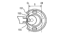
図4では、遊星ギア151が、インターナルギア153の右端側において噛み合い係合する状態を示す。この時、クランクアーム駆動ピン155は、図中最も右側に寄った位置に置かれている。この状態におけるクランクアーム駆動ピン155の中心線がCRで示される。そしてインターナルギア153に対する遊星ギア151の周回動作が図5,6,7,8と進行していく。図8においては、クランクアーム駆動ピン155は、図中最も左側に寄った位置に置かれている。この状態におけるクランクアーム駆動ピン155の中心線がCLで示される。
【0033】
図4と図8の対比から理解されるように、有負荷駆動状態においては、遊星ギア151がインターナルギア153回りに周回動作することにより、当該遊星ギア151に偏心状に設けられたクランクアーム駆動ピン155は、ハンマ101の長軸方向(図中左右方向)に対し、符号Sで示される直線運動量(ストローク量)を有することになる。そして当該直線運動量を利用して、図2に示すクランクアーム159が長軸方向に駆動される。これにより、クランクアーム159の他端側に連接ピン161を介して遊嵌状に取付けられた駆動子163がシリンダ165のボア内で往復直線運動を行う。この結果、ハンマビット113(図1参照)がその長軸方向にハンマ駆動されることとなる。
【0034】
次にハンマビット113に負荷が作用していない駆動態様、すなわち無負荷駆動状態における作用について、図9および図10を参照しつつ説明する。無負荷駆動状態においては、ハンマビット113の被加工材への押圧動作の反力が作用しないことにより、スライドスリーブ付勢スプリング191の図中左方向への付勢力により、スライドスリーブ189は図中左方向に移動される。これにより連接ロッド187を介してスライドスリーブ189に連接されたインターナルギア回転調整手段181は、図中左側に移動する。
【0035】
するとインターナルギア回転調整手段181に設けられた第1係合部183がインターナルギア153の切欠部154aから離脱する。このときインターナルギア153には、変速ギア141(図2参照)の回転力が遊星ギア151を通じて作用しているため、第1係合部183の係合が解除された瞬間に当該インターナルギア153は回転動作する。本実施の形態では、インターナルギア153が90度回転し、図10に示すように他方の切欠部154bにインターナルギア第2係合部185が係合することで、その回転が終了するように設定されている。
【0036】
このとき、遊星ギア151とインターナルギア153との噛み合い係合位置に対するクランクアーム駆動ピン155の相対的な位置関係が変動し、かかる変動状態から、偏心ピン147が周回動作することにより、遊星ギア151は、インターナルギア153に対し、図11から図15に示すように順次に周回動作することとなる。図11では、遊星ギア151が、インターナルギア153の右端側において噛み合い係合する状態を示す。この時、クランクアーム駆動ピン155は、当該遊星ギア151とインターナルギア153の噛み合い係合位置と対向する側の周縁(図中左側の遊星ギア周縁)に位置している。この状態におけるクランクアーム駆動ピン155の中心線がCで示される。
【0037】
そしてインターナルギア153に対する遊星ギア151の周回動作が図12,13,14,15と進行していく。図15では、遊星ギア151が、インターナルギア153の左端側において噛み合い係合する状態を示す。この時、クランクアーム駆動ピン155は、当該遊星ギア151とインターナルギア153の噛み合い係合位置と対向する側の周縁(図中右側の遊星ギア周縁)に位置している。このように遊星ギア151が周回動作するものの、図11から図15までの対比から理解されるように、クランクアーム駆動ピン155の中心線Cは、常にインターナルギア153の中心に不動状に位置している。
【0038】
本実施の形態では、遊星ギア151の外周歯径が当該遊星ギア151の周回径の概ね半分に設定され、遊星ギア151とインターナルギア153の噛み合い係合位置と対向する側に置かれたクランクアーム駆動ピン155は、遊星ギア151の周回動作にも拘わらず、ハンマ101の長軸方向に関してはストロークが見かけ上ゼロになるように設定されている。
【0039】
この結果、無負荷駆動状態においては、遊星ギア151がインターナルギア153回りに周回動作しても、クランクアーム駆動ピン155はハンマ101の長軸方向(図中左右方向)に関しては何ら運動をしないことが帰結される。換言すれば、無負荷駆動状態においては、駆動モータ121が駆動し、遊星ギア151がインターナルギア153回りに周回動作をおこなっているにも拘らず、クランクアーム駆動ピン155は、ハンマ101の長軸方向にクランクアーム159を駆動し得ず、この結果、ハンマビット113にハンマ駆動力は伝達されないこととなる。
【0040】
本実施の形態に係るハンマ101では、無負荷駆動状態から有負荷駆動状態に切替えることで、駆動モータの出力がハンマビット113に伝達される機能、すなわち始動クラッチ機能が付与されることとなる。
【0041】
本実施の形態によれば、ハンマ113に作用する負荷に基づいてインターナルギア153の回転を許容し、遊星ギア151とインターナルギア153の噛み合い係合位置に対するクランクアーム駆動ピン155の位置を相対的に変化させる。これによってクランクアーム159の直線運動量を可変とし、ハンマ101における合理的なハンマビット113の駆動制御を行うことが可能となる。
【0042】
(本発明の第2の実施形態)
本発明の第2の実施形態に係るハンマ201の構成が図16および図17に示される。第2の実施形態に係るハンマ201では、上記した動力伝達機構131における特徴的な要素をクランクアーム159の駆動制御ではなく、当該クランクアーム159によって駆動される打撃子の制振に用いられるカウンタウェイトの駆動制御に用いている。従って、第1の実施形態と同等の部材要素については、便宜上詳細な説明を省略することとする。
【0043】
第2の実施の形態に係るハンマ201は、概括的に見て、駆動モータ221と、当該駆動モータ221の回転出力をハンマビット取付けチャック209に止着されたハンマビット213に伝達する動力伝達機構231と、カウンタウェイト275を駆動するためのカウンタウェイト駆動手段266を有する。
【0044】
ツールホルダ237の図中右側端部と上記動力伝達機構131との間の領域には、インターナルギア回転調整手段281、連接ロッド287、スライドスリーブ289、スライドスリーブ付勢スプリング291、係合部連接スプリング293が配置されている。これらの部材は、カウンタウェイト駆動手段266によるカウンタウェイト275の駆動量を変化するために用いられる要素であり、第1の実施の形態における対応要素と実質的に同等の構成を有する。
【0045】
ハンマ201の動力伝達機構231およびカウンタウェイト駆動手段266を中心とした主要部の詳細な構成が図17に示される。ギアハウジング207内の動力伝達機構231は、駆動モータ221の出力軸223と噛み合い係合する変速ギア241、当該変速ギア241と一体状に回転するギアシャフト243、ギアシャフト243の回転を軸支するギアシャフト支持ベアリング245、ギアシャフト243の回転中心から所定距離偏心した位置において変速ギア241と一体状に形成された偏心ピン247を有する。偏心ピン247は、偏心ピン支持ベアリング248を介してクランクアーム259の一端側に連接される。クランクアーム259の他端側は、連接ピン261を介してシリンダ265のボア内に配置された駆動子263に連接される。
【0046】
さらに偏心ピン247は、偏心ピン受承凹部268に遊嵌状に係合されることで、当該偏心ピン247によって回転可能とされたカウンタウェイト駆動用クランク部267に連接される。カウンタウェイト駆動用クランク部267の回転中心から所定距離だけ偏心した位置には、遊星ギア271が配置される。一方、インターナルギア回転調整手段281を構成する第1係合部283に係合して回転が規制されたインターナルギア269が、カウンタウェイト駆動用クランク部267の内周側に配置されている。インターナルギア269は、カウンタウェイト駆動用クランク部267に接触して、当該カウンタウェイト駆動用クランク部267による回転力の作用を受けるが、上記第1係合部283(ないし第2係合部285)の係合によって回転することが常時には規制されている。カウンタウェイト駆動用クランク部267は、本実施の形態では「キャリア」としての機能を奏する。
【0047】
遊星ギア271の回転中心から所定距離だけ偏心した位置には、カウンタウェイト駆動ピン273が設けられている。このカウンタウェイト駆動ピン273は、本発明における「動力伝達ピン」に対応する。そして当該カウンタウェイト駆動ピン273の上端側はカウンタウェイト275に遊嵌状に連接される。
【0048】
第2の実施の形態に係るハンマ201は上記のように構成される。次に当該ハンマ201の作用および使用方法について説明する。上述の有負荷駆動状態においては、図17に示すように、駆動モータ221の回転出力は出力軸223、変速ギア241、偏心ピン247、クランクアーム259、連接ピン261を介して駆動子263を長軸方向(図中左右方向)に直線運動させる。これによって図16に示すハンマビット213がハンマ駆動される。
【0049】
一方、偏心ピン247がギアシャフト243の回転軸回りに周回動作することで、カウンタウェイト駆動用クランク部267が回転駆動される。このとき、インターナルギア269は、カウンタウェイト駆動用クランク部267の回転力を受けるものの、インターナルギア第1係合部283が係合しているため、回転することが規制された状態にある。
【0050】
このため、カウンタウェイト駆動用クランク部267に偏心状に設けられた遊星ギア271が、インターナルギア269の内周歯周りに周回動作を行なうことになる。これにより、遊星ギア271に偏心状に設けられたカウンタウェイト駆動ピン273が遊星ギア271の中心軸回りに周回動作する。図示を省略するものの、カウンタウェイト275には、その長軸方向と交差する方向に長孔が形成されており、カウンタウェイト275は、その長軸方向に対する駆動ピン273の運動成分のみを受承して直線運動されることになる。これによりカウンタウェイト275は、クランクアーム259によって駆動される打撃子と対向状に往復動し、当該クランクアーム259によって駆動される打撃子の制振を効率的に行なうように構成される。
【0051】
なお、本実施の形態における有負荷駆動状態時の遊星ギア271とインターナルギア269との噛み合い係合位置に対するカウンタウェイト駆動ピン273の相対位置関係については、第1の実施の形態で説明した図4〜図8に示す態様と実質的に同等であり、その説明および図示を省略するものとする。
【0052】
一方、ハンマ201が無負荷駆動状態とされる場合、図16に示すハンマビット213の被加工材への押圧動作の反力が作用しないことにより、スライドスリーブ付勢スプリング291の図中左方向への付勢力により、スライドスリーブ289は図中左方向に移動される。これにより連接ロッド287を介してスライドスリーブ289に連接されたインターナルギア回転調整手段281は、図中左側に移動する。すると図17に示すインターナルギア回転調整手段281に設けられた第1係合部283がインターナルギア269から離脱する。
【0053】
このときインターナルギア269には、カウンタウェイト駆動用クランク部267の回転力が作用しているため、第1係合部283の係合が解除された瞬間に当該インターナルギア269は90度回転し、インターナルギア269の対向側の切欠部に第2係合部285が係合するように設定されている。この結果、遊星ギア271とインターナルギア269との噛み合い係合位置に対するカウンタウェイト駆動ピン273の相対位置関係が変化する。この点については、第1の実施の形態で説明した図11〜図15に示す態様と実質的に同等であり、その説明および図示を省略するものとする。
【0054】
以上より、無負荷駆動状態においては、カウンタウェイト駆動用クランク部267が回転することで、遊星ギア271がインターナルギア269回りに周回動作しても、カウンタウェイト駆動ピン273はハンマ201の長軸方向(図中左右方向)に関する運動成分を有さないことになる。換言すれば、無負荷駆動状態においては、カウンタウェイト275は駆動されない状態が維持されることとなる。これとは逆に、本実施の形態に係るハンマ201では、無負荷駆動状態から有負荷駆動状態に切替えられることで、駆動モータの出力がカウンタウェイト275を駆動する構成とされる。従って、本実施の形態に係るハンマ201では、当該ハンマ201の駆動状態に応じてのカウンタウェイトの駆動制御を自動的に行なうことが可能となり、合理的な制振制御を遂行することが可能となった。
【0055】
【発明の効果】
本発明によれば、電動往復動式工具において、駆動モータの回転出力を工具ビットの長軸方向への直線運動に変換する動力伝達機構の一層の合理化に資する技術が提供されることとなった。
【図面の簡単な説明】
【図1】 本発明の第1の実施の形態に係るハンマの全体構成を示す断面図である。
【図2】 第1の実施の形態に係るハンマの主要部の詳細な構成を示す部分的断面図である。
【図3】 有負荷駆動時における動力伝達機構の構造を示す図である。なお、図示の便宜上、図3のうち、動力伝達機構については平面視、インターナルギア回転調整手段とスライドスリーブを連接する連接ロッドの周辺箇所については底面視として示している。
【図4】 有負荷駆動時における遊星ギアの周回の態様を示す部分的平面図である。
【図5】 同じく、有負荷駆動時における遊星ギアの周回の態様を示す部分的平面図である。
【図6】 同じく、有負荷駆動時における遊星ギアの周回の態様を示す部分的平面図である。
【図7】 同じく、有負荷駆動時における遊星ギアの周回の態様を示す部分的平面図である。
【図8】 同じく、有負荷駆動時における遊星ギアの周回の態様を示す部分的平面図である。
【図9】 第1の実施の形態に係るハンマにつき、無負荷駆動時の状態を示す断面図である。
【図10】 第1の実施の形態に係るハンマにつき、無負荷駆動の際の主要部の詳細な構成を示す。なお、図示の便宜上、図10のうち、動力伝達機構については平面視、インターナルギア回転調整手段とスライドスリーブを連接する連接ロッドの周辺箇所については底面視として示している。
【図11】 無有負荷駆動時における遊星ギアの周回の態様を示す部分的平面図である。
【図12】 同じく、無負荷駆動時における遊星ギアの周回の態様を示す部分的平面図である。
【図13】 同じく、無負荷駆動時における遊星ギアの周回の態様を示す部分的平面図である。
【図14】 同じく、無負荷駆動時における遊星ギアの周回の態様を示す部分的平面図である。
【図15】 同じく、無負荷駆動時における遊星ギアの周回の態様を示す部分的平面図である。
【図16】 本発明の第2の実施の形態に係るハンマの全体構成を示す断面図である。
【図17】 本発明の第2の実施の形態に係るハンマの主要部の詳細な構成を示す部分断面図である。
【符号の説明】
101 ハンマ
103 本体部
105 モータハウジング
107 ギアハウジング
108 クランクキャップ
109 ハンマビット取付けチャック
111 ハンドグリップ
113 ハンマビット(工具ビット)
121 駆動モータ
123 出力軸
125 出力軸ギア部
131 動力伝達機構
133 エアシリンダ機構
135 打撃力伝達機構
137 ツールホルダ
141 変速ギア
143 ギアシャフト
145 ギアシャフト支持ベアリング
147 偏心ピン(動力伝達ピン)
151 遊星ギア
153 インターナルギア
154 切欠部
155 クランクアーム駆動ピン
157 クランクアーム駆動ピン支持ベアリング
159 クランクアーム
161 連接ピン
163 駆動子
165 シリンダ
181 インターナルギア回転調整手段
183 インターナルギア第1係合部(最大ストローク)
185 インターナルギア第2係合部(ストロークゼロ)
187 連接ロッド
189 スライドスリーブ
191 スライドスリーブ付勢スプリング
193 係合部連接スプリング
247 偏心ピン(クランクアーム駆動ピン)
248 偏心ピン支持ベアリング
259 クランクアーム
261 連接ピン
263 駆動子
265 シリンダ
266 カウンタウェイト駆動手段
267 カウンタウェイト駆動用クランク部
268 偏心ピン受承凹部
269 インターナルギア
271 遊星ギア
273 カウンタウェイト駆動ピン(動力伝達ピン)
275 カウンタウェイト[0001]
BACKGROUND OF THE INVENTION
The present invention relates to a construction technique of an electric reciprocating tool having a power transmission mechanism that converts a rotational output of a drive motor into a linear motion of a tool bit in a major axis direction.
[0002]
[Prior art]
Japanese Patent Publication No. 4-31801 (Patent Document 1) discloses a configuration of an electric hammer in which a so-called start clutch is set. In this electric hammer, on / off of the clutch is controlled via a striker and a pusher that are slidable in the axial direction in a spindle that holds the hammer bit. Thereby, even if the drive motor is operated, the hitting means does not reciprocate in a state where the hammer bit is not pressed against the workpiece, and the hitting means of the hitting means is not pressed until the hammer bit is pressed against the workpiece. The operation is configured to be started.
[0003]
According to the above disclosed technique, the driving of the hammer bit is controlled by the cooperation with the start clutch that has improved the start characteristic at the start of the machining operation. However, not only the start characteristic of the drive mechanism is improved, There is a high demand for searching for a more rational mechanism for the operation mode of the drive mechanism in accordance with the acting load.
[0004]
[Patent Document 1]
Japanese Examined Patent Publication No. 4-31801
[0005]
[Problems to be solved by the invention]
The present invention has been made in view of the above points, and contributes to further rationalization of a power transmission mechanism that converts a rotational output of a drive motor into a linear motion in the long axis direction of a tool bit in an electric reciprocating tool. The purpose is to provide technology.
[0006]
[Means for Solving the Problems]
In order to achieve the above object, the invention described in each claim is configured.
According to invention of Claim 1, the electric reciprocating tool which has a tool bit, a drive motor, and a power transmission mechanism is comprised. The electric reciprocating tools widely include work tools such as hammers, hammer drills, jigsaws, reciprocating saws, etc., in which the tool bit performs a work on the workpiece by linear movement. The drive motor drives such a tool bit. The power transmission mechanism is an element that converts the rotational output of the drive motor into linear motion in the tool bit long axis direction, and includes an internal gear, a planetary gear, and a power transmission pin. Of these, the internal gear is configured such that rotation is always restricted. The planetary gear is also configured to engage and engage the internal gear. The power transmission pin is provided eccentrically on the planetary gear. In the power transmission mechanism of the present invention, the planetary gear is revolved around the internal gear in a revolving manner via the drive gear, so that the power transmission pin provided on the planetary gear is revolved around the internal gear together with the planetary gear. Of the rotating operation of the power transmission pin, the power transmission of the drive motor is achieved by utilizing the linear motion component of the tool bit in the long axis direction.
[0007]
In the power transmission mechanism according to the present invention, the power transmission pin is provided eccentrically on the planetary gear, and by allowing a predetermined amount of rotation of the internal gear based on the load acting on the tool bit, the internal gear and the planetary gear are allowed to rotate. It is possible to change the position of the power transmission pin relative to the gear meshing engagement position. “Allowing a predetermined amount of rotation of the internal gear based on the load acting on the tool bit” widely includes a mode of allowing rotation of the internal gear when the load amount acting on the tool bit changes. Load acting in various directions of the tool bit, such as a load acting in the circumferential direction of the tool, and a load acting in the axial direction of the tool bit. For example, it is possible to adopt a mode in which the rotation of the internal gear is allowed when the pressing of the tool against the workpiece by the worker is released during the machining operation. Further, “relatively changing the position of the power transmission pin” broadly encompasses an aspect in which the position of the power transmission pin with respect to the meshing engagement position of the planetary gear with respect to the internal gear is changed.
[0008]
For example, when the meshing engagement between the internal gear and the planetary gear is performed in the front end region or the rear end region in the longitudinal direction of the tool bit, the power transmission pin is disposed in the vicinity of the meshing engagement position. With this configuration, the planetary gear circulates around the internal gear, so that the power transmission pin generates a linear motion component in the longitudinal direction of the tool bit between the front end region and the rear end region. It is possible to operate around while holding. In other words, this configuration makes it possible to ensure a large stroke of the linear motion component of the power transmission pin in the tool bit long axis direction.
[0009]
Further, for example, when the meshing engagement between the internal gear and the planetary gear is performed in the front end region or the rear end region in the longitudinal direction of the tool bit, the power transmission pin is in the meshing engagement position of the planetary gear. If the planetary gear is configured to circulate around the internal gear, the power transmission pin has a length of the tool bit in the region facing the meshing engagement position. It becomes possible to move around while having a linear motion component in the axial direction. With this configuration, the stroke of the linear movement of the power transmission pin in the tool bit major axis direction can be reduced. If the orbiting radius of the planetary gear and the diameter of the planetary gear are set to approximately 2: 1, the power transmission pin disposed on the side facing the meshing engagement position is not affected by the orbiting operation of the planetary gear. The linear motion component in the bit long axis direction is substantially zero, and the stroke of the linear motion component in the tool bit long axis direction of the power transmission pin can be set to zero.
[0010]
Thus, by providing the power transmission pin eccentrically on the planetary gear and allowing the rotation of the internal gear, by utilizing the change in the relative position of the power transmission pin with respect to the meshing engagement position of the internal gear and the planetary gear, The linear momentum of the power transmission pin in the long axis direction of the hammer bit can be changed. In addition, as described above, the mode of “changing the linear momentum” suitably includes a mode in which the linear momentum is zero as well as a mode in which the linear momentum is increased or decreased.
[0011]
According to the present invention, a configuration is adopted in which the position of the power transmission pin is relatively changed based on the load acting on the tool bit to vary the linear momentum in the tool bit long axis direction. For this reason, in various drive mechanisms using the linear momentum of the power transmission pin, such as a tool bit drive mechanism, or a counter weight drive mechanism that controls vibration when driving the tool bit, the tool bit, the counter weight, etc. It becomes possible to appropriately change the driving amount of the driving object. In particular, the drive amount of the object to be driven can be made variable based on the load acting on the tool bit. It becomes possible to change the driving amount of the driven object in accordance with the work state such as driving, and rational driving control in the electric reciprocating tool can be performed.
[0012]
As described above, the mechanism that makes the drive amount of the driven object variable based on the load acting on the tool bit can be applied to various working modes of the electric reciprocating tool. For example, if the tool bit drive amount is set to zero when the load on the tool bit is released, the tool bit can be used as a starting clutch in an electric hammer or the like. Moreover, in this case, since the drive control of the tool bit can be performed only by changing the relative position of the power transmission pins without increasing or decreasing the rotational output of the drive motor, the starting characteristics of the tool can be improved. It becomes possible.
In the present invention, as a specific mechanism for changing the drive amount of the object to be driven, the tool bit moves based on the movement operation in the long axis direction of the tool bit by the pressing operation on the workpiece and the pressing release operation. Therefore, by restricting the rotation of the internal gear or allowing a predetermined amount of rotation, and thereby changing the position of the power transmission pin relative to the meshing engagement position of the internal gear and the planetary gear, There is an internal gear rotation adjusting means for changing the linear momentum in the tool bit long axis direction.
The internal gear rotation adjusting means has a first engagement portion and a second engagement portion. The first engaging portion engages with an internal gear and fixes the internal gear at a predetermined rotation position when the tool bit is pressed against the workpiece and is loaded, and the tool bit is fixed to the workpiece. At the time of no-load driving in which the pressure is released, the engagement with the internal gear is released and the rotation of the internal gear is allowed, and the second engagement portion is the first gear for the internal gear at the time of no-load driving. The internal gear is fixed by engaging with the internal gear at a position rotated from the engaging position of the engaging portion by a predetermined angle, for example, approximately 90 degrees, and when the load is driven, the internal gear is disengaged to release the internal gear. Configured to allow rotation of the lugear. By adopting such a configuration, the stroke of the linear motion component of the power transmission pin in the tool bit long axis direction is ensured during load loading, and the tool bit long axis direction of the power transmission pin in no load driving. It is possible to reduce the stroke of the linear motion component.
[0013]
(Invention of Claim 2)
According to the second aspect of the present invention, the electric reciprocating tool according to the first aspect has a configuration in which the linear motion of the power transmission pin in the tool bit long axis direction is used for the drive mechanism of the tool bit. It is done. That is, in the electric reciprocating tool according to claim 2, the tool bit is configured as a hammer bit that receives hammering force from the hammer and performs a hammering operation on the workpiece, and the power transmission pin includes the hammer bit. Is configured to be connected to a crank arm for linearly driving the hammer bit in the longitudinal direction. With this configuration, the position of the power transmission pin is relatively changed based on the load acting on the hammer bit, and accordingly, the linear momentum of the power transmission pin in the long axis direction of the hammer bit is appropriately changed. Convenience can be achieved.
[0014]
(Invention of Claim 3)
According to the third aspect of the present invention, in the electric reciprocating tool according to the first aspect, the linear motion of the power transmission pin in the tool bit long axis direction is controlled when the tool bit is driven. The structure used for the counterweight drive mechanism is obtained. That is, in the electric reciprocating tool according to claim 3, the tool bit is configured as a hammer bit that receives hammering force by the hammer and performs a hammering operation on the workpiece, and the power transmission pin is a straight line of the hammer. It is configured to be used for driving a counterweight that linearly moves opposite to the movement. With this configuration, the position of the power transmission pin can be relatively changed based on the load acting on the hammer bit. As a result, the linear momentum of the power transmission pin in the long axis direction of the hammer bit is appropriately changed, and the driving amount of the counterweight at the time of hammering is appropriately changed. It is possible to change accordingly.
[0015]
In particular, in the present invention, the driving amount of the counter weight can be changed based on the load acting on the hammer bit. For example, the driving mode in which the load acts on the hammer bit, that is, the loaded driving state and the load on the hammer bit. It is possible to automatically adjust the damping amount by the counterweight or the presence / absence of damping between the driving mode in which no operation occurs, that is, the no-load driving state.
[0016]
In view of the gist of the invention, the following aspects can be configured.
(Aspect 1)
“Electric reciprocating tool according to claim 1,
By allowing the internal gear to rotate based on the load acting on the tool bit, the meshing engagement of the internal gear and the planetary gear causes the front end region or the rear end of the tool bit in the longitudinal direction. An electric reciprocating tool characterized in that the power transmission pin is arranged at the meshing engagement position or in the vicinity thereof when being used in a region. "
[0017]
With this configuration, the planetary gear revolves around the internal gear, so that the power transmission pin linearly moves in the long axis direction of the tool bit between the front end region and the rear end region. Thus, it is possible to ensure a large stroke of the linear motion of the power transmission pin in the tool bit long axis direction.
[0018]
(Aspect 2)
"Electric reciprocating tool according to claim 1 or aspect 2,
By allowing the internal gear to rotate based on the load acting on the tool bit, the meshing engagement of the internal gear and the planetary gear causes the front end region or the rear end of the tool bit in the longitudinal direction. An electric reciprocating tool characterized in that the power transmission pin is arranged in a peripheral region of the planetary gear on the side facing the meshing engagement position when it is made in the region. "
[0019]
With this configuration, the planetary gear rotates around the internal gear, so that the power transmission pin can linearly move in the longitudinal direction of the tool bit in the region facing the meshing engagement position. Become. With this configuration, the stroke of the linear movement of the power transmission pin in the tool bit major axis direction can be reduced.
[0020]
(Aspect 3)
“Electric reciprocating tool according to aspect 2,
An electric reciprocating tool characterized in that the orbiting diameter of the planetary gear and the diameter of the planetary gear are set to approximately 2: 1. "
[0021]
If comprised in this way, the power transmission pin arrange | positioned on the side facing the meshing engagement position of an internal gear and a planetary gear will be a linear motion component to a tool bit long-axis direction irrespective of the rotation operation | movement of a planetary gear. It becomes easy to set so as not to have a stroke, and the stroke can be made zero.
[0022]
DETAILED DESCRIPTION OF THE INVENTION
(First embodiment)
Hereinafter, a hammer according to a first embodiment of the present invention will be described in detail with reference to the drawings. The overall configuration of the
[0023]
A
[0024]
The
[0025]
FIG. 2 shows a detailed configuration of the main part centering on the
[0026]
Further, the
[0027]
In the present embodiment, the diameter of the
[0028]
The
[0029]
The
[0030]
In the loaded drive state, the
[0031]
In this state, the crank
[0032]
FIG. 4 shows a state where the
[0033]
As understood from the comparison between FIG. 4 and FIG. 8, in the loaded drive state, the
[0034]
Next, the driving mode in which no load is applied to the
[0035]
Then, the first engaging
[0036]
At this time, the relative positional relationship of the crank
[0037]
Then, the orbiting operation of the
[0038]
In the present embodiment, the outer peripheral tooth diameter of the
[0039]
As a result, in the no-load drive state, even if the
[0040]
In the
[0041]
According to the present embodiment, the
[0042]
(Second embodiment of the present invention)
The configuration of a
[0043]
The
[0044]
In an area between the right end portion of the
[0045]
FIG. 17 shows a detailed configuration of the main part centering on the
[0046]
Further, the
[0047]
A
[0048]
The
[0049]
On the other hand, when the
[0050]
For this reason, the
[0051]
Note that the relative positional relationship of the
[0052]
On the other hand, when the
[0053]
At this time, since the rotational force of the counterweight drive crank
[0054]
As described above, in the no-load driving state, the
[0055]
【The invention's effect】
According to the present invention, in the electric reciprocating tool, there is provided a technology that contributes to further rationalization of the power transmission mechanism that converts the rotational output of the drive motor into a linear motion in the long axis direction of the tool bit. .
[Brief description of the drawings]
FIG. 1 is a cross-sectional view showing an overall configuration of a hammer according to a first embodiment of the present invention.
FIG. 2 is a partial cross-sectional view showing a detailed configuration of a main part of the hammer according to the first embodiment.
FIG. 3 is a diagram showing a structure of a power transmission mechanism at the time of driving with load. For convenience of illustration, in FIG. 3, the power transmission mechanism is shown in plan view, and the peripheral portions of the connecting rod connecting the internal gear rotation adjusting means and the slide sleeve are shown in bottom view.
FIG. 4 is a partial plan view showing an orbiting mode of the planetary gear when driving with load.
FIG. 5 is also a partial plan view showing an aspect of rotation of the planetary gear during load driving.
FIG. 6 is also a partial plan view showing how the planetary gear circulates during load driving.
FIG. 7 is also a partial plan view showing an aspect of rotation of the planetary gear during load driving.
FIG. 8 is also a partial plan view showing an aspect of rotation of the planetary gear during load driving.
FIG. 9 is a cross-sectional view showing a state during no-load driving of the hammer according to the first embodiment.
FIG. 10 shows a detailed configuration of a main part of the hammer according to the first embodiment at the time of no-load driving. For convenience of illustration, in FIG. 10, the power transmission mechanism is shown in plan view, and the peripheral portions of the connecting rod connecting the internal gear rotation adjusting means and the slide sleeve are shown in bottom view.
FIG. 11 is a partial plan view showing an aspect of rotation of the planetary gear when driving without load.
FIG. 12 is also a partial plan view showing how the planetary gear circulates during no-load driving.
FIG. 13 is also a partial plan view showing how the planetary gear circulates during no-load driving.
FIG. 14 is also a partial plan view showing an aspect of rotation of the planetary gear during no-load driving.
FIG. 15 is also a partial plan view showing an aspect of rotation of the planetary gear during no-load driving.
FIG. 16 is a cross-sectional view showing an overall configuration of a hammer according to a second embodiment of the present invention.
FIG. 17 is a partial cross-sectional view showing a detailed configuration of a main part of a hammer according to a second embodiment of the present invention.
[Explanation of symbols]
101 Hammer
103 Main body
105 Motor housing
107 gear housing
108 Crank cap
109 Hammer Bit Mounting Chuck
111 hand grip
113 Hammer Bit (Tool Bit)
121 Drive motor
123 Output shaft
125 Output shaft gear
131 Power transmission mechanism
133 Air cylinder mechanism
135 Impact force transmission mechanism
137 Tool holder
141 transmission gear
143 Gear shaft
145 Gear shaft support bearing
147 Eccentric pin (Power transmission pin)
151 planetary gear
153 Internal gear
154 Notch
155 Crank arm drive pin
157 Crank arm drive pin support bearing
159 Crank arm
161 Connecting pin
163 Driver
165 cylinder
181 Internal gear rotation adjustment means
183 Internal gear first engagement part (maximum stroke)
185 Internal gear second engagement part (zero stroke)
187 Connecting rod
189 slide sleeve
191 Slide sleeve bias spring
193 Engagement connecting spring
247 Eccentric pin (Crank arm drive pin)
248 Eccentric pin support bearing
259 Crank arm
261 Connecting pin
263 Driver
265 cylinder
266 Counterweight drive means
267 Crank for driving counterweight
268 Eccentric pin receiving recess
269 Internal gear
271 Planetary Gear
273 Counterweight drive pin (power transmission pin)
275 counter weight
Claims (3)
前記工具ビットを駆動するための駆動モータと、
前記駆動モータの回転出力を前記工具ビット長軸方向への直線運動に変換する動力伝達機構と、
前記動力伝達機構における前記工具ビット長軸方向への直線運動量を変えるインターナルギア回転調整手段を有する電動往復動式工具であって、
前記動力伝達機構は、
インターナルギアと、
前記インターナルギアに噛み合い係合する遊星ギアと、
前記遊星ギアに偏心状に設けられた動力伝達ピンを有し、
前記インターナルギア回転調整手段は、前記工具ビットの被加工材に対する押圧動作及び押圧解除動作による当該工具ビットの長軸方向の移動動作に基づいて移動することで、前記インターナルギアの回転を規制し、または所定量の回転を許容し、これによって前記インターナルギアと前記遊星ギアの噛み合い係合位置に対する前記動力伝達ピンの位置を相対的に変化させることで、前記動力伝達ピンの前記工具ビット長軸方向への直線運動量を変化させるものであり、前記工具ビットが被加工材に押圧された有負荷駆動時には、前記インターナルギアと係合して当該インターナルギアを予め定めた回動位置に固定し、前記工具ビットの被加工材に対する押圧が解除された無負荷駆動時には、前記インターナルギアとの係合を解除して当該インターナルギアの回転を許容する第1係合部と、前記無負荷駆動時には、前記インターナルギアに対する前記第1係合部の係合位置から所定角度回転された位置でインターナルギアと係合して当該インターナルギアを固定し、前記有負荷駆動時には、前記インターナルギアとの係合を解除して前記インターナルギアの回転を許容する第2係合部を有することを特徴とする電動往復動式工具。A tool bit that performs machining on the workpiece by linear motion;
A drive motor for driving the tool bit;
A power transmission mechanism for converting the rotational output of the drive motor into linear motion in the tool bit long axis direction;
An electric reciprocating tool having an internal gear rotation adjusting means for changing a linear momentum in the tool bit major axis direction in the power transmission mechanism ,
The power transmission mechanism is
And stomach Ntanarugia,
A planetary gear meshingly engaged with the internal gear;
A power transmission pin provided eccentrically on the planetary gear;
The internal gear rotation adjusting means regulates the rotation of the internal gear by moving based on the movement operation of the tool bit in the major axis direction by the pressing operation and the pressing release operation of the tool bit against the workpiece, or allowing the rotation of the predetermined amount, whereby by relatively changing the position of the power transmission pin for interlocking engagement position of the planetary gear and the internal gear, the axial direction of the tool bit of the power transmission pin And when the load is driven when the tool bit is pressed against the workpiece, the internal gear engages with the internal gear and fixes the internal gear at a predetermined rotational position, At the time of no-load driving in which the tool bit is released from being pressed, the engagement with the internal gear is released and the A first engagement portion that allows rotation of the internal gear, and at the time of no-load driving, the internal gear engages with the internal gear at a position rotated by a predetermined angle from the engagement position of the first engagement portion with respect to the internal gear. An electric reciprocating tool having a second engagement portion that fixes a gear and releases the engagement with the internal gear and allows the internal gear to rotate during the load driving .
前記工具ビットは、打撃子による打撃力を受承して被加工材にハンマ作業を行うハンマビットとして構成され、
前記動力伝達ピンは、前記打撃子を前記ハンマビット長軸方向へ直線状に駆動させるためのクランクアームに接続されていることを特徴とする電動往復動式工具。The electric reciprocating tool according to claim 1,
The tool bit is configured as a hammer bit that receives a striking force by a striker and performs a hammering operation on a workpiece.
The power transmission pin is connected to a crank arm for driving the striker linearly in the long axis direction of the hammer bit.
前記工具ビットは、打撃子による打撃力を受承して被加工材にハンマ作業を行うハンマビットとして構成され、
前記動力伝達ピンは、前記打撃子の直線運動と対向状に直線運動するカウンタウェイトの駆動に用いられることを特徴とする電動往復動式工具。The electric reciprocating tool according to claim 1,
The tool bit is configured as a hammer bit that receives a striking force by a striker and performs a hammering operation on a workpiece.
The power transmission pin is used for driving a counterweight that linearly moves in a direction opposite to the linear motion of the striker.
Priority Applications (4)
| Application Number | Priority Date | Filing Date | Title |
|---|---|---|---|
| JP2003005144A JP4270887B2 (en) | 2003-01-10 | 2003-01-10 | Electric reciprocating tool |
| DE60336112T DE60336112D1 (en) | 2003-01-10 | 2003-12-30 | Floating power tool |
| EP03030011A EP1437200B1 (en) | 2003-01-10 | 2003-12-30 | Reciprocating power tool |
| US10/754,737 US7059425B2 (en) | 2003-01-10 | 2004-01-09 | Reciprocating power tool |
Applications Claiming Priority (1)
| Application Number | Priority Date | Filing Date | Title |
|---|---|---|---|
| JP2003005144A JP4270887B2 (en) | 2003-01-10 | 2003-01-10 | Electric reciprocating tool |
Publications (2)
| Publication Number | Publication Date |
|---|---|
| JP2004216484A JP2004216484A (en) | 2004-08-05 |
| JP4270887B2 true JP4270887B2 (en) | 2009-06-03 |
Family
ID=32501262
Family Applications (1)
| Application Number | Title | Priority Date | Filing Date |
|---|---|---|---|
| JP2003005144A Expired - Fee Related JP4270887B2 (en) | 2003-01-10 | 2003-01-10 | Electric reciprocating tool |
Country Status (4)
| Country | Link |
|---|---|
| US (1) | US7059425B2 (en) |
| EP (1) | EP1437200B1 (en) |
| JP (1) | JP4270887B2 (en) |
| DE (1) | DE60336112D1 (en) |
Families Citing this family (33)
| Publication number | Priority date | Publication date | Assignee | Title |
|---|---|---|---|---|
| JP4195818B2 (en) * | 2003-01-16 | 2008-12-17 | 株式会社マキタ | Electric hammer |
| DE10328061A1 (en) * | 2003-06-23 | 2005-01-20 | Robert Bosch Gmbh | Motor-driven jigsaw |
| DE602005006342T2 (en) * | 2004-03-18 | 2009-06-10 | Positec Power Tools (Suzhou) Co., Ltd. | Powered tool |
| DE102004019865A1 (en) * | 2004-04-23 | 2005-11-17 | Wacker Construction Equipment Ag | Device for converting rotational movement into translation movement has hollow wheel with inner wheel and crank with follower on inner wheel converting movement without transverse motion |
| EP1779979B1 (en) * | 2004-04-30 | 2018-02-21 | Makita Corporation | Working tool |
| JP4527468B2 (en) | 2004-08-17 | 2010-08-18 | 株式会社マキタ | Electric tool |
| ATE396838T1 (en) * | 2004-12-23 | 2008-06-15 | Black & Decker Inc | POWER TOOL HOUSING |
| EP1690640B1 (en) * | 2005-02-10 | 2013-03-06 | Black & Decker Inc. | Hand-held hammer machine |
| US8261851B2 (en) | 2005-04-11 | 2012-09-11 | Makita Corporation | Electric hammer |
| WO2006109772A1 (en) | 2005-04-11 | 2006-10-19 | Makita Corporation | Electric hammer |
| JP5041575B2 (en) * | 2006-03-07 | 2012-10-03 | 日立工機株式会社 | Impact tool |
| JP4812471B2 (en) * | 2006-03-09 | 2011-11-09 | 株式会社マキタ | Work tools |
| WO2007119334A1 (en) * | 2006-03-13 | 2007-10-25 | Honda Motor Co., Ltd. | Tool head, machine tool and boring method of bore of cylinder block using the machine tool |
| DE102006052253B3 (en) * | 2006-11-03 | 2008-07-10 | Zf Friedrichshafen Ag | Adjustment drive for local adjustment of a chassis component |
| US7832498B2 (en) | 2007-06-15 | 2010-11-16 | Makita Corporation | Impact tool |
| JP5202997B2 (en) * | 2008-03-05 | 2013-06-05 | 株式会社マキタ | Work tools |
| US8196674B2 (en) * | 2008-03-05 | 2012-06-12 | Makita Corporation | Impact tool |
| DE102009029055A1 (en) * | 2009-09-01 | 2011-03-10 | Robert Bosch Gmbh | Drilling and / or chiselling device |
| JP2010214587A (en) * | 2010-07-07 | 2010-09-30 | Makita Corp | Working tool |
| DE102010062099A1 (en) * | 2010-11-29 | 2012-05-31 | Robert Bosch Gmbh | Hammer mechanism |
| CN202021588U (en) * | 2011-03-29 | 2011-11-02 | 南京德朔实业有限公司 | Electric hammer |
| JP5767511B2 (en) * | 2011-06-01 | 2015-08-19 | 株式会社マキタ | Reciprocating work tool |
| US9630307B2 (en) | 2012-08-22 | 2017-04-25 | Milwaukee Electric Tool Corporation | Rotary hammer |
| US10052747B2 (en) * | 2012-09-03 | 2018-08-21 | Makita Corporation | Hammer tool |
| CN104837427B (en) | 2012-11-14 | 2017-09-22 | 不列颠哥伦比亚癌症机构分部 | Tubulose hammer drill accessory |
| CN104512437B (en) * | 2013-09-30 | 2017-01-11 | 西门子信号有限公司 | Point switch machine |
| WO2015043541A1 (en) * | 2013-09-30 | 2015-04-02 | 西门子信号有限公司 | Point machine |
| CN105722647A (en) * | 2013-11-26 | 2016-06-29 | 日立工机株式会社 | Electrical power tool |
| JP6987599B2 (en) * | 2017-10-20 | 2022-01-05 | 株式会社マキタ | Strike tool |
| CN213259295U (en) | 2017-10-20 | 2021-05-25 | 米沃奇电动工具公司 | Impact tool for performing cutting operations on a workpiece by means of a chisel |
| EP3743245B1 (en) | 2018-01-26 | 2024-04-10 | Milwaukee Electric Tool Corporation | Percussion tool |
| EP3888851A1 (en) * | 2020-04-03 | 2021-10-06 | Hilti Aktiengesellschaft | Electric handheld machine tool |
| CN112393890B (en) * | 2020-11-20 | 2023-05-05 | 中航飞机起落架有限责任公司 | Pulling load loading device and method for fatigue test |
Family Cites Families (21)
| Publication number | Priority date | Publication date | Assignee | Title |
|---|---|---|---|---|
| US634194A (en) * | 1898-11-22 | 1899-10-03 | William C Woodward | Gearing for pumping-jacks. |
| US3650336A (en) * | 1970-05-05 | 1972-03-21 | Rockwell Mfg Co | Power driven device |
| JPS516583U (en) * | 1974-07-02 | 1976-01-17 | ||
| JPS516583A (en) | 1974-07-05 | 1976-01-20 | Diesel Kiki Co | KAITENKENSHUTSUSOCHI |
| DE2832169A1 (en) * | 1978-07-21 | 1980-01-31 | Hilti Ag | MOTORIZED DRILLING HAMMER |
| DE3116851A1 (en) * | 1981-04-28 | 1982-11-11 | Hilti AG, 9494 Schaan | DRILL AND CHISEL HAMMER |
| DE3505544A1 (en) * | 1985-02-18 | 1986-08-21 | Hilti Ag, Schaan | Hammer drill |
| JPH0431801A (en) | 1990-05-28 | 1992-02-04 | Yoshiyuki Aomi | Variable optical attenuator |
| DE4038586A1 (en) * | 1990-12-04 | 1992-06-11 | Bosch Gmbh Robert | HAND MACHINE TOOL WITH Eccentric Gear |
| DE4207295A1 (en) * | 1992-03-07 | 1993-09-09 | Black & Decker Inc | DRILLING HAMMER |
| DE19510964A1 (en) * | 1995-03-24 | 1996-09-26 | Hilti Ag | Hand tool for dry machining of brittle and / or ductile components and adapter for a hammer drill |
| JP3292969B2 (en) * | 1995-08-18 | 2002-06-17 | 株式会社マキタ | Hammer drill |
| DE19534850A1 (en) * | 1995-09-20 | 1997-03-27 | Hilti Ag | Impact-supported hand drill |
| DE19646382A1 (en) * | 1996-11-11 | 1998-05-14 | Hilti Ag | Handheld device |
| GB9718312D0 (en) * | 1997-08-30 | 1997-11-05 | Black & Decker Inc | Power tool |
| DE10019071A1 (en) * | 2000-04-18 | 2001-10-25 | Hilti Ag | Electric hand tool device with blank stop |
| DE10033362A1 (en) * | 2000-07-08 | 2002-01-17 | Hilti Ag | Electric hand tool with empty stroke shutdown |
| DE10034359A1 (en) * | 2000-07-14 | 2002-01-24 | Hilti Ag | Hitting electric hand tool device |
| JP4281273B2 (en) * | 2000-10-20 | 2009-06-17 | 日立工機株式会社 | Hammer drill |
| JP2002239835A (en) * | 2001-02-16 | 2002-08-28 | Makita Corp | Reciprocating type tool |
| GB0121947D0 (en) * | 2001-09-12 | 2001-10-31 | Black & Decker Inc | Tool holder for hammer |
-
2003
- 2003-01-10 JP JP2003005144A patent/JP4270887B2/en not_active Expired - Fee Related
- 2003-12-30 DE DE60336112T patent/DE60336112D1/en not_active Expired - Lifetime
- 2003-12-30 EP EP03030011A patent/EP1437200B1/en not_active Expired - Fee Related
-
2004
- 2004-01-09 US US10/754,737 patent/US7059425B2/en not_active Expired - Fee Related
Also Published As
| Publication number | Publication date |
|---|---|
| JP2004216484A (en) | 2004-08-05 |
| US7059425B2 (en) | 2006-06-13 |
| EP1437200A1 (en) | 2004-07-14 |
| US20040194986A1 (en) | 2004-10-07 |
| DE60336112D1 (en) | 2011-04-07 |
| EP1437200B1 (en) | 2011-02-23 |
Similar Documents
| Publication | Publication Date | Title |
|---|---|---|
| JP4270887B2 (en) | Electric reciprocating tool | |
| JP4527468B2 (en) | Electric tool | |
| JP5345893B2 (en) | Impact tool | |
| CN109421026A (en) | Power tool | |
| WO2005105386A1 (en) | Working tool | |
| US10500706B2 (en) | Power tool | |
| JP2010005751A (en) | Hand-held working tool | |
| JP6510250B2 (en) | Work tools | |
| JP4456559B2 (en) | Work tools | |
| JP2017042887A (en) | Hammering tool | |
| JP6517634B2 (en) | Impact tool | |
| JP5356097B2 (en) | Impact tool | |
| JP4568600B2 (en) | Hammer drill | |
| JP4243093B2 (en) | Electric hammer | |
| JPH06210507A (en) | Motive power changeover mechanism in rotary tool | |
| JP2000291762A (en) | Reciprocating mechanism and electric tool using the same | |
| CN112757231B (en) | Hammer drill | |
| JP7465647B2 (en) | Hammer Drill | |
| JP6348337B2 (en) | Reciprocating work tool | |
| US11969867B2 (en) | Hand-held power tool | |
| JPH11333742A (en) | Impact tool | |
| JP6517633B2 (en) | Impact tool | |
| JP2024007799A (en) | hammer drill | |
| WO2024020476A1 (en) | Outer ring drive planetary gear assembly | |
| JP4485462B2 (en) | Work tools |
Legal Events
| Date | Code | Title | Description |
|---|---|---|---|
| A621 | Written request for application examination |
Free format text: JAPANESE INTERMEDIATE CODE: A621 Effective date: 20050715 |
|
| A977 | Report on retrieval |
Free format text: JAPANESE INTERMEDIATE CODE: A971007 Effective date: 20070905 |
|
| A131 | Notification of reasons for refusal |
Free format text: JAPANESE INTERMEDIATE CODE: A131 Effective date: 20080110 |
|
| A521 | Written amendment |
Free format text: JAPANESE INTERMEDIATE CODE: A523 Effective date: 20080307 |
|
| TRDD | Decision of grant or rejection written | ||
| A01 | Written decision to grant a patent or to grant a registration (utility model) |
Free format text: JAPANESE INTERMEDIATE CODE: A01 Effective date: 20090203 |
|
| A01 | Written decision to grant a patent or to grant a registration (utility model) |
Free format text: JAPANESE INTERMEDIATE CODE: A01 |
|
| A61 | First payment of annual fees (during grant procedure) |
Free format text: JAPANESE INTERMEDIATE CODE: A61 Effective date: 20090224 |
|
| FPAY | Renewal fee payment (event date is renewal date of database) |
Free format text: PAYMENT UNTIL: 20120306 Year of fee payment: 3 |
|
| R150 | Certificate of patent or registration of utility model |
Free format text: JAPANESE INTERMEDIATE CODE: R150 |
|
| FPAY | Renewal fee payment (event date is renewal date of database) |
Free format text: PAYMENT UNTIL: 20120306 Year of fee payment: 3 |
|
| FPAY | Renewal fee payment (event date is renewal date of database) |
Free format text: PAYMENT UNTIL: 20120306 Year of fee payment: 3 |
|
| FPAY | Renewal fee payment (event date is renewal date of database) |
Free format text: PAYMENT UNTIL: 20120306 Year of fee payment: 3 |
|
| FPAY | Renewal fee payment (event date is renewal date of database) |
Free format text: PAYMENT UNTIL: 20130306 Year of fee payment: 4 |
|
| FPAY | Renewal fee payment (event date is renewal date of database) |
Free format text: PAYMENT UNTIL: 20130306 Year of fee payment: 4 |
|
| FPAY | Renewal fee payment (event date is renewal date of database) |
Free format text: PAYMENT UNTIL: 20140306 Year of fee payment: 5 |
|
| R250 | Receipt of annual fees |
Free format text: JAPANESE INTERMEDIATE CODE: R250 |
|
| LAPS | Cancellation because of no payment of annual fees |