JP4268312B2 - Optical recording / reproducing device - Google Patents
Optical recording / reproducing device Download PDFInfo
- Publication number
- JP4268312B2 JP4268312B2 JP2000121858A JP2000121858A JP4268312B2 JP 4268312 B2 JP4268312 B2 JP 4268312B2 JP 2000121858 A JP2000121858 A JP 2000121858A JP 2000121858 A JP2000121858 A JP 2000121858A JP 4268312 B2 JP4268312 B2 JP 4268312B2
- Authority
- JP
- Japan
- Prior art keywords
- recording
- mark
- pulse
- reproducing apparatus
- power
- Prior art date
- Legal status (The legal status is an assumption and is not a legal conclusion. Google has not performed a legal analysis and makes no representation as to the accuracy of the status listed.)
- Expired - Fee Related
Links
Images


Landscapes
- Optical Recording Or Reproduction (AREA)
- Optical Head (AREA)
Description
【0001】
【発明の属する技術分野】
本発明は、光ディスク等の光学的記録媒体にレーザ光を照射することによって、マークエッジ記録方式に従った情報の記録を実行し、また記録媒体から情報を再生することができる光学的記録再生装置に関する。特に、本発明は、記録媒体の記録感度が低い場合でも、形成するマークの中央が細くならないようにすることが可能な光学的記録再生装置に関する。
【0002】
【従来の技術】
情報を光学的に書き換えることが可能な記録媒体としては、相変化型記録媒体や光磁気記録媒体が知られている。
【0003】
相変化型記録媒体に情報を書き込む場合、絞られたレーザ光を記録媒体の記録膜に照射し、記録膜を加熱融解させる。レーザ光の強度のレベルに応じて記録膜の到達温度及び冷却過程が異なるため、レーザー光の強度を変調することによって記録膜の光学特性(屈折率など)を局所的に変化させることが可能である。より具体的には、レーザー光の強度が所定のレベルを超えて強い場合、記録膜の照射部分は高温状態から急速に冷却するのでアモルファス化する。一方、レーザー光が比較的弱い場合、記録膜の照射部分は中高温状態から徐々に冷却するので結晶化する。記録膜においてアモルファス化した部分は「マーク」と呼ばれ、結晶化した部分は「スペース」と呼ばれる。マークとスペースとでは、屈折率などの光学特性が異なっている。マークおよびスペースの配列によって二値情報を記憶することが可能である。
【0004】
相変化型記録媒体から記録情報を再生する場合、記録膜が相変化を起こさない程度に弱いレーザー光(再生光)を記録膜に照射し、その反射光を検出する。アモルファス化したマーク部分は相対的に反射率が低く、結晶化したスペース部分は相対的に反射率が高い。よって、マークからの反射光とスペースからの反射光とについて光量の違いを検出すれば、再生信号を得ることができる。
【0005】
情報記録方式としてはパルス位置変調方式(PPM:Pulse Position Modulation)とパルス幅変調方式(PWM:Pulse Width Modulation)がある。パルス幅変調方式による記録はマークエッジ記録とも呼ばれる。
【0006】
PPM記録では、パルス幅が一定の比較的短いマークを様々な長さのスペースをあけて記録し、マークの位置に記録情報を割り当てる。一方、PWM記録では、様々な長さのマークを様々な長さのスペースをあけて記録し、マーク長およびスペース長の両方に記録情報を割り当てる。通常、PPMよりもPWMを採用する方が情報記録密度を高くすることができる。
【0007】
PWM記録を行う場合、PPM記録と比較して長いマークを記録する。相変化型記録媒体に長いマークを記録すると、記録膜の蓄熱/放熱効果や記録感度の多様性のために、マークの幅(トラック方向に垂直なサイズ)が不均一になることがある。また、1つの長いマークを形成するために連続した記録光を記録膜に照射し続けると、長いマークの後半部に熱が過剰に蓄積し、マーク幅が広がることが知られている。このため、1つのマークを形成する場合でも、記録光を更に短い複数のパルスから構成する方式(ライト・ストラテジ)が採用されている。このように複数のパルスを用いて各マークを形成する方法および記録再生装置は、例えば、米国特許5,490,126号や米国特許5,636,194号に開示されている。
【0008】
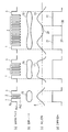
図2(a)〜(d)は、それぞれ、記録光の波形、記録膜に形成されたマークの形状、再生信号の波形、再生信号から形成された2値化信号を示している。なお、記録光の波形は、記録光の変調に用いられる電気信号の波形によって規定される。この電気信号を記録パルスと称する。記録光のパワーは、記録パルスの振幅に比例する。記録光の光源(例えば半導体レーザ)の性質によっては、記録光の波形と記録パルスの波形との間に、本質的でない差異が生じる場合があるが、本明細書では、記録光の波形と記録パルスの波形とを厳密には区別しないこととする。
【0009】
まず、図2(a)を参照する。1つのマークを形成するために用いられる記録光は、時間軸方向に並んだ前端パルス1、くし型パルス列2、および後端パルス3から構成されている。この記録光のパワーは、ピークパワー(Pp)、バイアスパワー1(Pb1)、およびバイアスパワー2(Pb2)の間で変調される。
【0010】
記録光を記録媒体に照射し、記録膜に各マークを形成しつつある期間(以下、「マーク区間」と称する)においては、記録光のパワーはピークパワー(Pp)とバイアスパワー2(Pb2)の間で変調される。一方、記録膜に各スペースを形成しつつある期間(以下、「スペース区間」と称する)では、記録光のパワーはバイアスパワー1(Pb1)に維持される。
【0011】
一般に、光学的記録再生装置は、種々の記録特性をもった光記録媒体に対して情報の記録再生を適切に実行する必要がある。記録光のパワーの平均値(マーク区間における平均値)を一定レベルに固定して情報の記録を行うと、記録感度の相対的に低い記録媒体に形成したマークの長さや幅が小さくなる傾向がある。このため、従来の光学的記録再生装置では、記録媒体の記録感度に応じて適切な光パワーを初期設定した後、マークの長さや幅を適切な大きさにするため、記録光パワーの補償動作が実行されている(記録光パワーの学習)。このような光学的記録再生装置では、比較的短いマークをテスト的に記録し、その短いマークを正確に記録できるように記録光パワーの補償が行われている。これは、再生振幅強度の小さな短いマークを適切に記録することが最重要課題だったからである。
【0012】
【発明が解決しようとする課題】
しかしながら、従来の記録光パワー補償を行ったとしても、どうしても読み取りエラーが生じてしまうことを本発明者は見出した。本発明者は、このような読み取りエラーの発生原因が比較的長いマークに起因して生じることを見出し、本発明を想到するに至った。
【0013】
以下、従来技術に関する本発明者の分析結果を説明する。
【0014】
まず、図2(b)を参照する。図2(b)に示されるマーク4は、くし型パルス列2の熱エネルギー(=「記録光のマーク区間における平均パワー」)が不足した場合に形成されるマークの一例である。このマーク4の幅は、マークの前端部および後端部で相対的に広く、前端部と後端部との間の中間領域で細くなっている。このようなマーク形状を「中細り」と称することとする。
【0015】
このようなマーク4に再生光を照射し、その反射光を光検出器で受光して電気信号に変換すると、図2(c)の左部分に示されるような双峰型波形を持った再生信号5が得られる。しきい値6を基準にして再生信号5を2値化すると、図2(d)の左部分に示されるように、2つの分割パルス7および8が生成され、マーク4のエッジの位置およびマーク長を正しく検出できなくなる。マークエッジおよびマーク長を正しく検出できないと、記録データの読み取りエラーが発生する。
【0016】
本明細書では、1つのマークの一部(マークの前端エッジと後端エッジの間に位置する部分)からの再生信号が相対的に小さくなり、その結果、再生信号を2値化した場合に「マークの一部」ではなく「スペース」として認識される部分を、「読み取りエラー誘起部分」と称する。
【0017】
従来の光学的記録再生装置でも、記録光パワーの補償工程において、装置内のシステムコントローラが読み取りエラーの増加を検知すると、読み取りエラーを減少させるように記録光のパワーを調整することが行われていた。図2の右側部分は従来の補償を示している。従来の記録光パワー補償方法によれば、記録光の各パワーレベルをα倍(α>1)に大きくして、図2(a)の右部分に示すような波形の記録光を光記録媒体に照射することになる。ここで、Pp’=α×Pp、Pb1’=α×Pb1、Pb2’=α×Pb2の関係が成立している。このように3つのパワーレベルを一律に大きくした場合、図2(b)の右部分に示されるように、目標とする形状を持つマーク9に比較して長さも幅も大きすぎるマーク10が形成されてしまう。長さと幅が大きすぎるマーク10を再生すると、図2(c)に示されるように、目標の再生信号11よりも横に広がった波形を持つ再生信号12が得られる。しきい値6を基準として再生信号12を2値化すると、図2(d)に示されるように、適正なマーク長13に比較して長いマーク長14が検出されるため、マークエッジおよびマーク長を正しく検知できなくなり、読み取りエラーが発生することになる。
【0018】
なお、上記の問題は、相変化型記録媒体に特有のものではなく、他の光学的記録媒体、例えば光磁気記録媒体においても生じ得るものである。
【0019】
本発明は上記の事情に鑑みてなされたものであり、その目的とするところは、従来の記録光パワー補償を更に改善し、相対的に長いマークに中細りが生じるか否かを適切に検出し、適正な形状の長マークを形成するように記録光パワーを補正することができる光学的記録再生装置を提供することにある。
【0020】
【課題を解決するための手段】
本発明による光学的記録再生装置は、書き換え可能な記録媒体の記録膜にパルス状の光ビームを照射することによって、8/16変調の記録符号化方式による3T〜11Tで示される9種類の長さを持つ複数のマークを前記記録膜に形成することができる光学的記録再生装置であって、7T以上の長さを持つテストマークを前記記録膜に記録し、前記テストマークを再生した後、7T以上の長さを持つマークの幅を均一化するように前記光ビームの前記マークの一部分に対するパワーの平均値を変化させる。
【0021】
本発明による光学的記録再生装置は、記録媒体の記録膜にパルス状の光ビームを照射し、前記記録膜の光学的特性を局所的に変化させ、それによって、記録すべき情報に関連付けられた複数のマークを前記記録膜に形成することができる光学的記録再生装置であって、前記マークを形成するための記録パルス(write pulses)を生成し、前記記録パルスによって前記光ビームを変調する情報書き込み手段と、前記記録膜に形成された前記マークを含む部分の光学的特性の変化を検知する情報再生手段と、或る選択された長さ以上の長さを有する少なくとも1つのテストマークを前記情報書き込み手段によって前記記録膜に書き込ませる長マークデータ発生回路と、前記テストマーク内に、前記光学的特性の変化が前記テストマークの再生にとって充分でない読み取りエラー誘起部分が存在するか否かを判断するマーク幅判定処理回路とを備え、前記テストマーク内に前記読み取りエラー誘起部分が存在すると判断された場合は、少なくとも前記テストマークの長さ以上の長さを持つマークを形成するとき、前記光ビームのパワーの平均値を初期設定レベルから増加させ、それによって、前記マーク中に前記読み取りエラー誘起部分が生じないようにパワーの補正を実行する。
【0022】
前記パワーの補正は、形成すべきマークの中央部における前記光ビームのパワーの平均値を部分的に増加させることが好ましい。
【0023】
好ましい実施形態において、前記情報書き込み手段は、各マークを形成するための記録パルスとして、前端パルスと、前記前端パルスから距離を置いた後端パルスとを含む2以上のパルスを生成し、前記マークの長さは前記パルスの数に依存する。
【0024】
前記パワーの補正は、前記前端パルスおよび後端パルスの間に位置する少なくとも1つのパルスの振幅を変化させることによって実行することが好ましい。また、前記パワーの補正は、前記前端パルスおよび後端パルスの間に位置する少なくとも1つのパルスのデューティを変化させることによって実行してもよい。
【0025】
好ましい実施形態においては、前記パワーを規定する情報を記憶するメモリを備えており、前記パワーの補正を完了した後、補正後のパワーを規定する情報を前記メモリに記憶させるようにしてもよい。
【0026】
記録媒体のローディング後、前記パワーの補償、ならびに前記前端および後端パルスの幅の補償を実行し、前記補償を完了した後に前記パワーの補正を実行することが好ましい。
【0027】
記録すべき情報に関連付けられた前記複数のマークのうち、或る長さ以上のマークを形成する場合のみ、前記補正後のパワーを持つ光ビームを用いるようにしてもよい。
【0028】
前記テストマークは、データ書き込みに際して形成されるべき複数のマークのうちの最大長および最小長の加算平均値以上の長さを持つことが好ましい。
【0029】
ある好ましい実施形態において、前記テストマークは、8/16変調方式における7T以上の長さを持つ。
【0030】
ある好ましい実施形態において、前記テストマークは、8/16変調方式における11Tの長さを持つ。
【0031】
ある好ましい実施形態においては、前記記録媒体のローディング後、8/16変調方式における6T以下の長さを持つテスト用マークを形成することによって、前記パワーの補償、ならびに前記前端および後端パルスの幅の補償を実行し、前記補償を完了した後に、前記パワーの補正を実行する。
【0032】
ある好ましい実施形態において、前記マーク幅判定処理回路は、前記テストマークの再生信号から求められたマークエッジのジッタに基づき、前記テストマーク中に前記読み取りエラー誘起部分が存在するか否かを判断する。
【0033】
ある好ましい実施形態において、前記マーク幅判定処理回路は、前記テストマークの再生信号を復調することによって求められたビットエラー量に基づき、前記テストマーク中に前記読み取りエラー誘起部分が存在するか否かを判断する。
【0034】
ある好ましい実施形態において、前記マーク幅判定処理回路は前記テストマークの再生信号を復調することによって求められたマーク長の測定値に基づき、前記テストマーク中に前記読み取りエラー誘起部分が存在するか否かを判断する。
【0035】
前記読み取りエラー誘起部分は、その再生信号レベルが相対的に低く、その結果、単一のテストマークが2以上のマークを含むように誤って2値化される状態にある。
【0036】
ある好ましい実施形態において、前記情報書き込み手段は、前記光ビームの光源を駆動する光ビーム駆動回路と、前記光ビーム駆動回路に接続された記録パルス生成回路とを有しており、前記記録パルス生成回路は、記録パルスの波形を規定する情報に基づいて記録パルスを生成し、前記光ビーム駆動回路に与える。
【0037】
ある好ましい実施形態において、前記長マークデータ発生回路は、前記テストマークのための記録パルスを規定する情報に基づいて、前記記録パルス生成回路に前記テストマークのための記録パルスを生成させる。
【0038】
ある好ましい実施形態において、前記光学的記録再生装置は、前記記録パルスの波形を規定する情報が記憶されている不揮発性メモリを備えている。
【0039】
ある好ましい実施形態において、前記光学的記録再生装置は、補正後の記録パルスを規定するために必要な情報が記憶されるメモリ領域を備えている。
【0040】
ある好ましい実施形態において、前記情報再生手段は、前記記録媒体に再生光を照射する光学系と、前記記録媒体から反射された前記再生光を受けとり、電気信号に変換する光検出器と、前記光検出器から出力された信号に基づいてバイナリデータを生成する回路とを備えている。
【0041】
本発明による他の光学的記録再生装置は、書き換え可能な記録媒体の記録膜にパルス状の光ビームを照射し、前記記録膜の光学的特性を局所的に変化させ、それによって、記録すべき情報に関連付けられた複数のマークを前記記録膜に形成することができる光学的記録再生装置であって、或る選択された長さ以上の長さを有する少なくとも1つのテストマークを前記記録膜に書き込む工程と、前記記録膜のうち前記テストマークを含む部分の光学的特性の変化を検知する工程と、前記テストマーク内に、前記光学的特性の変化が前記テストマークの再生にとって充分でない読み取りエラー誘起部分が存在するか否かを判断する工程とを包含するテスト記録動作を実行し、前記テストマーク内に前記読み取りエラー誘起部分が存在すると判断された場合は、少なくとも前記テストマークの長さ以上の長さを持つマークを形成するとき、前記光ビームのパワーの平均値を初期設定レベルから増加させる。
【0042】
ある好ましい実施形態においては、前記テストマーク内に前記読み取りエラー誘起部分が存在すると判断された場合、パワーの平均値を或る設定レベルから次の設定レベルに増加させた前記光ビームを用いて他のテストマークを前記記録膜に形成し、その後、前記テストマーク内に前記読み取りエラー誘起部分が存在するか否かを判断する工程を少なくとも1回は実行する。
【0043】
ある好ましい実施形態においては、前記テストマーク内に前記読み取りエラー誘起部分が存在すると判断された場合、パワーの平均値を或る設定レベルから異なる複数の設定レベルに増加させた前記光ビームを用いて、N種類(Nは2以上の整数)のテストマークを前記記録膜に形成し、その後、前記テストマークの何れかに前記読み取りエラー誘起部分が存在するか否かを判断する工程を少なくとも1回は実行する。
【0044】
ある好ましい実施形態においては、前記テストマークを前記記録膜に書き込む工程を実行する前において、前記テストマークより短いマークに関して前記光ビームのパワーの補償を実行する。
【0045】
本発明による更に他の光学的記録再生装置は、書き換え可能な記録媒体の記録膜にパルス状の光ビームを照射し、前記記録膜の光学的特性を変化させ、それによって、記録すべき情報に関連付けられた複数のマークを前記記録膜に形成することができる光学的記録再生装置であって、前記光ビームの光源を駆動するためのパルス列を規定する情報が格納されるメモリと、前記メモリに格納されている前記情報に基づいて前記パルス列を生成する記録回路と、前記記録膜に形成されているマークからの再生データを生成する再生回路と、前記記録回路および再生回路に接続され、記録/再生動作を制御する制御回路とを備えており、前記制御回路は、或る選択されたの長さ以上の長さを持つマークについて記録/再生動作を実行し、前記長さを持つマークについて前記パルス列を最適化するように前記メモリ内に記憶されている前記情報を更新するようにプログラムされている。
【0046】
【発明の実施の形態】
以下、図面を参照しながら、本発明による光学的記録再生装置の実施形態を説明する。
【0047】
[長マークの中細り検出]
まず、図3(a)を参照する。図3(a)は、異なる長さをもつ3種類のマークを形成するために用いられる記録光の波形、すなわち記録パルスの波形を示している。各記録光は、複数のパルス、すなわち、前端パルス1、くし型パルス列2、および後端パルス3から構成されている。
【0048】
記録光のパワーは、図3(a)に示されるように、ピークパワー(Pp)、バイアスパワー1(Pb1)、およびバイアスパワー2(Pb2)の間で変調される。ここで、Pp>Pb1>Pb2の関係が成立している。Pp、Pb1およびPb2は、それぞれ、例えば10mW(ミリワット)、6mW、および2mWに設定され得る。
【0049】
本実施形態では、記録膜に各マークを形成しつつある期間(マーク区間)において、記録光強度はピークパワー(Pp)とバイアスパワー2(Pb2)との間で変調される。一方、記録膜に各スペースを形成しつつある期間(スペース区間)では、記録光のパワーはバイアスパワー1(Pb1)に維持される。
【0050】
本実施形態で採用するライトストラテジーでは、前端パルス1および後端パルス3のパルス幅を、それぞれ、くし型パルス列2のパルス幅よりも広く設定している。従って、くし型パルス列2が記録膜に与える平均エネルギーは、前端パルス1や後端パルス3のそれぞれが記録膜に与える平均エネルギーよりも小さくなる。前端パルス1および後端パルス3のパルス幅は、典型的には、1.0T〜1.5Tであり、くし型パルス列2の各パルス幅は、典型的には、0.4T〜0.6Tである。ここで、Tはチャネルクロックの周期であり、1ビット信号の長さに対応する。
【0051】
くし型パルス列2が記録膜に与える平均エネルギー(=「記録パワーのマーク区間における平均値」)は、くし型パルス列2のデューティに強く依存する。ここで、くし型パルス列2のデューティを「(1つのパルスのパルス幅)/(パルス列のピッチ)」によって定義する。くし型パルス列2が単一の短パルスから構成されている場合のデューティは、「(その単一パルスの幅)/(前端パルスと後端パルスとの間隔)」と定義され得る。本実施形態で用いるくし型パルス列2のパルス振幅は、前端パルス1および後端パルス3の振幅と同じである。このため、くし型パルス列2のデューティが50%であると、くし型パルス列2の平均エネルギーは前端パルス1や後端パルス3の平均エネルギーの約半分となる。
【0052】
このような記録光を記録膜に照射すると、記録膜の温度は、前端パルス1の照射によって急激に増加した後、くし型パルス2の照射期間中に低下する傾向がある。記録膜の温度低下が大きい場合、記録膜の相変化が不充分にしか達成されなくなる。
【0053】
次に、図3(b)を参照する。図3(b)は、光ディスクの記録膜に形成された3種類のマークの平面形状を示している。図3(b)に示されるように、マークが長い程、中細りが生じやすい傾向にある。比較的短いマーク15では、くし型パルス列2の照射期間が比較的短いので中細り形状は発生しにくい。しかし、やや長いマーク16の場合、くし型パルス列2が照射される期間が少し長くなるため、照射途中で記録光の平均エネルギーが不足し始める。この結果、マーク16の形状には中細りの傾向が現われてくる。長いマーク18の場合、中細りはより顕著である。これは、長いマーク18の場合、マーク区間に対するくし型パルス列2の照射期間の比率が大きくなり、記録膜の温度低下が無視できなくなるためである。
【0054】
形成されるマークの長さは、記録光の照射時間、および光ディスク上を移動する記録光の線速度等に依存する。マークの中細りが顕著になるのは、マークの長さが記録光の記録膜上におけるスポット径の2倍以上になる場合である。ここで、スポット径は、記録膜上における記録光の強度分布の半値全幅として定義され得る。
【0055】
以下、図3(c)および図3(d)を参照しながら、マークの中細りが情報読み取りエラーを引き起こす理由を説明する。なお、図3(c)は、図3(b)のマークを再生したときに得られる再生信号の波形を示し、図3(d)は、しきい値6を基準にして再生信号のレベル検出をすることよって得られる2値化信号を示している。この例では、2値化信号の「High」部分がマーク区間に対応し、2値化信号の「Low」部分がスペース区間に対応している。
【0056】
まず、図3(c)を参照する。中間的な長さを持つマーク16からは双峰型の波形を持った再生信号17が得られる。しかし、再生信号17のレベルは、マーク16の中央においても2値化しきい値6を下回っていない。このため、図3(d)に示されるように、マーク16からは正しいマーク長を持つ2値化信号が得られる。
【0057】
中細りが強く生じたマーク18からは、図3(c)に示されるように、中央部分に低い凹部20を持った鋭い双峰型波形の再生信号19が得られる。再生信号19の凹部20におけるレベルがしきい値6を下回っているため、再生波形19をしきい値6で2値化すると、図3(d)に示されるように、2個の2値化信号、すなわち、2値化信号21および2値化信号22が生成されることになる。2値化信号21の後端エッジ37と2値化信号22の前端エッジ38が余分に存在するため、マーク18の長さを正しく検出することができなくなる。
【0058】
以上説明してきたように、マークが長い程、マークの中細りが生じやすい傾向がある。しかし、用いる光ディスクの記録感度が良い場合は、長いマークでも中細りの程度が少なく、読み取りエラーは生じにくい。
【0059】
従来の光情報記録再生装置でも、記録光のパワーを最適化する目的で、マークをテスト的に記録し、再生することが行われてきたが、長マークの中細りに起因するエラーを他の原因によって生じるエラーから区別して検出することはできなかった。
【0060】
本発明では、比較的長いテストマークを記録した後、そのテストマークから再生される2値化信号に基づいて、その長いテストマークの長さを正しく検出できるか否かを判定する。こうすることによって、中細り形状を持ったマークが形成されやすい光ディスクか否かを知ることができる。
【0061】
[光学的記録再生装置の構成]
次に、図1を参照しながら、本発明による光学的記録再生装置の実施形態を説明する。本実施形態の装置は、図1に示されるように、光ディスク23を回転するスピンドルモータ24、光ディスク23に照射する光ビームを発光させる半導体レーザ25、半導体レーザ25から出射された光を集光する集光レンズ26、集光レンズ26からの光を光ディスク23上に収束し、光スポットを形成する対物レンズ27、光ディスク23から反射した光を光検出方向に反射するビームスプリッタ28、光検出器に反射光を集光する検出レンズ29、および、再生光を電気信号に変換する光検出器30等を備えている。
【0062】
光検出器30から出力された再生信号は、再生アンプ31で増幅され、高域の周波数特性を補正する波形等化回路32に入力される。波形等化回路32からは、図3(b)に示されるような波形を持つ再生信号が出力される。
【0063】
波形等化回路32からの出力は、レベル検出回路33に入力され、しきい値6で2値化される。図3(c)に示されるような再生信号19がレベル検出回路33に入力されると、レベル検出回路33からは、2つに分割された2値化信号21および22が出力される。
【0064】
レベル検出回路33からの出力された2値化信号は、データのクロック抽出のためにPLL34に入力され、更に復調回路35でバイナリーデータに変換される。通常の再生動作時、このバイナリーデータは、読み取りデータ(READ DATA)として復調回路35から出力される。
【0065】
ビットエラー測定回路44は、復調回路35から出力されたバイナリーデータを受け取り、ビットエラーを測定する。
【0066】
ジッタ測定回路36は、2値化信号におけるパルスの前エッジおよび後ろエッジとPLL34で抽出したクロックとが比較され、位相ずれ量が積分される、その結果、記録マークの前/後エッジのゆらぎ量、すなわちマーク区間およびスペース区間のジッタが測定される。
【0067】
図3(c)に示される再生信号6および17がレベル検出回路33に入力された場合、測定されるジッタは比較的少ない。しかし、図3(c)に示される強い双峰性を持った再生信号19がレベル検出回路33に入力された場合、測定されるジッタは急激に増大する。これは、図3(d)に示すエッジ37及び38の位置が不特定であり、PLL34で抽出したクロックに対する位相差が不特定になる結果、ジッタが増加するためである。このようなジッタ測定回路は、例えば、米国特許5,663,942号において詳細に記載されている。
【0068】
本光学的記録再生装置は、入力データ(WRITE DATA)を受け取って、それを変調する変調回路40、変調回路40の出力に基づいて記録パルスを生成する記録パルス生成回路41、および、記録パルス生成回路41の出力を受け取って半導体レーザ25から出るレーザ光を変調する光ビーム駆動回路42を備えている。
【0069】
通常のデータ記録時、記録パルス生成回路41は、不図示の不揮発性メモリに格納された情報(テーブル)を用い、変調回路40からの出力に従って種々の記録パルスを生成する。個々の記録パルスの波形を規定する基本的な数値(くし型パルス列のパルス数、前端パルスのパルス幅、および後端パルスのパルス幅等)は、形成すべきマークの長さに応じてテーブルから選択される。これらの数値の一部は、前後のスペース長に応じて変更されるようにしても良い。
【0070】
本実施形態における光学的記録再生装置は、上記の構成要素に加えて、或る選択された長さ以上の長さを持つテストマークを記録膜に書き込むために必要なデータを発生する長マークデータ発生回路39を備えている。
【0071】
長マークデータ発生回路39は、システムコントローラ内のCPUから出力されたデータ発生起動信号を受け取るとアクティブな状態になり、所定長のマークを形成するために必要なデータを生成する。この長マークデータ発生回路39は、固定された1種類のテストマークの生成に必要なデータだけではなく、CPUの指令に応じて、長さの異なるテストマークのために複数種類のデータを生成するように構成されていてもよい。
【0072】
本光学的記録再生装置では、記録すべきデータ(WRITE DATA)に応じて、複数の長さを持つマークを光ディスクの記録膜に形成することができる。長マークデータ発生回路39は、それら複数の長さを持ったマークのうち、中細りが生じる可能性が高い長さを持ったテストマークを形成するためのデータを生成することになる。このテストマークの長さは、装置の製造に際して1つの値に固定されていても良いし、複数の値から選択され得るように構成されていてよい。
【0073】
長マークデータ発生回路39から出力されたデータは記録パルス生成回路41に入力される。記録パルス生成回路41は、入力データに応じた長さのマークを形成するための記録パルスを生成する。最初にテストマークを形成するとき、記録パルスの波形を規定する情報の初期値は、不揮発性メモリ内に格納されているデータに基づいて設定される。記録パルスを規定する情報の初期設定値は、光学的記録再生装置内の不揮発性メモリ内に出荷時から格納されていることが好ましい。上記の初期設定値を光ディスクの特別の領域に記録されている情報(コントロールデータ)に基づいて選択しても良い。
【0074】
短いマークを適切に記録するための従来の記録光補償を行うと、補償後の記録パルスの波形を規定する情報は光学的記録再生装置内の不揮発性メモリまたは光ディスク上に記録される。このような従来の記録光補償を行った後に、本発明の記録光補正を行う場合、最初のテストマークを形成するときに用いる記録パルスとしては、従来の記録光補償によって補償された後の記録パルスを用いることが好ましい。
【0075】
本発明の記録光補正を行った後、補正後の記録パルスを規定するのに必要な情報(補正情報)は、装置内の不揮発性メモリまたは光ディスクに記録されることが好ましい。その光ディスクをいったん装置から取り出した後、再び装置にロードした場合、以前の補正情報を初期設定値として、長マークのため記録パルス波形を規定することができるからである。前回の最終的な補正情報を今回の補正の初期設定に用いれば、補正に必要な時間を短縮できる。
【0076】
本光学的記録再生装置は、システムコントローラ内のCPUおよびメモリを備えたプログラム型データ処理回路によって構成されたマーク幅判定処理回路43を有している。マーク幅判定処理回路43は、ジッタ測定回路36の出力および/またはビットエラー測定回路44の出力を受け取り、テストマークに過度の中細りが生じているか否かを判断する処理を実行する。プログラム型データ処理回路は、長マークの中細りの判定処理だけを行うのではなく、記録再生タイミングの切り替え制御等の動作をプログラムに従って制御するものであってもよい。
【0077】
以下、本光学的記録再生装置がテストマークを光ディスクに記録する動作、および、テストマークが中細り形状を持つか否かを判定する動作を説明する。
【0078】
まず、本光学的記録再生装置内に光ディスク23がロードされると、公知の記録光パワー補償動作が開始され、短いマークを適切に書き込めるように記録光のパワーが調節される。これにより、記録光のピークパワー(Pp)、バイアスパワー1(Pb1)、およびバイアスパワー2(Pb2)が設定される。このような補償動作が完了した後、システムコントローラからのデータ発生起動信号を受け取った長マークデータ発生回路39の動作が開始し、記録パルス生成回路41がテストマーク用の記録パルスを生成する。生成された記録パルスは、光ビーム駆動回路42に入力され、記録光のパワーがピークパワー(Pp)、バイアスパワー1(Pb1)、バイアスパワー2(Pb2)の3レベル間で変調されるように半導体レーザ25が駆動される。光ディスク23は半導体レーザ25から出射された記録光で照射され、記録膜にはテストマークが記録される。
【0079】
次に、光ディスク23に記録されたテストマークが再生される。テストマークの再生時、再生信号のジッタがジッタ測定回路36で測定される。測定されたジッタの数値データはマーク幅判定処理回路43へ伝送される。マーク幅判定処理回路43は、ジッタ測定回路36から伝送されたジッタの数値データを、予めプログラムされている基準ジッタと比較する。マーク幅判定処理回路43は、測定ジッタが基準ジッタよりも大きい場合、記録されたテストマークが中細り形状であると判定する。言い替えると、テストマークの読み取りにとって光学的特性の変化が充分でない部分(読み取りエラー誘起部分)がテストマーク中に存在することが検出される。
【0080】
記録されたテストマークが中細り形状を持つか否かの判定は、ジッタの測定を行う代わりに、復調回路35から出力された復調後のバイナリーデータのビットエラーレートをビットエラー測定回路で測定することによっても可能である。
【0081】
以下、ビットエラーレートを測定することによってテストマークの中細りを検知する例を説明する。
【0082】
図3(d)に示される2値化信号21および22を復調回路35で復調すると、正しく復調されず、誤ったバイナリーデータが出力される。この誤ったバイナリーデータと、長マークデータ発生回路39で発生した記録元のデータとが、ビットエラー測定回路44で比較され、誤ったデータの割合であるビットエラーが出力される。
【0083】
このビットエラーはマーク幅判定処理回路43へ伝送され、予めプログラムされている基準ビットエラーと比較される。基準ビットエラーよりもデータエラーが多い場合、マーク幅判定処理回路4は記録されたテストマークが中細り形状を持つと判定する。
【0084】
上記の例では、テストマークが中細り形状を持つか否かの判定を、ジッタやビットエラーに基づいて実行しているが、その代わりに、テストマークの長さの測定値に基づいて実行しても良い。図9は、復調回路35の出力およびPLL34の出力に接続された長マークパルス幅カウント回路90を備えた本発明の他の実施形態を示す構成図である。この長マークパルス幅カウント回路90は、復調回路35から出力されるバイナリーデータとPLL34から送られるクロックとを受け取り、テストマークの長さに対応するクロック数をカウントする。本来の長さL(クロック数mに対応)のテストマークに強い中細りが生じると、その1つのテストマークから再生されたバイナリデータの長さ(クロック数)は、本来の正しいクロック数mとは異なる値になる。これによっても、テストマークの中細りを検知することができる。
【0085】
[記録光のパワー補正]
上述した方法によって長いテストマークの中細りが検知された場合、記録光のパワーを補正する必要が生じる。図2を参照しながら説明した従来の方法で記録光のパワーを補正すると、マーク幅とマーク長の両方が大きくなり、補正が逆に弊害となることがある。
【0086】
以下、図4(a)〜(d)を参照しながら、本発明で採用する記録光の新しいパワー補正方法を説明する。
【0087】
最初、図4(a)に示される記録パルスを用いて、図4(b)に示される強く中細りした形状を持つテストマーク4が形成されたとする。このテストマーク4を再生した信号5は、図4(c)に示されるように、双峰型の波形を持つ。再生信号5をしきい値6で2値化すると、図4(d)に示されるように、2個のパルス7、8に分割された2値化信号が得られる。
【0088】
本発明による第1の補正方法では、図4(a)に示されるように、くし型パルス列45のデューティを大きくする。マーク4の中細りは、くし型パルス列2の部分の熱エネルギーが不足するために生じたものであるので、くし型パルス列2の各パルス幅またはデューティを大きくすることによって、平均熱エネルギーを増加すれば、上記熱エネルギーの不足を解消できる。
【0089】
パルス幅またはデューティを大きくしたくし型パルス列45の採用は、図4(b)に示されるような均一幅のマーク46を形成する。このマーク46を再生すると、図4(c)に示されるような再生信号47が形成される。再生信号47からは、図4(d)に示されるように、適切な2値化信号48が得られる。
【0090】
本発明の第2の補正方法では、図4(a)に示されるように、バイアスパワー2(Pb2)を、バイアスパワー22(Pb22)に増大させる。くし型パルス列のボトム値パワーを大きくすれば、上記熱エネルギーの不足を解消できる。
【0091】
増加したバイアスパワー22(Pb22)を持つ記録光の採用は、図4(b)に示されるような均一幅のマーク49を形成する。このマーク49を再生すると、図4(c)に示されるような再生信号50が形成される。再生信号50からは、図4(d)に示されるように、適切な2値化信号51が得られる。
【0092】
以上説明したように、くし型パルス列2のパルス幅(デューティ)を初期設定値から変化させることによって、あるいは、くし型パルス列2のボトム値パワーを変化させることによって、記録マークの幅を均一化することができる。
【0093】
このように、本発明では、マークの前端部分および後端部分に与える輻射エネルギーは実質的に増加させずに、マークの前端部分および後端部分に挟まれた領域(中間領域)に与える輻射エネルギーを部分的に増加させる。その結果、マークの中細りの原因(熱エネルギ不足)を取り除き、効果的にマーク幅を均一化することができる。このような記録光パワーの補正方法は、上述した方法に限定されない。くし型パルス列2のパワーを前端パルス1または後端パルス3のパワーに比べて大きくした記録パルスを用いて長マークを記録するようにしてもよい。
【0094】
[補正プロセス1]
次に、図5を参照しながら、くし型パルス列2のパルス幅またはデューティを変化させ、それによって記録光のエネルギーを補正するプロセスの手順を詳細に説明する。
【0095】
本発明で実行する補正プロセスは、光ディスクを光学的記録再生装置に載せ換える毎に実施することが好ましい。ただし、光ディスクが記録再生装置に載せられた後、本発明による補正動作が行われる前において、公知の記録光パワー補償動作が実行されることが好ましい。
【0096】
公知の記録光パワー補償動作を行う場合、比較的短いマークがテスト的に記録膜に書き込まれた後、再生される。そして、読み取りエラーが少なくなるように記録光のパワーが補償される。この補償は、まず、図2(a)に示したように記録光パワー全体をα倍することにより実行される。記録光パワーの振幅が決定された後、前端パルスおよび後端パルスのパルス幅が最適化される。この記録光パワー補償動作においては、初期設定用データに基づいて記録パルス生成回路41が決定した記録パルスを用い、最初のテスト用マークが記録膜に書き込まれる。初期設定用データとしては、光ディスクに予め記憶されているパラメータデータ、または光学的記録再生装置内のメモリに記憶されているパラメータデータが使用され得る。
【0097】
上記の記録光のパワー補償動作は、比較的短いマークを適切に記録するために行われるが、本実施形態では、その後、比較的長いマークを適切に記録するためのパワー補正を実行する。以下、このパワー補正を説明する。
【0098】
まず、工程52で、或る選択された長さ以上の長さを持つテストマークを光ディスクに記録する。このテストマークは、光ディスクの内周または外周領域に設けられたテスト領域に記録されることが好ましい。
【0099】
次に、工程53で、このテストマークが再生される。そして、工程54で、ジッタまたはビットエラーが測定される。次に、工程55で、ジッタが基準ジッタAより小さいか否か、またはビットエラーが基準ビットエラーAより少ないか否かが判定される。判定の結果、ジッタが基準ジッタAより小さい場合、またはビットエラーが基準ビットエラーAより少ない場合、記録光のパワーを補正する必要がないので、補正プロセスは終了する。
【0100】
判定の結果、ジッタが基準ジッタA以上の場合、またはビットエラーが基準ビットエラーA以上の場合、工程56へ移る。
【0101】
工程56では、前述した記録光パワーの補正を行う。例えば、くし型パルス列2のデューティを1単位増加する。デューティの1単位の増加は、例えば、くし型パルス列2の各パルス幅を1ナノ秒ずつ増加させることに対応する。くし型パルス列2のボトムパワーPb2を1単位だけ増加させるようにしてもよい。ボトムパワー1単位の増加は、例えば、ボトムパワーを1mW増加させることに対応する。
【0102】
工程57では、補正した波形を持つ記録光でテストマークを記録する。
【0103】
工程58では、このテストマークを再生する。
【0104】
工程59では、このテストマークについて、ジッタまたはビットエラーを測定する。
【0105】
工程60では、測定されたジッタが基準ジッタBより小さいか否か、または測定されたビットエラーが基準ビットエラーBより少ないか否かが判定される。判定の結果、測定されたジッタが基準ジッタBより小さい場合、または測定されたビットエラーが基準ビットエラーBより少ない場合、補正プロセスは終了する。
【0106】
工程60で用いる基準ジッタBは、工程55の基準ジッタAと等しいか、または、より低く設定されることが好ましい。同一の光ディスクで再度補正工程を実施した時、確実に基準ジッタAより低くなるようにして、補正工程の所要時間を短縮するためである。同様に、工程60で用いる基準ビットエラーBも、前述した工程55の基準ビットエラーAと等しいか、または、より低く設定されることが好ましい。
【0107】
工程60における判定の結果、測定されたジッタが基準ジッタA以上の場合、または、測定されたビットエラーが基準ビットエラーA以上の場合、再度、工程56へ戻る。そして、くし型パルス列2のデューティを1単位増加させるか、くし型パルス列2のボトムパワーPb2を1単位増加させる。
【0108】
このように図5に示される補正方法のアルゴリズムは、記録光のパワーを補正するたびにジッタもしくはビットエラーを測定するループを有している。
【0109】
次に、図6を参照しながら、ジッタ又はビットエラーと、くし型パルスのデューティまたはボトムパワーとの関係を説明する。図6の横軸はくし型パルスのデューティまたはボトムパワーの量を示し、縦軸は横軸の条件で記録された長いマークのジッタ又はビットエラーの値を示している。
【0110】
図6では、テストマークを最初に記録したときのくし型パルスのデューティまたはボトムパワーの初期値はc点で示されている。このときのジッタ又はビットエラーの初期値はC点で示されている。
【0111】
C点のジッタ又はビットエラーの値は、基準ジッタAまたは基準ビットエラーAよりも高いので、ジッタ又はビットエラーの値が低くなるように、くし型パルスのデューティまたはボトムパワーを増加させて補正する。くし型パルスのデューティまたはボトムパワーを1単位増加させた状態がn1点である。この状態ではまだ基準ジッタBまたは基準ビットエラーBよりも高い。さらに1単位ずつ増加させた状態が、n2点、n3点、n4点である。各点で逐次に補正と測定を繰り返し、ジッタ又はビットエラーの値が、n4点で基準ジッタBまたは基準ビットエラーBより下回るので補正が終了する。
【0112】
[補正プロセス2]
次に、図7を参照しながら、記録光のエネルギーを補正するプロセスの他の手順を説明する。
【0113】
まず、工程61で、ある長さ以上の長さを持つテストマークを光ディスクのテスト領域に記録する。工程62で、このテストマークが再生される。そして、工程63で、ジッタまたはビットエラーが測定される。次に、工程64で、ジッタが基準ジッタAより小さいか否か、またはビットエラーが基準ビットエラーAより少ないか否かが判定される。判定の結果、ジッタが基準ジッタAより小さい場合、またはビットエラーが基準ビットエラーAより少ない場合、記録光のパワーを補正する必要がないので、補正プロセスは終了する。
【0114】
判定の結果、ジッタが基準ジッタA以上の場合、またはビットエラーが基準ビットエラーA以上の場合、工程65へ移る。工程65では、前述した記録光パワーの補正を行う。例えばくし型パルス列2のデューティを1単位増加する。くし型パルス列2のボトムパワーPb2を1単位だけ増加させるようにしてもよい。
【0115】
工程66では、補正した記録パルスを用いて長いマークを記録し、工程67で補正記録の回数をカウントする。カウント値がN(Nは2以上の整数)になるまで工程65を繰り返す。Nは、記録光の異なる条件の数を表している。N本の記録トラックに対し、異なる補正を行った記録光を用いてテストマークを書き込んでも良い。くし型パルス列2のデューティを1単位増加することによって記録光のパワーを補正する場合、Nは、くし型パルスのデューティが100%になるまでの範囲で適当な値に設定される。くし型パルス列2のボトムパワーPb2を1単位増加させることによって記録光のパワーを補正する場合、Nは、ボトムパワーがピークパワーと等しくなるまでの範囲で適当な値に設定する。Nとしては、例えば5以上10以下の数が選択される。
【0116】
工程67で、カウント値がNになると、次の工程68へ移る。工程68では工程65、66、および67で記録したN種類の長いマークを順次再生する。
【0117】
工程70では、工程69で測定されたジッタが基準ジッタBより小さいか否か、または測定されたビットエラーが基準ビットエラーBより少ないか否かが判定される。判定の結果、測定されたジッタが基準ジッタBより小さい場合、または測定されたビットエラーが基準ビットエラーBより少ない場合、補正プロセスは終了する。
【0118】
工程70で用いる基準ジッタBは、工程64の基準ジッタBと等しいか、または、より低く設定されることが好ましい。同一の光ディスクで再度補正工程を実施した時、確実に基準ジッタBより低くなるようにして、補正工程の所要時間を短縮するためである。同様に、工程70で用いる基準ビットエラーBも、前述した工程64の基準ビットエラーAと等しいか、または、より低く設定されることが好ましい。
【0119】
工程70の判定の結果、基準ジッタBより低い、または基準ビットエラーBより低ければ、補正により記録マーク幅が均一化されたと判断して本補正工程を終了する。
【0120】
工程70における判定の結果、測定されたジッタが基準ジッタA以上の場合、または、測定されたビットエラーが基準ビットエラーA以上の場合、再度、工程68へ戻る。そして、くし型パルス列2のデューティを1単位増加させるか、くし型パルス列2のボトムパワーPb2を1単位増加させた次の記録条件のトラックを再生して、基準ジッタBより低い、もしくは基準ビットエラーBより低くなるまで工程68、69、および70を繰り返す。
【0121】
このように、図7に示すプロセスでは、記録条件の異なるN種類のテストマークを予めテスト領域に記録しておいてから、これらのN種類のテストマークを順次再生し、ジッタまたはビットエラーを測定する。N種類のテストマークは異なるトラックに形成されてもよい。
【0122】
次に、図8を参照しながら、ジッタ又はビットエラーと、くし型パルスのデューティまたはボトムパワーとの関係を説明する。図8の横軸はくし型パルスのデューティまたはボトムパワーの量を示し、縦軸は横軸の条件で記録された長いマークのジッタ又はビットエラーの値を示している。
【0123】
長マークを初期条件のもとで記録したときのくし型パルスのデューティまたはボトムパワーの初期値はc点に対応している。このときのジッタ又はビットエラーの初期値はC点である。
【0124】
C点のジッタ又はビットエラーの値は、基準ジッタAまたは基準ビットエラーAよりも大きいので、ジッタ又はビットエラーの値が小さくなるように、くし型パルスのデューティまたはボトムパワーを増加させる。図8では、くし型パルスのデューティまたはボトムパワーを1単位ずつ増加させることによって記録条件を異なるようにしたテストマークを形成する。n=1からn=Nまで合計N種類のテストマークを記録する。トラック毎にテストマークの記録条件を変更すれば、N種類の記録条件をN本のトラックに対応させることができる。
【0125】
次に、記録条件が異なるトラックを、n=1から順次再生して、ジッタまたはエラーレートを測定する。再生および測定を繰り返してゆくと、n=M点で測定したジッタ又はビットエラーの値が、基準ジッタBまたは基準ビットエラーBを下回る。このときの記録条件に基づいて記録光のパワー補正を行えばよい。
【0126】
以上説明したように、本発明によれば、中細り形状を持つテストマークが検知された場合、くし型パルス列2の各パルス幅を補正する工程、または、くし型パルス列2のボトム値パワーを補正する工程を実行することにより、マークの幅を均一化することができる。
【0127】
[DVD−RAM]
本発明による光学的記録再生装置は、DVD−RAM規格にしたがった光ディスクに情報を記録し、また、そのようなディスクから情報を再生する場合に好適に用いられる。
【0128】
DVD−RAM規格では、8/16変調の記録符号化方式を採用し、3T、4T、…、11Tの長さを持つ9種類のNRZI(Non Return to Zero Inverted)信号にそれぞれ割り当てられた9種類の長さを持つ記録マークを形成する。ここで、Tはチャネルクロックの周期であり、1ビット信号の長さに対応する。この場合、記録すべき情報に関連付けられる複数のマークのうちの最大の長さは「11T」と表現され、最小の長さは「3T」と表現される。従来の記録パワー補償方法を用いて補償したパワーを持つレーザ光で記録膜にマークを書きこむと、6T以下の長さを持つマークについては中細りがほとんど生じない。このため、テストマークの長さは、7T以上にすることが好ましい。最も中細りの生じやすいマークは、長さ11Tのマークであるため、テストマークの長さは11Tに設定することが最も好ましい。
【0129】
例えば11Tのマークをテストマークとして形成し、それによって記録光のパワー補正を実行する場合、その補正の結果を3T、4T、…、11Tの長さを持つ全てのマークに適用する必要はない。例えば、7T以上の長さを持つマーク、すなわち、7T、8T、9T、10T、および11Tの長さを持つマークを形成する場合のみ、記録光のパワー補正を行うようにしてもよい。この場合、7T〜11Tの各マークに対して、同じ程度の補正を実行しても良いが、補正の程度をマークの長さに応じて変化させても良い。例えば、7T〜9Tのマークを形成する場合はくし型パルス列2のデューティを51%とし、10Tおよび11Tのマークを形成する場合はくし型パルス列2のデューティを53%とするような補正を実行しても良い。
【0130】
8/16変調の記録符号化方式を採用する場合、図1の長マークデータ発生回路39の一例は、図10に示すように構成される。
【0131】
この長マークデータ発生回路39は、カウンタ81、デコーダ82、およびプリセット回路83から構成されている。カウンタ81は入力クロック数をカウントし、例えば5ビット信号で表現されたカウント値をデコーダ82に送出する。デコーダ82にはプリセット回路83が接続されている。プリセット回路83は、CPUの指令に応じて、例えば9T、10T、および11Tの長さに対応するカウント値データを生成し、デコーダ82へ伝送する。デコーダ82は、プリセット回路83からのカウント値データとカウンタ81からのカウント値とを比較し、一致したカウント値に対応するパルス幅を持ったパルスを出力する。その結果、デコーダ82からは、例えば11Tの長さを持つマーク/スペースに対応したデータが出力されることになる。
【0132】
また、図9の長マークパルス幅カウント回路90の一例は、図11に示すように構成される。
【0133】
この長マークパルス幅カウント回路90は、カウンタ91、データラッチ回路92から構成されている。カウンタ91のSET端子(S)には復調回路から出力されたバイナリデータがインバータを介して入力される。これに対して、カウンタ91のRESET端子(R)には、復調回路35から出力されたバイナリデータがそのまま入力される。カウンタ91のクロック端子には、PLL34からのクロック信号が入力される。カウンタ91は、復調回路35から出力されたバイナリデータの立ちあがりエッジから立下りエッジまでのクロック数をカウントし、カウント値をデータラッチ回路92に送出する。データラッチ回路92は、復調回路35から出力されたバイナリデータの立下りエッジに応答して、カウンタ91の出力(カウント値)をラッチし、出力する。
【0134】
図12は、復調回路出力、クロック、カウント値、データラッタ回路出力を示すタイミングチャートである。
【0135】
この場合のマーク幅判定処理回路43は、データラッチ回路92の出力に基づいて、テストマークから再生されたデータが正しい長さを持つか否かを判定するように構成される。
【0136】
これらの例では、8/16変調の記録符号化方式を採用する場合について説明してきたが、本発明の効果は、他の記録符号化方式を採用してデータの記録/再生を行う場合でも充分に得られることは言うまでもない。
【0137】
以上、相変化型記録媒体に対して情報の記録/再生を行う装置の実施形態について本発明を説明してきたが、本発明はこれに限定されるものではない。本発明は、例えば、光磁気記録媒体に対して情報の記録/再生を行う装置に適用することもできる。その場合、用いる記録媒体の記録膜の少なくとも一部は磁性材料から形成され、記録膜は、磁界の印加と光ビームの照射の両方によって、その光学的特性(カー回転角等)を変化させることになる。
【0138】
なお、本発明は、実施形態で採用した記録光の波形によって限定されるわけではない。くし型パルス列の振幅が前端パルスおよび後端パルスの振幅と異なるように設定されていも良い。また、くし型パルス列の一部のパルスがくし型パルス列内の他のパルスとは異なる振幅や異なる幅を有していてもよい。
【0139】
【発明の効果】
本発明では、長さの異なる複数のマークを記録媒体の記録膜に形成することができる光学的記録再生装置において、選択された長さ以上の長さを持つ、相対的に長いテストマークの記録・再生を特別に行うことによって、長マークの幅を均一化するように光ビームのパワーを補正する。このため、本発明によれば、長マークに生じやすい中細りを確実に抑制し、記録媒体の感度が低い場合でも、読み取りエラーを低減することができる。
【図面の簡単な説明】
【図1】本発明による光学的記録再生装置の構成例を示す図である。
【図2】従来の光学的記録再生装置で記録/再生したときのマーク形状と信号波形等の関係を示す図である。(a)は記録パルスの波形を示す図であり、(b)は記録膜に形成されたマークの形状を示す図であり、(c)は再生信号の波形を示す図であり、(d)は、再生信号から形成された2値化信号の波形を示す図である。
【図3】記録光パワーの補正を行う前における、光学的記録再生装置で記録/再生したときのマーク形状と信号波形等の関係を示す図である。(a)は記録パルスの波形を示す図であり、(b)は記録膜に形成されたマークの形状を示す図であり、(c)は再生信号の波形を示す図であり、(d)は、再生信号から形成された2値化信号の波形を示す図である。
【図4】本発明による光学的記録再生装置で記録/再生したときのマーク形状と信号波形等の関係を示す図である。(a)は記録パルスの波形を示す図であり、(b)は記録膜に形成されたマークの形状を示す図であり、(c)は再生信号の波形を示す図であり、(d)は、再生信号から形成された2値化信号の波形を示す図である。
【図5】本発明による光学的記録再生装置で実行される記録光パワー補正動作を示すフローチャートである。
【図6】図5の補正動作における再生特性の変化を模式的に示すグラフである。
【図7】本発明による光学的記録再生装置で実行される他の記録光パワー補正動作を示すフローチャートである。
【図8】図7の補正動作における再生特性の変化を模式的に示すグラフである。
【図9】本発明による光学的記録再生装置の他の構成例を示す図である。
【図10】長マークデータ発生回路39の構成例を示す図である。
【図11】長マークパルス幅カウント回路90の構成例を示す図である。
【図12】長マークパルス幅カウント回路90の動作を説明するためのタイミングチャートである。
【符号の説明】
1 前端パルス
2 くし型パルス列
3 後端パルス
4 中細りマーク
20 光ディスク
33 レベル検出回路
36 ジッタ測定回路
39 長マークデータ発生回路
41 記録パルス生成回路
42 光ビーム駆動回路
43 マーク幅判定処理回路
44 ビットエラー測定回路
52 長マーク記録工程
53 長マーク再生工程
54 長マークジッタ又はエラーレート測定工程
55 基準ジッタ又は基準エラーレート比較工程
56 くし型パルス可変工程
57 補正長マーク記録工程
58 補正長マーク再生工程
59 補正長マークジッタ又はエラーレート測定工程
60 補正基準ジッタ又は基準エラーレート比較工程
90 長マークパルス幅カウント回路[0001]
BACKGROUND OF THE INVENTION
The present invention relates to an optical recording / reproducing apparatus capable of recording information according to a mark edge recording method and reproducing information from the recording medium by irradiating an optical recording medium such as an optical disk with laser light. About. In particular, the present invention relates to an optical recording / reproducing apparatus capable of preventing the center of a mark to be formed from becoming thin even when the recording sensitivity of a recording medium is low.
[0002]
[Prior art]
As recording media capable of optically rewriting information, phase change recording media and magneto-optical recording media are known.
[0003]
When information is written on the phase change recording medium, the recording film of the recording medium is irradiated with the focused laser beam to heat and melt the recording film. Since the temperature reached and the cooling process of the recording film differ depending on the laser light intensity level, it is possible to locally change the optical properties (refractive index, etc.) of the recording film by modulating the laser light intensity. is there. More specifically, when the intensity of the laser beam exceeds a predetermined level, the irradiated portion of the recording film is rapidly cooled from a high temperature state and thus becomes amorphous. On the other hand, when the laser beam is relatively weak, the irradiated portion of the recording film is gradually cooled from the middle-high temperature state and thus crystallizes. In the recording film, the amorphous part is called “mark”, and the crystallized part is called “space”. Optical characteristics such as refractive index are different between the mark and the space. It is possible to store binary information by an arrangement of marks and spaces.
[0004]
When reproducing recorded information from a phase change recording medium, the recording film is irradiated with laser light (reproduced light) that is weak enough not to cause a phase change in the recording film, and the reflected light is detected. The amorphous mark portion has a relatively low reflectance, and the crystallized space portion has a relatively high reflectance. Therefore, a reproduction signal can be obtained by detecting a difference in light quantity between the reflected light from the mark and the reflected light from the space.
[0005]
As an information recording method, there are a pulse position modulation method (PPM: Pulse Position Modulation) and a pulse width modulation method (PWM: Pulse Width Modulation). Recording by the pulse width modulation method is also called mark edge recording.
[0006]
In PPM recording, a relatively short mark having a constant pulse width is recorded with various lengths of space, and recording information is assigned to the mark position. On the other hand, in PWM recording, marks of various lengths are recorded with spaces of various lengths, and recording information is assigned to both the mark length and the space length. Usually, the information recording density can be increased by adopting PWM rather than PPM.
[0007]
When performing PWM recording, a long mark is recorded as compared with PPM recording. When a long mark is recorded on the phase change recording medium, the mark width (size perpendicular to the track direction) may become non-uniform due to the heat storage / heat dissipation effect of the recording film and the variety of recording sensitivity. It is also known that if a recording film is continuously irradiated with a recording light to form one long mark, heat is excessively accumulated in the latter half of the long mark and the mark width is widened. For this reason, even when one mark is formed, a system (write strategy) in which the recording light is composed of a plurality of shorter pulses is employed. A method and a recording / reproducing apparatus for forming each mark using a plurality of pulses are disclosed in, for example, US Pat. No. 5,490,126 and US Pat. No. 5,636,194.
[0008]
2A to 2D show the waveform of the recording light, the shape of the mark formed on the recording film, the waveform of the reproduction signal, and the binarized signal formed from the reproduction signal, respectively. Note that the waveform of the recording light is defined by the waveform of the electrical signal used for modulating the recording light. This electric signal is called a recording pulse. The power of the recording light is proportional to the amplitude of the recording pulse. Depending on the nature of the light source of the recording light (for example, a semiconductor laser), there may be a non-essential difference between the waveform of the recording light and the waveform of the recording pulse. In this specification, the waveform of the recording light and the recording The pulse waveform is not strictly distinguished.
[0009]
First, reference is made to FIG. The recording light used to form one mark is composed of a
[0010]
During the period when the recording medium is irradiated with the recording light and each mark is being formed on the recording film (hereinafter referred to as “mark interval”), the power of the recording light is peak power (Pp) and bias power 2 (Pb2). Is modulated between. On the other hand, during the period in which each space is being formed in the recording film (hereinafter referred to as “space section”), the power of the recording light is maintained at the bias power 1 (Pb1).
[0011]
In general, an optical recording / reproducing apparatus needs to appropriately execute information recording / reproducing with respect to an optical recording medium having various recording characteristics. When recording the information with the average power of the recording light (average value in the mark section) fixed to a certain level, the length and width of the mark formed on the recording medium having a relatively low recording sensitivity tend to decrease. is there. For this reason, in the conventional optical recording / reproducing apparatus, after the initial setting of an appropriate optical power according to the recording sensitivity of the recording medium, the compensation operation of the recording optical power is performed in order to make the length and width of the mark appropriate. Is executed (recording optical power learning). In such an optical recording / reproducing apparatus, a comparatively short mark is recorded on a test basis, and the recording light power is compensated so that the short mark can be recorded accurately. This is because it was the most important issue to appropriately record a short mark with a small reproduction amplitude intensity.
[0012]
[Problems to be solved by the invention]
However, the present inventor has found that even if the conventional recording light power compensation is performed, a reading error inevitably occurs. The present inventor has found that the cause of such a reading error is caused by a relatively long mark, and has come up with the present invention.
[0013]
Hereinafter, the analysis results of the inventor regarding the prior art will be described.
[0014]
First, reference is made to FIG. A
[0015]
When such a
[0016]
In this specification, the reproduction signal from a part of one mark (the part located between the front edge and the rear edge of the mark) becomes relatively small, and as a result, the reproduction signal is binarized. A portion recognized as “space” instead of “part of the mark” is referred to as “read error inducing portion”.
[0017]
Even in the conventional optical recording / reproducing apparatus, in the recording light power compensation process, when the system controller in the apparatus detects an increase in the reading error, the recording light power is adjusted so as to reduce the reading error. It was. The right part of FIG. 2 shows conventional compensation. According to the conventional recording light power compensation method, each power level of the recording light is increased α times (α> 1), and recording light having a waveform as shown in the right part of FIG. Will be irradiated. Here, the relationship of Pp ′ = α × Pp, Pb1 ′ = α × Pb1, and Pb2 ′ = α × Pb2 is established. When the three power levels are uniformly increased in this way, as shown in the right part of FIG. 2B, the
[0018]
Note that the above problem is not unique to the phase change recording medium, and may also occur in other optical recording media such as a magneto-optical recording medium.
[0019]
The present invention has been made in view of the above circumstances, and the object of the present invention is to further improve the conventional recording light power compensation and to appropriately detect whether a relatively long mark is thinned or not. Another object of the present invention is to provide an optical recording / reproducing apparatus capable of correcting the recording light power so as to form a long mark having an appropriate shape.
[0020]
[Means for Solving the Problems]
The optical recording / reproducing apparatus according to the present invention irradiates a recording film of a rewritable recording medium with a pulsed light beam, thereby causing nine types of lengths indicated by 3T to 11T by 8/16 modulation recording encoding method. An optical recording / reproducing apparatus capable of forming a plurality of marks having a thickness on the recording film, recording a test mark having a length of 7T or more on the recording film, and reproducing the test mark, The average value of the power of the light beam with respect to a part of the mark is changed so as to make the width of the mark having a length of 7T or more uniform.
[0021]
An optical recording / reproducing apparatus according to the present invention irradiates a recording film of a recording medium with a pulsed light beam, locally changes the optical characteristics of the recording film, and thereby relates to information to be recorded. An optical recording / reproducing apparatus capable of forming a plurality of marks on the recording film, wherein information for generating recording pulses (write pulses) for forming the marks and modulating the light beam by the recording pulses A writing means, an information reproducing means for detecting a change in optical characteristics of a portion including the mark formed on the recording film, and at least one test mark having a length greater than a selected length. In the long mark data generation circuit to be written on the recording film by the information writing means, and in the test mark, the change in the optical characteristic is for the reproduction of the test mark. And a mark width determination processing circuit for determining whether or not there is a non-minute read error inducing portion, and if it is determined that the read error inducing portion is present in the test mark, at least the length of the test mark When forming a mark having the above length, the average value of the power of the light beam is increased from the initial setting level, thereby correcting the power so that the read error inducing portion does not occur in the mark. To do.
[0022]
In the correction of the power, it is preferable to partially increase the average value of the power of the light beam at the center of the mark to be formed.
[0023]
In a preferred embodiment, the information writing means generates two or more pulses including a front end pulse and a rear end pulse spaced from the front end pulse as a recording pulse for forming each mark, and the mark The length of depends on the number of pulses.
[0024]
The power correction is preferably performed by changing the amplitude of at least one pulse located between the front end pulse and the rear end pulse. The power correction may be performed by changing the duty of at least one pulse positioned between the front end pulse and the rear end pulse.
[0025]
In a preferred embodiment, a memory for storing information defining the power may be provided, and after the correction of the power is completed, the information defining the power after correction may be stored in the memory.
[0026]
It is preferable that after the recording medium is loaded, the power compensation and the widths of the front and rear end pulses are executed, and the power correction is executed after the compensation is completed.
[0027]
A light beam having the corrected power may be used only when a mark having a certain length or more is formed among the plurality of marks associated with information to be recorded.
[0028]
The test mark preferably has a length that is equal to or greater than the average of the maximum and minimum lengths of a plurality of marks to be formed when writing data.
[0029]
In a preferred embodiment, the test mark has a length of 7T or more in an 8/16 modulation scheme.
[0030]
In a preferred embodiment, the test mark has a length of 11T in an 8/16 modulation scheme.
[0031]
In a preferred embodiment, after loading of the recording medium, a test mark having a length of 6T or less in an 8/16 modulation system is formed to compensate for the power and the width of the front and rear end pulses. After the compensation is completed, the power is corrected.
[0032]
In a preferred embodiment, the mark width determination processing circuit determines whether or not the read error inducing portion exists in the test mark based on a mark edge jitter obtained from the reproduction signal of the test mark. .
[0033]
In a preferred embodiment, the mark width determination processing circuit determines whether or not the read error inducing portion exists in the test mark based on a bit error amount obtained by demodulating the reproduction signal of the test mark. Judging.
[0034]
In a preferred embodiment, the mark width determination processing circuit determines whether or not the read error inducing portion exists in the test mark based on a measured value of the mark length obtained by demodulating the reproduction signal of the test mark. Determine whether.
[0035]
The read error inducing portion has a relatively low reproduction signal level, and as a result, the single test mark is erroneously binarized so as to include two or more marks.
[0036]
In a preferred embodiment, the information writing means includes a light beam driving circuit that drives a light source of the light beam, and a recording pulse generation circuit connected to the light beam driving circuit, and the recording pulse generation The circuit generates a recording pulse based on information defining the waveform of the recording pulse and supplies the recording pulse to the light beam driving circuit.
[0037]
In a preferred embodiment, the long mark data generation circuit causes the recording pulse generation circuit to generate a recording pulse for the test mark based on information defining a recording pulse for the test mark.
[0038]
In a preferred embodiment, the optical recording / reproducing apparatus includes a nonvolatile memory in which information defining a waveform of the recording pulse is stored.
[0039]
In a preferred embodiment, the optical recording / reproducing apparatus includes a memory area in which information necessary for defining a corrected recording pulse is stored.
[0040]
In a preferred embodiment, the information reproducing means includes an optical system that irradiates the recording medium with reproduction light, a photodetector that receives the reproduction light reflected from the recording medium and converts it into an electrical signal, and the light. And a circuit for generating binary data based on a signal output from the detector.
[0041]
Another optical recording / reproducing apparatus according to the present invention irradiates a recording film of a rewritable recording medium with a pulsed light beam to locally change the optical characteristics of the recording film, thereby recording. An optical recording / reproducing apparatus capable of forming a plurality of marks associated with information on the recording film, wherein at least one test mark having a length equal to or longer than a selected length is formed on the recording film. A step of writing; a step of detecting a change in optical characteristics of a portion of the recording film including the test mark; and a reading error in which the change in optical characteristics is not sufficient for reproduction of the test mark in the test mark A test recording operation including a step of determining whether or not an inducing portion exists is determined, and it is determined that the read error inducing portion is present in the test mark. If the, when forming a mark having a length longer than at least the test mark, increases the average value of the power of the light beam from the initial setting level.
[0042]
In a preferred embodiment, when it is determined that the read error inducing portion is present in the test mark, the light beam having an average power increased from a certain setting level to the next setting level is used. The test mark is formed on the recording film, and then the step of determining whether or not the read error inducing portion exists in the test mark is performed at least once.
[0043]
In a preferred embodiment, when it is determined that the read error inducing portion exists in the test mark, the light beam is used by increasing an average power value from a certain setting level to a plurality of different setting levels. , N types (N is an integer of 2 or more) of test marks are formed on the recording film, and then a step of determining whether or not the read error inducing portion exists in any of the test marks is performed at least once. Do.
[0044]
In a preferred embodiment, before performing the step of writing the test mark to the recording film, compensation of the power of the light beam is performed for a mark shorter than the test mark.
[0045]
Still another optical recording / reproducing apparatus according to the present invention irradiates a recording film of a rewritable recording medium with a pulsed light beam to change the optical characteristics of the recording film, thereby obtaining information to be recorded. An optical recording / reproducing apparatus capable of forming a plurality of associated marks on the recording film, a memory storing information defining a pulse train for driving a light source of the light beam, and the memory A recording circuit for generating the pulse train based on the stored information, a reproducing circuit for generating reproduction data from a mark formed on the recording film, and a recording / reproducing circuit connected to the recording circuit and the reproducing circuit; A control circuit for controlling the reproduction operation, wherein the control circuit performs a recording / reproduction operation for a mark having a length equal to or longer than a selected length, and sets the length. One is programmed to update said information stored in the memory to optimize the pulse train for the mark.
[0046]
DETAILED DESCRIPTION OF THE INVENTION
Hereinafter, embodiments of an optical recording / reproducing apparatus according to the present invention will be described with reference to the drawings.
[0047]
[Long mark detection for long marks]
First, reference is made to FIG. FIG. 3A shows the waveform of the recording light used for forming three types of marks having different lengths, that is, the waveform of the recording pulse. Each recording light includes a plurality of pulses, that is, a
[0048]
As shown in FIG. 3A, the recording light power is modulated between peak power (Pp), bias power 1 (Pb1), and bias power 2 (Pb2). Here, the relationship Pp>Pb1> Pb2 is established. Pp, Pb1 and Pb2 may be set to, for example, 10 mW (milliwatt), 6 mW, and 2 mW, respectively.
[0049]
In the present embodiment, the recording light intensity is modulated between the peak power (Pp) and the bias power 2 (Pb2) during the period (mark interval) in which each mark is being formed on the recording film. On the other hand, the power of the recording light is maintained at the bias power 1 (Pb1) during the period in which each space is being formed in the recording film (space section).
[0050]
In the write strategy employed in the present embodiment, the pulse widths of the
[0051]
The average energy given to the recording film by the comb pulse train 2 (= “the average value of the recording power in the mark section”) strongly depends on the duty of the
[0052]
When the recording film is irradiated with such recording light, the temperature of the recording film increases rapidly by the irradiation of the
[0053]
Next, refer to FIG. FIG. 3B shows the planar shape of the three types of marks formed on the recording film of the optical disc. As shown in FIG. 3B, the longer the mark, the more likely it is that thinning is likely to occur. In the comparatively short mark 15, since the irradiation period of the
[0054]
The length of the mark to be formed depends on the irradiation time of the recording light, the linear velocity of the recording light moving on the optical disc, and the like. Mark thinning becomes significant when the length of the mark is twice or more the spot diameter of the recording light on the recording film. Here, the spot diameter can be defined as the full width at half maximum of the intensity distribution of the recording light on the recording film.
[0055]
Hereinafter, the reason why the thinning of the mark causes an information reading error will be described with reference to FIGS. 3 (c) and 3 (d). FIG. 3C shows a waveform of a reproduction signal obtained when the mark of FIG. 3B is reproduced. FIG. 3D shows the detection of the level of the reproduction signal based on the
[0056]
First, reference is made to FIG. A
[0057]
As shown in FIG. 3C, a sharp bimodal
[0058]
As described above, the longer the mark, the more easily the mark becomes thinner. However, when the recording sensitivity of the optical disk to be used is good, even a long mark has a small degree of thinning, and a reading error hardly occurs.
[0059]
In conventional optical information recording / reproducing apparatuses, for the purpose of optimizing the power of recording light, marks have been recorded and reproduced on a test basis. It could not be detected separately from the error caused by the cause.
[0060]
In the present invention, after recording a relatively long test mark, it is determined whether or not the length of the long test mark can be correctly detected based on a binary signal reproduced from the test mark. In this way, it is possible to know whether or not the optical disk is easy to form a mark having a thin shape.
[0061]
[Configuration of optical recording / reproducing apparatus]
Next, an embodiment of an optical recording / reproducing apparatus according to the present invention will be described with reference to FIG. As shown in FIG. 1, the apparatus according to the present embodiment condenses light emitted from a
[0062]
The reproduction signal output from the
[0063]
The output from the
[0064]
The binarized signal output from the
[0065]
The bit
[0066]
The
[0067]
When the reproduction signals 6 and 17 shown in FIG. 3C are input to the
[0068]
The optical recording / reproducing apparatus receives input data (WRITE DATA), modulates it, a recording
[0069]
During normal data recording, the recording
[0070]
In addition to the above components, the optical recording / reproducing apparatus according to the present embodiment generates long mark data that generates data necessary for writing a test mark having a length longer than a selected length on a recording film. A
[0071]
The long mark
[0072]
In this optical recording / reproducing apparatus, marks having a plurality of lengths can be formed on a recording film of an optical disc in accordance with data to be recorded (WRITE DATA). The long mark
[0073]
Data output from the long mark
[0074]
When conventional recording light compensation for appropriately recording short marks is performed, information defining the waveform of the compensated recording pulse is recorded on a nonvolatile memory or an optical disk in the optical recording / reproducing apparatus. When performing the recording light correction of the present invention after performing such conventional recording light compensation, the recording pulse used when forming the first test mark is the recording after compensation by the conventional recording light compensation. It is preferable to use a pulse.
[0075]
After performing the recording light correction of the present invention, information (correction information) necessary for defining the corrected recording pulse is preferably recorded in a nonvolatile memory or an optical disk in the apparatus. This is because, when the optical disk is once taken out from the apparatus and then loaded again into the apparatus, the recording pulse waveform can be defined for the long mark using the previous correction information as an initial set value. If the previous final correction information is used for the initial setting of the current correction, the time required for the correction can be shortened.
[0076]
This optical recording / reproducing apparatus has a mark width
[0077]
Hereinafter, an operation for recording the test mark on the optical disc by the optical recording / reproducing apparatus and an operation for determining whether or not the test mark has a thin shape will be described.
[0078]
First, when the
[0079]
Next, the test mark recorded on the
[0080]
Whether or not the recorded test mark has a thin shape is determined by measuring the bit error rate of the demodulated binary data output from the
[0081]
Hereinafter, an example in which the thinness of the test mark is detected by measuring the bit error rate will be described.
[0082]
When the
[0083]
This bit error is transmitted to the mark width
[0084]
In the above example, whether or not the test mark has a thin shape is determined based on jitter or bit error. Instead, it is performed based on the test mark length measurement. May be. FIG. 9 is a block diagram showing another embodiment of the present invention including a long mark pulse
[0085]
[Power correction of recording light]
When thinning of a long test mark is detected by the method described above, it is necessary to correct the power of the recording light. When the recording light power is corrected by the conventional method described with reference to FIG. 2, both the mark width and the mark length are increased, and the correction may be adversely affected.
[0086]
Hereinafter, a new method for correcting the recording light power employed in the present invention will be described with reference to FIGS.
[0087]
First, it is assumed that the
[0088]
In the first correction method according to the present invention, the duty of the
[0089]
Employment of the
[0090]
In the second correction method of the present invention, as shown in FIG. 4A, the bias power 2 (Pb2) is increased to the bias power 22 (Pb22). Increasing the bottom value power of the comb pulse train can solve the shortage of thermal energy.
[0091]
Employment of recording light having increased bias power 22 (Pb22) forms a
[0092]
As described above, the width of the recording mark is made uniform by changing the pulse width (duty) of the
[0093]
Thus, in the present invention, the radiation energy given to the front end portion and the rear end portion of the mark is not substantially increased, and the radiation energy given to the region (intermediate region) sandwiched between the front end portion and the rear end portion of the mark is substantially increased. Increase partially. As a result, the cause of mark thinning (insufficient thermal energy) can be removed, and the mark width can be made uniform effectively. Such a correction method of the recording light power is not limited to the method described above. The long mark may be recorded using a recording pulse in which the power of the
[0094]
[Correction process 1]
Next, the procedure of the process for correcting the energy of the recording light by changing the pulse width or duty of the
[0095]
The correction process executed in the present invention is preferably performed every time the optical disk is transferred to the optical recording / reproducing apparatus. However, it is preferable that a known recording light power compensation operation is performed after the optical disc is placed on the recording / reproducing apparatus and before the correction operation according to the present invention is performed.
[0096]
When a known recording light power compensation operation is performed, a relatively short mark is reproduced after being written on the recording film as a test. Then, the power of the recording light is compensated so that the reading error is reduced. This compensation is first executed by multiplying the entire recording light power by α as shown in FIG. After the amplitude of the recording light power is determined, the pulse widths of the front end pulse and the rear end pulse are optimized. In this recording light power compensation operation, the first test mark is written on the recording film using the recording pulse determined by the recording
[0097]
The recording light power compensation operation described above is performed in order to appropriately record a relatively short mark. In the present embodiment, however, power correction for appropriately recording a relatively long mark is performed thereafter. Hereinafter, this power correction will be described.
[0098]
First, in
[0099]
Next, in
[0100]
If the result of determination is that the jitter is greater than or equal to the reference jitter A, or if the bit error is greater than or equal to the reference bit error A, the process moves to step 56.
[0101]
In
[0102]
In
[0103]
In
[0104]
In
[0105]
In
[0106]
The reference jitter B used in
[0107]
If the result of determination in
[0108]
As described above, the algorithm of the correction method shown in FIG. 5 has a loop for measuring jitter or bit error each time the power of the recording light is corrected.
[0109]
Next, the relationship between the jitter or bit error and the duty or bottom power of the comb pulse will be described with reference to FIG. The horizontal axis in FIG. 6 indicates the amount of duty or bottom power of the comb pulse, and the vertical axis indicates the jitter or bit error value of the long mark recorded under the conditions of the horizontal axis.
[0110]
In FIG. 6, the initial value of the duty or bottom power of the comb pulse when the test mark is recorded for the first time is indicated by point c. The initial value of jitter or bit error at this time is indicated by point C.
[0111]
Since the jitter or bit error value at point C is higher than the reference jitter A or the reference bit error A, correction is performed by increasing the duty or bottom power of the comb pulse so that the jitter or bit error value becomes lower. . A state where the duty or bottom power of the comb pulse is increased by one unit is the n1 point. In this state, it is still higher than the reference jitter B or the reference bit error B. Further, the states increased by one unit are n2, n3, and n4 points. Correction and measurement are repeated sequentially at each point, and the correction ends because the value of jitter or bit error is lower than the reference jitter B or reference bit error B at the point n4.
[0112]
[Correction process 2]
Next, another procedure for correcting the energy of the recording light will be described with reference to FIG.
[0113]
First, in
[0114]
If the result of determination is that the jitter is greater than or equal to the reference jitter A, or if the bit error is greater than or equal to the reference bit error A, the process moves to step 65. In
[0115]
In
[0116]
When the count value becomes N in
[0117]
In
[0118]
The reference jitter B used in
[0119]
If the result of determination in
[0120]
If the result of determination in
[0121]
In this way, in the process shown in FIG. 7, after N types of test marks having different recording conditions are recorded in the test area in advance, these N types of test marks are sequentially reproduced to measure jitter or bit error. To do. N types of test marks may be formed on different tracks.
[0122]
Next, the relationship between the jitter or bit error and the duty or bottom power of the comb pulse will be described with reference to FIG. The horizontal axis in FIG. 8 indicates the amount of duty or bottom power of the comb pulse, and the vertical axis indicates the jitter or bit error value of a long mark recorded under the conditions of the horizontal axis.
[0123]
The initial value of the duty or bottom power of the comb pulse when the long mark is recorded under the initial conditions corresponds to the point c. The initial value of jitter or bit error at this time is point C.
[0124]
Since the jitter or bit error value at the point C is larger than the reference jitter A or the reference bit error A, the duty or bottom power of the comb pulse is increased so that the jitter or bit error value becomes smaller. In FIG. 8, test marks having different recording conditions are formed by increasing the duty or bottom power of the comb pulse by one unit. A total of N types of test marks are recorded from n = 1 to n = N. If the test mark recording conditions are changed for each track, N types of recording conditions can be made to correspond to N tracks.
[0125]
Next, tracks having different recording conditions are sequentially reproduced from n = 1, and the jitter or error rate is measured. When reproduction and measurement are repeated, the jitter or bit error value measured at the point n = M falls below the reference jitter B or the reference bit error B. The power of the recording light may be corrected based on the recording conditions at this time.
[0126]
As described above, according to the present invention, when a test mark having a thin shape is detected, the step of correcting each pulse width of the
[0127]
[DVD-RAM]
The optical recording / reproducing apparatus according to the present invention is preferably used when information is recorded on an optical disc according to the DVD-RAM standard and information is reproduced from such a disc.
[0128]
In the DVD-RAM standard, 8/16 modulation recording coding system is adopted, and 9 types assigned to 9 types of NRZI (Non Return to Zero Inverted) signals each having a length of 3T, 4T,. A recording mark having a length of is formed. Here, T is the period of the channel clock and corresponds to the length of the 1-bit signal. In this case, the maximum length of the plurality of marks associated with the information to be recorded is expressed as “11T”, and the minimum length is expressed as “3T”. When a mark is written on a recording film with a laser beam having a power compensated using a conventional recording power compensation method, the mark having a length of 6T or less is hardly thinned. For this reason, the length of the test mark is preferably 7T or more. Since the mark that is most likely to be thinned is a mark having a length of 11T, it is most preferable to set the length of the test mark to 11T.
[0129]
For example, when an 11T mark is formed as a test mark and the recording light power correction is performed thereby, the correction result need not be applied to all marks having a length of 3T, 4T,. For example, the recording light power correction may be performed only when a mark having a length of 7T or more, that is, a mark having a length of 7T, 8T, 9T, 10T, and 11T is formed. In this case, the same degree of correction may be executed for each of the marks 7T to 11T, but the degree of correction may be changed according to the length of the mark. For example, when forming marks of 7T to 9T, the duty of the
[0130]
When the 8/16 modulation recording encoding method is employed, an example of the long mark
[0131]
The long mark
[0132]
An example of the long mark pulse
[0133]
The long mark pulse
[0134]
FIG. 12 is a timing chart showing the demodulation circuit output, clock, count value, and data latch circuit output.
[0135]
In this case, the mark width
[0136]
In these examples, the case where the 8/16 modulation recording encoding method is employed has been described. However, the effect of the present invention is sufficient even when data recording / reproduction is performed using another recording encoding method. It goes without saying that you can get it.
[0137]
As mentioned above, although the present invention has been described with respect to the embodiment of the apparatus for recording / reproducing information with respect to the phase change recording medium, the present invention is not limited to this. The present invention can also be applied to, for example, an apparatus for recording / reproducing information with respect to a magneto-optical recording medium. In that case, at least a part of the recording film of the recording medium to be used is formed of a magnetic material, and the recording film changes its optical characteristics (Kerr rotation angle etc.) by both application of a magnetic field and irradiation of a light beam. become.
[0138]
Note that the present invention is not limited by the waveform of the recording light employed in the embodiment. The amplitude of the comb pulse train may be set to be different from the amplitudes of the front end pulse and the rear end pulse. Further, some pulses in the comb pulse train may have different amplitudes or different widths from other pulses in the comb pulse train.
[0139]
【The invention's effect】
In the present invention, in an optical recording / reproducing apparatus capable of forming a plurality of marks having different lengths on a recording film of a recording medium, recording of a relatively long test mark having a length longer than a selected length -The power of the light beam is corrected so that the width of the long mark is made uniform by performing the reproduction specially. For this reason, according to the present invention, it is possible to reliably suppress thinning that tends to occur in long marks, and to reduce reading errors even when the sensitivity of the recording medium is low.
[Brief description of the drawings]
FIG. 1 is a diagram showing a configuration example of an optical recording / reproducing apparatus according to the present invention.
FIG. 2 is a diagram showing a relationship between a mark shape and a signal waveform when recording / reproducing is performed by a conventional optical recording / reproducing apparatus. (A) is a figure which shows the waveform of a recording pulse, (b) is a figure which shows the shape of the mark formed in the recording film, (c) is a figure which shows the waveform of a reproduction signal, (d) These are figures which show the waveform of the binarization signal formed from the reproduction signal.
FIG. 3 is a diagram showing a relationship between a mark shape and a signal waveform or the like when recording / reproducing is performed by an optical recording / reproducing apparatus before correcting recording light power. (A) is a figure which shows the waveform of a recording pulse, (b) is a figure which shows the shape of the mark formed in the recording film, (c) is a figure which shows the waveform of a reproduction signal, (d) These are figures which show the waveform of the binarization signal formed from the reproduction signal.
FIG. 4 is a diagram showing a relationship between a mark shape and a signal waveform when recording / reproducing is performed by the optical recording / reproducing apparatus according to the present invention. (A) is a figure which shows the waveform of a recording pulse, (b) is a figure which shows the shape of the mark formed in the recording film, (c) is a figure which shows the waveform of a reproduction signal, (d) These are figures which show the waveform of the binarization signal formed from the reproduction signal.
FIG. 5 is a flowchart showing a recording light power correction operation executed by the optical recording / reproducing apparatus according to the present invention.
6 is a graph schematically showing a change in reproduction characteristics in the correction operation of FIG.
FIG. 7 is a flowchart showing another recording light power correction operation executed by the optical recording / reproducing apparatus according to the present invention.
8 is a graph schematically showing a change in reproduction characteristics in the correction operation of FIG.
FIG. 9 is a diagram showing another configuration example of the optical recording / reproducing apparatus according to the present invention.
10 is a diagram showing a configuration example of a long mark
11 is a diagram showing a configuration example of a long mark pulse
12 is a timing chart for explaining the operation of the long mark pulse
[Explanation of symbols]
1 Front end pulse
2 Comb pulse train
3 Rear end pulse
4 Medium thin mark
20 Optical disc
33 level detection circuit
36 Jitter measurement circuit
39 Long mark data generation circuit
41 Recording pulse generation circuit
42 Light beam drive circuit
43 Mark width judgment processing circuit
44 bit error measurement circuit
52 Long mark recording process
53 Long mark regeneration process
54 Long mark jitter or error rate measurement process
55 Reference jitter or reference error rate comparison process
56 Comb type pulse variable process
57 Correction length mark recording process
58 Correction length mark regeneration process
59 Correction length mark jitter or error rate measurement process
60 Correction reference jitter or reference error rate comparison process
90 long mark pulse width count circuit
Claims (25)
前記マークを形成するための記録パルスを生成し、前記記録パルスによって前記光ビームを変調する情報書き込み手段と、
前記記録膜に形成された前記マークを含む部分の光学的特性の変化を検知する情報再生手段と、
或る選択された長さ以上の長さを有する少なくとも1つのテストマークを、前記情報書き込み手段によって前記記録膜に書き込ませる長マークデータ発生回路と、
前記テストマーク内に、前記光学的特性の変化が前記テストマークの再生にとって充分でない読み取りエラー誘起部分が存在するか否かを判断するマーク幅判定処理回路と、
を備え、
前記テストマーク内に前記読み取りエラー誘起部分が存在すると判断された場合は、少なくとも前記テストマークの長さ以上の長さを持つマークを形成するとき、前記光ビームのパワーの平均値を初期設定レベルから増加させ、それによって、前記マーク中に前記読み取りエラー誘起部分が生じないように前記パワーの補正を実行する光学的記録再生装置。A recording film of a recording medium is irradiated with a pulsed light beam to locally change the optical characteristics of the recording film, thereby forming a plurality of marks associated with information to be recorded on the recording film. An optical recording / reproducing apparatus capable of
Information writing means for generating a recording pulse for forming the mark and modulating the light beam by the recording pulse;
Information reproducing means for detecting a change in optical characteristics of a portion including the mark formed on the recording film;
A long mark data generating circuit for writing at least one test mark having a length equal to or longer than a selected length on the recording film by the information writing unit;
A mark width determination processing circuit for determining whether or not there is a read error inducing portion in the test mark where the change in the optical characteristics is not sufficient for reproduction of the test mark;
With
When it is determined that the read error inducing portion exists in the test mark, an average value of the power of the light beam is set to an initial setting level when forming a mark having a length at least longer than the length of the test mark. An optical recording / reproducing apparatus for correcting the power so that the read error inducing portion does not occur in the mark.
前記記録パルス生成回路は、記録パルスの波形を規定する情報に基づいて記録パルスを生成し、前記光ビーム駆動回路に与える請求項1から15の何れかに記載の光学的記録再生装置。The information writing means includes a light beam driving circuit for driving a light source for the light beam, and a recording pulse generating circuit connected to the light beam driving circuit,
Wherein the recording pulse generation circuit, a recording pulse is generated based on the information defining the waveform of the recording pulse, the optical recording and reproducing apparatus according to any one of claims 1 to 15 to be supplied to the light beam driving circuit.
前記記録媒体に再生光を照射する光学系と、
前記記録媒体から反射された前記再生光を受けとり、電気信号に変換する光検出器と、
前記光検出器から出力された信号に基づいてバイナリデータを生成する回路と
を備えている請求項1から15の何れかに記載の光学的記録再生装置。The information reproducing means includes
An optical system for irradiating the recording medium with reproduction light;
A photodetector that receives the reproduction light reflected from the recording medium and converts it into an electrical signal;
An optical recording reproducing apparatus according to any one of claims 1 to 15, and a circuit for generating binary data on the basis of the signal output from the photodetector.
或る選択された長さ以上の長さを有する少なくとも1つのテストマークを前記記録膜に書き込む工程と、
前記記録膜のうち前記テストマークを含む部分の光学的特性の変化を検知する工程と、
前記テストマーク内に、前記光学的特性の変化が前記テストマークの再生にとって充分でない読み取りエラー誘起部分が存在するか否かを判断する工程と
を包含するテスト記録動作を実行し、
前記テストマーク内に前記読み取りエラー誘起部分が存在すると判断された場合は、少なくとも前記テストマークの長さ以上の長さを持つマークを形成するとき、前記光ビームのパワーの平均値を初期設定レベルから増加させる光学的記録再生装置。A recording film of a rewritable recording medium is irradiated with a pulsed light beam to locally change the optical characteristics of the recording film, whereby a plurality of marks associated with information to be recorded are recorded on the recording film An optical recording / reproducing apparatus that can be formed into
Writing to the recording film at least one test mark having a length greater than or equal to a selected length;
Detecting a change in optical characteristics of a portion including the test mark in the recording film;
Performing a test recording operation including determining whether there is a read error inducing portion in the test mark where the change in the optical characteristics is not sufficient for reproduction of the test mark;
When it is determined that the read error inducing portion exists in the test mark, an average value of the power of the light beam is set to an initial setting level when forming a mark having a length at least longer than the length of the test mark. An optical recording / reproducing device that increases from
を少なくとも1回は実行する、請求項22に記載の光学的記録再生装置。When it is determined that the read error inducing portion exists in the test mark, another recording mark is placed on the recording film by using the light beam whose average power is increased from a certain setting level to the next setting level. And then determining whether the read error inducing portion is present in the test mark,
The optical recording / reproducing apparatus according to claim 22 , wherein at least once is executed.
を少なくとも1回は実行する、請求項22に記載の光学的記録再生装置。When it is determined that the read error inducing portion exists in the test mark, N types (N is 2) are used by using the light beam in which the average value of power is increased from a certain setting level to a plurality of different setting levels. A step of determining whether or not the read error inducing portion is present in any of the test marks,
The optical recording / reproducing apparatus according to claim 22 , wherein at least once is executed.
Priority Applications (1)
| Application Number | Priority Date | Filing Date | Title |
|---|---|---|---|
| JP2000121858A JP4268312B2 (en) | 1999-04-28 | 2000-04-24 | Optical recording / reproducing device |
Applications Claiming Priority (3)
| Application Number | Priority Date | Filing Date | Title |
|---|---|---|---|
| JP11-122103 | 1999-04-28 | ||
| JP12210399 | 1999-04-28 | ||
| JP2000121858A JP4268312B2 (en) | 1999-04-28 | 2000-04-24 | Optical recording / reproducing device |
Publications (2)
| Publication Number | Publication Date |
|---|---|
| JP2001014676A JP2001014676A (en) | 2001-01-19 |
| JP4268312B2 true JP4268312B2 (en) | 2009-05-27 |
Family
ID=26459311
Family Applications (1)
| Application Number | Title | Priority Date | Filing Date |
|---|---|---|---|
| JP2000121858A Expired - Fee Related JP4268312B2 (en) | 1999-04-28 | 2000-04-24 | Optical recording / reproducing device |
Country Status (1)
| Country | Link |
|---|---|
| JP (1) | JP4268312B2 (en) |
Cited By (1)
| Publication number | Priority date | Publication date | Assignee | Title |
|---|---|---|---|---|
| CN110935159A (en) * | 2019-12-25 | 2020-03-31 | 青岛英派斯健康科技股份有限公司 | Fitness equipment heart rate display method, device, equipment and storage medium |
Families Citing this family (4)
| Publication number | Priority date | Publication date | Assignee | Title |
|---|---|---|---|---|
| JP4491985B2 (en) * | 2001-03-28 | 2010-06-30 | Tdk株式会社 | Optical recording method |
| KR100503793B1 (en) * | 2002-08-24 | 2005-07-26 | 삼성전자주식회사 | Optical disk for testing |
| JP2005193259A (en) | 2004-01-05 | 2005-07-21 | Hitachi Via Mechanics Ltd | Laser beam machining method and laser beam machine |
| CN1965355A (en) * | 2004-06-03 | 2007-05-16 | 皇家飞利浦电子股份有限公司 | Record carrier with improved modulation and asymmetry |
-
2000
- 2000-04-24 JP JP2000121858A patent/JP4268312B2/en not_active Expired - Fee Related
Cited By (1)
| Publication number | Priority date | Publication date | Assignee | Title |
|---|---|---|---|---|
| CN110935159A (en) * | 2019-12-25 | 2020-03-31 | 青岛英派斯健康科技股份有限公司 | Fitness equipment heart rate display method, device, equipment and storage medium |
Also Published As
| Publication number | Publication date |
|---|---|
| JP2001014676A (en) | 2001-01-19 |
Similar Documents
| Publication | Publication Date | Title |
|---|---|---|
| US6611481B1 (en) | Optical recording/reproducing apparatus | |
| US5005164A (en) | Recording and reproducing apparatus | |
| JP3815326B2 (en) | Test writing method and optical disk apparatus using the same | |
| US7263043B2 (en) | Optical disk apparatus for optimizing laser power during recording | |
| US20040160874A1 (en) | Method of automatically optimizing writing on optical recording medium and optical recording/reproducing apparatus for performing the same | |
| US8102751B2 (en) | Optical recording condition setting method, optical recording/reproducing device, control program, and recording medium | |
| KR100507561B1 (en) | Optical disk device | |
| JP3851886B2 (en) | Information recording apparatus and information recording method | |
| JP3807062B2 (en) | Recording method, phase shift detection circuit, and information apparatus using them | |
| US7512050B2 (en) | Information recording method, information recording device, and recording medium containing a program, with recording marks formed by emitting light | |
| JP4268312B2 (en) | Optical recording / reproducing device | |
| US7791998B2 (en) | Information recording device, information recording method, and information recording program | |
| JP4395450B2 (en) | Optical information recording apparatus and signal processing circuit | |
| JP2007172693A (en) | Optical disk, recording and reproducing method and device | |
| KR20070065632A (en) | Writing condition optimizing method and apparatus, and information recording medium | |
| JP2008146713A (en) | Recording/reproducing method and device | |
| JP2000251257A (en) | Recorder and laser power setting method | |
| JP4564960B2 (en) | Information recording apparatus, information recording method, and information recording program | |
| JP2008159195A (en) | Optical disk drive and its recording power setting method | |
| US7164637B2 (en) | Information recording method and information recording apparatus | |
| US20060164940A1 (en) | Optical information recording/reproducing device and recording light intensity learning method | |
| JP4088987B2 (en) | Optical disc-shaped recording medium recording apparatus and irradiation power setting method thereof | |
| JP4253257B2 (en) | Recording power determination method and information recording apparatus | |
| US20090274024A1 (en) | Optical-irradiation-power calibration method and information recording/reproducing unit | |
| JPH10188286A (en) | Laser erasing power setting method for recording and reproducing device of phase change disk, and recording and reproducing device for phase change disk |
Legal Events
| Date | Code | Title | Description |
|---|---|---|---|
| A621 | Written request for application examination |
Free format text: JAPANESE INTERMEDIATE CODE: A621 Effective date: 20070216 |
|
| A977 | Report on retrieval |
Free format text: JAPANESE INTERMEDIATE CODE: A971007 Effective date: 20080526 |
|
| A131 | Notification of reasons for refusal |
Free format text: JAPANESE INTERMEDIATE CODE: A131 Effective date: 20081111 |
|
| A521 | Written amendment |
Free format text: JAPANESE INTERMEDIATE CODE: A523 Effective date: 20081218 |
|
| TRDD | Decision of grant or rejection written | ||
| A01 | Written decision to grant a patent or to grant a registration (utility model) |
Free format text: JAPANESE INTERMEDIATE CODE: A01 Effective date: 20090127 |
|
| A01 | Written decision to grant a patent or to grant a registration (utility model) |
Free format text: JAPANESE INTERMEDIATE CODE: A01 |
|
| A61 | First payment of annual fees (during grant procedure) |
Free format text: JAPANESE INTERMEDIATE CODE: A61 Effective date: 20090220 |
|
| R150 | Certificate of patent or registration of utility model |
Free format text: JAPANESE INTERMEDIATE CODE: R150 |
|
| FPAY | Renewal fee payment (event date is renewal date of database) |
Free format text: PAYMENT UNTIL: 20120227 Year of fee payment: 3 |
|
| FPAY | Renewal fee payment (event date is renewal date of database) |
Free format text: PAYMENT UNTIL: 20130227 Year of fee payment: 4 |
|
| LAPS | Cancellation because of no payment of annual fees |