JP4266592B2 - Ceiling surface navigation device - Google Patents
Ceiling surface navigation device Download PDFInfo
- Publication number
- JP4266592B2 JP4266592B2 JP2002235433A JP2002235433A JP4266592B2 JP 4266592 B2 JP4266592 B2 JP 4266592B2 JP 2002235433 A JP2002235433 A JP 2002235433A JP 2002235433 A JP2002235433 A JP 2002235433A JP 4266592 B2 JP4266592 B2 JP 4266592B2
- Authority
- JP
- Japan
- Prior art keywords
- ceiling surface
- outdoor
- navigation device
- ceiling
- image information
- Prior art date
- Legal status (The legal status is an assumption and is not a legal conclusion. Google has not performed a legal analysis and makes no representation as to the accuracy of the status listed.)
- Expired - Fee Related
Links
Images


Landscapes
- Television Signal Processing For Recording (AREA)
- Closed-Circuit Television Systems (AREA)
Description
【0001】
【発明の属する技術分野】
本発明は、地下街の天井面に屋外の映像等を表示し、屋外の状況を屋内にいる人に伝達すると共に、緊急時には外部へ脱出する階段の位置等を案内する天井面ナビゲーション装置に関する。
【0002】
【従来の技術】
近年、大都市を中心に地下街や大型の複合商業ビルが増えている。このような地下街やビルへの来訪者の多くは、風雨にさらされることなく、その施設内を移動しながら買物や食事をすることができる。しかし、地下街や大きな建物内では方向感覚を失うことが多いため、どちらに行けばよいのか迷うことがある。従来、天井には、「照明灯」、「スピーカ」、「防災センサー」、「換気口」等の機能的な設備のみが設けられている。そのために、地下街や建物内の所定の場所には、案内標識や地名、建物名等を示した文字情報、及び現在地表示を含めた館内地図が掲示されている。
【0003】
一方、テーマパーク等の遊園地では、壁面の全面又は天井の全面に大型プロジェクターにより、アニメ、ストーリー又は風景等の各種の映像を映し出すアトラクションが提案されている。
【0004】
【発明が解決しようとする課題】
しかし、地下街や複合商業ビルにおける名称や標識を示した文字情報については、あらかじめそれを知っている人にとっては容易に理解できるが、初めてその場所に来た人にとっては、これらの文字情報を容易に利用することができなかった。逆に、類似する名称や思い込みから目的地にたどり着けず、混乱を招いてしまうという問題があった。
【0005】
また、地下街や大型複合商業ビルにおける壁面に取り付けられた名称や標識を示した文字情報は、背の低い人や子供には見えにくく、見落としやすかった。これら従来の壁面に取り付けられた文字情報では、そのナビゲーション機能を十分に果たしていないという問題があった。
【0006】
一方、高層ビルのない地方都市や昔の旅人は、遠くの山々の形状(地形)や太陽の位置、即ち太陽の照射角度から方向を捉えて地理情報を把握していた。人間が本能的、かつ直感的に把握していた方向感覚は、実は都市生活の中で活用されなくなっていた。
【0007】
そこで、本発明の発明者は、屋外の風景を実風景の存在方向に合わせて映写することにより、人間が本来有している方向感覚を生かし、文字情報による不備を補うナビゲーション機能を地下街等の屋内にいても発揮できるように本発明を創案した。
【0008】
本発明は、かかる問題点を解決するために創案されたものである。すなわち、本発明の目的は、地下街の天井面に屋外の映像を表示し、人間が本来有している方向感覚を生かすことで、その地下街やビル内にいる人に対して地上における現在地を正確に知らしめると共に、緊急時には外部へ脱出する階段の位置やその方角を案内することができる天井面ナビゲーション装置を提供することにある。
【0009】
【課題を解決するための手段】
本発明によれば、屋内の天井面(4)に屋外の映像を表示し、屋外の状況を屋内にいる人に伝達すると共に、緊急時には外部への脱出案内をする天井面ナビゲーション装置であって、屋外に所定間隔毎に設置されると共に、屋外の風景の多数の位置情報を捉えるために、空と共に目印になるビルを写し込む撮像角度で広範囲に撮像する複数の撮像装置(1)と、各撮像装置(1)によって撮像された屋外画像情報を処理する画像処理装置(2)と、前記撮像装置(1)で撮像された各屋外画像情報とは別に、既に記録された案内画像情報を出力する画像記録装置(3)と、前記画像処理装置(2)で処理された各屋外画像情報、及び前記画像記録装置(3)に記録された案内画像情報を、屋内の天井面(4)に表示する複数の表示器(5)と、を備え、屋内にいる人が現在どの位置にいるのかを容易に判断できるように、この屋内にいる人に対して、床から天井面(4)へと鉛直方向に結んだ先の天頂を中心に、その周囲の前記屋外画像情報を表示する表示器(5)を、前記天井面(4)に複数並べて屋外の映像を広範囲に再現するように構成した、ことを特徴とする天井面ナビゲーション装置が提供される。
【0010】
前記撮像装置(1)は、街路灯(6)、ビルの屋上、信号灯の支柱上部、屋外の電柱(7)又は地中線関係設備における地上に出ている配電用路上機器に取り付けた、魚眼レンズ(13)又は広角レンズを備えたテレビカメラ(8)である。前記画像記録装置(3)に、前記表示器(5)に必要なときのみに表示する緊急案内画像情報又は屋外への出口に関する道先案内画像情報を記録する、ことが好ましい。
【0011】
前記表示器(5)は、プラズマ液晶ディスプレイ装置(14)を前記天井面(4)に並べたもの、又はプロジェクターを屋内の所定位置に配置したものである。
【0012】
上記構成の発明では、複数の撮像装置(1)は、空と共に目印になるビルを写し込み、屋外の風景の多数の位置情報を捉え、各撮像装置(1)で撮影した映像は、1台の表示器(5)に表示することにより、並べられた複数の表示器(5)には屋外の映像を広範囲に再現することができる。そこで、地下街にいる人に対して、床から天井面(4)へと鉛直方向に結んだ方向に見える位置情報を認識させることができる。即ち、地下街にいる人が、地上における現在地を正確に認識することができる。
また、魚眼レンズ(13)のテレビカメラ(8)の撮像装置(1)では、これで撮影した球形映像を360度の視野角で、より多数の位置情報を天井面(4)の表示器(5)に表示することができる。
【0013】
前記表示器(5)は、複数のプラズマ液晶ディスプレイ装置(14)を天井面(4)に並べたり、又は複数のプロジェクターを配置してあるので、表示器(5)に屋外画像を複数に分割することにより、地下街の天井面(4)又はビルの天井面(4)といった広い面積に合わせて表示する。
【0014】
【発明の実施の形態】
以下、本発明の好ましい実施の形態を図面を参照して説明する。
図1は本発明の天井面ナビゲーション装置の実施の形態を示すブロック図である。図2は撮像装置を街路灯に設けた状態を示す正面図である。図3は撮像装置を配電用路上機器に設けた状態を示す斜視図である。図4は撮像装置を電柱に設けた状態を示す斜視図である。図5は表示器を並べた天井面の一例を示す斜視図である。図6は天井面の表示器に道先案内画像を表示した一例を示す斜視図である。
本発明の天井面ナビゲーション装置は、主に屋外の風景を広範囲に撮像する複数の撮像装置1と、この画像情報を処理する画像処理装置2と、この画像情報を記録すると共に既に記録された画像情報を出力する画像記録装置3と、各画像情報を表示する複数の表示器5と、を備えたものである。
【0015】
撮像装置1は、地下街の上部に位置する歩道の路肩近くに立てられた街路灯6のように、所定間隔毎に設置される器具にテレビカメラ8を設置したものである。このようにテレビカメラ8を街路灯6の上部に取り付けることにより、高い位置から屋外を広範囲に撮像することができる。この街路灯6に代えて、複数のビルの屋上の所定位置に設置することも可能である。
【0016】
地下街の上部は電線類の地中化が推進されているが、その地中線関係設備であっても、一部の設備は地上に出ている。例えば、図3に示すように、路上変圧器9、多回路開閉器10、低圧分岐箱11、高圧キャビネット12等の配電用路上機器は地上に設置されている。これらの地上に設置されている配電用路上機器の何れかにテレビカメラ8を取り付けて撮像装置1とすることも可能である。図示例のように、多回路開閉器10にテレビカメラ8を取り付けることが可能である。
【0017】
また、撮像装置1は、信号灯(図示していない)の支柱上部にテレビカメラ8を取り付けることも可能である。前述したように、地下街の上部は電線類の地中化が推進されているので、路上における電柱が減る傾向にある。しかし、図4に示すように、電柱7が設置されている場所では、テレビカメラ8をこの電柱7に取り付けることは勿論可能である。このような電柱7では、その変圧器、配電盤又は分電盤等の電気設備の傍にテレビカメラ8を取り付ける。
【0018】
更に、路上において屋外の風景をテレビカメラ8で広範囲に撮像すると共に複数の撮像装置1を設置することができる構成であれば、上述した街路灯6、ビルの屋上、信号灯の支柱上部、屋外の電柱7又は配電用路上機器(多回路開閉器10)に限定されず、その他の種々の機器又は施設にテレビカメラ8を取り付けることができる。
【0019】
図7は魚眼レンズにより撮像した画像の一例を示す正面図である。
この撮像装置1は、屋外の風景を広範囲に撮像できるようにテレビカメラ8の前面に魚眼レンズ13を備えたものである。この魚眼レンズ13は、多数の位置情報を捉えるために、少なくとも空と共に目印になるビルが写し込まれるような撮像角度で設置することが望ましい。この撮像装置1によって撮像された屋外画像情報は画像処理装置2で処理される。
【0020】
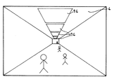
ここで魚眼レンズ13を用いたのは、天井面4に撮像装置1で撮像した球形映像を360度の視野角で天井面4の表示器5に表示できるからである。地下街又は大型複合商業ビル内にいる人に対して、床から天井面4へと鉛直方向に結んだ先の天頂を中心に、周囲の位置情報を認識することができる。図示するように、特徴的なビルに基づき、自分が現在どの位置にいるのかを容易に判断することができる。例えば、北北東の風景と西南西の風景は、ちょうど天頂を挟んで対向する位置に存在することを理解することができる。従って、天頂を中心にした天井面4に、周囲(屋外、室外、地上)の映像を表示することは、見る人にとって、略同じ視線方向の中で360度の位置情報を把握することが容易になる。
【0021】
テレビカメラ8は、この魚眼レンズ13に限定されず、屋外の風景を広範囲に撮像できるものであれば広角レンズに代えることも可能である。例えば、少数のテレビカメラ8で屋外の広範囲を撮像するときは、魚眼レンズ13を用いることが好ましい。一方、撮像装置1の配置間隔が狭いときは、広角レンズを用いることが好ましい。このように広角レンズを用いることで、屋外の映像を歪みのない状態で天井面4の表示器5に表示することができる。
【0022】
画像記録装置3は、撮像装置1で撮像された屋外画像情報とは別に、既に記録された案内画像情報を出力する装置である。例えば、この案内画像情報としては、表示器5に表示する緊急案内画像がある。この緊急案内画像は、地下街又は複合商業ビル等の屋内において火事等の災害が発生しているときに、その位置を歩行者に知らせる画像がある。または、地下街の工事中の位置等も知らせることに利用することができる。
【0023】
また、画像記録装置3には屋外への出口に関する道先案内画像情報を記録する。この道先案内画像情報は、図6に示すように、表示器5に屋外画像を表示しているときに所定時間毎に出口階段の位置や駅の方向を映し出す方式、又は出口階段の位置や駅の方向を表示するように屋外画像に重ねて表示する方式の何れの方法も採用することができる。
【0024】
表示器5は、画像処理装置2で処理された屋外画像情報及び画像記録装置3に記録された案内画像情報を、地下街又は大型の複合商業ビル内の天井面4に表示する装置である。表示器5は、複数のプラズマ液晶ディスプレイ装置14を天井面4に並べたものである。このように、表示器5は複数に分割して、地下街の天井面4又はビルの天井面4といった広い面積に合わせて表示することが可能である。
【0025】
表示器5は、この液晶ディスプレイ装置14に限定されず、天井面4に映像を広範囲に表示できる手段であればプロジェクター(図示していない)を配置することも可能である。このプロジェクターでは、広範囲に映像を表示することができるので、設備コストを低減させることができる。
【0026】
なお、本発明は、屋外の風景を地下街又は大型複合商業ビル内の天井面4に常時表示する構成であれば、上述した発明の実施の形態に限定されず、本発明の要旨を逸脱しない範囲で種々変更できることは勿論である。
【0027】
【発明の効果】
本発明の天井面ナビゲーション装置は、地下街又は大型の複合商業ビル内の天井面に撮像装置で撮像した屋外の映像を表示器に常時表示することができるので、地下街やビル内にいる人は、地上における現在地を正確に認識することができる。特に、屋外の実在方向の風景を映し出すときに、天井方向に必然的に空の映像や遠景等が映し出されることになるので、屋内の狭小な空間にいる人間にとって「開放感」を付与することにもなる。
【0028】
また、室内、屋内の空間にいるときには、屋外の天候情報が分からなかったが、本発明では天井面に空を含めた屋外の環境が映し出されるので、天候情報を提供することが可能になる。
【0029】
更に、映像情報を表示するときは、複数の人間が一度にかつ身長の高低に関係なく見ることができる場所であるにもかかわらず従来十分に活用されていなかったデッドスペースの天井面に、情報発信機能を付与し、この天井面を有効に活用することができる、等の効果がある。
【図面の簡単な説明】
【図1】本発明の天井面ナビゲーション装置の実施の形態を示すブロック図である。
【図2】撮像装置を街路灯に設けた状態を示す正面図である。
【図3】撮像装置を配電用路上機器に設けた状態を示す斜視図である。
【図4】撮像装置を電柱に設けた状態を示す斜視図である。
【図5】表示器を並べた天井面の一例を示す斜視図である。
【図6】天井面の表示器に道先案内画像を表示した一例を示す斜視図である。
【図7】魚眼レンズにより撮像した画像の一例を示す正面図である。
【符号の説明】
1 撮像装置
2 画像処理装置
3 画像記録装置
4 天井面
5 表示器
6 街路灯
7 電柱
8 テレビカメラ
9 路上変圧器
10 多回路開閉器(配電用路上機器)
11 低圧分岐箱
12 高圧キャビネット
13 魚眼レンズ
14 液晶ディスプレイ装置[0001]
BACKGROUND OF THE INVENTION
The present invention relates to a ceiling surface navigation device that displays an outdoor image or the like on a ceiling surface of an underground shopping area, transmits an outdoor situation to a person indoors, and guides a position of a stairway to escape to the outside in an emergency.
[0002]
[Prior art]
In recent years, underground malls and large-scale complex commercial buildings are increasing mainly in large cities. Many visitors to such underground malls and buildings can shop and eat while moving within the facility without being exposed to the weather. However, in underground malls and large buildings, you often lose your sense of direction, so you may be wondering where to go. Conventionally, only functional facilities such as “illumination lamps”, “speakers”, “disaster prevention sensors”, “ventilation vents” are provided on the ceiling. For this purpose, a guide map, a place name, character information indicating the name of the building, etc., and a map of the hall including the current location display are posted at predetermined locations in the underground shopping mall and buildings.
[0003]
On the other hand, in amusement parks such as theme parks, there have been proposed attractions that project various images such as animation, stories, or landscapes using large projectors on the entire wall surface or ceiling surface.
[0004]
[Problems to be solved by the invention]
However, text information indicating names and signs in underground shopping malls and complex commercial buildings can be easily understood by those who know them in advance, but it is easy for those who have come to the place for the first time. Could not be used. On the other hand, there was a problem that the destination could not be reached from similar names and assumptions, causing confusion.
[0005]
In addition, text information indicating names and signs attached to the walls of underground shopping malls and large commercial buildings was difficult to see for short people and children and was easy to overlook. The conventional character information attached to the wall surface has a problem that the navigation function is not sufficiently performed.
[0006]
On the other hand, local cities without high-rise buildings and old travelers have grasped geographical information by grasping the direction from the shape of the distant mountains (topography) and the position of the sun, that is, the irradiation angle of the sun. The sense of direction that humans have grasped instinctively and intuitively has not actually been used in urban life.
[0007]
Therefore, the inventor of the present invention projects an outdoor scenery in accordance with the direction of the actual scenery, thereby taking advantage of the sense of direction that humans originally have, and providing a navigation function that compensates for deficiencies due to character information, such as underground shopping malls. The present invention was invented so that it can be exhibited even indoors.
[0008]
The present invention has been developed to solve such problems. In other words, the object of the present invention is to display an outdoor video on the ceiling surface of an underground shopping area, and to make use of the sense of direction that humans originally have, to accurately determine the current location on the ground for people in the underground shopping mall or building. And providing a ceiling surface navigation device capable of guiding the position and direction of the stairway to the outside in an emergency.
[0009]
[Means for Solving the Problems]
According to the present invention, there is provided a ceiling surface navigation device that displays an outdoor image on an indoor ceiling surface (4), transmits an outdoor condition to an indoor person, and guides escape to the outside in an emergency. , while being placed at predetermined intervals in the outdoors, in order to capture a large number of position information of outdoor scenery, a plurality of imaging devices that extensively imaged by the imaging angle imprint the building to become a mark with an empty (1), In addition to the image processing device (2) that processes outdoor image information captured by each imaging device (1) and each outdoor image information captured by the imaging device (1), the guide image information that has already been recorded The image recording device (3) to output, the outdoor image information processed by the image processing device (2), and the guide image information recorded in the image recording device (3) are displayed on the indoor ceiling surface (4). A plurality of indicators (5) to be displayed on The provided, so that a person who is indoors can easily determine where it is in the current position, with respect to people in the indoor, around the zenith of connecting it above the floor and in the vertical direction to the ceiling surface (4) A ceiling surface navigation device characterized in that a plurality of displays (5) for displaying the outdoor image information in the vicinity thereof are arranged on the ceiling surface (4) so as to reproduce outdoor images over a wide range. Is provided.
[0010]
The imaging device (1) is a fish-eye lens attached to a street light (6), a rooftop of a building, an upper part of a signal light pole, an outdoor power pole (7), or an on-distribution equipment on the ground in underground facilities. (13) Or a television camera (8) provided with a wide-angle lens. It is preferable that emergency guide image information displayed only when necessary on the display (5) or roadside guide image information regarding an exit to the outdoors is recorded in the image recording device (3).
[0011]
The said display (5) arranges the plasma liquid crystal display device (14) on the said ceiling surface (4), or arrange | positions the projector in the indoor predetermined position.
[0012]
In the invention with the above-described configuration, the plurality of imaging devices (1) captures a building that becomes a landmark together with the sky, captures a large amount of position information of an outdoor landscape, and one image is captured by each imaging device (1). By displaying on the display (5), outdoor images can be reproduced in a wide range on the plurality of arranged displays (5). Therefore, with respect to people in the underground mall, it can Rukoto to recognize position information visible to the direction that connects the vertical direction to the ceiling surface (4) from the floor. That is, a person in the underground shopping area can accurately recognize the current location on the ground.
Also, the fisheye lens imaging apparatus of (13) a TV camera (8) (1), this viewing angle of 360 degrees captured spherical image, ceiling surface a larger number of position information indicator (4) ( 5).
[0013]
In the display (5), a plurality of plasma liquid crystal display devices (14) are arranged on the ceiling surface (4) or a plurality of projectors are arranged, so that an outdoor image is divided into a plurality of displays on the display (5). By doing so, it is displayed in accordance with a wide area such as the ceiling surface (4) of the underground shopping mall or the ceiling surface (4) of the building.
[0014]
DETAILED DESCRIPTION OF THE INVENTION
Hereinafter, preferred embodiments of the present invention will be described with reference to the drawings.
FIG. 1 is a block diagram showing an embodiment of a ceiling navigation device of the present invention. FIG. 2 is a front view showing a state in which the imaging device is provided on the street lamp. FIG. 3 is a perspective view illustrating a state in which the imaging device is provided in the on-road device for distribution. FIG. 4 is a perspective view showing a state in which the imaging device is provided on the utility pole. FIG. 5 is a perspective view showing an example of a ceiling surface on which displays are arranged. FIG. 6 is a perspective view showing an example in which a road guide image is displayed on a display on the ceiling surface.
The ceiling navigation device of the present invention mainly includes a plurality of imaging devices 1 that capture a wide range of outdoor scenery, an image processing device 2 that processes the image information, and an image that has already been recorded. An image recording
[0015]
The imaging device 1 is a device in which a
[0016]
In the upper part of the underground shopping center, undergrounding of electric wires is promoted, but some of the facilities are on the ground even if they are underground related facilities. For example, as shown in FIG. 3, on-road devices for distribution such as a road transformer 9, a
[0017]
Moreover, the imaging device 1 can also attach the
[0018]
Furthermore, if it is the structure which can image the outdoor scenery on the road in a wide range with the
[0019]
FIG. 7 is a front view showing an example of an image captured by a fisheye lens.
The imaging apparatus 1 includes a
[0020]
The reason why the
[0021]
The
[0022]
The
[0023]
The
[0024]
Display device 5, the guidance image information recorded outdoors image information and the
[0025]
The display 5 is not limited to the liquid
[0026]
It should be noted that the present invention is not limited to the above-described embodiment of the present invention as long as the outdoor landscape is always displayed on the
[0027]
【The invention's effect】
Because the ceiling surface navigation apparatus of the present invention, it is possible to always display the outdoor video imaged by the imaging device on a ceiling surface in the underground shopping center or large commercial complex building on a display, a person who is in the underground shopping area or building, The current location on the ground can be accurately recognized. In particular, when projecting outdoor scenery in the actual direction, an image of the sky, distant view, etc. will inevitably be projected in the ceiling direction, giving a sense of openness to people in a small indoor space. It also becomes.
[0028]
Further, when the user is in an indoor or indoor space, outdoor weather information is not known. However, in the present invention, the outdoor environment including the sky is projected on the ceiling surface, so that weather information can be provided.
[0029]
Furthermore, when displaying video information, the information is placed on the ceiling surface of dead space that has not been fully utilized in the past, even though it is a place where multiple people can see at once, regardless of height. There is an effect that a transmission function is provided and the ceiling surface can be effectively used.
[Brief description of the drawings]
FIG. 1 is a block diagram showing an embodiment of a ceiling navigation device of the present invention.
FIG. 2 is a front view showing a state in which the imaging device is provided on a street lamp.
FIG. 3 is a perspective view illustrating a state in which the imaging device is provided in a device on the power distribution road.
FIG. 4 is a perspective view showing a state in which the imaging device is provided on the utility pole.
FIG. 5 is a perspective view showing an example of a ceiling surface on which displays are arranged.
FIG. 6 is a perspective view showing an example in which a road guide image is displayed on a display device on a ceiling surface.
FIG. 7 is a front view showing an example of an image captured by a fisheye lens.
[Explanation of symbols]
DESCRIPTION OF SYMBOLS 1 Imaging device 2
11 Low
Claims (13)
屋外に所定間隔毎に設置されると共に、屋外の風景の多数の位置情報を捉えるために、空と共に目印になるビルを写し込むように広範囲に撮像する複数の撮像装置(1)と、
各撮像装置(1)によって撮像された屋外画像情報を処理する画像処理装置(2)と、
前記撮像装置(1)で撮像された各屋外画像情報とは別に、既に記録された案内画像情報を出力する画像記録装置(3)と、
前記画像処理装置(2)で処理された各屋外画像情報、及び前記画像記録装置(3)に記録された案内画像情報を、屋内の天井面(4)に表示する複数の表示器(5)と、を備え、
屋内にいる人が現在どの位置にいるのかを容易に判断できるように、床から天井面(4)へと鉛直方向に結んだ方向を撮像した前記屋外画像情報を表示する表示器(5)を、前記天井面(4)に複数並べて屋外の映像を広範囲に再現するように構成した、ことを特徴とする天井面ナビゲーション装置。 A ceiling surface navigation device that displays an outdoor video on an indoor ceiling surface (4), transmits the outdoor situation to a person indoors, and guides escape to the outside in an emergency,
A plurality of imaging devices (1) that are installed outdoors at predetermined intervals and capture a wide range of images of buildings that serve as landmarks together with the sky in order to capture a large amount of position information of outdoor scenery;
An image processing device (2) for processing outdoor image information captured by each imaging device (1);
In addition to each outdoor image information imaged by the imaging device (1), an image recording device (3) for outputting already recorded guide image information;
A plurality of indicators (5) for displaying each outdoor image information processed by the image processing device (2) and guide image information recorded in the image recording device (3) on an indoor ceiling surface (4). And comprising
A display (5) for displaying the outdoor image information obtained by imaging the direction connected from the floor to the ceiling surface (4) in a vertical direction so that it can be easily determined where the person who is indoors is currently located. A ceiling surface navigation device , wherein a plurality of outdoor images are arranged side by side on the ceiling surface (4) to reproduce a wide range of outdoor images .
Priority Applications (1)
| Application Number | Priority Date | Filing Date | Title |
|---|---|---|---|
| JP2002235433A JP4266592B2 (en) | 2002-08-13 | 2002-08-13 | Ceiling surface navigation device |
Applications Claiming Priority (1)
| Application Number | Priority Date | Filing Date | Title |
|---|---|---|---|
| JP2002235433A JP4266592B2 (en) | 2002-08-13 | 2002-08-13 | Ceiling surface navigation device |
Publications (2)
| Publication Number | Publication Date |
|---|---|
| JP2004077634A JP2004077634A (en) | 2004-03-11 |
| JP4266592B2 true JP4266592B2 (en) | 2009-05-20 |
Family
ID=32019922
Family Applications (1)
| Application Number | Title | Priority Date | Filing Date |
|---|---|---|---|
| JP2002235433A Expired - Fee Related JP4266592B2 (en) | 2002-08-13 | 2002-08-13 | Ceiling surface navigation device |
Country Status (1)
| Country | Link |
|---|---|
| JP (1) | JP4266592B2 (en) |
Families Citing this family (3)
| Publication number | Priority date | Publication date | Assignee | Title |
|---|---|---|---|---|
| JP5559467B2 (en) * | 2008-08-04 | 2014-07-23 | 肇 川上 | Building |
| JP5345872B2 (en) * | 2009-02-26 | 2013-11-20 | 中国電力株式会社 | High speed communication system |
| JP2011075848A (en) * | 2009-09-30 | 2011-04-14 | Tokyo Metropolitan Government | Information display system |
-
2002
- 2002-08-13 JP JP2002235433A patent/JP4266592B2/en not_active Expired - Fee Related
Also Published As
| Publication number | Publication date |
|---|---|
| JP2004077634A (en) | 2004-03-11 |
Similar Documents
| Publication | Publication Date | Title |
|---|---|---|
| CN211827862U (en) | Multimedia interactive electronic sand table | |
| KR20180056880A (en) | CCTV integration pole | |
| JP2008117166A (en) | Annunciator arrangement and air conditioner | |
| JP2010102279A (en) | Security safety system by banner advertisement and fee system bus stop sign | |
| WO2019207954A1 (en) | Information processing device, information processing method, and information processing program | |
| JP4266592B2 (en) | Ceiling surface navigation device | |
| JP2016208255A (en) | Movable projection device | |
| CA1097524A (en) | Drive in theatre | |
| JP2005277670A (en) | Omniazimuth video image generating apparatus, map interlocked omniazimuth video recording / display apparatus, and map interlocked omniazimuth video image utilizing apparatus | |
| WO2010107252A2 (en) | Pedestrian signal lamp device | |
| CN211718765U (en) | Unmanned aerial vehicle flight control system simulating urban space | |
| KR100967900B1 (en) | System for providing infomation of intersection | |
| CN216623720U (en) | Digital corridor of digital exhibition hall | |
| JP2019161652A (en) | Mobile projection apparatus and projection system | |
| CN109972662A (en) | Intelligent well cover | |
| KR200484267Y1 (en) | Integrated Apparatus For Security | |
| US20220236940A1 (en) | Portable dynamic display apparatus | |
| JP3535467B2 (en) | Imaging information providing device | |
| KR101375522B1 (en) | Access to the central bus lane guidance system | |
| JP4098062B2 (en) | Video projection system | |
| JP2004096794A (en) | Image pick-up information providing system | |
| JP2002163765A (en) | Geographical information processor | |
| JP2017147309A (en) | Self-standing type security device | |
| JP2005309826A (en) | Multifunctional crime prevention light and crime prevention light system having the same | |
| CN108986640A (en) | Laser guidance electronic information 3-D map |
Legal Events
| Date | Code | Title | Description |
|---|---|---|---|
| A621 | Written request for application examination |
Free format text: JAPANESE INTERMEDIATE CODE: A621 Effective date: 20050729 |
|
| A977 | Report on retrieval |
Free format text: JAPANESE INTERMEDIATE CODE: A971007 Effective date: 20080422 |
|
| A131 | Notification of reasons for refusal |
Free format text: JAPANESE INTERMEDIATE CODE: A131 Effective date: 20080428 |
|
| A521 | Written amendment |
Free format text: JAPANESE INTERMEDIATE CODE: A523 Effective date: 20080626 |
|
| TRDD | Decision of grant or rejection written | ||
| A01 | Written decision to grant a patent or to grant a registration (utility model) |
Free format text: JAPANESE INTERMEDIATE CODE: A01 Effective date: 20090217 |
|
| A01 | Written decision to grant a patent or to grant a registration (utility model) |
Free format text: JAPANESE INTERMEDIATE CODE: A01 |
|
| A61 | First payment of annual fees (during grant procedure) |
Free format text: JAPANESE INTERMEDIATE CODE: A61 Effective date: 20090217 |
|
| R150 | Certificate of patent or registration of utility model |
Ref document number: 4266592 Country of ref document: JP Free format text: JAPANESE INTERMEDIATE CODE: R150 Free format text: JAPANESE INTERMEDIATE CODE: R150 |
|
| FPAY | Renewal fee payment (event date is renewal date of database) |
Free format text: PAYMENT UNTIL: 20120227 Year of fee payment: 3 |
|
| FPAY | Renewal fee payment (event date is renewal date of database) |
Free format text: PAYMENT UNTIL: 20120227 Year of fee payment: 3 |
|
| FPAY | Renewal fee payment (event date is renewal date of database) |
Free format text: PAYMENT UNTIL: 20120227 Year of fee payment: 3 |
|
| FPAY | Renewal fee payment (event date is renewal date of database) |
Free format text: PAYMENT UNTIL: 20120227 Year of fee payment: 3 |
|
| FPAY | Renewal fee payment (event date is renewal date of database) |
Free format text: PAYMENT UNTIL: 20130227 Year of fee payment: 4 |
|
| R250 | Receipt of annual fees |
Free format text: JAPANESE INTERMEDIATE CODE: R250 |
|
| FPAY | Renewal fee payment (event date is renewal date of database) |
Free format text: PAYMENT UNTIL: 20130227 Year of fee payment: 4 |
|
| FPAY | Renewal fee payment (event date is renewal date of database) |
Free format text: PAYMENT UNTIL: 20130227 Year of fee payment: 4 |
|
| FPAY | Renewal fee payment (event date is renewal date of database) |
Free format text: PAYMENT UNTIL: 20140227 Year of fee payment: 5 |
|
| R250 | Receipt of annual fees |
Free format text: JAPANESE INTERMEDIATE CODE: R250 |
|
| R250 | Receipt of annual fees |
Free format text: JAPANESE INTERMEDIATE CODE: R250 |
|
| R250 | Receipt of annual fees |
Free format text: JAPANESE INTERMEDIATE CODE: R250 |
|
| R250 | Receipt of annual fees |
Free format text: JAPANESE INTERMEDIATE CODE: R250 |
|
| R250 | Receipt of annual fees |
Free format text: JAPANESE INTERMEDIATE CODE: R250 |
|
| R250 | Receipt of annual fees |
Free format text: JAPANESE INTERMEDIATE CODE: R250 |
|
| LAPS | Cancellation because of no payment of annual fees |