JP4265572B2 - POWER OUTPUT DEVICE, VEHICLE MOUNTING THE SAME, AND METHOD FOR CONTROLLING POWER OUTPUT DEVICE - Google Patents
POWER OUTPUT DEVICE, VEHICLE MOUNTING THE SAME, AND METHOD FOR CONTROLLING POWER OUTPUT DEVICE Download PDFInfo
- Publication number
- JP4265572B2 JP4265572B2 JP2005161616A JP2005161616A JP4265572B2 JP 4265572 B2 JP4265572 B2 JP 4265572B2 JP 2005161616 A JP2005161616 A JP 2005161616A JP 2005161616 A JP2005161616 A JP 2005161616A JP 4265572 B2 JP4265572 B2 JP 4265572B2
- Authority
- JP
- Japan
- Prior art keywords
- shaft side
- internal combustion
- rotational speed
- combustion engine
- power
- Prior art date
- Legal status (The legal status is an assumption and is not a legal conclusion. Google has not performed a legal analysis and makes no representation as to the accuracy of the status listed.)
- Active
Links
- 238000000034 method Methods 0.000 title claims description 24
- 230000005540 biological transmission Effects 0.000 claims description 116
- 238000002485 combustion reaction Methods 0.000 claims description 115
- 230000001133 acceleration Effects 0.000 claims description 83
- 230000006399 behavior Effects 0.000 claims description 28
- 238000012937 correction Methods 0.000 claims description 22
- 239000012530 fluid Substances 0.000 claims description 16
- 238000001514 detection method Methods 0.000 claims description 9
- 238000013459 approach Methods 0.000 claims description 7
- 230000003111 delayed effect Effects 0.000 claims description 3
- 239000003921 oil Substances 0.000 description 36
- 238000010586 diagram Methods 0.000 description 7
- 238000012545 processing Methods 0.000 description 7
- 230000035939 shock Effects 0.000 description 6
- 238000004891 communication Methods 0.000 description 5
- 230000001360 synchronised effect Effects 0.000 description 5
- 230000000979 retarding effect Effects 0.000 description 4
- 230000007423 decrease Effects 0.000 description 3
- 230000000694 effects Effects 0.000 description 3
- 239000000446 fuel Substances 0.000 description 3
- 239000007858 starting material Substances 0.000 description 3
- 230000003247 decreasing effect Effects 0.000 description 2
- 230000000994 depressogenic effect Effects 0.000 description 2
- 238000004880 explosion Methods 0.000 description 2
- 239000010720 hydraulic oil Substances 0.000 description 2
- 238000002347 injection Methods 0.000 description 2
- 239000007924 injection Substances 0.000 description 2
- 239000004215 Carbon black (E152) Substances 0.000 description 1
- UNPLRYRWJLTVAE-UHFFFAOYSA-N Cloperastine hydrochloride Chemical compound Cl.C1=CC(Cl)=CC=C1C(C=1C=CC=CC=1)OCCN1CCCCC1 UNPLRYRWJLTVAE-UHFFFAOYSA-N 0.000 description 1
- 230000032683 aging Effects 0.000 description 1
- 238000005265 energy consumption Methods 0.000 description 1
- 238000002474 experimental method Methods 0.000 description 1
- 229930195733 hydrocarbon Natural products 0.000 description 1
- 150000002430 hydrocarbons Chemical class 0.000 description 1
- 238000004519 manufacturing process Methods 0.000 description 1
- 238000012986 modification Methods 0.000 description 1
- 230000004048 modification Effects 0.000 description 1
- 238000002360 preparation method Methods 0.000 description 1
- 239000007787 solid Substances 0.000 description 1
Images


Classifications
-
- B—PERFORMING OPERATIONS; TRANSPORTING
- B60—VEHICLES IN GENERAL
- B60W—CONJOINT CONTROL OF VEHICLE SUB-UNITS OF DIFFERENT TYPE OR DIFFERENT FUNCTION; CONTROL SYSTEMS SPECIALLY ADAPTED FOR HYBRID VEHICLES; ROAD VEHICLE DRIVE CONTROL SYSTEMS FOR PURPOSES NOT RELATED TO THE CONTROL OF A PARTICULAR SUB-UNIT
- B60W20/00—Control systems specially adapted for hybrid vehicles
- B60W20/40—Controlling the engagement or disengagement of prime movers, e.g. for transition between prime movers
-
- B—PERFORMING OPERATIONS; TRANSPORTING
- B60—VEHICLES IN GENERAL
- B60K—ARRANGEMENT OR MOUNTING OF PROPULSION UNITS OR OF TRANSMISSIONS IN VEHICLES; ARRANGEMENT OR MOUNTING OF PLURAL DIVERSE PRIME-MOVERS IN VEHICLES; AUXILIARY DRIVES FOR VEHICLES; INSTRUMENTATION OR DASHBOARDS FOR VEHICLES; ARRANGEMENTS IN CONNECTION WITH COOLING, AIR INTAKE, GAS EXHAUST OR FUEL SUPPLY OF PROPULSION UNITS IN VEHICLES
- B60K6/00—Arrangement or mounting of plural diverse prime-movers for mutual or common propulsion, e.g. hybrid propulsion systems comprising electric motors and internal combustion engines ; Control systems therefor, i.e. systems controlling two or more prime movers, or controlling one of these prime movers and any of the transmission, drive or drive units Informative references: mechanical gearings with secondary electric drive F16H3/72; arrangements for handling mechanical energy structurally associated with the dynamo-electric machine H02K7/00; machines comprising structurally interrelated motor and generator parts H02K51/00; dynamo-electric machines not otherwise provided for in H02K see H02K99/00
- B60K6/20—Arrangement or mounting of plural diverse prime-movers for mutual or common propulsion, e.g. hybrid propulsion systems comprising electric motors and internal combustion engines ; Control systems therefor, i.e. systems controlling two or more prime movers, or controlling one of these prime movers and any of the transmission, drive or drive units Informative references: mechanical gearings with secondary electric drive F16H3/72; arrangements for handling mechanical energy structurally associated with the dynamo-electric machine H02K7/00; machines comprising structurally interrelated motor and generator parts H02K51/00; dynamo-electric machines not otherwise provided for in H02K see H02K99/00 the prime-movers consisting of electric motors and internal combustion engines, e.g. HEVs
- B60K6/50—Architecture of the driveline characterised by arrangement or kind of transmission units
- B60K6/52—Driving a plurality of drive axles, e.g. four-wheel drive
-
- B—PERFORMING OPERATIONS; TRANSPORTING
- B60—VEHICLES IN GENERAL
- B60K—ARRANGEMENT OR MOUNTING OF PROPULSION UNITS OR OF TRANSMISSIONS IN VEHICLES; ARRANGEMENT OR MOUNTING OF PLURAL DIVERSE PRIME-MOVERS IN VEHICLES; AUXILIARY DRIVES FOR VEHICLES; INSTRUMENTATION OR DASHBOARDS FOR VEHICLES; ARRANGEMENTS IN CONNECTION WITH COOLING, AIR INTAKE, GAS EXHAUST OR FUEL SUPPLY OF PROPULSION UNITS IN VEHICLES
- B60K6/00—Arrangement or mounting of plural diverse prime-movers for mutual or common propulsion, e.g. hybrid propulsion systems comprising electric motors and internal combustion engines ; Control systems therefor, i.e. systems controlling two or more prime movers, or controlling one of these prime movers and any of the transmission, drive or drive units Informative references: mechanical gearings with secondary electric drive F16H3/72; arrangements for handling mechanical energy structurally associated with the dynamo-electric machine H02K7/00; machines comprising structurally interrelated motor and generator parts H02K51/00; dynamo-electric machines not otherwise provided for in H02K see H02K99/00
- B60K6/20—Arrangement or mounting of plural diverse prime-movers for mutual or common propulsion, e.g. hybrid propulsion systems comprising electric motors and internal combustion engines ; Control systems therefor, i.e. systems controlling two or more prime movers, or controlling one of these prime movers and any of the transmission, drive or drive units Informative references: mechanical gearings with secondary electric drive F16H3/72; arrangements for handling mechanical energy structurally associated with the dynamo-electric machine H02K7/00; machines comprising structurally interrelated motor and generator parts H02K51/00; dynamo-electric machines not otherwise provided for in H02K see H02K99/00 the prime-movers consisting of electric motors and internal combustion engines, e.g. HEVs
- B60K6/50—Architecture of the driveline characterised by arrangement or kind of transmission units
- B60K6/54—Transmission for changing ratio
- B60K6/543—Transmission for changing ratio the transmission being a continuously variable transmission
-
- B—PERFORMING OPERATIONS; TRANSPORTING
- B60—VEHICLES IN GENERAL
- B60W—CONJOINT CONTROL OF VEHICLE SUB-UNITS OF DIFFERENT TYPE OR DIFFERENT FUNCTION; CONTROL SYSTEMS SPECIALLY ADAPTED FOR HYBRID VEHICLES; ROAD VEHICLE DRIVE CONTROL SYSTEMS FOR PURPOSES NOT RELATED TO THE CONTROL OF A PARTICULAR SUB-UNIT
- B60W10/00—Conjoint control of vehicle sub-units of different type or different function
- B60W10/02—Conjoint control of vehicle sub-units of different type or different function including control of driveline clutches
-
- B—PERFORMING OPERATIONS; TRANSPORTING
- B60—VEHICLES IN GENERAL
- B60W—CONJOINT CONTROL OF VEHICLE SUB-UNITS OF DIFFERENT TYPE OR DIFFERENT FUNCTION; CONTROL SYSTEMS SPECIALLY ADAPTED FOR HYBRID VEHICLES; ROAD VEHICLE DRIVE CONTROL SYSTEMS FOR PURPOSES NOT RELATED TO THE CONTROL OF A PARTICULAR SUB-UNIT
- B60W10/00—Conjoint control of vehicle sub-units of different type or different function
- B60W10/04—Conjoint control of vehicle sub-units of different type or different function including control of propulsion units
- B60W10/06—Conjoint control of vehicle sub-units of different type or different function including control of propulsion units including control of combustion engines
-
- B—PERFORMING OPERATIONS; TRANSPORTING
- B60—VEHICLES IN GENERAL
- B60W—CONJOINT CONTROL OF VEHICLE SUB-UNITS OF DIFFERENT TYPE OR DIFFERENT FUNCTION; CONTROL SYSTEMS SPECIALLY ADAPTED FOR HYBRID VEHICLES; ROAD VEHICLE DRIVE CONTROL SYSTEMS FOR PURPOSES NOT RELATED TO THE CONTROL OF A PARTICULAR SUB-UNIT
- B60W10/00—Conjoint control of vehicle sub-units of different type or different function
- B60W10/04—Conjoint control of vehicle sub-units of different type or different function including control of propulsion units
- B60W10/08—Conjoint control of vehicle sub-units of different type or different function including control of propulsion units including control of electric propulsion units, e.g. motors or generators
-
- B—PERFORMING OPERATIONS; TRANSPORTING
- B60—VEHICLES IN GENERAL
- B60W—CONJOINT CONTROL OF VEHICLE SUB-UNITS OF DIFFERENT TYPE OR DIFFERENT FUNCTION; CONTROL SYSTEMS SPECIALLY ADAPTED FOR HYBRID VEHICLES; ROAD VEHICLE DRIVE CONTROL SYSTEMS FOR PURPOSES NOT RELATED TO THE CONTROL OF A PARTICULAR SUB-UNIT
- B60W10/00—Conjoint control of vehicle sub-units of different type or different function
- B60W10/10—Conjoint control of vehicle sub-units of different type or different function including control of change-speed gearings
- B60W10/101—Infinitely variable gearings
- B60W10/107—Infinitely variable gearings with endless flexible members
-
- B—PERFORMING OPERATIONS; TRANSPORTING
- B60—VEHICLES IN GENERAL
- B60W—CONJOINT CONTROL OF VEHICLE SUB-UNITS OF DIFFERENT TYPE OR DIFFERENT FUNCTION; CONTROL SYSTEMS SPECIALLY ADAPTED FOR HYBRID VEHICLES; ROAD VEHICLE DRIVE CONTROL SYSTEMS FOR PURPOSES NOT RELATED TO THE CONTROL OF A PARTICULAR SUB-UNIT
- B60W30/00—Purposes of road vehicle drive control systems not related to the control of a particular sub-unit, e.g. of systems using conjoint control of vehicle sub-units
- B60W30/18—Propelling the vehicle
- B60W30/18009—Propelling the vehicle related to particular drive situations
- B60W30/18027—Drive off, accelerating from standstill
-
- B—PERFORMING OPERATIONS; TRANSPORTING
- B60—VEHICLES IN GENERAL
- B60W—CONJOINT CONTROL OF VEHICLE SUB-UNITS OF DIFFERENT TYPE OR DIFFERENT FUNCTION; CONTROL SYSTEMS SPECIALLY ADAPTED FOR HYBRID VEHICLES; ROAD VEHICLE DRIVE CONTROL SYSTEMS FOR PURPOSES NOT RELATED TO THE CONTROL OF A PARTICULAR SUB-UNIT
- B60W30/00—Purposes of road vehicle drive control systems not related to the control of a particular sub-unit, e.g. of systems using conjoint control of vehicle sub-units
- B60W30/18—Propelling the vehicle
- B60W30/192—Mitigating problems related to power-up or power-down of the driveline, e.g. start-up of a cold engine
- B60W30/194—Mitigating problems related to power-up or power-down of the driveline, e.g. start-up of a cold engine related to low temperature conditions, e.g. high viscosity of hydraulic fluid
-
- F—MECHANICAL ENGINEERING; LIGHTING; HEATING; WEAPONS; BLASTING
- F02—COMBUSTION ENGINES; HOT-GAS OR COMBUSTION-PRODUCT ENGINE PLANTS
- F02D—CONTROLLING COMBUSTION ENGINES
- F02D31/00—Use of speed-sensing governors to control combustion engines, not otherwise provided for
- F02D31/001—Electric control of rotation speed
- F02D31/002—Electric control of rotation speed controlling air supply
-
- F—MECHANICAL ENGINEERING; LIGHTING; HEATING; WEAPONS; BLASTING
- F02—COMBUSTION ENGINES; HOT-GAS OR COMBUSTION-PRODUCT ENGINE PLANTS
- F02P—IGNITION, OTHER THAN COMPRESSION IGNITION, FOR INTERNAL-COMBUSTION ENGINES; TESTING OF IGNITION TIMING IN COMPRESSION-IGNITION ENGINES
- F02P5/00—Advancing or retarding ignition; Control therefor
- F02P5/04—Advancing or retarding ignition; Control therefor automatically, as a function of the working conditions of the engine or vehicle or of the atmospheric conditions
- F02P5/145—Advancing or retarding ignition; Control therefor automatically, as a function of the working conditions of the engine or vehicle or of the atmospheric conditions using electrical means
- F02P5/15—Digital data processing
- F02P5/1502—Digital data processing using one central computing unit
- F02P5/1506—Digital data processing using one central computing unit with particular means during starting
-
- B—PERFORMING OPERATIONS; TRANSPORTING
- B60—VEHICLES IN GENERAL
- B60L—PROPULSION OF ELECTRICALLY-PROPELLED VEHICLES; SUPPLYING ELECTRIC POWER FOR AUXILIARY EQUIPMENT OF ELECTRICALLY-PROPELLED VEHICLES; ELECTRODYNAMIC BRAKE SYSTEMS FOR VEHICLES IN GENERAL; MAGNETIC SUSPENSION OR LEVITATION FOR VEHICLES; MONITORING OPERATING VARIABLES OF ELECTRICALLY-PROPELLED VEHICLES; ELECTRIC SAFETY DEVICES FOR ELECTRICALLY-PROPELLED VEHICLES
- B60L2240/00—Control parameters of input or output; Target parameters
- B60L2240/40—Drive Train control parameters
- B60L2240/44—Drive Train control parameters related to combustion engines
- B60L2240/441—Speed
-
- B—PERFORMING OPERATIONS; TRANSPORTING
- B60—VEHICLES IN GENERAL
- B60L—PROPULSION OF ELECTRICALLY-PROPELLED VEHICLES; SUPPLYING ELECTRIC POWER FOR AUXILIARY EQUIPMENT OF ELECTRICALLY-PROPELLED VEHICLES; ELECTRODYNAMIC BRAKE SYSTEMS FOR VEHICLES IN GENERAL; MAGNETIC SUSPENSION OR LEVITATION FOR VEHICLES; MONITORING OPERATING VARIABLES OF ELECTRICALLY-PROPELLED VEHICLES; ELECTRIC SAFETY DEVICES FOR ELECTRICALLY-PROPELLED VEHICLES
- B60L2240/00—Control parameters of input or output; Target parameters
- B60L2240/40—Drive Train control parameters
- B60L2240/48—Drive Train control parameters related to transmissions
- B60L2240/486—Operating parameters
-
- B—PERFORMING OPERATIONS; TRANSPORTING
- B60—VEHICLES IN GENERAL
- B60W—CONJOINT CONTROL OF VEHICLE SUB-UNITS OF DIFFERENT TYPE OR DIFFERENT FUNCTION; CONTROL SYSTEMS SPECIALLY ADAPTED FOR HYBRID VEHICLES; ROAD VEHICLE DRIVE CONTROL SYSTEMS FOR PURPOSES NOT RELATED TO THE CONTROL OF A PARTICULAR SUB-UNIT
- B60W20/00—Control systems specially adapted for hybrid vehicles
-
- B—PERFORMING OPERATIONS; TRANSPORTING
- B60—VEHICLES IN GENERAL
- B60W—CONJOINT CONTROL OF VEHICLE SUB-UNITS OF DIFFERENT TYPE OR DIFFERENT FUNCTION; CONTROL SYSTEMS SPECIALLY ADAPTED FOR HYBRID VEHICLES; ROAD VEHICLE DRIVE CONTROL SYSTEMS FOR PURPOSES NOT RELATED TO THE CONTROL OF A PARTICULAR SUB-UNIT
- B60W2510/00—Input parameters relating to a particular sub-units
- B60W2510/06—Combustion engines, Gas turbines
- B60W2510/0638—Engine speed
-
- B—PERFORMING OPERATIONS; TRANSPORTING
- B60—VEHICLES IN GENERAL
- B60W—CONJOINT CONTROL OF VEHICLE SUB-UNITS OF DIFFERENT TYPE OR DIFFERENT FUNCTION; CONTROL SYSTEMS SPECIALLY ADAPTED FOR HYBRID VEHICLES; ROAD VEHICLE DRIVE CONTROL SYSTEMS FOR PURPOSES NOT RELATED TO THE CONTROL OF A PARTICULAR SUB-UNIT
- B60W2510/00—Input parameters relating to a particular sub-units
- B60W2510/10—Change speed gearings
- B60W2510/1015—Input shaft speed, e.g. turbine speed
-
- B—PERFORMING OPERATIONS; TRANSPORTING
- B60—VEHICLES IN GENERAL
- B60W—CONJOINT CONTROL OF VEHICLE SUB-UNITS OF DIFFERENT TYPE OR DIFFERENT FUNCTION; CONTROL SYSTEMS SPECIALLY ADAPTED FOR HYBRID VEHICLES; ROAD VEHICLE DRIVE CONTROL SYSTEMS FOR PURPOSES NOT RELATED TO THE CONTROL OF A PARTICULAR SUB-UNIT
- B60W2520/00—Input parameters relating to overall vehicle dynamics
- B60W2520/10—Longitudinal speed
- B60W2520/105—Longitudinal acceleration
-
- B—PERFORMING OPERATIONS; TRANSPORTING
- B60—VEHICLES IN GENERAL
- B60W—CONJOINT CONTROL OF VEHICLE SUB-UNITS OF DIFFERENT TYPE OR DIFFERENT FUNCTION; CONTROL SYSTEMS SPECIALLY ADAPTED FOR HYBRID VEHICLES; ROAD VEHICLE DRIVE CONTROL SYSTEMS FOR PURPOSES NOT RELATED TO THE CONTROL OF A PARTICULAR SUB-UNIT
- B60W2720/00—Output or target parameters relating to overall vehicle dynamics
- B60W2720/10—Longitudinal speed
- B60W2720/106—Longitudinal acceleration
-
- F—MECHANICAL ENGINEERING; LIGHTING; HEATING; WEAPONS; BLASTING
- F16—ENGINEERING ELEMENTS AND UNITS; GENERAL MEASURES FOR PRODUCING AND MAINTAINING EFFECTIVE FUNCTIONING OF MACHINES OR INSTALLATIONS; THERMAL INSULATION IN GENERAL
- F16H—GEARING
- F16H61/00—Control functions within control units of change-speed- or reversing-gearings for conveying rotary motion ; Control of exclusively fluid gearing, friction gearing, gearings with endless flexible members or other particular types of gearing
- F16H61/66—Control functions within control units of change-speed- or reversing-gearings for conveying rotary motion ; Control of exclusively fluid gearing, friction gearing, gearings with endless flexible members or other particular types of gearing specially adapted for continuously variable gearings
- F16H61/662—Control functions within control units of change-speed- or reversing-gearings for conveying rotary motion ; Control of exclusively fluid gearing, friction gearing, gearings with endless flexible members or other particular types of gearing specially adapted for continuously variable gearings with endless flexible members
- F16H61/66254—Control functions within control units of change-speed- or reversing-gearings for conveying rotary motion ; Control of exclusively fluid gearing, friction gearing, gearings with endless flexible members or other particular types of gearing specially adapted for continuously variable gearings with endless flexible members controlling of shifting being influenced by a signal derived from the engine and the main coupling
- F16H61/66259—Control functions within control units of change-speed- or reversing-gearings for conveying rotary motion ; Control of exclusively fluid gearing, friction gearing, gearings with endless flexible members or other particular types of gearing specially adapted for continuously variable gearings with endless flexible members controlling of shifting being influenced by a signal derived from the engine and the main coupling using electrical or electronical sensing or control means
-
- Y—GENERAL TAGGING OF NEW TECHNOLOGICAL DEVELOPMENTS; GENERAL TAGGING OF CROSS-SECTIONAL TECHNOLOGIES SPANNING OVER SEVERAL SECTIONS OF THE IPC; TECHNICAL SUBJECTS COVERED BY FORMER USPC CROSS-REFERENCE ART COLLECTIONS [XRACs] AND DIGESTS
- Y02—TECHNOLOGIES OR APPLICATIONS FOR MITIGATION OR ADAPTATION AGAINST CLIMATE CHANGE
- Y02T—CLIMATE CHANGE MITIGATION TECHNOLOGIES RELATED TO TRANSPORTATION
- Y02T10/00—Road transport of goods or passengers
- Y02T10/10—Internal combustion engine [ICE] based vehicles
- Y02T10/40—Engine management systems
-
- Y—GENERAL TAGGING OF NEW TECHNOLOGICAL DEVELOPMENTS; GENERAL TAGGING OF CROSS-SECTIONAL TECHNOLOGIES SPANNING OVER SEVERAL SECTIONS OF THE IPC; TECHNICAL SUBJECTS COVERED BY FORMER USPC CROSS-REFERENCE ART COLLECTIONS [XRACs] AND DIGESTS
- Y02—TECHNOLOGIES OR APPLICATIONS FOR MITIGATION OR ADAPTATION AGAINST CLIMATE CHANGE
- Y02T—CLIMATE CHANGE MITIGATION TECHNOLOGIES RELATED TO TRANSPORTATION
- Y02T10/00—Road transport of goods or passengers
- Y02T10/60—Other road transportation technologies with climate change mitigation effect
- Y02T10/62—Hybrid vehicles
Landscapes
- Engineering & Computer Science (AREA)
- Chemical & Material Sciences (AREA)
- Combustion & Propulsion (AREA)
- Mechanical Engineering (AREA)
- Transportation (AREA)
- Automation & Control Theory (AREA)
- General Engineering & Computer Science (AREA)
- Theoretical Computer Science (AREA)
- Signal Processing (AREA)
- Control Of Driving Devices And Active Controlling Of Vehicle (AREA)
- Hybrid Electric Vehicles (AREA)
- Electric Propulsion And Braking For Vehicles (AREA)
- Control Of Transmission Device (AREA)
- Control Of Vehicle Engines Or Engines For Specific Uses (AREA)
- Hydraulic Clutches, Magnetic Clutches, Fluid Clutches, And Fluid Joints (AREA)
Description
本発明は、動力出力装置およびこれを搭載する車両並びに動力出力装置の制御方法に関する。 The present invention relates to a power output apparatus, a vehicle on which the power output apparatus is mounted, and a method for controlling the power output apparatus.
従来、この種の動力出力装置としては、エンジンと、エンジンと駆動車輪との動力伝達を接・断する油圧駆動のクラッチとを備える車両に搭載されたものが提案されている(例えば、特許文献1参照)。この装置では、クラッチによりエンジンが切り離されてエンジンが停止されたときにはクラッチに係合力が発生する直前の油圧状態となるよう低圧制御を行ない、発進要求以外のエンジン始動条件が成立したときにクラッチの両側の回転数に基づいてクラッチに係合力が発生する直前の油圧状態をフィードバック制御により調整し、発進要求がなされたときにフィードバック制御により調整された油圧を次回の低圧制御における油圧として学習する。
上述の動力出力装置では、発進要求がなされたときに迅速にクラッチを接続することができるが、エンジンを停止しているときでも低圧制御の必要があり、油圧を確保しなければならない。このため、電動オイルポンプを駆動する必要があり、装置のエネルギ効率を低下させてしまう。また、上述の動力出力装置では、クラッチを接続するタイミングについては考慮されていない。 In the power output apparatus described above, the clutch can be quickly connected when a start request is made, but low pressure control is necessary even when the engine is stopped, and hydraulic pressure must be ensured. For this reason, it is necessary to drive the electric oil pump, which reduces the energy efficiency of the apparatus. Further, in the above-described power output apparatus, the timing for connecting the clutch is not taken into consideration.
本発明の動力出力装置およびこれを搭載する車両並びに動力出力装置の制御方法は、内燃機関と変速装置とをより適正なタイミングをもって接続することを目的の一つとする。また、本発明の動力出力装置およびこれを搭載する車両並びに動力出力装置の制御方法は、内燃機関と変速装置とを接続する際に生じ得るショックを抑制することを目的の一つとする。さらに、本発明の動力出力装置およびこれを搭載する車両並びにこれらの制御方法は、装置や車両のエネルギ効率を向上させることを目的の一つとする。 A power output device, a vehicle equipped with the power output device, and a control method for the power output device according to the present invention have an object to connect an internal combustion engine and a transmission with more appropriate timing. Another object of the power output apparatus of the present invention, a vehicle equipped with the power output apparatus, and a control method for the power output apparatus is to suppress shock that may occur when the internal combustion engine and the transmission are connected. Furthermore, it is an object of the power output apparatus of the present invention, a vehicle equipped with the same, and a control method thereof to improve the energy efficiency of the apparatus and the vehicle.
本発明の動力出力装置およびこれを搭載する車両並びに動力出力装置の制御方法は、上述の目的の少なくとも一部を達成するために以下の手段を採った。 The power output apparatus of the present invention, a vehicle equipped with the power output apparatus, and a method of controlling the power output apparatus employ the following means in order to achieve at least a part of the above-described object.
本発明の動力出力装置は、
駆動軸に動力を出力する動力出力装置であって、
内燃機関と、
前記内燃機関の動力軸側に接続された入力軸と前記駆動軸に接続された出力軸とを有し、前記内燃機関からの動力を変速して前記出力軸側に伝達可能な変速伝達手段と、
作動流体の圧力を用いて前記内燃機関の動力軸側と前記変速伝達手段の入力軸側との接続および接続の解除を行なう接続解除手段と、
前記接続解除手段における前記内燃機関の動力軸側の回転数である動力軸側回転数を検出する動力軸側回転数検出手段と、
前記接続解除手段における前記変速伝達手段の入力軸側の回転数である入力軸側回転数を検出する入力軸側回転数検出手段と、
前記内燃機関の動力軸側と前記変速伝達手段の入力軸側との接続が解除され且つ前記内燃機関の運転が停止された状態で前記内燃機関を始動すると共に前記内燃機関の動力軸側と前記変速伝達手段の入力軸側とを接続する始動接続指示がなされたとき、前記内燃機関を始動するよう前記内燃機関を制御し、前記検出された動力軸側回転数と前記検出された入力軸側回転数とに基づいて前記接続解除手段における前記作動流体の供給を開始する供給開始タイミングを設定し、前記内燃機関の動力軸側の回転数と前記変速伝達手段の入力軸側の回転数とが近づくように前記内燃機関と前記変速伝達手段との少なくとも一方を制御すると共に前記設定した供給開始タイミングを用いて前記内燃機関の動力軸側と前記変速伝達手段の入力軸側とが接続されるよう前記接続解除手段を制御する始動接続時制御手段と、
を備えることを要旨とする。
The power output apparatus of the present invention is
A power output device that outputs power to a drive shaft,
An internal combustion engine;
Shift transmission means having an input shaft connected to the power shaft side of the internal combustion engine and an output shaft connected to the drive shaft, and capable of shifting power from the internal combustion engine and transmitting the power to the output shaft side; ,
Connection release means for connecting and releasing the connection between the power shaft side of the internal combustion engine and the input shaft side of the shift transmission means using the pressure of the working fluid;
A power shaft side rotational speed detection means for detecting a power shaft side rotational speed which is a rotational speed of the internal combustion engine on the power shaft side in the connection release means;
An input shaft side rotational speed detecting means for detecting an input shaft side rotational speed which is a rotational speed on the input shaft side of the shift transmission means in the connection release means;
The internal combustion engine is started in a state where the connection between the power shaft side of the internal combustion engine and the input shaft side of the shift transmission means is released and the operation of the internal combustion engine is stopped, and the power shaft side of the internal combustion engine and the When a start connection instruction is made to connect the input shaft side of the speed change transmission means, the internal combustion engine is controlled to start the internal combustion engine, and the detected power shaft side rotational speed and the detected input shaft side are controlled. Based on the rotational speed, a supply start timing for starting the supply of the working fluid in the connection release means is set, and the rotational speed on the power shaft side of the internal combustion engine and the rotational speed on the input shaft side of the shift transmission means The power shaft side of the internal combustion engine and the input shaft side of the speed change transmission means are connected to each other by controlling at least one of the internal combustion engine and the speed change transmission means so as to approach each other. A start-engagement control means for controlling the connection release means so that,
It is a summary to provide.
この本発明の動力出力装置では、内燃機関の動力軸側と変速伝達手段の入力軸側との接続が解除され且つ内燃機関の運転が停止された状態で内燃機関を始動すると共に内燃機関の動力軸側と変速伝達手段の入力軸側とを接続する始動接続指示がなされたときには、内燃機関を始動するよう内燃機関を制御し、接続解除手段における内燃機関の動力軸側の回転数である動力軸側回転数と接続解除手段における変速伝達手段の入力軸側の回転数である入力軸側回転数とに基づいて接続解除手段における作動流体の供給を開始する供給開始タイミングを設定し、内燃機関の動力軸側の回転数と変速伝達手段の入力軸側の回転数とが近づくように内燃機関と変速伝達手段との少なくとも一方を制御すると共に設定した供給開始タイミングを用いて内燃機関の動力軸側と変速伝達手段の入力軸側とが接続されるよう接続解除手段を制御する。このように、動力軸側回転数と入力軸側回転数とに基づいて接続解除手段の接続の際の作動流体の供給開始タイミングを設定して制御するから、より適正なタイミングで接続解除手段による接続を行なうことができ、内燃機関の動力軸側と変速伝達手段の入力軸側とが接続する際に生じ得るショックを低減することができる。 In the power output device of the present invention, the internal combustion engine is started in a state where the connection between the power shaft side of the internal combustion engine and the input shaft side of the transmission unit is stopped and the operation of the internal combustion engine is stopped, and the power of the internal combustion engine When a start connection instruction is made to connect the shaft side and the input shaft side of the transmission transmission means, the internal combustion engine is controlled to start the internal combustion engine, and the power that is the rotational speed of the power release side of the internal combustion engine in the connection release means A supply start timing for starting supply of the working fluid in the connection release means is set based on the shaft side rotation speed and the input shaft side rotation speed which is the rotation speed on the input shaft side of the transmission transmission means in the connection release means; The internal combustion engine is controlled by using at least one of the internal combustion engine and the transmission transmission means so that the rotational speed on the power shaft side of the engine and the rotational speed on the input shaft side of the transmission transmission means are close to each other. Power shaft Seki and the input shaft of the change-speed transmission mechanism to control the disconnection means to be connected. In this way, since the supply start timing of the working fluid at the time of connection of the connection release means is set and controlled based on the power shaft side rotation speed and the input shaft side rotation speed, it is controlled by the connection release means at a more appropriate timing. The connection can be performed, and the shock that may occur when the power shaft side of the internal combustion engine and the input shaft side of the transmission transmission means are connected can be reduced.
こうした本発明の動力出力装置において、前記駆動軸の回転に対する加減速要求を設定する加減速要求設定手段を備え、前記始動接続時制御手段は前記設定された加減速要求に基づいて前記変速伝達手段の入力軸側の回転数と前記内燃機関の動力軸側の回転数とが近づくよう制御する手段であるものとすることもできる。こうすれば、加減速要求に応じた内燃機関と接続解除手段との接続をおこなうことができる。この場合、前記始動接続時制御手段は、前記設定された加減速要求が加速要求のときには前記内燃機関の動力軸側の回転数が前記変速伝達手段の入力軸側の回転数に対して第1の回転数だけ大きくなるよう制御し、前記設定された加減速要求が減速要求のときには前記内燃機関の動力軸側の回転数が前記変速伝達手段の入力軸側の回転数に対して第2の回転数だけ小さくなるよう制御する手段であるものとすることもできる。こうすれば、内燃機関の動力軸側と変速伝達手段の入力軸側との接続時に加減速要求の方向に一致した回転数差に基づく加減速を得ることができる。更にこの場合、前記始動接続時制御手段は、前記設定された加減速要求の大きさに基づいて設定される前記第1の回転数と前記第2の回転数とを用いて制御する手段であるものとすることもできる。こうすれば、内燃機関の動力軸側と変速伝達手段の入力軸側との接続時に加減速要求に応じた回転数差に基づく加減速を得ることができる。 In such a power output apparatus of the present invention, the power output apparatus includes acceleration / deceleration request setting means for setting an acceleration / deceleration request for rotation of the drive shaft, and the start-up connection control means is configured to transmit the shift transmission means based on the set acceleration / deceleration request. It is also possible to control the rotational speed on the input shaft side so that the rotational speed on the power shaft side of the internal combustion engine approaches. By doing so, it is possible to connect the internal combustion engine and the connection release means according to the acceleration / deceleration request. In this case, when the set acceleration / deceleration request is an acceleration request, the start-up connection time control means is configured such that the rotational speed on the power shaft side of the internal combustion engine is first relative to the rotational speed on the input shaft side of the shift transmission means. And when the set acceleration / deceleration request is a deceleration request, the rotational speed on the power shaft side of the internal combustion engine is a second speed relative to the rotational speed on the input shaft side of the shift transmission means. It can also be a means for controlling to decrease by the number of revolutions. In this way, it is possible to obtain acceleration / deceleration based on the rotational speed difference that coincides with the direction of acceleration / deceleration request when the power shaft side of the internal combustion engine is connected to the input shaft side of the transmission unit. Further, in this case, the starting connection control means is means for controlling using the first rotation speed and the second rotation speed set based on the set acceleration / deceleration request magnitude. It can also be. In this way, it is possible to obtain acceleration / deceleration based on the rotational speed difference according to the acceleration / deceleration request when the power shaft side of the internal combustion engine is connected to the input shaft side of the transmission unit.
また、本発明の動力出力装置において、前記駆動軸の回転挙動を検出する回転挙動検出手段と、前記内燃機関の動力軸側と前記変速伝達手段の入力軸側とが接続される際に前記回転挙動検出手段により検出される前記駆動軸の回転挙動に基づいて前記供給開始タイミングを学習する学習手段と、を備えるものとすることもできる。こうすれば、経年変化や固体バラツキなどが生じてもより適正な供給開始タイミングを用いて接続解除手段の接続を行なうことができるから、より適正なタイミングで内燃機関の動力軸側と変速伝達手段の入力軸側とを接続することができる。この場合、前記学習手段は、前記内燃機関の動力軸側と前記変速伝達手段の入力軸側とが接続される際に前記駆動軸の回転を加速する挙動を検出したときには前記供給開始タイミングが遅くなるよう学習し、前記内燃機関の動力軸側と前記変速伝達手段の入力軸側とが接続される際に前記駆動軸の回転を減速する挙動を検出したときには前記供給開始タイミングが早くなるよう学習する手段であるものとすることもできる。ここで、回転挙動検出手段としては、駆動軸の回転数に基づいてその挙動を検出するものが含まれる他、駆動軸の回転数に換算可能な物理量に基づいて回転挙動を検出するものなども含まれる。したがって、例えば、動力出力装置が車両に搭載されている場合には車両の速度に基づいて回転挙動を検出することができる。 Further, in the power output apparatus of the present invention, the rotation behavior detecting means for detecting the rotational behavior of the drive shaft, and the rotation when the power shaft side of the internal combustion engine and the input shaft side of the shift transmission means are connected. Learning means for learning the supply start timing based on the rotational behavior of the drive shaft detected by the behavior detecting means. In this way, the connection release means can be connected using a more appropriate supply start timing even if secular change or solid variation occurs, so the power shaft side of the internal combustion engine and the transmission transmission means can be connected at a more appropriate timing. Can be connected to the input shaft side. In this case, when the learning means detects the behavior of accelerating the rotation of the drive shaft when the power shaft side of the internal combustion engine is connected to the input shaft side of the shift transmission means, the supply start timing is delayed. When the behavior of decelerating the rotation of the drive shaft is detected when the power shaft side of the internal combustion engine and the input shaft side of the shift transmission means are connected, the supply start timing is learned. It can also be a means to do. Here, the rotation behavior detection means includes not only a device that detects the behavior based on the rotational speed of the drive shaft, but also a device that detects the rotational behavior based on a physical quantity that can be converted into the rotational speed of the drive shaft. included. Therefore, for example, when the power output device is mounted on a vehicle, the rotational behavior can be detected based on the speed of the vehicle.
さらに、本発明の動力出力装置において、前記作動流体の温度を検出する温度検出手段と、該検出された温度に基づいて前記供給開始タイミングを補正するタイミング補正手段と、を備えるものとすることもできる。こうすれば、作動流体の温度に応じてより適正なタイミングで内燃機関の動力軸側と変速伝達手段の入力軸側とを接続することができる。 Furthermore, the power output apparatus of the present invention may further include a temperature detection unit that detects the temperature of the working fluid, and a timing correction unit that corrects the supply start timing based on the detected temperature. it can. If it carries out like this, the power shaft side of an internal combustion engine and the input shaft side of a transmission transmission means can be connected with more suitable timing according to the temperature of a working fluid.
あるいは、本発明の動力出力装置において、前記駆動軸の回転に対する加減速に関する加減速挙動を検出する加減速挙動検出手段と、前記内燃機関の動力軸側と前記変速伝達手段の入力軸側とが接続される際に前記加減速挙動検出手段により検出された加減速挙動に基づいて前記駆動軸に出力される駆動力を補正する駆動力補正手段と、を備えるものとすることもできる。こうすれば、内燃機関の動力軸側と変速伝達手段の入力軸側とを接続する際に生じ得るショックを抑制することができる。ここで、加減速挙動検出手段としては、駆動軸の回転数に基づいてその加減速挙動を検出するものが含まれる他、駆動軸の回転に対する加減速に換算可能な物理量に基づいて加減速挙動を検出するものなども含まれる。したがって、例えば、動力出力装置が車両に搭載されている場合には車両の加速度に基づいて加減速挙動を検出することができる。 Alternatively, in the power output apparatus of the present invention, an acceleration / deceleration behavior detecting means for detecting an acceleration / deceleration behavior related to acceleration / deceleration with respect to the rotation of the drive shaft, a power shaft side of the internal combustion engine, and an input shaft side of the shift transmission means Drive force correction means for correcting the drive force output to the drive shaft based on the acceleration / deceleration behavior detected by the acceleration / deceleration behavior detection means when connected can also be provided. By so doing, it is possible to suppress a shock that may occur when connecting the power shaft side of the internal combustion engine and the input shaft side of the transmission transmission means. Here, the acceleration / deceleration behavior detecting means includes not only one that detects the acceleration / deceleration behavior based on the rotational speed of the drive shaft, but also the acceleration / deceleration behavior based on a physical quantity that can be converted into acceleration / deceleration with respect to the rotation of the drive shaft. It also includes those that detect. Therefore, for example, when the power output device is mounted on the vehicle, the acceleration / deceleration behavior can be detected based on the acceleration of the vehicle.
本発明の車両は、上述のいずれかの態様の本発明の動力出力装置、即ち、基本的には、駆動軸に動力を出力する動力出力装置であって、内燃機関と、前記内燃機関の動力軸側に接続された入力軸と前記駆動軸に接続された出力軸とを有し前記内燃機関からの動力を変速して前記出力軸側に伝達可能な変速伝達手段と、作動流体の圧力を用いて前記内燃機関の動力軸側と前記変速伝達手段の入力軸側との接続および接続の解除を行なう接続解除手段と、前記接続解除手段における前記内燃機関の動力軸側の回転数である動力軸側回転数を検出する動力軸側回転数検出手段と、前記接続解除手段における前記変速伝達手段の入力軸側の回転数である入力軸側回転数を検出する入力軸側回転数検出手段と、前記内燃機関の動力軸側と前記変速伝達手段の入力軸側との接続が解除され且つ前記内燃機関の運転が停止された状態で前記内燃機関を始動すると共に前記内燃機関の動力軸側と前記変速伝達手段の入力軸側とを接続する始動接続指示がなされたとき、前記内燃機関を始動するよう前記内燃機関を制御し、前記検出された動力軸側回転数と前記検出された入力軸側回転数とに基づいて前記接続解除手段における前記作動流体の供給を開始する供給開始タイミングを設定し、前記内燃機関の動力軸側の回転数と前記変速伝達手段の入力軸側の回転数とが近づくように前記内燃機関と前記変速伝達手段とを制御すると共に前記設定した供給開始タイミングを用いて前記内燃機関の動力軸側と前記変速伝達手段の入力軸側とが接続されるよう前記接続解除手段を制御する始動接続時制御手段と、を備える動力出力装置を駆動源の少なくとも一部として搭載し、車軸が前記駆動軸に連結されてなることを要旨とする。 The vehicle of the present invention is a power output apparatus of the present invention according to any one of the above-described aspects, that is, basically a power output apparatus that outputs power to a drive shaft, and includes an internal combustion engine and power of the internal combustion engine. A shift transmission means having an input shaft connected to the shaft side and an output shaft connected to the drive shaft and capable of shifting the power from the internal combustion engine and transmitting it to the output shaft side; and pressure of the working fluid A connection release means for connecting and releasing the connection between the power shaft side of the internal combustion engine and the input shaft side of the shift transmission means, and a power that is the rotational speed of the power release side of the internal combustion engine in the connection release means. A power shaft side rotational speed detecting means for detecting a shaft side rotational speed; an input shaft side rotational speed detecting means for detecting an input shaft side rotational speed which is a rotational speed on the input shaft side of the shift transmission means in the connection release means; , The power shaft side of the internal combustion engine and the shift transmission hand The internal combustion engine is started in a state where the connection to the input shaft side of the engine is released and the operation of the internal combustion engine is stopped, and the power shaft side of the internal combustion engine is connected to the input shaft side of the shift transmission means When the connection instruction is made, the internal combustion engine is controlled to start the internal combustion engine, and the connection releasing means in the connection release means is based on the detected power shaft side rotational speed and the detected input shaft side rotational speed. A supply start timing for starting the supply of the working fluid is set, and the internal combustion engine and the shift transmission means are arranged so that the rotational speed of the power shaft side of the internal combustion engine approaches the rotational speed of the input shaft side of the transmission transmission means. And control means for starting connection at the time of controlling the connection release means so that the power shaft side of the internal combustion engine and the input shaft side of the shift transmission means are connected using the set supply start timing. , Equipped with a power output apparatus as at least a part of the drive source comprising an axle is summarized in that made is connected to the drive shaft.
この本発明の車両では、上述のいずれかの態様の本発明の動力出力装置を搭載するから、本発明の動力出力装置が奏する効果、例えば、より適正なタイミングで接続解除手段による接続を行なうことができる効果や内燃機関の動力軸側と変速伝達手段の入力軸側とを接続する際に生じ得るショックを低減することができる効果などと同様な効果を奏することができる。 Since the vehicle according to the present invention is equipped with the power output device of the present invention according to any one of the above-described aspects, the effect of the power output device of the present invention, for example, the connection by the connection release means is performed at a more appropriate timing. The same effect as the effect that can reduce the shock that can occur when the power shaft side of the internal combustion engine and the input shaft side of the transmission unit are connected.
こうした本発明の車両において、前記車両の加速度を検出する加速度検出手段と、前記内燃機関の動力軸側と前記変速伝達手段の入力軸側とが接続される際に前記加速度検出手段により検出された加速度に基づいて車両の駆動力が補正されるよう前記駆動源を制御する駆動力補正手段と、を備えるものとすることもできる。こうすれば、内燃機関の動力軸側と変速伝達手段の入力軸側とが接続される際の予期しない加減速を抑制することができる。この場合、前記駆動力補正手段は、前記検出された加速度が打ち消される方向に車両の駆動力を補正する手段であるものとすることもできる。また、前記駆動力補正手段は、前記内燃機関から出力される駆動力を補正する手段であるものとすることもできる。更に、前記駆動源は前記駆動軸が連結された車軸または該車軸とは異なる車軸に動力を出力可能な電動機を備え、前記駆動力補正手段は前記電動機から出力される駆動力を補正する手段であるものとすることもできる。 In such a vehicle according to the present invention, the acceleration detection means for detecting the acceleration of the vehicle is detected by the acceleration detection means when the power shaft side of the internal combustion engine and the input shaft side of the shift transmission means are connected. Drive force correction means for controlling the drive source so that the drive force of the vehicle is corrected based on the acceleration may be provided. In this way, unexpected acceleration / deceleration when the power shaft side of the internal combustion engine and the input shaft side of the transmission unit are connected can be suppressed. In this case, the driving force correcting means may be means for correcting the driving force of the vehicle in a direction in which the detected acceleration is canceled. Further, the driving force correction means may be means for correcting the driving force output from the internal combustion engine. Furthermore, the drive source includes an electric motor capable of outputting power to an axle to which the drive shaft is connected or an axle different from the axle, and the driving force correcting means is means for correcting the driving force output from the electric motor. It can also be.
本発明の動力出力装置の制御方法は、
内燃機関と、前記内燃機関の動力軸側に接続された入力軸と駆動軸に接続された出力軸とを有し前記内燃機関からの動力を変速して前記出力軸側に伝達可能な変速伝達手段と、作動流体の圧力を用いて前記内燃機関の動力軸側と前記変速伝達手段の入力軸側との接続および接続の解除を行なう接続解除手段と、を備える動力出力装置において、前記内燃機関の動力軸側と前記変速伝達手段の入力軸側との接続が解除され且つ前記内燃機関の運転が停止された状態で前記内燃機関を始動すると共に前記内燃機関の動力軸側と前記変速伝達手段の入力軸側とを接続する際の該動力出力装置の制御方法であって、
前記内燃機関を始動するよう前記内燃機関を制御し、
前記接続解除手段における前記内燃機関の動力軸側の回転数と前記接続解除手段における前記変速伝達手段の入力軸側の回転数とに基づいて前記接続解除手段における前記作動流体の供給を開始する供給開始タイミングを設定し、
前記内燃機関の動力軸側の回転数と前記変速伝達手段の入力軸側の回転数とが近づくように前記内燃機関と前記変速伝達手段との少なくとも一方を制御すると共に前記設定した供給開始タイミングを用いて前記内燃機関の動力軸側と前記変速伝達手段の入力軸側とが接続されるよう前記接続解除手段を制御する
ことを要旨とする。
The method for controlling the power output apparatus of the present invention includes:
Shift transmission having an internal combustion engine, an input shaft connected to the power shaft side of the internal combustion engine, and an output shaft connected to the drive shaft, capable of shifting power from the internal combustion engine and transmitting the power to the output shaft side And a connection release means for connecting and releasing the connection between the power shaft side of the internal combustion engine and the input shaft side of the shift transmission means using the pressure of the working fluid. The internal combustion engine is started in a state where the connection between the power shaft side of the engine and the input shaft side of the shift transmission means is released and the operation of the internal combustion engine is stopped, and the power shaft side of the internal combustion engine and the transmission transmission means A control method of the power output device when connecting to the input shaft side of
Controlling the internal combustion engine to start the internal combustion engine;
Supply for starting supply of the working fluid in the connection release means based on the rotational speed on the power shaft side of the internal combustion engine in the connection release means and the rotation speed on the input shaft side of the transmission transmission means in the connection release means Set the start timing,
At least one of the internal combustion engine and the transmission transmission means is controlled so that the rotational speed on the power shaft side of the internal combustion engine approaches the rotational speed on the input shaft side of the transmission transmission means, and the set supply start timing is set. The gist is to control the connection release means so that the power shaft side of the internal combustion engine is connected to the input shaft side of the shift transmission means.
この本発明の動力出力装置の制御方法では、内燃機関を始動するよう内燃機関を制御し、接続解除手段における内燃機関の動力軸側の回転数と接続解除手段における変速伝達手段の入力軸側の回転数とに基づいて接続解除手段における作動流体の供給を開始する供給開始タイミングを設定し、内燃機関の動力軸側の回転数と変速伝達手段の入力軸側の回転数とが近づくように内燃機関と変速伝達手段との少なくとも一方を制御すると共に設定した供給開始タイミングを用いて内燃機関の動力軸側と変速伝達手段の入力軸側とが接続されるよう接続解除手段を制御する。このように、動力軸側の回転数と入力軸側の回転数とに基づいて接続解除手段の接続の際の作動流体の供給開始タイミングを設定して制御するから、より適正なタイミングで接続解除手段による接続を行なうことができ、内燃機関の動力軸側と変速伝達手段の入力軸側とを接続する際に生じ得るショックを低減することができる。 In this power output device control method of the present invention, the internal combustion engine is controlled to start the internal combustion engine, the rotational speed of the power shaft side of the internal combustion engine in the connection release means and the input shaft side of the transmission transmission means in the connection release means. The supply start timing for starting the supply of the working fluid in the connection release means is set based on the rotation speed, and the internal combustion engine is set so that the rotation speed on the power shaft side of the internal combustion engine approaches the rotation speed on the input shaft side of the transmission transmission means. At least one of the engine and the transmission transmission means is controlled, and the connection release means is controlled so that the power shaft side of the internal combustion engine and the input shaft side of the transmission transmission means are connected using the set supply start timing. In this way, since the supply start timing of the working fluid is set and controlled based on the rotational speed on the power shaft side and the rotational speed on the input shaft side, the connection is released at a more appropriate timing. The connection by the means can be performed, and the shock that may occur when the power shaft side of the internal combustion engine and the input shaft side of the transmission transmission means are connected can be reduced.
次に、本発明を実施するための最良の形態を実施例を用いて説明する。 Next, the best mode for carrying out the present invention will be described using examples.
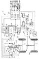
図1は、本発明の一実施例としての動力出力装置を搭載するハイブリッド自動車20の構成の概略を示す構成図である。実施例のハイブリッド自動車20は、4輪駆動により走行可能な自動車であり、エンジン22からの動力をトルクコンバータ25や無段変速機としてのCVT50,ギヤ機構65を介して前軸64に出力して前輪63a,63bを駆動する前輪駆動系と、モータ40からの動力をギヤ機構68を介して後軸67に出力して後輪66a,66bを駆動する後輪駆動系と、装置全体をコントロールするハイブリッド用電子制御ユニット70とを備える。トルクコンバータ25とCVT50との間にはクラッチC1が設けられており、エンジン22をCVT50側から切り離すことができるようになっている。ハイブリッド自動車20は、この他に、エンジン22からの動力を用いてCVT50やクラッチC1を駆動するためのライン油圧を発生させる機械式オイルポンプ26や低圧バッテリから電力により駆動する電動オイルポンプ36を備える。
FIG. 1 is a configuration diagram showing an outline of a configuration of a
エンジン22は、ガソリンまたは軽油などの炭化水素系の燃料により動力を出力する内燃機関であり、エンジン22のクランクシャフト23には、スタータモータ22aが取り付けられていると共にオルタネータ32や機械式オイルポンプ26がベルト24により取り付けられている。エンジン22の運転制御、例えば燃料噴射制御や点火制御,吸入空気量調節制御などは、エンジン用電子制御ユニット(以下、エンジンECUという)29により行なわれる。エンジンECU29は、ハイブリッド用電子制御ユニット70と通信しており、ハイブリッド用電子制御ユニット70からの制御信号によりエンジン22を運転制御すると共に必要に応じてクランクシャフト23に取り付けられエンジン22の回転数を検出する回転数センサ23aからの回転数Neなどエンジン22の運転状態に関するデータをハイブリッド用電子制御ユニット70に出力する。
The
モータ40は、発電機として駆動することができると共に電動機として駆動できる周知の同期発電電動機として構成されており、インバータ41を介して高圧バッテリ31と電力をやり取りしたりオルタネータ32から電力の供給を受ける。モータ40は、モータ用電子制御ユニット(以下、モータECUという)42により駆動制御されている。モータECU42には、モータ40を駆動制御するために必要な信号、例えばモータ40の回転子の回転位置を検出する回転位置検出センサ43からの信号や図示しない電流センサにより検出されるモータ40に印加される相電流などが入力されている。モータECU42は、ハイブリッド用電子制御ユニット70と通信しており、ハイブリッド用電子制御ユニット70からの制御信号によってインバータ41へのスイッチング制御信号を出力することによりモータ40を駆動制御すると共に必要に応じてモータ40の運転状態に関するデータをハイブリッド用電子制御ユニット70に出力する。
The
高圧バッテリ31は、定格電圧Vh(例えば42[V])の二次電池として構成されており、オルタネータ32から供給された電力を蓄電すると共にモータ40と電力をやり取りする。低圧バッテリ35は、定格電圧Vhよりも低い定格電圧Vl(例えば12[V]程度)の二次電池として構成されており、オルタネータ32からDC/DCコンバータ34を介して供給された電力を蓄電すると共に図示しない補機などの低電圧で作動する機器に電力を供給する。高圧バッテリ31や低圧バッテリ35,DC/DCコンバータ34は、バッテリ用電子制御ユニット(以下、バッテリECUという)30によって管理されている。バッテリECU30には、高圧バッテリ31や低圧バッテリ35を管理するのに必要な信号、例えば、図示しないセンサによって検出された両バッテリの端子間電圧や,充放電電流,電池温度などが入力されており、必要に応じて両バッテリの状態に関するデータを通信によりハイブリッド用電子制御ユニット70に出力する。なお、バッテリECU30では、高圧バッテリ31や低圧バッテリ35を管理するために充放電電流の積算値に基づいて残容量(SOC)も演算している。
The
CVT50は、溝幅が変更可能でインプットシャフト51に接続されたプライマリープーリー53と、同じく溝幅が変更可能で駆動軸としてのアウトプットシャフト52に接続されたセカンダリープーリー54と、プライマリープーリー53およびセカンダリープーリー54の溝に架けられたベルト55と、プライマリープーリー53およびセカンダリープーリー54の溝幅を変更する第1アクチュエータ56および第2アクチュエータ57とを備え、第1アクチュエータ56および第2アクチュエータ57を用いてプライマリープーリー53およびセカンダリープーリー54の溝幅を変更することによりインプットシャフト51の動力を無段階に変速してアウトプットシャフト52に出力する。ここで、第1アクチュエータ56は変速比の制御に用いられ、第2アクチュエータ57はCVT50の伝達トルク容量を調節するためのベルト55の狭圧力の制御に用いられる油圧式のアクチュエータとして構成されている。
The
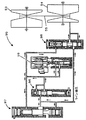
図2は第1アクチュエータ56としての変速制御機構90の構成の概略を示す構成図であり、図3は第2アクチュエータ57としてのベルト狭圧力制御機構95の構成の概略を示す構成図である。変速制御機構90は、図2に示すように、デューティソレノイド91,92と、変速用コントロールバルブ93,94とにより構成されており、デューティソレノイド91のデューティ比を制御して変速用コントロールバルブ93を開方向に調節すると共に変速用コントロールバルブ94を閉方向に調節することにより機械式オイルポンプ26または電動オイルポンプ36からのライン油圧をプライマリープーリー53に作用させてCVT50をアップシフトし、デューティソレノイド92のデューティ比を制御して変速用コントロールバルブ93を閉方向に調節すると共に変速用コントロールバルブ94を開方向に調節することによりプライマリープーリー53に作用しているライン油圧を抜いてCVT50をダウンシフトすることができるようになっている。ベルト狭圧力制御機構95は、図3に示すように、コントロールバルブ96と、レギュレータ97と、コントロールバルブ98と、リニアソレノイド99とにより構成されており、リニアソレノイド99を制御してコントロールバルブ96から入力された油圧をレギュレータ97とコントロールバルブ98とに供給してその開閉を調節することによりライン油圧を調節すると共にセカンダリープーリー54に供給する油圧を調節してベルト55の狭圧力を調節できるようになっている。
FIG. 2 is a configuration diagram showing an outline of the configuration of the speed
CVT50の変速制御やベルト狭圧力制御は、CVT用電子制御ユニット(以下、CVTECUという)59により行なわれる。このCVTECU59には、インプットシャフト51に取り付けられた回転数センサ61からのインプットシャフト51の回転数Ninやアウトプットシャフト52に取り付けられた回転数センサ62からのアウトプットシャフト52の回転数Nout,トルクコンバータ25に取り付けられた回転数センサ25aからのタービン回転数Ntなどが入力されており、CVTECU59からは第1アクチュエータ56(デューティソレノイド91,92)および第2アクチュエータ57(リニアソレノイド99)および電動オイルポンプ36の図示しない電気モータへの駆動信号が出力されている。また、CVTECU59は、ハイブリッド用電子制御ユニット70と通信しており、ハイブリッド用電子制御ユニット70からの制御信号によってCVT50の変速比を制御すると共に必要に応じてインプットシャフト51の回転数Ninやアウトプットシャフト52の回転数NoutなどCVT50の運転状態に関するデータをハイブリッド用電子制御ユニット70に出力する。
Shift control and belt narrow pressure control of the
このCVTECU50は、クラッチC1の接続の制御も行っている。図4にクラッチC1のアクチュエータとしての油圧回路100の構成の一例を示す。油圧回路100は、デューティソレノイド102,104と、シフトコントロールバルブ106とにより構成されている。シフトコントロールバルブ106は、ライン油圧が生じているときにはデューティソレノイ104からの油圧によりライン油圧とクラッチC1とのラインを閉じ、デューティソレノイド102によるデューティ比を制御することによってクラッチC1への油圧を調節し、ライン油圧が生じていないときにはライン油圧を直接クラッチC1に供給する。したがって、ライン油圧が生じていないときに電動オイルポンプ36を駆動すると、電動オイルポンプ36からの作動オイルが直接クラッチC1に供給される。
The
ハイブリッド用電子制御ユニット70は、CPU72を中心とするマイクロプロセッサとして構成されており、CPU72の他に処理プログラムを記憶するROM74と、データを一時的に記憶するRAM76と、図示しない入出力ポートおよび通信ポートとを備える。ハイブリッド用電子制御ユニット70には、イグニッションスイッチ80からのイグニッション信号や,シフトレバー81の操作位置を検出するシフトポジションセンサ82からのシフトポジションSP,アクセルペダル83の踏み込み量を検出するアクセルペダルポジションセンサ84からのアクセル開度Acc,ブレーキペダル85の踏み込み量を検出するブレーキペダルポジションセンサ86からのブレーキペダルポジションBP,車速センサ88からの車速V,加速度センサ89からの加速度αなどが入力ポートを介して入力されている。ハイブリッド用電子制御ユニット70からは、オルタネータ32への制御信号や電動オイルポンプ36の図示しない電動モータへの駆動信号などが出力ポートを介して出力されている。また、ハイブリッド用電子制御ユニット70は、エンジンECU29やバッテリECU30,モータECU42,CVTECU59と各種制御信号やデータのやり取りを行なっている。
The hybrid
こうして構成された実施例のハイブリッド自動車20は、運転者のアクセル操作に応じて、主としてエンジン22からの動力を前輪に出力して走行し、必要に応じてモータ40からの動力を後輪に出力して4輪駆動により走行する。4輪駆動により走行する場合の例としては、例えばアクセルペダル83が大きく踏み込まれた急加速時や車輪がスリップしたときなどがあげられる。また、走行中にブレーキペダル85が踏み込まれたときなどの減速時には、クラッチC1の接続を解除しエンジン22をCVT50から切り離した状態でエンジン22を停止すると共にモータ40を回生制御して後輪66a,66bに制動力を付与すると共にその運動エネルギを電力に変換して高圧バッテリ31に回収する。
The
次に、こうして構成された実施例のハイブリッド自動車20の動作、特に、クラッチC1の接続が解除され且つエンジン22の運転が停止された状態でエンジン22を始動すると共にクラッチC1を接続する際の動作(以下、「始動接続時動作」という)について説明する。この始動接続時動作は、例えば、減速時にはクラッチC1の接続を解除してエンジン22をCVT50から切り離して停止し、この状態でモータ40を回生制御して制動力を付与すると共に運動エネルギを回収している最中に運転者がアクセルペダル83を踏み込んだときや、こうした制動により車両が停止直前の状態となり次に発進する準備が必要と判断されたときに行なわれる。実施例では、始動接続時動作はハイブリッド用電子制御ユニット70により実行される図5に例示する始動接続時制御ルーチンにより実行される。
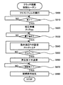
Next, the operation of the
始動接続時制御が実行されると、ハイブリッド用電子制御ユニット70のCPU72は、まず、エンジンECU29でエンジン22を始動してその回転数Neを制御するエンジン始動時制御の実行が開始されるようエンジンECU29に実行開始指示を送信すると共にCVTECU59でCVT50のインプットシャフト51の回転数Ninを変更する変速制御やクラッチC1を接続するクラッチ接続制御の実行が開始されるようCVTECU59に実行開始指示を送信する(ステップS100)。実行開始指示を受信したエンジンECU29は図6に例示するエンジン始動時制御ルーチンを実行することによりエンジン始動時制御の実行を開始し、実行開始指示を受信したCVTECU59は図7に例示する変速制御ルーチンや図8に例示するクラッチ接続制御ルーチンの実行することにより変速制御やクラッチ接続制御の実行を開始する。これらの制御については後述する。
When the start connection control is executed, the
次に、ブレーキペダルポジションセンサ86からブレーキペダルポジションBPを入力し(ステップS110)、ブレーキペダルポジションBPに基づいてブレーキオンであるか否かを判定する(ステップS120)。ブレーキオフのときにはオフセット回転数Nofstに正の回転数N1を設定し(ステップS130)、ブレーキオンのときにはオフセット回転数Nofstにマイナスの回転数N1を設定する(ステップS140)。ここで、オフセット回転数Nofstは、クラッチC1を接続する際に生じ得るトルク変動を運転者の加減速要求に応じた方向にすることにより運転者に違和感を与えないようにするためにインプットシャフト51の回転数Ninとエンジン22の回転数Neとに生じさせる回転数差であり、正の値のときにエンジン22の回転数Neがインプットシャフト51の回転数Ninより大きくなるように設定される。また、回転数N1は、比較的小さな回転数であり、例えば50rpmや100rpm程度の回転数を用いることができる。
Next, the brake pedal position BP is input from the brake pedal position sensor 86 (step S110), and it is determined whether the brake is on based on the brake pedal position BP (step S120). When the brake is off, a positive rotational speed N1 is set to the offset rotational speed Nofst (step S130), and when the brake is on, a negative rotational speed N1 is set to the offset rotational speed Nofst (step S140). Here, the offset rotation speed Nofst is set so that the torque fluctuation that may occur when the clutch C1 is connected is set in a direction according to the driver's acceleration / deceleration request so as not to give the driver a sense of incongruity. The rotational speed difference between the rotational speed Nin of the
こうしてオフセット回転数Nofstを設定すると、このルーチンで学習する時間補正値Tc2をRAM76の所定領域から入力すると共に(ステップS150)、インプットシャフト51の回転数Ninやエンジン22の回転数Neを入力し(ステップS160)、入力したインプットシャフト51の回転数Ninとエンジン22の回転数Neとの回転数差の時間微分値dnを計算すると共に(ステップS170)、次式(1)に示すように、インプットシャフト51の回転数Ninとエンジン22の回転数Neとの回転数差に設定したオフセット回転数Nofstを加えたものを計算した時間微分値dnで除してこれに入力した時間補正値Tc2を加えて判定用時間Tc0を計算し(ステップS180)、計算した判定用時間Tc0が油圧所用時間Tc1以下になるまで(ステップS190)、回転数Ninや回転数Neを入力して判定用時間Tc0を計算する処理(ステップS160〜S190)を繰り返す。ここで、インプットシャフト51の回転数Ninについては、回転数センサ61により検出されたものをCVTECU59から通信により入力するものとした。また、エンジン22の回転数Neについては、回転数センサ23aにより検出されたものをエンジンECU29から通信により入力するものとした。判定用時間Tc0は、式(1)に示すように、インプットシャフト51の回転数Ninとエンジン22の回転数Neとの回転数差がオフセット回転数Nofstに一致するまでに要する時間に時間補正値Tc2を加えたものとなる。時間補正値Tc2は、後述するが、クラッチC1の接続タイミングの経年変化などによるバラツキを補正するものである。また、油圧所用時間Tc1は、クラッチC1への油圧指示を行なってから実油圧がクラッチC1の入力軸側の回転数を一定値で保持しながらクラッチ伝達トルクの変動を許容できるクラッチ容量を持たせる油圧Pc1に至るまでに要する時間としての実験などにより求められている時間である。したがって、判定用時間Tc0が油圧所用時間Tc1以下になるのを待つ処理は、インプットシャフト51の回転数Ninとエンジン22の回転数Neとの回転数差がオフセット回転数Nofstに至るのに必要な時間が経年変化のバラツキを考慮してクラッチC1の油圧をクラッチ伝達トルクの変動を許容させるクラッチ容量となる油圧Pc1にするのに必要な時間以下となるのを判定する処理となる。即ち、このタイミングでクラッチC1への油圧の昇圧を開始すれば、クラッチC1の実油圧が油圧Pc1に至ったときにインプットシャフト51の回転数Ninとエンジン22の回転数Neとの回転数差がオフセット回転数Nofstになるようにすることができるのである。実施例でも、判定用時間Tc0が油圧所用時間Tc1以下となると、CVTECU59にクラッチC1への油圧の昇圧を指示する(ステップS200)。なお、判定用時間Tc0が油圧所用時間Tc1に至ったタイミングで昇圧を開始する処理は、昇圧を開始するタイミングとしては、経年変化などを考慮すれば、油圧所用時間Tc1から時間補正値Tc2を減じた時間であるから、この時間を昇圧開始タイミングとして設定し、判定用時間Tc0から時間補正値Tc2を減じた時間がこの昇圧開始のタイミングに至ったときにクラッチC1の昇圧を開始するものと考えることができる。
When the offset rotational speed Nofst is thus set, the time correction value Tc2 learned in this routine is input from a predetermined area of the RAM 76 (step S150), and the rotational speed Nin of the
Tc0=(Nin-Ne+Nofst)/dn+Tc2 (1) Tc0 = (Nin-Ne + Nofst) / dn + Tc2 (1)
こうして昇圧指示すると、インプットシャフト51の回転数Ninとエンジン22の回転数Neと加速度αとを入力すると共に(ステップS210)、入力した加速度αから前回のステップS210を実行したときに入力した加速度α(図中、前回α)を減じて加速度変化量Δαを計算し(ステップS220)、計算した加速度変化量Δαを打ち消す方向にエンジン22からの出力トルクが変化するようエンジン22の点火時期を進角または遅角させ(ステップS230〜S250)、入力したインプットシャフト51の回転数Ninとエンジン22の回転数Neとの回転数差が所定時間(例えば0.5秒など)に亘って継続してクラッチC1の接続を判定するための閾値Nset未満となるまで(ステップS260,S270)、加速度αを演算すると共に加速度変化量Δαを打ち消す方向へのエンジン22の点火時期を変更する処理(ステップS210〜S270)を繰り返す。エンジン22は、後述するエンジン始動時制御で説明するように、最もトルクを発生させることができる点火タイミングより点火時期を遅角させてエンジン22を始動するから、点火時期を進角させればエンジン22からの出力トルクを大きくすることができ、点火時期を遅角させればエンジン22からの出力トルクを小さくすることができる。実施例では、加速度変化量Δαが正の値の閾値αrefより大きいときには車両は加速しているから、エンジン22からの出力トルクを小さくするために点火時期を遅角させ(ステップS250)、加速度変化量Δαが負の値の閾値−αrefより小さいときには車両は減速しているから、エンジン22からの出力トルクを大きくするために点火時期を進角させるのである(ステップS240)。この場合の遅角量や進角量は、この繰り返し処理の繰り返し頻度に応じて設定することができるし、加速度変化量Δαの大きさにゲインを乗じて設定することもできる。なお、閾値αrefは加減速を判定する程度のものであるから、値0近傍の値を用いることができる。また、加速度変化量Δαが閾値−αref以上で閾値αref未満のときにはエンジン22の出力トルクは変更しない。
When the pressure is instructed in this way, the rotational speed Nin of the
入力したインプットシャフト51の回転数Ninとエンジン22の回転数Neとの回転数差がクラッチC1の接続を判定する閾値Nset未満となって所定時間経過すると、エンジン22の点火時期の進角や遅角が行なわれたときには時間補正値Tc2を増減してRAM76の所定領域に書き込むことにより更新し(ステップS280〜S300)、クラッチC1の接続完了をエンジンECU29やCVTECU59に送信して(ステップS310)、始動接続時制御ルーチンを終了する。実施例では、エンジン22の点火時期の進角が行なわれたときには時間補正値Tc2を微小時間ΔTだけ減少する更新を行なうことにより、クラッチC1への油圧の昇圧タイミングを早めてクラッチC1を接続する際に生じ得る車両の減速度を抑制し、エンジン22の点火時期の遅角が行なわれたときには時間補正値Tc2を微小時間ΔTだけ増加する更新を行なうことにより、クラッチC1への油圧の昇圧タイミングを遅くしてクラッチC1を接続する際に生じ得る車両の加速度を抑制するものとした。このように、時間補正値Tc2を更新することにより、次回の始動接続時動作のクラッチC1の接続の際に生じ得る車両の加速度変化を抑制することができる。
When a predetermined time elapses when the difference in rotational speed between the input rotational speed Nin of the
ハイブリッド用電子制御ユニット70からの指示に基づいてエンジンECU29により図6に例示するエンジン始動制御ルーチンが実行されると、エンジンECU29は、まず、スタータモータ22aによるクランキングを開始すると共に(ステップS400)、エンジン22の点火時期を最もトルクを発生させることができる点火タイミングより所定角度だけ遅角させて(ステップS410)、燃料噴射制御や点火制御を開始し(ステップS420)、完爆するのを確認する(ステップS430)。ここで、点火タイミングを遅角させる所定角度は、エンジン22を始動することができると共に更に点火時期を遅角させることによりエンジン22からの出力トルクを低下させることができる程度の角度として設定されている。
When an engine start control routine illustrated in FIG. 6 is executed by the
完爆を確認すると、インプットシャフト51の回転数Ninと回転数センサ23aからのエンジン22の回転数Neとを入力し(ステップS440)、インプットシャフト51の回転数Ninとエンジン22の回転数Neとの回転数差がオフセット回転数Nofstとなるようスロットル開度THを設定し(ステップS450)、設定したスロットル開度となるよう図示しないスロットルモータを駆動制御し、クラッチC1への油圧の昇圧が指示されるまで(ステップS460)、こうした入力処理とスロットル開度THとの設定処理を繰り返す。ここで、インプットシャフト51の回転数Ninについては、回転数センサ61により検出されたものを通信により入力するものとした。こうした処理により、インプットシャフト51の回転数Ninとエンジン22の回転数Neとの回転数差がオフセット回転数Nofstに至るようになる。クラッチC1への油圧の昇圧が指示されると、そのときのスロットル開度THを保持した状態でクラッチC1の接続完了を待って(ステップS470)、このルーチンを終了する。ここで、クラッチC1への油圧の昇圧が指示されたときのスロットル開度THを保持するのは、インプットシャフト51の回転数Ninとエンジン22の回転数Neとの回転数差がオフセット回転数Nofstとなるようスロットル開度THを設定する処理を継続すると、クラッチC1の接続により回転数差がオフセット回転数Nofstより小さくなることに基づいて回転数差をオフセット回転数Nofstに維持するためにスロットル開度THを大きくするのを回避するためである。こうした処理により、インプットシャフト51の回転数Ninとエンジン22の回転数Neとの回転数差をオフセット回転数Nofstとした状態でクラッチC1の接続を行なうことができる。
When the complete explosion is confirmed, the rotational speed Nin of the
ハイブリッド用電子制御ユニット70からの指示に基づいてCVTECU59により図7に例示する変速制御ルーチンが実行されると、CVTECU59は、まず、エンジン22の回転数Neを入力すると共に(ステップS500)、エンジン22の回転数NeがCVT50の変速比の変更が可能な回転数である閾値Nref以上であるか否かを判定し(ステップS510)、エンジン22の回転数Neが閾値Nref未満のときにはクラッチC1の接続が完了したか否かを判定する(ステップS540)。ここで、エンジン22の回転数Neは、回転数センサ23aにより検出されたものを通信により入力するものとした。エンジン22の回転数Neが閾値Nref未満の状態を維持すると共にクラッチC1の接続が完了していないときには、こうした入力処理と判定処理を繰り返す。クラッチC1の接続は、インプットシャフト51の回転数NinによってはCVT50の変速比の変更なしに行なわれることもあるからである。この場合、何もせずに本ルーチンを終了する。一方、エンジン22の回転数Neが閾値Nref以上に至ると、クラッチC1による接続が完了するまで回転数センサ61からのインプットシャフト51の回転数Ninを入力すると共に入力した回転数Ninが同期回転数Ntagに一致する変速比となるよう油圧制御する処理を繰り返し(ステップS520,S530)、クラッチC1による接続が完了すると、本ルーチンを終了する。CVT50の変速比を変更する処理は、通常はインプットシャフト51の回転数Ninは閾値Nrefより大きいことが多いから、アップシフトすることにより行なわれる。この場合、変速制御機構90では、デューティソレノイド91のデューティ比を制御して変速用コントロールバルブ93を開方向に調節すると共に変速用コントロールバルブ94を閉方向に調節することにより機械式オイルポンプ26または電動オイルポンプ36からのライン油圧をプライマリープーリー53に作用させてCVT50をアップシフトする。なお、ダウンシフトするときは、デューティソレノイド92のデューティ比を制御して変速用コントロールバルブ93を閉方向に調節すると共に変速用コントロール94を開方向に調節することによりプライマリープーリー53に作用しているライン油圧を抜くことにより行なう。このようにインプットシャフト51の回転数Ninを変更する制御は油圧制御により行なわれるから、モータの制御のように迅速には行なうことはできない。
When the shift control routine illustrated in FIG. 7 is executed by the
ハイブリッド用電子制御ユニット70からの指示に基づいてCVTECU59により図8に例示するクラッチ接続制御ルーチンが実行されると、CVTECU59は、まず、高めの油圧としてクラッチC1のシリンダに作動オイルを詰め込むファストフィルを実行する(ステップS600)。ファストフィルは、エンジン22の回転数Neが閾値Nrefに至るまでは電動オイルポンプ36からの油圧を直接クラッチC1に供給することによって行ない、エンジン22の回転数Neが閾値Nrefに至った以降は機械式オイルポンプ26からの油圧をデューティソレノイド102のデューティ比を制御することにより行なう。次に、ファストフィルの完了を判定すると(ステップS610)、クラッチC1に係合力を発生させない油圧Plowを指示油圧Piに設定してハイブリッド用電子制御ユニット70からの昇圧指示(図5のルーチンのステップS200)を受信するまで低圧待機する(ステップS620,S630)。ハイブリッド用電子制御ユニット70からの昇圧指示を受信すると、指示油圧Piがクラッチ伝達トルクの変動を許容できるクラッチ容量を持たせる油圧Pc1に至るまで指示油圧Piを徐々に上昇させるために指示油圧Piに微小油圧ΔPを加えた値に指示油圧Piを更新する処理を繰り返し(ステップS640,S650)、指示油圧Piが油圧Pc1に至ったときに昇圧完了をハイブリッド用電子制御ユニット70に送信する(ステップS660)。ここで、微小油圧ΔPは、繰り返し処理の繰り返し頻度に応じて定めることができる。そして、ハイブリッド用電子制御ユニット70からのクラッチC1の接続完了を受信するまで待って(ステップS670)、指示油圧PiをクラッチC1の接続時の保持油圧(例えば最大油圧)にして(ステップS680)、本ルーチンを終了する。
When the clutch connection control routine illustrated in FIG. 8 is executed by the
図9は、上述した始動接続時動作の際のインプットシャフト51の回転数Ninやエンジン22の回転数Ne,クラッチC1への油圧の指示油圧Pi,車両の加速度α,アクセル開度Accの時間変化の一例を示す説明図である。この例では、時間T1に始動接続時動作の指示がなされたことによりハイブリッド用電子制御ユニット70により始動接続時制御が実行され、これに伴ってエンジンECU29によりエンジン22の始動時制御が実行されると共にCVTECU59によりCVT50の変速制御とクラッチC1の接続制御とが実行される。電動オイルポンプ36の駆動により時間T2にクラッチC1へのファストフィルが開始され、このファストフィルが完了した時間T3から油圧Plowによる低圧待機が実行される。エンジン22が始動し、その回転数Neが閾値Nrefに至った時間T4にCVT50の変速比の変更が開始され、判定用時間Tc0が油圧所用時間Tc1以下に至った時間T5に昇圧指示がなされ、クラッチC1への油圧の昇圧が開始される。クラッチC1への油圧が油圧Pc1に至った時間T6近傍やそれ以降に加速度αの加速度変化量Δαが閾値−αrefを下回ったり閾値αrefを上回ると、エンジン22の点火時期の進角や遅角が行なわれて、加速度αの変動が抑制される。なお、このときのインプットシャフト51の回転数Ninとエンジン22の回転数Neとの回転数差はオフセット回転数Nofstとなるようにエンジン22が制御されているから、加速度αの若干の変化が生じても運転者の予期しない方向の変化ではないため、運転者に違和感を与えない。そして、インプットシャフト51の回転数Ninとエンジン22の回転数Neとの回転数差が接続を判定する閾値Nset未満で所定時間経過した時間T7にクラッチC1の接続を完了する。
FIG. 9 shows changes over time in the rotational speed Nin of the
以上説明した実施例のハイブリッド自動車20によれば、始動接続時動作が指示されたときには、インプットシャフト51の回転数Ninとエンジン22の回転数Neとの回転数差と学習した時間補正値Tc2とに基づいて計算される判定用時間Tc0が油圧所用時間Tc1以下に至ったときにクラッチC1への油圧の昇圧を開始するから、より適正なタイミングでクラッチC1を接続することができる。この結果、クラッチC1を接続する際に生じ得る車両の加速度の変化に伴うショックを抑制することができると共に無駄なエネルギの消費を抑制することができ、車両全体のエネルギ効率を向上させることができる。しかも、クラッチC1を接続する際に生じ得る車両の加速度の変化に基づいて時間補正値Tc2を更新する学習を行なうから、経年変化やバラツキなどによるクラッチC1の接続タイミングが異なるものとなっても、より適正なタイミングでクラッチC1を接続することができる。また、クラッチC1を接続する際に生じ得る車両の加速度に変化が生じたときにはこの変化を打ち消す方向のトルクがエンジン22から出力されるようエンジン22の点火時期を進角または遅角させるから、クラッチC1を接続する際に生じ得る車両の加速度の変化を抑制することができる。
According to the
実施例のハイブリッド自動車20によれば、始動接続時動作が指示されたときには、クラッチC1を接続する際のインプットシャフト51の回転数Ninとエンジン22の回転数Neとの回転数差が運転者の加減速要求に応じたオフセット回転数Nofstとなるよう制御してクラッチC1を接続するから、クラッチC1を接続する際に生じ得る車両の加減速を運転者の意図する方向とすることができ、運転者に違和感を生じさせるのを抑制することができる。
According to the
実施例のハイブリッド自動車20では、始動接続時動作が指示されたときには、ブレーキペダルポジションBPによるブレーキオンやブレーキオフによりクラッチC1を接続する際のインプットシャフト51の回転数Ninとエンジン22の回転数Neとの回転数差としてのオフセット回転数Nofstを設定するものとしたが、運転者の加減速要求に応じたオフセット回転数Nofstとすればよいから、アクセル開度Accによるアクセルオンやアクセルオフ,アクセル開度Accや車速Vに基づく車両要求駆動力の増減などによりオフセット回転数Nofstを設定するものとしてもよい。また、こうしたオフセット回転数Nofstは、予め設定された回転数N1を用いる必要はなく、駆動力や制動力の大きさに応じて設定するものとしてもよい。また、運転者の加減速要求に基づくオフセット回転数Nofstを設定しないもの、即ち、クラッチC1を接続する際のインプットシャフト51の回転数Ninとエンジン22の回転数Neとの回転数差として値0とするものとしてもよい。
In the
実施例のハイブリッド自動車20では、クラッチC1を接続する際に生じ得る車両の加速度に変化が生じたときにはこの変化を打ち消す方向のトルクがエンジン22から出力されるようエンジン22の点火時期を進角または遅角させるものとしたが、車両の加速度の変化を打ち消す方向のトルクをモータ40から出力するものとしても構わない。この場合、エンジン22の点火時期の進角や遅角も並行して行なうものとしてもよい。また、こうした車両の加速度の変化を抑制する制御を行なわないものとしても構わない。
In the
実施例のハイブリッド自動車20では、クラッチC1を接続する際に生じ得る車両の加速度の変化に基づいて時間補正値Tc2を更新する学習を行なうものとしたが、こうした時間補正値Tc2の学習は行なわないものとしても構わない。また、クラッチC1に供給される油圧の作動オイルの温度や外気の温度を検出し、この作動オイルの温度や外気の温度に基づいて時間補正値Tc2を補正するものとしても構わない。この場合、作動オイルの温度や外気の温度が高いほどオイルの粘性が低くなってクラッチC1への油圧の昇圧時間は短くなるから、時間補正値Tc2が大きくなるように補正すればよい。
In the
実施例のハイブリッド自動車20では、クラッチC1の接続に関する制御をインプットシャフト51の回転数Ninとエンジン22の回転数Neとに基づいて行なうものとしたが、クラッチC1の両側に回転数センサを取り付け、この回転数センサにより検出されるクラッチC1のエンジン22側の回転数(エンジン側回転数)とクラッチC1のCVT50側の回転数(CVT側回転数)とに基づいて行なうものとしてもよい。
In the
実施例のハイブリッド自動車20では、始動接続時動作が指示されたときには、インプットシャフト51の回転数Ninとエンジン22の回転数Neとの回転数差がオフセット回転数Nofstとなるようスロットル開度THを設定してエンジン22を制御するものとしたが、アクセル開度Accと車速VとからクラッチC1を接続させる際の同期回転数Ntagを設定し、インプットシャフト51の回転数Ninが同期回転数NtagとなるようCVT50の変速比を変更する制御を行なうと共にエンジン22の回転数Neが同期回転数Ntagからオフセット回転数Nofstだけズレた回転数となるようにスロットル開度THを設定してエンジン22を制御するものとしても構わない。
In the
実施例のハイブリッド自動車20では、トルクコンバータ25とCVT50との間にクラッチC1を設けるものとしたが、トルクコンバータ25とエンジン22との間にクラッチを設けるものとしてもよい。
In the
実施例のハイブリッド自動車20では、モータ40の動力を後軸67に出力するものとしたが、モータ40の動力を前軸64に出力するものとしてもよいし、モータ40を備えないものとしても差し支えない。また、モータ40を搭載しないものとしても構わない。
In the
実施例のハイブリッド自動車20では、変速機としてベルト式のCVT50を用いるものとしたが、トロイダル式などの他のタイプの無段変速機を用いるものとしてもよいし、有段変速機を用いるものとしても構わない。
In the
実施例では、動力出力装置を搭載したハイブリッド自動車20として説明したが、こうした動力出力装置を自動車以外の車両や船舶,航空機などの移動体に搭載するものとしてもよいし、動力出力装置を建設設備などの移動しない設備に組み込むものとしても差し支えない。また、こうした動力出力装置やこれを搭載した車両の形態に限定されるものではなく、動力出力装置の制御方法やこうした動力出力装置を搭載する車両の制御方法の形態としてもよい。
In the embodiment, the
以上、本発明を実施するための最良の形態について実施例を用いて説明したが、本発明はこうした実施例に何等限定されるものではなく、本発明の要旨を逸脱しない範囲内において、種々なる形態で実施し得ることは勿論である。 The best mode for carrying out the present invention has been described with reference to the embodiments. However, the present invention is not limited to these embodiments, and various modifications can be made without departing from the gist of the present invention. Of course, it can be implemented in the form.
本発明は、動力出力装置や車両の製造産業などに利用可能である。 The present invention can be used in the power output apparatus and the vehicle manufacturing industry.
20 ハイブリッド自動車、22 エンジン、22a スタータモータ、23 クランクシャフト、23a 回転数センサ、24 ベルト、25 トルクコンバータ、25a 回転数センサ、26 機械式オイルポンプ、29 エンジン用電子制御ユニット(エンジンECU)、30 バッテリ用電子制御ユニット(バッテリECU)、31 高圧バッテリ、32 オルタネータ、34 DC/DCコンバータ、35 低圧バッテリ、36 電動オイルポンプ、40 モータ、41 インバータ、42 モータ用電子制御ユニット(モータECU)、43 回転位置検出センサ、50 CVT、51 インプットシャフト、52 アウトプットシャフト、53 プライマリープーリー、54 セカンダリープーリー、55 ベルト、56 第1アクチュエータ、57 第2アクチュエータ、59 CVT用電子制御ユニット(CVTECU)、61 回転数センサ、62 回転数センサ、63a,63b 前輪、64 前軸、65,68 ギヤ機構、66a,66b 後輪、67 後軸、70 ハイブリッド用電子制御ユニット、72 CPU、74 ROM、76 RAM、80 イグニッションスイッチ、81 シフトレバー、82 シフトポジションセンサ、83 アクセルペダル、84 アクセルペダルポジションセンサ、85 ブレーキペダル、86 ブレーキペダルポジションセンサ、88 車速センサ、89 加速度センサ、90 変速制御機構、91,92 デューティソレノイド、93,94 変速用コントロールバルブ、95 ベルト狭圧力制御機構、96 コントロールバルブ、97 レギュレータ、98 コントロールバルブ、99 リニアソレノイド、100 油圧回路、102,104 デューティソレノイド、106 シフトコントロールバルブ、C1 クラッチ。
DESCRIPTION OF SYMBOLS 20 Hybrid vehicle, 22 Engine, 22a Starter motor, 23 Crankshaft, 23a Rotational speed sensor, 24 Belt, 25 Torque converter, 25a Rotational speed sensor, 26 Mechanical oil pump, 29 Engine electronic control unit (engine ECU), 30 Electronic control unit for battery (battery ECU), 31 high voltage battery, 32 alternator, 34 DC / DC converter, 35 low voltage battery, 36 electric oil pump, 40 motor, 41 inverter, 42 electronic control unit for motor (motor ECU), 43 Rotation position detection sensor, 50 CVT, 51 input shaft, 52 output shaft, 53 primary pulley, 54 secondary pulley, 55 belt, 56 first actuator, 57 second actuator 59, 59 CVT electronic control unit (CVTECU), 61 rpm sensor, 62 rpm sensor, 63a, 63b front wheel, 64 front axle, 65, 68 gear mechanism, 66a, 66b rear wheel, 67 rear axle, 70 hybrid Electronic control unit, 72 CPU, 74 ROM, 76 RAM, 80 ignition switch, 81 shift lever, 82 shift position sensor, 83 accelerator pedal, 84 accelerator pedal position sensor, 85 brake pedal, 86 brake pedal position sensor, 88 vehicle speed sensor , 89 Acceleration sensor, 90 Shift control mechanism, 91, 92 Duty solenoid, 93, 94 Shift control valve, 95 Belt narrow pressure control mechanism, 96 Control valve, 97 Regulator, 98 Control valve, 99 Rini Solenoids, 100 a hydraulic circuit, 102 and 104 duty solenoid, 106 shift control valve, C1 clutch.
Claims (14)
内燃機関と、
前記内燃機関の動力軸側に接続された入力軸と前記駆動軸に接続された出力軸とを有し、前記内燃機関からの動力を変速して前記出力軸側に伝達可能な変速伝達手段と、
作動流体の圧力を用いて前記内燃機関の動力軸側と前記変速伝達手段の入力軸側との接続および接続の解除を行なう接続解除手段と、
前記接続解除手段における前記内燃機関の動力軸側の回転数である動力軸側回転数を検出する動力軸側回転数検出手段と、
前記接続解除手段における前記変速伝達手段の入力軸側の回転数である入力軸側回転数を検出する入力軸側回転数検出手段と、
前記内燃機関の動力軸側と前記変速伝達手段の入力軸側との接続が解除され且つ前記内燃機関の運転が停止された状態で前記内燃機関を始動すると共に前記内燃機関の動力軸側と前記変速伝達手段の入力軸側とを接続する始動接続指示がなされたとき、前記内燃機関を始動するよう前記内燃機関を制御し、前記検出された動力軸側回転数と前記検出された入力軸側回転数とに基づいて前記動力軸側回転数と前記入力軸側回転数との回転数差が所定の回転数差に至るまでに要する時間を推定することにより前記接続解除手段における前記作動流体の供給を開始する供給開始タイミングを設定し、前記内燃機関の動力軸側の回転数と前記変速伝達手段の入力軸側の回転数とが近づくように前記内燃機関と前記変速伝達手段との少なくとも一方を制御すると共に前記設定した供給開始タイミングを用いて前記内燃機関の動力軸側と前記変速伝達手段の入力軸側とが接続されるよう前記接続解除手段を制御する始動接続時制御手段と、
を備える動力出力装置。 A power output device that outputs power to a drive shaft,
An internal combustion engine;
Shift transmission means having an input shaft connected to the power shaft side of the internal combustion engine and an output shaft connected to the drive shaft, and capable of shifting power from the internal combustion engine and transmitting the power to the output shaft side; ,
Connection release means for connecting and releasing the connection between the power shaft side of the internal combustion engine and the input shaft side of the shift transmission means using the pressure of the working fluid;
A power shaft side rotational speed detection means for detecting a power shaft side rotational speed which is a rotational speed of the internal combustion engine on the power shaft side in the connection release means;
An input shaft side rotational speed detecting means for detecting an input shaft side rotational speed which is a rotational speed on the input shaft side of the shift transmission means in the connection release means;
The internal combustion engine is started in a state where the connection between the power shaft side of the internal combustion engine and the input shaft side of the shift transmission means is released and the operation of the internal combustion engine is stopped, and the power shaft side of the internal combustion engine and the When a start connection instruction is made to connect the input shaft side of the speed change transmission means, the internal combustion engine is controlled to start the internal combustion engine, and the detected power shaft side rotational speed and the detected input shaft side are controlled. And estimating the time required for the difference in rotational speed between the power shaft side rotational speed and the input shaft side rotational speed to reach a predetermined rotational speed difference based on the rotational speed . Supply start timing for starting supply is set, and at least one of the internal combustion engine and the transmission transmission means so that the rotational speed on the power shaft side of the internal combustion engine approaches the rotational speed on the input shaft side of the transmission transmission means Control A start-engagement control means and an input shaft side of the transmission mechanism and the power shaft of the internal combustion engine to control the disconnection means to be connected with a supply starting timing the setting as well as,
A power output device comprising:
前記駆動軸の回転に対する加減速要求を設定する加減速要求設定手段を備え、
前記始動接続時制御手段は、前記設定された加減速要求に基づいて前記変速伝達手段の入力軸側の回転数と前記内燃機関の動力軸側の回転数とが近づくよう制御する手段である
動力出力装置。 The power output device according to claim 1,
Acceleration / deceleration request setting means for setting an acceleration / deceleration request for rotation of the drive shaft,
The starting connection time control means is means for controlling the rotational speed on the input shaft side of the shift transmission means to be close to the rotational speed on the power shaft side of the internal combustion engine based on the set acceleration / deceleration request. Output device.
前記駆動軸の回転挙動を検出する回転挙動検出手段と、
前記内燃機関の動力軸側と前記変速伝達手段の入力軸側とが接続される際に前記回転挙動検出手段により検出される前記駆動軸の回転挙動に基づいて前記供給開始タイミングを学習する学習手段と、
を備える動力出力装置。 The power output device according to any one of claims 1 to 4,
Rotational behavior detecting means for detecting rotational behavior of the drive shaft;
Learning means for learning the supply start timing based on the rotational behavior of the drive shaft detected by the rotational behavior detecting means when the power shaft side of the internal combustion engine and the input shaft side of the shift transmission means are connected. When,
A power output device comprising:
る際に前記駆動軸の回転を減速する挙動を検出したときには前記供給開始タイミングが早くなるよう学習する手段である請求項5記載の動力出力装置。 The learning means learns that the supply start timing is delayed when the behavior of accelerating the rotation of the drive shaft is detected when the power shaft side of the internal combustion engine is connected to the input shaft side of the shift transmission means. And means for learning that the supply start timing is advanced when a behavior of decelerating the rotation of the drive shaft is detected when the power shaft side of the internal combustion engine is connected to the input shaft side of the shift transmission means. The power output apparatus according to claim 5.
前記作動流体の温度を検出する温度検出手段と、
該検出された温度に基づいて前記供給開始タイミングを補正するタイミング補正手段と、
を備える動力出力装置。 The power output device according to any one of claims 1 to 6,
Temperature detecting means for detecting the temperature of the working fluid;
Timing correction means for correcting the supply start timing based on the detected temperature;
A power output device comprising:
前記駆動軸の回転に対する加減速に関する加減速挙動を検出する加減速挙動検出手段と、
前記内燃機関の動力軸側と前記変速伝達手段の入力軸側とが接続される際に前記加減速挙動検出手段により検出された加減速挙動に基づいて前記駆動軸に出力される駆動力を補正する駆動力補正手段と、
を備える動力出力装置。 The power output device according to any one of claims 1 to 7,
Acceleration / deceleration behavior detecting means for detecting acceleration / deceleration behavior related to acceleration / deceleration with respect to rotation of the drive shaft;
The driving force output to the drive shaft is corrected based on the acceleration / deceleration behavior detected by the acceleration / deceleration behavior detecting means when the power shaft side of the internal combustion engine and the input shaft side of the shift transmission means are connected. Driving force correcting means for
A power output device comprising:
前記車両の加速度を検出する加速度検出手段と、
前記内燃機関の動力軸側と前記変速伝達手段の入力軸側とが接続される際に前記加速度検出手段により検出された加速度に基づいて車両の駆動力が補正されるよう前記駆動源を制御する駆動力補正手段と、
を備える車両。 The vehicle according to claim 9, wherein
Acceleration detecting means for detecting acceleration of the vehicle;
The driving source is controlled so that the driving force of the vehicle is corrected based on the acceleration detected by the acceleration detecting means when the power shaft side of the internal combustion engine is connected to the input shaft side of the shift transmission means. Driving force correction means;
A vehicle comprising:
前記駆動源は、前記駆動軸が連結された車軸または該車軸とは異なる車軸に動力を出力可能な電動機を備え、
前記駆動力補正手段は、前記電動機から出力される駆動力を補正する手段である
車両。 The vehicle according to any one of claims 10 to 12,
The drive source includes an electric motor capable of outputting power to an axle connected to the drive shaft or an axle different from the axle;
The driving force correcting means is means for correcting a driving force output from the electric motor vehicle.
前記内燃機関を始動するよう前記内燃機関を制御し、
前記接続解除手段における前記内燃機関の動力軸側の回転数と前記接続解除手段における前記変速伝達手段の入力軸側の回転数とに基づいて前記内燃機関の動力軸側の回転数と前記変速伝達手段の入力軸側の回転数との回転数差が所定の回転数差に至るまでに要する時間を推定することにより前記接続解除手段における前記作動流体の供給を開始する供給開始タイミングを設定し、
前記内燃機関の動力軸側の回転数と前記変速伝達手段の入力軸側の回転数とが近づくように前記内燃機関と前記変速伝達手段との少なくとも一方を制御すると共に前記設定した供給開始タイミングを用いて前記内燃機関の動力軸側と前記変速伝達手段の入力軸側とが接続されるよう前記接続解除手段を制御する
動力出力装置の制御方法。
Shift transmission having an internal combustion engine, an input shaft connected to the power shaft side of the internal combustion engine, and an output shaft connected to the drive shaft, capable of shifting power from the internal combustion engine and transmitting the power to the output shaft side And a connection release means for connecting and releasing the connection between the power shaft side of the internal combustion engine and the input shaft side of the shift transmission means using the pressure of the working fluid. The internal combustion engine is started in a state where the connection between the power shaft side of the engine and the input shaft side of the shift transmission means is released and the operation of the internal combustion engine is stopped, and the power shaft side of the internal combustion engine and the transmission transmission means A control method of the power output device when connecting to the input shaft side of
Controlling the internal combustion engine to start the internal combustion engine;
Based on the rotational speed on the power shaft side of the internal combustion engine in the connection release means and the rotational speed on the input shaft side of the transmission transmission means in the connection release means, the rotational speed on the power shaft side of the internal combustion engine and the shift transmission. Setting a supply start timing for starting the supply of the working fluid in the disconnection means by estimating the time required for the difference in rotation speed from the rotation speed on the input shaft side of the means to reach a predetermined rotation speed difference ;
At least one of the internal combustion engine and the transmission transmission means is controlled so that the rotational speed on the power shaft side of the internal combustion engine approaches the rotational speed on the input shaft side of the transmission transmission means, and the set supply start timing is set. A method for controlling a power output device, comprising: controlling the connection release means so that a power shaft side of the internal combustion engine and an input shaft side of the shift transmission means are connected.
Priority Applications (7)
| Application Number | Priority Date | Filing Date | Title |
|---|---|---|---|
| JP2005161616A JP4265572B2 (en) | 2005-06-01 | 2005-06-01 | POWER OUTPUT DEVICE, VEHICLE MOUNTING THE SAME, AND METHOD FOR CONTROLLING POWER OUTPUT DEVICE |
| EP06747206A EP1885573B1 (en) | 2005-06-01 | 2006-05-31 | Power output apparatus, motor vehicle equipped with power output apparatus, and control method of power output apparatus |
| PCT/JP2006/311370 WO2006129866A1 (en) | 2005-06-01 | 2006-05-31 | Power output apparatus, motor vehicle equipped with power output apparatus, and control method of power output apparatus |
| DE602006002822T DE602006002822D1 (en) | 2005-06-01 | 2006-05-31 | POWER OUTPUT DEVICE, MOTOR VEHICLE WITH THE POWER OUTPUT DEVICE AND CONTROL PROCEDURE FOR THE POWER OUTPUT DEVICE |
| CN2006800195643A CN101189152B (en) | 2005-06-01 | 2006-05-31 | Power output apparatus, motor vehicle equipped with power output apparatus, and control method of power output apparatus |
| US11/632,714 US7552793B2 (en) | 2005-06-01 | 2006-05-31 | Power output apparatus, motor vehicle equipped with power output apparatus, and control method of power output apparatus |
| KR1020077015816A KR100868960B1 (en) | 2005-06-01 | 2006-05-31 | Power output apparatus, motor vehicle equipped with power output apparatus, and control method of power output apparatus |
Applications Claiming Priority (1)
| Application Number | Priority Date | Filing Date | Title |
|---|---|---|---|
| JP2005161616A JP4265572B2 (en) | 2005-06-01 | 2005-06-01 | POWER OUTPUT DEVICE, VEHICLE MOUNTING THE SAME, AND METHOD FOR CONTROLLING POWER OUTPUT DEVICE |
Publications (2)
| Publication Number | Publication Date |
|---|---|
| JP2006335197A JP2006335197A (en) | 2006-12-14 |
| JP4265572B2 true JP4265572B2 (en) | 2009-05-20 |
Family
ID=36942229
Family Applications (1)
| Application Number | Title | Priority Date | Filing Date |
|---|---|---|---|
| JP2005161616A Active JP4265572B2 (en) | 2005-06-01 | 2005-06-01 | POWER OUTPUT DEVICE, VEHICLE MOUNTING THE SAME, AND METHOD FOR CONTROLLING POWER OUTPUT DEVICE |
Country Status (7)
| Country | Link |
|---|---|
| US (1) | US7552793B2 (en) |
| EP (1) | EP1885573B1 (en) |
| JP (1) | JP4265572B2 (en) |
| KR (1) | KR100868960B1 (en) |
| CN (1) | CN101189152B (en) |
| DE (1) | DE602006002822D1 (en) |
| WO (1) | WO2006129866A1 (en) |
Families Citing this family (34)
| Publication number | Priority date | Publication date | Assignee | Title |
|---|---|---|---|---|
| DE102006003711A1 (en) * | 2006-01-26 | 2007-08-02 | Zf Friedrichshafen Ag | Method for control of vehicle with internal combustion engine and electric drive, comprises proportional reduction of torque at both drives |
| KR100836365B1 (en) * | 2006-10-19 | 2008-06-09 | 현대자동차주식회사 | Engine start method of vehicle having starter motor and ISG |
| US8041492B2 (en) * | 2006-10-31 | 2011-10-18 | Clark Equipment Company | Engine load management for power machines |
| JP2008125318A (en) * | 2006-11-15 | 2008-05-29 | Toyota Motor Corp | Vehicle, drive device and control method therefor |
| JP5019870B2 (en) * | 2006-12-27 | 2012-09-05 | ボッシュ株式会社 | Control method of hybrid vehicle |
| NL1034876C2 (en) * | 2007-12-28 | 2009-06-30 | Bosch Gmbh Robert | Automatic transmission provided with a hydraulically powered clutch and method for its operation. |
| DE102008004366A1 (en) * | 2008-01-15 | 2009-07-16 | Robert Bosch Gmbh | Drive train arrangement of a vehicle and method for controlling the operation of a drive train arrangement of a vehicle |
| US8482181B2 (en) | 2008-06-04 | 2013-07-09 | Convergent Power, Inc. | Three phase synchronous reluctance motor with constant air gap and recovery of inductive field energy |
| US8296038B2 (en) * | 2009-03-03 | 2012-10-23 | GM Global Technology Operations LLC | Method and system for determining engine brake torque in real time |
| US8070648B2 (en) * | 2009-05-28 | 2011-12-06 | Ford Global Technologies, Llc | Transmission clutch stroking control during an engine restart in a hybrid electric vehicle |
| JP2011073483A (en) * | 2009-09-29 | 2011-04-14 | Aisin Seiki Co Ltd | Power transmission device and controller for power transmission device |
| JP5018971B2 (en) | 2010-01-29 | 2012-09-05 | トヨタ自動車株式会社 | Power transmission device |
| JP2011218836A (en) * | 2010-04-02 | 2011-11-04 | Toyota Motor Corp | Vehicular hybrid drive system |
| JP5455790B2 (en) * | 2010-05-28 | 2014-03-26 | ダイハツ工業株式会社 | Starting clutch control device |
| US9181917B2 (en) | 2010-12-27 | 2015-11-10 | Yamaha Hatsudoki Kabushiki Kaisha | Start control system and vehicle |
| WO2012095970A1 (en) * | 2011-01-12 | 2012-07-19 | トヨタ自動車株式会社 | Hybrid vehicle control apparatus |
| US9487213B2 (en) * | 2011-02-01 | 2016-11-08 | Toyota Jidosha Kabushiki Kaisha | Vehicle control device |
| JP5520250B2 (en) * | 2011-04-05 | 2014-06-11 | 富士重工業株式会社 | Hybrid vehicle control system |
| JP5899666B2 (en) * | 2011-06-07 | 2016-04-06 | 日産自動車株式会社 | Engine start control device for hybrid vehicle |
| JP2013129273A (en) * | 2011-12-21 | 2013-07-04 | Aisin Seiki Co Ltd | Drive control device for hybrid vehicle |
| WO2014070212A1 (en) * | 2012-11-05 | 2014-05-08 | Convergent Power, Inc. | Controller for toroidal motor having back emf reduction |
| KR101786653B1 (en) * | 2012-11-08 | 2017-11-15 | 현대자동차주식회사 | Method and system for learning operation of engine clutch for hybrid electric vehicle |
| CN103851109B (en) * | 2012-12-05 | 2016-05-18 | 上海汽车集团股份有限公司 | Hybrid vehicle electricity drives speed change box clutch moment kiss point location control method |
| US9592823B2 (en) * | 2012-12-17 | 2017-03-14 | Toyota Jidosha Kabushiki Kaisha | Control device for hybrid electric vehicle clutch engagement |
| US9695773B2 (en) * | 2013-03-14 | 2017-07-04 | Ford Global Technologies, Llc | Method and system for improving engine starting |
| JP6340768B2 (en) * | 2013-09-30 | 2018-06-13 | アイシン精機株式会社 | Hybrid vehicle drive device |
| US9771064B2 (en) | 2014-03-25 | 2017-09-26 | Ford Global Technologies, Llc | Systems and methods for improving vehicle driveline operation |
| DE102016202556A1 (en) * | 2016-02-18 | 2017-08-24 | Volkswagen Aktiengesellschaft | Method and control device for detecting during operation of a hybrid vehicle, whether combustion takes place in an internal combustion engine of the hybrid vehicle |
| DE102016217955A1 (en) * | 2016-09-20 | 2018-03-22 | Voith Patent Gmbh | Method for operating a hybrid vehicle |
| CN106285978B (en) * | 2016-10-20 | 2019-05-03 | 江门市大长江集团有限公司 | Oil-burning internal combustion engine control method and device |
| CN107061671A (en) * | 2017-03-29 | 2017-08-18 | 湖南江麓容大车辆传动股份有限公司 | A kind of buncher hydraulic system |
| CN112792139B (en) * | 2020-11-26 | 2023-07-28 | 广州城建职业学院 | Control method for preventing overload faults of double-core rod transmission motor |
| JP2022150547A (en) * | 2021-03-26 | 2022-10-07 | マツダ株式会社 | Control method and control system of hybrid vehicle |
| CN114718967A (en) * | 2022-02-25 | 2022-07-08 | 深圳绿米联创科技有限公司 | Method, device and system for correcting driving device, intelligent curtain and storage medium |
Family Cites Families (20)
| Publication number | Priority date | Publication date | Assignee | Title |
|---|---|---|---|---|
| JPS57146944A (en) * | 1981-03-04 | 1982-09-10 | Toyota Motor Corp | Speed change controller of automatic speed changer |
| JPS60104847A (en) * | 1983-11-11 | 1985-06-10 | Toyota Motor Corp | Line pressure control device of continuously variable transmission for car |
| JP2919183B2 (en) * | 1992-07-17 | 1999-07-12 | 株式会社エクォス・リサーチ | Hybrid vehicle |
| JP2973920B2 (en) * | 1995-05-24 | 1999-11-08 | トヨタ自動車株式会社 | Hybrid electric vehicle |
| JP3518406B2 (en) | 1998-05-15 | 2004-04-12 | トヨタ自動車株式会社 | Control device for restarting vehicle engine |
| JP3948148B2 (en) * | 1999-02-03 | 2007-07-25 | マツダ株式会社 | Hybrid vehicle |
| JP4123501B2 (en) * | 1999-08-09 | 2008-07-23 | マツダ株式会社 | Drive device for hybrid vehicle |
| JP4122142B2 (en) | 2001-05-18 | 2008-07-23 | 本田技研工業株式会社 | Hybrid vehicle drive control device |
| JP4529333B2 (en) * | 2001-08-31 | 2010-08-25 | アイシン・エィ・ダブリュ株式会社 | Vehicle control device |
| US6556910B2 (en) * | 2001-08-31 | 2003-04-29 | Aisin Aw Co., Ltd. | Control apparatus and method for vehicle having an idle stop function |
| JP4529335B2 (en) * | 2001-08-31 | 2010-08-25 | アイシン・エィ・ダブリュ株式会社 | Vehicle control device |
| JP2003212004A (en) * | 2002-01-18 | 2003-07-30 | Toyota Motor Corp | Clutch control device for hybrid vehicle |
| JP3700660B2 (en) * | 2002-03-04 | 2005-09-28 | トヨタ自動車株式会社 | Power output apparatus and automobile equipped with the same |
| JP3922549B2 (en) * | 2002-07-10 | 2007-05-30 | スズキ株式会社 | Vehicle control device |
| US6730000B1 (en) * | 2002-12-09 | 2004-05-04 | Daimlerchrysler Corporation | Interactive process during engine idle stop mode |
| JP3991882B2 (en) * | 2003-02-17 | 2007-10-17 | トヨタ自動車株式会社 | POWER OUTPUT DEVICE, ITS CONTROL METHOD, AND VEHICLE |
| US6836718B2 (en) * | 2003-04-07 | 2004-12-28 | International Truck Intellectual Property Company, Llc | Vehicle with engine idle-management system |
| JP3885766B2 (en) | 2003-05-19 | 2007-02-28 | トヨタ自動車株式会社 | Coordinated control device for vehicle power source and continuously variable transmission |
| JP3963868B2 (en) * | 2003-06-23 | 2007-08-22 | トヨタ自動車株式会社 | Control device for hybrid drive |
| US6926639B2 (en) * | 2003-07-02 | 2005-08-09 | Visteon Global Technologies, Inc. | Vehicle control method |
-
2005
- 2005-06-01 JP JP2005161616A patent/JP4265572B2/en active Active
-
2006
- 2006-05-31 DE DE602006002822T patent/DE602006002822D1/en active Active
- 2006-05-31 WO PCT/JP2006/311370 patent/WO2006129866A1/en active Application Filing
- 2006-05-31 EP EP06747206A patent/EP1885573B1/en active Active
- 2006-05-31 KR KR1020077015816A patent/KR100868960B1/en active IP Right Grant
- 2006-05-31 US US11/632,714 patent/US7552793B2/en active Active
- 2006-05-31 CN CN2006800195643A patent/CN101189152B/en active Active
Also Published As
| Publication number | Publication date |
|---|---|
| CN101189152B (en) | 2011-06-29 |
| WO2006129866A1 (en) | 2006-12-07 |
| CN101189152A (en) | 2008-05-28 |
| KR100868960B1 (en) | 2008-11-17 |
| JP2006335197A (en) | 2006-12-14 |
| US20080083579A1 (en) | 2008-04-10 |
| EP1885573B1 (en) | 2008-09-17 |
| KR20070088779A (en) | 2007-08-29 |
| EP1885573A1 (en) | 2008-02-13 |
| DE602006002822D1 (en) | 2008-10-30 |
| US7552793B2 (en) | 2009-06-30 |
Similar Documents
| Publication | Publication Date | Title |
|---|---|---|
| JP4265572B2 (en) | POWER OUTPUT DEVICE, VEHICLE MOUNTING THE SAME, AND METHOD FOR CONTROLLING POWER OUTPUT DEVICE | |
| JP4640044B2 (en) | Automobile and control method thereof | |
| US7498757B2 (en) | Control device for a hybrid electric vehicle | |
| EP1863668B1 (en) | Vehicle and control method of vehicle | |
| US7059435B2 (en) | Control apparatus for hybrid vehicle | |
| US6741917B2 (en) | Hybrid vehicle control apparatus | |
| JP4232761B2 (en) | POWER OUTPUT DEVICE, VEHICLE MOUNTING THE SAME, AND METHOD FOR CONTROLLING POWER OUTPUT DEVICE | |
| EP1493608B1 (en) | Control apparatus for hybrid vehicle | |
| JP4281740B2 (en) | Vehicle and control method thereof | |
| US9067585B2 (en) | Control device for hybrid vehicle | |
| JP2007055493A (en) | Vehicle and control method therefor | |
| WO2015092518A1 (en) | Control device for vehicle | |
| JP3454172B2 (en) | Hybrid vehicle control method | |
| JP4238846B2 (en) | VEHICLE, ITS CONTROL METHOD, AND POWER OUTPUT DEVICE | |
| JP2007284001A (en) | Vehicle and its control method | |
| JP2006182148A (en) | Automobile and its control method | |
| JP2006335196A (en) | Power output device and vehicle mounted with the same, and method for controlling the same | |
| JP2006194263A (en) | Automobile and method for controlling the same | |
| JP2006170265A (en) | Automobile and method of controlling the same | |
| JP2003065106A (en) | Power output device and electric vehicle | |
| JP2006027598A (en) | Power generation controller for vehicle and driving controller for vehicle equipped with the same | |
| JP2006189113A (en) | Automobile and method for controlling the same | |
| WO2012077188A1 (en) | Vehicle control device | |
| JP2007210551A (en) | Vehicle and its control method | |
| US11834028B2 (en) | Vehicle gear-shifting control apparatus |
Legal Events
| Date | Code | Title | Description |
|---|---|---|---|
| A621 | Written request for application examination |
Free format text: JAPANESE INTERMEDIATE CODE: A621 Effective date: 20071213 |
|
| A131 | Notification of reasons for refusal |
Free format text: JAPANESE INTERMEDIATE CODE: A131 Effective date: 20080902 |
|
| A521 | Request for written amendment filed |
Free format text: JAPANESE INTERMEDIATE CODE: A523 Effective date: 20081022 |
|
| A131 | Notification of reasons for refusal |
Free format text: JAPANESE INTERMEDIATE CODE: A131 Effective date: 20081118 |
|
| TRDD | Decision of grant or rejection written | ||
| A01 | Written decision to grant a patent or to grant a registration (utility model) |
Free format text: JAPANESE INTERMEDIATE CODE: A01 Effective date: 20090127 |
|
| A01 | Written decision to grant a patent or to grant a registration (utility model) |
Free format text: JAPANESE INTERMEDIATE CODE: A01 |
|
| A61 | First payment of annual fees (during grant procedure) |
Free format text: JAPANESE INTERMEDIATE CODE: A61 Effective date: 20090209 |
|
| R151 | Written notification of patent or utility model registration |
Ref document number: 4265572 Country of ref document: JP Free format text: JAPANESE INTERMEDIATE CODE: R151 |
|
| FPAY | Renewal fee payment (event date is renewal date of database) |
Free format text: PAYMENT UNTIL: 20120227 Year of fee payment: 3 |
|
| FPAY | Renewal fee payment (event date is renewal date of database) |
Free format text: PAYMENT UNTIL: 20120227 Year of fee payment: 3 |
|
| FPAY | Renewal fee payment (event date is renewal date of database) |
Free format text: PAYMENT UNTIL: 20130227 Year of fee payment: 4 |
|
| FPAY | Renewal fee payment (event date is renewal date of database) |
Free format text: PAYMENT UNTIL: 20130227 Year of fee payment: 4 |
|
| FPAY | Renewal fee payment (event date is renewal date of database) |
Free format text: PAYMENT UNTIL: 20140227 Year of fee payment: 5 |