JP4265357B2 - Filling system - Google Patents
Filling system Download PDFInfo
- Publication number
- JP4265357B2 JP4265357B2 JP2003340474A JP2003340474A JP4265357B2 JP 4265357 B2 JP4265357 B2 JP 4265357B2 JP 2003340474 A JP2003340474 A JP 2003340474A JP 2003340474 A JP2003340474 A JP 2003340474A JP 4265357 B2 JP4265357 B2 JP 4265357B2
- Authority
- JP
- Japan
- Prior art keywords
- liquid
- filling
- tank
- supply pipe
- liquid supply
- Prior art date
- Legal status (The legal status is an assumption and is not a legal conclusion. Google has not performed a legal analysis and makes no representation as to the accuracy of the status listed.)
- Expired - Fee Related
Links
- 239000007788 liquid Substances 0.000 claims description 187
- 238000010438 heat treatment Methods 0.000 claims description 6
- 239000007787 solid Substances 0.000 description 15
- 239000000945 filler Substances 0.000 description 8
- 235000013361 beverage Nutrition 0.000 description 5
- 238000001514 detection method Methods 0.000 description 5
- 239000000047 product Substances 0.000 description 4
- 230000001954 sterilising effect Effects 0.000 description 4
- 238000004519 manufacturing process Methods 0.000 description 3
- 238000010586 diagram Methods 0.000 description 2
- 239000002244 precipitate Substances 0.000 description 2
- 238000004659 sterilization and disinfection Methods 0.000 description 2
- 238000001816 cooling Methods 0.000 description 1
- 230000003247 decreasing effect Effects 0.000 description 1
- 238000007872 degassing Methods 0.000 description 1
- 239000003651 drinking water Substances 0.000 description 1
- 235000020188 drinking water Nutrition 0.000 description 1
- 238000000034 method Methods 0.000 description 1
- 238000002156 mixing Methods 0.000 description 1
- 230000002093 peripheral effect Effects 0.000 description 1
- 238000002360 preparation method Methods 0.000 description 1
- 230000002265 prevention Effects 0.000 description 1
- 238000003908 quality control method Methods 0.000 description 1
- 230000000630 rising effect Effects 0.000 description 1
- 238000003756 stirring Methods 0.000 description 1
- 238000003860 storage Methods 0.000 description 1
- 239000000126 substance Substances 0.000 description 1
Images

Landscapes
- Filling Of Jars Or Cans And Processes For Cleaning And Sealing Jars (AREA)
Description
本発明は、容器内に充填液を充填する充填システムに係り、特に、高温の充填液を充填するホットパック充填や、固形物入りの充填液の充填などに有効な充填システムに関するものである。 The present invention relates to a filling system that fills a container with a filling liquid, and more particularly to a filling system that is effective for hot pack filling that fills a high-temperature filling liquid, filling a filling liquid containing solids, and the like.
飲料水等の製造ラインでは、高度の品質管理が要求されており、充填される液体および容器やキャップ等を完全に殺菌しなければならない。そこで、加熱した高温の液体を容器内に充填するホットパック充填が広く行われている。ホットパック充填は、容器内に充填される液体の温度を、一定範囲の高温に維持するように温度管理を行い、この高温の液体を、充填ノズルを介して容器内に充填し、キャッピングを行った後、この容器を横倒しにすることにより高温の充填液をキャップの内面や容器の上部内面に所定時間接触させてこれらの部分の殺菌を行うようになっている。 Production lines for drinking water and the like require high quality control, and liquids to be filled and containers and caps must be completely sterilized. Therefore, hot pack filling in which a heated high-temperature liquid is filled in a container is widely performed. In hot pack filling, the temperature of the liquid filled in the container is controlled so as to maintain a high temperature within a certain range, and the high temperature liquid is filled into the container via a filling nozzle and capped. After that, the container is laid down so that the high temperature filling liquid is brought into contact with the inner surface of the cap or the upper inner surface of the container for a predetermined time to sterilize these parts.
前記のように充填される液体の温度が所定範囲の高温になるように加熱しても、ラインの停止等により充填液の流れも停止し、充填液の温度が低下して基準温度以下になってしまう場合がある。このように充填液の温度が基準より低くなると、殺菌効果が低下してしまうため、温度の低下した充填液は充填することができず、充填を再開したときにブローしなければならない。 Even if heating is performed so that the temperature of the liquid to be filled becomes a high temperature within a predetermined range as described above, the flow of the filling liquid is also stopped due to the stoppage of the line, etc. May end up. When the temperature of the filling liquid becomes lower than the standard in this way, the sterilizing effect is lowered. Therefore, the filling liquid whose temperature has been lowered cannot be filled and must be blown when filling is resumed.
一定時間以上運転が停止した場合にライン内の充填液の温度が低下してしまうと、その充填液をブローしなければならず、ロスが大きいという問題が発生するため、一定時間以上運転が停止した場合に、配管内の液を戻すことにより、ロスする液の量を少なくすることができる充填システムが提案されている(例えば、特許文献1参照)。 If the temperature of the filling liquid in the line drops when the operation is stopped for a certain time or more, the filling liquid must be blown, causing a problem that the loss is large. In such a case, a filling system has been proposed that can reduce the amount of liquid lost by returning the liquid in the pipe (see, for example, Patent Document 1).
特許文献1に記載された発明は、製品液を貯留するクッションタンクと、製品液を加熱殺菌する加熱殺菌装置と、加熱殺菌装置から送られた製品液を貯留するとともに、レベルセンサが設けられた微加圧タンクと、フィラに加圧して送液する加圧タンクと、加熱殺菌装置と微加圧タンクとの間に設けられた第1切換バルブと、第1切換バルブとクッションタンクとを接続する第1戻り通路とを備えた構成の飲料製造ラインに、さらに、加圧タンクとフィラとの間に第2切換バルブを設けるとともに、この第2切換バルブと前記クッションタンクとを接続する第2戻り通路を設けたものである。
The invention described in
この発明では、フィラが所定時間以上停止した場合に、第2切換バルブを第2戻り通路側へ切り換えて液体を回収するようにしている。 In the present invention, when the filler is stopped for a predetermined time or more, the second switching valve is switched to the second return passage side to recover the liquid.
また、固形物入りの充填液の充填を行う充填装置では、フィラーボウル内に供給された充填液を攪拌羽根等により常に攪拌していないと、固形物が沈殿または浮上してしまい充填することができないという問題が発生する。そこで、循環ポンプを配置して充填を行いながら閉回路で循環を行うようにした充填装置がすでに提案されている(例えば、特許文献2参照)。 In addition, in a filling apparatus that fills a filling liquid containing solid matter, if the filling liquid supplied in the filler bowl is not constantly stirred by a stirring blade or the like, the solid matter is precipitated or floated and cannot be filled. The problem occurs. In view of this, there has already been proposed a filling device in which circulation is performed in a closed circuit while a circulation pump is arranged to perform filling (see, for example, Patent Document 2).
特許文献2に記載された発明は、フィラーボウルに接続する給液分岐管と戻り分岐管を設け、戻り分岐管をリターン管に接続し、さらに、このリターン管を、貯蔵タンクからの製品液を送液する給液ポンプの吐出側に接続された給液管に、循環ポンプを介して接続し、この給液管に前記給液分岐管を接続した構成を有している。
特許文献1に記載した発明の構成では、充填装置の運転が一定時間以上停止した場合には、配管内の充填液を回収するようにしているので、充填液のロスを減少させることができるが、それでもなお第2切換バルブ以降のフィラ側の充填液は回収できず放出しなければならないので、充填液のロスが大きいという問題があった。
In the configuration of the invention described in
また、特許文献2に記載した発明の構成では、運転を停止すると充填液中の固形物が沈殿してしまうという問題があった。
Moreover, in the structure of the invention described in
本発明は、前記課題を解決するためになされたもので、運転停止中も充填液を循環させるようにして、固形物入りの充填液の固形物が沈殿することを防止できるとともに、ホットパック充填においては、充填液のロスを極めて少なくすることができる充填システムを提供することを目的とするものである。 The present invention has been made in order to solve the above-mentioned problems, and it is possible to prevent the solid matter of the filling liquid containing solids from being precipitated by circulating the filling liquid even during operation stop, and in hot pack filling. An object of the present invention is to provide a filling system capable of extremely reducing the loss of the filling liquid.
請求項1に記載の発明に係る充填システムは、充填液を貯留する充填液タンクと、充填液を容器内に充填する充填手段と、前記充填液タンクに充填液を供給する給液管と、この給液管に充填液を供給する送液手段とを備えており、さらに、少なくとも2本の給液管と、これら給液管を連通するバイパス通路と、このバイパス通路の回路を切り換える切換バルブとを設け、正常運転時には、前記複数の給液管を介して充填液タンクに充填液を供給するとともに、充填停止時には、前記切換バルブを切り換えて、いずれかの給液管により充填液を供給し、他の給液管で充填液タンクから充填液を戻すようにしたものである。 A filling system according to the first aspect of the present invention includes a filling liquid tank that stores a filling liquid, a filling unit that fills the container with the filling liquid, a liquid supply pipe that supplies the filling liquid to the filling liquid tank, Liquid supply means for supplying a filling liquid to the liquid supply pipe, and at least two liquid supply pipes, a bypass passage communicating these liquid supply pipes, and a switching valve for switching a circuit of the bypass passage During normal operation, the filling liquid is supplied to the filling liquid tank via the plurality of liquid supply pipes, and when the filling is stopped, the switching valve is switched to supply the filling liquid through one of the liquid supply pipes. However, the filling liquid is returned from the filling liquid tank by another liquid supply pipe.
また、請求項2に記載の発明に係る充填システムは、前記送液手段が充填液を加熱する加熱手段を備えており、充填液タンクから戻された充填液を加熱して給液配管に送液することを特徴とするものである。 In the filling system according to the second aspect of the present invention, the liquid feeding means includes a heating means for heating the filling liquid, and the filling liquid returned from the filling liquid tank is heated and sent to the liquid supply pipe. It is characterized by liquid.
前記発明に係る充填システムでは、充填が停止した場合には、複数の給液管のいずれかにより充填液タンクに液体を供給し、その他の給液管により、充填液タンク内の充填液を戻すことによって充填液を循環させることができる。従って、充填システム内の充填液の温度低下を防止して、充填再開後にブローする液体の量を少なくすることができる。また、充填停止中も常に液体を循環させているので、固形物を含む充填液の場合でも固形物が沈殿することを防止することができる。 In the filling system according to the invention, when filling is stopped, the liquid is supplied to the filling liquid tank through one of the plurality of liquid supply pipes, and the filling liquid in the filling liquid tank is returned through the other liquid supply pipes. Thus, the filling liquid can be circulated. Accordingly, it is possible to prevent the temperature of the filling liquid in the filling system from decreasing and to reduce the amount of liquid to be blown after refilling. In addition, since the liquid is constantly circulated even when the filling is stopped, it is possible to prevent the solid matter from being precipitated even in the case of the filling liquid containing the solid matter.
充填装置の停止中でも液温が低下することを防止し、運転再開時の昇温工程での液ブロー量を少なくするとともに、果肉等の固形物が混入した飲料でも、固形物が沈殿することを防止するという目的を、少なくとも2本の給液管と、これら給液管を連通するバイパス通路と、このバイパス通路の回路を切り換える切換バルブとを設けるという簡単な構成で達成することができる。 The liquid temperature is prevented from lowering even when the filling device is stopped, the amount of liquid blown in the temperature rising process at the time of restarting operation is reduced, and solids are precipitated even in beverages mixed with solids such as pulp. The object of prevention can be achieved with a simple configuration in which at least two liquid supply pipes, a bypass passage communicating these liquid supply pipes, and a switching valve for switching a circuit of the bypass passage are provided.
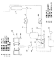
以下、図面に示す実施の形態により本発明を説明する。図1は本発明の一実施の形態に係る充填システムの全体の構成を簡略化して示す構成図であり、この充填システムで充填される液体(例えば、果肉等の固形物が混入した飲料)は、図示しない調合タンク内で調合され、クッションタンク2に送られて貯留される。なお、この実施の形態ではホットパック充填が行われるが、クッションタンク2に供給された時点では、液体は常温である。
The present invention will be described below with reference to embodiments shown in the drawings. FIG. 1 is a block diagram showing the overall structure of a filling system according to an embodiment of the present invention in a simplified manner. A liquid filled in the filling system (for example, a beverage mixed with solids such as pulp) , It is blended in a blending tank (not shown), sent to the
前記クッションタンク2に貯留された液体は、ポンプ4によって加熱手段としてのヒーター(熱交換器)6に送られ、所定の温度に加熱されて殺菌された後、配管8を通って脱気タンク10に送られる。この脱気タンク10は大気開放型であり、前記液体を所定の時間(例えば2分間)貯留することにより、中に含まれているエアを排出する。なお、充填液の性質や充填形態によっては、脱気タンク10を省略しても良いし、また、前記特許文献1に記載されている微加圧タンクを採用しても良い。
The liquid stored in the
前記脱気タンク10に貯留されてエアが排出された液体は、給液ポンプ12を介して給液管14に送られる。この給液管14(以下第1給液管と呼ぶ)にはバイパス通路16が接続され、さらにこのバイパス通路16には、切換バルブ18を介して第2の給液管20および戻し管22が接続されている。切換バルブ18は、通常の生産運転をしているときと、何らかのトラブル等が発生して停止した場合とで切り換えられるようになっており、停止検出センサ24からの検出信号に応じて制御装置26が出力する指令信号により切り換えられる。なお、停止検出センサ24は、例えば、充填装置28を回転させる駆動モータの停止信号や供給コンベヤ上の容器を検出するセンサ等を用いることができる。
The liquid stored in the
第1給液管14および第2給液管20は、ロータリジョイント30を介して充填装置28の充填液タンク32に接続されている。充填装置28の充填液タンク32は、図2に示すように、環状をしており、第1および第2の給液管14、20は、それぞれ、複数本(この実施の形態では3本)の分岐管14a、20aを介してこの充填液タンク32に接続されている。これら各給液管14、20の分岐管14a、20aは、それぞれ等間隔で配置され、かつ、第1給液管14の分岐管14aと第2給液管20の分岐管20aとが円周方向に交互に配置されている。充填装置28の充填液タンク32には、その外周側に円周方向等間隔で複数の充填手段(充填バルブ)34が設けられており、前記第1および第2の給液管14、20を介して充填液タンク28内に供給された充填液を、これら充填バルブ34を介して容器(図示せず)内に充填するようになっている。
The first
前記切換バルブ18に接続されている戻し管22は、ポンプ36およびクーラ(熱交換器)38を介してクッションタンク2に接続されており、後に説明するようにこの切換バルブ18を切り換えて第2給液管20と戻し管22とを接続したときには、充填液タンク32内の液体をクーラー38により冷却してクッションタンク2に戻すことができるようになっている。
The
以上の構成に係る充填システムの作動について説明する。通常の運転時には、切換バルブ18を切り換えることによりバイパス通路16と第2給液管20とを接続するとともに、戻り通路22を第1および第2の給液管14、20から遮断しており、脱気タンク10内の液体を第1給液管14および第2給液管20の双方に送液できるようにしている。
The operation of the filling system according to the above configuration will be described. During normal operation, the
容器内に充填される液体は、図示しない調合タンク内で調合され、クッションタンク2に送られて貯留される。この時点では液体は常温である。クッションタンク2内の液体は、ポンプ4によって吐出され、ヒーター6に送られて所定の温度まで加熱されて滅菌された後、脱気タンク10に送られる。脱気タンク10でエアが排出された液体は、給液ポンプ12によって充填液タンク32に供給される。
The liquid filled in the container is prepared in a preparation tank (not shown), sent to the
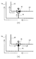
前記給液ポンプ12から吐出された液体は、第1給液管14と、この第1給液管14に接続されたバイパス通路16に送られる。さらにバイパス通路16は、図3(a)に示すように、第2給液管20に接続されるとともに、戻し管22とは遮断されているので、給液ポンプ12から吐出された液体は第1給液管14および第2給液管20の両方から、それぞれの分岐管14a、20aを介して充填装置28の充填液タンク32に供給される。
The liquid discharged from the
一方、充填装置28が停止した場合には、停止検出センサ24がこれを検出し、この検出信号によって制御装置26が切換バルブ18を切り換える。この場合には、図3(b)に示すように、第1給液管14に接続されているバイパス通路16が、第2給液管20および戻し通路22と遮断され、第2給液管20と戻し通路22とが接続される。
On the other hand, when the filling
この状態で、ポンプ4によってクッションタンク2から送り出された液体は、ヒーター6を通って加熱されて脱気タンク10に供給され、さらに、給液ポンプ12の作動により吐出された液体は、切換バルブ18によって第2給液管20には送られず、第1給液管14のみに送液されて充填液タンク32に供給される。充填装置28が停止しているので、充填液タンク32内に供給された液体は、充填バルブ34によって容器に充填されることはなく、第2給液管20および戻し管22から、クーラー38を通って冷却された後、クッションタンク2に戻される。ホット充填の場合には、充填液タンク32から還流する液体をそのままクッションタンク2に戻してしまうと、クッションタンク2内の温度が上昇してしまい、その後、ヒータ6を通過して供給される際にさらに液温が上昇して設定温度を超えてしまう。そのため、クッションタンク2から還流する液体をクーラー38によって冷却してクッションタンク2内に貯留されている液体の温度とほぼ同じ温度に下げるようにしている。
In this state, the liquid sent out from the
前述のように、充填装置28の停止時には、クッションタンク2、ヒータ6、脱気タンク10、第1給液管14、充填液タンク32、第2給液管20、戻し管22およびクーラー38を介してクッションタンク2に戻る閉回路を循環させるようにしているので、この充填システム内のほとんど全ての液体が設定温度を維持される。従って、運転再開時にブローしなければならない液量が極めて少なく(充填液タンク32から充填バルブ34に至る通路内の極めて少量である)、充填液のロスを最少にすることができる。また、運転停止中にも常に充填液を循環させているので、固形物入りの液体の場合でも、固形物が沈殿してしまうことがない。
As described above, when the filling
なお、前記実施の形態では、固形物入りの液体をホットパック充填する場合について説明したが、このような場合に限定されるものではなく、例えば、固形物入り飲料をホットパックでない常温充填する場合や、固形物を含む飲料以外の通常の飲料をホットパック充填する場合にも適用できることは言うまでもない。また、前記実施の形態では、ホットパック充填を行うためにヒータ6およびクーラー38を配置してあるが、常温での充填を行う場合には、ヒータ6およびクーラー38は必要なく、省略することもできる。この場合には、クッションタンク2から供給される液体は、直接脱気タンク10に送られ、また、充填装置28の停止時に還流される液体は、クーラー38を通らずそのままクッションタンク2に戻される。
In the above-described embodiment, the case of hot-pack filling a solid-containing liquid has been described.However, the present invention is not limited to such a case. Needless to say, the present invention can also be applied to hot-pack filling of a normal beverage other than a beverage containing a solid. In the above embodiment, the
4 送液手段(ポンプ)
6 送液手段(ヒータ)
10 送液手段(脱気タンク)
12 送液手段(給液ポンプ)
14 給液管(第1給液管)
16 バイパス通路
18 切換バルブ
20 給液管(第2給液管)
32 充填液タンク
34 充填手段(充填バルブ)
4 Liquid feeding means (pump)
6 Liquid feeding means (heater)
10 Liquid feeding means (deaeration tank)
12 Liquid feed means (Liquid feed pump)
14 Supply pipe (first supply pipe)
16
32 Filling
Claims (2)
少なくとも2本の給液管と、これら給液管を連通するバイパス通路と、このバイパス通路の回路を切り換える切換バルブとを設け、
正常運転時には、前記複数の給液管を介して充填液タンクに充填液を供給するとともに、充填停止時には、前記切換バルブを切り換えて、いずれかの給液管により充填液を供給し、他の給液管で充填液タンクから充填液を戻すことを特徴とする充填システム。 A filling liquid tank for storing the filling liquid, a filling means for filling the filling liquid into the container, a liquid supply pipe for supplying the filling liquid to the filling liquid tank, and a liquid feeding means for supplying the filling liquid to the liquid supply pipe In a filling system comprising
At least two liquid supply pipes, a bypass passage communicating these liquid supply pipes, and a switching valve for switching a circuit of the bypass passage;
During normal operation, the filling liquid is supplied to the filling liquid tank through the plurality of liquid supply pipes, and when the filling is stopped, the switching valve is switched to supply the filling liquid through one of the liquid supply pipes. A filling system for returning a filling liquid from a filling liquid tank by a supply pipe.
Priority Applications (1)
| Application Number | Priority Date | Filing Date | Title |
|---|---|---|---|
| JP2003340474A JP4265357B2 (en) | 2003-09-30 | 2003-09-30 | Filling system |
Applications Claiming Priority (1)
| Application Number | Priority Date | Filing Date | Title |
|---|---|---|---|
| JP2003340474A JP4265357B2 (en) | 2003-09-30 | 2003-09-30 | Filling system |
Publications (2)
| Publication Number | Publication Date |
|---|---|
| JP2005104531A JP2005104531A (en) | 2005-04-21 |
| JP4265357B2 true JP4265357B2 (en) | 2009-05-20 |
Family
ID=34535366
Family Applications (1)
| Application Number | Title | Priority Date | Filing Date |
|---|---|---|---|
| JP2003340474A Expired - Fee Related JP4265357B2 (en) | 2003-09-30 | 2003-09-30 | Filling system |
Country Status (1)
| Country | Link |
|---|---|
| JP (1) | JP4265357B2 (en) |
Families Citing this family (4)
| Publication number | Priority date | Publication date | Assignee | Title |
|---|---|---|---|---|
| JP5232568B2 (en) * | 2008-08-12 | 2013-07-10 | 三菱重工食品包装機械株式会社 | Aseptic filling equipment for carbonated beverages |
| JP6236698B2 (en) * | 2014-05-29 | 2017-11-29 | 三菱重工機械システム株式会社 | Liquid processing equipment |
| CN104129748A (en) * | 2014-06-15 | 2014-11-05 | 安徽皖峰蜂业集团有限公司 | Honey automatic material supply device |
| CN113501150B (en) * | 2021-07-12 | 2022-12-13 | 楚天科技股份有限公司 | Suspension filling control method, control system and filling system |
-
2003
- 2003-09-30 JP JP2003340474A patent/JP4265357B2/en not_active Expired - Fee Related
Also Published As
| Publication number | Publication date |
|---|---|
| JP2005104531A (en) | 2005-04-21 |
Similar Documents
| Publication | Publication Date | Title |
|---|---|---|
| US9706793B2 (en) | Sterilization treatment line and cleaning method thereof | |
| JP2009286497A (en) | Liquid filling method and apparatus | |
| US4416194A (en) | Beverage pasteurizing system | |
| CN102333719B (en) | Method for aseptic filling with carbon dioxide-containing liquid contents | |
| AU2006267772B2 (en) | Process and apparatus for producing beverage filled into container | |
| JP4265357B2 (en) | Filling system | |
| CN104703778A (en) | Method and device for producing containers | |
| WO2019230642A1 (en) | Method for maintaining positive pressure inside tank and device for maintaining positive pressure inside tank | |
| JP2002337988A (en) | High-temperature filling apparatus for liquid | |
| JP2021525102A (en) | Preparation of liquid beverage containing granules Sterilizer and preparation method | |
| JP4426723B2 (en) | Packaging material sterilization unit for fluid food packaging machine | |
| JP4366779B2 (en) | Beverage production line | |
| US4597945A (en) | Sterilization apparatus | |
| JP4241254B2 (en) | Liquid filling equipment, operation method thereof and heat insulation method | |
| JP5033159B2 (en) | Gas-liquid separation liquid cyclone and gas-liquid separation system | |
| CN110831888B (en) | Aseptic filling system | |
| SU1284493A1 (en) | Line for asptic preserving of liquid and puree-like products | |
| JPS59194745A (en) | Sterilizing and filling system capable of continuously treating liouid | |
| JP7250084B2 (en) | Control method of product liquid pipeline pressure | |
| JPH0910286A (en) | Device and method for heating and sterilizing product liquid | |
| EP4159665A1 (en) | System for dosing an aromatic product into containers | |
| JP7454034B1 (en) | Liquid product manufacturing system | |
| JP5090298B2 (en) | Liquid filling equipment and operating method thereof | |
| JPH10262627A (en) | Sterilizer | |
| JP3416188B2 (en) | Filling machine liquid level control device |
Legal Events
| Date | Code | Title | Description |
|---|---|---|---|
| A621 | Written request for application examination |
Free format text: JAPANESE INTERMEDIATE CODE: A621 Effective date: 20060426 |
|
| A977 | Report on retrieval |
Free format text: JAPANESE INTERMEDIATE CODE: A971007 Effective date: 20081215 |
|
| TRDD | Decision of grant or rejection written | ||
| A01 | Written decision to grant a patent or to grant a registration (utility model) |
Free format text: JAPANESE INTERMEDIATE CODE: A01 Effective date: 20090127 |
|
| A01 | Written decision to grant a patent or to grant a registration (utility model) |
Free format text: JAPANESE INTERMEDIATE CODE: A01 |
|
| A61 | First payment of annual fees (during grant procedure) |
Free format text: JAPANESE INTERMEDIATE CODE: A61 Effective date: 20090209 |
|
| R150 | Certificate of patent or registration of utility model |
Ref document number: 4265357 Country of ref document: JP Free format text: JAPANESE INTERMEDIATE CODE: R150 Free format text: JAPANESE INTERMEDIATE CODE: R150 |
|
| FPAY | Renewal fee payment (event date is renewal date of database) |
Free format text: PAYMENT UNTIL: 20120227 Year of fee payment: 3 |
|
| FPAY | Renewal fee payment (event date is renewal date of database) |
Free format text: PAYMENT UNTIL: 20120227 Year of fee payment: 3 |
|
| FPAY | Renewal fee payment (event date is renewal date of database) |
Free format text: PAYMENT UNTIL: 20130227 Year of fee payment: 4 |
|
| LAPS | Cancellation because of no payment of annual fees |