JP4263520B2 - Multi-plate clutch - Google Patents
Multi-plate clutch Download PDFInfo
- Publication number
- JP4263520B2 JP4263520B2 JP2003099708A JP2003099708A JP4263520B2 JP 4263520 B2 JP4263520 B2 JP 4263520B2 JP 2003099708 A JP2003099708 A JP 2003099708A JP 2003099708 A JP2003099708 A JP 2003099708A JP 4263520 B2 JP4263520 B2 JP 4263520B2
- Authority
- JP
- Japan
- Prior art keywords
- plate
- clutch
- friction plate
- clutch outer
- cylindrical portion
- Prior art date
- Legal status (The legal status is an assumption and is not a legal conclusion. Google has not performed a legal analysis and makes no representation as to the accuracy of the status listed.)
- Expired - Fee Related
Links
Images


Landscapes
- Mechanical Operated Clutches (AREA)
Description
【0001】
【発明の属する技術分野】
この発明は、クランク軸と変速機軸との間に介設される多板クラッチに関する。
【0002】
【従来の技術】
従来から、自動二輪車等の車両のエンジンに用いられる多板クラッチは、クランク軸により駆動されるクラッチアウタに複数の駆動摩擦板を取り付けると共にこれら複数の駆動摩擦板と交互に配置される従動摩擦板を変速機軸に取り付け、駆動摩擦板及び従動摩擦板を圧接あるいは圧接解除することでクラッチの断続が行われるようになっている。通常、クラッチアウタは有底円筒状に形成され、このクラッチアウタの外周壁に設けられた溝部と駆動摩擦板の外周部に設けられた突部とが係合することで、駆動摩擦板がクラッチアウタに圧接方向で摺動可能でかつ共に回転するように取り付けられている。そして、このような多板クラッチの中には、クラッチ断続時の応答性を高めるために乾式クラッチとして構成されるものがある(例えば、特許文献1参照。)。
【0003】
【特許文献1】
特公平2−570号公報
【0004】
【発明が解決しようとする課題】
ところで、上記従来の多板クラッチでは、駆動摩擦板を圧接方向にスムーズに摺動させるために溝部と突部との間隙を大きく設定する必要がある。
しかしながら、クラッチアウタはクランク軸により常時駆動されることから、前記間隙が大きいと駆動摩擦板が振れ回る場合があり、駆動摩擦板と従動摩擦板との接触によるフリクションを発生させクラッチの切れを悪化させてしまう。
また、前記間隙が大きくなれば溝部のクラッチアウタ回転方向の端面とこれに対向する突部の前記回転方向の端面との間隙も広がるため、クラッチ断続時やトルク変動時にはクラッチアウタと駆動摩擦板とが相対回転し溝部と突部とが衝突して打音を発生させる場合がある。これは、エンジン本体の外部に配置される乾式クラッチにとっては特に好ましくない。
そこでこの発明は、クラッチの切れを良好とし、かつクラッチアウタと駆動摩擦板との衝突による打音を低減できる多板クラッチを提供する。
【0005】
【課題を解決するための手段】
上記課題の解決手段として、請求項1に記載した発明は、クランク軸により回転駆動されるクラッチアウタ(例えば実施の形態におけるクラッチアウタ115)と、このクラッチアウタにその軸線方向に沿って摺動可能に取り付けられかつ共に回転する複数の駆動摩擦板(例えば実施の形態における駆動摩擦板16)と、これら複数の駆動摩擦板と交互に配置され変速機軸(例えば実施の形態における主軸5)と連動する従動摩擦板(例えば実施の形態における従動摩擦板17)とを備え、前記複数の駆動摩擦板及び従動摩擦板が前記軸線方向で圧接あるいは圧接解除されることで前記クランク軸と変速機軸との間の動力伝達を接続あるいは切断する多板クラッチ(例えば実施の形態における多板クラッチ101,201)において、前記クラッチアウタの外周部に前記軸線方向に沿う円筒部(例えば実施の形態における円筒部23、円筒軸部123a,223a)が複数設けられると共に、前記駆動摩擦板には前記各円筒部に対応する位置に摩擦板外周突部(例えば実施の形態における駆動板外周突起29)が設けられ、これら各摩擦板外周突部には前記円筒部を挿通させる挿通孔(例えば実施の形態における挿通孔30)が各々設けられ、前記各円筒部を介してクラッチアウタに前記駆動摩擦板が取り付けられ、前記各挿通孔は、その一部が摩擦板外周突部の外縁よりも駆動摩擦板の径方向外側にはみ出すように形成されることで、該各挿通孔の周長が半周以上残るように切り欠かれて駆動摩擦板の径方向外側に向かって開放されており、前記円筒部には、前記挿通孔に挿通されるカラー(例えば実施の形態におけるカラー部材31a,31b)が前記複数の駆動摩擦板毎に分割されて設けられ、これら分割されたカラーのうち前記クラッチアウタ寄りに配置されるカラー(例えば実施の形態におけるカラー部材31b)の前記クラッチアウタ側の端部が先細りのテーパ状に形成されていることを特徴とする。
【0006】
また、請求項2に記載した発明は、前記円筒部は前記クラッチアウタの外周部に前記軸線方向に沿って取り付けたボルト(例えば実施の形態におけるボルト123、スタッドボルト223)に設けられることを特徴とする。
【0007】
これらの多板クラッチによれば、駆動摩擦板が円筒部を介してクラッチアウタにその軸線方向に沿って摺動可能に取り付けられることで、駆動摩擦板の挿通孔と円筒部の外周面(円周面)とが摺接することとなり、駆動摩擦板が前記軸線方向に沿ってスムーズに摺動することができるため、駆動摩擦板と円筒部との間隙を小さく設定することが可能となる。
また、これらの多板クラッチによれば、クラッチアウタの外周部に複数設けられた円筒部を、駆動摩擦板の外周部に設けられた挿通孔に挿通させることで、駆動摩擦板がクラッチアウタにその軸線方向に沿って摺動可能に取り付けられかつ共に回転することとなる。
さらに、これらの多板クラッチによれば、駆動摩擦板に発熱等による変形が生じたとしても柔軟に対応することが可能となる。
【0008】
請求項3に記載した発明は、前記カラーは樹脂製であることを特徴とする。
【0011】
請求項4に記載した発明は、前記カラーは前記円筒部に対してその軸線回りに相対回転自在に取り付けられることを特徴とする。
【0012】
請求項5に記載した発明は、前記クラッチアウタ側に前記各摩擦板を押圧して圧接するプレッシャプレート(例えば実施の形態におけるプレッシャプレート26)を備え、該プレッシャプレートのクラッチアウタ側の側面には前記駆動摩擦板と同等の摩擦機能を有する環状板材の押圧リム部材(例えば実施の形態における押圧リム部材42)が接合されることを特徴とする。
【0013】
請求項6に記載した発明は、前記各円筒部のクラッチアウタと反対側の先端はリング状のクラッチアウタプレート(例えば実施の形態におけるクラッチアウタプレート47)により連結され、該クラッチアウタプレートには前記各円筒部に対応するボス部(例えば実施の形態におけるボス部48)が設けられ、該各ボス部が前記各円筒部に締結されることを特徴とする。
【0015】
【発明の実施の形態】
以下、この発明の実施の形態を図面に基づいて説明する。
図1に示すように、多板クラッチ1は、クランクケース2にボールベアリング3を介して回転可能に支持される変速機4の主軸(変速機軸)5の一端(この実施の形態においては右側端)に設けられる。主軸5は図示しないクランク軸と平行に配置され、かつこの主軸5と平行に変速機4のカウンタ軸6が配置される。クランク軸にはドライブギヤ7が一体に設けられ、主軸5にはドライブギヤ7と噛み合うドリブンギヤ8がニードルベアリング9を介して回転自在に支持される。ここで、クランクケース2の右側壁10は左側(クランクケース2内側)に変化して収容部11を形成し、この収容部11内に多板クラッチ1が配置される。つまり、多板クラッチ1はクランクケース2の外部に配置されており、クランクケース2内の油室12から隔離された乾式クラッチとして構成される。なお、収容部11の右側(クランクケース2外側)開口部にはクラッチカバー13が取り付けられる。
【0016】
多板クラッチ1は、ドリブンギヤ8と共にクランク軸により常時回転駆動されるクラッチアウタ15と、このクラッチアウタ15と連動する複数の駆動摩擦板16と、これら複数の駆動摩擦板16と交互に配置され主軸5と連動する従動摩擦板17とを備え、これら駆動摩擦板16及び従動摩擦板17が圧接又は圧接解除されることでクランク軸と主軸5との間の動力伝達を接続あるいは切断するものである。
【0017】
図3を併せて参照して説明すると、クラッチアウタ15は主軸5と回転軸線を共有する略円盤状の部材であり、その中央には主軸5の挿通孔18が設けられる。また、クラッチアウタ15の外周側フランジ部19は挿通孔18周辺の内周部20に対して右側に段差状に変化するように形成される。このクラッチアウタ15がドリブンギヤ8と収容部11の底壁11aを挟んで近接配置され、クラッチアウタ15の内周部20とドリブンギヤ8の内周部8aとが複数のボルト21により結合される。また、クラッチアウタ15にはその外縁から径方向外側に突出するアウタ外周突部(外周部)22が円周方向で等間隔に複数(この実施の形態においては五つ)設けられると共に、これら各アウタ外周突部22には主軸5及びクラッチアウタ15の軸線Cに沿って右側に突出する円筒部23が各々設けられる。なお、クラッチアウタ15の外周側フランジ部19よりも径方向内側の部位には肉抜き孔24が複数設けられると共に前記ボルト21の挿通孔25が複数設けられる。
【0018】
クラッチアウタ15の右側には二枚の駆動摩擦板16及び三枚の従動摩擦板17が交互に積層され、これら各摩擦板16,17の右側にプレッシャプレート26が配置される。つまり、多板クラッチ1では、クラッチアウタ15から右側へ、従動摩擦板17、駆動摩擦板16、従動摩擦板17、駆動摩擦板16、従動摩擦板17、プレッシャプレート26の順で配置される。そして、各摩擦板16,17、及びプレッシャプレート26が皿バネ27のバネ荷重により軸線Cに沿ってクラッチアウタ15側(左側)に向かって押圧されることで、クラッチアウタ15、各摩擦板16,17、及びプレッシャプレート26が圧接される。また、この圧接の解除は、不図示のクラッチレリーズを作動させ主軸5内に挿通されるリフタロッド28等を介してプレッシャプレート26を皿バネ27のバネ荷重に抗して右側に移動させることで行われる。
【0019】
図1、図4示すように、駆動摩擦板16はクラッチアウタ15の外周側フランジ部19と略同径でかつ径方向の幅も略同一に形成される環状板材である。駆動摩擦板16には前記各アウタ外周突部22に対応する位置に摩擦板外周突部(外周部)29が設けられると共に、これら各摩擦板外周突部29には前記円筒部23を挿通させる挿通孔30が各々設けられる。ここで、各円筒部23にはカラー部材(カラー)31が設けられ、このカラー部材31により形成される軸線Cと平行な円周面に摺接するように挿通孔30が形成される。
【0020】
カラー部材31は、軸線C方向(左右方向)で連なる二つのカラー部材31a,32bに分割され、各カラー部材31a,31bが各駆動摩擦板16のそれぞれの挿通孔30に挿通される。つまり、右側のカラー部材31aは右側の駆動摩擦板16の挿通孔30に挿通され、左側のカラー部材31bは左側の駆動摩擦板16の挿通孔30に挿通される。言い換えれば、カラー部材31は複数の駆動摩擦板16毎に分割して設けられる。そして、各挿通孔30に円筒部23及びカラー部材31が挿通されることで、駆動摩擦板16が円筒部23及びカラー部材31を介してクラッチアウタ15に軸線C方向に沿って摺動可能に取り付けられ、かつクラッチアウタ15と駆動摩擦板16とが共に回転することとなる。ここで、各カラー部材31a,31bは緩衝性を有する樹脂製とされ、駆動摩擦板16との衝突による打音の発生を効果的に低減できる。なお、カラー部材31bの外周部の左寄り(クラッチアウタ15寄り)の部位は左先端側を先細りとするテーパ状に形成される。
【0021】
また、各挿通孔30はその一部が摩擦板外周突部29の外縁よりも駆動摩擦板16の径方向外側にはみ出すように形成される。つまり、各挿通孔30の一部が切り欠かれて駆動摩擦板16の径方向外側に向かって開放される。ここで、各挿通孔30はその周長が半周以上残るように切り欠かれている。これにより、摩擦板外周突部29は対向するフック状に形成され、クラッチアウタ15の円筒部23及びカラー部材31を挟み込むように保持することとなる。
【0022】
図1、図5に示すように、従動摩擦板17もクラッチアウタ15の外周側フランジ部19と略同径に形成されるもので、摩擦板本体33とボス部材34とを複数のリベット35を介して一体に結合して構成されるものである。摩擦板本体33の表裏面には摩擦板本体33と同一材料の環状板材であるリム部材36,36が接合され、これら各リム部材36がクラッチアウタ15の外周側フランジ部19、駆動摩擦板16、プレッシャプレート26とそれぞれ対向配置される。また、摩擦板本体33のリム部材36よりも内周側の部位は適宜切り欠かれて複数(この実施の形態では六つ)のアーム部37が形成される。なお、これら各アーム部37の内周側端部には前記リベット35が各々配設される。ボス部材34の内周部には主軸5の右側端部に形成された主軸側スプライン5aに嵌合する摩擦板側スプライン38が形成され、これら各スプライン5a,38が嵌合することで、従動摩擦板17が主軸5にその軸線C方向に沿って摺動可能に取り付けられ、かつ従動摩擦板17と主軸5とが共に回転することとなる。
【0023】
図1、図2に示すように、主軸5の先端部には第一皿バネホルダ39が固定され、この第一皿バネホルダ39にはボールベアリング40を介して第二皿バネホルダ41が保持される。そして、第二皿バネホルダ41が皿バネ27の中央部に嵌合し左側に押圧することで、皿バネ27の外周部が所定のバネ荷重でプレッシャプレート26を軸線Cに沿って左側、つまりクラッチアウタ15側に付勢するようになっている。ここで、プレッシャプレート26は軸線Cを中心としたリング状に形成されるもので、軽量化のためにアルミ材で構成されるものである。また、プレッシャプレート26の左側面には駆動摩擦板16と同等の摩擦機能を有する鉄製の環状板材の押圧リム部材42が接合される。プレッシャプレート26にはその内周側から円形留め金43を介してリフタプレート44が係合され、このリフタプレート44の中央部にボールベアリング45を介してリフタピン46が装着される。リフタピン46は前記リフタロッド28の右側端に接続され、リフタロッド28の駆動によりボールベアリング45を介してリフタプレート44を軸線Cに沿って右側に移動させるものである。そして、リフタプレート44が右側に移動することで、円形留め金43を介してプレッシャプレート26が皿バネ27のバネ荷重に抗して移動することとなる。
【0024】
クラッチアウタ15の各円筒部23の右側先端はリング状のクラッチアウタプレート47により連結される。クラッチアウタプレート47には各円筒部23に対応するボス部48が設けられ、これらボス部48に軸線Cに沿って挿通されたボルト49が円筒部23の右側先端に形成されたボルト孔に締め込まれる。ボス部48は円筒部23よりも大径であり、このボス部48によってカラー部材31の円筒部23からの脱落が規制される。なお、カラー部材31は円筒部23に対してその軸線回りに相対回転自在に取り付けられる。
【0025】
次に、作用について説明する。
まず、クランク軸が回転駆動すると、これに伴いドライブギヤ7及びドリブンギヤ8を介して多板クラッチ1のクラッチアウタ15が回転駆動される。このとき、多板クラッチ1が接続状態であれば、皿バネ27のバネ荷重によりクラッチアウタ15、各摩擦板16,17、及びプレッシャプレート26が圧接され、これらが一体に回転駆動される。これにより、従動摩擦板17に係合する変速機4の主軸5が回転駆動される、つまり、クランク軸の回転駆動力(トルク)が変速機4の主軸5に伝達される。
【0026】
また、多板クラッチ1を接続状態から切断状態とする場合には、不図示のクラッチレリーズが作動することでリフタロッド28、リフタピン46、及びボールベアリング45を介してリフタプレート44が右側に押圧され、かつ円形留め金43を介してプレッシャプレート26が皿バネ27のバネ荷重に抗して右側に移動する。これにより、クラッチアウタ15、各摩擦板16,17、及びプレッシャプレート26の圧接が解除され、多板クラッチ1が切断状態となってクランク軸と変速機4の主軸5との間の動力伝達が切断される。
【0027】
ここで、駆動摩擦板16は、円筒部23及びカラー部材31を介してクラッチアウタ15にその軸線C方向に沿って摺動可能に取り付けられてかつ共に回転するようになっている。このとき、駆動摩擦板16の挿通孔30とカラー部材31の円周面とが摺接することとなり、駆動摩擦板16が軸線C方向に沿ってスムーズに摺動することができるため、駆動摩擦板16とカラー部材31との間隙を小さく設定することが可能となる。
【0028】
また、従来のクラッチアウタは有底円筒状に形成されその外周壁に形成された溝部に駆動摩擦板を係合させるように構成されていたが、多板クラッチ1においては、ディスク状のクラッチアウタ15に前記外周壁に代わり複数の円筒部23が突設され、これら各円筒部23に駆動摩擦板16を係合させるように構成されている。これにより、各駆動摩擦板16をクラッチアウタ15にその軸線C方向に沿って摺動可能に取り付けかつ共に回転させるようになっている。
【0029】
さらに、各挿通孔30はその一部が切り欠かれて駆動摩擦板16の径方向外側に向かって開放されることで、クラッチアウタ15の円筒部23及びカラー部材31を挟み込んで保持するように形成されることとなり、駆動摩擦板16に発熱等による変形が生じたとしても柔軟に対応することが可能となる。
【0030】
上記実施の形態によれば、駆動摩擦板16とカラー部材31との間隙を小さく設定することが可能となり、クラッチ切断状態において常時回転駆動されるクラッチアウタ15と共に回転する駆動摩擦板16の振れ回りを抑えてクラッチの切れを良好にすることができる。また、クラッチ断続時やトルク変動時において、クラッチアウタ15及び駆動摩擦板16の相対回転方向で挿通孔30とカラー部材31とが衝突することによる打音の発生も抑えることができる。これは、多板クラッチ1がクランクケース2外部に配置される乾式クラッチである場合には特に好適である。
【0031】
また、従来の有底円筒状のクラッチアウタを有する多板クラッチと比較して、クラッチアウタ15を小型軽量化することができると共に、駆動摩擦板16及び従動摩擦板17の冷却性を向上させクラッチの滑りを抑えることができる。
さらに、駆動摩擦板16に発熱等による変形が生じたとしても柔軟に対応することが可能となり、駆動摩擦板16及び従動摩擦板17を均等に圧接させクラッチ性能を安定させることができる。
【0032】
しかも、円筒部23には駆動摩擦板16毎に分割されたカラー部材31が各々回転自在に取り付けられることで、各駆動摩擦板16の公差による挿通孔30のずれやクラッチアウタ15及び駆動摩擦板16の相対回転にも柔軟に対応することができ、駆動摩擦板16をより一層スムーズに摺動させることができる。また、円筒部23に緩衝性を有する樹脂製のカラー部材31が設けられるため、駆動摩擦板16が衝突することによる打音の発生を効果的に低減することができる。
【0033】
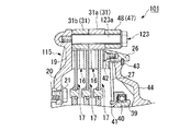
次に、この発明の第二、第三の実施の形態を図6、図7に基づいて説明する。なお、上記第一の実施の形態と同一部分には同一符号を付して説明を省略する。図6に示す多板クラッチ(第二実施形態)101は、前記クラッチアウタ15に対して円筒部23を廃した構成を有するクラッチアウタ115に前記軸線C方向に沿ってボルト123が取り付けられ、該ボルト123を介してクラッチアウタ115に前記駆動摩擦板16が取り付けられるものである。また、図7に示す多板クラッチ(第3実施形態)201は、前記クラッチアウタ115に前記軸線C方向に沿ってスタッドボルト223が植設され、該スタッドボルト223を介してクラッチアウタ215に前記駆動摩擦板16が取り付けられるものである。ここで、多板クラッチ101,201の駆動摩擦板16の前記挿通孔30は各ボルト123,223に対応して設けられる。
【0034】
各ボルト123,223はその左側端部が各々クラッチアウタ115,115に固定される。また、各ボルト123,223には各々円筒軸部123a,223bが設けられ、これら各円筒軸部123a,223aには軸線Cと平行な円周面を形成する前記カラー部材31が各ボルト123,223の軸線回りに回転自在に取り付けられる。そして、各カラー部材31が形成する円周面に各挿通孔30が摺接するようになっている。各ボルト123,223の右側先端は前記クラッチアウタプレート47により連結され、かつクラッチアウタプレート47により各カラー部材31の脱落が規制される。なお、スタッドボルト223の右側端部にはナット223bが取り付けられる。
【0035】
上記第二、第三の実施の形態においても、前記第一の実施の形態と同様、クラッチの切れを良好とし、かつ挿通孔30とカラー部材31との衝突による打音の発生を抑えることができる。また、クラッチアウタ115を小型軽量化できると共にクラッチ性能を安定させることができる。
【0036】
なお、この発明は上記各実施の形態に限られるものではなく、例えば、カラー部材31を設けずに円筒部23又は各円筒軸部123a,223aが形成する円周面と摺接するように駆動摩擦板16の挿通孔30を設けることでも、駆動摩擦板16が軸線C方向に沿ってスムーズに摺動することとなるため、クラッチの切れを良好とし、かつ挿通孔30と円筒部23又は各円筒軸部123a,223aとの衝突による打音の発生を抑えることができる。同様に、各カラー部材31が円筒部23又は各円筒軸部123a,223aに固定されるようにしてもよい。また、挿通孔30を切り欠かない構成としても駆動摩擦板16をスムーズに摺動させることが可能である。さらにまた、各挿通孔30をその直径と略同一幅で切り欠く、あるいは挿通孔30を長孔とすることで、駆動摩擦板16の変形にさらに柔軟に対応することができる。
そして、上記各実施の形態における構成はこの発明の一例であり、乾式クラッチに限定されるものではなく、発明の主旨の範囲内で適宜変更可能である。
【0037】
【発明の効果】
以上説明してきたように、本願発明によれば、駆動摩擦板が円筒部を介してクラッチアウタにその軸線方向に沿って摺動可能に取り付けられることで、駆動摩擦板と円筒部との間隙を小さく設定することが可能となるため、駆動摩擦板の振れ回りを抑えてクラッチの切れを良好にすることができると共に、クラッチ断続時やトルク変動時においてクラッチアウタと駆動摩擦板とが衝突することによる打音の発生も抑えることができる。また、クラッチアウタと駆動摩擦板との間に緩衝用のカラー部材を容易に介設することができ、より一層前記打音の低減を図ることができる。
【0038】
本願発明によれば、クラッチアウタの外周部に複数設けられた円筒部と、駆動摩擦板の外周部に設けられた挿通孔とを嵌合させることで、クラッチアウタに駆動摩擦板を取り付ける構成としたことで、従来の有底円筒状のクラッチアウタと比較してクラッチアウタを小型軽量化することができると共に、駆動摩擦板及び従動摩擦板の冷却性を向上させてクラッチの滑りを抑えることができる。
【0039】
本願発明によれば、駆動摩擦板の変形に柔軟に対応できるため、駆動摩擦板及び従動摩擦板を均等に圧接させることができ、クラッチ性能を安定させることができる。
【0040】
本願発明によれば、円筒部と駆動摩擦板との間に樹脂製のカラーを介設させることで、クラッチアウタと駆動摩擦板との衝突による打音を効果的に低減することができる。
【図面の簡単な説明】
【図1】 この発明の実施の形態における多板クラッチ及びその周辺の断面図である。
【図2】 多板クラッチの正面図(軸線方向から見た図)である。
【図3】 クラッチアウタの正面図である。
【図4】 駆動摩擦板の正面図である。
【図5】 従動摩擦板の正面図である。
【図6】 この発明の第二の実施の形態における多板クラッチの要部の断面図である。
【図7】 この発明の第三の実施の形態における多板クラッチの要部の断面図である。
【符号の説明】
1,101,201 多板クラッチ
5 主軸(変速機軸)
15,115 クラッチアウタ
16 駆動摩擦板
17 従動摩擦板
23 円筒部
30 挿通孔
31 カラー部材(カラー)
123 ボルト
223 スタッドボルト(ボルト)[0001]
BACKGROUND OF THE INVENTION
The present invention relates to a multi-plate clutch interposed between a crankshaft and a transmission shaft.
[0002]
[Prior art]
2. Description of the Related Art Conventionally, a multi-plate clutch used in a vehicle engine such as a motorcycle has a plurality of drive friction plates attached to a clutch outer driven by a crankshaft and is alternately arranged with the plurality of drive friction plates. Is attached to the transmission shaft, and the drive friction plate and the driven friction plate are brought into pressure contact with each other or released from the pressure contact, whereby the clutch is engaged and disengaged. Normally, the clutch outer is formed in a bottomed cylindrical shape, and a groove provided on the outer peripheral wall of the clutch outer engages with a protrusion provided on the outer peripheral portion of the drive friction plate, so that the drive friction plate is engaged with the clutch. The outer part is slidable in the press-contact direction and is attached so as to rotate together. Among such multi-plate clutches, there is one configured as a dry-type clutch in order to enhance responsiveness when the clutch is engaged (see, for example, Patent Document 1).
[0003]
[Patent Document 1]
Japanese Examined Patent Publication No. 2-570 [0004]
[Problems to be solved by the invention]
By the way, in the conventional multi-plate clutch, it is necessary to set a large gap between the groove and the protrusion in order to smoothly slide the drive friction plate in the press-contact direction.
However, since the clutch outer is always driven by the crankshaft, if the gap is large, the driving friction plate may sway, and friction due to contact between the driving friction plate and the driven friction plate is generated, thereby deteriorating the clutch disengagement. I will let you.
Further, if the gap becomes larger, the gap between the end surface of the groove in the rotation direction of the clutch outer and the end surface of the protrusion facing the rotation direction in the rotation direction also increases, so the clutch outer and the drive friction plate May rotate relative to each other and the groove and the projection may collide to generate a hitting sound. This is not particularly preferable for a dry clutch disposed outside the engine body.
Therefore, the present invention provides a multi-plate clutch that can improve clutch disengagement and can reduce the hitting sound caused by the collision between the clutch outer and the drive friction plate.
[0005]
[Means for Solving the Problems]
As a means for solving the above problems, the invention described in claim 1 is a clutch outer (for example, the clutch outer 115 in the embodiment) that is rotationally driven by a crankshaft, and is slidable along the axial direction of the clutch outer. A plurality of driving friction plates (for example, the driving
[0006]
According to a second aspect of the present invention, the cylindrical portion is provided on a bolt (for example, the
[0007]
According to these multi-plate clutches, the drive friction plate is attached to the clutch outer through the cylindrical portion so as to be slidable along the axial direction thereof, so that the insertion hole of the drive friction plate and the outer peripheral surface of the cylindrical portion (circle) Since the driving friction plate can slide smoothly along the axial direction, the gap between the driving friction plate and the cylindrical portion can be set small.
Further, according to these multi-plate clutches, the driving friction plate is attached to the clutch outer by inserting a plurality of cylindrical portions provided on the outer peripheral portion of the clutch outer through insertion holes provided on the outer peripheral portion of the driving friction plate. It will be slidably mounted along its axial direction and will rotate together.
Further, according to these multi-plate clutches, even if the drive friction plate is deformed due to heat generation or the like, it is possible to flexibly cope with it.
[0008]
The invention described in
[0011]
The invention described in
[0012]
The invention described in
[0013]
According to the sixth aspect of the present invention, the tip of each cylindrical portion opposite to the clutch outer is connected by a ring-shaped clutch outer plate (for example, the clutch
[0015]
DETAILED DESCRIPTION OF THE INVENTION
Hereinafter, embodiments of the present invention will be described with reference to the drawings.
As shown in FIG. 1, the multi-plate clutch 1 includes one end (a right end in this embodiment) of a main shaft (transmission shaft) 5 of a
[0016]
The multi-plate clutch 1 includes a clutch outer 15 that is always driven to rotate by a crankshaft together with the driven
[0017]
Referring to FIG. 3 as well, the clutch outer 15 is a substantially disk-shaped member that shares the rotation axis with the
[0018]
Two
[0019]
As shown in FIG. 1 and FIG. 4, the
[0020]
The
[0021]
Further, each
[0022]
As shown in FIGS. 1 and 5, the driven
[0023]
As shown in FIGS. 1 and 2, a first
[0024]
The right end of each
[0025]
Next, the operation will be described.
First, when the crankshaft is rotationally driven, the clutch outer 15 of the multi-plate clutch 1 is rotationally driven through the drive gear 7 and the driven
[0026]
Further, when the multi-plate clutch 1 is changed from the connected state to the disconnected state, the
[0027]
Here, the
[0028]
Further, the conventional clutch outer is configured to have a bottomed cylindrical shape and a drive friction plate to be engaged with a groove formed on the outer peripheral wall thereof. However, in the multi-plate clutch 1, a disc-shaped clutch outer is provided. 15, a plurality of
[0029]
Further, a part of each
[0030]
According to the above-described embodiment, the gap between the
[0031]
Further, the clutch outer 15 can be reduced in size and weight as compared with a conventional multi-plate clutch having a bottomed cylindrical clutch outer, and the cooling performance of the driving
Further, even if the driving
[0032]
In addition, the
[0033]
Next, second and third embodiments of the present invention will be described with reference to FIGS. Note that the same parts as those in the first embodiment are denoted by the same reference numerals and description thereof is omitted. A multi-plate clutch (second embodiment) 101 shown in FIG. 6 has a
[0034]
The left ends of the
[0035]
Also in the second and third embodiments, as in the first embodiment, it is possible to make the clutch disengaged well and to suppress the generation of hitting sound due to the collision between the
[0036]
The present invention is not limited to the above-described embodiments. For example, the drive friction is made so as to be in sliding contact with the circumferential surface formed by the
And the structure in each said embodiment is an example of this invention, and is not limited to a dry clutch, It can change suitably within the range of the main point of invention.
[0037]
【The invention's effect】
As described above, according to the present invention, the driving friction plate that is slidably mounted along the axial direction to the clutch outer through the cylindrical portion, the gap between the driving friction plates and the cylindrical portion Since it can be set to a small value, it is possible to suppress the swing of the drive friction plate to improve the clutch disengagement, and the clutch outer and the drive friction plate collide when the clutch is engaged or when the torque fluctuates. It is also possible to suppress the occurrence of hitting sound. In addition, a cushioning collar member can be easily interposed between the clutch outer and the drive friction plate, so that the hitting sound can be further reduced.
[0038]
According to the invention of the present application , the drive friction plate is attached to the clutch outer by fitting a plurality of cylindrical portions provided on the outer periphery of the clutch outer and the insertion holes provided on the outer periphery of the drive friction plate. As a result, the clutch outer can be reduced in size and weight as compared with the conventional bottomed cylindrical clutch outer, and the cooling performance of the driving friction plate and the driven friction plate can be improved to suppress slipping of the clutch. it can.
[0039]
According to the present invention, since it is possible to flexibly cope with the deformation of the drive friction plate, the drive friction plate and the driven friction plate can be pressed uniformly, and the clutch performance can be stabilized.
[0040]
According to the present invention , the hitting sound caused by the collision between the clutch outer and the drive friction plate can be effectively reduced by providing the resin collar between the cylindrical portion and the drive friction plate.
[Brief description of the drawings]
FIG. 1 is a cross-sectional view of a multi-plate clutch and its surroundings according to an embodiment of the present invention.
FIG. 2 is a front view of the multi-plate clutch (viewed from the axial direction).
FIG. 3 is a front view of a clutch outer.
FIG. 4 is a front view of a drive friction plate.
FIG. 5 is a front view of a driven friction plate.
FIG. 6 is a cross-sectional view of a main part of a multi-plate clutch according to a second embodiment of the present invention.
FIG. 7 is a cross-sectional view of a main part of a multi-plate clutch according to a third embodiment of the present invention.
[Explanation of symbols]
1,101,201
15, 115 Clutch outer 16
Claims (6)
前記クラッチアウタの外周部に前記軸線方向に沿う円筒部が複数設けられると共に、前記駆動摩擦板には前記各円筒部に対応する位置に摩擦板外周突部が設けられ、これら各摩擦板外周突部には前記円筒部を挿通させる挿通孔が各々設けられ、前記各円筒部を介してクラッチアウタに前記駆動摩擦板が取り付けられ、
前記各挿通孔は、その一部が摩擦板外周突部の外縁よりも駆動摩擦板の径方向外側にはみ出すように形成されることで、該各挿通孔の周長が半周以上残るように切り欠かれて駆動摩擦板の径方向外側に向かって開放されており、
前記円筒部には、前記挿通孔に挿通されるカラーが前記複数の駆動摩擦板毎に分割されて設けられ、
これら分割されたカラーのうち前記クラッチアウタ寄りに配置されるカラーの前記クラッチアウタ側の端部が先細りのテーパ状に形成されていることを特徴とする多板クラッチ。A clutch outer that is rotationally driven by a crankshaft, a plurality of drive friction plates that are slidably attached to the clutch outer along the axial direction thereof, and that rotate together, and a plurality of drive friction plates that are alternately arranged and changed in speed. A driven friction plate interlocking with the machine shaft, and connecting or disconnecting the power transmission between the crankshaft and the transmission shaft by the plurality of drive friction plates and the driven friction plate being pressed or released in the axial direction. In a multi-plate clutch that
A plurality of cylindrical portions along the axial direction are provided on the outer peripheral portion of the clutch outer, and a friction plate outer peripheral protrusion is provided on the drive friction plate at a position corresponding to each cylindrical portion. Each part is provided with an insertion hole through which the cylindrical part is inserted, and the drive friction plate is attached to the clutch outer via each cylindrical part,
Each of the insertion holes is formed so that a part of the insertion hole protrudes radially outward of the driving friction plate from the outer edge of the friction plate outer peripheral projection, so that the circumferential length of each insertion hole remains more than half a circumference. It is open to the outside in the radial direction of the drive friction plate ,
In the cylindrical portion, a collar inserted through the insertion hole is divided and provided for each of the plurality of driving friction plates,
The multi-plate clutch is characterized in that an end portion on the clutch outer side of a collar arranged near the clutch outer among these divided collars is formed in a tapered shape .
Priority Applications (1)
| Application Number | Priority Date | Filing Date | Title |
|---|---|---|---|
| JP2003099708A JP4263520B2 (en) | 2003-04-02 | 2003-04-02 | Multi-plate clutch |
Applications Claiming Priority (1)
| Application Number | Priority Date | Filing Date | Title |
|---|---|---|---|
| JP2003099708A JP4263520B2 (en) | 2003-04-02 | 2003-04-02 | Multi-plate clutch |
Publications (2)
| Publication Number | Publication Date |
|---|---|
| JP2004308699A JP2004308699A (en) | 2004-11-04 |
| JP4263520B2 true JP4263520B2 (en) | 2009-05-13 |
Family
ID=33464069
Family Applications (1)
| Application Number | Title | Priority Date | Filing Date |
|---|---|---|---|
| JP2003099708A Expired - Fee Related JP4263520B2 (en) | 2003-04-02 | 2003-04-02 | Multi-plate clutch |
Country Status (1)
| Country | Link |
|---|---|
| JP (1) | JP4263520B2 (en) |
Families Citing this family (1)
| Publication number | Priority date | Publication date | Assignee | Title |
|---|---|---|---|---|
| CN110889252B (en) * | 2019-12-05 | 2023-04-28 | 麦格纳动力总成(江西)有限公司 | Wet type double-clutch transmission clutch friction plate tolerance analysis method |
-
2003
- 2003-04-02 JP JP2003099708A patent/JP4263520B2/en not_active Expired - Fee Related
Also Published As
| Publication number | Publication date |
|---|---|
| JP2004308699A (en) | 2004-11-04 |
Similar Documents
| Publication | Publication Date | Title |
|---|---|---|
| JP6498271B2 (en) | Clutch system and power train comprising a twin clutch and a CSC including an axial CSC bearing having a step for holding the CSC | |
| EP1378683A2 (en) | Flywheel device for prime mover | |
| JP5444153B2 (en) | Clutch device | |
| JP4297194B2 (en) | Power transmission mechanism | |
| US8631920B2 (en) | System and method for attaching a dual clutch to a flywheel | |
| US8875859B2 (en) | Hydraulic clutch and transmission device provided with the same | |
| US8371948B2 (en) | Flywheel device | |
| KR20020023137A (en) | Starting clutch | |
| JP2008082397A (en) | Power transmission device | |
| US20230272825A1 (en) | Power transmission apparatus | |
| JP3585868B2 (en) | Clutch outer | |
| JP4263520B2 (en) | Multi-plate clutch | |
| US20130333997A1 (en) | Transmission device | |
| US10480591B2 (en) | Coupling arrangement for the powertrain of a vehicle | |
| JP4322038B2 (en) | Dry multi-plate clutch | |
| US6286648B1 (en) | Lockup device of a torque converter | |
| JP2019090429A (en) | Clutch device | |
| GB2398610A (en) | Clutch having a hub with protrusions engaging closed apertures in friction discs | |
| JP6958502B2 (en) | Automatic transmission | |
| JP2562086Y2 (en) | Variable inertia flywheel | |
| US10690194B2 (en) | Clutch assembly, kit, and method | |
| JP2021162114A (en) | Clutch device | |
| EP1780433B1 (en) | Clutch including damper springs | |
| JP2021089017A (en) | Clutch device | |
| JP2020101271A (en) | Automatic transmission |
Legal Events
| Date | Code | Title | Description |
|---|---|---|---|
| A621 | Written request for application examination |
Free format text: JAPANESE INTERMEDIATE CODE: A621 Effective date: 20051201 |
|
| A977 | Report on retrieval |
Free format text: JAPANESE INTERMEDIATE CODE: A971007 Effective date: 20080501 |
|
| A131 | Notification of reasons for refusal |
Free format text: JAPANESE INTERMEDIATE CODE: A131 Effective date: 20080701 |
|
| A521 | Written amendment |
Free format text: JAPANESE INTERMEDIATE CODE: A523 Effective date: 20080827 |
|
| A02 | Decision of refusal |
Free format text: JAPANESE INTERMEDIATE CODE: A02 Effective date: 20081104 |
|
| A521 | Written amendment |
Free format text: JAPANESE INTERMEDIATE CODE: A523 Effective date: 20081217 |
|
| A911 | Transfer of reconsideration by examiner before appeal (zenchi) |
Free format text: JAPANESE INTERMEDIATE CODE: A911 Effective date: 20090116 |
|
| TRDD | Decision of grant or rejection written | ||
| A01 | Written decision to grant a patent or to grant a registration (utility model) |
Free format text: JAPANESE INTERMEDIATE CODE: A01 Effective date: 20090203 |
|
| A01 | Written decision to grant a patent or to grant a registration (utility model) |
Free format text: JAPANESE INTERMEDIATE CODE: A01 |
|
| A61 | First payment of annual fees (during grant procedure) |
Free format text: JAPANESE INTERMEDIATE CODE: A61 Effective date: 20090212 |
|
| FPAY | Renewal fee payment (event date is renewal date of database) |
Free format text: PAYMENT UNTIL: 20120220 Year of fee payment: 3 |
|
| R150 | Certificate of patent or registration of utility model |
Free format text: JAPANESE INTERMEDIATE CODE: R150 |
|
| FPAY | Renewal fee payment (event date is renewal date of database) |
Free format text: PAYMENT UNTIL: 20130220 Year of fee payment: 4 |
|
| LAPS | Cancellation because of no payment of annual fees |