JP4262726B2 - Game controller and game system - Google Patents
Game controller and game system Download PDFInfo
- Publication number
- JP4262726B2 JP4262726B2 JP2006122681A JP2006122681A JP4262726B2 JP 4262726 B2 JP4262726 B2 JP 4262726B2 JP 2006122681 A JP2006122681 A JP 2006122681A JP 2006122681 A JP2006122681 A JP 2006122681A JP 4262726 B2 JP4262726 B2 JP 4262726B2
- Authority
- JP
- Japan
- Prior art keywords
- control unit
- operation data
- unit
- game
- data
- Prior art date
- Legal status (The legal status is an assumption and is not a legal conclusion. Google has not performed a legal analysis and makes no representation as to the accuracy of the status listed.)
- Active
Links
- 230000001133 acceleration Effects 0.000 claims description 108
- 238000003384 imaging method Methods 0.000 claims description 77
- 238000004364 calculation method Methods 0.000 claims description 51
- 238000012545 processing Methods 0.000 claims description 45
- 230000005540 biological transmission Effects 0.000 claims description 35
- 230000004044 response Effects 0.000 claims description 9
- 238000003825 pressing Methods 0.000 claims description 6
- 230000009471 action Effects 0.000 claims description 2
- 238000004891 communication Methods 0.000 description 21
- 230000036544 posture Effects 0.000 description 19
- 230000006870 function Effects 0.000 description 16
- 210000004247 hand Anatomy 0.000 description 16
- 239000000758 substrate Substances 0.000 description 16
- 238000000034 method Methods 0.000 description 11
- 210000003811 finger Anatomy 0.000 description 9
- 230000008569 process Effects 0.000 description 8
- 230000008859 change Effects 0.000 description 7
- 230000003287 optical effect Effects 0.000 description 7
- 230000004048 modification Effects 0.000 description 6
- 238000012986 modification Methods 0.000 description 6
- 238000001514 detection method Methods 0.000 description 5
- 238000010586 diagram Methods 0.000 description 5
- 238000005516 engineering process Methods 0.000 description 5
- 230000005484 gravity Effects 0.000 description 4
- 239000003550 marker Substances 0.000 description 4
- 238000004458 analytical method Methods 0.000 description 3
- 230000000694 effects Effects 0.000 description 3
- 230000003068 static effect Effects 0.000 description 3
- 210000003813 thumb Anatomy 0.000 description 3
- 230000008901 benefit Effects 0.000 description 2
- 239000002131 composite material Substances 0.000 description 2
- 238000009434 installation Methods 0.000 description 2
- 238000010137 moulding (plastic) Methods 0.000 description 2
- 125000002066 L-histidyl group Chemical group [H]N1C([H])=NC(C([H])([H])[C@](C(=O)[*])([H])N([H])[H])=C1[H] 0.000 description 1
- 238000006243 chemical reaction Methods 0.000 description 1
- 230000008878 coupling Effects 0.000 description 1
- 238000010168 coupling process Methods 0.000 description 1
- 238000005859 coupling reaction Methods 0.000 description 1
- 239000013078 crystal Substances 0.000 description 1
- 238000006073 displacement reaction Methods 0.000 description 1
- 230000001771 impaired effect Effects 0.000 description 1
- 230000009191 jumping Effects 0.000 description 1
- 210000004932 little finger Anatomy 0.000 description 1
- 230000007246 mechanism Effects 0.000 description 1
- 238000004377 microelectronic Methods 0.000 description 1
- 230000000737 periodic effect Effects 0.000 description 1
- 230000002093 peripheral effect Effects 0.000 description 1
- 239000010453 quartz Substances 0.000 description 1
- 238000005070 sampling Methods 0.000 description 1
- 239000004065 semiconductor Substances 0.000 description 1
- 230000035945 sensitivity Effects 0.000 description 1
- 229910052710 silicon Inorganic materials 0.000 description 1
- 239000010703 silicon Substances 0.000 description 1
- VYPSYNLAJGMNEJ-UHFFFAOYSA-N silicon dioxide Inorganic materials O=[Si]=O VYPSYNLAJGMNEJ-UHFFFAOYSA-N 0.000 description 1
- 230000005236 sound signal Effects 0.000 description 1
- 238000012546 transfer Methods 0.000 description 1
Images


Classifications
-
- A—HUMAN NECESSITIES
- A63—SPORTS; GAMES; AMUSEMENTS
- A63F—CARD, BOARD, OR ROULETTE GAMES; INDOOR GAMES USING SMALL MOVING PLAYING BODIES; VIDEO GAMES; GAMES NOT OTHERWISE PROVIDED FOR
- A63F13/00—Video games, i.e. games using an electronically generated display having two or more dimensions
- A63F13/20—Input arrangements for video game devices
- A63F13/24—Constructional details thereof, e.g. game controllers with detachable joystick handles
-
- A—HUMAN NECESSITIES
- A63—SPORTS; GAMES; AMUSEMENTS
- A63F—CARD, BOARD, OR ROULETTE GAMES; INDOOR GAMES USING SMALL MOVING PLAYING BODIES; VIDEO GAMES; GAMES NOT OTHERWISE PROVIDED FOR
- A63F13/00—Video games, i.e. games using an electronically generated display having two or more dimensions
- A63F13/20—Input arrangements for video game devices
- A63F13/21—Input arrangements for video game devices characterised by their sensors, purposes or types
- A63F13/211—Input arrangements for video game devices characterised by their sensors, purposes or types using inertial sensors, e.g. accelerometers or gyroscopes
-
- A—HUMAN NECESSITIES
- A63—SPORTS; GAMES; AMUSEMENTS
- A63F—CARD, BOARD, OR ROULETTE GAMES; INDOOR GAMES USING SMALL MOVING PLAYING BODIES; VIDEO GAMES; GAMES NOT OTHERWISE PROVIDED FOR
- A63F13/00—Video games, i.e. games using an electronically generated display having two or more dimensions
- A63F13/20—Input arrangements for video game devices
- A63F13/21—Input arrangements for video game devices characterised by their sensors, purposes or types
- A63F13/213—Input arrangements for video game devices characterised by their sensors, purposes or types comprising photodetecting means, e.g. cameras, photodiodes or infrared cells
-
- A—HUMAN NECESSITIES
- A63—SPORTS; GAMES; AMUSEMENTS
- A63F—CARD, BOARD, OR ROULETTE GAMES; INDOOR GAMES USING SMALL MOVING PLAYING BODIES; VIDEO GAMES; GAMES NOT OTHERWISE PROVIDED FOR
- A63F13/00—Video games, i.e. games using an electronically generated display having two or more dimensions
- A63F13/20—Input arrangements for video game devices
- A63F13/21—Input arrangements for video game devices characterised by their sensors, purposes or types
- A63F13/214—Input arrangements for video game devices characterised by their sensors, purposes or types for locating contacts on a surface, e.g. floor mats or touch pads
- A63F13/2145—Input arrangements for video game devices characterised by their sensors, purposes or types for locating contacts on a surface, e.g. floor mats or touch pads the surface being also a display device, e.g. touch screens
-
- A—HUMAN NECESSITIES
- A63—SPORTS; GAMES; AMUSEMENTS
- A63F—CARD, BOARD, OR ROULETTE GAMES; INDOOR GAMES USING SMALL MOVING PLAYING BODIES; VIDEO GAMES; GAMES NOT OTHERWISE PROVIDED FOR
- A63F13/00—Video games, i.e. games using an electronically generated display having two or more dimensions
- A63F13/20—Input arrangements for video game devices
- A63F13/23—Input arrangements for video game devices for interfacing with the game device, e.g. specific interfaces between game controller and console
- A63F13/235—Input arrangements for video game devices for interfacing with the game device, e.g. specific interfaces between game controller and console using a wireless connection, e.g. infrared or piconet
-
- A—HUMAN NECESSITIES
- A63—SPORTS; GAMES; AMUSEMENTS
- A63F—CARD, BOARD, OR ROULETTE GAMES; INDOOR GAMES USING SMALL MOVING PLAYING BODIES; VIDEO GAMES; GAMES NOT OTHERWISE PROVIDED FOR
- A63F13/00—Video games, i.e. games using an electronically generated display having two or more dimensions
- A63F13/25—Output arrangements for video game devices
- A63F13/28—Output arrangements for video game devices responding to control signals received from the game device for affecting ambient conditions, e.g. for vibrating players' seats, activating scent dispensers or affecting temperature or light
- A63F13/285—Generating tactile feedback signals via the game input device, e.g. force feedback
-
- A—HUMAN NECESSITIES
- A63—SPORTS; GAMES; AMUSEMENTS
- A63F—CARD, BOARD, OR ROULETTE GAMES; INDOOR GAMES USING SMALL MOVING PLAYING BODIES; VIDEO GAMES; GAMES NOT OTHERWISE PROVIDED FOR
- A63F13/00—Video games, i.e. games using an electronically generated display having two or more dimensions
- A63F13/40—Processing input control signals of video game devices, e.g. signals generated by the player or derived from the environment
- A63F13/42—Processing input control signals of video game devices, e.g. signals generated by the player or derived from the environment by mapping the input signals into game commands, e.g. mapping the displacement of a stylus on a touch screen to the steering angle of a virtual vehicle
- A63F13/428—Processing input control signals of video game devices, e.g. signals generated by the player or derived from the environment by mapping the input signals into game commands, e.g. mapping the displacement of a stylus on a touch screen to the steering angle of a virtual vehicle involving motion or position input signals, e.g. signals representing the rotation of an input controller or a player's arm motions sensed by accelerometers or gyroscopes
-
- A—HUMAN NECESSITIES
- A63—SPORTS; GAMES; AMUSEMENTS
- A63F—CARD, BOARD, OR ROULETTE GAMES; INDOOR GAMES USING SMALL MOVING PLAYING BODIES; VIDEO GAMES; GAMES NOT OTHERWISE PROVIDED FOR
- A63F13/00—Video games, i.e. games using an electronically generated display having two or more dimensions
- A63F13/90—Constructional details or arrangements of video game devices not provided for in groups A63F13/20 or A63F13/25, e.g. housing, wiring, connections or cabinets
- A63F13/92—Video game devices specially adapted to be hand-held while playing
-
- A—HUMAN NECESSITIES
- A63—SPORTS; GAMES; AMUSEMENTS
- A63F—CARD, BOARD, OR ROULETTE GAMES; INDOOR GAMES USING SMALL MOVING PLAYING BODIES; VIDEO GAMES; GAMES NOT OTHERWISE PROVIDED FOR
- A63F9/00—Games not otherwise provided for
- A63F9/24—Electric games; Games using electronic circuits not otherwise provided for
- A63F2009/2401—Detail of input, input devices
- A63F2009/2402—Input by manual operation
- A63F2009/2408—Touch-sensitive buttons
-
- A—HUMAN NECESSITIES
- A63—SPORTS; GAMES; AMUSEMENTS
- A63F—CARD, BOARD, OR ROULETTE GAMES; INDOOR GAMES USING SMALL MOVING PLAYING BODIES; VIDEO GAMES; GAMES NOT OTHERWISE PROVIDED FOR
- A63F9/00—Games not otherwise provided for
- A63F9/24—Electric games; Games using electronic circuits not otherwise provided for
- A63F2009/2401—Detail of input, input devices
- A63F2009/2436—Characteristics of the input
- A63F2009/2442—Sensors or detectors
- A63F2009/2447—Motion detector
-
- A—HUMAN NECESSITIES
- A63—SPORTS; GAMES; AMUSEMENTS
- A63F—CARD, BOARD, OR ROULETTE GAMES; INDOOR GAMES USING SMALL MOVING PLAYING BODIES; VIDEO GAMES; GAMES NOT OTHERWISE PROVIDED FOR
- A63F2300/00—Features of games using an electronically generated display having two or more dimensions, e.g. on a television screen, showing representations related to the game
- A63F2300/10—Features of games using an electronically generated display having two or more dimensions, e.g. on a television screen, showing representations related to the game characterized by input arrangements for converting player-generated signals into game device control signals
- A63F2300/1006—Features of games using an electronically generated display having two or more dimensions, e.g. on a television screen, showing representations related to the game characterized by input arrangements for converting player-generated signals into game device control signals having additional degrees of freedom
-
- A—HUMAN NECESSITIES
- A63—SPORTS; GAMES; AMUSEMENTS
- A63F—CARD, BOARD, OR ROULETTE GAMES; INDOOR GAMES USING SMALL MOVING PLAYING BODIES; VIDEO GAMES; GAMES NOT OTHERWISE PROVIDED FOR
- A63F2300/00—Features of games using an electronically generated display having two or more dimensions, e.g. on a television screen, showing representations related to the game
- A63F2300/10—Features of games using an electronically generated display having two or more dimensions, e.g. on a television screen, showing representations related to the game characterized by input arrangements for converting player-generated signals into game device control signals
- A63F2300/1025—Features of games using an electronically generated display having two or more dimensions, e.g. on a television screen, showing representations related to the game characterized by input arrangements for converting player-generated signals into game device control signals details of the interface with the game device, e.g. USB version detection
- A63F2300/1031—Features of games using an electronically generated display having two or more dimensions, e.g. on a television screen, showing representations related to the game characterized by input arrangements for converting player-generated signals into game device control signals details of the interface with the game device, e.g. USB version detection using a wireless connection, e.g. Bluetooth, infrared connections
-
- A—HUMAN NECESSITIES
- A63—SPORTS; GAMES; AMUSEMENTS
- A63F—CARD, BOARD, OR ROULETTE GAMES; INDOOR GAMES USING SMALL MOVING PLAYING BODIES; VIDEO GAMES; GAMES NOT OTHERWISE PROVIDED FOR
- A63F2300/00—Features of games using an electronically generated display having two or more dimensions, e.g. on a television screen, showing representations related to the game
- A63F2300/10—Features of games using an electronically generated display having two or more dimensions, e.g. on a television screen, showing representations related to the game characterized by input arrangements for converting player-generated signals into game device control signals
- A63F2300/1037—Features of games using an electronically generated display having two or more dimensions, e.g. on a television screen, showing representations related to the game characterized by input arrangements for converting player-generated signals into game device control signals being specially adapted for converting control signals received from the game device into a haptic signal, e.g. using force feedback
-
- A—HUMAN NECESSITIES
- A63—SPORTS; GAMES; AMUSEMENTS
- A63F—CARD, BOARD, OR ROULETTE GAMES; INDOOR GAMES USING SMALL MOVING PLAYING BODIES; VIDEO GAMES; GAMES NOT OTHERWISE PROVIDED FOR
- A63F2300/00—Features of games using an electronically generated display having two or more dimensions, e.g. on a television screen, showing representations related to the game
- A63F2300/10—Features of games using an electronically generated display having two or more dimensions, e.g. on a television screen, showing representations related to the game characterized by input arrangements for converting player-generated signals into game device control signals
- A63F2300/1043—Features of games using an electronically generated display having two or more dimensions, e.g. on a television screen, showing representations related to the game characterized by input arrangements for converting player-generated signals into game device control signals being characterized by constructional details
-
- A—HUMAN NECESSITIES
- A63—SPORTS; GAMES; AMUSEMENTS
- A63F—CARD, BOARD, OR ROULETTE GAMES; INDOOR GAMES USING SMALL MOVING PLAYING BODIES; VIDEO GAMES; GAMES NOT OTHERWISE PROVIDED FOR
- A63F2300/00—Features of games using an electronically generated display having two or more dimensions, e.g. on a television screen, showing representations related to the game
- A63F2300/10—Features of games using an electronically generated display having two or more dimensions, e.g. on a television screen, showing representations related to the game characterized by input arrangements for converting player-generated signals into game device control signals
- A63F2300/105—Features of games using an electronically generated display having two or more dimensions, e.g. on a television screen, showing representations related to the game characterized by input arrangements for converting player-generated signals into game device control signals using inertial sensors, e.g. accelerometers, gyroscopes
-
- A—HUMAN NECESSITIES
- A63—SPORTS; GAMES; AMUSEMENTS
- A63F—CARD, BOARD, OR ROULETTE GAMES; INDOOR GAMES USING SMALL MOVING PLAYING BODIES; VIDEO GAMES; GAMES NOT OTHERWISE PROVIDED FOR
- A63F2300/00—Features of games using an electronically generated display having two or more dimensions, e.g. on a television screen, showing representations related to the game
- A63F2300/10—Features of games using an electronically generated display having two or more dimensions, e.g. on a television screen, showing representations related to the game characterized by input arrangements for converting player-generated signals into game device control signals
- A63F2300/1068—Features of games using an electronically generated display having two or more dimensions, e.g. on a television screen, showing representations related to the game characterized by input arrangements for converting player-generated signals into game device control signals being specially adapted to detect the point of contact of the player on a surface, e.g. floor mat, touch pad
-
- A—HUMAN NECESSITIES
- A63—SPORTS; GAMES; AMUSEMENTS
- A63F—CARD, BOARD, OR ROULETTE GAMES; INDOOR GAMES USING SMALL MOVING PLAYING BODIES; VIDEO GAMES; GAMES NOT OTHERWISE PROVIDED FOR
- A63F2300/00—Features of games using an electronically generated display having two or more dimensions, e.g. on a television screen, showing representations related to the game
- A63F2300/10—Features of games using an electronically generated display having two or more dimensions, e.g. on a television screen, showing representations related to the game characterized by input arrangements for converting player-generated signals into game device control signals
- A63F2300/1087—Features of games using an electronically generated display having two or more dimensions, e.g. on a television screen, showing representations related to the game characterized by input arrangements for converting player-generated signals into game device control signals comprising photodetecting means, e.g. a camera
-
- A—HUMAN NECESSITIES
- A63—SPORTS; GAMES; AMUSEMENTS
- A63F—CARD, BOARD, OR ROULETTE GAMES; INDOOR GAMES USING SMALL MOVING PLAYING BODIES; VIDEO GAMES; GAMES NOT OTHERWISE PROVIDED FOR
- A63F2300/00—Features of games using an electronically generated display having two or more dimensions, e.g. on a television screen, showing representations related to the game
- A63F2300/60—Methods for processing data by generating or executing the game program
- A63F2300/6045—Methods for processing data by generating or executing the game program for mapping control signals received from the input arrangement into game commands
-
- A—HUMAN NECESSITIES
- A63—SPORTS; GAMES; AMUSEMENTS
- A63F—CARD, BOARD, OR ROULETTE GAMES; INDOOR GAMES USING SMALL MOVING PLAYING BODIES; VIDEO GAMES; GAMES NOT OTHERWISE PROVIDED FOR
- A63F2300/00—Features of games using an electronically generated display having two or more dimensions, e.g. on a television screen, showing representations related to the game
- A63F2300/80—Features of games using an electronically generated display having two or more dimensions, e.g. on a television screen, showing representations related to the game specially adapted for executing a specific type of game
- A63F2300/8076—Shooting
Description
本発明は、ゲームコントローラおよびゲームシステムに関し、より特定的には、フレキシブルなケーブルによって接続された2つのコントロールユニットを用いて操作するゲームコントローラおよびゲームシステムに関する。 The present invention relates to a game controller and a game system, and more particularly to a game controller and a game system that are operated using two control units connected by a flexible cable.
プレイヤが両手にそれぞれコントロールユニットを把持してゲーム操作するコントローラが開示されている(例えば、特許文献1参照)。 A controller is disclosed in which a player operates a game by holding the control unit with both hands (see, for example, Patent Document 1).
特許文献1に開示されたコントローラは、プレイヤの右手で把持されるRユニットと左手で把持されるLユニットとから構成される。RユニットおよびLユニットは、それぞれハウジング上面や側面に操作ボタンやスティックが配置されている。そして、RユニットおよびLユニットは物理的に連結することが可能であり、連結した場合に合体型のコントローラとして使用することができる。
しかしながら、上記特許文献1に開示されたコントローラは、従来のゲーム機用コントローラを左右に分離できるように構成したに過ぎない。つまり、プレイヤが左右の手にそれぞれRユニットおよびLユニットを把持することによって、プレイヤの左右の手の位置が自由になるだけであって、コントローラ自体の操作の自由度が変わるわけではない。例えば、ゲーム機用コントローラを左右に分離することによって、合体型では操作できなかった新たな操作が可能になるわけではない。
However, the controller disclosed in
それ故に、本発明の目的は、複数のコントローラユニットを用いて自由度の高い新たな操作を実現する新規なゲームコントローラおよびゲームシステムを提供することである。 Therefore, an object of the present invention is to provide a novel game controller and game system that realize a new operation with a high degree of freedom using a plurality of controller units.
上記の目的を達成するために、本発明は以下の構成を採用した。なお、括弧内の参照符号等は、本発明の理解を助けるために後述する実施形態との対応関係を示したものであって、本発明の範囲を何ら限定するものではない。 In order to achieve the above object, the present invention adopts the following configuration. Note that reference numerals and the like in parentheses indicate correspondence with embodiments described later to help understanding of the present invention, and do not limit the scope of the present invention.
第1の発明は、ゲームプログラムを実行するコンピュータ(30)に操作データを送信するためのゲームコントローラ(7)である。ゲームコントローラは、第1のコントロールユニット(70)、第2のコントロールユニット(76)、およびケーブル(79)を備える。ケーブルは、第1のコントロールユニットと第2のコントロールユニットとを電気的に接続しかつ屈曲自在である。第1のコントロールユニットは、第1操作データ発生部(74、701)を含む。第1操作データ発生部は、第1のコントロールユニット本体に固設され、第1のコントロールユニット本体を基準に所定方向の周辺を撮像する撮像部(74)を含み、当該撮像部によって撮像した撮像画像自体または撮像画像に所定の演算を行った結果を少なくとも含む第1操作データを出力する。第2のコントロールユニットは、第2操作データ発生部(761)を含む。第2操作データ発生部は、第2のコントロールユニット本体に設けられた第1の加速度センサまたは第1のジャイロセンサを含み、当該第1の加速度センサまたは第1のジャイロセンサから発生したデータを少なくとも含む第2操作データを出力する。さらに、第1のコントロールユニットまたは第2のコントロールユニットは、送信部(75)を含む。送信部は、所定のタイミングで第1操作データおよび第2操作データをコンピュータに送信する。
第2の発明は、ゲームプログラムを実行するコンピュータに操作データを送信するためのゲームコントローラである。ゲームコントローラは、第1のコントロールユニット、第2のコントロールユニット、および無線接続手段を備える。無線接続手段は、第1のコントロールユニットと第2のコントロールユニット間を無線接続する。第1のコントロールユニットは、第1操作データ発生部を含む。第1操作データ発生部は、第1のコントロールユニット本体に固設され、第1のコントロールユニット本体を基準に所定方向の周辺を撮像する撮像部を含み、当該撮像部によって撮像した撮像画像自体または撮像画像に所定の演算を行った結果を少なくとも含む第1操作データを出力する。第2のコントロールユニットは、第2操作データ発生部を含む。第2操作データ発生部は、第2のコントロールユニット本体に設けられた第1の加速度センサ(761)または第1のジャイロセンサを含み、当該第1の加速度センサまたは第1のジャイロセンサから発生したデータを少なくとも含む第2操作データを出力する。さらに、第1のコントロールユニットまたは第2のコントロールユニットは、送信部を含む。送信部は、所定のタイミングで第1操作データおよび第2操作データをコンピュータに送信する。
The first invention is a game controller (7) for transmitting operation data to a computer (30) executing a game program. The game controller includes a first control unit (70), a second control unit (76), and a cable (79). The cable electrically connects the first control unit and the second control unit and is bendable. The first control unit includes a first operation data generator (74, 701). The first operation data generation unit is fixed to the first control unit main body, includes an imaging unit (74) that images a periphery in a predetermined direction with reference to the first control unit main body, and an image captured by the imaging unit First operation data including at least a result of performing a predetermined calculation on the image itself or the captured image is output . The second control unit includes a second operation data generation unit (761). The second operation data generation unit includes a first acceleration sensor or a first gyro sensor provided in the second control unit main body, and at least receives data generated from the first acceleration sensor or the first gyro sensor. and it outputs a second operation data including. Further, the first control unit or the second control unit includes a transmission unit (75). The transmission unit transmits the first operation data and the second operation data to the computer at a predetermined timing.
A second invention is a game controller for transmitting operation data to a computer that executes a game program. The game controller includes a first control unit, a second control unit, and wireless connection means. The wireless connection means wirelessly connects between the first control unit and the second control unit. The first control unit includes a first operation data generation unit. The first operation data generating unit is fixed to the first control unit main body, includes an imaging unit that images a periphery in a predetermined direction with reference to the first control unit main body, and the captured image itself captured by the imaging unit or First operation data including at least a result of performing a predetermined calculation on the captured image is output. The second control unit includes a second operation data generation unit. The second operation data generation unit includes a first acceleration sensor (761) or a first gyro sensor provided in the second control unit main body, and is generated from the first acceleration sensor or the first gyro sensor. Second operation data including at least data is output. Furthermore, the first control unit or the second control unit includes a transmission unit. The transmission unit transmits the first operation data and the second operation data to the computer at a predetermined timing.
第3の発明は、上記第1または第2の発明において、第1操作データ発生部は、第1のコントロールユニット本体に設けられた第2の加速度センサ(701)または第2のジャイロセンサをさらに含む。第1操作データ発生部は、その第2の加速度センサまたは第2のジャイロセンサから発生したデータを第1操作データとして出力する。 In a third aspect based on the first or second aspect, the first operation data generation section, a second acceleration sensor (701) provided in the first control unit body or the second further gyroscope Including. The first operation data generation unit outputs data generated from the second acceleration sensor or the second gyro sensor as first operation data .
第4の発明は、上記第3の発明において、第1のコントロールユニットは、第1のキー(72)を、さらに含む。第1のキーは、その第1のコントロールユニット本体に設けられ、プレイヤが押下することに応じた第1のキー操作データを発生する。第2のコントロールユニットは、第2のキー(78)を、さらに含む。第2のキーは、その第2のコントロールユニット本体に設けられ、プレイヤが押下することに応じた第2のキー操作データを発生する。送信部は、第1操作データおよび第2操作データとともに、第1のキー操作データおよび第2のキー操作データをコンピュータに送信する。 In a fourth aspect based on the third aspect , the first control unit further includes a first key (72). The first key is provided in the first control unit main body, and generates first key operation data in response to pressing by the player. The second control unit further includes a second key (78). The second key is provided in the second control unit main body, and generates second key operation data in response to pressing by the player. The transmission unit transmits the first key operation data and the second key operation data together with the first operation data and the second operation data to the computer.
第5の発明は、上記第1〜第4の発明の何れかにおいて、さらに、第1のコントロールユニットおよび第2のコントロールユニットの少なくとも一方は、受信部(75)、スピーカ(706)、および音声制御部(707)を含む。受信部は、コンピュータ側から送信された送信データを受信する。音声制御部は、受信部が受信した送信データに基づいて、スピーカから音声を発生させる。 In a fifth aspect based on any one of the first to fourth aspects, at least one of the first control unit and the second control unit includes a receiver (75), a speaker (706), and a voice. A control unit (707) is included. The receiving unit receives transmission data transmitted from the computer side. The sound control unit generates sound from the speaker based on the transmission data received by the receiving unit.
第6の発明は、ゲームコントローラおよびゲーム装置(3)を含むゲームシステム(1)である。ゲームコントローラは、上記第1の発明〜第5の発明の何れかである。ゲーム装置は、ゲームコントローラと通信可能に接続され、ゲームプログラムを実行して表示画面(2)に仮想ゲーム世界を表現するコンピュータを含む。ゲーム装置は、コントロールユニットから送信される操作データに応じてゲーム処理を行う。 A sixth invention is a game system (1) including a game controller and a game device (3). The game controller is any one of the first to fifth inventions. The game device includes a computer that is communicably connected to the game controller, and that executes a game program to express the virtual game world on the display screen (2). The game device performs game processing according to operation data transmitted from the control unit.
第7の発明は、上記第6の発明において、ゲーム装置は、ゲームコントローラから送信される操作データを仮想ゲーム世界に登場するプレイヤキャラクタの動作に反映させる。
第8の発明は、ゲームプログラムを実行するコンピュータに操作データを送信するためのゲームコントローラである。ゲームコントローラは、第1のコントロールユニット、第2のコントロールユニット、および接続部を備える。接続部は、第1のコントロールユニットと第2のコントロールユニットとを電気的に接続する。第1のコントロールユニットは、第1操作データ発生部を含む。第1操作データ発生部は、撮像部と、第1の加速度センサまたは第1のジャイロセンサとを含む。撮像部は、第1のコントロールユニット本体に固設され、第1のコントロールユニット本体を基準に所定方向の周辺を撮像する。第1の加速度センサまたは第1のジャイロセンサは、第1のコントロールユニット本体に設けられる。第1操作データ発生部は、撮像部によって撮像した撮像画像自体または撮像画像に所定の演算を行った結果と、第1の加速度センサまたは第1のジャイロセンサから発生したデータとを少なくとも含む第1操作データを出力する。第2のコントロールユニットは、第2操作データ発生部を含む。第2の加速度センサまたは第2のジャイロセンサは、第2のコントロールユニット本体に設けられる。第2操作データ発生部は、第2の加速度センサまたは第2のジャイロセンサから発生したデータを少なくとも含む第2操作データを出力する。さらに、第1のコントロールユニットまたは第2のコントロールユニットは、送信部を含む。送信部は、所定のタイミングで第1操作データおよび第2操作データをコンピュータに送信する。
In a seventh aspect based on the sixth aspect , the game device reflects the operation data transmitted from the game controller in the action of the player character appearing in the virtual game world.
An eighth invention is a game controller for transmitting operation data to a computer executing a game program. The game controller includes a first control unit, a second control unit, and a connection unit. The connection unit electrically connects the first control unit and the second control unit. The first control unit includes a first operation data generation unit. The first operation data generation unit includes an imaging unit and a first acceleration sensor or a first gyro sensor. The imaging unit is fixed to the first control unit main body, and images a periphery in a predetermined direction based on the first control unit main body. The first acceleration sensor or the first gyro sensor is provided in the first control unit body. The first operation data generation unit includes a first image including at least a captured image itself captured by the imaging unit or a result obtained by performing a predetermined calculation on the captured image, and data generated from the first acceleration sensor or the first gyro sensor. Output operation data. The second control unit includes a second operation data generation unit. The second acceleration sensor or the second gyro sensor is provided in the second control unit body. The second operation data generation unit outputs second operation data including at least data generated from the second acceleration sensor or the second gyro sensor. Furthermore, the first control unit or the second control unit includes a transmission unit. The transmission unit transmits the first operation data and the second operation data to the computer at a predetermined timing.
上記第1、第2、および第8の発明によれば、第1のコントロールユニットおよび第2のコントロールユニットは、ユニット本体を動きによって変化する操作データをそれぞれ発生するようにしている。これにより、ゲームにおいてこのゲームコントローラを利用するためには、ユニット本体の動きによって変化する操作データが両方のユニットから出力されるため、プレイヤが両方の手に別々のユニットを把持してそれぞれの手自体を動かして操作するような入力を行わせることができる。つまり、プレイヤの左右の手で全く異なる操作をさせることが可能になるので、従来にない新たな操作を提供することができる。また、2つのコントロールユニットをケーブルで接続することによって、ゲームコントローラに必要なコンピュータへの送信部が1つで実現できる。また、第1のコントロールユニットでは撮像対象に対するユニットの方向や位置等を算出できるため、表示装置等に対するユニット方向や位置に応じた操作が可能となる。一方、第2のコントロールユニットでは、ユニット自体の傾き、姿勢、および位置等を算出することができるため、ユニットの姿勢や位置に応じた操作が可能となる。さらに第2のコントロールユニットでも、ユニット自体の傾き、姿勢、および位置等を算出することができるため、ユニットの姿勢や位置に応じた操作も可能となる。 According to the first , second, and eighth inventions, the first control unit and the second control unit respectively generate operation data that changes depending on the movement of the unit main body. Thus, in order to use this game controller in a game, operation data that changes depending on the movement of the unit main body is output from both units, so that the player holds the separate units in both hands and moves each hand. Input can be made to move and operate itself. In other words, since it is possible to perform completely different operations with the left and right hands of the player, it is possible to provide a new operation that has not been conventionally performed. Further, by connecting the two control units with a cable, a single transmission unit to the computer necessary for the game controller can be realized. In addition, since the first control unit can calculate the direction and position of the unit with respect to the imaging target, an operation corresponding to the unit direction and position of the display device or the like can be performed. On the other hand, since the second control unit can calculate the inclination, posture, position, and the like of the unit itself, an operation according to the posture and position of the unit is possible. Further, the second control unit can calculate the inclination, posture, position, and the like of the unit itself, so that an operation according to the posture and position of the unit is also possible.
上記第3の発明によれば、ユニット本体の傾きや姿勢等に応じて変化する操作データが両方のユニットから出力されるため、プレイヤが両方の手に別々のユニットを把持してそれぞれの手自体を動かして操作するような入力を行わせることができる。 According to the third aspect of the invention, since the operation data that changes in accordance with the inclination and posture of the unit main body is output from both units, the player holds the separate units in both hands, and each hand itself Input can be performed by moving
上記第4の発明によれば、ユニット本体の傾きや姿勢等に応じて変化する操作データに加えて、プレイヤのキー操作に応じた操作データが両方のユニットからそれぞれ出力されるため、プレイヤが両方の手に別々のユニットを把持してそれぞれの手自体を動かして操作するような入力に加えて、両手の指による操作も行わせることができる。 According to the fourth aspect of the invention, in addition to the operation data that changes according to the inclination and posture of the unit body, the operation data according to the player's key operation is output from both units. In addition to the input of gripping separate units in the hand and operating each hand itself, it is also possible to perform operations with fingers of both hands.
上記第5の発明によれば、コンピュータからのデータに応じて何れかのユニットに備えられたスピーカから音声が発生するため、当該ユニットを持つプレイヤの手元で音声を発生させることができる。 According to the fifth aspect , since the sound is generated from the speaker provided in any unit according to the data from the computer, the sound can be generated by the player having the unit.
また、本発明のゲームシステムによれば、上述したゲームコントローラと同様の効果を得ることができる。 Further, according to the game system of the present invention, the same effect as the above-described game controller can be obtained.
図1を参照して、本発明の一実施形態に係るゲームシステム1について説明する。なお、図1は、当該ゲームシステム1を説明するための外観図である。以下、据置型ゲーム装置を一例にして、本発明のゲームシステム1について説明する。
A
図1において、当該ゲームシステム1は、家庭用テレビジョン受像機等のスピーカ2aを備えたディスプレイ(以下、モニタと記載する)2に、接続コードを介して接続される据置型ゲーム装置(以下、単にゲーム装置と記載する)3および当該ゲーム装置3に操作情報を与えるコントローラ7によって構成される。ゲーム装置3は、接続端子を介して受信ユニット6が接続される。受信ユニット6は、コントローラ7から無線送信される送信データを受信し、コントローラ7とゲーム装置3とは無線通信によって接続される。また、ゲーム装置3には、当該ゲーム装置3に対して交換可能に用いられる情報記憶媒体の一例の光ディスク4が脱着される。ゲーム装置3の上部主面には、当該ゲーム装置3の電源ON/OFFスイッチ、ゲーム処理のリセットスイッチ、およびゲーム装置3上部の蓋を開くOPENスイッチが設けられている。ここで、プレイヤがOPENスイッチを押下することによって上記蓋が開き、光ディスク4の脱着が可能となる。
In FIG. 1, the
また、ゲーム装置3には、セーブデータ等を固定的に記憶するバックアップメモリ等を搭載する外部メモリカード5が必要に応じて着脱自在に装着される。ゲーム装置3は、光ディスク4に記憶されたゲームプログラムなどを実行することによって、その結果をゲーム画像としてモニタ2に表示する。さらに、ゲーム装置3は、外部メモリカード5に記憶されたセーブデータを用いて、過去に実行されたゲーム状態を再現して、ゲーム画像をモニタ2に表示することもできる。そして、ゲーム装置3のプレイヤは、モニタ2に表示されたゲーム画像を見ながら、コントローラ7を操作することによって、ゲーム進行を楽しむことができる。
Further, an
コントローラ7は、その内部に備える通信部75(後述)から受信ユニット6が接続されたゲーム装置3へ、例えばBluetooth(ブルートゥース;登録商標)の技術を用いて送信データを無線送信する。コントローラ7は、2つのコントロールユニット(コアユニット70およびサブユニット76)が屈曲自在な接続ケーブル79を介して互いに接続されて構成されており、主にモニタ2に表示されるゲーム空間に登場するプレイヤオブジェクトを操作するための操作手段である。コアユニット70およびサブユニット76は、それぞれ複数の操作ボタン、キー、およびスティック等の操作部が設けられている。また、後述により明らかとなるが、コアユニット70は、当該コアユニット70から見た画像を撮像するための撮像情報演算部74を備えている。また、撮像情報演算部74の撮像対象の一例として、モニタ2の表示画面近傍に2つのLEDモジュール8Lおよび8Rが設置される。これらLEDモジュール8Lおよび8Rは、それぞれモニタ2の前方に向かって赤外光を出力する。なお、本実施例では、コアユニット70とサブユニット76を屈曲自在なケーブルで接続したが、サブユニット76に無線ユニットを搭載することで、接続ケーブル79をなくすこともできる。例えば、無線ユニットとしてBluetooth(登録商標)ユニットをサブユニット76に搭載することで、サブユニット76からコアユニット70へ操作データを送信することが可能になる。
The
次に、図2を参照して、ゲーム装置3の構成について説明する。なお、図2は、ゲーム装置3の機能ブロック図である。 Next, the configuration of the game apparatus 3 will be described with reference to FIG. FIG. 2 is a functional block diagram of the game apparatus 3.
図2において、ゲーム装置3は、各種プログラムを実行する例えばリスク(RISC)CPU(セントラルプロセッシングユニット)30を備える。CPU30は、図示しないブートROMに記憶された起動プログラムを実行し、メインメモリ33等のメモリの初期化等を行った後、光ディスク4に記憶されているゲームプログラムの実行し、そのゲームプログラムに応じたゲーム処理等を行うものである。CPU30には、メモリコントローラ31を介して、GPU(Graphics Processing Unit)32、メインメモリ33、DSP(Digital Signal Processor)34、およびARAM(Audio RAM)35が接続される。また、メモリコントローラ31には、所定のバスを介して、コントローラI/F(インターフェース)36、ビデオI/F37、外部メモリI/F38、オーディオI/F39、およびディスクI/F41が接続され、それぞれ受信ユニット6、モニタ2、外部メモリカード5、スピーカ2a、およびディスクドライブ40が接続されている。
In FIG. 2, the game apparatus 3 includes, for example, a risk (RISC) CPU (Central Processing Unit) 30 that executes various programs. The
GPU32は、CPU30の命令に基づいて画像処理を行うものあり、例えば、3Dグラフィックスの表示に必要な計算処理を行う半導体チップで構成される。GPU32は、図示しない画像処理専用のメモリやメインメモリ33の一部の記憶領域を用いて画像処理を行う。GPU32は、これらを用いてモニタ2に表示すべきゲーム画像データやムービ映像を生成し、適宜メモリコントローラ31およびビデオI/F37を介してモニタ2に出力する。
The GPU 32 performs image processing based on an instruction from the
メインメモリ33は、CPU30で使用される記憶領域であって、CPU30の処理に必要なゲームプログラム等を適宜記憶する。例えば、メインメモリ33は、CPU30によって光ディスク4から読み出されたゲームプログラムや各種データ等を記憶する。このメインメモリ33に記憶されたゲームプログラムや各種データ等がCPU30によって実行される。
The
DSP34は、ゲームプログラム実行時にCPU30において生成されるサウンドデータ等を処理するものであり、そのサウンドデータ等を記憶するためのARAM35が接続される。ARAM35は、DSP34が所定の処理(例えば、先読みしておいたゲームプログラムやサウンドデータの記憶)を行う際に用いられる。DSP34は、ARAM35に記憶されたサウンドデータを読み出し、メモリコントローラ31およびオーディオI/F39を介してモニタ2に備えるスピーカ2aに出力させる。
The
メモリコントローラ31は、データ転送を統括的に制御するものであり、上述した各種I/Fが接続される。コントローラI/F36は、例えば4つのコントローラI/F36a〜36dで構成され、それらが有するコネクタを介して嵌合可能な外部機器とゲーム装置3とを通信可能に接続する。例えば、受信ユニット6は、上記コネクタと嵌合し、コントローラI/F36を介してゲーム装置3と接続される。上述したように受信ユニット6は、コントローラ7からの送信データを受信し、コントローラI/F36を介して当該送信データをCPU30へ出力する。ビデオI/F37には、モニタ2が接続される。外部メモリI/F38には、外部メモリカード5が接続され、その外部メモリカード5に設けられたバックアップメモリ等とアクセス可能となる。オーディオI/F39にはモニタ2に内蔵されるスピーカ2aが接続され、DSP34がARAM35から読み出したサウンドデータやディスクドライブ40から直接出力されるサウンドデータをスピーカ2aから出力可能に接続される。ディスクI/F41には、ディスクドライブ40が接続される。ディスクドライブ40は、所定の読み出し位置に配置された光ディスク4に記憶されたデータを読み出し、ゲーム装置3のバスやオーディオI/F39に出力する。
The
次に、図3および図4を参照して、コントローラ7について説明する。なお、図3は、コントローラ7の外観構成を示す斜視図である。図4は、図3のコントローラ7の接続ケーブル79をコアユニット70から脱着する状態を示す斜視図である。
Next, the
図3において、コントローラ7は、コアユニット70とサブユニット76とが接続ケーブル79で接続されて構成されている。コアユニット70は、ハウジング71を有しており、当該ハウジング71に複数の操作部72が設けられている。一方、サブユニット76は、ハウジング77を有しており、当該ハウジング77に複数の操作部78が設けられている。そして、コアユニット70とサブユニット76とは、接続ケーブル79によって接続されている。
In FIG. 3, the
図4において、接続ケーブル79の一方端にはコアユニット70のコネクタ73に着脱自在なコネクタ791が設けられており、接続ケーブル79の他方端は固定的にサブユニット76と接続されている。そして、接続ケーブル79のコネクタ791は、コアユニット70の後面に設けられたコネクタ73と嵌合し、コアユニット70とサブユニット76とが当該接続ケーブル79を介して接続される。
In FIG. 4, a
図5および図6を参照して、コアユニット70について説明する。なお、図5は、コアユニット70の上面後方から見た斜視図である。図6は、コアユニット70を下面前方から見た斜視図である。
The
図5および図6において、コアユニット70は、例えばプラスチック成型によって形成されたハウジング71を有している。ハウジング71は、その前後方向を長手方向とした略直方体形状を有しており、全体として大人や子供の片手で把持可能な大きさである。
5 and 6, the
ハウジング71上面の中央前面側に、十字キー72aが設けられる。この十字キー72aは、十字型の4方向プッシュスイッチであり、矢印で示す4つの方向(前後左右)に対応する操作部分が十字の突出片にそれぞれ90°間隔で配置される。プレイヤが十字キー72aのいずれかの操作部分を押下することによって前後左右いずれかの方向を選択される。例えばプレイヤが十字キー72aを操作することによって、仮想ゲーム世界に登場するプレイヤキャラクタ等の移動方向を指示したり、カーソルの移動方向を指示したりすることができる。
A cross key 72 a is provided on the center front side of the upper surface of the
なお、十字キー72aは、上述したプレイヤの方向入力操作に応じて操作信号を出力する操作部であるが、他の態様の操作部でもかまわない。例えば、リング状に4方向の操作部分を備えたプッシュスイッチとその中央に設けられたセンタスイッチとを複合した複合スイッチを上記十字キー72aの代わりに設けてもかまわない。また、ハウジング71上面から突出した傾倒可能なスティックを倒すことによって、傾倒方向に応じて操作信号を出力する操作部を上記十字キー72aの代わりに設けてもかまわない。さらに、水平移動可能な円盤状部材をスライドさせることによって、当該スライド方向に応じた操作信号を出力する操作部を、上記十字キー72aの代わりに設けてもかまわない。また、タッチパッドを、上記十字キー72aの代わりに設けてもかまわない。また、少なくとも4つの方向(前後左右)をそれぞれ示すスイッチに対して、プレイヤによって押下されたスイッチに応じて操作信号を出力する操作部を上記十字キー72aの代わりに設けてもかまわない。
Note that the cross key 72a is an operation unit that outputs an operation signal in response to the above-described direction input operation of the player, but may be an operation unit of another mode. For example, instead of the cross key 72a, a composite switch in which a push switch having a four-direction operation portion in a ring shape and a center switch provided at the center thereof may be provided. Further, an operation unit that outputs an operation signal according to the tilt direction by tilting a tiltable stick protruding from the upper surface of the
ハウジング71上面の十字キー72aより後面側に、複数の操作ボタン72b〜72gが設けられる。操作ボタン72b〜72gは、プレイヤがボタン頭部を押下することによって、それぞれの操作ボタン72b〜72gに割り当てられた操作信号を出力する操作部である。例えば、操作ボタン72b〜72dには、1番ボタン、2番ボタン、およびAボタン等としての機能が割り当てられる。また、操作ボタン72e〜72gには、マイナスボタン、ホームボタン、およびプラスボタン等としての機能が割り当てられる。これら操作ボタン72b〜72gは、ゲーム装置3が実行するゲームプログラムに応じてそれぞれの機能が割り当てられるが、本発明の説明とは直接関連しないため詳細な説明を省略する。なお、図5に示した配置例では、操作ボタン72b〜72dは、ハウジング71上面の中央前後方向に沿って並設されている。また、操作ボタン72e〜72gは、ハウジング71上面の左右方向に沿って操作ボタン72bおよび72dの間に並設されている。そして、操作ボタン72fは、その上面がハウジング71の上面に埋没しており、プレイヤが不意に誤って押下することのないタイプのボタンである。
A plurality of
また、ハウジング71上面の十字キー72aより前面側に、操作ボタン72hが設けられる。操作ボタン72hは、遠隔からゲーム装置3本体の電源をオン/オフする電源スイッチである。この操作ボタン72hも、その上面がハウジング71の上面に埋没しており、プレイヤが不意に誤って押下することのないタイプのボタンである。
An
また、ハウジング71上面の操作ボタン72cより後面側に、複数のLED702が設けられる。ここで、コントローラ7は、他のコントローラ7と区別するためにコントローラ種別(番号)が設けられている。例えば、LED702は、コントローラ7に現在設定されている上記コントローラ種別をプレイヤに通知するために用いられる。具体的には、コアユニット70から受信ユニット6へ送信データを送信する際、上記コントローラ種別に応じて複数のLED702のうち、種別に対応するLEDが点灯する。
A plurality of
また、ハウジング71上面には、操作ボタン72bおよび操作ボタン72e〜72gの間に後述するスピーカ(図7のスピーカ706)からの音を外部に放出するための音抜き孔が形成されている。
Further, on the upper surface of the
一方、ハウジング71下面には、凹部が形成されている。後述で明らかとなるが、ハウジング71下面の凹部は、プレイヤがコアユニット70を把持したときに当該プレイヤの人差し指や中指が位置するような位置に形成される。そして、上記凹部の後面側傾斜面には、操作ボタン72iが設けられる。操作ボタン72iは、例えばBボタンとして機能する操作部であり、シューティングゲームにおけるトリガスイッチや、プレイヤオブジェクトを所定オブジェクトに対して注目させる操作等に用いられる。
On the other hand, a recess is formed on the lower surface of the
また、ハウジング71前面には、撮像情報演算部74の一部を構成する撮像素子743が設けられる。ここで、撮像情報演算部74は、コアユニット70が撮像した画像データを解析してその中で輝度が高い場所を判別してその場所の重心位置やサイズなどを検出するためのシステムであり、例えば、最大200フレーム/秒程度のサンプリング周期であるため比較的高速なコアユニット70の動きでも追跡して解析することができる。この撮像情報演算部74の詳細な構成については、後述する。また、ハウジング71の後面には、コネクタ73が設けられている。コネクタ73は、例えば32ピンのエッジコネクタであり、接続ケーブル79のコネクタ791と嵌合して接続するために利用される。
An
次に、図7および図8を参照して、コアユニット70の内部構造について説明する。なお、図7は、コアユニット70の上筐体(ハウジング71の一部)を外した状態を後面側から見た斜視図である。図8は、コアユニット70の下筐体(ハウジング71の一部)を外した状態を前面側から見た斜視図である。ここで、図8に示す基板700は、図7に示す基板700の裏面から見た斜視図となっている。
Next, the internal structure of the
図7において、ハウジング71の内部には基板700が固設されており、当該基板700の上主面上に操作ボタン72a〜72h、加速度センサ701、LED702、およびアンテナ754等が設けられる。そして、これらは、基板700等に形成された配線(図示せず)によってマイコン751等(図8、図17参照)に接続される。また、図示しない無線モジュール753(図17参照)およびアンテナ754によって、コアユニット70がワイヤレスコントローラとして機能する。なお、ハウジング71内部には図示しない水晶振動子703が設けられており、後述するマイコン751の基本クロックを生成する。また、基板700の上主面上に、スピーカ706およびアンプ708が設けられる。加速度センサ701が、基盤700の中央部ではなく周辺部に設けられていることにより、コアユニット70の長手方向を軸とした回転に応じて、重力加速度の方向変化に加え、遠心力による成分の含まれる加速度を検出することができるので、所定の演算により、検出される加速度データからコアユニット70の回転を良好な感度で判定することができる。
In FIG. 7, a
一方、図8において、基板700の下主面上の前端縁に撮像情報演算部74が設けられる。撮像情報演算部74は、コアユニット70の前方から順に赤外線フィルタ741、レンズ742、撮像素子743、および画像処理回路744によって構成されており、それぞれ基板700の下主面に取り付けられる。また、基板700の下主面上の後端縁にコネクタ73が取り付けられる。さらに、基板700の下主面上にサウンドIC707およびマイコン751が設けられている。サウンドIC707は、基板700等に形成された配線によってマイコン751およびアンプ708と接続され、ゲーム装置3から送信されたサウンドデータに応じてアンプ708を介してスピーカ706に音声信号を出力する。そして、基板700の下主面上には、バイブレータ704が取り付けられる。このバイブレータ704は、例えば振動モータやソレノイドである。バイブレータ704が作動することによってコアユニット70に振動が発生するので、それを把持しているプレイヤの手にその振動が伝達され、いわゆる振動対応ゲームが実現できる。バイブレータ704は、ハウジング71のやや前方寄りに配置されるため、プレイヤが把持している状態において、ハウジング71が大きく振動することになり、振動を感じやすくなる。
On the other hand, in FIG. 8, an imaging
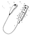
図9〜図12を参照して、サブユニット76について説明する。なお、図9は、サブユニット76の第1の例を示す斜視図である。図10は、図9のサブユニット76の上筐体(ハウジング77の一部)を外した状態を示す斜視図である。図11(a)はサブユニット76の第2の例を示す上面図であり、図11(b)はサブユニット76の第2の例を示す下面図であり、図11(c)はサブユニット76の第2の例を示す左側面図である。図12は、サブユニット76の第2の例を示す上面前方から見た斜視図である。
The
図9において、サブユニット76は、例えばプラスチック成型によって形成されたハウジング77を有している。ハウジング77は、その前後方向を長手方向とし、サブユニット76において最太部となる頭部を前方に形成した流線型の立体形状を有しており、全体として大人や子供の片手で把持可能な大きさである。
In FIG. 9, the
ハウジング77上面の上記最太部近傍に、スティック78aが設けられる。スティック78aは、ハウジング77上面から突出した傾倒可能なスティックを倒すことによって、傾倒方向に応じて操作信号を出力する操作部である。例えば、プレイヤがスティック先端を360°任意の方向に傾倒することによって任意の方向や位置を指定することができ、仮想ゲーム世界に登場するプレイヤキャラクタ等の移動方向を指示したり、カーソルの移動方向を指示したりすることができる。
A
サブユニット76のハウジング77の前面に、複数の操作ボタン78dおよび78eが設けられる。操作ボタン78dおよび78eは、プレイヤがボタン頭部を押下することによって、それぞれの操作ボタン78dおよび78eに割り当てられた操作信号を出力する操作部である。例えば、操作ボタン78dおよび78eには、XボタンおよびYボタン等としての機能が割り当てられる。これら操作ボタン78dおよび78eは、ゲーム装置3が実行するゲームプログラムに応じてそれぞれの機能が割り当てられるが、本発明の説明とは直接関連しないため詳細な説明を省略する。なお、図9に示した配置例では、操作ボタン78dおよび78eは、ハウジング77前面の上下方向に沿って並設されている。
A plurality of
図10において、ハウジング77の内部には基板が固設されており、当該基板の上主面上にスティック78aおよび加速度センサ761等が設けられる。そして、これらは、基板等に形成された配線(図示せず)を介して接続ケーブル79と接続されている。
In FIG. 10, a substrate is fixed inside the
図11および図12において、第2の例のサブユニット76は、第1の例と同様のハウジング77、スティック78a、操作ボタン78dおよび78eを有しており、さらにハウジング77上面に操作ボタン78bおよび78cを設けた態様である。
11 and 12, the
サブユニット76の第2の例では、ハウジング77上面のスティック78aより後面側に、複数の操作ボタン78bおよび78cが設けられる。操作ボタン78bおよび78cは、プレイヤがボタン頭部を押下することによって、それぞれの操作ボタン78bおよび78cに割り当てられた操作信号を出力する操作部である。これら操作ボタン78bおよび78cも、ゲーム装置3が実行するゲームプログラムに応じてそれぞれの機能が割り当てられるが、本発明の説明とは直接関連しないため詳細な説明を省略する。なお、図11および図12に示した配置例では、操作ボタン78bおよび78cは、ハウジング77上面の中央左右方向に沿って並設されている。
In the second example of the
なお、スティック78aは、上述したプレイヤの方向入力操作に応じて操作信号を出力する操作部であるが、他の態様の操作部でもかまわない。以下、図13〜図16を参照して、方向入力操作に応じて操作信号を出力する操作部が第2の例のサブユニット76に設けられた第1〜第5の変形例を説明する。
Note that the
第1の変形例として、図13に示すように、コアユニット70に設けられている十字キー72aと同様の十字キー78fを、上記スティック78aの代わりにサブユニット76に設けてもかまわない。第2の変形例として、図14に示すように、水平移動可能な円盤状部材をスライドさせることによって、当該スライド方向に応じた操作信号を出力するスライドパッド78gを、上記スティック78aの代わりにサブユニット76に設けてもかまわない。第3の変形例として、図15に示すように、タッチパッド78hを、上記スティック78aの代わりにサブユニット76に設けてもかまわない。第4の変形例として、図16に示すように、少なくとも4つの方向(前後左右)をそれぞれ示すボタン78i〜78lを設け、プレイヤによって押下されたボタン78i〜78lに応じて操作信号を出力する操作部を上記スティック78aの代わりにサブユニット76に設けてもかまわない。第5の変形例として、リング状に4方向の操作部分を備えたプッシュスイッチとその中央に設けられたセンタスイッチとを複合した複合スイッチを上記スティック78aの代わりにサブユニット76に設けてもかまわない。
As a first modification, as shown in FIG. 13, a cross key 78f similar to the cross key 72a provided in the
次に、図17を参照して、コントローラ7の内部構成について説明する。なお、図17は、コントローラ7の構成を示すブロック図である。
Next, the internal configuration of the
図17において、コアユニット70は、上述した操作部72、撮像情報演算部74、加速度センサ701、スピーカ706、サウンドIC707、およびアンプ708の他に、その内部に通信部75を備えている。また、サブユニット78は、上述した操作部78および加速度センサ761を備えており、接続ケーブル79とコネクタ791および73とを介して、マイコン751と接続されている。
In FIG. 17, the
撮像情報演算部74は、赤外線フィルタ741、レンズ742、撮像素子743、および画像処理回路744を含んでいる。赤外線フィルタ741は、コアユニット70の前方から入射する光から赤外線のみを通過させる。レンズ742は、赤外線フィルタ741を透過した赤外線を集光して撮像素子743へ出射する。撮像素子743は、例えばCMOSセンサやあるいはCCDのような固体撮像素子であり、レンズ742が集光した赤外線を撮像する。したがって、撮像素子743は、赤外線フィルタ741を通過した赤外線だけを撮像して画像データを生成する。撮像素子743で生成された画像データは、画像処理回路744で処理される。具体的には、画像処理回路744は、撮像素子743から得られた画像データを処理して高輝度部分を検知し、それらの位置座標や面積を検出した結果を示す処理結果データを通信部75へ出力する。なお、これらの撮像情報演算部74は、コアユニット70のハウジング71に固設されており、ハウジング71自体の方向を変えることによってその撮像方向を変更することができる。しかしながら、ハウジング71は、サブユニット76とは屈曲自在な接続ケーブル79によって接続されているため、サブユニット76の方向や位置を変更しても撮像情報演算部74の撮像方向が変化することはない。後述により明らかとなるが、この撮像情報演算部74から出力される処理結果データに基づいて、コアユニット70の位置や動きに応じた信号を得ることができる。
The imaging
コアユニット70は、3軸の加速度センサ701を備えていることが好ましい。また、サブユニット76は、3軸の加速度センサ761を備えていることが好ましい。この3軸の加速度センサ701および761は、それぞれ3方向、すなわち、上下方向、左右方向、および前後方向で直線加速度を検知する。また、他の実施形態においては、ゲーム処理に用いる制御信号の種類によっては、上下および左右方向(または他の対になった方向)のそれぞれに沿った直線加速度のみを検知する2軸の加速度検出手段を使用してもよい。例えば、この3軸または2軸の加速度センサ701および761は、アナログ・デバイセズ株式会社(Analog Devices, Inc.)またはSTマイクロエレクトロニクス社(STMicroelectronics N.V.)から入手可能であるタイプのものでもよい。加速度センサ701および761は、シリコン微細加工されたMEMS(Micro Electro Mechanical Systems:微小電子機械システム)の技術に基づいた静電容量式(静電容量結合式)であることが好ましい。しかしながら、既存の加速度検出手段の技術(例えば、圧電方式や圧電抵抗方式)あるいは将来開発される他の適切な技術を用いて3軸または2軸の加速度センサ701および761が提供されてもよい。
The
当業者には公知であるように、加速度センサ701および761に用いられるような加速度検出手段は、加速度センサの持つ各軸に対応する直線に沿った加速度(直線加速度)のみを検知することができる。つまり、加速度センサ701および761からの直接の出力は、その2軸または3軸のそれぞれに沿った直線加速度(静的または動的)を示す信号である。このため、加速度センサ701および761は、非直線状(例えば、円弧状)の経路に沿った動き、回転、回転運動、角変位、傾斜、位置、または姿勢等の物理特性を直接検知することはできない。
As known to those skilled in the art, the acceleration detection means used in the
しかしながら、加速度センサ701および761からそれぞれ出力される加速度の信号に対して追加の処理を行うことによって、コアユニット70およびサブユニット76に関するさらなる情報をそれぞれ推測または算出することができることは、当業者であれば本明細書の説明から容易に理解できるであろう。例えば、静的な加速度(重力加速度)が検知されると、加速度センサ701および761からの出力を用いて、傾斜角度と検知された加速度とを用いた演算によって重力ベクトルに対する対象(コアユニット70またはサブユニット76)の傾きをそれぞれ推測することができる。このように、加速度センサ701および761をマイコン751(または他のプロセッサ)と組み合わせて用いることによって、コアユニット70およびサブユニット76の傾き、姿勢または位置を決定することができる。同様に、加速度センサ701を備えるコアユニット70または加速度センサ761を備えるサブユニット76が、ここで説明されているように、例えばユーザの手で動的に加速されてそれぞれ動かされる場合に、加速度センサ701および761によって生成される加速度信号をそれぞれ処理することによって、コアユニット70およびサブユニット76のさまざまな動きおよび/または位置をそれぞれ算出または推測することができる。他の実施例では、加速度センサ701および761は、信号をマイコン751に出力する前に内蔵の加速度検出手段から出力される加速度信号に対して所望の処理を行うための、組込み式の信号処理装置または他の種類の専用の処理装置をそれぞれ備えていてもよい。例えば、組込み式または専用の処理装置は、加速度センサが静的な加速度(例えば、重力加速度)を検出するためのものである場合、検知された加速度信号をそれに相当する傾斜角に変換するものであってもよい。加速度センサ701および761でそれぞれ検知された加速度を示すデータは通信部75に出力される。
However, it will be understood by those skilled in the art that additional information regarding the
他の実施形態の例では、加速度センサ701および761の代わりに、少なくとも一方を回転素子または振動素子などを内蔵したジャイロセンサを用いてもよい。この実施形態で使用されるMEMSジャイロセンサの一例として、アナログ・デバイセズ株式会社から入手可能なものがある。加速度センサ701および761と異なり、ジャイロセンサは、それが内蔵する少なくとも一つのジャイロ素子の軸を中心とした回転(または角速度)を直接検知することができる。このように、ジャイロセンサと加速度センサとは基本的に異なるので、個々の用途のためにいずれの装置が選択されるかによって、これらの装置からの出力信号に対して行う処理を適宜変更する必要がある。
In an example of another embodiment, instead of the
具体的には、加速度センサの代わりにジャイロセンサを用いて傾きや姿勢を算出する場合には、大幅な変更を行う。すなわち、ジャイロセンサを用いる場合、検出開始の状態において傾きの値を初期化する。そして、当該ジャイロセンサから出力される角速度データを積分する。次に、初期化された傾きの値からの傾きの変化量を算出する。この場合、算出される傾きは、角度に対応する値が算出されることになる。一方、加速度センサによって傾きを算出する場合には、重力加速度のそれぞれの軸に関する成分の値を、所定の基準と比較することによって傾きを算出するので、算出される傾きはベクトルで表すことが可能であり、初期化を行わずとも、加速度検出手段を用いて検出される絶対的な方向を検出することが可能である。また、傾きとして算出される値の性質は、ジャイロセンサが用いられる場合には角度であるのに対して、加速度センサが用いられる場合にはベクトルであるという違いがある。したがって、加速度センサに代えてジャイロセンサが用いられる場合、当該傾きのデータに対して、2つのデバイスの違いを考慮した所定の変換を行う必要がある。加速度検出手段とジャイロスコープとの基本的な差異と同様にジャイロスコープの特性は当業者に公知であるので、本明細書ではさらなる詳細を省略する。ジャイロセンサは、回転を直接検知できることによる利点を有する一方、一般的には、加速度センサは、本実施形態で用いるようなコントローラに適用される場合、ジャイロセンサに比べて費用効率が良いという利点を有する。 Specifically, when the inclination or posture is calculated using a gyro sensor instead of the acceleration sensor, a significant change is made. That is, when the gyro sensor is used, the inclination value is initialized in the detection start state. Then, the angular velocity data output from the gyro sensor is integrated. Next, a change amount of the inclination from the initialized inclination value is calculated. In this case, the calculated inclination is a value corresponding to the angle. On the other hand, when the inclination is calculated by the acceleration sensor, the inclination is calculated by comparing the value of the component relating to each axis of the gravitational acceleration with a predetermined reference, so the calculated inclination can be expressed by a vector. Thus, it is possible to detect the absolute direction detected using the acceleration detecting means without performing initialization. In addition, the property of the value calculated as the inclination is an angle when a gyro sensor is used, but a vector when an acceleration sensor is used. Therefore, when a gyro sensor is used instead of the acceleration sensor, it is necessary to perform predetermined conversion in consideration of the difference between the two devices with respect to the tilt data. Since the characteristics of the gyroscope as well as the basic differences between the acceleration detection means and the gyroscope are known to those skilled in the art, further details are omitted here. While the gyro sensor has the advantage of being able to directly detect rotation, in general, the acceleration sensor has the advantage of being more cost effective than the gyro sensor when applied to a controller as used in this embodiment. Have.
通信部75は、マイクロコンピュータ(Micro Computer:マイコン)751、メモリ752、無線モジュール753、およびアンテナ754を含んでいる。マイコン751は、処理の際にメモリ752を記憶領域として用いながら、送信データを無線送信する無線モジュール753を制御する。また、マイコン751は、アンテナ754を介して無線モジュール753が受信したゲーム装置3からのデータに応じて、サウンドIC707およびバイブレータ704の動作を制御する。サウンドIC707は、通信部75を介してゲーム装置3から送信されたサウンドデータ等を処理する。
The
コアユニット70に設けられた操作部72からの操作信号(コアキーデータ)、加速度センサ701からの加速度信号(コア加速度データ)、および撮像情報演算部74からの処理結果データは、マイコン751に出力される。また、接続ケーブル79を介して、サブユニット76に設けられた操作部78からの操作信号(サブキーデータ)および加速度センサ761からの加速度信号(サブ加速度データ)は、マイコン751に出力される。マイコン751は、入力した各データ(コアキーデータ、サブキーデータ、コア加速度データ、サブ加速度データ、処理結果データ)を受信ユニット6へ送信する送信データとして一時的にメモリ752に格納する。ここで、通信部75から受信ユニット6への無線送信は、所定の周期毎に行われるが、ゲームの処理は1/60秒を単位として行われることが一般的であるので、それよりも短い周期でデータを収集して送信を行うことが必要となる。具体的には、ゲームの処理単位は16.7ms(1/60秒)であり、ブルートゥース(Bluetooth;登録商標)で構成される通信部75の送信間隔は5msである。マイコン751は、受信ユニット6への送信タイミングが到来すると、メモリ752に格納されている送信データを一連の操作情報として出力し、無線モジュール753へ出力する。そして、無線モジュール753は、例えばブルートゥース(登録商標)の技術に基づいて、所定周波数の搬送波を用いて操作情報で変調し、その微弱電波信号をアンテナ754から放射する。つまり、コアユニット70に設けられた操作部72からのコアキーデータ、サブユニット76に設けられた操作部78からのサブキーデータ、コアユニット70に設けられた加速度センサ701からのコア加速度データ、サブユニット76に設けられた加速度センサ761からのサブ加速度データ、および撮像情報演算部74からの処理結果データは、無線モジュール753で微弱電波信号に変調されてコアユニット70から放射される。そして、ゲーム装置3の受信ユニット6でその微弱電波信号を受信し、ゲーム装置3で当該微弱電波信号を復調や復号することによって、一連の操作情報(コアキーデータ、サブキーデータ、コア加速度データ、サブ加速度データ、および処理結果データ)を取得することができる。そして、ゲーム装置3のCPU30は、取得した操作情報とゲームプログラムとに基づいて、ゲーム処理を行う。なお、Bluetooth(登録商標)の技術を用いて通信部75を構成する場合、通信部75は、他のデバイスから無線送信された送信データを受信する機能も備えることができる。
An operation signal (core key data) from the
図18に示すように、ゲームシステム1でコントローラ7を用いてゲームをプレイするためには、プレイヤは、一方の手(例えば右手)でコアユニット70を把持し(図19および図20参照)、他方の手(例えば左手)でサブユニット76を把持する(図22参照)。そして、プレイヤは、コアユニット70の前面(撮像情報演算部74が撮像する光の入射口側)がモニタ2に向くようにコアユニット70を把持する。一方、モニタ2の表示画面近傍には、2つのLEDモジュール8Lおよび8Rが設置される。これらLEDモジュール8Lおよび8Rは、それぞれモニタ2の前方に向かって赤外光を出力する。
As shown in FIG. 18, in order to play a game using the
プレイヤがその前面がモニタ2に向くようにコアユニット70を把持することによって、撮像情報演算部74には2つのLEDモジュール8Lおよび8Rが出力した赤外光が入射する。そして、赤外線フィルタ741およびレンズ742を介して、入射した赤外光を撮像素子743が撮像し、当該撮像画像を画像処理回路744が処理する。ここで、撮像情報演算部74では、LEDモジュール8Lおよび8Rから出力される赤外線成分を検出することで、当該LEDモジュール8Lおよび8Rの位置や面積情報を取得する。具体的には、撮像情報演算部74は、撮像素子743が撮像した画像データを解析して、面積情報からLEDモジュール8Lおよび8Rからの赤外光ではあり得ない画像を除外し、輝度が高い位置をLEDモジュール8Lおよび8Rそれぞれの位置として判別する。そして、撮像情報演算部74は、判別されたそれらの位置座標やそれらの重心座標等を取得し、上記処理結果データとして出力する。このような処理結果データをゲーム装置3へ送信することによって、ゲーム装置3では、上記位置座標や重心座標に基づいて、LEDモジュール8Lおよび8Rに対する撮像情報演算部74すなわちコアユニット70の動き、姿勢、位置等に関連のある操作信号を得ることができる。具体的には、コアユニット70が動かされることによって、通信部75から送信される画像内の高輝度点の位置が変化するため、高輝度点の位置の変化に対応させた方向入力や座標入力を行うことで、コアユニット70の移動方向に沿った方向入力や座標入力を行うことができる。
When the player holds the
このように、コアユニット70の撮像情報演算部74によって固定的に設置されたマーカ(実施例では、2つのLEDモジュール8Lおよび8Rからの赤外光)を撮像することによって、ゲーム装置3におけるゲーム処理において、コアユニット70の動き、姿勢、位置等に関連した処理結果データを用いることが可能となり、ボタンを押下するような操作ボタンや操作キーとは異なったより直感的な操作入力となる。また、上述したように上記マーカは、モニタ2の表示画面近傍に設置されているため、マーカに対する位置をモニタ2の表示画面に対するコアユニット70の動き、姿勢、位置等に換算することも容易に行うことができる。つまり、コアユニット70の動き、姿勢、位置等による処理結果データは、モニタ2の表示画面に直接作用する操作入力として用いることができる。
As described above, by imaging the marker (in the embodiment, infrared light from the two
図19および図20を参照して、プレイヤがコアユニット70を一方の手で把持した状態について説明する。なお、図19は、プレイヤがコアユニット70を右手で把持した状態をコアユニット70の前面側から見た一例である。図20は、プレイヤがコアユニット70を右手で把持した状態をコアユニット70の左側面側から見た一例である。
A state where the player holds the
図19および図20に示すように、コアユニット70は、全体として大人や子供の片手で把持可能な大きさである。そして、プレイヤの親指をコアユニット70の上面(例えば、十字キー72a付近)に添え、プレイヤの人差し指をコアユニット70下面の凹部(例えば、操作ボタン72i付近)に添えたとき、コアユニット70の前面に設けられている撮像情報演算部74の光入射口がプレイヤの前方方向に露出する。なお、このようなコアユニット70に対する把持状態は、プレイヤの左手であっても同様に行えることは言うまでもない。
As shown in FIGS. 19 and 20, the
このように、コアユニット70は、プレイヤが片手で把持した状態で十字キー72aや操作ボタン72i等の操作部72を容易に操作することができる。さらに、プレイヤがコアユニット70を片手で把持したとき、当該コアユニット70の前面に設けられている撮像情報演算部74の光入射口が露出するため、上述した2つのLEDモジュール8Lおよび8Rからの赤外光を容易に当該光入射口から取り入れることができる。つまり、プレイヤは、撮像情報演算部74の機能を阻害することなくコアユニット70を片手で把持することができる。つまり、プレイヤがコアユニット70を把持した手を表示画面に対して動かすことによって、コアユニット70は、プレイヤの手の運動が表示画面に直接的に作用する操作入力をさらに備えることができる。
In this manner, the
ここで、図21に示すように、LEDモジュール8Lおよび8Rは、それぞれ視野角θ1を有している。また、撮像素子743は、視野角θ2を有している。例えば、LEDモジュール8Lおよび8Rの視野角θ1は共に34°(半値角)であり、撮像素子743の視野角θ2は41°である。そして、撮像素子743の視野角θ2の中にLEDモジュール8Lおよび8Rが共に存在し、LEDモジュール8Lの視野角θ1の中でかつLEDモジュール8Rの視野角θ1の中に撮像素子743が存在するとき、ゲーム装置3は、2つのLEDモジュール8Lおよび8Rによる高輝度点に関する位置データを用いてコアユニット70の位置を判定する。
Here, as shown in FIG. 21, the
一方、撮像素子743の視野角θ2の中に1つのLEDモジュール8Lまたは8Rだけが存在するとき、またはLEDモジュール8Lの視野角θ1およびLEDモジュール8Rの視野角θ1の何れか一方の中に撮像素子743が存在するとき、2つのLEDモジュール8Lおよび8Rの何れか一方だけによる高輝度点に関する位置データを用いてコアユニット70の位置を判定する。
On the other hand, when there is only one
また、上述したようにコアユニット70に設けられた加速度センサ701からの出力(コア加速度データ)を用いることによって、コアユニット70の傾き、姿勢、または位置を決定することができる。つまり、プレイヤがコアユニット70を把持した手を上下左右等に動かすことによって、コアユニット70は、プレイヤの手の運動や向きに応じた操作入力手段として機能する。
Further, by using the output (core acceleration data) from the
次に、図22を参照して、プレイヤがサブユニット76を一方の手で把持した状態について説明する。なお、図22は、プレイヤがサブユニット76を左手で把持した状態をサブユニット76の右側面側から見た一例である。
Next, a state where the player holds the
図22に示すように、サブユニット76は、全体として大人や子供の片手で把持可能な大きさである。例えば、プレイヤの親指をサブユニット76の上面(例えば、スティック78a付近)に添え、プレイヤの人差し指をサブユニット76前面(例えば、操作ボタン78dおよび78e付近)に添え、プレイヤの中指、薬指、および小指をサブユニット76下面に添えるように、サブユニット76を把持することが可能である。なお、このようなサブユニット76に対する把持状態は、プレイヤの右手であっても同様に行えることは言うまでもない。このように、サブユニット76は、プレイヤが片手で把持した状態でスティック78aや操作ボタン78dおよび78e等の操作部78を容易に操作することができる。
As shown in FIG. 22, the
また、上述したようにサブユニット76に設けられた加速度センサ761からの出力(サブ加速度データ)を用いることによって、サブユニット76の傾き、姿勢、または位置を決定することができる。つまり、プレイヤがサブユニット76を把持した手を上下左右等に動かすことによって、サブユニット76は、プレイヤの手の運動や向きに応じた操作入力手段として機能する。
Further, by using the output (sub acceleration data) from the
ここで、上述したコントローラ7を用いてゲーム操作するゲーム例について説明する。第1の例は、コントローラ7を用いてゲーム操作するシューティングゲームである。なお、図23は、ゲーム装置3がシューティングゲームを実行する際にモニタ2に表示されるゲーム画像例を示す図である。
Here, a game example in which a game operation is performed using the
図23において、モニタ2の表示画面には3次元の仮想ゲーム空間Sの一部が表示されている。そして、コントローラ7の操作に応じて動作するゲームオブジェクトとして、表示画面には、プレイヤキャラクタPの一部および当該プレイヤキャラクタPが所持するガンGの一部が表示されている。また、表示画面に表示される仮想ゲーム空間Sは、プレイヤキャラクタSの前方となる視界が表現され、図23の一例では敵キャラクタEがシューティング目標として表示されている。そして、プレイヤキャラクタPがガンGで射撃する位置を表す照準が、照準カーソルTとして表示画面に表示される。
In FIG. 23, a part of the three-dimensional virtual game space S is displayed on the display screen of the monitor 2. As a game object that operates in response to an operation of the
このようなゲーム画像がモニタ2に表示されるシューティングゲームにおいて、プレイヤは、一方の手でコアユニット70を他方の手でサブユニット76を操作して(図18参照)ゲームを進行する。例えば、プレイヤがサブユニット76に設けられたスティック78a(図11、図12参照)を傾倒することによって、当該傾倒方向に応じて仮想ゲーム空間S内をプレイヤキャラクタPが移動する。また、プレイヤがコアユニット70を把持した手を表示画面に対して動かすことによって、当該モニタ2(LEDモジュール8Lおよび8R)に対するコアユニット70の動き、姿勢、位置等に応じて照準カーソルTが移動する。そして、プレイヤがコアユニット70に設けられた操作ボタン72i(図6参照)を押下することによって、プレイヤキャラクタPが所持するガンGが照準カーソルTに向かって射撃する。
In a shooting game in which such a game image is displayed on the monitor 2, the player advances the game by operating the
つまり、プレイヤは、サブユニット76に設けられたスティック78aをプレイヤキャラクタPの移動指示に用いながら、コアユニット70をあたかもシューティングゲームのガンのように用いることができるため、シューティングゲームの興趣が一層増す。そして、プレイヤキャラクタPを移動させる操作と照準カーソルTを移動させる操作とがそれぞれ別の手で把持されたユニットを用いて行われるため、プレイヤの操作動作がそれぞれ独立した思考で行える。例えば、プレイヤキャラクタPの移動に応じて表示画面に表示される仮想ゲーム空間Sが移り変わっていくため、仮想ゲーム空間S内におけるプレイヤが注目する位置付近(例えば、物陰から飛び出してくる敵キャラクタEに注目)に照準を常に位置させることが難しいことがある。しかしながら、一方の手の動作(例えば左手の親指)でプレイヤキャラクタPを移動させながら、コアユニット70の前面を向ける位置が上記注目位置となるように他方の腕の動作(例えば、右腕)で調整できるため、コントローラ7自体の操作の自由度が著しく向上し、臨場感のあるシューティングゲームを実現できる。また、照準カーソルTを移動させるためにコントローラ自体を動かす操作が行われるが、コントローラを動かすことによってプレイヤキャラクタPを移動させる方向指示操作がやりにくくなるというような問題が発生しないため、プレイヤは安定した2つの方向指示操作を行うことができる。つまり、コントローラ7を用いることによって、プレイヤの左右の手が自由になると同時に、物理的に1つのコントローラでは操作できなかった自由度の高い新たな操作が可能になる。
In other words, the player can use the
第2の例は、上記第1の例と同様に、プレイヤがサブユニット76に設けられたスティック78aを傾倒することによって、当該傾倒方向に応じて仮想ゲーム空間S内をプレイヤキャラクタPが移動する。そして、プレイヤがコアユニット70を把持した手を表示画面に対して動かすことによって、当該モニタ2(LEDモジュール8Lおよび8R)に対するコアユニット70の位置に応じて仮想カメラの注視点が移動する。このような操作によって、プレイヤは、サブユニット76に設けられたスティック78aをプレイヤキャラクタPの移動指示に用いながら、コアユニット70を向けた仮想ゲーム空間Sの位置を注視することができる。
In the second example, similar to the first example, when the player tilts the
なお、上述した説明では、コントローラ7とゲーム装置3とが無線通信によって接続された態様を用いたが、コントローラ7とゲーム装置3とがケーブルを介して電気的に接続されてもかまわない。この場合、コアユニット70に接続されたケーブルをゲーム装置3の接続端子に接続する。
In the above description, the
また、コントローラ7を構成するコアユニット70およびサブユニット76のうち、コアユニット70のみに通信部75を設けたが、サブユニット76に受信ユニット6へ送信データを無線送信する通信部を設けてもかまわない。また、コアユニット70およびサブユニット76それぞれに上記通信部を設けてもかまわない。例えば、コアユニット70およびサブユニット76に設けられた通信部がそれぞれ受信ユニット6へ送信データを無線送信してもいいし、サブユニット76の通信部からコアユニット70へ送信データを無線送信してコアユニット70の通信部75で受信した後、コアユニット70の通信部75がサブユニット76の送信データと共にコアユニット70の送信データを受信ユニット6へ無線送信してもいい。これらの場合、コアユニット70とサブユニット76とを電気的に接続する接続ケーブル79が不要となる。
Further, although the
また、コントローラ7から無線送信される送信データを受信する受信手段として、ゲーム装置3の接続端子に接続された受信ユニット6を用いて説明したが、ゲーム装置3の本体内部に設けられた受信モジュールによって当該受信手段を構成してもかまわない。この場合、受信モジュールが受信した送信データは、所定のバスを介してCPU30に出力される。
Further, the reception unit 6 connected to the connection terminal of the game apparatus 3 has been described as the reception means for receiving transmission data wirelessly transmitted from the
また、コアユニット70本体の動きに応じて変化する信号(処理結果データ)を出力する判定部の一例として、撮像情報演算部74をコアユニット70に内蔵して説明したが、他の機構でもかまわない。例えば、コアユニット70は、上述したように加速度センサ701を内蔵しており、ジャイロセンサが用いられていることもあり得る。加速度センサやジャイロセンサは、コアユニット70の動きや姿勢の判定に用いられることが可能であり、その結果、これらの検出信号を用いればコアユニット70本体の動きに応じて変化する信号を出力する判定部のように用いることができる。この場合、コアユニット70に内蔵された撮像情報演算部74を排除してもよいし、センサと撮像情報演算部の両者を組み合わせる構成としてもよい。
In addition, as an example of a determination unit that outputs a signal (processing result data) that changes according to the movement of the
また、撮像情報演算部74をコアユニット70のみに設けたが、サブユニット76にも同様の撮像情報演算部を設けてもかまわない。
Further, although the imaging
また、コントローラ7は、複数のユニットで構成され、それぞれ複数の操作手段(撮像情報演算部、加速度センサ、ジャイロセンサ、スティック、十字キー、操作ボタン等)を設けることができるために、それらの組み合わせによって様々なコントローラが実現する。ここで、コアユニット70およびサブユニット76にそれぞれ設けられる操作手段を、ユニット本体の動きに応じた信号を出力する操作手段A(例えば、撮像情報演算部74、加速度センサ701および761、ジャイロセンサ)と、プレイヤがボタンを押下したり部材を傾倒させたりタッチしたりすることに応じた信号を出力する操作手段B(例えば、スティック、十字キー、操作ボタン、タッチパッド等)とに分類して説明する。
Further, since the
コアユニット70に操作手段Aを設け、サブユニット76に操作手段Bを設けた場合、プレイヤが一方の手にコアユニット70を把持して手自体を動かし、他方の手にサブユニット76を把持して従来のコントローラと同じように指による入力を行うことができる。つまり、プレイヤの左右の手で全く異なる操作をさせることが可能になるので、従来にない新たな操作が可能となる。この場合、本発明では、操作手段Aから出力される操作データが第1操作データに相当し、操作手段Bから出力される操作データが第2操作データに相当する。さらに、サブユニット76に操作手段Aを設けて、コアユニット70に操作手段Aを設け、サブユニット76に操作手段Aおよび操作手段Bを設ける態様もある。この態様では、プレイヤが両方の手自体をそれぞれ動かす操作も可能となり、さらに新たな操作が可能となる。この場合、本発明では、サブユニット76の操作手段Aから出力される操作データが第3操作データに相当する。
When the operating unit A is provided in the
また、コアユニット70およびサブユニット76それぞれに操作手段Aを設けた場合、プレイヤが一方の手にコアユニット70を把持して手自体を動かし、他方の手もサブユニット76を把持して手自体を動かして操作するような入力を行うことができる。つまり、プレイヤの左右の手をそれぞれ動かす操作をさせることが可能になるので、従来にない新たな操作が可能となる。この場合、本発明では、操作手段Aから出力されるそれぞれの操作データが第1操作データおよび第2操作データに相当する。さらに、コアユニット70およびサブユニット76にそれぞれ操作手段AおよびBを設ける態様もある。この態様では、プレイヤが両方の手自体を動かす操作および両手の指による操作をそれぞれ行うことができ、さらに新たな操作が可能となる。この場合、本発明では、コアユニット70の操作手段Bから出力される操作データが第1のキー操作データに相当し、サブユニット76の操作手段Bから出力される操作データが第2のキー操作データに相当する。
When the operating means A is provided in each of the
さらに、コアユニット70およびサブユニット76それぞれに操作手段Aを設けた場合、複数種類の操作手段Aを一方のユニットに設ける態様も考えられる。上述したように、操作手段Aを撮像情報演算部で構成した場合、撮像対象(マーカ)に対するユニットの方向や位置等を算出できるため、モニタ2に対するユニット方向や位置に応じた操作が可能となる。一方、操作手段Aを加速度センサやジャイロセンサで構成した場合、ユニット自体の傾き、姿勢、および位置等を算出することができるため、ユニットの姿勢や位置に応じた操作が可能となる。したがって、コアユニット70に撮像情報演算部と加速度センサまたはジャイロセンサとを設け、サブユニット76に加速度センサまたはジャイロセンサとを設けることによって、コアユニット70では上述した両者の操作が1つのユニットで可能となる。この場合、本発明では、コアユニット70の撮像情報演算部から出力される操作データが第1操作データに相当し、サブユニット76の加速度センサまたはジャイロセンサから出力される操作データが第2操作データに相当し、コアユニット70の加速度センサまたはジャイロセンサから出力される操作データが第3操作データに相当する。
Furthermore, when the operation means A is provided in each of the
また、撮像素子743で撮像した画像データを解析してLEDモジュール8Lおよび8Rからの赤外光の画像の位置座標等を取得し、それらを処理結果データとしてコアユニット70内で生成してゲーム装置3へ送信する態様を説明したが、他の処理段階のデータをコアユニット70からゲーム装置3へ送信してもかまわない。例えば、撮像素子743が撮像した画像データをコアユニット70からゲーム装置3へ送信し、CPU30において上記解析処理を行って処理結果データを取得してもかまわない。この場合、コアユニット70に設けられた画像処理回路744が不要となる。また、上記画像データの解析途中のデータをコアユニット70からゲーム装置3へ送信してもかまわない。例えば、画像データから得られる輝度、位置、および面積等を示すデータをコアユニット70からゲーム装置3へ送信し、CPU30において残りの解析処理を行って処理結果データを取得してもかまわない。
Further, the image data picked up by the
また、上述した説明では、2つのLEDモジュール8Lおよび8Rからの赤外光を、コアユニット70の撮像情報演算部74の撮像対象としたが、他のものを撮像対象にしてもかまわない。例えば、1つまたは3つ以上のLEDモジュールをモニタ2の近傍に設置し、それらのLEDモジュールからの赤外光を撮像情報演算部74の撮像対象としてもかまわない。また、モニタ2の表示画面自体や他の発光体(室内灯等)を撮像情報演算部74の撮像対象としてもかまわない。撮像対象とモニタ2の表示画面との配置関係に基づいて、当該表示画面に対するコアユニット70の位置を演算すれば、様々な発光体を撮像情報演算部74の撮像対象として用いることができる。
Further, in the above description, the infrared light from the two
また、上述したコアユニット70およびサブユニット76の形状や、それらに設けられている操作部72および78の形状、数、および設置位置等は、単なる一例に過ぎず他の形状、数、および設置位置であっても、本発明を実現できることは言うまでもない。また、コアユニット70における撮像情報演算部74の位置(撮像情報演算部74の光入射口)は、ハウジング71の前面でなくてもよく、ハウジング71の外部から光を取り入れることができれば他の面に設けられてもかまわない。
Further, the shapes of the
また、上述したスピーカ706、サウンドIC707、アンプ708は、コアユニット70側に設けられたが、手元で音声を発生するものであればよく、サブユニット76側に設けられていてもかまわない。
Further, although the above-described
このように、本発明のコントローラは、コアユニット70およびサブユニット76を共に操作に用いて、ゲームを楽しむことができる。ここで、一例として、コアユニット70は、撮像情報演算部74や加速度センサ701等のユニット本体の動きに応じた信号を出力する機能を有しており、サブユニット76は、プレイヤの方向入力操作に応じた信号を出力する機能を有している。例えば、コアユニット70とサブユニット76とが合体して一体となったコントローラを仮定した場合、ユニット本体の動きに応じた信号を出力するためには全体を動かすことが必要となり、方向入力操作に影響を与えてしまう。また、その逆の影響も生じてしまう。つまり、コアユニット70とサブユニット76とを合体させると、分離することにより実現していた自由度が著しく損なわれてしまう。また、他の例として、コアユニット70は、撮像情報演算部74や加速度センサ701等のユニット本体の動きに応じた信号を出力する機能を有しており、サブユニット76も、加速度センサ761等のユニット本体の動きに応じた信号を出力する機能を有している。これによって、プレイヤが両方の手に別々のユニットを把持してそれぞれの手自体を動かして操作するような入力を行うことができる。したがって、コアユニット70およびサブユニット76は、従来のゲーム機用コントローラを単に左右に分離できるように構成しただけでなく、プレイヤの左右の手が自由になると同時に合体型では操作できなかった新たな操作が可能となっている。また、コントローラ自体の操作の自由度が著しく向上しているため、臨場感のあるゲーム操作を実現できる。
Thus, the controller of the present invention can enjoy the game by using both the
本発明に係るゲームコントローラおよびゲームシステムは、自由度の高い操作を実現することができ、1人のプレイヤが物理的に分離した2つのユニットを把持して操作するゲームコントローラおよびゲームシステム等として有用である。 INDUSTRIAL APPLICABILITY The game controller and game system according to the present invention can realize highly flexible operations, and are useful as game controllers and game systems in which one player holds and operates two physically separated units. It is.
1…ゲームシステム
2…モニタ
2b…スピーカ
3…ゲーム装置
30…CPU
31…メモリコントローラ
32…GPU
33…メインメモリ
34…DSP
35…ARAM
36…コントローラI/F
37…ビデオI/F
38…外部メモリI/F
39…オーディオI/F
40…ディスクドライブ
41…ディスクI/F
4…光ディスク
5…外部メモリカード
6…受信ユニット
7…コントローラ
70…コアユニット
71、77…ハウジング
72、78…操作部
73、791…コネクタ
74…撮像情報演算部
741…赤外線フィルタ
742…レンズ
743…撮像素子
744…画像処理回路
75…通信部
751…マイコン
752…メモリ
753…無線モジュール
754…アンテナ
700…基板
701、761…加速度センサ
702…LED
703…水晶振動子
704…バイブレータ
706…スピーカ
707…サウンドIC
708…アンプ
76…サブユニット
79…接続ケーブル
8…LEDモジュール
DESCRIPTION OF
31 ... Memory controller 32 ... GPU
33 ...
35 ... ARAM
36 ... Controller I / F
37 ... Video I / F
38 ... External memory I / F
39 ... Audio I / F
40 ...
4 ...
703 ...
708 ...
Claims (8)
第1のコントロールユニットと、
第2のコントロールユニットと、
前記第1のコントロールユニットと前記第2のコントロールユニットとを電気的に接続しかつ屈曲自在なケーブルとを備え、
前記第1のコントロールユニットは、前記第1のコントロールユニット本体に固設され、前記第1のコントロールユニット本体を基準に所定方向の周辺を撮像する撮像部を含み、当該撮像部によって撮像した撮像画像自体または撮像画像に所定の演算を行った結果を少なくとも含む第1操作データを出力する第1操作データ発生部を含み、
前記第2のコントロールユニットは、前記第2のコントロールユニット本体に設けられた第1の加速度センサまたは第1のジャイロセンサを含み、当該第1の加速度センサまたは第1のジャイロセンサから発生したデータを少なくとも含む第2操作データを出力する第2操作データ発生部を含み、
さらに、前記第1のコントロールユニットまたは前記第2のコントロールユニットは、所定のタイミングで前記第1操作データおよび前記第2操作データを前記コンピュータに送信する送信部を含む、ゲームコントローラ。 A game controller for transmitting operation data to a computer executing a game program,
A first control unit;
A second control unit;
A cable that electrically connects the first control unit and the second control unit and is bendable;
The first control unit is fixed to the first control unit main body, includes an imaging unit that images a periphery in a predetermined direction with reference to the first control unit main body, and a captured image captured by the imaging unit A first operation data generation unit that outputs first operation data including at least a result of performing a predetermined calculation on itself or a captured image ;
The second control unit includes a first acceleration sensor or a first gyro sensor provided in the second control unit main body, and generates data generated from the first acceleration sensor or the first gyro sensor. Including a second operation data generation unit for outputting at least second operation data including,
Furthermore, the first control unit or the second control unit includes a transmission unit that transmits the first operation data and the second operation data to the computer at a predetermined timing.
第1のコントロールユニットと、A first control unit;
第2のコントロールユニットと、A second control unit;
前記第1のコントロールユニットと前記第2のコントロールユニット間を無線接続する無線接続手段とを備え、Wireless connection means for wirelessly connecting between the first control unit and the second control unit;
前記第1のコントロールユニットは、前記第1のコントロールユニット本体に固設され、前記第1のコントロールユニット本体を基準に所定方向の周辺を撮像する撮像部を含み、当該撮像部によって撮像した撮像画像自体または撮像画像に所定の演算を行った結果を少なくとも含む第1操作データを出力する第1操作データ発生部を含み、The first control unit is fixed to the first control unit main body, includes an imaging unit that images a periphery in a predetermined direction with reference to the first control unit main body, and a captured image captured by the imaging unit A first operation data generation unit that outputs first operation data including at least a result of performing a predetermined calculation on itself or a captured image;
前記第2のコントロールユニットは、前記第2のコントロールユニット本体に設けられた第1の加速度センサまたは第1のジャイロセンサを含み、当該第1の加速度センサまたは第1のジャイロセンサから発生したデータを少なくとも含む第2操作データを出力する第2操作データ発生部を含み、The second control unit includes a first acceleration sensor or a first gyro sensor provided in the second control unit main body, and generates data generated from the first acceleration sensor or the first gyro sensor. Including a second operation data generation unit for outputting at least second operation data including,
さらに、前記第1のコントロールユニットまたは前記第2のコントロールユニットは、所定のタイミングで前記第1操作データおよび前記第2操作データを前記コンピュータに送信する送信部を含む、ゲームコントローラ。Furthermore, the first control unit or the second control unit includes a transmission unit that transmits the first operation data and the second operation data to the computer at a predetermined timing.
前記第2のコントロールユニットは、当該第2のコントロールユニット本体に設けられ、プレイヤが押下することに応じた第2のキー操作データを発生する第2のキーを、さらに含み、
前記送信部は、前記第1操作データおよび前記第2操作データとともに、前記第1のキー操作データおよび前記第2のキー操作データを前記コンピュータに送信する、請求項3に記載のゲームコントローラ。 The first control unit further includes a first key that is provided in the first control unit main body and that generates first key operation data in response to pressing by the player;
The second control unit further includes a second key that is provided in the second control unit main body and generates second key operation data in response to pressing by the player,
The game controller according to claim 3 , wherein the transmission unit transmits the first key operation data and the second key operation data together with the first operation data and the second operation data to the computer.
スピーカと、
前記受信部が受信した送信データに基づいて、前記スピーカから音声を発生させる音声制御部とを含む、請求項1乃至4の何れかに記載のゲームコントローラ。 Further, at least one of the first control unit and the second control unit includes a receiving unit that receives transmission data transmitted from the computer side,
Speakers,
On the basis of the transmission data received by the receiver, and a sound controller for generating sound from the speaker, game controller according to any one of claims 1 to 4.
前記ゲーム装置は、前記コントロールユニットから送信される操作データに応じてゲーム処理を行うことを特徴とする、ゲームシステム。 A game system comprising: the game controller according to any one of claims 1 to 5 ; and a game device including a computer connected to the game controller so as to be communicable and executing a game program to express a virtual game world on a display screen. Because
The game system performs game processing in accordance with operation data transmitted from the control unit.
第1のコントロールユニットと、A first control unit;
第2のコントロールユニットと、A second control unit;
前記第1のコントロールユニットと前記第2のコントロールユニットとを電気的に接続する接続部を備え、A connecting portion for electrically connecting the first control unit and the second control unit;
前記第1のコントロールユニットは、前記第1のコントロールユニット本体に固設され、前記第1のコントロールユニット本体を基準に所定方向の周辺を撮像する撮像部と、前記第1のコントロールユニット本体に設けられた第1の加速度センサまたは第1のジャイロセンサとを含み、前記撮像部によって撮像した撮像画像自体または撮像画像に所定の演算を行った結果と、前記第1の加速度センサまたは第1のジャイロセンサから発生したデータとを少なくとも含む第1操作データを出力する第1操作データ発生部を含み、The first control unit is fixed to the first control unit main body, and is provided in the first control unit main body, and an image pickup unit that picks up a periphery in a predetermined direction with reference to the first control unit main body. The first acceleration sensor or the first gyro sensor, and a result obtained by performing a predetermined calculation on the captured image itself or the captured image captured by the imaging unit, and the first acceleration sensor or the first gyro sensor. A first operation data generating unit that outputs first operation data including at least data generated from the sensor;
前記第2のコントロールユニットは、前記第2のコントロールユニット本体に設けられた第2の加速度センサまたは第2のジャイロセンサを含み、前記第2の加速度センサまたは第2のジャイロセンサから発生したデータを少なくとも含む第2操作データを出力する第2操作データ発生部を含み、The second control unit includes a second acceleration sensor or a second gyro sensor provided in the second control unit main body, and generates data generated from the second acceleration sensor or the second gyro sensor. Including a second operation data generation unit for outputting at least second operation data including,
さらに、前記第1のコントロールユニットまたは前記第2のコントロールユニットは、所定のタイミングで前記第1操作データおよび前記第2操作データを前記コンピュータに送信する送信部を含む、ゲームコントローラ。Furthermore, the first control unit or the second control unit includes a transmission unit that transmits the first operation data and the second operation data to the computer at a predetermined timing.
Priority Applications (16)
| Application Number | Priority Date | Filing Date | Title |
|---|---|---|---|
| JP2006122681A JP4262726B2 (en) | 2005-08-24 | 2006-04-26 | Game controller and game system |
| EP20100178309 EP2292305B1 (en) | 2005-08-24 | 2006-08-11 | Video game controller and video game system |
| EP06016810.1A EP1757345B1 (en) | 2005-08-24 | 2006-08-11 | Video game controller and video game system |
| ES10178309.0T ES2527047T3 (en) | 2005-08-24 | 2006-08-11 | Video game controller and video game system |
| ES06016810T ES2711609T3 (en) | 2005-08-24 | 2006-08-11 | Video game controller and video game system |
| DE200620020820 DE202006020820U1 (en) | 2005-08-24 | 2006-08-11 | Game controller and game system |
| US11/504,086 US8267786B2 (en) | 2005-08-24 | 2006-08-15 | Game controller and game system |
| CN2006101115597A CN1919390B (en) | 2005-08-24 | 2006-08-23 | Video game controller and video game system |
| CN201010112165XA CN101837191B (en) | 2005-08-24 | 2006-08-23 | Game controller and game system |
| KR20060079817A KR101231989B1 (en) | 2005-08-24 | 2006-08-23 | Game controller and game system |
| US12/285,812 US8834271B2 (en) | 2005-08-24 | 2008-10-15 | Game controller and game system |
| US14/330,403 US9044671B2 (en) | 2005-08-24 | 2014-07-14 | Game controller and game system |
| US14/585,318 US9227138B2 (en) | 2005-08-24 | 2014-12-30 | Game controller and game system |
| US14/950,578 US9498709B2 (en) | 2005-08-24 | 2015-11-24 | Game controller and game system |
| US15/295,290 US10137365B2 (en) | 2005-08-24 | 2016-10-17 | Game controller and game system |
| US16/161,745 US11027190B2 (en) | 2005-08-24 | 2018-10-16 | Game controller and game system |
Applications Claiming Priority (2)
| Application Number | Priority Date | Filing Date | Title |
|---|---|---|---|
| JP2005242926 | 2005-08-24 | ||
| JP2006122681A JP4262726B2 (en) | 2005-08-24 | 2006-04-26 | Game controller and game system |
Related Child Applications (3)
| Application Number | Title | Priority Date | Filing Date |
|---|---|---|---|
| JP2007203785A Division JP4240510B2 (en) | 2005-08-24 | 2007-08-06 | Game controller and game system |
| JP2008256858A Division JP2009064449A (en) | 2005-08-24 | 2008-10-01 | Controller and computer system |
| JP2008274709A Division JP5074346B2 (en) | 2005-08-24 | 2008-10-24 | Game controller and game system |
Publications (3)
| Publication Number | Publication Date |
|---|---|
| JP2007083013A JP2007083013A (en) | 2007-04-05 |
| JP2007083013A5 JP2007083013A5 (en) | 2007-09-20 |
| JP4262726B2 true JP4262726B2 (en) | 2009-05-13 |
Family
ID=37036875
Family Applications (1)
| Application Number | Title | Priority Date | Filing Date |
|---|---|---|---|
| JP2006122681A Active JP4262726B2 (en) | 2005-08-24 | 2006-04-26 | Game controller and game system |
Country Status (7)
| Country | Link |
|---|---|
| US (7) | US8267786B2 (en) |
| EP (2) | EP1757345B1 (en) |
| JP (1) | JP4262726B2 (en) |
| KR (1) | KR101231989B1 (en) |
| CN (1) | CN101837191B (en) |
| DE (1) | DE202006020820U1 (en) |
| ES (2) | ES2527047T3 (en) |
Families Citing this family (145)
| Publication number | Priority date | Publication date | Assignee | Title |
|---|---|---|---|---|
| US7749089B1 (en) | 1999-02-26 | 2010-07-06 | Creative Kingdoms, Llc | Multi-media interactive play system |
| US7878905B2 (en) | 2000-02-22 | 2011-02-01 | Creative Kingdoms, Llc | Multi-layered interactive play experience |
| US7445550B2 (en) | 2000-02-22 | 2008-11-04 | Creative Kingdoms, Llc | Magical wand and interactive play experience |
| US6761637B2 (en) | 2000-02-22 | 2004-07-13 | Creative Kingdoms, Llc | Method of game play using RFID tracking device |
| US7066781B2 (en) | 2000-10-20 | 2006-06-27 | Denise Chapman Weston | Children's toy with wireless tag/transponder |
| US6990639B2 (en) | 2002-02-07 | 2006-01-24 | Microsoft Corporation | System and process for controlling electronic components in a ubiquitous computing environment using multimodal integration |
| US20070066396A1 (en) | 2002-04-05 | 2007-03-22 | Denise Chapman Weston | Retail methods for providing an interactive product to a consumer |
| US6967566B2 (en) | 2002-04-05 | 2005-11-22 | Creative Kingdoms, Llc | Live-action interactive adventure game |
| US7033176B2 (en) * | 2002-07-17 | 2006-04-25 | Powergrid Fitness, Inc. | Motion platform system and method of rotating a motion platform about plural axes |
| US7674184B2 (en) | 2002-08-01 | 2010-03-09 | Creative Kingdoms, Llc | Interactive water attraction and quest game |
| US20070155589A1 (en) * | 2002-12-04 | 2007-07-05 | Philip Feldman | Method and Apparatus for Operatively Controlling a Virtual Reality Scenario with an Isometric Exercise System |
| US7699755B2 (en) | 2002-12-04 | 2010-04-20 | Ialabs-Ca, Llc | Isometric exercise system and method of facilitating user exercise during video game play |
| US7727117B2 (en) | 2002-12-04 | 2010-06-01 | Ialabs-Ca, Llc | Method and apparatus for operatively controlling a virtual reality scenario with a physically demanding interface |
| US8745541B2 (en) * | 2003-03-25 | 2014-06-03 | Microsoft Corporation | Architecture for controlling a computer using hand gestures |
| US9446319B2 (en) | 2003-03-25 | 2016-09-20 | Mq Gaming, Llc | Interactive gaming toy |
| US7665041B2 (en) | 2003-03-25 | 2010-02-16 | Microsoft Corporation | Architecture for controlling a computer using hand gestures |
| US9573056B2 (en) * | 2005-10-26 | 2017-02-21 | Sony Interactive Entertainment Inc. | Expandable control device via hardware attachment |
| US8629836B2 (en) | 2004-04-30 | 2014-01-14 | Hillcrest Laboratories, Inc. | 3D pointing devices with orientation compensation and improved usability |
| JP2007535773A (en) | 2004-04-30 | 2007-12-06 | ヒルクレスト・ラボラトリーズ・インコーポレイテッド | Free space pointing device and pointing method |
| US8137195B2 (en) | 2004-11-23 | 2012-03-20 | Hillcrest Laboratories, Inc. | Semantic gaming and application transformation |
| US7492367B2 (en) * | 2005-03-10 | 2009-02-17 | Motus Corporation | Apparatus, system and method for interpreting and reproducing physical motion |
| US7942745B2 (en) * | 2005-08-22 | 2011-05-17 | Nintendo Co., Ltd. | Game operating device |
| US7927216B2 (en) | 2005-09-15 | 2011-04-19 | Nintendo Co., Ltd. | Video game system with wireless modular handheld controller |
| US8313379B2 (en) | 2005-08-22 | 2012-11-20 | Nintendo Co., Ltd. | Video game system with wireless modular handheld controller |
| JP4805633B2 (en) | 2005-08-22 | 2011-11-02 | 任天堂株式会社 | Game operation device |
| JP4262726B2 (en) | 2005-08-24 | 2009-05-13 | 任天堂株式会社 | Game controller and game system |
| US8870655B2 (en) | 2005-08-24 | 2014-10-28 | Nintendo Co., Ltd. | Wireless game controllers |
| US8308563B2 (en) | 2005-08-30 | 2012-11-13 | Nintendo Co., Ltd. | Game system and storage medium having game program stored thereon |
| US8157651B2 (en) | 2005-09-12 | 2012-04-17 | Nintendo Co., Ltd. | Information processing program |
| JP4151982B2 (en) * | 2006-03-10 | 2008-09-17 | 任天堂株式会社 | Motion discrimination device and motion discrimination program |
| JP4684147B2 (en) * | 2006-03-28 | 2011-05-18 | 任天堂株式会社 | Inclination calculation device, inclination calculation program, game device, and game program |
| US9364755B1 (en) | 2006-05-08 | 2016-06-14 | Nintendo Co., Ltd. | Methods and apparatus for using illumination marks for spatial pointing |
| JP4989105B2 (en) * | 2006-05-09 | 2012-08-01 | 任天堂株式会社 | Game controller |
| US9405372B2 (en) | 2006-07-14 | 2016-08-02 | Ailive, Inc. | Self-contained inertial navigation system for interactive control using movable controllers |
| JP5051822B2 (en) | 2006-08-02 | 2012-10-17 | 任天堂株式会社 | Game device with general-purpose remote control function |
| US20090017910A1 (en) * | 2007-06-22 | 2009-01-15 | Broadcom Corporation | Position and motion tracking of an object |
| US20100184499A1 (en) * | 2007-02-01 | 2010-07-22 | Ritter Janice E | Electronic Game Device and Method of Using the Same |
| US20080188277A1 (en) * | 2007-02-01 | 2008-08-07 | Ritter Janice E | Electronic Game Device And Method Of Using The Same |
| US10504317B2 (en) * | 2007-04-30 | 2019-12-10 | Cfph, Llc | Game with player actuated control structure |
| US8100769B2 (en) | 2007-05-09 | 2012-01-24 | Nintendo Co., Ltd. | System and method for using accelerometer outputs to control an object rotating on a display |
| US8147333B2 (en) | 2007-05-09 | 2012-04-03 | Nintendo Co. Ltd. | Handheld control device for a processor-controlled system |
| US9317110B2 (en) | 2007-05-29 | 2016-04-19 | Cfph, Llc | Game with hand motion control |
| US20080309618A1 (en) * | 2007-06-12 | 2008-12-18 | Kazuyuki Okada | Methods and systems for controlling an input device, for generating collision data, and for controlling a camera angle |
| TW200900123A (en) * | 2007-06-18 | 2009-01-01 | Ailive Inc | Self-contained inertial navigation system for interactive control using movable controllers |
| JP4916390B2 (en) * | 2007-06-20 | 2012-04-11 | 任天堂株式会社 | Information processing program, information processing apparatus, information processing system, and information processing method |
| US20100292007A1 (en) * | 2007-06-26 | 2010-11-18 | Nintendo Of America Inc. | Systems and methods for control device including a movement detector |
| EP2014341B8 (en) | 2007-07-09 | 2017-08-30 | Sony Interactive Entertainment Inc. | Game Controller |
| JP5210568B2 (en) * | 2007-08-06 | 2013-06-12 | 株式会社タイトー | game machine |
| TWI337320B (en) * | 2007-08-10 | 2011-02-11 | Ind Tech Res Inst | An input control apparatus and an interactive system using the same |
| TWI333156B (en) * | 2007-08-16 | 2010-11-11 | Ind Tech Res Inst | Inertia sensing input controller and receiver and interactive system using thereof |
| JP5224748B2 (en) * | 2007-08-27 | 2013-07-03 | 任天堂株式会社 | Information processing apparatus, information processing system, information processing program, and information processing method |
| TWI362605B (en) * | 2007-08-30 | 2012-04-21 | Ind Tech Res Inst | Method for adjusting sensing range and sensitivity and inertia interactive apparatus and system using thereof |
| JP2009072319A (en) * | 2007-09-19 | 2009-04-09 | Namco Bandai Games Inc | Program, information memory medium, game device and controller |
| JP5349785B2 (en) | 2007-10-26 | 2013-11-20 | 株式会社バンダイナムコゲームス | Operation tool |
| KR100947735B1 (en) * | 2008-01-04 | 2010-03-17 | 에스케이 텔레콤주식회사 | System and method for controlling motion in virtual reality enviroment |
| JP5224832B2 (en) * | 2008-01-21 | 2013-07-03 | 任天堂株式会社 | Information processing program and information processing apparatus |
| JP5429918B2 (en) * | 2008-02-15 | 2014-02-26 | 任天堂株式会社 | Information processing program and information processing apparatus |
| TW200951762A (en) * | 2008-06-03 | 2009-12-16 | Asustek Comp Inc | Input device and operation method of computer |
| JP4773492B2 (en) | 2008-09-12 | 2011-09-14 | 任天堂株式会社 | GAME DEVICE AND GAME PROGRAM |
| US8284170B2 (en) | 2008-09-30 | 2012-10-09 | Apple Inc. | Touch screen device, method, and graphical user interface for moving on-screen objects without using a cursor |
| JP5358152B2 (en) | 2008-10-03 | 2013-12-04 | 任天堂株式会社 | Handheld information processing device |
| JP5582629B2 (en) * | 2008-10-16 | 2014-09-03 | 任天堂株式会社 | Information processing apparatus and information processing program |
| JP5538706B2 (en) * | 2008-11-14 | 2014-07-02 | 株式会社ソニー・コンピュータエンタテインメント | Operation device |
| US8747224B2 (en) | 2008-11-14 | 2014-06-10 | Sony Corporation | Operating device |
| JP5113775B2 (en) * | 2009-01-29 | 2013-01-09 | 株式会社コナミデジタルエンタテインメント | GAME DEVICE, OPERATION EVALUATION METHOD, AND PROGRAM |
| US8517835B2 (en) * | 2009-02-20 | 2013-08-27 | Activision Publishing, Inc. | Video game and peripheral for same |
| JP2010233742A (en) * | 2009-03-30 | 2010-10-21 | Konami Digital Entertainment Co Ltd | Game device, operation determination method, and program |
| JP5522349B2 (en) * | 2009-04-14 | 2014-06-18 | 任天堂株式会社 | INPUT SYSTEM, INFORMATION PROCESSING SYSTEM, PERIPHERAL DEVICE CONTROL METHOD, AND OPERATION DEVICE CONTROL PROGRAM |
| US9352218B2 (en) * | 2009-04-21 | 2016-05-31 | Nintendo Co., Ltd. | Game apparatus and computer-readable storage medium |
| TW201043311A (en) * | 2009-06-08 | 2010-12-16 | Pixart Imaging Inc | Two-dimensional input device, control device and interactive game system |
| EP2327460B1 (en) * | 2009-07-24 | 2022-01-12 | Nintendo Co., Ltd. | Game system and controller |
| JP5651324B2 (en) * | 2009-11-11 | 2015-01-07 | 任天堂株式会社 | GAME PROGRAM, GAME DEVICE, AND GAME CONTROL METHOD |
| US9101831B2 (en) * | 2009-11-24 | 2015-08-11 | Activision Publishing, Inc. | Video game and peripheral for same |
| JP5306455B2 (en) * | 2010-03-30 | 2013-10-02 | 株式会社カプコン | Program, object control method, recording medium, and game system |
| JP2010201180A (en) * | 2010-04-30 | 2010-09-16 | Nintendo Co Ltd | Game apparatus and game program |
| KR101068799B1 (en) * | 2010-10-18 | 2011-10-04 | 손영식 | Controller being used in apparatus for screen shooting and driving method thereof |
| AU2011318246A1 (en) | 2010-10-22 | 2013-05-09 | Joshua Michael Young | Methods devices and systems for creating control signals |
| US8605048B2 (en) | 2010-11-05 | 2013-12-10 | Bluespace Corporation | Method and apparatus for controlling multimedia contents in realtime fashion |
| KR101388673B1 (en) * | 2010-11-12 | 2014-04-25 | 도시바삼성스토리지테크놀러지코리아 주식회사 | Game controller, game machine, and game system employ the game controller |
| KR101339431B1 (en) * | 2010-11-19 | 2013-12-09 | 도시바삼성스토리지테크놀러지코리아 주식회사 | Game controller, game machine, and game system employ the game controller |
| CN102479548A (en) * | 2010-11-24 | 2012-05-30 | 浩一科技有限公司 | Data writing method and writing device of electrically erasable programmable read-only memory |
| US9140590B2 (en) * | 2011-02-09 | 2015-09-22 | Texas Instruments Incorporated | System and method of power-saving in MEMS sensor applications |
| KR20130037801A (en) * | 2011-10-07 | 2013-04-17 | 삼성전자주식회사 | Remote control apparatus, remote control method and display apparatus |
| US8811938B2 (en) | 2011-12-16 | 2014-08-19 | Microsoft Corporation | Providing a user interface experience based on inferred vehicle state |
| US9690392B2 (en) * | 2012-10-15 | 2017-06-27 | Sony Corporation | Operating device including a touch sensor |
| KR102249208B1 (en) | 2012-10-15 | 2021-05-10 | 주식회사 소니 인터랙티브 엔터테인먼트 | Control deⅵce |
| JP2013175208A (en) * | 2013-04-05 | 2013-09-05 | Nintendo Co Ltd | Information processing apparatus and information processing program |
| USD710362S1 (en) * | 2013-06-19 | 2014-08-05 | Motorola Solutions, Inc. | Barcode scanning device |
| US9101838B2 (en) * | 2013-07-26 | 2015-08-11 | David J. Dascher | Dual pivot game controller |
| USD731446S1 (en) * | 2013-08-16 | 2015-06-09 | Microsoft Corporation | Electronic device with illuminating surface ornamentation |
| US9526979B2 (en) * | 2014-03-11 | 2016-12-27 | Microsoft Technology Licensing, Llc | Storing state for physical modular toys |
| US9555326B2 (en) * | 2014-03-11 | 2017-01-31 | Microsoft Technology Licensing, Llc | Gaming system for modular toys |
| US9703896B2 (en) | 2014-03-11 | 2017-07-11 | Microsoft Technology Licensing, Llc | Generation of custom modular objects |
| US10188939B2 (en) | 2014-03-11 | 2019-01-29 | Microsoft Technology Licensing, Llc | Modular construction for interacting with software |
| US10150043B2 (en) | 2014-03-11 | 2018-12-11 | Microsoft Technology Licensing, Llc | Interactive smart beads |
| US9592443B2 (en) * | 2014-03-11 | 2017-03-14 | Microsoft Technology Licensing, Llc | Data store for a modular assembly system |
| FR3019759B1 (en) * | 2014-04-15 | 2021-12-17 | Playrapid | CONTROL INPUT DEVICE FOR AN ELECTRONIC / COMPUTER DEVICE |
| JP6610658B2 (en) * | 2015-03-18 | 2019-11-27 | 株式会社ニコン | Electronic device and program |
| WO2016170512A1 (en) * | 2015-04-24 | 2016-10-27 | Tager Sean | Universal game controller |
| US9898091B2 (en) | 2015-06-03 | 2018-02-20 | Oculus Vr, Llc | Virtual reality system with head-mounted display, camera and hand-held controllers |
| CA2932358C (en) * | 2015-06-09 | 2020-07-21 | Collective Minds Gaming Co. Ltd. | Game controller apparatus |
| US10463979B2 (en) * | 2015-06-09 | 2019-11-05 | Collective Minds Gaming Co. Ltd. | Adapter for attachment to a game controller |
| USD772986S1 (en) | 2015-06-11 | 2016-11-29 | Oculus Vr, Llc | Wireless game controller |
| US9833700B2 (en) * | 2015-06-11 | 2017-12-05 | Oculus Vr, Llc | Connectable hand-held controllers for virtual-reality systems |
| US9757647B2 (en) | 2015-06-12 | 2017-09-12 | Nintendo Co., Ltd. | Game controller |
| JP6635597B2 (en) | 2015-06-12 | 2020-01-29 | 任天堂株式会社 | Information processing system and operation device |
| DE102015115114A1 (en) | 2015-09-08 | 2017-03-09 | Ali Abbas | GAMECONTROLLER WITH INTEGRATED SCREEN |
| US10007339B2 (en) | 2015-11-05 | 2018-06-26 | Oculus Vr, Llc | Controllers with asymmetric tracking patterns |
| US9839840B2 (en) * | 2015-11-05 | 2017-12-12 | Oculus Vr, Llc | Interconnectable handheld controllers |
| USD776091S1 (en) * | 2015-11-06 | 2017-01-10 | Mary A. Spio | Controller |
| US10130875B2 (en) | 2015-11-12 | 2018-11-20 | Oculus Vr, Llc | Handheld controller with finger grip detection |
| US9990045B2 (en) | 2015-11-12 | 2018-06-05 | Oculus Vr, Llc | Method and apparatus for detecting hand gestures with a handheld controller |
| US10441880B2 (en) | 2015-12-30 | 2019-10-15 | Facebook Technologies, Llc | Handheld controller with spring-biased third finger button assembly |
| US10343059B2 (en) | 2015-12-30 | 2019-07-09 | Facebook Technologies, Llc | Handheld controller with thumbstick guard |
| US9977494B2 (en) | 2015-12-30 | 2018-05-22 | Oculus Vr, Llc | Tracking constellation assembly for use in a virtual reality system |
| US10386922B2 (en) | 2015-12-30 | 2019-08-20 | Facebook Technologies, Llc | Handheld controller with trigger button and sensor retainer assembly |
| US11857869B2 (en) | 2015-12-31 | 2024-01-02 | Meta Platforms Technologies, Llc | Handheld controller with hand detection sensors |
| US10118696B1 (en) | 2016-03-31 | 2018-11-06 | Steven M. Hoffberg | Steerable rotating projectile |
| JP6877893B2 (en) * | 2016-06-06 | 2021-05-26 | 任天堂株式会社 | Game device, game system, game program, and swing input judgment method |
| JP6940223B2 (en) * | 2016-08-18 | 2021-09-22 | ソニーグループ株式会社 | Information processing equipment, information processing system and information processing method |
| USD835104S1 (en) | 2016-09-27 | 2018-12-04 | Oculus Vr, Llc | Wireless game controller |
| EP3482805B1 (en) | 2016-10-06 | 2020-01-29 | Nintendo Co., Ltd. | Attachment |
| US11090557B2 (en) * | 2016-10-24 | 2021-08-17 | Staragilis Limited | All in one mobile game controller |
| JP6710644B2 (en) * | 2017-01-05 | 2020-06-17 | 株式会社東芝 | Motion analysis device, motion analysis method and program |
| USD820263S1 (en) * | 2017-01-17 | 2018-06-12 | Socket Mobile, Inc. | Cordless hand scanner |
| WO2018179180A1 (en) * | 2017-03-29 | 2018-10-04 | 株式会社ホリ | Game machine controller |
| USD837894S1 (en) * | 2017-05-03 | 2019-01-08 | Cepia Llc | Toy wand |
| USD837896S1 (en) * | 2017-05-03 | 2019-01-08 | Cepia Llc | Toy wand |
| USD837893S1 (en) * | 2017-05-03 | 2019-01-08 | Cepia Llc | Toy wand |
| USD837895S1 (en) * | 2017-05-03 | 2019-01-08 | Cepia Llc | Toy wand |
| CN108031111A (en) * | 2017-12-29 | 2018-05-15 | 安徽科创智慧知识产权服务有限公司 | Have wireless and wired connection handle system concurrently |
| US11712637B1 (en) | 2018-03-23 | 2023-08-01 | Steven M. Hoffberg | Steerable disk or ball |
| CN112334202A (en) | 2018-06-21 | 2021-02-05 | 索尼互动娱乐股份有限公司 | Input device |
| US20220083054A1 (en) * | 2018-12-31 | 2022-03-17 | Tomahawk Robotics | Systems and methods of remote teleoperation of robotic vehicles |
| USD884703S1 (en) * | 2019-01-06 | 2020-05-19 | Socket Mobile, Inc. | Cordless hand scanner |
| USD934343S1 (en) | 2019-01-15 | 2021-10-26 | Collective Minds Gaming Co. Ltd. | Video game controller accessory |
| KR102040112B1 (en) * | 2019-02-19 | 2019-11-27 | 이태형 | Smart cube and method for operating the same |
| US11486961B2 (en) * | 2019-06-14 | 2022-11-01 | Chirp Microsystems | Object-localization and tracking using ultrasonic pulses with reflection rejection |
| JP6670030B1 (en) | 2019-08-30 | 2020-03-18 | 任天堂株式会社 | Peripheral device, game controller, information processing system, and information processing method |
| JP7233399B2 (en) * | 2020-06-23 | 2023-03-06 | 任天堂株式会社 | GAME PROGRAM, GAME DEVICE, GAME SYSTEM, AND GAME PROCESSING METHOD |
| USD972643S1 (en) * | 2020-11-23 | 2022-12-13 | Shenzhen YiDianTong Ecommerce Co., Ltd | Remote game controller |
| USD956757S1 (en) * | 2021-01-14 | 2022-07-05 | Socket Mobile, Inc. | Cordless hand scanner |
| USD983200S1 (en) | 2021-02-08 | 2023-04-11 | Collective Minds Gaming Co. Ltd. | Stop for a trigger button of a video game controller |
| CA201150S (en) | 2021-02-08 | 2022-10-19 | Collective Minds Gaming Co Ltd | Adapter for a video game controller |
| US11430309B1 (en) * | 2021-03-15 | 2022-08-30 | Sony Interactive Entertainment Inc. | Detachable accessory for enhanced effects, accessibility, spectating, and play-along |
Family Cites Families (770)
| Publication number | Priority date | Publication date | Assignee | Title |
|---|---|---|---|---|
| US1394264A (en) | 1920-02-14 | 1921-10-18 | Jr Charles Adler | Roadway-crossing signal |
| US3474241A (en) | 1966-10-06 | 1969-10-21 | Jack Kuipers | Coordinate transformer |
| US3454920A (en) | 1967-03-10 | 1969-07-08 | Measurement Systems Inc | Isometric control device |
| US3660648A (en) | 1969-10-15 | 1972-05-02 | Northrop Corp | Angular rate coordinate transformer |
| JPS517482B2 (en) | 1971-12-17 | 1976-03-08 | ||
| DE2256907C3 (en) * | 1972-11-20 | 1982-03-18 | Henkel KGaA, 4000 Düsseldorf | Process for the production of vicinal di- and polyols |
| AU7733075A (en) | 1974-01-29 | 1976-07-15 | Dreamland Electrical Appliance | Heat detecting apparatus |
| ZA742501B (en) | 1974-04-19 | 1976-02-25 | M Snyman | Improvements in or relating to accelerometers |
| US4443866A (en) | 1975-08-27 | 1984-04-17 | Corning Glass Works | Automatic device selection circuit |
| US4038876A (en) | 1976-03-04 | 1977-08-02 | Systron Donner Corporation | Acceleration error compensated attitude sensing and control apparatus and method |
| DE2613435A1 (en) | 1976-03-30 | 1977-10-20 | Itt Ind Gmbh Deutsche | TELEVISION RECEIVER WITH ADDITIONAL DEVICE FOR DISPLAYING GAME SYMBOLS ON THE SCREEN |
| JPS543030A (en) | 1977-06-10 | 1979-01-11 | Kirin Brewery | Trioxyacylophenone derivative |
| US4166406A (en) | 1977-09-06 | 1979-09-04 | Litton Systems, Inc. | Self-aligning pitch and azimuth reference unit |
| US4321678A (en) | 1977-09-14 | 1982-03-23 | Bodenseewerk Geratetechnik Gmbh | Apparatus for the automatic determination of a vehicle position |
| US4240638A (en) | 1978-01-06 | 1980-12-23 | Marvin Glass & Associates | Microprocessor controlled game apparatus |
| DE2920147A1 (en) | 1979-05-18 | 1980-12-11 | Volkswagenwerk Ag | ARRANGEMENT WITH AN ELECTRODYNAMIC ACCELERATION SENSOR AND AN EVALUATION |
| NL7905061A (en) | 1979-06-29 | 1980-12-31 | Hollandse Signaalapparaten Bv | METHOD AND APPARATUS FOR AUTOMATIC MEASUREMENT OF AIMING ERRORS AND IMPROVING GUIDE VALUES IN SHOOTING AND AIMING BALLISTIC WEAPONS AGAINST MOVING TARGETS. |
| US4318245A (en) | 1980-01-22 | 1982-03-09 | The Quaker Oats Company | Vocalizing apparatus |
| US4337948A (en) | 1980-02-08 | 1982-07-06 | Marvin Glass & Associates | Game apparatus |
| US4303978A (en) | 1980-04-18 | 1981-12-01 | The Boeing Company | Integrated-strapdown-air-data sensor system |
| US4342985A (en) | 1980-10-03 | 1982-08-03 | Firecom, Inc. | Remote sensing and control system |
| DE3103467A1 (en) | 1981-02-02 | 1982-08-26 | Teldix Gmbh, 6900 Heidelberg | COURSE ROTORS |
| DE3216286A1 (en) | 1981-06-30 | 1983-01-13 | Siemens AG, 1000 Berlin und 8000 München | ELECTRONIC CONTROL UNIT |
| FR2510900A1 (en) | 1981-08-07 | 1983-02-11 | Thomson Brandt | JOYSTICK |
| US4450325A (en) | 1981-10-08 | 1984-05-22 | Luque Tom R | Electro-mechanical hand controller |
| JPS5871657U (en) | 1981-11-11 | 1983-05-14 | 昭和アルミニウム株式会社 | pergola |
| JPS58112134U (en) | 1982-01-25 | 1983-07-30 | 株式会社伊藤喜工作所 | Electric movable shelf convergence device |
| US4425488A (en) | 1982-06-04 | 1984-01-10 | Moskin Jeffrey M | Pistol grip controller |
| US4594682A (en) | 1982-12-22 | 1986-06-10 | Ibm Corporation | Vector processing |
| GB8301653D0 (en) | 1983-01-21 | 1989-07-05 | Secr Defence | Improvements in or relating to gun laying |
| US4546551A (en) | 1983-03-24 | 1985-10-15 | Prince Corporation | Electrical control system |
| US4578674A (en) | 1983-04-20 | 1986-03-25 | International Business Machines Corporation | Method and apparatus for wireless cursor position control |
| US4540176A (en) | 1983-08-25 | 1985-09-10 | Sanders Associates, Inc. | Microprocessor interface device |
| JPS6077231A (en) | 1983-10-03 | 1985-05-01 | Fujitsu Ltd | Device for controlling movement of cursor |
| JPS6077231U (en) | 1983-10-28 | 1985-05-30 | 株式会社東芝 | DC power supply |
| US4518164A (en) | 1983-11-10 | 1985-05-21 | Hayford Jr Robert L | Video game control console |
| US4514600A (en) | 1983-11-14 | 1985-04-30 | North American Philips Corporation | Video game hand controller |
| JPS60143330A (en) | 1983-12-29 | 1985-07-29 | Matsushita Electric Ind Co Ltd | Photographic device |
| US4561299A (en) | 1984-02-13 | 1985-12-31 | Fmc Corporation | Apparatus for detecting changes in inclination or acceleration |
| JPS6110234A (en) | 1984-06-26 | 1986-01-17 | Agency Of Ind Science & Technol | Manufacture of semiconductor device |
| JPH0728591B2 (en) | 1984-11-30 | 1995-04-05 | 井関農機株式会社 | Double-row fertilizer / rice transplanter |
| US4918293A (en) | 1984-12-24 | 1990-04-17 | Robertshaw Controls Company | Electrically operated appliance controls and methods of making the same |
| US4761540A (en) | 1984-12-24 | 1988-08-02 | Robertshaw Controls Company | Electrically operated appliance controls and methods of making the same |
| US4672374A (en) | 1985-06-20 | 1987-06-09 | Firecom, Inc. | System for bilateral communication of a command station with remotely located sensors and actuators |
| US4849655A (en) | 1985-07-04 | 1989-07-18 | Hayman-Reese Party, Limited | Accelerometer or decelerometer for vehicle brake control system |
| JPS6214527A (en) | 1985-07-12 | 1987-01-23 | Sony Corp | Bit expanding circuit |
| JPH0677387B2 (en) | 1985-07-27 | 1994-09-28 | ソニー株式会社 | Video signal recording / reproducing device |
| DE3539236A1 (en) | 1985-11-05 | 1987-05-07 | Kosmedico Vertrieb Kosmetische | DEVICE FOR MEASURING UV RADIATION |
| US4787051A (en) | 1986-05-16 | 1988-11-22 | Tektronix, Inc. | Inertial mouse system |
| US5369889A (en) | 1986-07-07 | 1994-12-06 | Honeywell Inc. | Single gyro northfinder |
| JPS6340434A (en) | 1986-08-06 | 1988-02-20 | Kazuo Hashimoto | Automatic telephone set with artificial intelligence |
| DE3634023A1 (en) | 1986-10-07 | 1988-04-21 | Bodenseewerk Geraetetech | INTEGRATED, REDUNDANT REFERENCE SYSTEM FOR FLIGHT CONTROL AND FOR GENERATING COURSE AND LOCATION INFORMATION |
| JPH07107573B2 (en) | 1986-10-28 | 1995-11-15 | 東レ株式会社 | Optical fiber bundles made of plastic |
| US4739128A (en) | 1986-11-10 | 1988-04-19 | American Telephone And Telegraph Company, At&T Bell Laboratories | Thumb-controlled, hand-held joystick |
| JPH0650758B2 (en) | 1986-12-03 | 1994-06-29 | 清水建設株式会社 | Transfer robot for semiconductor wafer cassette |
| US4988981B1 (en) | 1987-03-17 | 1999-05-18 | Vpl Newco Inc | Computer data entry and manipulation apparatus and method |
| US4839838A (en) | 1987-03-30 | 1989-06-13 | Labiche Mitchell | Spatial input apparatus |
| RU2125853C1 (en) | 1987-04-29 | 1999-02-10 | Др.Хельмут Хуберти | Device for checking of load on parts of body |
| US4816810A (en) | 1987-08-28 | 1989-03-28 | Moore Robert F | Remote acceptance switch for computer mouse |
| JPS6475057A (en) | 1987-09-14 | 1989-03-20 | Onoda Cement Co Ltd | Booth for use in powder painting |
| US5068645A (en) | 1987-10-14 | 1991-11-26 | Wang Laboratories, Inc. | Computer input device using an orientation sensor |
| US5363120A (en) | 1987-10-14 | 1994-11-08 | Wang Laboratories, Inc. | Computer input device using orientation sensor |
| US4862165A (en) | 1988-02-12 | 1989-08-29 | Samuel Gart | Ergonomically-shaped hand controller |
| NZ228230A (en) | 1988-03-11 | 1990-11-27 | Venture Technologies Inc | Electronic puzzle: lamps change colour in response to manipulation of puzzle body |
| EP0359595B1 (en) | 1988-06-22 | 1994-06-01 | Fujitsu Limited | Small size apparatus for measuring and recording acceleration |
| JPH07115690B2 (en) | 1988-06-24 | 1995-12-13 | 株式会社東京自働機械製作所 | Carton assembly machine cylinder printing mechanism |
| JPH0744315Y2 (en) | 1988-08-16 | 1995-10-11 | シンガー日鋼株式会社 | Belt guard on the back of the sewing machine |
| USD320524S (en) | 1988-09-02 | 1991-10-08 | The Coca-Cola Company | Beverage dispenser |
| US5045843B1 (en) | 1988-12-06 | 1996-07-16 | Selectech Ltd | Optical pointing device |
| US4994795A (en) | 1988-12-08 | 1991-02-19 | Mackenzie Kirk F | Position indicating device for a digital computer |
| DE3910288A1 (en) | 1989-03-30 | 1990-10-04 | Standard Elektrik Lorenz Ag | METHOD FOR PRODUCING MONOLITHICALLY INTEGRATED OPTOELECTRONIC MODULES |
| USD320624S (en) | 1989-05-26 | 1991-10-08 | Atari Corporation | Hand-held electronic game apparatus housing |
| US4969647A (en) | 1989-06-02 | 1990-11-13 | Atari Corporation | Invertible hand-held electronic game apparatus |
| JPH038103A (en) | 1989-06-05 | 1991-01-16 | Matsushita Electric Ind Co Ltd | Magnetic head |
| US4994532A (en) | 1989-06-16 | 1991-02-19 | General Electric Company | Polycarbonate-silicone block copolymer compositions |
| USD325225S (en) | 1989-06-19 | 1992-04-07 | Nintendo Company Limited | Hand held controller for a video game machine |
| JPH0359619A (en) | 1989-07-28 | 1991-03-14 | Nippon Telegr & Teleph Corp <Ntt> | Optical amplifier |
| DE3930581A1 (en) | 1989-09-13 | 1991-03-21 | Asea Brown Boveri | Work station for process control personnel - has display fields with windows accessed by mouse selection |
| JPH0728591Y2 (en) | 1989-09-20 | 1995-06-28 | 三洋電機株式会社 | Video tape recorder |
| JP3115297B2 (en) | 1989-10-09 | 2000-12-04 | キヤノン株式会社 | Control device for automatic equipment |
| JPH0650758Y2 (en) | 1989-11-24 | 1994-12-21 | 合同製鐵株式会社 | Jig device for bending test of rod-shaped material |
| USD322242S (en) | 1989-11-27 | 1991-12-10 | Nintendo Of America, Inc. | Remote control transmitter |
| JP2881881B2 (en) | 1989-12-22 | 1999-04-12 | 日新電機株式会社 | Electronic shower |
| JP2612949B2 (en) | 1990-02-01 | 1997-05-21 | 信越化学工業株式会社 | Manufacturing method of optical fiber preform base material |
| US5929782A (en) | 1990-02-21 | 1999-07-27 | Stark; John G. | Communication system for an instrumented orthopedic restraining device and method therefor |
| JP2867564B2 (en) | 1990-03-13 | 1999-03-08 | オムロン株式会社 | Printing equipment |
| US5440326A (en) | 1990-03-21 | 1995-08-08 | Gyration, Inc. | Gyroscopic pointer |
| JPH03273531A (en) | 1990-03-23 | 1991-12-04 | Seiko Epson Corp | Lens actuator |
| US5138154A (en) | 1990-04-04 | 1992-08-11 | Gyration Inc. | Shaft angle encoder with rotating off-axis interference pattern |
| US5059958A (en) | 1990-04-10 | 1991-10-22 | Jacobs Jordan S | Manually held tilt sensitive non-joystick control box |
| US5128671A (en) | 1990-04-12 | 1992-07-07 | Ltv Aerospace And Defense Company | Control device having multiple degrees of freedom |
| GB2244546A (en) | 1990-05-10 | 1991-12-04 | Primax Electronics Ltd | Computer input device |
| US5202844A (en) | 1990-05-22 | 1993-04-13 | Kabushiki Kaisha Toshiba | Computer having integral type hand writing input/display device and keyboard |
| US5357267A (en) | 1990-06-27 | 1994-10-18 | Canon Kabushiki Kaisha | Image information control apparatus and display system |
| US5124938A (en) | 1990-07-23 | 1992-06-23 | Recon/Optical, Inc. | Gyroless platform stabilization techniques |
| USD331058S (en) | 1990-08-08 | 1992-11-17 | Tv Answer, Inc. | TV remote control unit |
| JPH0442029U (en) | 1990-08-09 | 1992-04-09 | ||
| JP2938529B2 (en) | 1990-08-10 | 1999-08-23 | 三信工業株式会社 | Remote control device for marine propulsion |
| US5192082A (en) | 1990-08-24 | 1993-03-09 | Nintendo Company Limited | TV game machine |
| US5396265A (en) | 1990-09-17 | 1995-03-07 | Massachusetts Institute Of Technology | Three-dimensional tactile computer input device |
| US5181181A (en) | 1990-09-27 | 1993-01-19 | Triton Technologies, Inc. | Computer apparatus input device for three-dimensional information |
| JPH0743581B2 (en) | 1990-10-31 | 1995-05-15 | ヤマハ株式会社 | Display controller |
| USD328463S (en) | 1990-11-08 | 1992-08-04 | Konica Technology, Inc. | Remote control unit |
| US5317505A (en) | 1990-12-19 | 1994-05-31 | Raznik Karabed | Game controller capable of storing and executing stored sequences of user playing button settings |
| JPH04218824A (en) | 1990-12-19 | 1992-08-10 | Yaskawa Electric Corp | Multidimensional information input device |
| JP2972370B2 (en) | 1991-03-15 | 1999-11-08 | サンデン株式会社 | Variable capacity scroll compressor |
| JPH05170120A (en) | 1991-03-20 | 1993-07-09 | Hitachi Ltd | Vehicle yaw momentum detecting device, method, and vehicle motion control device using them |
| EP0510642B1 (en) | 1991-04-25 | 1998-07-22 | Canon Kabushiki Kaisha | Image super imposing system for different display aspect ratios |
| US5332322A (en) | 1991-06-06 | 1994-07-26 | Gambaro Thomas L | Ergonomic thumb-actuable keyboard for a hand-grippable device |
| US5178477A (en) | 1991-06-06 | 1993-01-12 | Gambaro Thomas L | Ergonomic keyboard input device |
| US6484080B2 (en) | 1995-06-07 | 2002-11-19 | Automotive Technologies International Inc. | Method and apparatus for controlling a vehicular component |
| JP2868650B2 (en) | 1991-07-24 | 1999-03-10 | キヤノン株式会社 | Display device |
| US6069594A (en) | 1991-07-29 | 2000-05-30 | Logitech, Inc. | Computer input device with multiple switches using single line |
| AT400653B (en) | 1991-08-14 | 1996-02-26 | Viennatone Gmbh | REMOTE CONTROL DEVICE |
| JPH0556191A (en) | 1991-08-27 | 1993-03-05 | Matsushita Electric Ind Co Ltd | Retrieving method of shortening area code retrieving time |
| USD342256S (en) | 1991-09-12 | 1993-12-14 | Selectech, Ltd. | Remote control unit |
| USD340042S (en) | 1991-10-04 | 1993-10-05 | Micromed Systems, Inc. | Handheld computer pointing device |
| EP0606388A4 (en) | 1991-10-04 | 1994-12-07 | Micromed Systems Inc | Hand held computer input apparatus and method. |
| US5262777A (en) | 1991-11-16 | 1993-11-16 | Sri International | Device for generating multidimensional input signals to a computer |
| US5339095A (en) | 1991-12-05 | 1994-08-16 | Tv Interactive Data Corporation | Multi-media pointing device |
| US5459489A (en) | 1991-12-05 | 1995-10-17 | Tv Interactive Data Corporation | Hand held electronic remote control device |
| US6400996B1 (en) | 1999-02-01 | 2002-06-04 | Steven M. Hoffberg | Adaptive pattern recognition based control system and method |
| USD345164S (en) | 1991-12-30 | 1994-03-15 | Grae Bernard A | Hand controller for multimedia video system |
| JPH0644005A (en) | 1992-01-24 | 1994-02-18 | Seiko Instr Inc | Coordinate input device |
| US5280744A (en) | 1992-01-27 | 1994-01-25 | Alliedsignal Inc. | Method for aiming towed field artillery pieces |
| EP0558281B1 (en) | 1992-02-28 | 2000-08-30 | Kabushiki Kaisha Toshiba | Modulating controller for controlling two operation terminals |
| US6906700B1 (en) | 1992-03-05 | 2005-06-14 | Anascape | 3D controller with vibration |
| USD338242S (en) | 1992-03-12 | 1993-08-10 | Nintendo Of America, Inc. | Video game control module |
| USH1383H (en) | 1992-03-31 | 1994-12-06 | United States Of America | Space-based tethered phased-array antenna |
| GB9207909D0 (en) | 1992-04-10 | 1992-05-27 | Rolls Royce Motor Cars | Vehicle electronic control apparatus |
| US5317394A (en) | 1992-04-30 | 1994-05-31 | Westinghouse Electric Corp. | Distributed aperture imaging and tracking system |
| US5359348A (en) | 1992-05-21 | 1994-10-25 | Selectech, Ltd. | Pointing device having improved automatic gain control and information reporting |
| US5517183A (en) | 1992-06-19 | 1996-05-14 | The United States Of America As Represented By The Administrator Of The National Aeronautics And Space Administration | Accelerometer method and apparatus for integral display and control functions |
| US5481957A (en) | 1992-07-06 | 1996-01-09 | Alliedsignal Inc. | Aiming and pointing system for ground based weapons equipment |
| US5551701A (en) * | 1992-08-19 | 1996-09-03 | Thrustmaster, Inc. | Reconfigurable video game controller with graphical reconfiguration display |
| US5296871A (en) * | 1992-07-27 | 1994-03-22 | Paley W Bradford | Three-dimensional mouse with tactile feedback |
| USD350736S (en) | 1992-07-28 | 1994-09-20 | Canon Kabushiki Kaisha | Track ball |
| JP3218716B2 (en) | 1992-07-31 | 2001-10-15 | ソニー株式会社 | Input device and input system |
| FR2694439B1 (en) | 1992-07-31 | 1994-10-07 | Sextant Avionique | Device for the dynamic display of information relating to an electronic system with variable configuration and / or composition. |
| US5453758A (en) | 1992-07-31 | 1995-09-26 | Sony Corporation | Input apparatus |
| US5259626A (en) | 1992-08-07 | 1993-11-09 | Std Electronic International Ltd. | Programmable video game controller |
| JP2790965B2 (en) | 1992-08-19 | 1998-08-27 | 富士通株式会社 | Optical pointing system |
| JPH0677387A (en) | 1992-08-27 | 1994-03-18 | Babcock Hitachi Kk | Nc programming apparatus for printed board |
| US5307325A (en) | 1992-08-31 | 1994-04-26 | Magnavox Electronic Systems Company | Accelerometer sensor noise reduction method and means |
| JP3907213B2 (en) | 1992-09-11 | 2007-04-18 | 伸壹 坪田 | Game control device |
| US7098891B1 (en) | 1992-09-18 | 2006-08-29 | Pryor Timothy R | Method for providing human input to a computer |
| US5982352A (en) | 1992-09-18 | 1999-11-09 | Pryor; Timothy R. | Method for providing human input to a computer |
| US5430435A (en) | 1992-11-13 | 1995-07-04 | Rhys Resources | Adjustable athletic training system |
| JPH06154422A (en) | 1992-11-24 | 1994-06-03 | Namco Ltd | Operation button of game device |
| JP3086827B2 (en) | 1992-12-28 | 2000-09-11 | 株式会社セガ・エンタープライゼス | Control key device |
| US5526022A (en) | 1993-01-06 | 1996-06-11 | Virtual I/O, Inc. | Sourceless orientation sensor |
| US6337954B1 (en) | 1993-01-28 | 2002-01-08 | Nikon Corporation | Camera having a display unit including multiple display areas and a connector mounted parallel to said multiple display areas |
| NL9300171A (en) | 1993-01-28 | 1994-08-16 | Josephus Godefridus Wilhelmus | Computer mouse based on a system of acceleration sensors disposed therein |
| USD351430S (en) | 1993-03-08 | 1994-10-11 | Nintendo Co., Ltd. | Controller for video game machine |
| JPH07284166A (en) | 1993-03-12 | 1995-10-27 | Mitsubishi Electric Corp | Remote controller |
| JP3191479B2 (en) | 1993-04-01 | 2001-07-23 | 日本電気株式会社 | Manufacturing method of bipolar transistor |
| US5822713A (en) | 1993-04-05 | 1998-10-13 | Contraves Usa | Guided fire control system |
| JPH0728591A (en) | 1993-05-13 | 1995-01-31 | Toshiba Corp | Space manipulation mouse system and space operation pattern input method |
| US5598187A (en) | 1993-05-13 | 1997-01-28 | Kabushiki Kaisha Toshiba | Spatial motion pattern input system and input method |
| JPH0744315A (en) | 1993-05-21 | 1995-02-14 | Sony Corp | Input device |
| USD350782S (en) | 1993-05-24 | 1994-09-20 | Nintendo Of America Inc. | Controller for video game machine |
| US5373857A (en) | 1993-06-18 | 1994-12-20 | Forte Technologies, Inc. | Head tracking apparatus |
| USD360903S (en) | 1993-06-28 | 1995-08-01 | Nintendo Company, Ltd. | Controller for a video game machine |
| US5739811A (en) | 1993-07-16 | 1998-04-14 | Immersion Human Interface Corporation | Method and apparatus for controlling human-computer interface systems providing force feedback |
| US5734373A (en) | 1993-07-16 | 1998-03-31 | Immersion Human Interface Corporation | Method and apparatus for controlling force feedback interface systems utilizing a host computer |
| US5421590A (en) | 1993-07-23 | 1995-06-06 | Commodore Electronics Limited | Multiple linked game controllers |
| US6677990B1 (en) | 1993-07-27 | 2004-01-13 | Canon Kabushiki Kaisha | Control device for image input apparatus |
| JPH0714612Y2 (en) | 1993-08-04 | 1995-04-10 | 立山アルミニウム工業株式会社 | Sash window |
| US6001017A (en) * | 1993-08-25 | 1999-12-14 | Sega Enterprises, Ltd. | Game device for displaying game input operations on the display |
| US5682181A (en) | 1994-04-29 | 1997-10-28 | Proxima Corporation | Method and display control system for accentuating |
| US5484355A (en) | 1993-10-01 | 1996-01-16 | Smith & Nephew Roylan, Inc. | System for therapeutic exercise and evaluation |
| JPH07107573A (en) | 1993-10-08 | 1995-04-21 | Sony Corp | Remote controller with erroneous operation proofing function |
| US5563628A (en) | 1993-10-12 | 1996-10-08 | Stroop; Jeffrey A. | Hand held computer cursor controller and command input device |
| JPH07115690A (en) | 1993-10-15 | 1995-05-02 | Sony Corp | Remote operating system by remote controller |
| US5523800A (en) | 1993-11-04 | 1996-06-04 | Dudek; Walter J. | Programmable alpha/numeric channel entry translation function for hand held video remote controls |
| TW256900B (en) | 1993-11-25 | 1995-09-11 | Alps Electric Co Ltd | |
| JP3059619B2 (en) | 1993-11-25 | 2000-07-04 | アルプス電気株式会社 | Tilt detecting device and input device using the same |
| JP2901476B2 (en) | 1993-12-27 | 1999-06-07 | アルプス電気株式会社 | Position detecting device and position detecting method |
| GB2316482B (en) | 1993-11-25 | 1998-07-01 | Alps Electric Co Ltd | Inclination detection apparatus and input apparatus |
| US5574479A (en) | 1994-01-07 | 1996-11-12 | Selectech, Ltd. | Optical system for determining the roll orientation of a remote unit relative to a base unit |
| US5615132A (en) | 1994-01-21 | 1997-03-25 | Crossbow Technology, Inc. | Method and apparatus for determining position and orientation of a moveable object using accelerometers |
| JPH07262797A (en) | 1994-02-02 | 1995-10-13 | Hitachi Ltd | Semiconductor integrated circuit device |
| AU122125S (en) | 1994-02-08 | 1994-12-07 | Sega Enterprises Kk | Video game machine |
| US5512892A (en) | 1994-02-25 | 1996-04-30 | International Business Machines Corporation | Hand held control device |
| KR970006419B1 (en) | 1994-02-25 | 1997-04-28 | 엘지전자 주식회사 | Wireless remocon game device |
| JP3406046B2 (en) | 1994-03-03 | 2003-05-12 | オリンパス光学工業株式会社 | Camera with shake correction |
| US5392613A (en) * | 1994-03-09 | 1995-02-28 | Carrier Corporation | Air conditioner condensate outlet |
| JP3091075B2 (en) | 1994-03-30 | 2000-09-25 | ローム株式会社 | Gravity-sensitive imaging device |
| US5573011A (en) | 1994-04-08 | 1996-11-12 | Felsing; Gary W. | System for quantifying neurological function |
| JPH07302157A (en) | 1994-04-28 | 1995-11-14 | Nintendo Co Ltd | Operation device |
| JPH07303290A (en) | 1994-05-02 | 1995-11-14 | Wacom Co Ltd | Information input device |
| JP3262677B2 (en) | 1994-05-02 | 2002-03-04 | 株式会社ワコム | Information input device |
| USD375326S (en) | 1994-05-02 | 1996-11-05 | Nintendo Co., Ltd. | Controller for game machine |
| US5469194A (en) | 1994-05-13 | 1995-11-21 | Apple Computer, Inc. | Apparatus and method for providing different input device orientations of a computer system |
| US6004134A (en) | 1994-05-19 | 1999-12-21 | Exos, Inc. | Interactive simulation including force feedback |
| JP3204844B2 (en) | 1994-05-26 | 2001-09-04 | アルプス電気株式会社 | Angle detecting device and input device using the same |
| JPH0895704A (en) | 1994-09-28 | 1996-04-12 | Alps Electric Co Ltd | Spatial coordinate detecting device |
| GB2289756B (en) | 1994-05-26 | 1998-11-11 | Alps Electric Co Ltd | Space coordinates detecting device and input apparatus using same |
| JP3416291B2 (en) | 1994-10-05 | 2003-06-16 | アルプス電気株式会社 | Spatial coordinate detector |
| JP3217926B2 (en) | 1994-10-13 | 2001-10-15 | アルプス電気株式会社 | Spatial coordinate detector |
| US5645077A (en) | 1994-06-16 | 1997-07-08 | Massachusetts Institute Of Technology | Inertial orientation tracker apparatus having automatic drift compensation for tracking human head and other similarly sized body |
| US5741182A (en) | 1994-06-17 | 1998-04-21 | Sports Sciences, Inc. | Sensing spatial movement |
| KR100336151B1 (en) | 1994-06-27 | 2002-09-05 | 세르게이 페오도시에비키 코노발로브 | Servo accelerometer |
| US5554033A (en) | 1994-07-01 | 1996-09-10 | Massachusetts Institute Of Technology | System for human trajectory learning in virtual environments |
| US5528265A (en) | 1994-07-18 | 1996-06-18 | Harrison; Simon J. | Orientation-operated cursor control device |
| JP3603285B2 (en) | 1994-07-21 | 2004-12-22 | 株式会社セガ | Image processing device |
| US5624117A (en) | 1994-07-28 | 1997-04-29 | Sugiyama Electron Co., Ltd. | Game machine controller |
| US5569085A (en) | 1994-07-29 | 1996-10-29 | Namco Limited | Gun game machine having a sliding gun barrel cover for simulating the impact of a fired gun |
| JP4036246B2 (en) | 1994-08-02 | 2008-01-23 | 任天堂株式会社 | Game console operating device |
| US5820462A (en) | 1994-08-02 | 1998-10-13 | Nintendo Company Ltd. | Manipulator for game machine |
| US5796387A (en) | 1994-08-16 | 1998-08-18 | Smith Engineering | Positioning system using infrared radiation |
| JPH10509058A (en) | 1994-08-23 | 1998-09-08 | アシスト アドバンスト テクノロジーズ リミテッド | Exercise system with user-controlled video game |
| JP3422383B2 (en) | 1994-09-05 | 2003-06-30 | 株式会社タイトー | Method and apparatus for detecting relative position between video screen and gun in shooting game machine |
| US5531443A (en) | 1994-09-13 | 1996-07-02 | Cruz; Jose L. | Keypad controller for use with a video game |
| DE69531994T2 (en) | 1994-09-15 | 2004-07-22 | OEC Medical Systems, Inc., Boston | SYSTEM FOR POSITION DETECTION BY MEANS OF A REFERENCE UNIT ATTACHED TO A PATIENT'S HEAD FOR USE IN THE MEDICAL AREA |
| JPH0888815A (en) | 1994-09-19 | 1996-04-02 | Olympus Optical Co Ltd | Video display system |
| EP0702494B1 (en) | 1994-09-19 | 2001-12-05 | Matsushita Electric Industrial Co., Ltd. | Three-dimensional image display apparatus |
| JPH0895539A (en) | 1994-09-28 | 1996-04-12 | Nec Corp | Presentation supporting device |
| JPH08111144A (en) | 1994-10-12 | 1996-04-30 | Nakamichi Corp | Joy stick |
| JP3194841B2 (en) | 1994-10-24 | 2001-08-06 | アルプス電気株式会社 | Tilt detecting device and input device using the same |
| US5572221A (en) | 1994-10-26 | 1996-11-05 | Telefonaktiebolaget Lm Ericsson | Method and apparatus for detecting and predicting motion of mobile terminals |
| JP3707084B2 (en) | 1994-10-31 | 2005-10-19 | ソニー株式会社 | Display device and display method |
| USD397162S (en) | 1994-11-11 | 1998-08-18 | Nintendo Of America, Inc. | Controller for game machine |
| US5754854A (en) * | 1994-11-14 | 1998-05-19 | Microsoft Corporation | Method and system for providing a group of parallel resources as a proxy for a single shared resource |
| CN2211084Y (en) | 1994-11-15 | 1995-10-25 | 郑秋豪 | Split-type keyboard of television game-machine |
| US5666138A (en) | 1994-11-22 | 1997-09-09 | Culver; Craig F. | Interface control |
| JP3273531B2 (en) | 1994-11-30 | 2002-04-08 | アルプス電気株式会社 | Remote coordinate pointing device |
| GB2319374B (en) | 1994-11-30 | 1998-07-01 | Alps Electric Co Ltd | Remote coordinate designating device |
| US5751273A (en) | 1994-12-05 | 1998-05-12 | Cohen; Allen L. | Game controller for infants |
| USD376826S (en) | 1994-12-19 | 1996-12-24 | Nintendo Of America, Inc. | Controller for game machine |
| CA2159251C (en) | 1994-12-19 | 2000-10-24 | Alan Edward Kaplan | Interactive pointing device |
| JP2766204B2 (en) | 1994-12-22 | 1998-06-18 | アルプス電気株式会社 | Operation device for game machine |
| US5835077A (en) | 1995-01-13 | 1998-11-10 | Remec, Inc., | Computer control device |
| JP3228845B2 (en) | 1995-01-31 | 2001-11-12 | アルプス電気株式会社 | Tilt detector |
| USD379832S (en) | 1995-01-31 | 1997-06-10 | Nintendo Of America, Inc. | Game machine |
| JPH08221187A (en) | 1995-02-16 | 1996-08-30 | Sega Enterp Ltd | Input device and method for image processing, and device and method for image processing using them |
| JP2681454B2 (en) | 1995-02-21 | 1997-11-26 | コナミ株式会社 | Shooting game device |
| US5805256A (en) * | 1995-02-27 | 1998-09-08 | Miller; William | Remote control with a thumbswitch for controlling equipment that handles video or audio signals |
| US5841409A (en) | 1995-04-18 | 1998-11-24 | Minolta Co., Ltd. | Image display apparatus |
| US5991085A (en) | 1995-04-21 | 1999-11-23 | I-O Display Systems Llc | Head-mounted personal visual display apparatus with image generator and holder |
| US5757360A (en) | 1995-05-03 | 1998-05-26 | Mitsubishi Electric Information Technology Center America, Inc. | Hand held computer control device |
| GB2300503A (en) | 1995-05-05 | 1996-11-06 | United Microelectronics Corp | Video game with display of key programming process |
| JP3307152B2 (en) | 1995-05-09 | 2002-07-24 | ヤマハ株式会社 | Automatic performance control device |
| US6241611B1 (en) | 1995-05-10 | 2001-06-05 | Nintendo Co., Ltd. | Function expansion device and operating device using the function expansion device |
| DE69625523T2 (en) | 1995-05-10 | 2003-07-10 | Nintendo Co Ltd | Control unit with analog joystick |
| JP2003236246A (en) | 1995-05-10 | 2003-08-26 | Nintendo Co Ltd | Operating device for game machine |
| US5691898A (en) | 1995-09-27 | 1997-11-25 | Immersion Human Interface Corp. | Safe and low cost computer peripherals with force feedback for consumer applications |
| JP3517482B2 (en) | 1995-06-08 | 2004-04-12 | キヤノン株式会社 | Coordinate detection device and method |
| US5603658A (en) | 1995-06-27 | 1997-02-18 | Cohen; Justin R. | Computer play toy for infants and very young children |
| FR2736671B1 (en) | 1995-07-11 | 1997-10-03 | Sari Soc | VIBRATION DAMPING SYSTEM, ANTI-SEISMIC DEVICE FOR INDIVIDUAL CONSTRUCTIONS |
| US5724106A (en) | 1995-07-17 | 1998-03-03 | Gateway 2000, Inc. | Hand held remote control device with trigger button |
| US5900867A (en) | 1995-07-17 | 1999-05-04 | Gateway 2000, Inc. | Self identifying remote control device having a television receiver for use in a computer |
| US5771038A (en) | 1995-08-09 | 1998-06-23 | Primax Electronics Ltd. | Control device for display state change on monitor |
| US5670988A (en) | 1995-09-05 | 1997-09-23 | Interlink Electronics, Inc. | Trigger operated electronic device |
| JP3917808B2 (en) | 1995-09-07 | 2007-05-23 | 株式会社バンダイナムコゲームス | Shooting game apparatus and control method thereof |
| US5611731A (en) | 1995-09-08 | 1997-03-18 | Thrustmaster, Inc. | Video pinball machine controller having an optical accelerometer for detecting slide and tilt |
| US5999168A (en) | 1995-09-27 | 1999-12-07 | Immersion Corporation | Haptic accelerator for force feedback computer peripherals |
| US6732369B1 (en) | 1995-10-02 | 2004-05-04 | Starsight Telecast, Inc. | Systems and methods for contextually linking television program information |
| US6075575A (en) | 1995-10-02 | 2000-06-13 | Starsight Telecast, Inc. | Remote control device and method for using television schedule information |
| US6049823A (en) | 1995-10-04 | 2000-04-11 | Hwang; Ivan Chung-Shung | Multi server, interactive, video-on-demand television system utilizing a direct-access-on-demand workgroup |
| JPH09167050A (en) | 1995-10-09 | 1997-06-24 | Nintendo Co Ltd | Operation device and image processing system using the device |
| US6007428A (en) | 1995-10-09 | 1999-12-28 | Nintendo Co., Ltd. | Operation controlling device and video processing system used therewith |
| JP3524247B2 (en) | 1995-10-09 | 2004-05-10 | 任天堂株式会社 | Game machine and game machine system using the same |
| CN1149465C (en) | 1995-10-09 | 2004-05-12 | 任天堂株式会社 | Stereo image processing system |
| JP3544268B2 (en) | 1995-10-09 | 2004-07-21 | 任天堂株式会社 | Three-dimensional image processing apparatus and image processing method using the same |
| US5850624A (en) | 1995-10-18 | 1998-12-15 | The Charles Machine Works, Inc. | Electronic compass |
| EP0799445B1 (en) | 1995-10-23 | 2002-04-24 | Koninklijke Philips Electronics N.V. | Input apparatus for a data processing system |
| US6430997B1 (en) | 1995-11-06 | 2002-08-13 | Trazer Technologies, Inc. | System and method for tracking and assessing movement skills in multidimensional space |
| US6098458A (en) | 1995-11-06 | 2000-08-08 | Impulse Technology, Ltd. | Testing and training system for assessing movement and agility skills without a confining field |
| GB2307133A (en) | 1995-11-13 | 1997-05-14 | Secr Defence | Video camera image stabilisation system |
| US6100874A (en) | 1995-11-17 | 2000-08-08 | Immersion Corporation | Force feedback mouse interface |
| US5752880A (en) | 1995-11-20 | 1998-05-19 | Creator Ltd. | Interactive doll |
| US6155926A (en) | 1995-11-22 | 2000-12-05 | Nintendo Co., Ltd. | Video game system and method with enhanced three-dimensional character and background control |
| US6331856B1 (en) | 1995-11-22 | 2001-12-18 | Nintendo Co., Ltd. | Video game system with coprocessor providing high speed efficient 3D graphics and digital audio signal processing |
| US6022274A (en) | 1995-11-22 | 2000-02-08 | Nintendo Co., Ltd. | Video game system using memory module |
| JP2000501033A (en) | 1995-11-30 | 2000-02-02 | ヴァーチャル テクノロジーズ インコーポレイテッド | Human / machine interface with tactile feedback |
| JPH09152307A (en) | 1995-12-01 | 1997-06-10 | Sega Enterp Ltd | Apparatus and method for detection of coordinates, and game apparatus |
| US5679004A (en) | 1995-12-07 | 1997-10-21 | Movit, Inc. | Myoelectric feedback system |
| US5641288A (en) | 1996-01-11 | 1997-06-24 | Zaenglein, Jr.; William G. | Shooting simulating process and training device using a virtual reality display screen |
| US5892501A (en) | 1996-01-17 | 1999-04-06 | Lg Electronics Inc, | Three dimensional wireless pointing device |
| US5867146A (en) | 1996-01-17 | 1999-02-02 | Lg Electronics Inc. | Three dimensional wireless pointing device |
| US5703623A (en) | 1996-01-24 | 1997-12-30 | Hall; Malcolm G. | Smart orientation sensing circuit for remote control |
| US5698784A (en) | 1996-01-24 | 1997-12-16 | Gyration, Inc. | Vibratory rate gyroscope and methods of assembly and operation |
| US6164808A (en) | 1996-02-09 | 2000-12-26 | Murata Mfg. Co., Ltd. | Three-dimensional data input device |
| KR100532807B1 (en) | 1996-02-09 | 2006-06-22 | 마텔인코포레이티드 | Remote control wand for computer video game interaction |
| US5702305A (en) | 1996-02-15 | 1997-12-30 | Motorola | Electronic game system |
| JP4033929B2 (en) | 1996-05-27 | 2008-01-16 | 株式会社リコー | Pen-type input device |
| JPH09230997A (en) | 1996-02-20 | 1997-09-05 | Ricoh Co Ltd | Pen type input device |
| US5902968A (en) | 1996-02-20 | 1999-05-11 | Ricoh Company, Ltd. | Pen-shaped handwriting input apparatus using accelerometers and gyroscopes and an associated operational device for determining pen movement |
| JPH09274534A (en) | 1996-04-04 | 1997-10-21 | Ricoh Co Ltd | Pen type input device |
| US5746602A (en) | 1996-02-27 | 1998-05-05 | Kikinis; Dan | PC peripheral interactive doll |
| KR100503847B1 (en) | 1996-03-05 | 2005-12-20 | 가부시키가이샤 세가 | Operation input device and electronic device using it |
| US5825350A (en) | 1996-03-13 | 1998-10-20 | Gyration, Inc. | Electronic pointing apparatus and method |
| US5919149A (en) | 1996-03-19 | 1999-07-06 | Allum; John H. | Method and apparatus for angular position and velocity based determination of body sway for the diagnosis and rehabilitation of balance and gait disorders |
| JP3709447B2 (en) | 1996-03-29 | 2005-10-26 | 株式会社セガ | Tablet unit |
| JPH09284676A (en) | 1996-04-15 | 1997-10-31 | Sony Corp | Method for processing video and audio signal synchronously with motion of body and video display device |
| US6072467A (en) | 1996-05-03 | 2000-06-06 | Mitsubishi Electric Information Technology Center America, Inc. (Ita) | Continuously variable control of animated on-screen characters |
| USD396468S (en) | 1996-05-29 | 1998-07-28 | Gateway 2000, Inc. | Wireless remote with trackball |
| JPH09325081A (en) | 1996-06-05 | 1997-12-16 | Casio Comput Co Ltd | Motion-measuring device and electronic game device with motion-measuring device |
| JPH102100A (en) | 1996-06-19 | 1998-01-06 | Mitsubishi Heavy Ind Ltd | Fitting structure of lid |
| USD395464S (en) | 1996-07-01 | 1998-06-23 | Namco, Ltd. | Steering wheel for a video game machine |
| US6128002A (en) | 1996-07-08 | 2000-10-03 | Leiper; Thomas | System for manipulation and display of medical images |
| US6184862B1 (en) | 1996-07-08 | 2001-02-06 | Thomas Leiper | Apparatus for audio dictation and navigation of electronic images and documents |
| JPH1033831A (en) | 1996-07-19 | 1998-02-10 | Data East Kk | Video gun game device |
| US6058342A (en) | 1996-07-25 | 2000-05-02 | Case Corporation | Precision control of implement position/motion |
| US5847854A (en) | 1996-08-02 | 1998-12-08 | Trendmasters, Inc. | Filtered light signal control suitable for toys |
| JPH1049290A (en) | 1996-08-05 | 1998-02-20 | Sony Corp | Device and method for processing information |
| US6013633A (en) | 1997-08-07 | 2000-01-11 | University Of Cincinnati | Compounds for control of appetite, blood pressure, cardiovascular response, libido, and circadian rhythm |
| US5955988A (en) | 1996-08-14 | 1999-09-21 | Samsung Electronics Co., Ltd. | Graphical user interface for establishing installation location for satellite based television system |
| US5835156A (en) | 1996-08-14 | 1998-11-10 | Samsung Electroncis, Ltd. | Television graphical user interface employing remote random access pointing device |
| US6016144A (en) | 1996-08-14 | 2000-01-18 | Samsung Electronics Co., Ltd. | Multi-layered television graphical user interface |
| US6072470A (en) | 1996-08-14 | 2000-06-06 | Sony Corporation | Remote control apparatus |
| US6115028A (en) | 1996-08-22 | 2000-09-05 | Silicon Graphics, Inc. | Three dimensional input system using tilt |
| JPH1091327A (en) | 1996-09-11 | 1998-04-10 | Pioneer Electron Corp | Plotting device |
| US6241610B1 (en) | 1996-09-20 | 2001-06-05 | Nintendo Co., Ltd. | Three-dimensional image processing system having dynamically changing character polygon number |
| JPH1099542A (en) | 1996-09-27 | 1998-04-21 | Mitsumi Electric Co Ltd | Rear key mounting mechanism of control pad for computer game machine |
| USD393884S (en) | 1996-10-08 | 1998-04-28 | Matsushita Electric Industrial Co., Ltd. | TV game machine |
| US5745226A (en) | 1996-11-04 | 1998-04-28 | Litton Systems, Inc. | Passive optical velocity measurement device and method |
| USD394264S (en) | 1996-11-08 | 1998-05-12 | Sharp Kabushiki Kaisha | Remote controller for video projector |
| US5883619A (en) | 1996-11-12 | 1999-03-16 | Primax Electronics Ltd. | Computer mouse for scrolling a view of an image |
| US6010406A (en) | 1996-11-20 | 2000-01-04 | Alps Electric Co., Ltd. | Operation device for game machine |
| US6894031B1 (en) * | 1996-11-21 | 2005-05-17 | Cedars-Sinai Medical Center | Pituitary tumor transforming gene (PTTG) carboxy-terminal peptides and methods of use thereof to inhibit neoplastic cellular proliferation and/or transformation |
| JPH10154038A (en) | 1996-11-21 | 1998-06-09 | Hudson Soft Co Ltd | Pointing input device |
| JP3469410B2 (en) | 1996-11-25 | 2003-11-25 | 三菱電機株式会社 | Wellness system |
| JPH10165642A (en) | 1996-12-13 | 1998-06-23 | Konami Co Ltd | Dummy gun for shooting game machine |
| TW357101B (en) | 1996-12-17 | 1999-05-01 | Konami Co Ltd | Shooting video game machine and shooting result presentation method |
| US6148100A (en) | 1996-12-20 | 2000-11-14 | Bechtel Bwxt Idaho, Llc | 3-dimensional telepresence system for a robotic environment |
| USD400885S (en) | 1996-12-20 | 1998-11-10 | Sony Corporation | Remote controller |
| US6146278A (en) | 1997-01-10 | 2000-11-14 | Konami Co., Ltd. | Shooting video game machine |
| US5854622A (en) | 1997-01-17 | 1998-12-29 | Brannon; Daniel J. | Joystick apparatus for measuring handle movement with six degrees of freedom |
| US5796354A (en) | 1997-02-07 | 1998-08-18 | Reality Quest Corp. | Hand-attachable controller with direction sensing |
| JPH10254614A (en) | 1997-03-06 | 1998-09-25 | Hitachi Ltd | Portable electronic processor and operation method therefor |
| US6747632B2 (en) | 1997-03-06 | 2004-06-08 | Harmonic Research, Inc. | Wireless control device |
| US5875257A (en) | 1997-03-07 | 1999-02-23 | Massachusetts Institute Of Technology | Apparatus for controlling continuous behavior through hand and arm gestures |
| US5764224A (en) | 1997-03-25 | 1998-06-09 | Ericsson Inc. | Cordless mouse-stylus-pointer |
| GB2325537B8 (en) | 1997-03-31 | 2000-01-31 | Microsoft Corp | Query-based electronic program guide |
| US5973757A (en) | 1997-03-31 | 1999-10-26 | Aubuchon; Mark S. | Contoured and balanced remote tv control device |
| KR20000016166A (en) | 1997-04-01 | 2000-03-25 | 클라우스 포스, 게오르그 뮐러 | System for operating a control device in a motor vehicle |
| KR100229602B1 (en) | 1997-04-12 | 1999-11-15 | 윤종용 | Wire/wireless input apparatus with pointing device and computer system for use with the same |
| US6020876A (en) | 1997-04-14 | 2000-02-01 | Immersion Corporation | Force feedback interface with selective disturbance filter |
| JPH10307574A (en) | 1997-05-09 | 1998-11-17 | Sharp Corp | Computer with graphic display function |
| WO1998011528A1 (en) | 1997-05-09 | 1998-03-19 | Remec Inc. | Computer control device |
| US5956035A (en) | 1997-05-15 | 1999-09-21 | Sony Corporation | Menu selection with menu stem and submenu size enlargement |
| TW356730U (en) * | 1997-06-14 | 1999-04-21 | Top Game & Company Ltd | Operation apparatus for game machine |
| US5923317A (en) | 1997-06-17 | 1999-07-13 | Thrustmaster, Inc. | Two-handed controller for video games and simulations |
| US5947868A (en) | 1997-06-27 | 1999-09-07 | Dugan; Brian M. | System and method for improving fitness equipment and exercise |
| US6057788A (en) | 1997-06-30 | 2000-05-02 | Cummings; Thomas F. | Remote control keypad unit |
| US5986644A (en) * | 1997-07-30 | 1999-11-16 | Selectech, Ltd. | Remote control system |
| US6008731A (en) | 1997-07-30 | 1999-12-28 | Union Switch & Signal, Inc. | Detector for sensing motion and direction of a railway vehicle |
| US6217450B1 (en) | 1997-10-23 | 2001-04-17 | Christopher Meredith | Computerized pool cue |
| USD407761S (en) | 1997-08-18 | 1999-04-06 | Nintendo Co. Ltd. | Game machine |
| US5874906A (en) | 1997-09-22 | 1999-02-23 | Wilnel, Inc. | Data entry system |
| USD410909S (en) | 1997-09-23 | 1999-06-15 | Interlink Electronics, Inc. | Pointing device |
| US6037882A (en) | 1997-09-30 | 2000-03-14 | Levy; David H. | Method and apparatus for inputting data to an electronic system |
| JPH1199284A (en) | 1997-09-30 | 1999-04-13 | Sony Corp | Controller |
| US5955713A (en) | 1997-10-03 | 1999-09-21 | Circle Seal Corporation | Tilt switch array for electronic orientation detection |
| JPH11114223A (en) | 1997-10-09 | 1999-04-27 | Sony Corp | Operating device for game machine |
| US5926780A (en) | 1997-10-09 | 1999-07-20 | Tweed Fox | System for measuring the initial velocity vector of a ball and method of use |
| US5912612A (en) | 1997-10-14 | 1999-06-15 | Devolpi; Dean R. | Multi-speed multi-direction analog pointing device |
| US5982356A (en) | 1997-10-15 | 1999-11-09 | Akiyama; Robert | Ergonomic computer cursor control apparatus and mount |
| USD402328S (en) | 1997-10-16 | 1998-12-08 | Nintendo Co., Ltd. | Magnetic disk drive for game machine |
| USD405071S (en) | 1997-10-17 | 1999-02-02 | Gambaro Thomas L | Cursor control--data entry device |
| GB9722766D0 (en) | 1997-10-28 | 1997-12-24 | British Telecomm | Portable computers |
| US6198471B1 (en) | 1997-11-07 | 2001-03-06 | Brandt A. Cook | Free-floating multi-axis controller |
| US6211861B1 (en) | 1998-06-23 | 2001-04-03 | Immersion Corporation | Tactile mouse device |
| US6059576A (en) | 1997-11-21 | 2000-05-09 | Brann; Theodore L. | Training and safety device, system and method to aid in proper movement during physical activity |
| US6162123A (en) * | 1997-11-25 | 2000-12-19 | Woolston; Thomas G. | Interactive electronic sword game |
| JP3861273B2 (en) | 1997-12-18 | 2006-12-20 | ソニー株式会社 | Portable information terminal device and information display control method for portable information terminal device |
| US6181329B1 (en) | 1997-12-23 | 2001-01-30 | Ricoh Company, Ltd. | Method and apparatus for tracking a hand-held writing instrument with multiple sensors that are calibrated by placing the writing instrument in predetermined positions with respect to the writing surface |
| US6160540A (en) | 1998-01-12 | 2000-12-12 | Xerox Company | Zoomorphic computer user interface |
| US6280327B1 (en) | 1998-06-05 | 2001-08-28 | Arista Interactive Llc | Wireless game control units |
| CA2248745C (en) | 1998-02-13 | 2005-08-23 | Arista Interactive Llc | Wireless game control units |
| JPH11239670A (en) | 1998-02-25 | 1999-09-07 | Sony Corp | Portable electronic equipment |
| USD407071S (en) | 1998-03-09 | 1999-03-23 | General Instrument Corporation | 4-in-1 remote control unit |
| US6052083A (en) | 1998-03-12 | 2000-04-18 | Trimble Navigation Limited | Method and apparatus for position identification |
| US6013007A (en) | 1998-03-26 | 2000-01-11 | Liquid Spark, Llc | Athlete's GPS-based performance monitor |
| US6160405A (en) | 1998-03-30 | 2000-12-12 | Jovial Test Equipment, Inc. | Method and apparatus for remotely changing signal characteristics of a signal generator |
| GB2375241B (en) | 1998-03-31 | 2003-03-19 | Exodus Electronic Ltd | Control system |
| US6176837B1 (en) | 1998-04-17 | 2001-01-23 | Massachusetts Institute Of Technology | Motion tracking system |
| US6538675B2 (en) | 1998-04-17 | 2003-03-25 | Canon Kabushiki Kaisha | Display control apparatus and display control system for switching control of two position indication marks |
| JP3338777B2 (en) | 1998-04-22 | 2002-10-28 | 日本電気株式会社 | Mobile terminal and screen display method thereof |
| US6672962B1 (en) | 1998-05-13 | 2004-01-06 | Kabushiki Kaisha Sega Enterprises | Gun-shaped controller and game device |
| USD412940S (en) | 1998-05-14 | 1999-08-17 | Sega Enterprises, Ltd. | Video game machine |
| WO1999059567A1 (en) | 1998-05-15 | 1999-11-25 | Takara Shuzo Co., Ltd. | INHIBITION OF IgA PRODUCTION |
| US6301534B1 (en) | 1998-05-19 | 2001-10-09 | The Texas A&M University System | Method and system for vehicle directional control by commanding lateral acceleration |
| US6171190B1 (en) | 1998-05-27 | 2001-01-09 | Act Labs, Ltd. | Photosensitive input peripheral device in a personal computer-based video gaming platform |
| US6200219B1 (en) | 1998-06-10 | 2001-03-13 | Elliot Rudell | Toy vehicles with integral motion sensitive game display |
| US6717573B1 (en) | 1998-06-23 | 2004-04-06 | Immersion Corporation | Low-cost haptic mouse implementations |
| US6288706B1 (en) * | 1998-06-25 | 2001-09-11 | Micron Technology, Inc. | Method for operating an ergonomic keyboard |
| JP2000010141A (en) | 1998-06-26 | 2000-01-14 | Ricoh Co Ltd | Digital camera with camera shake correction mechanism |
| US6496122B2 (en) | 1998-06-26 | 2002-12-17 | Sharp Laboratories Of America, Inc. | Image display and remote control system capable of displaying two distinct images |
| US6297751B1 (en) | 1998-07-10 | 2001-10-02 | Lucent Technologies Inc. | Low-voltage joystick port interface |
| DE19831502A1 (en) | 1998-07-14 | 2000-01-20 | Zahnradfabrik Friedrichshafen | Control method for displacement or angle setting device in automobile e.g. for continuously variable drive transmission |
| JP3685931B2 (en) | 1998-07-31 | 2005-08-24 | 株式会社ソニー・コンピュータエンタテインメント | Information processing apparatus startup method, storage medium, and information processing apparatus |
| US6583783B1 (en) | 1998-08-10 | 2003-06-24 | Deutsches Zentrum Fur Luft- Und Raumfahrt E.V. | Process for performing operations using a 3D input device |
| US6138367A (en) | 1998-08-14 | 2000-10-31 | Trimble Navigation Limited | Tilt prediction for total station |
| JP2000063230A (en) | 1998-08-20 | 2000-02-29 | Shiseido Co Ltd | Sheet-shaped cosmetic |
| KR20000015637A (en) | 1998-08-31 | 2000-03-15 | 윤종용 | Device for inputting a signal of a remote controller in an image displaying apparatus |
| US6323614B1 (en) | 1998-09-04 | 2001-11-27 | The Texas A&M University System | System and method for controlling suspension using a magnetic field |
| US6599194B1 (en) | 1998-09-08 | 2003-07-29 | Darren Smith | Home video game system with hard disk drive and internet access capability |
| US6369794B1 (en) | 1998-09-09 | 2002-04-09 | Matsushita Electric Industrial Co., Ltd. | Operation indication outputting device for giving operation indication according to type of user's action |
| US6044297A (en) | 1998-09-25 | 2000-03-28 | Medtronic, Inc. | Posture and device orientation and calibration for implantable medical devices |
| DE19846982C2 (en) | 1998-10-12 | 2001-05-17 | Siemens Ag | Method and system for monitoring a user's posture on exercise equipment |
| US6184863B1 (en) | 1998-10-13 | 2001-02-06 | The George Washington University | Direct pointing apparatus and method therefor |
| JP2000116940A (en) | 1998-10-15 | 2000-04-25 | Seta Corp | Bidirectional communication-type game system |
| US6538637B1 (en) * | 1998-10-22 | 2003-03-25 | Canadian Space Agency | Intrinsic console with positionable programmable multi-function multi-position controllers |
| US6473070B2 (en) | 1998-11-03 | 2002-10-29 | Intel Corporation | Wireless tracking system |
| JP3078268B2 (en) | 1998-11-12 | 2000-08-21 | ティーディーケイ株式会社 | Organic EL display device and manufacturing method thereof |
| JP2000140420A (en) | 1998-11-13 | 2000-05-23 | Aruze Corp | Controller for game machine |
| FR2786899B1 (en) | 1998-12-03 | 2006-09-29 | Jean Bonnard | MOVEMENT INDICATOR FOR SOFTWARE |
| US20030158699A1 (en) | 1998-12-09 | 2003-08-21 | Christopher P. Townsend | Orientation sensor |
| AUPP767898A0 (en) | 1998-12-14 | 1999-01-14 | Carter (New Zealand) Limited | Spinal monitor apparatus and method |
| JP3662435B2 (en) | 1998-12-17 | 2005-06-22 | コナミ株式会社 | Shooting video game equipment |
| KR20010105316A (en) | 1998-12-17 | 2001-11-28 | 도낀 가부시끼가이샤 | Orientation angle detector |
| US6577350B1 (en) | 1998-12-21 | 2003-06-10 | Sony Corporation | Method and apparatus for displaying an electronic program guide |
| US6198470B1 (en) | 1998-12-28 | 2001-03-06 | Uri Agam | Computer input device |
| US6198295B1 (en) | 1999-01-06 | 2001-03-06 | Honeywell Inc. | Apparatus and method for detecting electrical resistance change in connectors to a remote mounted sensor |
| USD429718S (en) | 1999-01-07 | 2000-08-22 | Echostar Engineering Corporation | Satellite receiver remote control |
| US6201554B1 (en) | 1999-01-12 | 2001-03-13 | Ericsson Inc. | Device control apparatus for hand-held data processing device |
| WO2000047108A1 (en) | 1999-02-08 | 2000-08-17 | Medoc Ltd. | Ambulatory monitor |
| US7145551B1 (en) * | 1999-02-17 | 2006-12-05 | Microsoft Corporation | Two-handed computer input device with orientation sensor |
| US6634949B1 (en) | 1999-02-26 | 2003-10-21 | Creative Kingdoms, Llc | Multi-media interactive play system |
| US7102616B1 (en) | 1999-03-05 | 2006-09-05 | Microsoft Corporation | Remote control device with pointing capacity |
| JP2000270237A (en) | 1999-03-15 | 2000-09-29 | Nippon Hoso Kyokai <Nhk> | Selector for image display device |
| JP4239317B2 (en) | 1999-04-07 | 2009-03-18 | カシオ計算機株式会社 | POSITIONING DEVICE AND POSITIONING CONTROL METHOD |
| USD419199S (en) | 1999-04-14 | 2000-01-18 | Nintendo Of America Inc. | Game machine and console stack |
| USD419200S (en) | 1999-04-14 | 2000-01-18 | Nintendo Of America Inc. | Game machine and disk drive stack |
| USD442998S1 (en) | 1999-04-14 | 2001-05-29 | Nintendo Of America Inc. | Magnetic disk drive for game machine |
| WO2000063874A1 (en) * | 1999-04-20 | 2000-10-26 | John Warren Stringer | Human gestural input device with motion and pressure |
| JP2000308756A (en) | 1999-04-27 | 2000-11-07 | Taito Corp | Input controller of game device |
| US6374998B1 (en) | 1999-04-29 | 2002-04-23 | Advanced Sorting Technologies Llc | “Acceleration conveyor” |
| US6737591B1 (en) | 1999-05-25 | 2004-05-18 | Silverbrook Research Pty Ltd | Orientation sensing device |
| JP2000350864A (en) | 1999-06-10 | 2000-12-19 | Konami Co Ltd | Portable type game machine and game progress method |
| JP2000355256A (en) | 1999-06-11 | 2000-12-26 | Alpine Electronics Inc | Operation device for on-board electronic equipment |
| US6545661B1 (en) * | 1999-06-21 | 2003-04-08 | Midway Amusement Games, Llc | Video game system having a control unit with an accelerometer for controlling a video game |
| US6812881B1 (en) | 1999-06-30 | 2004-11-02 | International Business Machines Corp. | System for remote communication with an addressable target using a generalized pointing device |
| JP2001009152A (en) | 1999-06-30 | 2001-01-16 | Konami Co Ltd | Game system and storage medium readable by computer |
| US6693622B1 (en) | 1999-07-01 | 2004-02-17 | Immersion Corporation | Vibrotactile haptic feedback devices |
| US6400480B1 (en) | 1999-07-13 | 2002-06-04 | Truett S. Thomas | Battery module transceiver for extending the range of an infrared remote controller |
| JP2001038052A (en) | 1999-07-30 | 2001-02-13 | Hori Co Ltd | User interface device for function extension of portable general purpose video game machine |
| US6287198B1 (en) | 1999-08-03 | 2001-09-11 | Mccauley Jack J. | Optical gun for use with computer games |
| US20020010021A1 (en) * | 1999-08-03 | 2002-01-24 | Mccauley Jack Jean | Method and device for optical gun interaction with a computer game system |
| US6758754B1 (en) | 1999-08-13 | 2004-07-06 | Actv, Inc | System and method for interactive game-play scheduled based on real-life events |
| JP4269118B2 (en) | 1999-08-27 | 2009-05-27 | 富士ゼロックス株式会社 | Display device |
| US20010010514A1 (en) * | 1999-09-07 | 2001-08-02 | Yukinobu Ishino | Position detector and attitude detector |
| USD433381S (en) | 1999-09-13 | 2000-11-07 | Dazzle Multimedia | Adapter and adapter stand |
| US6473713B1 (en) | 1999-09-20 | 2002-10-29 | American Gnc Corporation | Processing method for motion measurement |
| US7388953B2 (en) | 1999-09-24 | 2008-06-17 | Verizon Business Global Llc | Method and system for providing intelligent network control services in IP telephony |
| US6452494B1 (en) | 1999-09-27 | 2002-09-17 | Intel Corporation | Activating devices |
| DE19947277A1 (en) | 1999-09-30 | 2001-04-05 | Heidenhain Gmbh Dr Johannes | Position measuring system with integrated acceleration sensor |
| US6426741B1 (en) | 1999-09-30 | 2002-07-30 | Intel Corporation | User input for a computer |
| US6375572B1 (en) | 1999-10-04 | 2002-04-23 | Nintendo Co., Ltd. | Portable game apparatus with acceleration sensor and information storage medium storing a game progam |
| JP3470071B2 (en) | 1999-10-04 | 2003-11-25 | 新世代株式会社 | Fishing game equipment |
| JP2001104636A (en) | 1999-10-04 | 2001-04-17 | Shinsedai Kk | Cenesthesic ball game device |
| US6315673B1 (en) | 1999-10-05 | 2001-11-13 | Midway Amusement Games Llc | Motion simulator for a video game |
| US6811491B1 (en) | 1999-10-08 | 2004-11-02 | Gary Levenberg | Interactive video game controller adapter |
| US6749432B2 (en) | 1999-10-20 | 2004-06-15 | Impulse Technology Ltd | Education system challenging a subject's physiologic and kinesthetic systems to synergistically enhance cognitive function |
| US6753849B1 (en) | 1999-10-27 | 2004-06-22 | Ken Curran & Associates | Universal remote TV mouse |
| RU2168201C1 (en) | 1999-11-03 | 2001-05-27 | Супрун Антон Евгеньевич | Computer data input device |
| US6466198B1 (en) | 1999-11-05 | 2002-10-15 | Innoventions, Inc. | View navigation and magnification of a hand-held device with a display |
| US6736759B1 (en) | 1999-11-09 | 2004-05-18 | Paragon Solutions, Llc | Exercise monitoring system and methods |
| US6245014B1 (en) | 1999-11-18 | 2001-06-12 | Atlantic Limited Partnership | Fitness for duty testing device and method |
| US6743104B1 (en) | 1999-11-18 | 2004-06-01 | Nintendo Co., Ltd. | Portable game machine |
| JP2001149653A (en) | 1999-11-25 | 2001-06-05 | Namco Ltd | Game device, path selection method, and information storage medium |
| US6415223B1 (en) | 1999-11-29 | 2002-07-02 | American Gnc Corporation | Interruption-free hand-held positioning method and system thereof |
| US20010024973A1 (en) | 1999-12-10 | 2001-09-27 | Christopher Meredith | Laser light sword |
| JP2001175412A (en) | 1999-12-15 | 2001-06-29 | Shigekazu Koshiba | Remote controller for electronic equipment with multi- axial integral acceleration detector |
| IT1307826B1 (en) | 1999-12-16 | 2001-11-19 | Dipartimento Di Medicina Speri | DIAGNOSTIC METHOD FOR THE RECOGNITION OF NORMAL ELEUCEMIC MYELOID CELLS, LIGANDS USED IN THAT METHOD AND FORMULATIONS FOR USE |
| US7127370B2 (en) | 2000-01-07 | 2006-10-24 | Nocwatch International Inc. | Attitude indicator and activity monitoring device |
| US20010031662A1 (en) | 2000-01-07 | 2001-10-18 | Isaac Larian | Personal electronic game |
| EP1837858B1 (en) | 2000-01-11 | 2013-07-10 | Yamaha Corporation | Apparatus and method for detecting performer´s motion to interactively control performance of music or the like |
| AU2001231117A1 (en) | 2000-01-24 | 2001-07-31 | Ambulatory Monitoring, Inc. | System and method of monitoring and modifying human activity-based behavior |
| US6608563B2 (en) | 2000-01-26 | 2003-08-19 | Creative Kingdoms, Llc | System for automated photo capture and retrieval |
| JP2001209470A (en) | 2000-01-26 | 2001-08-03 | Fujitsu Ltd | Display interface method, apparatus and program recording medium |
| JP2001210981A (en) | 2000-01-28 | 2001-08-03 | Nintendo Co Ltd | Electronic appliance having radiating structure, and television-game machine having the radiating structure |
| US6757068B2 (en) | 2000-01-28 | 2004-06-29 | Intersense, Inc. | Self-referenced tracking |
| US6273819B1 (en) | 2000-01-31 | 2001-08-14 | Radica China Limited | Hand held electronic game with sensors for realistic simulation |
| US6377906B1 (en) | 2000-02-03 | 2002-04-23 | Independence Technology, L.L.C. | Attitude estimation in tiltable body using modified quaternion data representation |
| US6761637B2 (en) | 2000-02-22 | 2004-07-13 | Creative Kingdoms, Llc | Method of game play using RFID tracking device |
| US7878905B2 (en) | 2000-02-22 | 2011-02-01 | Creative Kingdoms, Llc | Multi-layered interactive play experience |
| US7445550B2 (en) | 2000-02-22 | 2008-11-04 | Creative Kingdoms, Llc | Magical wand and interactive play experience |
| US7500917B2 (en) | 2000-02-22 | 2009-03-10 | Creative Kingdoms, Llc | Magical wand and interactive play experience |
| US6813525B2 (en) | 2000-02-25 | 2004-11-02 | Square D Company | Energy management system |
| JP2001251324A (en) | 2000-03-08 | 2001-09-14 | Fuji Electric Co Ltd | Terminal for field bus, control method for the terminal and field bus system having the terminal |
| US6955606B2 (en) | 2000-03-30 | 2005-10-18 | Nintendo Co., Ltd. | Game information storage medium and game system using the same |
| US20010030667A1 (en) | 2000-04-10 | 2001-10-18 | Kelts Brett R. | Interactive display interface for information objects |
| DE10019208A1 (en) | 2000-04-17 | 2001-10-25 | Bosch Gmbh Robert | Microcontroller system control method for use in e.g. vehicle, involves permitting further changes of control by default or preset signals, after initial signal, only with authorization |
| US7000469B2 (en) | 2000-04-21 | 2006-02-21 | Intersense, Inc. | Motion-tracking |
| US6474159B1 (en) | 2000-04-21 | 2002-11-05 | Intersense, Inc. | Motion-tracking |
| JP2002011250A (en) | 2000-04-25 | 2002-01-15 | Nintendo Co Ltd | Game system and portable game machine |
| JP2001306245A (en) | 2000-04-26 | 2001-11-02 | Fujitsu Ltd | Pointing device and pointer moving method |
| US6394904B1 (en) * | 2000-05-12 | 2002-05-28 | Twentieth Century Fox Film | Simulation system |
| WO2001087426A2 (en) | 2000-05-15 | 2001-11-22 | M-Dev (Proprietary) Limited | Method and apparatus for monitoring exercise |
| WO2001091042A2 (en) | 2000-05-24 | 2001-11-29 | Infineon Technologies Ag | Positioning unit |
| JP2001327754A (en) * | 2000-05-24 | 2001-11-27 | Alps Electric Co Ltd | Game controller |
| US6605038B1 (en) | 2000-06-16 | 2003-08-12 | Bodymedia, Inc. | System for monitoring health, wellness and fitness |
| US20060122474A1 (en) | 2000-06-16 | 2006-06-08 | Bodymedia, Inc. | Apparatus for monitoring health, wellness and fitness |
| US7261690B2 (en) | 2000-06-16 | 2007-08-28 | Bodymedia, Inc. | Apparatus for monitoring health, wellness and fitness |
| DE10029173A1 (en) | 2000-06-19 | 2002-01-03 | Deutsch Zentr Luft & Raumfahrt | Method and arrangement for commanding control operations for kinematic movements of an object using a hand-operated input device |
| DE60119100T2 (en) | 2000-06-23 | 2006-08-31 | Bodymedia, Inc. | SYSTEM FOR THE MONITORING OF HEALTH, WELL-BEING AND CONDITION |
| USD464053S1 (en) | 2000-06-27 | 2002-10-08 | Patrick Zicolello | Input device |
| US6747690B2 (en) | 2000-07-11 | 2004-06-08 | Phase One A/S | Digital camera with integrated accelerometers |
| USD458972S1 (en) | 2000-08-04 | 2002-06-18 | Nintendo Co., Ltd. | Wireless receiver for electronic game machine |
| USD456854S1 (en) | 2000-08-07 | 2002-05-07 | Nintendo Co., Ltd. | Operating portion of controller for electronic game machine |
| USD456410S1 (en) | 2000-08-11 | 2002-04-30 | Nintendo Co., Ltd. | Controller for electronic game machine |
| JP4043702B2 (en) | 2000-08-16 | 2008-02-06 | 日本放送協会 | Display screen instruction device |
| US6590536B1 (en) | 2000-08-18 | 2003-07-08 | Charles A. Walton | Body motion detecting system with correction for tilt of accelerometers and remote measurement of body position |
| US7184059B1 (en) | 2000-08-23 | 2007-02-27 | Nintendo Co., Ltd. | Graphics system with copy out conversions between embedded frame buffer and main memory |
| EP1320024B1 (en) | 2000-08-23 | 2007-01-24 | Nintendo Co., Limited | Information processor, information storage medium, program, and operating device for game machine |
| JP4618882B2 (en) | 2000-08-23 | 2011-01-26 | 任天堂株式会社 | Information processing system |
| US6811489B1 (en) | 2000-08-23 | 2004-11-02 | Nintendo Co., Ltd. | Controller interface for a graphics system |
| US7002591B1 (en) | 2000-08-23 | 2006-02-21 | Nintendo Co., Ltd. | Method and apparatus for interleaved processing of direct and indirect texture coordinates in a graphics system |
| DE10041328B4 (en) | 2000-08-23 | 2018-04-05 | Osram Opto Semiconductors Gmbh | Packaging unit for semiconductor chips |
| US6609977B1 (en) | 2000-08-23 | 2003-08-26 | Nintendo Co., Ltd. | External interfaces for a 3D graphics system |
| US7034828B1 (en) | 2000-08-23 | 2006-04-25 | Nintendo Co., Ltd. | Recirculating shade tree blender for a graphics system |
| JP2002077329A (en) * | 2000-08-31 | 2002-03-15 | Nintendo Co Ltd | Electronic device |
| US6725173B2 (en) | 2000-09-02 | 2004-04-20 | American Gnc Corporation | Digital signal processing method and system thereof for precision orientation measurements |
| JP2002082751A (en) | 2000-09-08 | 2002-03-22 | Mitsubishi Electric Corp | Device for interaction with virtual space and virtual space system applied with the same |
| JP2002091692A (en) | 2000-09-12 | 2002-03-29 | Seiko Instruments Inc | Pointing system |
| SG114479A1 (en) | 2000-11-27 | 2005-09-28 | Ibm | Selecting a target device in a device network |
| US7182691B1 (en) | 2000-09-28 | 2007-02-27 | Immersion Corporation | Directional inertial tactile feedback using rotating masses |
| EP1199027A3 (en) | 2000-10-18 | 2002-05-15 | Matsushita Electric Industrial Co., Ltd. | System, apparatus, and method for acquiring state information, and attachable terminal apparatus |
| US7066781B2 (en) | 2000-10-20 | 2006-06-27 | Denise Chapman Weston | Children's toy with wireless tag/transponder |
| US6684062B1 (en) | 2000-10-25 | 2004-01-27 | Eleven Engineering Incorporated | Wireless game control system |
| AU7868201A (en) | 2000-10-27 | 2002-05-15 | Sony Computer Entertainment Inc | Information processing system comprising a plurality of operation terminal devices and an information processing device |
| JP2002136694A (en) | 2000-10-31 | 2002-05-14 | Heiwa Corp | Game machine |
| US6946988B2 (en) * | 2000-11-10 | 2005-09-20 | Simple Devices | Detachable remote controller for an electronic entertainment device and a method for using the same |
| JP4027031B2 (en) | 2000-11-16 | 2007-12-26 | 株式会社コナミデジタルエンタテインメント | Competitive 3D video game device |
| JP3078268U (en) | 2000-11-20 | 2001-06-29 | 祐也 黒木 | Handy type pointing device |
| US6757446B1 (en) | 2000-11-27 | 2004-06-29 | Microsoft Corporation | System and process for image-based relativistic rendering |
| USD460787S1 (en) | 2000-12-04 | 2002-07-23 | Nintendo Co., Ltd. | Electronic game machine |
| US6852032B2 (en) | 2000-12-06 | 2005-02-08 | Nikon Corporation | Game machine, method of performing game and computer-readable medium |
| US6377793B1 (en) | 2000-12-06 | 2002-04-23 | Xybernaut Corporation | System and method of accessing and recording messages at coordinate way points |
| JP3686919B2 (en) | 2000-12-06 | 2005-08-24 | 株式会社ニコン技術工房 | GAME DEVICE, GAME PROCESSING METHOD, AND READABLE STORAGE MEDIUM |
| EP1342151A4 (en) | 2000-12-15 | 2007-02-28 | Finger System Inc | Pen type optical mouse device and method of controlling the same |
| JP3832240B2 (en) | 2000-12-22 | 2006-10-11 | セイコーエプソン株式会社 | Driving method of liquid crystal display device |
| US20020137567A1 (en) | 2001-01-03 | 2002-09-26 | Vision Electronics., Ltd. | Wireless light beam gun |
| US7031875B2 (en) | 2001-01-24 | 2006-04-18 | Geo Vector Corporation | Pointing systems for addressing objects |
| DE60120628T2 (en) | 2001-01-29 | 2006-12-28 | Ford Global Technologies, LLC, Dearborn | loading estimator |
| JP4461347B2 (en) | 2001-01-31 | 2010-05-12 | ソニー株式会社 | Portable terminal device and key input method |
| JP2002224444A (en) | 2001-01-31 | 2002-08-13 | Konami Co Ltd | Game controller |
| US6567536B2 (en) | 2001-02-16 | 2003-05-20 | Golftec Enterprises Llc | Method and system for physical motion analysis |
| US6692170B2 (en) | 2001-02-21 | 2004-02-17 | Eli Abir | Method and apparatus for text input |
| USD464950S1 (en) | 2001-02-28 | 2002-10-29 | H2Eye (International) Limited | Remote handset |
| KR20020072367A (en) | 2001-03-09 | 2002-09-14 | 삼성전자 주식회사 | Information input system using bio feedback and method thereof |
| JP2002298145A (en) | 2001-04-02 | 2002-10-11 | Nikon Gijutsu Kobo:Kk | Position detector and attitude detector |
| US6993206B2 (en) | 2001-03-22 | 2006-01-31 | Nikon Corporation | Position detector and attitude detector |
| DE10115548C2 (en) | 2001-03-28 | 2003-11-06 | Busch Dieter & Co Prueftech | Measuring device for determining the spatial orientation of a body relative to a reference direction |
| CN1152237C (en) | 2001-03-30 | 2004-06-02 | 清华大学 | Miniature navigation system based on micro electromechanical techn. |
| JP2002296039A (en) | 2001-03-30 | 2002-10-09 | Murata Mfg Co Ltd | Gyro device and electronic device using the same |
| US6724366B2 (en) | 2001-04-03 | 2004-04-20 | Peter James Crawford | Thumb actuated x-y input device |
| KR100408518B1 (en) | 2001-04-12 | 2003-12-06 | 삼성전자주식회사 | Pen input device and Measuring method of coordinate |
| US6530838B2 (en) | 2001-04-18 | 2003-03-11 | Mobilink Telecom Co., Ltd. | Game pad connectable to personal portable terminal |
| US6929548B2 (en) | 2002-04-23 | 2005-08-16 | Xiaoling Wang | Apparatus and a method for more realistic shooting video games on computers or similar devices |
| US6540607B2 (en) | 2001-04-26 | 2003-04-01 | Midway Games West | Video game position and orientation detection system |
| US6650313B2 (en) | 2001-04-26 | 2003-11-18 | International Business Machines Corporation | Method and adapter for performing assistive motion data processing and/or button data processing external to a computer |
| USD473942S1 (en) | 2001-04-27 | 2003-04-29 | Olympus Optical Co., Ltd. | Remote control apparatus for industrial endoscope |
| FR2824132B1 (en) | 2001-04-27 | 2007-07-13 | France Etat | DEVICE AND ASSOCIATED METHOD FOR DETERMINING THE DIRECTION OF A TARGET |
| USD464052S1 (en) | 2001-06-01 | 2002-10-08 | Mitel Knowledge Corporation | Mouse controller |
| US6597443B2 (en) | 2001-06-27 | 2003-07-22 | Duane Boman | Spatial tracking system |
| US20030083131A1 (en) | 2001-06-29 | 2003-05-01 | Armstrong Brad A. | Controller with analog pressure sensor (s) |
| KR100412650B1 (en) | 2001-07-11 | 2003-12-31 | 현대자동차주식회사 | Panel clamping device of variety type vehicle |
| EP2980991B1 (en) * | 2001-07-12 | 2018-10-24 | Sony Corporation | Remote controller and system having the same |
| JP3611807B2 (en) | 2001-07-19 | 2005-01-19 | コナミ株式会社 | Video game apparatus, pseudo camera viewpoint movement control method and program in video game |
| US6847351B2 (en) | 2001-08-13 | 2005-01-25 | Siemens Information And Communication Mobile, Llc | Tilt-based pointing for hand-held devices |
| KR100425301B1 (en) | 2001-08-17 | 2004-03-30 | 삼성전자주식회사 | Modular remote controller |
| JP3644915B2 (en) | 2001-08-21 | 2005-05-11 | 任天堂株式会社 | GAME SYSTEM AND GAME PROGRAM USED FOR THE SAME |
| US6544124B2 (en) | 2001-08-29 | 2003-04-08 | Radica China Ltd. | Handheld steering wheel game controller |
| US9457281B1 (en) * | 2001-09-22 | 2016-10-04 | Peter Ar-Fu Lam | Electronics toy play set |
| KR100464316B1 (en) | 2001-09-27 | 2005-01-03 | 삼성전자주식회사 | Pointing apparatus using piezoelectric film, method for producing the apparatus, apparatus and method for detecting point information therefor |
| US20030069077A1 (en) | 2001-10-05 | 2003-04-10 | Gene Korienek | Wave-actuated, spell-casting magic wand with sensory feedback |
| EP1443385A1 (en) | 2001-10-24 | 2004-08-04 | Sony Corporation | Image information displaying device |
| US6770863B2 (en) | 2001-10-26 | 2004-08-03 | Agilent Technologies, Inc. | Apparatus and method for three-dimensional relative movement sensing |
| JP2003140823A (en) | 2001-11-08 | 2003-05-16 | Sony Computer Entertainment Inc | Information input device and information processing program |
| US6816151B2 (en) | 2001-11-09 | 2004-11-09 | Terry L. Dellinger | Hand-held trackball computer pointing device |
| US7614958B2 (en) | 2001-11-16 | 2009-11-10 | Creative Kingdoms, Llc | Interactive quest game |
| DE60232945D1 (en) * | 2001-11-22 | 2009-08-27 | Yamaha Corp | Electronic device |
| US20030107551A1 (en) | 2001-12-10 | 2003-06-12 | Dunker Garrett Storm | Tilt input device |
| US6712692B2 (en) | 2002-01-03 | 2004-03-30 | International Business Machines Corporation | Using existing videogames for physical training and rehabilitation |
| US6873406B1 (en) | 2002-01-11 | 2005-03-29 | Opti-Logic Corporation | Tilt-compensated laser rangefinder |
| JP2003208263A (en) | 2002-01-12 | 2003-07-25 | Sega Corp | Control device and picture processor having its mounting body |
| US6836751B2 (en) | 2002-01-23 | 2004-12-28 | Radica China Ltd. | Optical controller |
| US6572108B1 (en) | 2002-01-30 | 2003-06-03 | Radica China Ltd | Game pad controller |
| US6990639B2 (en) | 2002-02-07 | 2006-01-24 | Microsoft Corporation | System and process for controlling electronic components in a ubiquitous computing environment using multimodal integration |
| US6982697B2 (en) | 2002-02-07 | 2006-01-03 | Microsoft Corporation | System and process for selecting objects in a ubiquitous computing environment |
| US7149627B2 (en) | 2002-03-01 | 2006-12-12 | Gentex Corporation | Electronic compass system |
| US7092785B2 (en) | 2002-03-12 | 2006-08-15 | Gunilla Alsio | Data input device |
| US6967566B2 (en) | 2002-04-05 | 2005-11-22 | Creative Kingdoms, Llc | Live-action interactive adventure game |
| US20070066396A1 (en) | 2002-04-05 | 2007-03-22 | Denise Chapman Weston | Retail methods for providing an interactive product to a consumer |
| US20030195040A1 (en) | 2002-04-10 | 2003-10-16 | Breving Joel S. | Video game system and game controller |
| US7466307B2 (en) | 2002-04-11 | 2008-12-16 | Synaptics Incorporated | Closed-loop sensor on a solid-state object position detector |
| US7266541B2 (en) | 2002-04-12 | 2007-09-04 | International Business Machines Corporation | Adaptive edge processing of application data |
| GB0208654D0 (en) | 2002-04-16 | 2002-05-29 | Koninkl Philips Electronics Nv | Image processing for video or photographic equipment |
| US7635301B2 (en) | 2002-04-24 | 2009-12-22 | Ssd Company Ltd. | Game system |
| DE10219198A1 (en) | 2002-04-29 | 2003-11-06 | Univ Leipzig | Cursor movement control device comprises a device that is moved in space so that sensors, such as acceleration sensors, detect the movement which is converted into a command signal that is transmitted to a computer or similar |
| US8386389B2 (en) | 2002-04-30 | 2013-02-26 | Hewlett-Packard Development Company, L.P. | Service delivery systems and methods |
| US6935959B2 (en) | 2002-05-16 | 2005-08-30 | Microsoft Corporation | Use of multiple player real-time voice communications on a gaming device |
| JP3690672B2 (en) | 2002-05-17 | 2005-08-31 | 任天堂株式会社 | Game system and game program |
| JP3910487B2 (en) | 2002-05-17 | 2007-04-25 | 任天堂株式会社 | Game system and game program |
| JP3902508B2 (en) | 2002-05-20 | 2007-04-11 | 任天堂株式会社 | Game system and game program |
| US20030220145A1 (en) | 2002-05-22 | 2003-11-27 | Erickson Craig S. | Digital camera and networking accessories for a portable video game device |
| USD474763S1 (en) | 2002-05-30 | 2003-05-20 | Pioneer Digital Technologies, Inc. | Handheld remote control |
| US7034804B2 (en) | 2002-06-04 | 2006-04-25 | Inventec Appliances Corp. | Computer pointing device employing a magnetic field source and magnetic field sensors |
| DE10226644A1 (en) | 2002-06-14 | 2003-12-24 | Siemens Ag | Input device for a data processing system |
| JP5109221B2 (en) | 2002-06-27 | 2012-12-26 | 新世代株式会社 | Information processing device equipped with an input system using a stroboscope |
| US6850844B1 (en) | 2002-06-28 | 2005-02-01 | Garmin Ltd. | Portable navigation device with integrated GPS and dead reckoning capabilities |
| JP3602519B2 (en) | 2002-07-12 | 2004-12-15 | コナミ株式会社 | Video game apparatus, image processing method, and program |
| US7107168B2 (en) | 2002-07-22 | 2006-09-12 | Raytheon Company | System for measuring the effect of bearing errors in an active device |
| JP2005533628A (en) | 2002-07-25 | 2005-11-10 | アンダミロ カンパニー リミテッド | Shooting game machine and execution method thereof |
| US7918733B2 (en) | 2002-07-27 | 2011-04-05 | Sony Computer Entertainment America Inc. | Multi-input game control mixer |
| US7854655B2 (en) | 2002-07-27 | 2010-12-21 | Sony Computer Entertainment America Inc. | Obtaining input for controlling execution of a game program |
| US20060256081A1 (en) | 2002-07-27 | 2006-11-16 | Sony Computer Entertainment America Inc. | Scheme for detecting and tracking user manipulation of a game controller body |
| US9393487B2 (en) | 2002-07-27 | 2016-07-19 | Sony Interactive Entertainment Inc. | Method for mapping movements of a hand-held controller to game commands |
| US8313380B2 (en) | 2002-07-27 | 2012-11-20 | Sony Computer Entertainment America Llc | Scheme for translating movements of a hand-held controller into inputs for a system |
| US7391409B2 (en) | 2002-07-27 | 2008-06-24 | Sony Computer Entertainment America Inc. | Method and system for applying gearing effects to multi-channel mixed input |
| US20060282873A1 (en) | 2002-07-27 | 2006-12-14 | Sony Computer Entertainment Inc. | Hand-held controller having detectable elements for tracking purposes |
| US20060264260A1 (en) | 2002-07-27 | 2006-11-23 | Sony Computer Entertainment Inc. | Detectable and trackable hand-held controller |
| US6868738B2 (en) | 2002-07-31 | 2005-03-22 | Troxler Electronic Laboratories, Inc. | Method and apparatus for determining the angle of gyration and/or the pressure in a gyratory compactor |
| JP2004062774A (en) | 2002-07-31 | 2004-02-26 | Sharp Corp | Presentation display device |
| USD502468S1 (en) | 2002-07-31 | 2005-03-01 | British Sky Broadcasting Ltd. | Game controller |
| US6856327B2 (en) | 2002-07-31 | 2005-02-15 | Domotion Ltd. | Apparatus for moving display screen of mobile computer device |
| US6842991B2 (en) | 2002-07-31 | 2005-01-18 | Robert W. Levi | Gyro aided magnetic compass |
| US6984208B2 (en) | 2002-08-01 | 2006-01-10 | The Hong Kong Polytechnic University | Method and apparatus for sensing body gesture, posture and movement |
| US6922632B2 (en) | 2002-08-09 | 2005-07-26 | Intersense, Inc. | Tracking, auto-calibration, and map-building system |
| US7231063B2 (en) | 2002-08-09 | 2007-06-12 | Intersense, Inc. | Fiducial detection system |
| JP4482269B2 (en) | 2002-08-28 | 2010-06-16 | ソニー株式会社 | Electronic device apparatus, signal compensation apparatus, and signal compensation method |
| JP2004085476A (en) | 2002-08-28 | 2004-03-18 | Sony Corp | Head tracking method and device |
| US6654001B1 (en) | 2002-09-05 | 2003-11-25 | Kye Systems Corp. | Hand-movement-sensing input device |
| US20040048666A1 (en) | 2002-09-10 | 2004-03-11 | Radica China Limited | Wireless game device and method for using the same |
| USD504298S1 (en) | 2002-09-13 | 2005-04-26 | Positec Power Tools (Suzhou) Co., Ltd. | Cordless drill |
| US20040259651A1 (en) | 2002-09-27 | 2004-12-23 | Imego Ab | Sporting equipment provided with a motion detecting arrangement |
| USD489361S1 (en) | 2002-10-09 | 2004-05-04 | Interlink Electronics, Inc. | Remote control |
| EP1411461A1 (en) | 2002-10-14 | 2004-04-21 | STMicroelectronics S.r.l. | User controlled device for sending control signals to an electric appliance, in particular user controlled pointing device such as mouse or joystick, with 3D-motion detection |
| US7030856B2 (en) | 2002-10-15 | 2006-04-18 | Sony Corporation | Method and system for controlling a display device |
| US20040077975A1 (en) | 2002-10-22 | 2004-04-22 | Zimmerman Jeffrey C. | Systems and methods for motion analysis and feedback |
| JP4115809B2 (en) | 2002-11-11 | 2008-07-09 | 任天堂株式会社 | GAME SYSTEM AND GAME PROGRAM |
| US20040095317A1 (en) | 2002-11-20 | 2004-05-20 | Jingxi Zhang | Method and apparatus of universal remote pointing control for home entertainment system and computer |
| FR2847689B1 (en) | 2002-11-27 | 2005-01-21 | Commissariat Energie Atomique | METHOD AND DEVICE FOR CAPTURING THE MOVEMENT OF A SOLID USING AT LEAST ONE CAMERA AND AN ANGULAR SENSOR |
| AU2002952977A0 (en) | 2002-11-28 | 2002-12-12 | Hi-Fi Design Pty Ltd | Computer mouse with magnetic orientation features |
| US6933861B2 (en) | 2002-11-29 | 2005-08-23 | Alfadata Computer Corp. | Key-operating device for a hand-held video game apparatus |
| AU2003297389A1 (en) | 2002-12-19 | 2004-07-14 | Fortescue Corporation | Method and apparatus for determining orientation and position of a moveable object |
| US6995748B2 (en) | 2003-01-07 | 2006-02-07 | Agilent Technologies, Inc. | Apparatus for controlling a screen pointer with a frame rate based on velocity |
| JP3553563B1 (en) | 2003-01-10 | 2004-08-11 | コナミ株式会社 | GAME SYSTEM, GAME DEVICE, GAME METHOD, AND PROGRAM |
| US20040140954A1 (en) | 2003-01-14 | 2004-07-22 | Faeth Michael Gene | Two handed computer input device |
| US20040152515A1 (en) * | 2003-02-05 | 2004-08-05 | Logitech Europe S.A. | Cordless game controller system |
| USD486145S1 (en) | 2003-02-28 | 2004-02-03 | Scientific-Atlanta, Inc. | Remote control keypad |
| US7789741B1 (en) | 2003-02-28 | 2010-09-07 | Microsoft Corporation | Squad vs. squad video game |
| USD491924S1 (en) | 2003-02-28 | 2004-06-22 | Scientific-Atlanta, Inc. | Remote control housing |
| JP4053912B2 (en) | 2003-03-19 | 2008-02-27 | ミツミ電機株式会社 | Control adapter device |
| US8745541B2 (en) | 2003-03-25 | 2014-06-03 | Microsoft Corporation | Architecture for controlling a computer using hand gestures |
| JP2004313429A (en) | 2003-04-16 | 2004-11-11 | Sanyo Product Co Ltd | Game machine |
| JP3619517B2 (en) | 2003-04-17 | 2005-02-09 | 株式会社ホリ | Video game console controller |
| USD495336S1 (en) | 2003-04-25 | 2004-08-31 | Apple Computer, Inc. | Docking station |
| US7233316B2 (en) | 2003-05-01 | 2007-06-19 | Thomson Licensing | Multimedia user interface |
| US20040222965A1 (en) | 2003-05-05 | 2004-11-11 | Riccomini Roy J. | System and method for generating an analog signal in a hand-held computing device |
| US20040268393A1 (en) | 2003-05-08 | 2004-12-30 | Hunleth Frank A. | Control framework with a zoomable graphical user interface for organizing, selecting and launching media items |
| US20040229693A1 (en) | 2003-05-13 | 2004-11-18 | Clifton Lind | Multiple video display gaming machine and gaming system |
| JP3927921B2 (en) | 2003-05-19 | 2007-06-13 | 株式会社バンダイナムコゲームス | PROGRAM, INFORMATION STORAGE MEDIUM, AND GAME DEVICE |
| GB2418475B (en) | 2003-06-09 | 2007-10-24 | Immersion Corp | Interactive gaming systems with haptic feedback |
| US7322653B2 (en) | 2003-06-13 | 2008-01-29 | Vlad Dragusin | Integrated videogaming and computer workstation |
| KR100543701B1 (en) | 2003-06-17 | 2006-01-20 | 삼성전자주식회사 | Apparatus and method for inputting information spatially |
| JP2005021458A (en) | 2003-07-03 | 2005-01-27 | Tamura Seisakusho Co Ltd | Indicated position specifying device and method therefor, and image display system |
| US20050009605A1 (en) | 2003-07-11 | 2005-01-13 | Rosenberg Steven T. | Image-based control of video games |
| US20050020369A1 (en) | 2003-07-22 | 2005-01-27 | Craig Davis | Golf club with embedded inertial measurement unit and processing |
| JP2005040493A (en) | 2003-07-25 | 2005-02-17 | Hori Co Ltd | Controller for video game machine |
| US6836971B1 (en) | 2003-07-30 | 2005-01-04 | Honeywell International Inc. | System for using a 2-axis magnetic sensor for a 3-axis compass solution |
| JP4276494B2 (en) | 2003-08-15 | 2009-06-10 | アルプス電気株式会社 | Input device |
| US7421088B2 (en) | 2003-08-28 | 2008-09-02 | Motorola, Inc. | Multifunction transducer |
| US20050054457A1 (en) | 2003-09-08 | 2005-03-10 | Smartswing, Inc. | Method and system for golf swing analysis and training |
| USD505424S1 (en) | 2003-09-09 | 2005-05-24 | Nintendo Co., Ltd. | Controller for electronic game machine |
| US20070197290A1 (en) | 2003-09-18 | 2007-08-23 | Ssd Company Limited | Music Game Device, Music Game System, Operation Object, Music Game Program, And Music Game Method |
| US7288028B2 (en) | 2003-09-26 | 2007-10-30 | Microsoft Corporation | Method and apparatus for quickly joining an online game being played by a friend |
| US20050076161A1 (en) | 2003-10-03 | 2005-04-07 | Amro Albanna | Input system and method |
| USD503750S1 (en) | 2003-10-17 | 2005-04-05 | Vtech Electronics Ltd. | Video game console |
| EP1524334A1 (en) | 2003-10-17 | 2005-04-20 | Siemens Aktiengesellschaft | Protective coating for protecting a structural member against corrosion and oxidation at high temperatures and structural member |
| US7489299B2 (en) | 2003-10-23 | 2009-02-10 | Hillcrest Laboratories, Inc. | User interface devices and methods employing accelerometers |
| US7322889B2 (en) | 2003-10-23 | 2008-01-29 | Ssd Company Limited | Game for moving an object on a screen in response to movement of an operation article |
| US6941870B2 (en) | 2003-11-04 | 2005-09-13 | Advanced Initiation Systems, Inc. | Positional blasting system |
| WO2005046816A2 (en) | 2003-11-12 | 2005-05-26 | The Edugaming Corporation | Dvd game remote controller |
| TW200516977A (en) * | 2003-11-14 | 2005-05-16 | Zeroplus Technology Co Ltd | Target positioning system implemented by utilizing photography |
| USD492285S1 (en) | 2003-11-25 | 2004-06-29 | Pioneer Digital Technologies, Inc. | Input device |
| US6998966B2 (en) | 2003-11-26 | 2006-02-14 | Nokia Corporation | Mobile communication device having a functional cover for controlling sound applications by motion |
| US7510477B2 (en) * | 2003-12-11 | 2009-03-31 | Argentar Eric J | Control apparatus for use with a computer or video game system |
| US20050134555A1 (en) | 2003-12-19 | 2005-06-23 | Kye Systems Corp. | Pointing device for detecting hand-movement |
| US7753788B2 (en) | 2004-01-30 | 2010-07-13 | Microsoft Corporation | Game controller that converts between wireless operation and wired operation |
| FI117308B (en) | 2004-02-06 | 2006-08-31 | Nokia Corp | gesture Control |
| US7362305B2 (en) | 2004-02-10 | 2008-04-22 | Senseboard Technologies Ab | Data input device |
| US7335134B1 (en) | 2004-02-23 | 2008-02-26 | Lavelle Richard | Exercise and game controller apparatus and method |
| CN1559644A (en) | 2004-02-23 | 2005-01-05 | 四川长虹电器股份有限公司 | Remote control recreation device |
| JP2005277452A (en) | 2004-03-22 | 2005-10-06 | Nec Corp | Portable electronic apparatus and its display switching method |
| US7301529B2 (en) | 2004-03-23 | 2007-11-27 | Fujitsu Limited | Context dependent gesture response |
| US7301527B2 (en) | 2004-03-23 | 2007-11-27 | Fujitsu Limited | Feedback based user interface for motion controlled handheld devices |
| US7280096B2 (en) | 2004-03-23 | 2007-10-09 | Fujitsu Limited | Motion sensor engagement for a handheld device |
| US7176886B2 (en) | 2004-03-23 | 2007-02-13 | Fujitsu Limited | Spatial signatures |
| US7173604B2 (en) | 2004-03-23 | 2007-02-06 | Fujitsu Limited | Gesture identification of controlled devices |
| US20050212760A1 (en) | 2004-03-23 | 2005-09-29 | Marvit David L | Gesture based user interface supporting preexisting symbols |
| US7301528B2 (en) | 2004-03-23 | 2007-11-27 | Fujitsu Limited | Distinguishing tilt and translation motion components in handheld devices |
| US20050212753A1 (en) | 2004-03-23 | 2005-09-29 | Marvit David L | Motion controlled remote controller |
| US7176887B2 (en) | 2004-03-23 | 2007-02-13 | Fujitsu Limited | Environmental modeling for motion controlled handheld devices |
| US7301526B2 (en) | 2004-03-23 | 2007-11-27 | Fujitsu Limited | Dynamic adaptation of gestures for motion controlled handheld devices |
| US7180502B2 (en) | 2004-03-23 | 2007-02-20 | Fujitsu Limited | Handheld device with preferred motion selection |
| US7180501B2 (en) | 2004-03-23 | 2007-02-20 | Fujitsu Limited | Gesture based navigation of a handheld user interface |
| US7365736B2 (en) | 2004-03-23 | 2008-04-29 | Fujitsu Limited | Customizable gesture mappings for motion controlled handheld devices |
| US7903084B2 (en) | 2004-03-23 | 2011-03-08 | Fujitsu Limited | Selective engagement of motion input modes |
| US20050215295A1 (en) | 2004-03-29 | 2005-09-29 | Arneson Theodore R | Ambulatory handheld electronic device |
| EP1745458B1 (en) | 2004-04-30 | 2017-01-11 | Hillcrest Laboratories, Inc. | Methods and devices for identifying users based on tremor |
| US7775884B1 (en) * | 2004-04-30 | 2010-08-17 | Activision Publishing, Inc. | Game controller steering wheel and methods therefor |
| US7158118B2 (en) | 2004-04-30 | 2007-01-02 | Hillcrest Laboratories, Inc. | 3D pointing devices with orientation compensation and improved usability |
| US7535456B2 (en) | 2004-04-30 | 2009-05-19 | Hillcrest Laboratories, Inc. | Methods and devices for removing unintentional movement in 3D pointing devices |
| JP2007535773A (en) | 2004-04-30 | 2007-12-06 | ヒルクレスト・ラボラトリーズ・インコーポレイテッド | Free space pointing device and pointing method |
| US7372450B2 (en) | 2004-05-05 | 2008-05-13 | Inventec Appliances Corporation | Analog input mapping for hand-held computing devices |
| WO2006014810A2 (en) | 2004-07-29 | 2006-02-09 | Kevin Ferguson | A human movement measurement system |
| EP1784787A4 (en) * | 2004-08-23 | 2007-10-17 | Gamecaster Inc | Apparatus, methods and systems for viewing and manipulating a virtual environment |
| WO2006026155A2 (en) | 2004-08-27 | 2006-03-09 | Igt | Wireless operation of a game device |
| USD524298S1 (en) | 2004-09-07 | 2006-07-04 | Control4 Corporation | Hand-held remote control |
| US20060052109A1 (en) | 2004-09-07 | 2006-03-09 | Ashman William C Jr | Motion-based user input for a wireless communication device |
| US7351148B1 (en) * | 2004-09-15 | 2008-04-01 | Hasbro, Inc. | Electronic sequence matching game and method of game play using same |
| JP2006113019A (en) | 2004-10-18 | 2006-04-27 | Alps Electric Co Ltd | Triaxial type electronic compass, and azimuth detecting method using same |
| US7683883B2 (en) | 2004-11-02 | 2010-03-23 | Pierre Touma | 3D mouse and game controller based on spherical coordinates system and system for use |
| JP3770499B1 (en) | 2004-11-02 | 2006-04-26 | 任天堂株式会社 | GAME DEVICE AND GAME PROGRAM |
| JP2006136694A (en) | 2004-11-11 | 2006-06-01 | Akio Toshima | Portable game holder |
| US8137195B2 (en) | 2004-11-23 | 2012-03-20 | Hillcrest Laboratories, Inc. | Semantic gaming and application transformation |
| TW200620069A (en) | 2004-12-03 | 2006-06-16 | Ortek Technology Inc | Mouse combined with a function of network telephone |
| US20060244726A1 (en) | 2004-12-08 | 2006-11-02 | Paten Wireless Technology Inc. | Wireless input device |
| TW200625143A (en) | 2005-01-04 | 2006-07-16 | Pixart Imaging Inc | Personal computer's interactive input device and game-peripheral equipment |
| CN101137996A (en) | 2005-01-07 | 2008-03-05 | 格斯图尔泰克股份有限公司 | Optical flow based tilt sensor |
| US7796116B2 (en) | 2005-01-12 | 2010-09-14 | Thinkoptics, Inc. | Electronic equipment for handheld vision based absolute pointing system |
| JP2006216733A (en) | 2005-02-03 | 2006-08-17 | Canon Inc | Exposure apparatus, manufacturing method of optical element, and device manufacturing method |
| EP1851606A1 (en) | 2005-02-24 | 2007-11-07 | Nokia Corporation | Motion-input device for a computing terminal and method of its operation |
| US7568289B2 (en) | 2005-03-14 | 2009-08-04 | Robert Bosch Company Limited | Handheld optical distance measurement device |
| US20060205507A1 (en) | 2005-03-14 | 2006-09-14 | P5 International Limited, Of Hong Kong | Video game system having dual-function wireless game controller |
| JP4330547B2 (en) | 2005-03-17 | 2009-09-16 | 富士通株式会社 | Information processing system control method, information processing system, information processing system control program, and redundant configuration control device |
| JP2006319950A (en) | 2005-04-13 | 2006-11-24 | Hitachi Ltd | Image display device |
| USD534900S1 (en) | 2005-04-26 | 2007-01-09 | Ruwido Austria Gesellschaft M.B.H. | Remote control |
| USD531228S1 (en) | 2005-05-11 | 2006-10-31 | Nintendo Co., Ltd. | Electronic game machine |
| AU311634S (en) | 2005-05-11 | 2006-11-28 | Nintendo Co Ltd | A base stand for an electronic game machine |
| US20060287089A1 (en) * | 2005-05-13 | 2006-12-21 | Addington David R | System and method for interfacing a simulation device with a gaming device |
| TWM278451U (en) | 2005-05-16 | 2005-10-21 | Weistech Technology Co Ltd | Controller of portable type game machine |
| US7450760B2 (en) * | 2005-05-18 | 2008-11-11 | Scanr, Inc. | System and method for capturing and processing business data |
| USD559847S1 (en) | 2005-08-17 | 2008-01-15 | Nintendo Co., Ltd. | Housing of controller for electronic game machine |
| USD567243S1 (en) | 2005-08-17 | 2008-04-22 | Nintendo Co., Ltd. | Controller for electronic game machine |
| USD556760S1 (en) | 2005-08-17 | 2007-12-04 | Nintendo Co., Ltd. | Controller for electronic game machine |
| US7927216B2 (en) | 2005-09-15 | 2011-04-19 | Nintendo Co., Ltd. | Video game system with wireless modular handheld controller |
| US7942745B2 (en) | 2005-08-22 | 2011-05-17 | Nintendo Co., Ltd. | Game operating device |
| JP4805633B2 (en) | 2005-08-22 | 2011-11-02 | 任天堂株式会社 | Game operation device |
| JP4703509B2 (en) | 2005-08-22 | 2011-06-15 | 任天堂株式会社 | Game operating device and game system |
| US8870655B2 (en) | 2005-08-24 | 2014-10-28 | Nintendo Co., Ltd. | Wireless game controllers |
| JP4262726B2 (en) | 2005-08-24 | 2009-05-13 | 任天堂株式会社 | Game controller and game system |
| JP4240510B2 (en) | 2005-08-24 | 2009-03-18 | 任天堂株式会社 | Game controller and game system |
| US8308563B2 (en) | 2005-08-30 | 2012-11-13 | Nintendo Co., Ltd. | Game system and storage medium having game program stored thereon |
| US8147332B2 (en) | 2005-10-21 | 2012-04-03 | Broadcom Corporation | Method of indicating the ordinal number of a player in a wireless gaming system |
| US7663509B2 (en) | 2005-12-23 | 2010-02-16 | Sony Ericsson Mobile Communications Ab | Hand-held electronic equipment |
| JP4151982B2 (en) | 2006-03-10 | 2008-09-17 | 任天堂株式会社 | Motion discrimination device and motion discrimination program |
| JP4684147B2 (en) | 2006-03-28 | 2011-05-18 | 任天堂株式会社 | Inclination calculation device, inclination calculation program, game device, and game program |
| TWI305728B (en) | 2006-04-26 | 2009-02-01 | Pixart Imaging Inc | Interactive wireless game apparatus and wireless peripheral module |
| TWI395603B (en) | 2006-04-26 | 2013-05-11 | Pixart Imaging Inc | Interactive game apparatus and game controller using in the same |
| JP2006216569A (en) | 2006-04-26 | 2006-08-17 | Mitsubishi Electric Corp | Surface light source device and method for manufacturing the same |
| US20070265075A1 (en) | 2006-05-10 | 2007-11-15 | Sony Computer Entertainment America Inc. | Attachable structure for use with hand-held controller having tracking ability |
| JP4989105B2 (en) | 2006-05-09 | 2012-08-01 | 任天堂株式会社 | Game controller |
| JP5330640B2 (en) | 2006-05-09 | 2013-10-30 | 任天堂株式会社 | GAME PROGRAM, GAME DEVICE, GAME SYSTEM, AND GAME PROCESSING METHOD |
| US7775882B2 (en) | 2006-06-12 | 2010-08-17 | Kabushiki Kaisha Sega | Game apparatus for changing a visual point position of a virtual camera in conjunction with an attack by and enemy character |
| JP5051822B2 (en) | 2006-08-02 | 2012-10-17 | 任天堂株式会社 | Game device with general-purpose remote control function |
| USD563948S1 (en) | 2006-08-31 | 2008-03-11 | Koninklijke Philips Electronics N.V. | Remote control unit |
| US7566858B2 (en) | 2006-11-07 | 2009-07-28 | Apple Inc. | Remote control systems that can distinguish stray light sources |
| USD561178S1 (en) | 2007-01-10 | 2008-02-05 | Matsushita Electric Industrial Co., Ltd. | Remote controller for LCD video projector |
| JP4467082B2 (en) | 2007-03-29 | 2010-05-26 | トヨタ自動車株式会社 | Oil reduction structure for vehicle drive unit |
| TWI395604B (en) | 2007-05-03 | 2013-05-11 | Pixart Imaging Inc | Interactive game method and system with anti - sports injury function |
| US9176598B2 (en) | 2007-05-08 | 2015-11-03 | Thinkoptics, Inc. | Free-space multi-dimensional absolute pointer with improved performance |
| US20090156309A1 (en) | 2007-09-26 | 2009-06-18 | Creative Kingdoms, Llc | Handwear devices and methods for providing an interactive play experience |
| JP7044315B2 (en) | 2017-10-18 | 2022-03-30 | 富士機械工業株式会社 | Transfer roll carrier |
-
2006
- 2006-04-26 JP JP2006122681A patent/JP4262726B2/en active Active
- 2006-08-11 EP EP06016810.1A patent/EP1757345B1/en active Active
- 2006-08-11 EP EP20100178309 patent/EP2292305B1/en active Active
- 2006-08-11 DE DE200620020820 patent/DE202006020820U1/en not_active Expired - Lifetime
- 2006-08-11 ES ES10178309.0T patent/ES2527047T3/en active Active
- 2006-08-11 ES ES06016810T patent/ES2711609T3/en active Active
- 2006-08-15 US US11/504,086 patent/US8267786B2/en active Active
- 2006-08-23 KR KR20060079817A patent/KR101231989B1/en active IP Right Grant
- 2006-08-23 CN CN201010112165XA patent/CN101837191B/en active Active
-
2008
- 2008-10-15 US US12/285,812 patent/US8834271B2/en active Active
-
2014
- 2014-07-14 US US14/330,403 patent/US9044671B2/en active Active
- 2014-12-30 US US14/585,318 patent/US9227138B2/en active Active
-
2015
- 2015-11-24 US US14/950,578 patent/US9498709B2/en active Active
-
2016
- 2016-10-17 US US15/295,290 patent/US10137365B2/en active Active
-
2018
- 2018-10-16 US US16/161,745 patent/US11027190B2/en active Active
Also Published As
| Publication number | Publication date |
|---|---|
| DE202006020820U1 (en) | 2010-04-22 |
| US20170028297A1 (en) | 2017-02-02 |
| US9044671B2 (en) | 2015-06-02 |
| US8267786B2 (en) | 2012-09-18 |
| US20070072680A1 (en) | 2007-03-29 |
| US9498709B2 (en) | 2016-11-22 |
| EP2292305B1 (en) | 2014-10-01 |
| US20190091564A1 (en) | 2019-03-28 |
| JP2007083013A (en) | 2007-04-05 |
| CN101837191A (en) | 2010-09-22 |
| CN101837191B (en) | 2012-02-08 |
| ES2527047T3 (en) | 2015-01-19 |
| EP2292305A1 (en) | 2011-03-09 |
| EP1757345B1 (en) | 2018-11-21 |
| KR20070023573A (en) | 2007-02-28 |
| EP1757345A1 (en) | 2007-02-28 |
| US20160096108A1 (en) | 2016-04-07 |
| ES2711609T3 (en) | 2019-05-06 |
| US9227138B2 (en) | 2016-01-05 |
| US8834271B2 (en) | 2014-09-16 |
| US10137365B2 (en) | 2018-11-27 |
| KR101231989B1 (en) | 2013-02-08 |
| US20090062006A1 (en) | 2009-03-05 |
| US20140323221A1 (en) | 2014-10-30 |
| US11027190B2 (en) | 2021-06-08 |
| US20150119146A1 (en) | 2015-04-30 |
Similar Documents
| Publication | Publication Date | Title |
|---|---|---|
| JP4262726B2 (en) | Game controller and game system | |
| JP5074346B2 (en) | Game controller and game system | |
| JP4989105B2 (en) | Game controller | |
| JP4240510B2 (en) | Game controller and game system | |
| JP4907128B2 (en) | Game system and game program | |
| US9227142B2 (en) | Game controller and game system | |
| US8308563B2 (en) | Game system and storage medium having game program stored thereon | |
| JP5330640B2 (en) | GAME PROGRAM, GAME DEVICE, GAME SYSTEM, AND GAME PROCESSING METHOD | |
| JP2007256100A (en) | Position calculator, position calculation program, game unit, and game program | |
| JP2007296078A (en) | Game device and game program | |
| JP5735865B2 (en) | Game system and game program | |
| JP5331259B2 (en) | Information processing program, information processing apparatus, information processing system, and information processing method | |
| KR20070023509A (en) | Game controller and game system |
Legal Events
| Date | Code | Title | Description |
|---|---|---|---|
| A521 | Request for written amendment filed |
Free format text: JAPANESE INTERMEDIATE CODE: A523 Effective date: 20070806 |
|
| A621 | Written request for application examination |
Free format text: JAPANESE INTERMEDIATE CODE: A621 Effective date: 20081016 |
|
| A871 | Explanation of circumstances concerning accelerated examination |
Free format text: JAPANESE INTERMEDIATE CODE: A871 Effective date: 20081024 |
|
| A131 | Notification of reasons for refusal |
Free format text: JAPANESE INTERMEDIATE CODE: A131 Effective date: 20081104 |
|
| A975 | Report on accelerated examination |
Free format text: JAPANESE INTERMEDIATE CODE: A971005 Effective date: 20081030 |
|
| A521 | Request for written amendment filed |
Free format text: JAPANESE INTERMEDIATE CODE: A523 Effective date: 20081224 |
|
| TRDD | Decision of grant or rejection written | ||
| A01 | Written decision to grant a patent or to grant a registration (utility model) |
Free format text: JAPANESE INTERMEDIATE CODE: A01 Effective date: 20090209 |
|
| A01 | Written decision to grant a patent or to grant a registration (utility model) |
Free format text: JAPANESE INTERMEDIATE CODE: A01 |
|
| A61 | First payment of annual fees (during grant procedure) |
Free format text: JAPANESE INTERMEDIATE CODE: A61 Effective date: 20090209 |
|
| FPAY | Renewal fee payment (event date is renewal date of database) |
Free format text: PAYMENT UNTIL: 20120220 Year of fee payment: 3 |
|
| R150 | Certificate of patent or registration of utility model |
Ref document number: 4262726 Country of ref document: JP Free format text: JAPANESE INTERMEDIATE CODE: R150 Free format text: JAPANESE INTERMEDIATE CODE: R150 |
|
| FPAY | Renewal fee payment (event date is renewal date of database) |
Free format text: PAYMENT UNTIL: 20120220 Year of fee payment: 3 |
|
| FPAY | Renewal fee payment (event date is renewal date of database) |
Free format text: PAYMENT UNTIL: 20120220 Year of fee payment: 3 |
|
| FPAY | Renewal fee payment (event date is renewal date of database) |
Free format text: PAYMENT UNTIL: 20120220 Year of fee payment: 3 |
|
| FPAY | Renewal fee payment (event date is renewal date of database) |
Free format text: PAYMENT UNTIL: 20130220 Year of fee payment: 4 |
|
| R250 | Receipt of annual fees |
Free format text: JAPANESE INTERMEDIATE CODE: R250 |
|
| FPAY | Renewal fee payment (event date is renewal date of database) |
Free format text: PAYMENT UNTIL: 20130220 Year of fee payment: 4 |
|
| FPAY | Renewal fee payment (event date is renewal date of database) |
Free format text: PAYMENT UNTIL: 20130220 Year of fee payment: 4 |
|
| FPAY | Renewal fee payment (event date is renewal date of database) |
Free format text: PAYMENT UNTIL: 20140220 Year of fee payment: 5 |
|
| R250 | Receipt of annual fees |
Free format text: JAPANESE INTERMEDIATE CODE: R250 |
|
| R250 | Receipt of annual fees |
Free format text: JAPANESE INTERMEDIATE CODE: R250 |
|
| R250 | Receipt of annual fees |
Free format text: JAPANESE INTERMEDIATE CODE: R250 |
|
| R250 | Receipt of annual fees |
Free format text: JAPANESE INTERMEDIATE CODE: R250 |
|
| R250 | Receipt of annual fees |
Free format text: JAPANESE INTERMEDIATE CODE: R250 |
|
| R250 | Receipt of annual fees |
Free format text: JAPANESE INTERMEDIATE CODE: R250 |
|
| R250 | Receipt of annual fees |
Free format text: JAPANESE INTERMEDIATE CODE: R250 |
|
| R250 | Receipt of annual fees |
Free format text: JAPANESE INTERMEDIATE CODE: R250 |
|
| R250 | Receipt of annual fees |
Free format text: JAPANESE INTERMEDIATE CODE: R250 |
|
| R250 | Receipt of annual fees |
Free format text: JAPANESE INTERMEDIATE CODE: R250 |
|
| R250 | Receipt of annual fees |
Free format text: JAPANESE INTERMEDIATE CODE: R250 |
|
| R250 | Receipt of annual fees |
Free format text: JAPANESE INTERMEDIATE CODE: R250 |