JP4262119B2 - Image forming apparatus - Google Patents
Image forming apparatus Download PDFInfo
- Publication number
- JP4262119B2 JP4262119B2 JP2004054638A JP2004054638A JP4262119B2 JP 4262119 B2 JP4262119 B2 JP 4262119B2 JP 2004054638 A JP2004054638 A JP 2004054638A JP 2004054638 A JP2004054638 A JP 2004054638A JP 4262119 B2 JP4262119 B2 JP 4262119B2
- Authority
- JP
- Japan
- Prior art keywords
- temperature
- recording material
- fixing
- heat
- image forming
- Prior art date
- Legal status (The legal status is an assumption and is not a legal conclusion. Google has not performed a legal analysis and makes no representation as to the accuracy of the status listed.)
- Expired - Fee Related
Links
Images


Classifications
-
- G—PHYSICS
- G03—PHOTOGRAPHY; CINEMATOGRAPHY; ANALOGOUS TECHNIQUES USING WAVES OTHER THAN OPTICAL WAVES; ELECTROGRAPHY; HOLOGRAPHY
- G03G—ELECTROGRAPHY; ELECTROPHOTOGRAPHY; MAGNETOGRAPHY
- G03G15/00—Apparatus for electrographic processes using a charge pattern
- G03G15/20—Apparatus for electrographic processes using a charge pattern for fixing, e.g. by using heat
- G03G15/2003—Apparatus for electrographic processes using a charge pattern for fixing, e.g. by using heat using heat
- G03G15/2014—Apparatus for electrographic processes using a charge pattern for fixing, e.g. by using heat using heat using contact heat
- G03G15/2039—Apparatus for electrographic processes using a charge pattern for fixing, e.g. by using heat using heat using contact heat with means for controlling the fixing temperature
- G03G15/2046—Apparatus for electrographic processes using a charge pattern for fixing, e.g. by using heat using heat using contact heat with means for controlling the fixing temperature specially for the influence of heat loss, e.g. due to the contact with the copy material or other roller
Landscapes
- Physics & Mathematics (AREA)
- General Physics & Mathematics (AREA)
- Fixing For Electrophotography (AREA)
Abstract
Description
本発明は、画像形成装置に関し、特に、トナー画像が形成された記録材に熱を加えることでそのトナー画像を定着させる加熱定着装置を有する画像形成装置に関する。 The present invention relates to an image forming apparatus, and more particularly to an image forming apparatus having a heat fixing device that fixes a toner image by applying heat to a recording material on which the toner image is formed.
従来より、電子写真方式の複写機、プリンタ等の多くは、加熱定着手段として、熱効率、安全性が良好な接触加熱型の熱ローラ定着方式や、省エネルギータイプのフィルム加熱方式を採用している。 Conventionally, many electrophotographic copying machines, printers, and the like have adopted a contact heating type heat roller fixing method and an energy saving type film heating method, which have good thermal efficiency and safety, as a heat fixing means.
熱ローラ定着方式の加熱定着装置は、図19に示すようにハロゲンヒータ等の加熱用ヒータ41を内包した加熱用回転体としての加熱ローラ(定着ローラ)40と、これに圧接させた加圧用回転体としての弾性加圧ローラ50を基本構成とし、この一対のローラを回転させて該両ローラ対の圧接ニップ部(定着ニップ部)に未定着トナー画像を形成担持させた被加熱材としての記録材P(転写材シート、印字用紙、静電記録紙、エレクトロファックス紙等)を導入して圧接ニップ部を狭持搬送通過させることで、加熱ローラ40からの熱と圧接ニップ部の加圧力にて未定着トナー画像を記録材面に永久固着画像として熱圧定着させるものである。加熱ローラ40の構成としては、アルミ、鉄等の中空芯金42の外部にフッ素樹脂等の離型性層43が形成されており、加圧ローラ50の構成としては、アルミ、鉄等の芯金51の外周面にシリコンゴム等の弾性層52さらに外側にはフッ素樹脂チューブ等の離型性層53が形成されている。加熱ローラ40は加熱用ヒータ41への通電により加熱され、加熱ローラ40表面の温度をサーミスタ等の温度検知素子によって検知することで、所定の温度に維持され、定着ニップ部を加熱する。
As shown in FIG. 19, a heat roller fixing type heat fixing device includes a heating roller (fixing roller) 40 as a heating rotating body including a
また、フィルム加熱方式の加熱定着装置(オンデマンド定着装置)は、例えば特開昭63−313182号公報(特許文献1)、特開平2−157878号公報(特許文献2)、特開平4−44075号公報(特許文献3)、特開平4−204980号公報(特許文献4)等に提案されており、その代表例を図20に示す。同図において、60はフィルムアセンブリであり、アルミナ、チッ化アルミ等のセラミック基板上に通電発熱抵抗層が形成された加熱ヒータ61が耐熱性樹脂より形成されたステイホルダ62に固定され、このステイホルダ62にルーズに外嵌させたポリイミド等の樹脂やSUS等の金属から構成された耐熱性の薄肉フィルム63(以下、定着フィルムと記す)を有する。このフィルムアセンブリ60の加熱ヒータ61と加圧ローラ50とを定着フィルム63を挟んで圧接させて定着ニップ部を形成させてある。
Further, film heating type heat fixing devices (on-demand fixing devices) are disclosed in, for example, Japanese Patent Application Laid-Open No. 63-313182 (Patent Document 1), Japanese Patent Application Laid-Open No. 2-157878 (Patent Document 2), and Japanese Patent Application Laid-Open No. 4-44075. No. (Patent Document 3), Japanese Patent Application Laid-Open No. 4-204980 (Patent Document 4), and the like, and representative examples thereof are shown in FIG. In the figure,
定着フィルム63は芯金51の外周面にシリコンゴム等の弾性層52、フッ素樹脂等からなる離型性層53を形成してなる弾性加圧ローラ50の矢印の方向への回転駆動力により、定着ニップ部において加熱ヒータ61に密着・摺動しつつ矢印の方向に搬送移動される。加熱ヒータ61の温度は、ヒータ背面に配置されたサーミスタ等の温度検知手段64により検知され、不図示の通電制御部へフィードバックされ、加熱ヒータ61が所定の一定温度(定着温度)になるように加熱、温度調整される。
The
このようなフィルム加熱方式の加熱定着装置を用いたプリンタ、複写機等の各種画像形成装置は、加熱効率の高さや立ち上がりの速さにより、待機中の予備加熱の不要化や、ウエイトタイムの短縮化など、従来の熱ローラ方式の加熱定着装置に比べて多くの利点を有している。 Various image forming apparatuses such as printers and copiers using such a film heating type heat fixing device eliminate the need for preheating during standby and shorten the wait time due to high heating efficiency and rising speed. There are many advantages over conventional heat roller type heat fixing devices, such as making it possible.
また昨今では、画像形成に用いられる記録材の種類も豊富となり、記録材の厚みや表面性は多岐にわたって市販されている。これらの記録材に対し、上述した従来の加熱定着装置では記録材上のトナー像の定着性は記録材の厚み、表面性に左右されることが知られており、特に表面性の粗い紙種においては定着性が著しく損なわれる。これは、定着ニップ内で加熱部材と記録材間の接触面積が減るために十分な熱量が記録材上のトナーに供給されないためである。その結果、表面性の悪い紙種でも良好な定着性を得るために、定着加圧力を高くする、あるいは、定着温度を高くする必要があった。 In recent years, a wide variety of recording materials are used for image formation, and the thickness and surface properties of recording materials are widely available. For these recording materials, it is known that the fixing property of the toner image on the recording material depends on the thickness and surface property of the recording material in the above-described conventional heat fixing apparatus, and especially the paper type having a rough surface property. In this case, the fixability is remarkably impaired. This is because a sufficient amount of heat is not supplied to the toner on the recording material because the contact area between the heating member and the recording material is reduced in the fixing nip. As a result, in order to obtain good fixability even with a paper type having poor surface properties, it is necessary to increase the fixing pressure or the fixing temperature.
しかしながら、定着加圧力を高くする方法では、定着装置の駆動トルクが高くなり、装置コストが高くなりやすい。特に上述したフィルム方式の加熱定着装置では、加熱体としての加熱用ヒータに対して加熱用回転体である定着フィルムが定着ニップ部で摺動するために回転トルクが大きくなりやすいため、加圧力を大きくすることが難しく、総圧で高々196N(20kgf)程度が限界とされ、定着ニップ領域内の線圧は低めとされていた。そのため、表面性の悪い紙種の定着性を良くするためには定着温度を高くせざるを得なくなる。 However, in the method of increasing the fixing pressure, the driving torque of the fixing device increases and the device cost tends to increase. In particular, in the film-type heat fixing apparatus described above, since the fixing film as the heating rotating body slides at the fixing nip portion with respect to the heating heater as the heating body, the rotational torque tends to increase, so the applied pressure is increased. It was difficult to increase, and the total pressure was limited to about 196 N (20 kgf) at the maximum, and the linear pressure in the fixing nip region was set low. Therefore, in order to improve the fixability of a paper type having a poor surface property, the fixing temperature must be increased.
しかしながら、単に定着温度を高くした場合には、薄紙や表面性の良い紙に対しては過剰な熱量が供給されることとなり、ホットオフセットが発生したり、紙のカール量が大となるような弊害が生じる場合がある。 However, when the fixing temperature is simply raised, an excessive amount of heat is supplied to thin paper or paper with good surface properties, causing hot offset or increasing the amount of curling of the paper. Detrimental effects may occur.
また、記録材上のトナー像の定着性と記録材のカール、トナーのホットオフセット等の相反する現象に対して定着温度のみではなく、定着ニップ幅も重要なパラメータとなる。すなわち、定着ニップ幅が大ならば、定着温度が低くとも、記録材に熱量が移動する時間が長くなるため、良好な定着性を示すことが可能となるが、逆に記録材のカールやトナーのホットオフセット等の現象は発生しやすくなる。 In addition, not only the fixing temperature but also the fixing nip width is an important parameter for conflicting phenomena such as fixability of the toner image on the recording material, curling of the recording material, and hot offset of the toner. That is, if the fixing nip width is large, it takes a long time for the amount of heat to move to the recording material even if the fixing temperature is low, and thus it is possible to show good fixing properties. Phenomena such as hot offset are likely to occur.
定着ニップ幅は加圧ローラの硬度、加圧バネの加圧力に主に依存するが、これらはある程度ばらつきを有しており、定着装置毎に定着ニップ幅は異なる。このため定着ニップ幅のばらつきを考慮した状態で定着温度設定を行うと、一種類の温度設定のみでは上述のような様々な記録材に対して定着性、カール、ホットオフセット等の現象を全て満足させることは非常に困難となる。 The fixing nip width mainly depends on the hardness of the pressure roller and the pressure force of the pressure spring, but these vary to some extent, and the fixing nip width is different for each fixing device. For this reason, if the fixing temperature is set in consideration of the variation in the fixing nip width, all of the above-mentioned phenomena such as fixing property, curl, and hot offset are satisfied with only one type of temperature setting. It will be very difficult to do.
このように、表面性の粗い記録材と平滑性の良好な記録材でともに最適な定着条件を両立することは難しく、従来はユーザが記録材に応じて定着温度設定を選択することで対応してきたが、表面粗さというユーザには理解し難いパラメータにより定着モードを設定するのは難しく、記録材(特に表面の粗さ)に応じて最適な定着温度設定が自動的に行われることが望まれていた。 As described above, it is difficult to achieve both optimum fixing conditions for recording materials with rough surface properties and recording materials with good smoothness. Conventionally, the user selects the fixing temperature setting according to the recording material. However, it is difficult to set the fixing mode due to a parameter that is difficult for the user to understand, such as surface roughness, and it is hoped that the optimum fixing temperature is automatically set according to the recording material (especially the surface roughness). It was rare.
このような観点から、定着ニップから排出された記録材の温度を検知することによって定着制御にフィードバックする方法が、特開平1−150185号公報(特許文献5)、特開平6−308854号公報(特許文献6)、特開平7−230231号公報(特許文献7)、特開2002−214961号公報(特許文献8)等に提案されている。 From this point of view, methods for feeding back to fixing control by detecting the temperature of the recording material discharged from the fixing nip are disclosed in JP-A-1-150185 (Patent Document 5) and JP-A-6-308854. Patent Document 6), Japanese Patent Application Laid-Open No. 7-230231 (Patent Document 7), Japanese Patent Application Laid-Open No. 2002-214961 (Patent Document 8), and the like.
図21は、接触型センサを用いて温度検出を行う従来の加熱定着装置の一例である。この加熱定着装置では、定着ニップ下流側に温度検知サーミスタなどの温度センサ18を設置し、それと対向する位置にゴムローラなどの対向部材19を設置し、記録材を挟みこんで記録材の温度を測定している。
FIG. 21 shows an example of a conventional heat fixing device that detects temperature using a contact-type sensor. In this heating and fixing apparatus, a
図22は、非接触式センサを用いて温度検出を行う従来の加熱定着装置の一例である。この加熱定着装置では、定着ニップ下流側に赤外線センサなどの非接触式センサ20が設置されており、記録材の温度を非接触で測定している。
FIG. 22 is an example of a conventional heat fixing apparatus that detects temperature using a non-contact sensor. In this heat fixing apparatus, a
これらの記録材排出温度の測定結果に基づき、加熱部材のヒータへの通電制御にフィードバックすることで、加熱されやすい薄紙や平滑紙では定着温度を下げ、カールやホットオフセットを防止し、一方表面性の粗い記録材や厚さの厚い記録材の場合には定着温度を上げて定着性を満足させる方法が提案されていた。 Based on the measurement results of these recording material discharge temperatures, feedback to the energization control to the heater of the heating member reduces the fixing temperature for thin paper and smooth paper that are easily heated, preventing curling and hot offset, In the case of a rough recording material or a thick recording material, a method of increasing the fixing temperature to satisfy the fixing property has been proposed.
しかしながら、上記のような従来の加熱定着装置においては、下記のような問題点が生じていた。 However, the conventional heat fixing apparatus as described above has the following problems.
まず、図21に示したような、温度センサとローラなどの対向部材との間に記録材を挟んで温度検出する方法の問題点について説明する。この方式では、温度センサの対向部材は記録材と常に接触しているため、記録材の熱を対向部材に奪われてしまい、正確に記録材の温度を検出することができなくなってしまっていた。特に、記録材を安定して狭持搬送するためには、対向部材としてのゴムローラをある程度の大きさで構成する必要があり、対向部材としてのローラの熱容量が無視できず、記録材の表面粗さや厚みに応じて温度検知サーミスタに顕著な差を生じさせることは困難となっていた。また、対向部材としてゴムローラを使用した場合には、ゴムローラの表面性によって記録材からゴムローラに奪われる熱量が異なり、通紙耐久によりゴムローラの表面状態が変化した場合には更に検知温度にばらつきを生じさせる原因ともなってしまっていた。 First, the problem of the method of detecting the temperature with the recording material sandwiched between the temperature sensor and the opposing member such as a roller as shown in FIG. 21 will be described. In this method, since the opposing member of the temperature sensor is always in contact with the recording material, the heat of the recording material is deprived by the opposing member, making it impossible to accurately detect the temperature of the recording material. . In particular, in order to stably pinch and convey the recording material, it is necessary to configure the rubber roller as the opposing member with a certain size, and the heat capacity of the roller as the opposing member cannot be ignored, and the surface roughness of the recording material It has been difficult to make a significant difference in the temperature detection thermistor depending on the sheath thickness. In addition, when a rubber roller is used as the opposing member, the amount of heat taken away from the recording material by the rubber roller differs depending on the surface property of the rubber roller, and when the surface state of the rubber roller changes due to endurance of paper passing, the detected temperature further varies. It was also the cause of
また、定着ニップから排出された記録材の温度を測定する場合、定着ニップから排出された記録材からの放熱による影響を考慮する必要がある。これは、定着ニップから排出された記録材の搬送される領域において、機内の対流や機外の気温の影響による記録材からの放熱状況が異なるからである。このため、記録材が定着ニップから排出されて時間が経過するほどその影響を受けやすくなり、同一の記録材を搬送した場合であっても温度検知素子による検知結果が変化してしまう。このことから機内の対流状況等の影響を軽減するためには定着ニップ直後に温度検知素子を配置した方が記録材の判別精度は高くなる。 Further, when measuring the temperature of the recording material discharged from the fixing nip, it is necessary to consider the influence of heat radiation from the recording material discharged from the fixing nip. This is because in the region where the recording material discharged from the fixing nip is transported, the heat radiation from the recording material is different due to the influence of convection inside the apparatus and the temperature outside the apparatus. For this reason, as the recording material is discharged from the fixing nip and the time elapses, it becomes more susceptible to this, and the detection result by the temperature detection element changes even when the same recording material is conveyed. For this reason, in order to reduce the influence of the convection state in the apparatus, the accuracy of discriminating the recording material is higher when the temperature detecting element is arranged immediately after the fixing nip.
しかしその一方で、定着ニップ直後にサーミスタ等の温度検知素子を配置した場合には、定着ローラや定着フィルムの定着部材の加熱状態や以前の加熱定着履歴によって温度検知素子が配置された雰囲気の温度が異なり、それぞれの場合に応じて適切に記録材の種類を判別する必要がある。 However, on the other hand, when a temperature detection element such as a thermistor is arranged immediately after the fixing nip, the temperature of the atmosphere in which the temperature detection element is arranged depending on the heating state of the fixing member of the fixing roller and the fixing film and the previous heating and fixing history. However, it is necessary to appropriately determine the type of recording material according to each case.
以上の観点からも定着ニップ直後に熱容量の大きいゴムローラなどの部材で温度検知素子と接触対向させた場合、熱容量の大きなゴムローラは定着ニップ直後の雰囲気温度の影響を受けやすく、温度検知素子と対向配置されたゴムローラの加熱状況が様々となり、定着ニップから排出された記録材からゴムローラに奪われる熱量に差異が生じ、あらゆる場合に正確に記録材の種類を判別することは困難となってしまっていた。 Also from the above viewpoint, when a temperature detection element is brought into contact with and opposed to a temperature detection element immediately after the fixing nip, such as a rubber roller having a large heat capacity, the rubber roller having a large heat capacity is easily affected by the ambient temperature immediately after the fixing nip, and is disposed opposite to the temperature detection element The heating condition of the rubber roller was varied, and there was a difference in the amount of heat taken by the rubber roller from the recording material discharged from the fixing nip, making it difficult to accurately determine the type of recording material in all cases. .
また特に従来例では、定着ニップ後に配置された温度検知素子による記録材の判別をある一定値で判断しているが、実際定着ニップ直後に配置した場合には、雰囲気温度による影響を無視できず、正確に記録材の種類を判別し、加熱定着装置の最適な制御を行うことは困難となっていた。 In particular, in the conventional example, the determination of the recording material by the temperature detection element disposed after the fixing nip is determined by a certain value. However, when the recording material is disposed immediately after the fixing nip, the influence of the ambient temperature cannot be ignored. It has been difficult to accurately determine the type of recording material and to perform optimum control of the heat fixing device.
次に、図22に示したような、非接触式センサを用いた温度検出の問題点について説明する。記録材を加熱定着する時には、記録材に含有される水分も同時に加熱されるため、記録材表面から水蒸気が発生する。そのため、この水蒸気により非接触式センサの表面が曇ってしまい、正確に記録材の温度を検出することができなくなってしまっていた。上述したように、定着ニップ直後に記録材の温度検出を実施した方が定着ニップ後の記録材の放熱による影響を軽減できるため好ましいが、その一方で、定着ニップ直後では最も記録材からの水蒸気の影響を受けやすくなってしまう。 Next, the problem of temperature detection using a non-contact sensor as shown in FIG. 22 will be described. When the recording material is heat-fixed, water contained in the recording material is also heated at the same time, so that water vapor is generated from the surface of the recording material. For this reason, the surface of the non-contact sensor is clouded by the water vapor, and the temperature of the recording material cannot be accurately detected. As described above, it is preferable to detect the temperature of the recording material immediately after the fixing nip because the influence of heat radiation of the recording material after the fixing nip can be reduced. On the other hand, the most water vapor from the recording material immediately after the fixing nip. It becomes easy to be affected.
これを回避するために、ファンによる風路等を形成し、水蒸気によって非接触式センサの表面が曇るのを防止するように工夫することも考えられるが、この場合には、この風路が記録材表面の温度にも影響してしまい、風速のばらつきを考慮しようとすると、記録材の判別が困難になる。 In order to avoid this, it is conceivable to devise an air path or the like by a fan to prevent the surface of the non-contact sensor from being fogged by water vapor. In this case, this air path is recorded. The temperature of the material surface is also affected, and it is difficult to discriminate the recording material when considering variations in wind speed.
以上のことから、赤外線センサ等の非接触式センサを用いた記録材温度測定による記録材の種類判別は実質上達成されていない。 From the above, the recording material type discrimination by recording material temperature measurement using a non-contact type sensor such as an infrared sensor has not been substantially achieved.
本発明は、上記の従来技術の問題点を解決するためになされたものであり、その目的とするところは、記録材の種類や定着装置の状態に応じて自動的に最適な定着条件に切り替えることにより、記録材の変形を未然に防止し、安定した定着性能が得られる画像形成装置を提供することにある。 The present invention has been made to solve the above-described problems of the prior art, and an object of the present invention is to automatically switch to an optimal fixing condition in accordance with the type of recording material and the state of the fixing device. Accordingly, it is an object of the present invention to provide an image forming apparatus that can prevent deformation of a recording material and obtain stable fixing performance.
上記した課題は、本発明の画像形成装置によって解決される。本発明の一側面は例えば、記録材にトナー画像を形成する画像形成部と、発熱体を内包した回転体と、この回転体に圧接する加圧部材とを有し、前記回転体と前記加圧部材との圧接ニップ部に、トナー画像が形成された記録材を搬送し前記発熱体の熱を加えつつ通過させることで前記トナー画像を前記記録材上に定着させる加熱定着部とを備える画像形成装置に係り、前記圧接ニップ部よりも記録材移動方向下流側で記録材の温度を検知するための温度センサと、先行する記録材が前記定着ニップ部を通過する時点で後続の記録材が前記画像形成部に供給されて画像形成動作が開始されている状態を継続させる連続プリント動作を行う場合において、その連続プリント動作の初期時点で前記温度センサにより検知された第1の温度と、当該連続プリント動作途中における所定の時点で前記温度センサにより検知された第2の温度とに基づいて、後続の記録材に与える熱量を制御する制御手段とを有することを特徴とする。 The above problems are solved by the image forming apparatus of the present invention. One aspect of the present invention includes, for example, an image forming unit that forms a toner image on a recording material, a rotating body that includes a heating element, and a pressure member that is in pressure contact with the rotating body. An image provided with a heating and fixing unit that fixes the toner image onto the recording material by conveying the recording material on which the toner image is formed to the pressure nip portion with the pressure member and passing the recording material while applying heat of the heating element. A temperature sensor for detecting a temperature of the recording material downstream of the pressure-contact nip portion in the recording material moving direction, and a subsequent recording material when the preceding recording material passes through the fixing nip portion; In the case of performing a continuous print operation that continues the state in which the image forming operation is started after being supplied to the image forming unit, the first temperature detected by the temperature sensor at the initial time of the continuous print operation, Communicating Based on the second temperature detected by said temperature sensor at a predetermined time in the printing operation halfway, characterized in that a control means for controlling the amount of heat applied to the succeeding recording material.
本発明の画像形成装置によれば、記録材の種類や定着装置の状態に応じて自動的に最適な定着条件に切り替えられるので、記録材の変形が防止され、安定した定着性能が得られる。 According to the image forming apparatus of the present invention, the optimum fixing conditions are automatically switched according to the type of recording material and the state of the fixing device, so that deformation of the recording material is prevented and stable fixing performance can be obtained.
以下、図面を参照して本発明の好適な実施形態について詳細に説明する。 DESCRIPTION OF EMBODIMENTS Hereinafter, preferred embodiments of the present invention will be described in detail with reference to the drawings.
■ 第1の実施形態 ■
(画像形成装置の概略構成)
図1に本実施形態における画像形成装置の概略断面図を示す。この画像形成装置は、給紙トレイ1、シート積載台2、給紙ローラ3からなる給紙装置を備えている。給紙トレイ1内のシート積載台2に積載された記録材Pは、給紙ローラ3により最上位の記録材から一枚ずつピックアップされ、搬送ローラ4、搬送コロ5によってレジストレーション(レジスト)部へと送られる。記録材Pはレジストローラ6とレジストコロ7からなるレジスト部で搬送方向を揃えられた後、画像形成部へと給送される。
■ First Embodiment ■
(Schematic configuration of image forming apparatus)
FIG. 1 is a schematic sectional view of an image forming apparatus according to the present embodiment. The image forming apparatus includes a paper feeding device including a
画像形成部は、感光ドラム8、トナーカートリッジ9、レーザスキャナユニット10、転写ドラム12等により構成されている。トナーカートリッジ9の構成については図示を省略するが、例えば、感光ドラム8を帯電させる帯電器、感光ドラム8上の潜像を現像剤としてのトナーで現像する現像器、感光ドラム8上の残留トナーを除去し収容するクリーナー等をユニット化した構成である。レーザスキャナユニット10は、多面体ミラー11、図示しない多面体ミラー回転用モータ、レーザユニット等がユニット化されて構成されている。
The image forming unit includes a
レーザスキャナユニット10から画像情報に基づくレーザ光Lが照射され、感光ドラム8上に露光し、感光ドラム上8には画像情報に基づいた潜像画像が電子写真方式で形成される。この潜像は現像器によりトナーにより現像され、この現像されたトナー像は転写ローラ12によって記録材Pに転写される。
A laser beam L based on image information is emitted from the
トナー像の転写が完了した記録材Pは加熱ユニット13と加圧ローラ24を含む加熱定着装置に搬送され、ここで転写されたトナー像が加熱定着される。その後記録材Pは中間排紙ローラ15、排紙ローラ16等からなる排紙ユニットにより排紙トレイ17上に排紙される。
The recording material P on which the transfer of the toner image has been completed is conveyed to a heat fixing device including a
また、14は制御回路であり、画像形成部における画像形成動作、ならびに、加熱定着装置における定着制御を司る。
A
(加熱定着装置の構成)
本実施形態における画像形成装置の構成は概ね上記のとおりであるが、次に、記録材Pの未定着トナー画像を永久画像として加熱定着する加熱定着装置の構成を詳しく説明する。
(Configuration of heat fixing device)
The configuration of the image forming apparatus in the present embodiment is generally as described above. Next, the configuration of the heat fixing device that heats and fixes an unfixed toner image on the recording material P as a permanent image will be described in detail.
図2、3は、本実施形態における加熱定着装置の構成を示す概略断面図である。ここで、図2は加熱定着装置に記録材Pが供給されていない状態を、図3は未定着トナー画像Tを担持した記録材Pが加熱定着装置を通過中の状態を示している。なお本実施形態では、薄膜フィルムを介して記録材上のトナー画像を加熱定着するフィルム加熱方式の加熱定着装置(オンデマンド定着装置)を採用する。ただし、本発明はこのオンデマンド定着装置に限定されるものではなく、所定の温度に維持された加熱ローラと、弾性体層を介して加熱ローラに圧接する加圧ローラとによって記録材を挟持搬送しつつ加熱する熱ローラ方式などの加熱定着方式に適用することも可能である。 2 and 3 are schematic cross-sectional views illustrating the configuration of the heat fixing apparatus according to the present embodiment. 2 shows a state in which the recording material P is not supplied to the heat fixing device, and FIG. 3 shows a state in which the recording material P carrying the unfixed toner image T passes through the heat fixing device. In the present embodiment, a film heating type heat fixing device (on-demand fixing device) that heats and fixes a toner image on a recording material via a thin film is employed. However, the present invention is not limited to this on-demand fixing device, and the recording material is nipped and conveyed by a heating roller maintained at a predetermined temperature and a pressure roller pressed against the heating roller via an elastic layer. However, the present invention can also be applied to a heat fixing method such as a heat roller method for heating while heating.
記録材は前述したように感光ドラム8、転写ローラ12などからなる画像形成部にてトナー画像が現像・転写された後、加熱定着装置へと送られ、記録材の先端は定着入口ガイド21により、薄肉の定着フィルム22を挟んで加熱ヒータ23と加圧ローラ24とで形成される圧接ニップ部Nへと導かれる。
As described above, the recording material is developed and transferred by the image forming unit including the
定着フィルム22は加熱用回転体として、ポリイミド、ポリアミドイミド、PEEK等の耐熱性樹脂、あるいはSUS、Ni等の金属より形成される薄肉の可撓性のエンドレスベルト状の定着フィルムであり、表層にはPFA、PTFE等のフッ素樹脂層を離型層として形成してある。定着フィルム22は熱容量を小さくしてクイックスタート性を向上させ、さらに機械的強度を満足するようポリイミド、SUS等の基材の肉厚を100μm以下、好ましくは60μm以下20μm以上の厚みとしており、離型性層としてのフッ素樹脂層を8μm〜16μm程度の厚みで外面に形成している。このエンドレスベルト状の定着フィルム22は液晶ポリマー、フェライト、PPS等の耐熱性樹脂から形成される半円弧状のフィルムガイド部材25に対して周長に余裕を持たせた形で外嵌している。
The fixing
24は加圧用回転体としての加圧ローラであり、鉄、アルミ等の芯金の上にシリコーンゴム、シリコーンゴムを発泡して形成したシリコーンスポンジゴム等の弾性層を有し、更にその上に離型層としてPFA、PTFE等のフッ素樹脂層をコーティングあるいはチューブ状に被覆している。
定着フィルム22は加圧ローラ24の回転駆動により、少なくとも画像定着実行時は矢示の時計方向に発熱体(加熱ヒータ23)面に密着してその加熱体面を摺動しながら所定の周速度、即ち不図示の画像形成部側から搬送されてくる未定着トナー画像Tを担持した記録材Pの搬送速度と略同一周速度でシワなく回転駆動される。
The fixing
加熱ヒータ23は例えばセラミックヒータであり、電力供給により発熱する発熱源としての通電発熱体(抵抗発熱体)を含み、この通電発熱体の発熱により昇温する。この発熱体は基板にアルミナ(Al2O3)または窒化アルミニウム(AlN)を用い、基板上に銀・パラジウムからなる抵抗体をスクリーン印刷等の方法で厚膜印刷し、所望の抵抗値を有する発熱体パターンを形成する。更に発熱体上に保護層・定着フィルムとの摺動層としてのガラス層を形成する。発熱体形成面の裏側にはヒータ温度検知素子であるサーミスタ23aを接着固定、あるいは所定圧力で当接することで加熱ヒータ温度をモニターし、そのモニター温度情報を制御回路14に入力する。この制御回路14は、ヒータ温度を所定温度に維持するために駆動ドライバを制御してAC電源から加熱ヒータの発熱体への通電量を位相制御、波数制御等の手法により制御する。
The
加熱ヒータ23の通電発熱体に対する電力供給により発熱体が加熱され、また定着フィルム22が回転駆動されている状態において、加圧ローラ24の弾性層の変形によって生じる弾性力により該加熱ヒータ23との間に形成された圧接ニップ部N(定着ニップ部)に記録材Pが導入されることで、該記録材Pが定着フィルム22に密着して定着フィルム22と一緒に重なった状態で定着ニップ部Nを通過していく。
When the heating element is heated by the power supply to the energization heating element of the
この記録材Pの定着ニップ部通過過程で加熱ヒータから定着フィルム22を介して記録材Pに熱エネルギーおよび加圧力が付与されて記録材P上の未定着トナー画像Tが加熱溶融定着される。その後、記録材Pは定着ニップ部Nを通過し、定着フィルム22から分離して排出され、排紙ローラ26、排紙コロ27により排紙ユニットへと送られる。
In the process of passing the recording material P through the fixing nip portion, thermal energy and pressure are applied to the recording material P from the heater through the fixing
定着ニップ部Nと排紙ローラニップ部(排紙ローラ26、排紙コロ27により形成される)との間には、記録材搬送路を形成する定着排紙ガイド28が設けられている。この定着排紙ガイド28は、PBTやPETなどの耐熱性の高い材料により構成されている。定着排紙ガイド28の搬送面は、定着ニップ部Nと排紙ローラニップ部を結ぶ線Aよりも下方に設定されていると共に(図4参照)、排紙ローラ26における記録材搬送速度は定着ニップ部Nにおける記録材搬送速度よりも速く設定されており、これにより、記録材通過時に記録材Pと定着排紙ガイド28の搬送面が直接触れないようになっている。
Between the fixing nip portion N and the discharge roller nip portion (formed by the
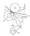
加熱定着装置から排紙ユニットへ至る記録材搬送路上には、加熱定着装置を通過する記録材の有無を検出する排紙センサユニットが設置されている。この排紙センサユニットは主に、排紙センサレバー29とフォトインタラプタ30により構成される。
On the recording material conveyance path from the heat fixing device to the paper discharge unit, a paper discharge sensor unit for detecting the presence or absence of the recording material passing through the heat fixing device is installed. The paper discharge sensor unit mainly includes a paper
図6、7は、この排紙センサユニットの概略構成を示す斜視図で、図7は、図6の反対方向からみた図である。排紙センサレバー29は、主としてポリアセタールなどの摺動性の高いプラスチック部材などでできており、先端の記録材通過部が定着ニップ部Nと排紙ローラニップ部を結ぶ線A(図4)を遮る位置に、ホームポジションとして設置される。排紙センサレバー29には、このレバー本体と直交する方向に突出する遮蔽部材29aが形成されており、Sを支点に一体的に回動するように構成されている。そして、記録材が通過する時には排紙センサレバー29が記録材搬送方向に倒れ(図3参照)、これに伴い遮蔽部材29aはフォトインタラプタ30の赤外線光を遮断する。記録材がない時には排紙センサレバー29はホームポジションに戻り、遮蔽部材29aはフォトインタラプタ30の赤外線光を遮断しない位置に来る(図1参照)。このように、排紙センサレバー29の動きによってフォトインタラプタ30の赤外線光のオン/オフを行い、記録材の有無を検出する。
6 and 7 are perspective views showing a schematic configuration of the paper discharge sensor unit, and FIG. 7 is a view seen from the opposite direction to FIG. The paper
さて、本実施形態における画像形成装置では、以下に説明するように、上記の如く設置された排紙センサユニットに、集熱板と温度検知センサにより構成される排紙温度検出ユニットが設けられる。 In the image forming apparatus according to the present embodiment, as will be described below, a paper discharge temperature detection unit including a heat collecting plate and a temperature detection sensor is provided in the paper discharge sensor unit installed as described above.
この排紙温度検出ユニットは、加熱定着装置から排出される画像定着後の記録材の非印字面の温度を検出するように構成される。記録材の非印字面側で温度検出することの利点として2点挙げられる。一つ目は、通常の片面印字印刷時にはトナーの定着されている面と逆の面で記録材が集熱板と接触することになるため、集熱板へのトナーの付着の影響を受けることが無い。つまり、集熱板に対してトナーが付着することで温度検知精度の低下を招くことが無い。二つ目としては、加熱ヒータ23から定着フィルム22を介して記録材の印字面側に主に熱エネルギーが付与されるので、非印字面で温度検知をすることにより、記録材印字面側から非印字面側への熱伝導による温度勾配の特性の違いを利用して記録材の特性を検知温度から予測することが可能となる。例えば、薄手の記録材の非印字面側の温度は、厚手の記録材の非印字面側の温度よりも高くなる。また、表面性が平滑な記録材の方が、表面性が粗い記録材より定着ニップ部で定着フィルム22との密着性が得られることから、熱エネルギーが伝わりやすくなり、その結果、非印字面側の温度が高くなる。
The paper discharge temperature detection unit is configured to detect the temperature of the non-printing surface of the recording material after image fixing discharged from the heat fixing device. There are two advantages of detecting the temperature on the non-printing surface side of the recording material. First, during normal single-sided printing, the recording material comes into contact with the heat collecting plate on the surface opposite to the surface on which the toner is fixed, so that it is affected by the adhesion of toner to the heat collecting plate. There is no. That is, the toner does not adhere to the heat collecting plate, and the temperature detection accuracy is not lowered. Secondly, since heat energy is mainly applied from the
図5は、排紙センサレバー29付近の詳細図である。排紙センサレバー29先端の記録材通過部には、熱容量の小さいアルミニウムやステンレスなどの厚み0.1mm程度の薄板でできた集熱板31がアウトサート成型などにより排紙センサレバー29と一体的に構成されており、バネなどの付勢手段により加熱定着装置から排出される記録材の非印字面側に接触する。
FIG. 5 is a detailed view of the vicinity of the paper
集熱板31は、定着ニップ部と排紙ローラニップ部を結ぶ線Aよりも上方に設置されている(図4参照)。定着ニップ部を通過した記録材の先端部は、まずは排紙センサレバー29のプラスチック部に接触する。さらに記録材が下流側に送られると排紙センサレバー29が回動し、集熱板31が記録材の非印字面側に接触する。このように、集熱板31の熱容量を小さくし、積極的に記録材と当接させることにより、集熱板31の温度を短時間で記録材の温度に応じて上昇させることが可能になる。ここで、集熱板31の熱容量を小さくするために、集熱板31は記録材搬送方向、および、記録材搬送方向と直交かつ記録材の幅と略平行方向の大きさを極力小さくすることが望ましい。
The
両面印字を行う場合は、2面目の通紙時に排紙センサレバー上の集熱板31は記録材の1面目の印字面と接触することになるため、集熱板表面へのトナーの付着が懸念される。この対策として、集熱板31の表面にPFA、PTFE等のフッ素樹脂コーティングや、UV塗装などの表面処理を、集熱板31の熱伝導に影響のない範囲で施してもよい。また、集熱板31の表面にPI(ポリイミド)などで被覆を施してもよい。
When performing double-sided printing, the
排紙センサレバー先端の集熱板31の裏面には、サーミスタなどの応答性の高い温度検知センサ(排紙温度センサ)32が接着等の方法で貼り付けられている。加熱定着装置から画像定着後の記録材Pが搬送されると、排紙センサレバー29が回動し、集熱板31が記録材Pの非印字面に接触し、記録材の熱を奪い、裏面に設置された排紙温度センサ32に熱を伝導して記録材の温度に依存した温度を検出する。このとき排紙温度センサ32は、排紙センサレバー29が回動した時、すなわち排紙センサレバー29が記録材有りを検知した時に記録材Pと集熱板31が接触する位置の真下に取り付けられており、集熱板内での温度勾配の影響を最小限にすることにより、記録材の温度に依存した検出温度の精度を高めている。また、記録材との摺動部に金属部材を使うことにより、摺動部の磨耗を防止し、排紙センサレバー29の耐久性を向上させることができる。
A highly sensitive temperature detection sensor (paper discharge temperature sensor) 32 such as a thermistor is attached to the back surface of the
このように、記録材の有無を検知する排紙センサレバー上に集熱板31とサーミスタなどの排紙温度センサ32を設けることにより、記録材の位置情報と温度情報を精度よく同期させることが可能になり、サーミスタから出力される温度情報が記録材のどの位置における情報かを精度よく検知することが可能になる。例えば、サーミスタの温度情報は記録材の先端部に比べ、後端部の方が上昇する傾向にあるので、記録材の位置情報と同期させることにより、より確実に記録材温度に依存した温度を検知することが可能になる。
In this way, by providing the
サーミスタは温度により抵抗値を変化させる素子であり、サーミスタチップの電極にデュメット線33を焼き付けた状態でガラスに封入されている。また排紙センサレバー29は、ステンレスなどの金属でできた2本の電極34がアウトサート成型などでプラスチック部と一体的に構成されている(図6、7参照)。前述のデュメット線33は、これら2本の電極に溶接される。さらに、これらの電極は制御回路14に接続されており、サーミスタで検出した温度情報を伝える。
The thermistor is an element that changes its resistance value according to temperature, and is enclosed in glass with a
電極34は、厚さ0.1mm程度の薄いステンレスなどの板金でできており、サーミスタの温度情報を制御回路14に伝える役割を果たすと同時に、排紙センサレバー29に回動力を付勢する機能をも併せ持っている。電極34の一方の端部は排紙センサレバー29のプラスチック部と一体的に構成され、サーミスタのデュメット線33と溶接されており、もう一方の端部は定着排紙ガイド28に固定された不図示の端子に接続されている。電極34は排紙センサレバー29が回動すると、排紙センサレバー29とともに動き、固定された端子接続部からねじられることにより、排紙センサレバー29をホームポジションに戻す方向に回動力を付勢する。また電極34は、排紙センサレバー29に適正な回動力を付勢し、かつ繰り返し応力を受けることによって電極自身が永久変形や破断などをおこさないよう、クランク形状にて構成される。
The
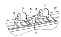
排紙センサレバー先端部について更に詳細に説明する。前述したように、排紙センサレバー先端部には熱容量の小さい材質でできた集熱板31が、熱伝導率の低いプラスチックの排紙センサレバー29と一体的に構成されている。ここで、集熱板31の裏面は排紙センサレバー部との接合部を除いて空洞35になっている。これにより、集熱部近傍の熱容量を小さくするとともに、集熱板31と排紙センサレバー29を断熱することにより、排紙温度センサ32に集まる熱を逃がさないようすることができ、排紙温度センサ32の応答性を高めることが可能になる。
The tip of the paper discharge sensor lever will be described in more detail. As described above, the
さらに、定着排紙ガイド28の排紙センサレバー近傍部について図8を用いて説明する。定着排紙ガイド28は、排紙センサレバー29が回動する位置に対して逃げ36を大きく取っており、記録材と排紙センサレバー29が接触する部分の近傍において記録材と定着排紙ガイド28の通紙面が接触しないように構成されている。これにより、集熱板近傍の熱を定着排紙ガイド28へと逃がさないようにして、記録材の温度に依存した検出温度の精度を高めている。また、排紙センサレバー29は排紙ローラ26と排紙コロ27のニップを軸方向(記録材の幅方向)に避けた位置に設置されており、記録材通過時には排紙ローラ26とオーバーラップするようになっており、排紙センサレバー29の付勢力によって記録材がたわむのを防いでいる。
Further, the vicinity of the paper discharge sensor lever of the fixing
以上の排紙センサレバー29に配置された排紙温度センサ32による検知温度は、前述したように定着ニップ部に搬送される記録材の種類によって影響を受けることが確認されており、この検知温度に応じて定着条件を自動的に変更することで、記録材の種類に依らずホットオフセット等の画像不良、記録材のカール等の記録材の変形を未然に防止し、安定した定着性能を得ることが可能となる。
As described above, it has been confirmed that the temperature detected by the paper
(排紙温度センサに基づく動作シーケンス)
以下では、各種の記録材上のトナー画像を加熱定着させた場合の本実施形態における排紙温度センサの検知温度推移および検知温度に基づく動作シーケンスについて、詳細に説明する。
(Operation sequence based on paper discharge temperature sensor)
Hereinafter, the detected temperature transition of the discharge temperature sensor and the operation sequence based on the detected temperature when the toner images on various recording materials are heated and fixed will be described in detail.
本実施形態における画像形成装置は例えば、プロセススピード320mm/secのレーザビームプリンタであり、1分間にLTRサイズの記録材が55枚プリントされる装置である。加熱定着装置の構成としては、厚み0.6mm、幅12mmのAlN基板上にAg/Pdペーストから形成される通電発熱体をスクリーン印刷してなる加熱用ヒータの摺動面に外径30mm、厚み40μmのSUS304のシームレス金属フィルムを基層として、その表層に厚み4μmのプライマ層、厚み10μmの抵抗調整されたフッ素樹脂層を順次被覆させて形成された定着フィルムを回転自在に配置してある加熱部材を使用した。また、加圧ローラとして、径22mmのアルミ芯金の外面に弾性層として厚み4mmの導電シリコンゴム、さらに表層にPFAチューブを被覆させたローラを使用した。上記定着部材と加圧ローラとの間に付与する加圧力は15kgfとした。また、上述のとおり定着ニップ部下流側に排紙センサレバー29を配置し、レバーの先端には厚み0.1mm、幅6mm、高さ8mmのSUS板を取り付け、その背面には、排紙温度センサ32として小型のサーミスタをエポキシ系接着剤にて感熱部を接着固定した。定着ニップ部中央からホームポジション時の排紙センサレバー29までの距離は定着ニップ部から排出された記録材の非印字面温度と排紙温度センサ32の相関が精度良く取れるよう記録材搬送方向で25mmの距離とした。
The image forming apparatus according to this embodiment is, for example, a laser beam printer with a process speed of 320 mm / sec, and is an apparatus that prints 55 LTR size recording materials per minute. As a configuration of the heat fixing device, an outer diameter of 30 mm and a thickness are formed on a sliding surface of a heating heater formed by screen-printing an electric heating element formed from an Ag / Pd paste on an AlN substrate having a thickness of 0.6 mm and a width of 12 mm. A heating member having a 40 μm SUS304 seamless metal film as a base layer, and a fixing film formed by sequentially coating a surface layer with a 4 μm thick primer layer and a 10 μm thick resistance-adjusted fluororesin layer. It was used. Further, as the pressure roller, a roller in which an outer surface of an aluminum cored bar having a diameter of 22 mm was coated with a conductive silicon rubber with a thickness of 4 mm as an elastic layer and a PFA tube on the surface layer was used. The pressure applied between the fixing member and the pressure roller was 15 kgf. Further, as described above, the paper
以上の構成で各種の記録材を連続プリントした際の排紙温度センサ32による検知温度推移を測定した。
The change in temperature detected by the paper
本明細書において「連続プリント」とは、先行する記録材が定着ニップ部を通過する時点で後続の記録材が画像形成部に供給され画像形成動作が既に開始されている状態が継続しており、先行する記録材の後端と後続の記録材の先端との距離(紙間)が略一定に維持されている状態をいう。本実施形態に即してより具体的に説明すると、加熱定着された記録材の後端が排紙センサレバー29を通り過ぎた時点で後続の記録材が既にレジストローラ6を過ぎてトナー画像の記録材上への転写が始められている状態が継続するプリント動作が、連続プリントとなる。
In this specification, “continuous printing” refers to the state in which the subsequent recording material is supplied to the image forming unit and the image forming operation has already started when the preceding recording material passes through the fixing nip portion. The state in which the distance between the trailing edge of the preceding recording material and the leading edge of the succeeding recording material is maintained substantially constant. More specifically, in accordance with the present embodiment, when the rear end of the heat-fixed recording material passes the paper
また実験では、条件を同一とするため、スタンバイ状態で加熱ヒータに通電されていない状態が長く継続され、加熱ヒータの温度が画像形成装置が設置された室温(機外温度)に最も近い状態(以後、朝一状態と記す)から各種の記録材の連続プリント動作を開始した。また、記録材は全てカット紙を使用した。 In the experiment, since the conditions are the same, the state in which the heater is not energized in the standby state continues for a long time, and the temperature of the heater is closest to the room temperature (outside temperature) where the image forming apparatus is installed ( Thereafter, the continuous printing operation of various recording materials was started from the morning. Further, cut paper was used for all recording materials.
使用した記録材は坪量64g/m2の表面性が平滑な薄紙A、坪量80g/m2で薄紙Aに比べ若干表面の粗さが粗い薄紙B、坪量が90g/ m2の表面性が非常に粗いラフ紙C、坪量が135g/ m2の表面性が平滑な厚紙Dであり、実験に用いた記録材のサイズは全てLTRサイズ(幅216mm、長さ279mm)とした。 The recording material used is thin paper A having a basis weight of 64 g / m 2 and a smooth surface, thin paper B having a basis weight of 80 g / m 2 and a slightly rougher surface than thin paper A, and a surface having a basis weight of 90 g / m 2 . A rough paper C having very rough properties, a thick paper D having a smooth surface property with a basis weight of 135 g / m 2 , and the recording materials used in the experiments were all LTR sizes (width 216 mm, length 279 mm).
実験の結果を図10に示す。図10において、横軸は連続プリント時の枚数、縦軸は排紙温度センサ32による検知温度を示す。図より明らかなように、表面が平滑な薄紙Aは最も検知温度が高く推移していることがわかる。また、薄紙Aより表面性が若干粗く、坪量が若干大きい薄紙Bは薄紙Aより検知温度が若干低く推移し、ラフ紙C、厚紙Dは薄紙AおよびBに比べて検知温度がかなり低く推移していることがわかる。これは、表面性が粗い記録材ほど、加熱部材の定着フィルムとの密着性が得られないことから定着フィルム表面から記録材への熱の伝導が悪く、また、表面性が平滑でも厚さの厚い記録材は熱容量が大きく、非印字面の温度は上昇しにくいことを示している。以上のことから、排紙温度センサ32の検知温度に基づいて、加熱定着された記録材の種類を判別できることが示される。
The result of the experiment is shown in FIG. In FIG. 10, the horizontal axis represents the number of sheets during continuous printing, and the vertical axis represents the temperature detected by the paper
次に、同様の連続プリント動作を薄紙Bおよびラフ紙Cを使用して、プリント開始時の排紙温度センサ32の検知温度(初期温度)が異なる場合について実験を行った。すなわち、(1)朝一状態からの連続プリント時の検知温度推移を測定した後、2分間ほどスタンバイ状態で画像形成装置を放置し、(2)加熱部材および加圧ローラがある程度温まった状態(以後、ホット状態と記す)からの連続プリント時の温度検知推移を測定した。
Next, the same continuous printing operation was performed using thin paper B and rough paper C, and an experiment was performed when the detected temperature (initial temperature) of the paper
測定結果を図11に示す。薄紙B−1およびラフ紙C−1は朝一状態からの連続プリント時、薄紙B−2およびラフ紙C−2はホット状態からの連続プリント時の検知温度推移を示す。図より、それぞれの記録材において、排紙温度センサ32の検知温度は朝一状態からの連続プリント時に比べホット状態からの連続プリント時の方が検知温度推移は高めとなり、またプリント動作開始からの検知温度の上昇は少ないことがわかる。これは、排紙センサレバー29が定着ニップ部に近い位置に配置されているために、プリント開始時の加熱部材および加圧ローラ付近の雰囲気温度を検知しているためである。
The measurement results are shown in FIG. The thin paper B-1 and the rough paper C-1 show the detected temperature transition during continuous printing from the morning state, and the thin paper B-2 and the rough paper C-2 show the detected temperature transition during continuous printing from the hot state. As shown in the figure, the detected temperature of the paper
また、さまざまな初期温度T0からの連続プリントを、薄紙B、ラフ紙Cおよび坪量105g/m2の表面性が平滑な厚紙Eについて繰り返し行い、各初期温度T0に対する連続プリント30枚目相当時の検知温度T3を測定したところ、図12に示すような結果となった。ここで初期温度T0とは、レーザビームプリンタがプリント信号を受信し、給紙駆動、各部の回転駆動等の画像形成動作を開始する直前の排紙温度センサ32による測定温度である。図より、初期温度T0によって各記録材の連続プリント30枚目での検知温度は変化しており、初期温度T0が高いほど連続プリント30枚目の検知温度は高くなることがわかる。また、薄紙Bと厚紙E、ならびに、厚紙Eとラフ紙Cとでは初期温度T0が同様の場合には、連続プリント30枚目時点での検知温度は異なり、その間に図示のような境界線を引く(制御式1および制御式2)ことで連続プリントされた記録材の種類を判別できることがわかる。
Also, continuous printing from various initial temperatures T0 is repeated for thin paper B, rough paper C, and thick paper E having a basis weight of 105 g / m 2 and having a smooth surface property, corresponding to the 30th continuous printing for each initial temperature T0. When the detected temperature T3 was measured, the results shown in FIG. 12 were obtained. Here, the initial temperature T0 is a temperature measured by the paper
そして、この判別結果に基づいて、加熱定着装置の温度制御、あるいは画像形成装置の記録材供給タイミング等にフィードバックすることによって記録材に与える熱量をコントロールすることが可能となる。 Based on the determination result, the amount of heat applied to the recording material can be controlled by feeding back to the temperature control of the heat fixing device or the recording material supply timing of the image forming apparatus.
本実施形態では、以上のような実験結果に基づいて排紙温度センサ32に基づく動作シーケンスを実行する。図9は、本実施形態に係る画像形成装置の連続プリント時における動作を示すフローチャートである。
In the present embodiment, an operation sequence based on the paper
画像形成装置がプリント信号を受信すると(ステップS101)、プリント動作を開始する前に排紙温度センサ32による初期温度T0を測定する(ステップS102)。
When the image forming apparatus receives the print signal (step S101), the initial temperature T0 is measured by the paper
次いで、初期温度T0に基づき図12に示したような実験結果に基づて定められた2つの制御式にそれぞれ初期温度T0を代入し、しきい値温度T1およびT2を決定する(ステップS103)。しきい値温度T1およびT2は、例えば次式で表される。 Next, the initial temperature T0 is assigned to two control equations determined based on the experimental results as shown in FIG. 12 based on the initial temperature T0, and threshold temperatures T1 and T2 are determined (step S103). . The threshold temperatures T1 and T2 are expressed by the following equations, for example.
T1=0.16・T0+62[℃]
T2=0.16・T0+70[℃]
T1 = 0.16 · T0 + 62 [° C]
T2 = 0.16 · T0 + 70 [° C.]
その後、給紙装置からの記録材の給紙動作、画像形成部における画像形成動作、加熱定着装置の加熱ヒータへの通電をそれぞれ開始し、排紙温度センサ32による温度モニターを継続する(ステップS104)。
Thereafter, the recording material feeding operation from the paper feeding device, the image forming operation in the image forming unit, and the energization to the heater of the heat fixing device are started, and the temperature monitoring by the paper
そして、例えば連続プリント時30枚目における排紙温度センサ32による検知温度T3を測定する(ステップS105)。ここでは連続プリント時30枚目における排紙温度センサ32による検知温度としたが、別の時点の検知温度を測定してもよい。
Then, for example, the temperature T3 detected by the paper
なお、ステップS103はステップS104またはステップS105の後に実行しても構わない。 Note that step S103 may be executed after step S104 or step S105.
次に、排紙温度T3がT2以上あるかどうかを判断する(ステップS106)。ここで排紙温度T3がT2以上ある場合には、排紙温度センサ32による検知温度が十分に高く、記録材として表面が平滑な薄紙が加熱定着されていると判断される。この結果、スループット(所定時間内に搬送される記録材の枚数)を維持しつつ、加熱定着装置の加熱ヒータの温度を所定温度(例えば5℃)ダウンさせることにより、記録材に余分な加熱をしてしまうことを防止する(ステップS107)。
Next, it is determined whether or not the paper discharge temperature T3 is equal to or higher than T2 (step S106). Here, when the paper discharge temperature T3 is equal to or higher than T2, it is determined that the temperature detected by the paper
一方、ステップS106において、排紙温度T3がT2未満である場合は、T3がT1以上であるかどうかを判断する(ステップS108)。ここでT3がT1以上ある場合(すなわち、T1≦T3<T2の場合)には、最適な加熱定着が実施されていると判断し、現行のスループットおよび温度制御を維持し、プリント動作を継続する(ステップS109)。 On the other hand, if the paper discharge temperature T3 is lower than T2 in step S106, it is determined whether T3 is equal to or higher than T1 (step S108). Here, when T3 is equal to or greater than T1 (that is, when T1 ≦ T3 <T2), it is determined that optimum heat-fixing is performed, and the current throughput and temperature control are maintained, and the printing operation is continued. (Step S109).
また、ステップS108において、排紙温度T3がT1未満である場合は、記録材への加熱が不十分であり、定着性能を損なう可能性があるため、紙間を広げてスループットを下げる(ステップS110)。例えば、図13に示すようなプリント枚数とスループットとの関係を記述したテーブルに従いスループットを下げる。同図において、「ppm」とは、1分間当たりのプリント枚数を示すスループットの単位である。なお、ここではスループットを下げることで定着性能を満足させる方法を提示したが、これは、紙間を広げ、その間に加圧ローラを十分に加熱させることで、記録材に与えられる熱量を加圧ローラ側からも補充することにより増加させる方法を示したものであり、加熱ヒータ制御温度を高くする等、記録材に与えられる熱量を増す別の方法を採用してもよい。 In step S108, if the paper discharge temperature T3 is lower than T1, the recording material is not sufficiently heated and the fixing performance may be impaired. Therefore, the gap between the sheets is widened to reduce the throughput (step S110). ). For example, the throughput is lowered according to a table describing the relationship between the number of prints and the throughput as shown in FIG. In the figure, “ppm” is a unit of throughput indicating the number of prints per minute. Here, a method of satisfying the fixing performance by lowering the throughput was presented, but this is to pressurize the amount of heat given to the recording material by widening the space between the sheets and heating the pressure roller sufficiently during that time. This is a method of increasing the amount by replenishing from the roller side, and another method of increasing the amount of heat given to the recording material, such as increasing the heater control temperature, may be adopted.
以上により排紙温度センサ32による検知温度に基づいて、搬送される記録材の種類に応じて自動的に記録材へ与えられる熱量をコントロールして、最終ページまでプリント動作を継続し(ステップS111、S112)、最終ページを加熱定着後にプリント動作を終了し、設定した閾値T1およびT2をクリアする(ステップS113)。
As described above, based on the temperature detected by the paper
以上説明した本実施形態の効果を確認するため、加熱条件をまったく変更しなかったとき(比較例1)、および初期温度T0に関係なくしきい値温度T1およびT2をそれぞれ70℃および77℃と一定温度に設定したとき(比較例2)との比較実験を行った。本実施形態、比較例1、比較例2のそれぞれで連続プリント動作を行い、排紙トレイ上の積載性能(仕様上250枚積載)、定着性能を比較した。なお、排紙トレイ上の積載性能は記録材がトレイ上から落ちるまでに何枚積載できたかをテストした。定着性能はプリント後の記録材の印字面にテープを貼り、そのテープを剥がしたときにどの程度テープにより画像が剥ぎ取られたかを判断した。 In order to confirm the effect of this embodiment described above, when the heating conditions were not changed at all (Comparative Example 1), the threshold temperatures T1 and T2 were kept constant at 70 ° C. and 77 ° C., respectively, regardless of the initial temperature T0. A comparative experiment was performed with respect to when the temperature was set (Comparative Example 2). A continuous printing operation was performed in each of the present embodiment, Comparative Example 1, and Comparative Example 2, and the stacking performance on the paper discharge tray (250 stacking on the specification) and the fixing performance were compared. The stacking performance on the paper discharge tray was tested to see how many sheets of recording material could be stacked before dropping from the tray. The fixing performance was determined by how much the image was peeled off by the tape when the tape was attached to the printing surface of the recording material after printing and the tape was peeled off.
プリントした記録材は前述した薄紙Bおよびラフ紙C、厚紙Eであり、排紙温度センサ32によるプリント動作前の初期温度がそれぞれ23℃、50℃、70℃の各条件でそれぞれ5回実施し、積載枚数はその平均値、定着性能は5回全ての実験において全く問題なかった場合を○、画像欠損が2回以内を△、画像欠損が3回以上の場合を×として判断した。比較結果を図14に示す。
The printed recording materials are the thin paper B, the rough paper C, and the thick paper E described above, and each of the initial temperatures before the printing operation by the paper
同図(a)によれば、薄紙Bでは、適正に判断された記録材への熱量を絞った本実施形態では、定着性能を損なわずに積載性も十分となっているのに対し、排紙温度センサ32による加熱ヒータの温度制御を実施しなかった比較例1では積載性が劣っている。これは、排紙トレイ上にカールが大きい記録材が溜まり、後続の記録材が既に積載した記録材を排紙トレイ上から押すことで排紙トレイ上から落下させてしまったことによる。また、初期温度T0に依らずしきい値温度を一定にした比較例2では、初期温度50℃および70℃では、薄紙を正しく識別できたが、初期温度23℃の場合には薄紙を識別できない場合があり、結果として、加熱ヒータへの温度制御フィードバックを行わない場合が5回のテスト中3回あったため、比較例1と同様に積載性が悪化した場合があった。
According to FIG. 9A, the thin paper B has sufficient stackability without deteriorating the fixing performance in the present embodiment in which the heat amount to the recording material determined appropriately is reduced. In Comparative Example 1 in which the temperature control of the heater by the
次に、同図(b)はラフ紙Cを連続プリントした場合の結果を示している。本実施形態では、図13のようなテーブルに従い、枚数に応じてスループットを落とすことにより定着不良を回避できたが、比較例1では、定着不良が40枚目以降に発生してしまった。また、比較例2においても、5回のテスト中2回はラフ紙と識別できず、定着不良が発生してしまった。 Next, FIG. 4B shows the result when the rough paper C is continuously printed. In this embodiment, the fixing failure can be avoided by reducing the throughput according to the number of sheets according to the table as shown in FIG. 13, but in Comparative Example 1, the fixing failure occurs after the 40th sheet. Also, in Comparative Example 2, it was not possible to distinguish from rough paper twice out of five tests, and fixing failure occurred.
また、同図(c)は厚紙Eを連続プリントした場合の結果を示している。本実施形態および比較例1では、加熱ヒータの温度制御、スループットに変更を加えないため、良好な積載性、定着性が得られたのに対して、比較例2では初期温度23℃では定着性を上げるためにスループットダウンの動作が、初期温度70℃では加熱ヒータの温度を5℃下げてしまう制御が入ったため、それぞれの場合で積載性、定着性能を悪化させてしまうことがあった。 FIG. 2C shows the result when the thick paper E is continuously printed. In this embodiment and Comparative Example 1, since the temperature control and the throughput of the heater are not changed, good stackability and fixability are obtained, whereas in Comparative Example 2, the fixability is obtained at an initial temperature of 23 ° C. In order to increase the throughput, since the operation of reducing the throughput has been controlled to lower the temperature of the heater by 5 ° C. at the initial temperature of 70 ° C., the loadability and the fixing performance may be deteriorated in each case.
以上、本実施形態によれば、低熱容量の排紙温度センサ32を定着ニップ直後の非印字面側に配置し、プリント開始時の初期温度T0に応じたしきい値T1、T2を設定し、連続プリント時の所定時点で排紙温度T3を測定し、そのT3のT1,T2との比較結果に応じて定着制御をを行うことにより、ホットオフセット、カール/積載不良、定着不良等の不具合を防止することが可能となる。
As described above, according to the present embodiment, the
なお、上述の本実施形態によれば、プリント開始時における初期温度T0に応じて設定されるしきい値T1,T2と、連続プリント時の所定時点で排紙温度T3との比較結果に基づいて、実質的に記録材の種類を判別することができる。しかし、本発明の目的は必ずしも記録材の種類を判別することではなく、プリント開始時の排紙温度センサ32によって検出される初期温度およびその後の検出温度の推移に応じて記録材へ与える熱量を変更し、最適な加熱定着を実施することにある。よって、排紙温度センサ32による初期検知温度T0とその後の排紙温度センサ32による検知温度の温度変化の度合い(検知温度の傾き)、連続プリント時の所定時点における検知温度等の検知温度変化の推移によって記録材へ与える熱量をコントロールする方法が実現される限り、本発明はその検知タイミング、熱量コントロール方法等に関して限定されるものではない。
According to the above-described embodiment, the thresholds T1 and T2 set according to the initial temperature T0 at the start of printing and the comparison result between the discharge temperature T3 at a predetermined time point during continuous printing. The type of recording material can be substantially discriminated. However, the object of the present invention is not necessarily to determine the type of the recording material, but the amount of heat applied to the recording material according to the transition of the initial temperature detected by the paper
また、本実施形態では、プリント開始時の初期温度T0を排紙温度センサ32により測定する方法を示した。排紙温度センサ32により測定される初期温度T0は定着装置近傍の雰囲気温度に相当するのだが、この代わりに、加熱定着装置の近傍に設けられる別の温度検知素子により、その雰囲気温度に相当する初期温度T0を測定することにしてもよい。あるいは、ヒータ温度検知素子であるサーミスタ23aにより初期温度T0を測定してもよいであろう。サーミスタ23aの測定対象は加熱ヒータ23の温度であるが、上記雰囲気温度に大きく関わるので、これでも当然のことながら本発明の目的を達成することができる。
In the present embodiment, the method of measuring the initial temperature T0 at the start of printing by the paper
■ 第2の実施形態 ■
第2の実施形態の画像形成装置の構成を図15に示す。図15において、第1の実施形態として示した図1と同一の構成要素には同一の参照番号を付し、説明を省略する。また、本実施形態における加熱定着装置の構成も第1の実施形態と同様であるので、図2〜8を援用することにする。
■ Second Embodiment ■
The configuration of the image forming apparatus of the second embodiment is shown in FIG. In FIG. 15, the same components as those in FIG. 1 shown as the first embodiment are denoted by the same reference numerals, and the description thereof is omitted. In addition, since the configuration of the heat fixing apparatus in the present embodiment is the same as that in the first embodiment, FIGS.
本実施形態では、画像形成装置の設置されている環境(室温)を検知するためのサーミスタ等の外気温センサ19が、例えば本体側面に配置されており、外気温センサ19は機外の温度を正確に検知するように、外気を機内に取り込んで機内の昇温を防止する冷却ファン18の近傍に配置されている。これにより外気温センサ19は画像形成装置が設置されている室温を正確に検知することが可能となる。
In the present embodiment, an outside
本実施形態では、画像形成装置の使用される環境に応じて、第1の実施形態で示した排紙温度センサ32による記録材の判別をより正確に実施する方法を提案する。
The present embodiment proposes a method for more accurately performing recording material discrimination by the paper
以下、本実施形態による排紙温度センサを用いた制御方法について説明する。通常、画像形成措置が配置された環境によって給紙トレイ内に積まれた記録材の温度はその環境の温度に近い温度に保たれる。また、画像形成装置が設置された環境によって、加熱定着装置の加熱具合が同様であっても加熱定着装置周辺の温度は対流等の影響を受けて異なってくる。よって、画像形成装置が設置された環境の温度が低い場合と高い場合とでは、最適な加熱定着を実施した場合であっても、排紙温度センサによる検知温度は異なってくる。また、特にフィルム加熱方式の加熱定着装置では、低熱容量のフィルムを使用しているため、画像形成装置が設置されている環境に応じて連続プリントの枚数に応じて加熱ヒータの温調温度を細かに制御する方法がとられており、その具体的温調制御の一例を挙げると図17のようになる。同図において、横軸は朝一状態からの連続プリント枚数、縦軸は加熱ヒータ制御温度を示す。 Hereinafter, a control method using the paper discharge temperature sensor according to the present embodiment will be described. Normally, the temperature of the recording material stacked in the paper feed tray is maintained at a temperature close to the temperature of the environment due to the environment in which the image forming unit is arranged. In addition, depending on the environment in which the image forming apparatus is installed, the temperature around the heat fixing device varies depending on the influence of convection and the like even if the heating condition of the heat fixing device is the same. Therefore, the temperature detected by the paper discharge temperature sensor differs between the case where the temperature of the environment where the image forming apparatus is installed is low and the case where the temperature is high even when the optimum heat fixing is performed. In particular, the film heating type heat fixing device uses a low heat capacity film, so the temperature of the heater is finely adjusted according to the number of continuous prints according to the environment where the image forming apparatus is installed. FIG. 17 shows an example of specific temperature control. In the figure, the horizontal axis indicates the number of continuous prints from the morning state, and the vertical axis indicates the heater control temperature.
同図に示すように、例えば高温環境(例えば、室温30℃以上)に画像形成装置が設置されている場合には、給紙トレイ内の記録材の温度も環境温度に近くなっており、加熱定着装置において記録材に与える熱量を低く抑えても十分な定着性能が得られることから、加熱ヒータの制御温度を低めに設定してある。一方で常温環境(例えば、室温20℃〜30℃)、低温環境(例えば、室温20℃以下)ではそれぞれ給紙トレイ内の記録材の温度を考慮して加熱ヒータの制御温度が決められており、低温環境になるほど、加熱ヒータの制御温度を高く設定することで環境に依らず同等の定着性能が得られるようにしている。
As shown in the figure, for example, when the image forming apparatus is installed in a high temperature environment (for example, a room temperature of 30 ° C. or higher), the temperature of the recording material in the paper feed tray is also close to the environmental temperature, and heating is performed. Since sufficient fixing performance can be obtained even if the amount of heat applied to the recording material in the fixing device is kept low, the control temperature of the heater is set low. On the other hand, in a normal temperature environment (for example,
同図において、プリント枚数に応じて加熱ヒータの制御温度を徐々に下げているのは、記録材へ与える熱量を一定に保つためである。すなわち、連続プリントによって紙間等で加熱ヒータの周りに配置した各種加熱部材や加圧ローラが徐々に昇温することから、例えば、加圧ローラが十分に加熱された状態の場合には、非印字面側からも記録材へ熱量が与えられ、この熱量が記録材上のトナー像の加熱にも寄与するため、加熱ヒータの制御温度を徐々に下げても十分な定着性能が得られることによる。 In the figure, the reason why the control temperature of the heater is gradually lowered according to the number of prints is to keep the amount of heat applied to the recording material constant. That is, since various heating members and pressure rollers arranged around the heater are gradually heated between paper sheets by continuous printing, for example, when the pressure roller is sufficiently heated, Because the amount of heat is also given to the recording material from the printing surface side and this amount of heat also contributes to the heating of the toner image on the recording material, sufficient fixing performance can be obtained even if the control temperature of the heater is gradually lowered. .
このように、特にフィルム加熱方式では、画像形成装置が設置されている環境に応じて加熱ヒータの制御温度を最適化する等の方法がとられており、第1の実施形態で示した排紙温度センサによる記録材の識別および識別結果に応じた記録材へ与えられる熱量コントロールへのフィードバックの最適値が画像形成装置の設置されている環境に応じて異なってくる。 As described above, particularly in the film heating method, a method such as optimizing the control temperature of the heater according to the environment in which the image forming apparatus is installed is adopted. The paper discharge shown in the first embodiment The optimum value of the feedback to the heat quantity control given to the recording material according to the identification of the recording material by the temperature sensor and the identification result varies depending on the environment where the image forming apparatus is installed.
そこで、プリント開始時の排紙検知センサによる初期温度T0に応じて各記録材の連続プリント30枚目時点での検知温度がどのように変化するかを各環境で確認した。画像形成装置が設置された環境温度としては、室温15℃、25℃、35℃の各環境とした。使用した記録材は第1の実施形態と同様の薄紙B、ラフ紙C、厚紙Eである。排紙温度センサ32による検知温度の結果を図18A〜18Cに示す。これらの結果より、画像形成装置が設置されている環境により初期温度T0が同等であっても、連続プリント30枚目の排紙温度センサ32による検知温度は若干異なってくることがわかる。
Therefore, it was confirmed in each environment how the detected temperature at the time of the 30th continuous printing of each recording material changes according to the initial temperature T0 by the paper discharge detection sensor at the start of printing. The environmental temperature at which the image forming apparatus was installed was a room temperature of 15 ° C., 25 ° C., and 35 ° C. The recording materials used are thin paper B, rough paper C, and thick paper E as in the first embodiment. The results of the temperature detected by the paper
以上のことから、記録材の種類を判別する制御式1および2を各環境温度によって変更することで、識別精度を高めることができるといえる。
From the above, it can be said that the identification accuracy can be improved by changing the
そこで、以下では、排紙温度センサによる記録材識別および記録材へ与える熱量をコントロールするための制御シーケンスを、画像形成装置が設置されている環境温度に応じて変更する方法を説明する。 Therefore, hereinafter, a method for changing the control sequence for controlling the recording material identification by the paper discharge temperature sensor and the heat amount applied to the recording material according to the environmental temperature in which the image forming apparatus is installed will be described.
図16は、本実施形態に係る画像形成装置の連続プリント時における動作を示すフローチャートである。 FIG. 16 is a flowchart showing an operation during continuous printing of the image forming apparatus according to the present embodiment.
画像形成装置がプリント信号を受信すると(ステップS201)、外気温センサ19により画像形成装置が設置されている環境の温度Teを測定するとともに、この測定結果に基づき加熱ヒータの制御温度プロファイルを決定し(ステップS202)、ヒータへの通電、画像形成動作の開始、記録材上の未定着画像の加熱定着を順次実施する(ステップS203)。
When the image forming apparatus receives the print signal (step S201), the
その後、ヒータへの通電が開始されてから所定時間後の排紙温度センサ32による初期温度T0を測定する(ステップS204)。第1の実施形態では、ヒータへの通電前に、排紙温度センサ32による初期温度T0の測定を行ったが、本実施形態のように、ヒータへの通電を開始してから所定時間後の排紙温度センサ32による検知温度を初期温度T0としてもよい。この場合、加熱定着装置が回転駆動することで、若干排紙温度センサ32の検知温度が高くなるが、加熱定着装置の加熱具合によってこの検知温度が影響を受けるため、定着ニップ直後の雰囲気温度および加熱定着装置の加熱状態の双方に影響を受けた温度を検知することになる。また、初期温度T0の測定方法は以上の方法に限らず、加熱定着装置の加熱具合がわかる方法であれば、その検知タイミングは問わない。
Thereafter, the initial temperature T0 is measured by the paper
次に、初期温度T0と環境検知温度Teの双方に基づいてしきい値温度T1およびT2を決定する(ステップS205)。しきい値温度T1およびT2は、例えば次式で表される。 Next, threshold temperatures T1 and T2 are determined based on both the initial temperature T0 and the environment detection temperature Te (step S205). The threshold temperatures T1 and T2 are expressed by the following equations, for example.
T1=0.25・Te+0.16・T0+57.75[℃]
T2=0.25・Te+0.16・T0+65.75[℃]
T1 = 0.25 · Te + 0.16 · T0 + 57.75 [° C.]
T2 = 0.25 · Te + 0.16 · T0 + 65.75 [° C.]
その後、連続プリントを継続し、例えば30枚目における排紙温度センサ32による検知温度T3を測定する(ステップS206)。なお、ステップS105はステップS206の後に実行しても構わない。以降の処理は第1の実施形態におけるステップS106以降と同様であるが、説明すると次のようになる。
Thereafter, continuous printing is continued, and for example, the temperature T3 detected by the paper
排紙温度T3がT2以上あるかどうかを判断する(ステップS207)。ここで排紙温度T3がT2以上ある場合には、排紙温度センサ32による検知温度が十分に高く、記録材として表面が平滑な薄紙が加熱定着されていると判断される。この結果、スループット(所定時間内に搬送される記録材の枚数)を維持しつつ、加熱定着装置の加熱ヒータの温度を所定温度(例えば5℃)ダウンさせることにより、記録材に余分な加熱をしてしまうことを防止する(ステップS208)。
It is determined whether or not the paper discharge temperature T3 is equal to or higher than T2 (step S207). Here, when the paper discharge temperature T3 is equal to or higher than T2, it is determined that the temperature detected by the paper
一方、ステップS207において、排紙温度T3がT2未満である場合は、T3がT1以上であるかどうかを判断する(ステップS209)。ここでT3がT1以上ある場合(すなわち、T1≦T3<T2の場合)には、最適な加熱定着が実施されていると判断し、現行のスループットおよび温度制御を維持し、プリント動作を継続する(ステップS210)。 On the other hand, if the paper discharge temperature T3 is lower than T2 in step S207, it is determined whether T3 is equal to or higher than T1 (step S209). Here, when T3 is equal to or greater than T1 (that is, when T1 ≦ T3 <T2), it is determined that optimum heat-fixing is performed, and the current throughput and temperature control are maintained, and the printing operation is continued. (Step S210).
また、ステップS209において、排紙温度T3がT1未満である場合は、記録材への加熱が不十分であり、定着性能を損なう可能性があるため、紙間を広げてスループットを下げる(ステップS211)。 In step S209, if the paper discharge temperature T3 is lower than T1, the recording material is not sufficiently heated, and the fixing performance may be impaired. ).
以上により排紙温度センサ32による検知温度に基づいて、搬送される記録材の種類に応じて自動的に記録材へ与えられる熱量をコントロールして、最終ページまでプリント動作を継続し(ステップS212、S213)、最終ページを加熱定着後にプリント動作を終了し、設定した閾値T1およびT2をクリアする(ステップS214)。
As described above, based on the temperature detected by the paper
なお、本実施形態および第1の実施形態においては、連続プリント30枚目の時点における排紙温度センサ32による検知温度T3をしきい値温度T1およびT2と比較してその後の記録材へ与える熱量を変更しているが、連続プリント中のどのタイミングでT3を検知してフィードバックしても良い。例えば、連続プリント20枚目〜35枚目の間にそれぞれの枚数に応じたしきい値温度T1およびT2を初期温度T0および環境温度Teから決定し、順次判断を行う方法でも良いし、20枚目〜35枚目の最大温度もしくは平均温度をT3として判断する方法であっても良い。
In this embodiment and the first embodiment, the amount of heat given to the subsequent recording material by comparing the detected temperature T3 by the paper
また、本実施形態では、画像形成装置の設置されている環境温度Teを検知してその情報をもとにしきい値温度T1およびT2を決定する方法を示したが、記録材に含まれる水分もカールや定着性能に影響を与えることがわかっており、環境湿度を検知する素子を画像形成装置に設け、更にその情報をもとにしきい値温度T1およびT2を決定する方法を導入すればさらに記録材の種類を識別する精度が高くなることも考えられる。 In the present embodiment, the method of detecting the environmental temperature Te in which the image forming apparatus is installed and determining the threshold temperatures T1 and T2 based on the information is shown. However, moisture contained in the recording material is also included. It has been found that it will affect the curling and fixing performance. If an element for detecting the environmental humidity is provided in the image forming apparatus and a method for determining the threshold temperatures T1 and T2 based on the information is introduced, further recording is performed. It is conceivable that the accuracy of identifying the type of material is increased.
本実施形態の効果を確認するため、第1の実施形態で示した画像形成装置、加熱定着装置において25℃環境での制御シーケンスのみを使用して各環境(15℃、25℃、35℃環境)で様々な記録材を加熱定着した場合(比較例)とで、ホットオフセットの発生頻度、排紙トレイ上への積載枚数、定着性能を比較した。その結果、本実施形態で示した環境温度によりしきい値温度を決定する方が記録材識別精度が高く、不具合の発生がさらに減少した。 In order to confirm the effect of this embodiment, the image forming apparatus and heat fixing apparatus shown in the first embodiment use only the control sequence in the 25 ° C. environment (15 ° C., 25 ° C., 35 ° C. environment). ) And the case where various recording materials were heated and fixed (comparative example), the frequency of occurrence of hot offset, the number of sheets loaded on the paper discharge tray, and the fixing performance were compared. As a result, the recording material identification accuracy is higher when the threshold temperature is determined based on the environmental temperature shown in the present embodiment, and the occurrence of defects is further reduced.
以上、本実施形態では、第1の実施形態の構成に、設置環境の温度および/または湿度を検知する手段を更に備え、この検知結果および排紙温度センサによる初期温度の検知結果に基づいて記録材を判別するしきい値を決定するようにしたので、画像形成装置が使用される環境や加熱定着装置の加熱状態に依らず、正確な記録材の識別および、記録材へ与える熱量のコントロールを行うことが可能になる。これにより、カール/積載性悪化やホットオフセット、定着不良という課題を記録材の種類に依らず未然に防ぎ、良好な品質で記録材上の未定着画像を加熱定着することができる。 As described above, in the present embodiment, the configuration of the first embodiment further includes means for detecting the temperature and / or humidity of the installation environment, and recording is performed based on the detection result and the detection result of the initial temperature by the paper discharge temperature sensor. Since the threshold for discriminating the material is determined, it is possible to accurately identify the recording material and control the amount of heat applied to the recording material regardless of the environment in which the image forming apparatus is used and the heating state of the heat fixing device. It becomes possible to do. As a result, problems such as curling / stacking deterioration, hot offset, and fixing failure can be prevented regardless of the type of recording material, and an unfixed image on the recording material can be heat-fixed with good quality.
Claims (5)
発熱体を内包した回転体と、この回転体に圧接する加圧部材とを有し、前記回転体と前記加圧部材との圧接ニップ部に、トナー画像が形成された記録材を搬送し前記発熱体の熱を加えつつ通過させることで前記トナー画像を記録材上に定着させる加熱定着部と、
を備える画像形成装置であって、
前記圧接ニップ部よりも記録材移動方向下流側で記録材の温度を検知するための温度センサと、
先行する記録材が前記圧接ニップ部を通過する時点で後続の記録材が前記画像形成部に供給されて画像形成動作が開始されている状態を継続させる連続プリント動作を行う場合において、その連続プリント動作の初期時点で前記温度センサにより検知された第1の温度と、当該連続プリント動作途中における所定の時点で前記温度センサにより検知された第2の温度とに基づいて、後続の記録材に与える熱量を制御する制御手段と、
を有することを特徴とする画像形成装置。 An image forming unit for forming a toner image on a recording material;
A rotating body including a heating element, and a pressure member pressed against the rotating body, and a recording material on which a toner image is formed is conveyed to a pressure nip portion between the rotating body and the pressure member. A heating and fixing unit for fixing the toner image on the recording material by passing the heating element while applying heat;
An image forming apparatus comprising:
A temperature sensor for detecting the temperature of the recording material on the downstream side in the recording material moving direction from the pressure nip,
In a case where a continuous printing operation is performed in which the state in which the subsequent recording material is supplied to the image forming unit and the image forming operation is started when the preceding recording material passes through the press-contact nip portion, the continuous printing is performed. Based on the first temperature detected by the temperature sensor at the initial time of the operation and the second temperature detected by the temperature sensor at a predetermined time during the continuous printing operation, it is given to the subsequent recording material. Control means for controlling the amount of heat;
An image forming apparatus comprising:
前記第1の温度に基づいて前記第2の温度に対するしきい値を設定する手段と、
設定された前記しきい値と前記第2の温度との比較を行い、その比較結果に応じて、前記後続の記録材に与える熱量の制御量を決定する手段と、
を含むことを特徴とする請求項1に記載の画像形成装置。 The control means includes
Means for setting a threshold for the second temperature based on the first temperature;
Means for comparing the set threshold value with the second temperature, and determining a control amount of the amount of heat given to the subsequent recording material according to the comparison result;
The image forming apparatus according to claim 1, further comprising:
前記制御手段は、更に前記連続プリント動作前における前記検出手段による検出結果に基づいて、前記後続の記録材に与える熱量を制御することを特徴とする請求項1に記載の画像形成装置。 It further has a detecting means for detecting the temperature or humidity of the outside air,
The image forming apparatus according to claim 1, wherein the control unit further controls a heat amount applied to the subsequent recording material based on a detection result by the detection unit before the continuous printing operation.
前記検出手段による検出結果および前記第1の温度に基づいて前記第2の温度に対するしきい値を設定する手段と、
設定された前記しきい値と前記第2の温度との比較を行い、その比較結果に応じて、前記後続の記録材に与える熱量の制御量を決定する手段と、
を含むことを特徴とする請求項4に記載の画像形成装置。 The control means includes
Means for setting a threshold value for the second temperature based on a detection result by the detection means and the first temperature;
Means for comparing the set threshold value with the second temperature, and determining a control amount of the amount of heat given to the subsequent recording material according to the comparison result;
The image forming apparatus according to claim 4, further comprising:
Priority Applications (9)
| Application Number | Priority Date | Filing Date | Title |
|---|---|---|---|
| JP2004054638A JP4262119B2 (en) | 2004-02-27 | 2004-02-27 | Image forming apparatus |
| EP05002513A EP1569046A1 (en) | 2004-02-27 | 2005-02-07 | Image-forming apparatus with a detector unit for detecting the temperature of a recording medium |
| US11/055,786 US7280775B2 (en) | 2004-02-27 | 2005-02-11 | Image-forming apparatus and recording-medium-temperature detector unit used in the same |
| US11/060,678 US7187878B2 (en) | 2004-02-27 | 2005-02-18 | Image forming apparatus and its control method |
| US11/062,634 US7215899B2 (en) | 2004-02-27 | 2005-02-23 | Image forming apparatus having temperature sensing element for sensing temperature of recording material |
| EP05004086.4A EP1569048B1 (en) | 2004-02-27 | 2005-02-24 | Image forming appartus having temperature sensing element for sensing temperature of recording material |
| CNB2005100087383A CN100435042C (en) | 2004-02-27 | 2005-02-25 | Image-forming apparatus with a detector unit for detecting the temperature of a recording medium |
| CNB2005100087379A CN100409119C (en) | 2004-02-27 | 2005-02-25 | Image forming apparatus and its control method |
| CNB2005100529232A CN100440069C (en) | 2004-02-27 | 2005-02-28 | Image-forming apparatus with a detector unit for detecting the temperature of a recording medium |
Applications Claiming Priority (1)
| Application Number | Priority Date | Filing Date | Title |
|---|---|---|---|
| JP2004054638A JP4262119B2 (en) | 2004-02-27 | 2004-02-27 | Image forming apparatus |
Publications (3)
| Publication Number | Publication Date |
|---|---|
| JP2005242189A JP2005242189A (en) | 2005-09-08 |
| JP2005242189A5 JP2005242189A5 (en) | 2007-05-10 |
| JP4262119B2 true JP4262119B2 (en) | 2009-05-13 |
Family
ID=34879758
Family Applications (1)
| Application Number | Title | Priority Date | Filing Date |
|---|---|---|---|
| JP2004054638A Expired - Fee Related JP4262119B2 (en) | 2004-02-27 | 2004-02-27 | Image forming apparatus |
Country Status (3)
| Country | Link |
|---|---|
| US (1) | US7187878B2 (en) |
| JP (1) | JP4262119B2 (en) |
| CN (1) | CN100409119C (en) |
Cited By (1)
| Publication number | Priority date | Publication date | Assignee | Title |
|---|---|---|---|---|
| US8725019B2 (en) | 2010-10-08 | 2014-05-13 | Ricoh Company, Ltd. | Fixing device, fixing device control method, and image forming apparatus |
Families Citing this family (14)
| Publication number | Priority date | Publication date | Assignee | Title |
|---|---|---|---|---|
| JP4630673B2 (en) * | 2004-02-03 | 2011-02-09 | キヤノン株式会社 | Fixing device |
| US7215899B2 (en) * | 2004-02-27 | 2007-05-08 | Canon Kabushiki Kaisha | Image forming apparatus having temperature sensing element for sensing temperature of recording material |
| JP2006023377A (en) * | 2004-07-06 | 2006-01-26 | Canon Inc | Image forming apparatus |
| JP2006084821A (en) * | 2004-09-16 | 2006-03-30 | Canon Inc | Heat fixing apparatus |
| JP2007078875A (en) * | 2005-09-12 | 2007-03-29 | Canon Inc | Image forming apparatus and recording material conveyance method |
| JP5267187B2 (en) * | 2009-02-13 | 2013-08-21 | セイコーエプソン株式会社 | Cylindrical shaft, transport roller, transport unit, and printing apparatus |
| JP5453831B2 (en) * | 2009-02-13 | 2014-03-26 | セイコーエプソン株式会社 | Printing device |
| JP2011008171A (en) * | 2009-06-29 | 2011-01-13 | Konica Minolta Business Technologies Inc | Image forming apparatus |
| CN102023541A (en) * | 2009-09-15 | 2011-04-20 | 株式会社东芝 | Photographic fixing device, imaging device and imaging method |
| JP5640404B2 (en) * | 2010-03-10 | 2014-12-17 | 株式会社リコー | Fixing apparatus, image forming apparatus, and fixing condition control method |
| JP5671848B2 (en) * | 2010-06-23 | 2015-02-18 | 富士ゼロックス株式会社 | Image forming apparatus |
| JP6942947B2 (en) * | 2016-09-21 | 2021-09-29 | 富士フイルムビジネスイノベーション株式会社 | Fixing device and image forming device |
| JP6410785B2 (en) * | 2016-12-09 | 2018-10-24 | キヤノン株式会社 | Fixing device |
| JP2019105699A (en) * | 2017-12-11 | 2019-06-27 | 京セラドキュメントソリューションズ株式会社 | Fixing device and image forming apparatus |
Family Cites Families (44)
| Publication number | Priority date | Publication date | Assignee | Title |
|---|---|---|---|---|
| JP2516886B2 (en) | 1987-06-16 | 1996-07-24 | キヤノン株式会社 | Image heating device |
| EP0295901B1 (en) | 1987-06-16 | 1995-12-20 | Canon Kabushiki Kaisha | An image fixing apparatus |
| US5300997A (en) | 1987-06-16 | 1994-04-05 | Canon Kabushiki Kaisha | Image fixing apparatus |
| JPH01150185A (en) | 1987-12-08 | 1989-06-13 | Ricoh Co Ltd | Method for controlling temperature of fixing device |
| US5262834A (en) | 1988-12-06 | 1993-11-16 | Canon Kabushiki Kaisha | Image fixing apparatus |
| JP2646444B2 (en) | 1988-12-12 | 1997-08-27 | キヤノン株式会社 | Image heating fixing device |
| US5162634A (en) | 1988-11-15 | 1992-11-10 | Canon Kabushiki Kaisha | Image fixing apparatus |
| US5083168A (en) | 1988-11-15 | 1992-01-21 | Canon Kabushiki Kaisha | Fixing device and fixing heater for use in the same |
| US5221682A (en) | 1989-06-28 | 1993-06-22 | Hoechst-Roussel Pharmaceuticals Incorporated | Heteroarylamino- and heteroaryloxypyridinamines and related compounds |
| JPH0442186A (en) * | 1990-06-08 | 1992-02-12 | Toshiba Corp | Fixing device |
| DE69117806T2 (en) | 1990-06-11 | 1996-08-22 | Canon Kk | Heater with continuous film |
| JP2884714B2 (en) | 1990-06-11 | 1999-04-19 | キヤノン株式会社 | Image heating device |
| JP2900604B2 (en) | 1990-11-30 | 1999-06-02 | キヤノン株式会社 | Image heating device |
| US5210579A (en) | 1990-11-30 | 1993-05-11 | Canon Kabushiki Kaisha | Image fixing apparatus having a parting resin layer for reducing frictional resistance of the film through which the image is heated |
| JP3219518B2 (en) | 1993-01-29 | 2001-10-15 | キヤノン株式会社 | Image forming device |
| JPH06308854A (en) | 1993-04-19 | 1994-11-04 | Canon Inc | Heating device |
| US5450181A (en) | 1993-05-11 | 1995-09-12 | Canon Kabushiki Kaisha | Fixing device |
| JPH07230231A (en) | 1994-02-17 | 1995-08-29 | Ricoh Co Ltd | Fixing device |
| JPH08314312A (en) | 1995-05-22 | 1996-11-29 | Canon Inc | Rotary body for pressing, heating device and image forming device |
| US5722026A (en) | 1995-08-31 | 1998-02-24 | Canon Kabushiki Kaisha | Pressing rotator and heating-fixing apparatus using the same |
| JP3450623B2 (en) | 1997-01-21 | 2003-09-29 | キヤノン株式会社 | Image forming device |
| JP3372811B2 (en) | 1997-02-03 | 2003-02-04 | キヤノン株式会社 | Heat fixing device |
| JPH11133803A (en) | 1997-10-30 | 1999-05-21 | Canon Inc | Fixing device and image forming device |
| JP4532629B2 (en) | 1999-10-06 | 2010-08-25 | キヤノン株式会社 | Image forming apparatus |
| JP4250293B2 (en) * | 2000-02-10 | 2009-04-08 | キヤノン株式会社 | Fixing device |
| US6314252B1 (en) * | 2000-03-09 | 2001-11-06 | Toshiba Tec Kabushiki Kaisha | Image forming apparatus and method of a forming image |
| JP2001324892A (en) * | 2000-05-17 | 2001-11-22 | Canon Inc | Image heating device, and image forming device provided with the same |
| US6701102B2 (en) * | 2000-12-01 | 2004-03-02 | Canon Kabushiki Kaisha | Method and apparatus for controlling the temperature in a fixing device of an image forming apparatus |
| JP2002214961A (en) | 2001-01-16 | 2002-07-31 | Canon Inc | Heat fixing device and image forming device having the same |
| JP3814542B2 (en) | 2001-02-20 | 2006-08-30 | キヤノン株式会社 | Image heating device |
| JP4125023B2 (en) | 2001-03-13 | 2008-07-23 | キヤノン株式会社 | Fixing device |
| JP2002328560A (en) * | 2001-04-26 | 2002-11-15 | Minolta Co Ltd | Image forming device |
| JP4933002B2 (en) | 2001-07-26 | 2012-05-16 | キヤノン株式会社 | Heat fixing device and metal sleeve for heating |
| JP3970122B2 (en) | 2001-08-10 | 2007-09-05 | キヤノン株式会社 | Image heating apparatus having metal rotating body in contact with heater, rotating body, and method of manufacturing the rotating body |
| JP2003131502A (en) | 2001-08-10 | 2003-05-09 | Canon Inc | Heater having imide base sliding layer and image heating device using the heater |
| JP4261859B2 (en) | 2001-10-09 | 2009-04-30 | キヤノン株式会社 | Image heating device |
| JP4054599B2 (en) | 2002-04-25 | 2008-02-27 | キヤノン株式会社 | Image heating device |
| JP2004012822A (en) * | 2002-06-07 | 2004-01-15 | Canon Inc | Fixing device and image forming apparatus equipped with the same |
| JP2004013045A (en) | 2002-06-11 | 2004-01-15 | Canon Inc | Image heating device and image forming apparatus |
| JP3977200B2 (en) | 2002-08-23 | 2007-09-19 | キヤノン株式会社 | Image heating device |
| JP3990957B2 (en) | 2002-08-28 | 2007-10-17 | キヤノン株式会社 | Heat fixing device |
| JP2004144833A (en) | 2002-10-22 | 2004-05-20 | Canon Inc | Heating device |
| JP4095406B2 (en) | 2002-11-06 | 2008-06-04 | キヤノン株式会社 | Heat fixing device |
| JP2004170950A (en) | 2002-11-06 | 2004-06-17 | Canon Inc | Image heating device |
-
2004
- 2004-02-27 JP JP2004054638A patent/JP4262119B2/en not_active Expired - Fee Related
-
2005
- 2005-02-18 US US11/060,678 patent/US7187878B2/en not_active Expired - Fee Related
- 2005-02-25 CN CNB2005100087379A patent/CN100409119C/en not_active Expired - Fee Related
Cited By (1)
| Publication number | Priority date | Publication date | Assignee | Title |
|---|---|---|---|---|
| US8725019B2 (en) | 2010-10-08 | 2014-05-13 | Ricoh Company, Ltd. | Fixing device, fixing device control method, and image forming apparatus |
Also Published As
| Publication number | Publication date |
|---|---|
| CN100409119C (en) | 2008-08-06 |
| US7187878B2 (en) | 2007-03-06 |
| JP2005242189A (en) | 2005-09-08 |
| CN1661492A (en) | 2005-08-31 |
| US20050191070A1 (en) | 2005-09-01 |
Similar Documents
| Publication | Publication Date | Title |
|---|---|---|
| US7187878B2 (en) | Image forming apparatus and its control method | |
| EP1569048B1 (en) | Image forming appartus having temperature sensing element for sensing temperature of recording material | |
| JP4659204B2 (en) | Fixing apparatus and image forming apparatus provided with the fixing apparatus | |
| JP3297495B2 (en) | Fixing device | |
| JPH10207266A (en) | Image forming device | |
| JP4250293B2 (en) | Fixing device | |
| JP2002169413A (en) | Image forming device | |
| JP4829551B2 (en) | Image forming apparatus | |
| JP2006023377A (en) | Image forming apparatus | |
| JP7451343B2 (en) | Image forming device | |
| JP2008139780A (en) | Heat fixing device and image forming apparatus in which the same is arranged | |
| JPH08227249A (en) | Image forming device | |
| JP3958108B2 (en) | Image forming apparatus | |
| JP4659205B2 (en) | Image forming apparatus | |
| JP2005215026A (en) | Image forming apparatus | |
| JP2006317512A (en) | Heat fixing-device | |
| JP2007199582A (en) | Image forming apparatus | |
| JP2006038920A (en) | Image forming apparatus | |
| JP4684449B2 (en) | Fixing device | |
| JP4273032B2 (en) | Image forming apparatus | |
| JPH1165351A (en) | Temperature control method and fixing device | |
| JP3799296B2 (en) | Image forming apparatus | |
| JP2002351252A (en) | Image forming device | |
| JP2009187020A (en) | Image forming apparatus | |
| JP2004126328A (en) | Image forming apparatus |
Legal Events
| Date | Code | Title | Description |
|---|---|---|---|
| A521 | Written amendment |
Free format text: JAPANESE INTERMEDIATE CODE: A523 Effective date: 20070223 |
|
| A621 | Written request for application examination |
Free format text: JAPANESE INTERMEDIATE CODE: A621 Effective date: 20070223 |
|
| A521 | Written amendment |
Free format text: JAPANESE INTERMEDIATE CODE: A523 Effective date: 20070319 |
|
| A977 | Report on retrieval |
Free format text: JAPANESE INTERMEDIATE CODE: A971007 Effective date: 20081127 |
|
| TRDD | Decision of grant or rejection written | ||
| A01 | Written decision to grant a patent or to grant a registration (utility model) |
Free format text: JAPANESE INTERMEDIATE CODE: A01 Effective date: 20090202 |
|
| A01 | Written decision to grant a patent or to grant a registration (utility model) |
Free format text: JAPANESE INTERMEDIATE CODE: A01 |
|
| A61 | First payment of annual fees (during grant procedure) |
Free format text: JAPANESE INTERMEDIATE CODE: A61 Effective date: 20090206 |
|
| FPAY | Renewal fee payment (event date is renewal date of database) |
Free format text: PAYMENT UNTIL: 20120220 Year of fee payment: 3 |
|
| R150 | Certificate of patent or registration of utility model |
Free format text: JAPANESE INTERMEDIATE CODE: R150 |
|
| FPAY | Renewal fee payment (event date is renewal date of database) |
Free format text: PAYMENT UNTIL: 20130220 Year of fee payment: 4 |
|
| FPAY | Renewal fee payment (event date is renewal date of database) |
Free format text: PAYMENT UNTIL: 20140220 Year of fee payment: 5 |
|
| LAPS | Cancellation because of no payment of annual fees |