JP4262113B2 - Backlight - Google Patents
Backlight Download PDFInfo
- Publication number
- JP4262113B2 JP4262113B2 JP2004035837A JP2004035837A JP4262113B2 JP 4262113 B2 JP4262113 B2 JP 4262113B2 JP 2004035837 A JP2004035837 A JP 2004035837A JP 2004035837 A JP2004035837 A JP 2004035837A JP 4262113 B2 JP4262113 B2 JP 4262113B2
- Authority
- JP
- Japan
- Prior art keywords
- light
- guide plate
- prism
- light guide
- backlight
- Prior art date
- Legal status (The legal status is an assumption and is not a legal conclusion. Google has not performed a legal analysis and makes no representation as to the accuracy of the status listed.)
- Expired - Fee Related
Links
Images


Classifications
-
- G—PHYSICS
- G02—OPTICS
- G02B—OPTICAL ELEMENTS, SYSTEMS OR APPARATUS
- G02B6/00—Light guides; Structural details of arrangements comprising light guides and other optical elements, e.g. couplings
- G02B6/0001—Light guides; Structural details of arrangements comprising light guides and other optical elements, e.g. couplings specially adapted for lighting devices or systems
- G02B6/0011—Light guides; Structural details of arrangements comprising light guides and other optical elements, e.g. couplings specially adapted for lighting devices or systems the light guides being planar or of plate-like form
- G02B6/0033—Means for improving the coupling-out of light from the light guide
- G02B6/0035—Means for improving the coupling-out of light from the light guide provided on the surface of the light guide or in the bulk of it
- G02B6/0038—Linear indentations or grooves, e.g. arc-shaped grooves or meandering grooves, extending over the full length or width of the light guide
-
- A—HUMAN NECESSITIES
- A45—HAND OR TRAVELLING ARTICLES
- A45D—HAIRDRESSING OR SHAVING EQUIPMENT; EQUIPMENT FOR COSMETICS OR COSMETIC TREATMENTS, e.g. FOR MANICURING OR PEDICURING
- A45D1/00—Curling-tongs, i.e. tongs for use when hot; Curling-irons, i.e. irons for use when hot; Accessories therefor
- A45D1/02—Curling-tongs, i.e. tongs for use when hot; Curling-irons, i.e. irons for use when hot; Accessories therefor with means for internal heating, e.g. by liquid fuel
- A45D1/04—Curling-tongs, i.e. tongs for use when hot; Curling-irons, i.e. irons for use when hot; Accessories therefor with means for internal heating, e.g. by liquid fuel by electricity
-
- A—HUMAN NECESSITIES
- A45—HAND OR TRAVELLING ARTICLES
- A45D—HAIRDRESSING OR SHAVING EQUIPMENT; EQUIPMENT FOR COSMETICS OR COSMETIC TREATMENTS, e.g. FOR MANICURING OR PEDICURING
- A45D1/00—Curling-tongs, i.e. tongs for use when hot; Curling-irons, i.e. irons for use when hot; Accessories therefor
- A45D1/06—Curling-tongs, i.e. tongs for use when hot; Curling-irons, i.e. irons for use when hot; Accessories therefor with two or more jaws
- A45D1/08—Curling-tongs, i.e. tongs for use when hot; Curling-irons, i.e. irons for use when hot; Accessories therefor with two or more jaws the jaws remaining parallel to each other during use, e.g. the jaws sliding parallel to each other
-
- G—PHYSICS
- G02—OPTICS
- G02B—OPTICAL ELEMENTS, SYSTEMS OR APPARATUS
- G02B6/00—Light guides; Structural details of arrangements comprising light guides and other optical elements, e.g. couplings
- G02B6/0001—Light guides; Structural details of arrangements comprising light guides and other optical elements, e.g. couplings specially adapted for lighting devices or systems
- G02B6/0011—Light guides; Structural details of arrangements comprising light guides and other optical elements, e.g. couplings specially adapted for lighting devices or systems the light guides being planar or of plate-like form
- G02B6/0033—Means for improving the coupling-out of light from the light guide
- G02B6/005—Means for improving the coupling-out of light from the light guide provided by one optical element, or plurality thereof, placed on the light output side of the light guide
- G02B6/0053—Prismatic sheet or layer; Brightness enhancement element, sheet or layer
-
- H—ELECTRICITY
- H05—ELECTRIC TECHNIQUES NOT OTHERWISE PROVIDED FOR
- H05B—ELECTRIC HEATING; ELECTRIC LIGHT SOURCES NOT OTHERWISE PROVIDED FOR; CIRCUIT ARRANGEMENTS FOR ELECTRIC LIGHT SOURCES, IN GENERAL
- H05B3/00—Ohmic-resistance heating
- H05B3/20—Heating elements having extended surface area substantially in a two-dimensional plane, e.g. plate-heater
-
- A—HUMAN NECESSITIES
- A45—HAND OR TRAVELLING ARTICLES
- A45D—HAIRDRESSING OR SHAVING EQUIPMENT; EQUIPMENT FOR COSMETICS OR COSMETIC TREATMENTS, e.g. FOR MANICURING OR PEDICURING
- A45D1/00—Curling-tongs, i.e. tongs for use when hot; Curling-irons, i.e. irons for use when hot; Accessories therefor
- A45D2001/002—Accessories therefor
Description
この発明は液晶表示装置等の薄型の表示装置の照明手段として用いられるバックライトに関する。 The present invention relates to a backlight used as illumination means for a thin display device such as a liquid crystal display device.
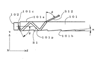
携帯電話機、ノートパソコン等に用にいられる液晶表示装置(LCD)のようなフラットパネルディスプレーには、一般に、そのフラットパネルを照らすための背景システムとしてのバックライトが組み合わせて使用されている。このバックライトの重要な要件は LCDパネル等のフラットパネルの全表面にわたって、均等でかつ十分に強い光分布を与えることである。このために、図8に示すような導光板とプリズムシートを用いたバックライトが従来から知られている(例えば、特許文献1参照)。
ここで、図8(a)はかかる従来のバックライト110の斜視図、図8(b)はその上面図、図8(c)バックライト110をその幅方向(Xの方向)から見た側面図である。図8に示す直交座標のX、Y、Zの方向は、それぞれバックライト110の幅方向、厚さ方向、長さ方向、を示している。図8において、101は導光板、102は導光板の1の側面である入光面101cに対向する位置に配された発光源としてのLED(発光ダイオード)、103は導光板101の上面101aに対向して配されたプリズムシート、104は導光板101の下面101bに対向して配された反射シートである。導光板101の上面101aは滑らかな平面となっており、その下面101bには比較的小さな傾斜角(図9のα)でZ方向に向けて立ち上がるように傾斜するプリズム面を有する複数のプリズム101pが形成されている。一方、プリズムシート103の導光板101に対向する下面103bには鋭角(例えば60°〜75°)に突起した複数のプリズム103pが形成されている。以下に、前記のバックライト110の作用を説明する。
8A is a perspective view of such a conventional backlight 110, FIG. 8B is a top view thereof, and FIG. 8C is a side view of the backlight 110 viewed from the width direction (direction X). FIG. The directions of X, Y, and Z in the orthogonal coordinates shown in FIG. 8 indicate the width direction, the thickness direction, and the length direction of the backlight 110, respectively. In FIG. 8, 101 is a light guide plate, 102 is an LED (light emitting diode) as a light emitting source disposed at a position facing a light incident surface 101c which is one side surface of the light guide plate, and 103 is an upper surface 101a of the
次に、図9は前記導光板101の作用を示す図である。図9に示すように、LED102から導光板101の入光面101cに角度θで入射した光束S1は屈折により、θよりも小さい出射角で導光板101内に入り、その下面のプリズム101pの面に入射する。ここで光束S1は平行光線の束であるとする。このとき、プリズム101p面に対する入射角が臨界角(例えば導光板101の屈折率が1.55のときは40°)よりも大きな場合は、光束S1はここで反射され、導光板101の上面101aに入射する。ここで、上面101aに対する入射角が臨界角以下であれば、屈折により上面101aを透過して外部に出射するが、入射角が臨界角以上の場合は、図に示すように、更にここで反射されて下面101bのプリズム101p面に入射する。ここで、プリズム101pに傾斜角αがあるため、プリズム101p面で反射を受ける度に、その反射光として前記上面101aに入射する光束S1入射角は減少する(2αずつ)。このため、下面のプリズム101p面で1回又は複数回反射された後には、上面101aに対する入射角は臨界角以下となり、図9に例示するように上面101aを屈折により透過し、出射角φの光束S12として外部に出射することとなる。
ここで、傾斜角αは導光板101内部の光の伝播性を良くするために、小さな角度に設定される場合が多い。この場合、上面101aに対する入射角は臨界角以下となる場合でも、入射角は臨界角に近い角度になる。よって、前記の出射角φは大きな角度(例えば60°を超えるような角度)となりやすい。
Next, FIG. 9 is a diagram illustrating the operation of the
Here, the inclination angle α is often set to a small angle in order to improve the light propagation property inside the
図10は、図9に示すような導光板101の上面101aからの出射光の指向性を示す図であり、図10(a)はZY面における指向性を示し、図10(b)はXY面における指光性を示す図である。図10より総合的に見て、出射光の成分はZ方向に偏っており、
Y方向の成分が少なく、垂直方向の成分が少ないので、このままでは被照明体であるLCDパネル等に対し、照明に有効な垂直方向の照明光の成分を十分に供給することができず、バックライトとして必要な照明の明るさを得ることが困難となる。そこで、導光板101からの出射光をY方向に向けるためにプリズムシート103が配されている。
FIG. 10 is a diagram showing the directivity of light emitted from the upper surface 101a of the
Since the component in the Y direction is small and the component in the vertical direction is small, the vertical illumination light component effective for illumination cannot be sufficiently supplied to the LCD panel or the like to be illuminated as it is. It becomes difficult to obtain the brightness of illumination necessary for the light. Therefore, a prism sheet 103 is disposed in order to direct light emitted from the
なお、導光板の下面のプリズム101pの面に直接または上面101aからの反射を経て入射する内部光(S1)の入射角が臨界角よりも小となる場合がある。この場合は、図示は省略するが、入射光はプリズム101pの面を屈折により透過して、反射シート104(図8参照)に達し、ここで反射されて、プリズム101pの面を再び透過して導光板101内に入射する。このようにして、導光板101内の内部光の利用効率を高めることができる。
The incident angle of the internal light (S1) incident on the surface of the prism 101p on the lower surface of the light guide plate directly or through reflection from the upper surface 101a may be smaller than the critical angle. In this case, although illustration is omitted, incident light passes through the surface of the prism 101p by refraction, reaches the reflection sheet 104 (see FIG. 8), is reflected here, and passes through the surface of the prism 101p again. The light enters the
以下に、プリズムシート103の作用につき説明する。図11はプリズムシート103の作用を示す図である。図11に示すようにZY面で見れば導光板の上面101aから出射した光束S12は、プリズムシート103の導光板101に対向する下面に設けられたプリズム103pのプリズム斜面103paに垂直に近い角度で(0°に近い入射角で)入射し、ほとんど屈折することなくプリズムシート103内を進行してプリズムの稜線を挟んで反対側の斜面103pbに入射し、ここで全反射され、略鉛直方向(Y方向)に上方に進行し、プリズムシート103の上面103aからほとんど屈折することなく照明光束13として出射する。ここで最終出射面であるプリズムシートの上面103aは平滑面または簡素な粗面になっている。このように、導光板からの出射光の光束S12は,ほとんどそのまま(平行光線の束として)プリズムシート103で反射されて方向を変えるだけなので、最終的な出射光であるバックライトとしての照明用光束S13はほとんど平行光による光束であり、かかる光束が集合したバックライトの照明光は、バックライトの長さ方向(Z方向)の指向性が狭い。また、最終出射面が簡素な粗面になっている場合でもZ方向の指向性は若干しか広がらない。
Hereinafter, the operation of the prism sheet 103 will be described. FIG. 11 is a diagram illustrating the operation of the prism sheet 103. As shown in FIG. 11, when viewed in the ZY plane, the light beam S12 emitted from the upper surface 101a of the light guide plate is at an angle close to perpendicular to the prism slope 103pa of the prism 103p provided on the lower surface of the prism sheet 103 facing the
ここで、図12は前記バックライトの照明光の指向性を示す図であり、図12(a)はZY面における指向性を示し、図12(b)はXY面における指向性を示す。図12からもわかるように、バックライトの指向性はY方向に関してはその成分が大きく、図示しないフラットパネルに効果的に入射する光量を上げ、全体的な照明の明るさを上げることについては有利となる。しかし、図12(a)に示すZ方向の指向性の幅が、図12(b)に示すX方向の指向性の幅に比してかなり小さくなり、均質な照明をすることを妨害する。(例えば、明暗の縞模様等を生ずる場合がある。)この結果、照明の品位が低下するという問題を生ずる。 Here, FIG. 12 is a diagram showing the directivity of the illumination light of the backlight, FIG. 12 (a) shows the directivity on the ZY plane, and FIG. 12 (b) shows the directivity on the XY plane. As can be seen from FIG. 12, the directivity of the backlight has a large component in the Y direction, which is advantageous for increasing the amount of light that effectively enters a flat panel (not shown) and increasing the overall illumination brightness. It becomes. However, the directivity width in the Z direction shown in FIG. 12 (a) is considerably smaller than the directivity width in the X direction shown in FIG. 12 (b), which hinders uniform illumination. (For example, a bright and dark stripe pattern may occur.) As a result, there arises a problem that the quality of illumination deteriorates.
本発明は上記したような、発光源と、導光板と、導光板に対向するプリズム面を備えたプリズムシートとを有するバックライトにおける照明光の指向性の問題すなわち、バックライトの照明光の指向性が方向によって大きな差異を生じ、均質な照明をすることを妨害し、照明の品位が低下するという問題を改善することを課題とする。 The present invention has the above-described problem of directivity of illumination light in a backlight having a light source, a light guide plate, and a prism sheet having a prism surface facing the light guide plate, that is, directivity of illumination light of the backlight. It is an object of the present invention to improve the problem that the quality is greatly different depending on the direction, obstructs uniform illumination, and the quality of the illumination is deteriorated.
上記の課題を解決するための第1の手段として本発明は、導光板と、その導光板の1つの側面である入光面に対向して配された発光源と、前記導光板の上面に対向する位置に配されたプリズムシートと、前記導光板の下面に対向する位置に配された反射シートとを有し、前記発光源から前記入光面を経て前記導光板に入光した光線を導光板により光路変換してその上面より、前記プリズムシートに入射し、そのプリズムシートにより光線の方向を整えて被照明体に照明光を出射するバックライトにおいて、前記プリズムシートは最終出射面にレンチキュラーレンズを設けたことを特徴とする。 As a first means for solving the above-described problems, the present invention provides a light guide plate, a light emitting source disposed facing a light incident surface that is one side surface of the light guide plate, and an upper surface of the light guide plate. A prism sheet disposed at an opposing position; and a reflection sheet disposed at a position facing the lower surface of the light guide plate; and a light beam incident on the light guide plate from the light emitting source through the light incident surface. In a backlight in which the light path is changed by a light guide plate and incident on the prism sheet from the upper surface thereof, and the direction of the light beam is adjusted by the prism sheet and the illumination light is emitted to the illuminated body, the prism sheet is lenticular on the final emission surface A lens is provided.
上記の課題を解決するための第2の手段として本発明は、前記第1の手段において、前記プリズムシートは導光板と対向する面にプリズムを設け、その反対側の最終出射面にレンチキュラーレンズを設けてなり、前記プリズムの稜線と前記レンチキュラーレンズの稜線は互いに略平行であることを特徴とする。 As a second means for solving the above-mentioned problems, in the first means, the present invention provides the prism sheet, wherein the prism sheet is provided with a prism on a surface facing the light guide plate, and a lenticular lens is disposed on a final exit surface on the opposite side. The ridge line of the prism and the ridge line of the lenticular lens are substantially parallel to each other.
上記の課題を解決するための第3の手段として本発明は、前記第2の手段において、 前記プリズムシートのプリズムの稜線の方向およびレンチキュラーレンズの稜線の方向は前記導光板の入光面の方向と略平行であることを特徴とする。 As a third means for solving the above-mentioned problems, the present invention provides the second means, wherein the direction of the ridge line of the prism of the prism sheet and the direction of the ridge line of the lenticular lens are directions of the light incident surface of the light guide plate. It is characterized by being substantially parallel to.
上記の課題を解決するための第4の手段として本発明は、前記第1の手段乃至第3の手段のいずれかにおいて、導光板の下面には稜線が入光面に略平行なプリズムが設けられていることを特徴とする。 As a fourth means for solving the above-mentioned problems, in the present invention, in any one of the first to third means, a prism whose ridgeline is substantially parallel to the light incident surface is provided on the lower surface of the light guide plate. It is characterized by being.
上記の課題を解決するための第5の手段として本発明は、バックライトに使用されるプリズムシートにおいて、一方の面にプリズムが設けられ、これと対向する他方の面にレンチキュラーレンズが設けられていることを特徴とする。 As a fifth means for solving the above problems, the present invention provides a prism sheet used in a backlight, wherein a prism is provided on one surface and a lenticular lens is provided on the other surface opposite to the prism. It is characterized by being.
前記第1の手段乃至第4の手段に係るバックライトのいずれかにおいては、バックライトの導光板からプリズムシートのプリズム面で主として反射されて、プリズムシートの垂直方向に向かう光は、プリズムシートの最終出射面に形成されたレンズにより、集光(凸レンズの場合)又は発散(凹レンズの場合)され、バックライトの長さ方向(導光板の入光面に垂直な方向)の指向性を広げることができる。このため、バックライトの長さ方向と幅方向の指向性を同じにし、照明品位の高いバックライトを構成することができる。 In any one of the backlights according to the first to fourth means, light reflected mainly from the prism surface of the prism sheet from the light guide plate of the backlight and directed in the vertical direction of the prism sheet is transmitted to the prism sheet. The directivity in the length direction of the backlight (perpendicular to the light incident surface of the light guide plate) is expanded by condensing (in the case of a convex lens) or diverging (in the case of a concave lens) by the lens formed on the final emission surface. Can do. For this reason, the directivity of the length direction of a backlight and the directivity of the width direction can be made the same, and a backlight with high illumination quality can be comprised.
前記第5の手段に係るプリズムシートをバックライトに使用することにより、上記(段落13)と同様の原理により、照明品位の高いバックライトを構成することができる。 By using the prism sheet according to the fifth means for the backlight, a backlight with high illumination quality can be configured based on the same principle as described above (paragraph 13).
導光板と、その導光板の1の側面である入光面に対向して配されたLEDと、前記導光板の上面に対向する位置に配されたプリズムシートとを有し、前記LED光源から前記入光面を経て前記導光板に入光した光線を導光板により光路変換してその上面より、前記プリズムシートに入射し、そのプリズムシートにより光線の方向を整えて被照明体に照明光を出射するバックライトにおいて、前記プリズムシートを導光板と対向する側にプリズムを設け、プリズムと反対側の最終出射面にレンチキュラーレンズを設けた構成とする。 A light guide plate, an LED disposed opposite to a light incident surface that is one side surface of the light guide plate, and a prism sheet disposed at a position facing the upper surface of the light guide plate; The light beam that has entered the light guide plate through the light incident surface is converted into an optical path by the light guide plate, and is incident on the prism sheet from the upper surface thereof. In the outgoing backlight, the prism sheet is provided with a prism on the side facing the light guide plate, and a lenticular lens is provided on the final outgoing surface opposite to the prism.
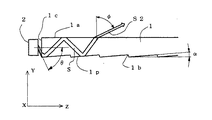
以下に図面を参照して、本発明に係るバックライトの実施例1を説明する。図1は本実施例1に係るバックライト10の構成を示す図であり、図1(a)はバックライト10の斜視図、図1(b)はその上面図、図1(c)バックライト10をその幅方向(Xの方向)から見た側面図である。図1に示す直交座標のX、Y、Zの方向は、それぞれバックライト10の幅方向、厚さ方向、長さ方向を示している。そして、図1(d)は図1(c)のA部の拡大図である。図1において、1は導光板、2は導光板1の1つの側面である入光面1cに対向する位置に配された発光源としてのLED(発光ダイオード)、3は導光板1の上面1aに対向して配されたプリズムシート、4は導光板1の下面1bに対向して配された反射シートである。導光板1は透明なプラスチックよりなり、その上面1aは滑らかな平面となっており、その下面1bには比較的小さな傾斜角(図2のα参照)でZ方向に向けて立ち上がるように傾斜するプリズム面を有する複数のプリズム1pが形成されている。一方、プリズムシート3も透明なプラスチックよりなり、その導光板1に対向する下面3bには鋭角(例えば60°〜75°)に突起した複数のプリズム3pが形成されている。そして、プリズムシート3の前記プリズム3pが形成された下面3bの反対側の上面3aには複数の凸状のレンチキュラーレンズ3Lが形成されている(図1(d)参照)。この凸状のレンチキュラーレンズ3Lの面は後述するようにバックライトの照明光の最終出射面となる。
ここでプリズム3pの稜線と前記レンチキュラーレンズ3Lの稜線(又は母線)の方向は、図1(a)、図1(b)に示すようにともにX方向に向かい、互いに平行となっている。なお、前記の導光板1の下面1bのプリズム1pの稜線の方向もX方向となっている。以下に、図1に示すバックライト10の作用を説明する。
Here, the directions of the ridge line of the prism 3p and the ridge line (or bus line) of the lenticular lens 3L are both parallel to each other in the X direction as shown in FIGS. 1 (a) and 1 (b). The direction of the ridge line of the prism 1p on the lower surface 1b of the
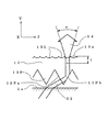
図2および図3は導光板1の作用を示す図である。図2に示すように、LED2から導光板1の入光面1cに角度θで入射した光束Sは屈折により、θよりも小さい出射角で導光板1内に入り、その下面のプリズム1pの面に入射する。ここで光束Sは平行光線の束であるとする。このように導光板1に入射した後は、光束Sはすでに従来例において図9を用いて説明したのと同様の原理により、下面のプリズム1pで反射されるごとに入射角が減少し、上面1aに対する入射角が臨界角(例えば導光板1の屈折率が1.55のときは40°)以下となったとき、はじめて、この面を屈折により透過して、かなり大きな出射角φ(例えば60°以上)の光束S2として外部に出射する。
2 and 3 are diagrams illustrating the operation of the
図3は、この導光板の作用を、上記の光束Sに含まれる1本の光線sについて、更に詳しく説明するための図である。図3に示すように、光線sはLED2から導光板1の入光面1cに角度θで入射し、ここで屈折され、スネルの法則により、屈折率n=1.55のときは、
θ1=sin−1[(sinθ)/1.55]・・・・(1)
と、入射角θよりもかなり小さな角度θ1で導光板1内に出射し、αの傾斜角を有するプリズムp1の面に、入射角 φ1p=90°―θ1―α の角度で入射する。ここで入射角φ1pが臨界角以上であれば、光線は全反射されて導光板の上面1aに入射角
φ1a=90°―θ1―2α で入射する。ここで、入射角φ1aが臨界角以上であれば、光線sは下面のプリズム1pに向け、更に反射され、下面のプリズム1pに対し入射角
φ2p=90°―θ1―3α で入射する。このようにして、導光板の下面のプリズム1pにおいて1回反射を受けるごとに上面1aへの入射角は2αずつ減少する。すなわち、プリズム1pで、n回反射を受けた場合の上面1aに対する入射角をφnaとすれば、
φna=90°―β―2nα・・・・(2)
と表すことができる。すなわち、反射を繰り返すたびに入射角が減少し、臨界角以下となることができる。そしてこのとき上面1aを透過して図2に例示するφの出射角で外部に出射する。
FIG. 3 is a diagram for explaining the operation of the light guide plate in more detail with respect to one light beam s included in the light beam S described above. As shown in FIG. 3, the light beam s enters the light incident surface 1c of the
θ1 = sin −1 [(sin θ) /1.55] (1)
Then, the light is emitted into the
φna = 90 ° -β-2nα (2)
It can be expressed as. That is, the incident angle decreases each time reflection is repeated, and can be equal to or less than the critical angle. At this time, the light passes through the upper surface 1a and is emitted to the outside at an emission angle of φ illustrated in FIG.
例えば、θ1=30° α=6° 臨界角=40° としたとき、下面のプリズム1pにおいて1回反射を受けた場合は(2)式より、上面1aに対する入射角は
φ1a=60°―12°=48° となり、臨界角以上となり、反射されるが、プリズム1pにおいて2回反射を受けた場合は、上面1aに対する入射角は
φ2a=60°―24°=36° となり、臨界角40°以下となるので、入射光は屈折により、図2に示すように出射角φで上面1aを透過して出射する。この場合入射角であるφ2aは臨界角に近いので、図2に示す出射光S2の出射角φは大となり、例えば60°以上となる。よって、導光板1からの出射光S2の指向性は、従来と同様に、図10に示すようにY成分が少なくZ成分に偏ったものとなる。
For example, when θ1 = 30 °, α = 6 °, and critical angle = 40 °, when the lower surface prism 1p receives a single reflection, the incident angle with respect to the upper surface 1a is φ1a = 60 ° −12 from equation (2). ° = 48 °, which is greater than the critical angle and is reflected, but when it is reflected twice by the prism 1p, the incident angle with respect to the upper surface 1a is φ2a = 60 ° −24 ° = 36 °, and the critical angle is 40 °. Therefore, the incident light is refracted and is transmitted through the upper surface 1a at an emission angle φ as shown in FIG. In this case, since the incident angle φ2a is close to the critical angle, the outgoing angle φ of the outgoing light S2 shown in FIG. 2 becomes large, for example, 60 ° or more. Therefore, the directivity of the outgoing light S2 from the
次に、反射シート4(図1参照)は導光板の下面1bのプリズム1pのプリズム面に内側から入射する光の入射角が臨界角以内である場合にこの面を透過して下方に出射する光を反射して、プリズム面を透過して再び導光板1内に入光させ、光の利用効率を高める作用をする。
以上に述べた、導光板1および反射シート4の作用原理そのものは、すでに、図8、図9に示して説明した従来のバックライト110の場合と同様であり、公知のものであるが、本実施例1を説明するための順序として述べたものである。
Next, the reflection sheet 4 (see FIG. 1) passes through this surface and emits downward when the incident angle of light incident on the prism surface of the prism 1p on the lower surface 1b of the light guide plate is within the critical angle. The light is reflected, passes through the prism surface, and enters the
The principle of operation of the
図4は本実施例1に係るバックライト(10)におけるプリズムシート3の作用を示す図である。図4に示すように、導光板1の上面1aを出射角φ(図2参照)で出射した光束S2はプリズムシート3の下面3bにおいて導光板1に対向する位置に設けられたプリズム3pの左側の斜面3paに入射する。この場合、プリズム3pの頂角が出射角φに対応した所定の角度範囲にあれば、プリズムの左側の斜面3paには90°付近の入射角で入射し、ほとんど屈折することなく、プリズム3p内を進行し、その右側の斜面3pbに入射し、ここで全反射され、上方に略垂直方向(Y方向)に進行し、プリズムシート3の上面3aに形成された凸状のレンチキュラーレンズ3Lに達し、レンチキュラーレンズ3Lの面を屈折により透過して外部に出射する。このレンチキュラーレンズ3Lは図の面内(ZY面)では上に凸に湾曲し、紙面に垂直方向(X方向)にはその湾曲を保った状態で真っ直ぐに伸びている。最終出射面であるレンチキュラーレンズ3Lを出射した光線は屈折により一旦、レンズの焦点距離fだけ離れた位置に集光した後、集光の際の角度に略等しい角度ωをもってZY面においてZ方向に拡散し、最終的な照明光束S3となる。このように拡散する照明光束S3の存在により、バックライト10の照明光の指向性が改善される。この様子を指向性の特性図である図5を用いて説明する。本実施例1に係るバックライト10によれば、図5(a)に示すように、の照明光のZY面におけるZ方向の指向性の幅を従来(図12(a)参照)よりも広げることができる。
FIG. 4 is a diagram illustrating the operation of the
一方、レンチキュラーレンズ3Lからの出射光は、図の面に垂直な方向(X方向)においては、レンチキュラーレンズ3Lの面は湾曲していないので、レンズによる集光、拡散作用は行われない。よって本実施例1に係るバックライトのXY面におけるX方向の指向性の幅は図5(b)に示すように従来(図12(b)参照)と変わらないことになる。この結果、本実施例1においてはバックライトのZ方向(長さ方向)の指向性とX方向(幅方向)の指向性の大きさを略等しくすることができ、照明品位の高いバックライトを実現することができる。なお、バックライトのZ方向の指向性はレンチキュラーレンズ3Lの曲率を変えて、焦点距離を変えることにより、拡散角ωを変えることにより調整することができるので、Z方向(長さ方向)の指向性とX方向(幅方向)の指向性の大きさを完全に等しくしたり、目的に応じて、所望の比率とすることもできる。 On the other hand, the light emitted from the lenticular lens 3L is not focused or diffused by the lens because the surface of the lenticular lens 3L is not curved in the direction (X direction) perpendicular to the plane of the drawing. Therefore, the directivity width in the X direction on the XY plane of the backlight according to the first embodiment is not different from the conventional one (see FIG. 12B) as shown in FIG. As a result, in the first embodiment, the directivity in the Z direction (length direction) and the directivity in the X direction (width direction) of the backlight can be made substantially equal, and a backlight with high illumination quality can be obtained. Can be realized. The directivity in the Z direction of the backlight can be adjusted by changing the diffusion angle ω by changing the focal length by changing the curvature of the lenticular lens 3L, so that the directivity in the Z direction (length direction). The directivity in the X direction (width direction) can be made completely equal, or a desired ratio can be set according to the purpose.
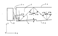
以下に図面を参照して、本発明に係るバックライトの実施例2を説明する。図6は本実施例2に係るバックライト20の構成を示す図であり、図6(a)はその上面図、図6(b)は直交座標X、Y、ZのX方向から見た側面図、図6(c)は図6(b)のB部の拡大図である。図6において13はプリズムシートである。プリズムシート13は透明なプラスチックよりなり、その導光板1に対向する下面13bには図1に示したバックライト10のプリズムシート3の下面に設けられたプリズム3pと同様の複数のプリズム13pが形成されている。そして、プリズムシート13の前記プリズム13pが形成された下面13bの反対側の上面13aには複数の凹状のレンチキュラーレンズ13Lが形成されている。ここでプリズム13pの稜線と前記レンチキュラーレンズ13Lの稜線(又は長手方向)は共にX方向に伸び、互いに平行となっている。なお、本実施例2に係るバックライト20のプリズムシート13以外の部材およびその記号は図1に示した実施例1に係るバックライト10の場合と同様である。すなわち、本実施例2において、導光板1および反射シート4の作用はすでに述べた実施例1の場合と同様である。そこで、前記のプリズムシート13の作用につき特に説明を行う。
図7は本実施例2に係るバックライト(20)におけるプリズムシート13の作用を示す図である。図7に示すように、導光板1の上面1aを出射角φ(図2参照)で出射した光束S2はプリズムシート13の下面13bにおいて導光板1に対向する位置に設けられたプリズム13pの左側の斜面13paに入射し、すでに実施例1において説明したのと同様にして右側の斜面13pbで反射されて上方に略垂直方向(Y方向)に進行し、プリズムシート13の上面13aに形成された凹状のレンチキュラーレンズ13Lに達し、最終出射面であるレンチキュラーレンズ13Lの面を屈折により透過して外部に出射する。このレンチキュラーレンズ13Lは図の面内(ZY面)では下に凸に凹状に湾曲し、紙面に垂直方向(X方向)にはその湾曲を保った状態で真っ直ぐに伸びている。レンチキュラーレンズ13Lを出射した光線は凹レンズの屈折により、ZY面においては、レンズの表面から略焦点距離fだけ内側の位置が仮想的な光源となるような方向に拡散角ωをもってZ方向に拡散し、最終的な照明光束S4となる。これにより、バックライト20の最終出射光の指向性はZ方向の幅が従来より増加し、X方向の指向性の幅とのバランスがとれ、図5に示したバックライト10の指向性と同様となり、照明の品位が向上する。
FIG. 7 is a diagram illustrating the action of the
1 導光板
1a、3a、13a 上面
1b、3b、13b 下面
1c 入光面
1p、3p、13p プリズム
2 LED
3、13 プリズムシート
3L、13L レンチキュラーレンズ
4 反射シート
S 光束
S2 出射光
s 光線
S3、S4 照明光束
1 Light guide plate 1a, 3a, 13a Upper surface 1b, 3b, 13b Lower surface 1c Light incident surface 1p, 3p,
3, 13 Prism sheet 3L,
Claims (5)
A prism sheet used for a backlight, wherein a prism is provided on one surface, and a lenticular lens is provided on the other surface opposite to the prism.
Priority Applications (5)
| Application Number | Priority Date | Filing Date | Title |
|---|---|---|---|
| JP2004035837A JP4262113B2 (en) | 2004-02-13 | 2004-02-13 | Backlight |
| KR1020050011154A KR100801227B1 (en) | 2004-02-13 | 2005-02-07 | Backlight |
| CN2005100082619A CN100406995C (en) | 2004-02-13 | 2005-02-07 | Backlight system |
| US11/055,018 US7046907B2 (en) | 2004-02-13 | 2005-02-11 | Backlight system |
| DE102005006586.4A DE102005006586B4 (en) | 2004-02-13 | 2005-02-14 | Backlighting system |
Applications Claiming Priority (1)
| Application Number | Priority Date | Filing Date | Title |
|---|---|---|---|
| JP2004035837A JP4262113B2 (en) | 2004-02-13 | 2004-02-13 | Backlight |
Publications (2)
| Publication Number | Publication Date |
|---|---|
| JP2005228584A JP2005228584A (en) | 2005-08-25 |
| JP4262113B2 true JP4262113B2 (en) | 2009-05-13 |
Family
ID=34879222
Family Applications (1)
| Application Number | Title | Priority Date | Filing Date |
|---|---|---|---|
| JP2004035837A Expired - Fee Related JP4262113B2 (en) | 2004-02-13 | 2004-02-13 | Backlight |
Country Status (5)
| Country | Link |
|---|---|
| US (1) | US7046907B2 (en) |
| JP (1) | JP4262113B2 (en) |
| KR (1) | KR100801227B1 (en) |
| CN (1) | CN100406995C (en) |
| DE (1) | DE102005006586B4 (en) |
Families Citing this family (168)
| Publication number | Priority date | Publication date | Assignee | Title |
|---|---|---|---|---|
| US8645137B2 (en) | 2000-03-16 | 2014-02-04 | Apple Inc. | Fast, language-independent method for user authentication by voice |
| US8677377B2 (en) | 2005-09-08 | 2014-03-18 | Apple Inc. | Method and apparatus for building an intelligent automated assistant |
| US7486854B2 (en) * | 2006-01-24 | 2009-02-03 | Uni-Pixel Displays, Inc. | Optical microstructures for light extraction and control |
| US9318108B2 (en) | 2010-01-18 | 2016-04-19 | Apple Inc. | Intelligent automated assistant |
| JP2009003412A (en) * | 2007-03-07 | 2009-01-08 | Rohm & Haas Denmark Finance As | Polarization turning film with reduced color separation |
| US8977255B2 (en) | 2007-04-03 | 2015-03-10 | Apple Inc. | Method and system for operating a multi-function portable electronic device using voice-activation |
| US9337373B2 (en) | 2007-05-01 | 2016-05-10 | Morgan Solar Inc. | Light-guide solar module, method of fabrication thereof, and panel made therefrom |
| US9040808B2 (en) * | 2007-05-01 | 2015-05-26 | Morgan Solar Inc. | Light-guide solar panel and method of fabrication thereof |
| US8152339B2 (en) | 2007-05-01 | 2012-04-10 | Morgan Solar Inc. | Illumination device |
| US8412010B2 (en) | 2007-09-10 | 2013-04-02 | Banyan Energy, Inc. | Compact optics for concentration and illumination systems |
| US7672549B2 (en) * | 2007-09-10 | 2010-03-02 | Banyan Energy, Inc. | Solar energy concentrator |
| WO2009035986A2 (en) * | 2007-09-10 | 2009-03-19 | Banyan Energy, Inc | Compact optics for concentration, aggregation and illumination of light energy |
| US10002189B2 (en) | 2007-12-20 | 2018-06-19 | Apple Inc. | Method and apparatus for searching using an active ontology |
| US9330720B2 (en) | 2008-01-03 | 2016-05-03 | Apple Inc. | Methods and apparatus for altering audio output signals |
| US20110007512A1 (en) * | 2008-03-19 | 2011-01-13 | I2Ic Corporation | Directional Light Source Using Refractive and Reflective Optics |
| US8996376B2 (en) | 2008-04-05 | 2015-03-31 | Apple Inc. | Intelligent text-to-speech conversion |
| US7639918B2 (en) * | 2008-05-05 | 2009-12-29 | Visteon Global Technologies, Inc. | Manifold-type lightguide with reduced thickness |
| US20090315883A1 (en) * | 2008-06-19 | 2009-12-24 | 3M Innovative Properties Company | Autostereoscopic display with pixelated luminaire |
| US20100030549A1 (en) | 2008-07-31 | 2010-02-04 | Lee Michael M | Mobile device having human language translation capability with positional feedback |
| US8676904B2 (en) | 2008-10-02 | 2014-03-18 | Apple Inc. | Electronic devices with voice command and contextual data processing capabilities |
| US9959870B2 (en) | 2008-12-11 | 2018-05-01 | Apple Inc. | Speech recognition involving a mobile device |
| US10241752B2 (en) | 2011-09-30 | 2019-03-26 | Apple Inc. | Interface for a virtual digital assistant |
| US10706373B2 (en) | 2011-06-03 | 2020-07-07 | Apple Inc. | Performing actions associated with task items that represent tasks to perform |
| US10241644B2 (en) | 2011-06-03 | 2019-03-26 | Apple Inc. | Actionable reminder entries |
| US9858925B2 (en) | 2009-06-05 | 2018-01-02 | Apple Inc. | Using context information to facilitate processing of commands in a virtual assistant |
| US9431006B2 (en) | 2009-07-02 | 2016-08-30 | Apple Inc. | Methods and apparatuses for automatic speech recognition |
| US10553209B2 (en) | 2010-01-18 | 2020-02-04 | Apple Inc. | Systems and methods for hands-free notification summaries |
| US8682667B2 (en) | 2010-02-25 | 2014-03-25 | Apple Inc. | User profiling for selecting user specific voice input processing information |
| KR101064076B1 (en) | 2010-04-01 | 2011-09-08 | 엘지이노텍 주식회사 | Light unit and display device having therof |
| EP2633349A4 (en) | 2010-10-28 | 2014-11-12 | Banyan Energy Inc | Redirecting optics for concentration and illumination systems |
| US8885995B2 (en) | 2011-02-07 | 2014-11-11 | Morgan Solar Inc. | Light-guide solar energy concentrator |
| US9262612B2 (en) | 2011-03-21 | 2016-02-16 | Apple Inc. | Device access using voice authentication |
| US10057736B2 (en) | 2011-06-03 | 2018-08-21 | Apple Inc. | Active transport based notifications |
| US8994660B2 (en) | 2011-08-29 | 2015-03-31 | Apple Inc. | Text correction processing |
| US10134385B2 (en) | 2012-03-02 | 2018-11-20 | Apple Inc. | Systems and methods for name pronunciation |
| KR20140144217A (en) * | 2012-03-20 | 2014-12-18 | 쓰리엠 이노베이티브 프로퍼티즈 컴파니 | Structured optical film |
| US8328403B1 (en) | 2012-03-21 | 2012-12-11 | Morgan Solar Inc. | Light guide illumination devices |
| US9280610B2 (en) | 2012-05-14 | 2016-03-08 | Apple Inc. | Crowd sourcing information to fulfill user requests |
| US9721563B2 (en) | 2012-06-08 | 2017-08-01 | Apple Inc. | Name recognition system |
| US9547647B2 (en) | 2012-09-19 | 2017-01-17 | Apple Inc. | Voice-based media searching |
| KR200482441Y1 (en) * | 2012-12-27 | 2017-01-24 | 젠텍스 코포레이션 | Light system |
| JP2016508007A (en) | 2013-02-07 | 2016-03-10 | アップル インコーポレイテッド | Voice trigger for digital assistant |
| US9977779B2 (en) | 2013-03-14 | 2018-05-22 | Apple Inc. | Automatic supplementation of word correction dictionaries |
| US10572476B2 (en) | 2013-03-14 | 2020-02-25 | Apple Inc. | Refining a search based on schedule items |
| US9733821B2 (en) | 2013-03-14 | 2017-08-15 | Apple Inc. | Voice control to diagnose inadvertent activation of accessibility features |
| US9368114B2 (en) | 2013-03-14 | 2016-06-14 | Apple Inc. | Context-sensitive handling of interruptions |
| US10642574B2 (en) | 2013-03-14 | 2020-05-05 | Apple Inc. | Device, method, and graphical user interface for outputting captions |
| US10652394B2 (en) | 2013-03-14 | 2020-05-12 | Apple Inc. | System and method for processing voicemail |
| CN112230878A (en) | 2013-03-15 | 2021-01-15 | 苹果公司 | Context-sensitive handling of interrupts |
| WO2014144579A1 (en) | 2013-03-15 | 2014-09-18 | Apple Inc. | System and method for updating an adaptive speech recognition model |
| KR101759009B1 (en) | 2013-03-15 | 2017-07-17 | 애플 인크. | Training an at least partial voice command system |
| US10748529B1 (en) | 2013-03-15 | 2020-08-18 | Apple Inc. | Voice activated device for use with a voice-based digital assistant |
| CN105190607B (en) | 2013-03-15 | 2018-11-30 | 苹果公司 | Pass through the user training of intelligent digital assistant |
| WO2014197334A2 (en) | 2013-06-07 | 2014-12-11 | Apple Inc. | System and method for user-specified pronunciation of words for speech synthesis and recognition |
| WO2014197336A1 (en) | 2013-06-07 | 2014-12-11 | Apple Inc. | System and method for detecting errors in interactions with a voice-based digital assistant |
| US9582608B2 (en) | 2013-06-07 | 2017-02-28 | Apple Inc. | Unified ranking with entropy-weighted information for phrase-based semantic auto-completion |
| WO2014197335A1 (en) | 2013-06-08 | 2014-12-11 | Apple Inc. | Interpreting and acting upon commands that involve sharing information with remote devices |
| CN110442699A (en) | 2013-06-09 | 2019-11-12 | 苹果公司 | Operate method, computer-readable medium, electronic equipment and the system of digital assistants |
| US10176167B2 (en) | 2013-06-09 | 2019-01-08 | Apple Inc. | System and method for inferring user intent from speech inputs |
| CN105265005B (en) | 2013-06-13 | 2019-09-17 | 苹果公司 | System and method for the urgent call initiated by voice command |
| JP6163266B2 (en) | 2013-08-06 | 2017-07-12 | アップル インコーポレイテッド | Automatic activation of smart responses based on activation from remote devices |
| US10296160B2 (en) | 2013-12-06 | 2019-05-21 | Apple Inc. | Method for extracting salient dialog usage from live data |
| JP2015195181A (en) * | 2014-03-28 | 2015-11-05 | 大日本印刷株式会社 | Surface light source device and display device |
| US9620105B2 (en) | 2014-05-15 | 2017-04-11 | Apple Inc. | Analyzing audio input for efficient speech and music recognition |
| US10592095B2 (en) | 2014-05-23 | 2020-03-17 | Apple Inc. | Instantaneous speaking of content on touch devices |
| US9502031B2 (en) | 2014-05-27 | 2016-11-22 | Apple Inc. | Method for supporting dynamic grammars in WFST-based ASR |
| US10170123B2 (en) | 2014-05-30 | 2019-01-01 | Apple Inc. | Intelligent assistant for home automation |
| US9734193B2 (en) | 2014-05-30 | 2017-08-15 | Apple Inc. | Determining domain salience ranking from ambiguous words in natural speech |
| US9760559B2 (en) | 2014-05-30 | 2017-09-12 | Apple Inc. | Predictive text input |
| US9633004B2 (en) | 2014-05-30 | 2017-04-25 | Apple Inc. | Better resolution when referencing to concepts |
| US9430463B2 (en) | 2014-05-30 | 2016-08-30 | Apple Inc. | Exemplar-based natural language processing |
| US9842101B2 (en) | 2014-05-30 | 2017-12-12 | Apple Inc. | Predictive conversion of language input |
| US9785630B2 (en) | 2014-05-30 | 2017-10-10 | Apple Inc. | Text prediction using combined word N-gram and unigram language models |
| US9715875B2 (en) | 2014-05-30 | 2017-07-25 | Apple Inc. | Reducing the need for manual start/end-pointing and trigger phrases |
| US10078631B2 (en) | 2014-05-30 | 2018-09-18 | Apple Inc. | Entropy-guided text prediction using combined word and character n-gram language models |
| US9966065B2 (en) | 2014-05-30 | 2018-05-08 | Apple Inc. | Multi-command single utterance input method |
| US10289433B2 (en) | 2014-05-30 | 2019-05-14 | Apple Inc. | Domain specific language for encoding assistant dialog |
| US9338493B2 (en) | 2014-06-30 | 2016-05-10 | Apple Inc. | Intelligent automated assistant for TV user interactions |
| US10659851B2 (en) | 2014-06-30 | 2020-05-19 | Apple Inc. | Real-time digital assistant knowledge updates |
| US10446141B2 (en) | 2014-08-28 | 2019-10-15 | Apple Inc. | Automatic speech recognition based on user feedback |
| US9818400B2 (en) | 2014-09-11 | 2017-11-14 | Apple Inc. | Method and apparatus for discovering trending terms in speech requests |
| US10789041B2 (en) | 2014-09-12 | 2020-09-29 | Apple Inc. | Dynamic thresholds for always listening speech trigger |
| US9646609B2 (en) | 2014-09-30 | 2017-05-09 | Apple Inc. | Caching apparatus for serving phonetic pronunciations |
| US9886432B2 (en) | 2014-09-30 | 2018-02-06 | Apple Inc. | Parsimonious handling of word inflection via categorical stem + suffix N-gram language models |
| US10127911B2 (en) | 2014-09-30 | 2018-11-13 | Apple Inc. | Speaker identification and unsupervised speaker adaptation techniques |
| US9668121B2 (en) | 2014-09-30 | 2017-05-30 | Apple Inc. | Social reminders |
| US10074360B2 (en) | 2014-09-30 | 2018-09-11 | Apple Inc. | Providing an indication of the suitability of speech recognition |
| US10552013B2 (en) | 2014-12-02 | 2020-02-04 | Apple Inc. | Data detection |
| US9711141B2 (en) | 2014-12-09 | 2017-07-18 | Apple Inc. | Disambiguating heteronyms in speech synthesis |
| US10152299B2 (en) | 2015-03-06 | 2018-12-11 | Apple Inc. | Reducing response latency of intelligent automated assistants |
| US9865280B2 (en) | 2015-03-06 | 2018-01-09 | Apple Inc. | Structured dictation using intelligent automated assistants |
| US9721566B2 (en) | 2015-03-08 | 2017-08-01 | Apple Inc. | Competing devices responding to voice triggers |
| US10567477B2 (en) | 2015-03-08 | 2020-02-18 | Apple Inc. | Virtual assistant continuity |
| US9886953B2 (en) | 2015-03-08 | 2018-02-06 | Apple Inc. | Virtual assistant activation |
| US9899019B2 (en) | 2015-03-18 | 2018-02-20 | Apple Inc. | Systems and methods for structured stem and suffix language models |
| CN104730619A (en) * | 2015-03-27 | 2015-06-24 | 深圳市华星光电技术有限公司 | Light guide plate, backlight module with same and liquid crystal display |
| US9842105B2 (en) | 2015-04-16 | 2017-12-12 | Apple Inc. | Parsimonious continuous-space phrase representations for natural language processing |
| US10083688B2 (en) | 2015-05-27 | 2018-09-25 | Apple Inc. | Device voice control for selecting a displayed affordance |
| US10127220B2 (en) | 2015-06-04 | 2018-11-13 | Apple Inc. | Language identification from short strings |
| US9578173B2 (en) | 2015-06-05 | 2017-02-21 | Apple Inc. | Virtual assistant aided communication with 3rd party service in a communication session |
| US10101822B2 (en) | 2015-06-05 | 2018-10-16 | Apple Inc. | Language input correction |
| US10255907B2 (en) | 2015-06-07 | 2019-04-09 | Apple Inc. | Automatic accent detection using acoustic models |
| US10186254B2 (en) | 2015-06-07 | 2019-01-22 | Apple Inc. | Context-based endpoint detection |
| US11025565B2 (en) | 2015-06-07 | 2021-06-01 | Apple Inc. | Personalized prediction of responses for instant messaging |
| US10671428B2 (en) | 2015-09-08 | 2020-06-02 | Apple Inc. | Distributed personal assistant |
| US10747498B2 (en) | 2015-09-08 | 2020-08-18 | Apple Inc. | Zero latency digital assistant |
| US9697820B2 (en) | 2015-09-24 | 2017-07-04 | Apple Inc. | Unit-selection text-to-speech synthesis using concatenation-sensitive neural networks |
| US10366158B2 (en) | 2015-09-29 | 2019-07-30 | Apple Inc. | Efficient word encoding for recurrent neural network language models |
| US11010550B2 (en) | 2015-09-29 | 2021-05-18 | Apple Inc. | Unified language modeling framework for word prediction, auto-completion and auto-correction |
| US11587559B2 (en) | 2015-09-30 | 2023-02-21 | Apple Inc. | Intelligent device identification |
| US10691473B2 (en) | 2015-11-06 | 2020-06-23 | Apple Inc. | Intelligent automated assistant in a messaging environment |
| US10049668B2 (en) | 2015-12-02 | 2018-08-14 | Apple Inc. | Applying neural network language models to weighted finite state transducers for automatic speech recognition |
| US10223066B2 (en) | 2015-12-23 | 2019-03-05 | Apple Inc. | Proactive assistance based on dialog communication between devices |
| US10446143B2 (en) | 2016-03-14 | 2019-10-15 | Apple Inc. | Identification of voice inputs providing credentials |
| US9934775B2 (en) | 2016-05-26 | 2018-04-03 | Apple Inc. | Unit-selection text-to-speech synthesis based on predicted concatenation parameters |
| US9972304B2 (en) | 2016-06-03 | 2018-05-15 | Apple Inc. | Privacy preserving distributed evaluation framework for embedded personalized systems |
| US10249300B2 (en) | 2016-06-06 | 2019-04-02 | Apple Inc. | Intelligent list reading |
| US10049663B2 (en) | 2016-06-08 | 2018-08-14 | Apple, Inc. | Intelligent automated assistant for media exploration |
| DK179309B1 (en) | 2016-06-09 | 2018-04-23 | Apple Inc | Intelligent automated assistant in a home environment |
| US10067938B2 (en) | 2016-06-10 | 2018-09-04 | Apple Inc. | Multilingual word prediction |
| US10192552B2 (en) | 2016-06-10 | 2019-01-29 | Apple Inc. | Digital assistant providing whispered speech |
| US10490187B2 (en) | 2016-06-10 | 2019-11-26 | Apple Inc. | Digital assistant providing automated status report |
| US10586535B2 (en) | 2016-06-10 | 2020-03-10 | Apple Inc. | Intelligent digital assistant in a multi-tasking environment |
| US10509862B2 (en) | 2016-06-10 | 2019-12-17 | Apple Inc. | Dynamic phrase expansion of language input |
| DK201670540A1 (en) | 2016-06-11 | 2018-01-08 | Apple Inc | Application integration with a digital assistant |
| DK179343B1 (en) | 2016-06-11 | 2018-05-14 | Apple Inc | Intelligent task discovery |
| DK179415B1 (en) | 2016-06-11 | 2018-06-14 | Apple Inc | Intelligent device arbitration and control |
| DK179049B1 (en) | 2016-06-11 | 2017-09-18 | Apple Inc | Data driven natural language event detection and classification |
| US10474753B2 (en) | 2016-09-07 | 2019-11-12 | Apple Inc. | Language identification using recurrent neural networks |
| US10043516B2 (en) | 2016-09-23 | 2018-08-07 | Apple Inc. | Intelligent automated assistant |
| US11281993B2 (en) | 2016-12-05 | 2022-03-22 | Apple Inc. | Model and ensemble compression for metric learning |
| US10593346B2 (en) | 2016-12-22 | 2020-03-17 | Apple Inc. | Rank-reduced token representation for automatic speech recognition |
| US11204787B2 (en) | 2017-01-09 | 2021-12-21 | Apple Inc. | Application integration with a digital assistant |
| TWI597532B (en) * | 2017-04-28 | 2017-09-01 | 台達電子工業股份有限公司 | Backlight module and stereo display device using the same |
| US10417266B2 (en) | 2017-05-09 | 2019-09-17 | Apple Inc. | Context-aware ranking of intelligent response suggestions |
| DK201770383A1 (en) | 2017-05-09 | 2018-12-14 | Apple Inc. | User interface for correcting recognition errors |
| US10726832B2 (en) | 2017-05-11 | 2020-07-28 | Apple Inc. | Maintaining privacy of personal information |
| DK201770439A1 (en) | 2017-05-11 | 2018-12-13 | Apple Inc. | Offline personal assistant |
| US10395654B2 (en) | 2017-05-11 | 2019-08-27 | Apple Inc. | Text normalization based on a data-driven learning network |
| DK179745B1 (en) | 2017-05-12 | 2019-05-01 | Apple Inc. | SYNCHRONIZATION AND TASK DELEGATION OF A DIGITAL ASSISTANT |
| US11301477B2 (en) | 2017-05-12 | 2022-04-12 | Apple Inc. | Feedback analysis of a digital assistant |
| DK179496B1 (en) | 2017-05-12 | 2019-01-15 | Apple Inc. | USER-SPECIFIC Acoustic Models |
| DK201770429A1 (en) | 2017-05-12 | 2018-12-14 | Apple Inc. | Low-latency intelligent automated assistant |
| DK201770432A1 (en) | 2017-05-15 | 2018-12-21 | Apple Inc. | Hierarchical belief states for digital assistants |
| DK201770431A1 (en) | 2017-05-15 | 2018-12-20 | Apple Inc. | Optimizing dialogue policy decisions for digital assistants using implicit feedback |
| US10403278B2 (en) | 2017-05-16 | 2019-09-03 | Apple Inc. | Methods and systems for phonetic matching in digital assistant services |
| US10303715B2 (en) | 2017-05-16 | 2019-05-28 | Apple Inc. | Intelligent automated assistant for media exploration |
| US10311144B2 (en) | 2017-05-16 | 2019-06-04 | Apple Inc. | Emoji word sense disambiguation |
| DK179549B1 (en) | 2017-05-16 | 2019-02-12 | Apple Inc. | Far-field extension for digital assistant services |
| US10657328B2 (en) | 2017-06-02 | 2020-05-19 | Apple Inc. | Multi-task recurrent neural network architecture for efficient morphology handling in neural language modeling |
| US10445429B2 (en) | 2017-09-21 | 2019-10-15 | Apple Inc. | Natural language understanding using vocabularies with compressed serialized tries |
| US10755051B2 (en) | 2017-09-29 | 2020-08-25 | Apple Inc. | Rule-based natural language processing |
| US10636424B2 (en) | 2017-11-30 | 2020-04-28 | Apple Inc. | Multi-turn canned dialog |
| US10733982B2 (en) | 2018-01-08 | 2020-08-04 | Apple Inc. | Multi-directional dialog |
| US10733375B2 (en) | 2018-01-31 | 2020-08-04 | Apple Inc. | Knowledge-based framework for improving natural language understanding |
| US10789959B2 (en) | 2018-03-02 | 2020-09-29 | Apple Inc. | Training speaker recognition models for digital assistants |
| US10592604B2 (en) | 2018-03-12 | 2020-03-17 | Apple Inc. | Inverse text normalization for automatic speech recognition |
| US10818288B2 (en) | 2018-03-26 | 2020-10-27 | Apple Inc. | Natural assistant interaction |
| US10909331B2 (en) | 2018-03-30 | 2021-02-02 | Apple Inc. | Implicit identification of translation payload with neural machine translation |
| US11145294B2 (en) | 2018-05-07 | 2021-10-12 | Apple Inc. | Intelligent automated assistant for delivering content from user experiences |
| US10928918B2 (en) | 2018-05-07 | 2021-02-23 | Apple Inc. | Raise to speak |
| US10984780B2 (en) | 2018-05-21 | 2021-04-20 | Apple Inc. | Global semantic word embeddings using bi-directional recurrent neural networks |
| US10892996B2 (en) | 2018-06-01 | 2021-01-12 | Apple Inc. | Variable latency device coordination |
| DK179822B1 (en) | 2018-06-01 | 2019-07-12 | Apple Inc. | Voice interaction at a primary device to access call functionality of a companion device |
| DK201870355A1 (en) | 2018-06-01 | 2019-12-16 | Apple Inc. | Virtual assistant operation in multi-device environments |
| DK180639B1 (en) | 2018-06-01 | 2021-11-04 | Apple Inc | DISABILITY OF ATTENTION-ATTENTIVE VIRTUAL ASSISTANT |
| US11386266B2 (en) | 2018-06-01 | 2022-07-12 | Apple Inc. | Text correction |
| US10496705B1 (en) | 2018-06-03 | 2019-12-03 | Apple Inc. | Accelerated task performance |
Family Cites Families (14)
| Publication number | Priority date | Publication date | Assignee | Title |
|---|---|---|---|---|
| US5442482A (en) * | 1990-05-21 | 1995-08-15 | Johnson; William N. H. | Microlens screens, photopolymerisable materials and artifacts utilising the same |
| US5050946A (en) * | 1990-09-27 | 1991-09-24 | Compaq Computer Corporation | Faceted light pipe |
| US5428468A (en) * | 1993-11-05 | 1995-06-27 | Alliedsignal Inc. | Illumination system employing an array of microprisms |
| US5748828A (en) * | 1993-11-10 | 1998-05-05 | Alliedsignal Inc. | Color separating backlight |
| US5914760A (en) * | 1996-06-21 | 1999-06-22 | Casio Computer Co., Ltd. | Surface light source device and liquid crystal display device using the same |
| JP2001143515A (en) * | 1999-09-03 | 2001-05-25 | Mitsubishi Rayon Co Ltd | Prism sheet and panel light source element |
| JP3733418B2 (en) * | 2001-04-16 | 2006-01-11 | シャープ株式会社 | Adhesive sheet, laminated sheet and liquid crystal display device |
| KR20010079129A (en) * | 2001-06-15 | 2001-08-22 | 서대식 | Large area flat panel display using prism lens sheet |
| JP2003036713A (en) * | 2001-07-25 | 2003-02-07 | International Manufacturing & Engineering Services Co Ltd | Surface light source device |
| JP2003059321A (en) | 2001-08-13 | 2003-02-28 | Citizen Electronics Co Ltd | Flat light source illuminating object |
| JP4716397B2 (en) * | 2001-09-21 | 2011-07-06 | シチズン電子株式会社 | Flat lighting device |
| KR20030046047A (en) * | 2001-12-04 | 2003-06-12 | 주식회사 파인옵틱스 | Structure of light guide plate and fabrication methods using tilted and curved mono axis lens |
| JP2003262734A (en) * | 2002-03-08 | 2003-09-19 | Citizen Electronics Co Ltd | Light guide plate |
| JP3994190B2 (en) * | 2002-03-11 | 2007-10-17 | シチズン電子株式会社 | Backlight |
-
2004
- 2004-02-13 JP JP2004035837A patent/JP4262113B2/en not_active Expired - Fee Related
-
2005
- 2005-02-07 CN CN2005100082619A patent/CN100406995C/en not_active Expired - Fee Related
- 2005-02-07 KR KR1020050011154A patent/KR100801227B1/en active IP Right Grant
- 2005-02-11 US US11/055,018 patent/US7046907B2/en active Active
- 2005-02-14 DE DE102005006586.4A patent/DE102005006586B4/en not_active Expired - Fee Related
Also Published As
| Publication number | Publication date |
|---|---|
| JP2005228584A (en) | 2005-08-25 |
| CN1655032A (en) | 2005-08-17 |
| US7046907B2 (en) | 2006-05-16 |
| KR20060041800A (en) | 2006-05-12 |
| DE102005006586A1 (en) | 2005-10-27 |
| DE102005006586B4 (en) | 2016-04-28 |
| CN100406995C (en) | 2008-07-30 |
| KR100801227B1 (en) | 2008-02-05 |
| US20050191026A1 (en) | 2005-09-01 |
Similar Documents
| Publication | Publication Date | Title |
|---|---|---|
| JP4262113B2 (en) | Backlight | |
| US7275850B2 (en) | Backlight unit | |
| JP4011287B2 (en) | Light control sheet, surface light source device, and liquid crystal display | |
| JP5241068B2 (en) | Side light emitting device, backlight unit using the same as light source, and liquid crystal display device using the same | |
| KR101013532B1 (en) | Light guide plate | |
| US7911700B2 (en) | Light guiding film | |
| US7380971B2 (en) | Backlight module | |
| US7011442B2 (en) | Planar light source | |
| CN108692221B (en) | Light source module and prism sheet thereof | |
| JP2002196151A (en) | Light guide plate | |
| WO1998040664A1 (en) | Surface light source device and asymmetrical prism sheet | |
| JP2013161791A (en) | Light source module | |
| JP2002289023A (en) | Lighting device | |
| JP4421583B2 (en) | Light guide plate and surface light emitting device | |
| US7711223B2 (en) | Composite light guiding film module | |
| JP4645314B2 (en) | Light guide plate, edge light type surface light source and liquid crystal display device using the same | |
| US7674031B2 (en) | Optical film and backlight system using the same | |
| JP4014026B2 (en) | Surface light source device, image display device, and light guide plate | |
| TW200848663A (en) | Surface light-emitting device | |
| TW201426125A (en) | Light guide plate and backlight module | |
| US8403550B2 (en) | Surface light source device | |
| JP2005228718A (en) | Light guide plate | |
| JP4799488B2 (en) | Light emitting device, linear light emitting device, planar light emitting device, liquid crystal display device, and electronic apparatus | |
| JP2006134750A (en) | Backlight | |
| JP4349741B2 (en) | Illumination device having a light guide plate |
Legal Events
| Date | Code | Title | Description |
|---|---|---|---|
| A621 | Written request for application examination |
Free format text: JAPANESE INTERMEDIATE CODE: A621 Effective date: 20070118 |
|
| A977 | Report on retrieval |
Free format text: JAPANESE INTERMEDIATE CODE: A971007 Effective date: 20081218 |
|
| TRDD | Decision of grant or rejection written | ||
| A01 | Written decision to grant a patent or to grant a registration (utility model) |
Free format text: JAPANESE INTERMEDIATE CODE: A01 Effective date: 20090203 |
|
| A01 | Written decision to grant a patent or to grant a registration (utility model) |
Free format text: JAPANESE INTERMEDIATE CODE: A01 |
|
| A61 | First payment of annual fees (during grant procedure) |
Free format text: JAPANESE INTERMEDIATE CODE: A61 Effective date: 20090206 |
|
| FPAY | Renewal fee payment (event date is renewal date of database) |
Free format text: PAYMENT UNTIL: 20120220 Year of fee payment: 3 |
|
| R150 | Certificate of patent or registration of utility model |
Ref document number: 4262113 Country of ref document: JP Free format text: JAPANESE INTERMEDIATE CODE: R150 Free format text: JAPANESE INTERMEDIATE CODE: R150 |
|
| FPAY | Renewal fee payment (event date is renewal date of database) |
Free format text: PAYMENT UNTIL: 20120220 Year of fee payment: 3 |
|
| FPAY | Renewal fee payment (event date is renewal date of database) |
Free format text: PAYMENT UNTIL: 20150220 Year of fee payment: 6 |
|
| R250 | Receipt of annual fees |
Free format text: JAPANESE INTERMEDIATE CODE: R250 |
|
| R250 | Receipt of annual fees |
Free format text: JAPANESE INTERMEDIATE CODE: R250 |
|
| R250 | Receipt of annual fees |
Free format text: JAPANESE INTERMEDIATE CODE: R250 |
|
| R250 | Receipt of annual fees |
Free format text: JAPANESE INTERMEDIATE CODE: R250 |
|
| LAPS | Cancellation because of no payment of annual fees |