JP4261834B2 - Liquid bag, liquid bag mouth member and method of manufacturing the same - Google Patents
Liquid bag, liquid bag mouth member and method of manufacturing the same Download PDFInfo
- Publication number
- JP4261834B2 JP4261834B2 JP2002216825A JP2002216825A JP4261834B2 JP 4261834 B2 JP4261834 B2 JP 4261834B2 JP 2002216825 A JP2002216825 A JP 2002216825A JP 2002216825 A JP2002216825 A JP 2002216825A JP 4261834 B2 JP4261834 B2 JP 4261834B2
- Authority
- JP
- Japan
- Prior art keywords
- bag body
- liquid
- mouth
- bag
- opening
- Prior art date
- Legal status (The legal status is an assumption and is not a legal conclusion. Google has not performed a legal analysis and makes no representation as to the accuracy of the status listed.)
- Expired - Fee Related
Links
Images


Classifications
-
- A—HUMAN NECESSITIES
- A61—MEDICAL OR VETERINARY SCIENCE; HYGIENE
- A61M—DEVICES FOR INTRODUCING MEDIA INTO, OR ONTO, THE BODY; DEVICES FOR TRANSDUCING BODY MEDIA OR FOR TAKING MEDIA FROM THE BODY; DEVICES FOR PRODUCING OR ENDING SLEEP OR STUPOR
- A61M16/00—Devices for influencing the respiratory system of patients by gas treatment, e.g. mouth-to-mouth respiration; Tracheal tubes
- A61M16/10—Preparation of respiratory gases or vapours
- A61M16/14—Preparation of respiratory gases or vapours by mixing different fluids, one of them being in a liquid phase
- A61M16/16—Devices to humidify the respiration air
-
- A—HUMAN NECESSITIES
- A61—MEDICAL OR VETERINARY SCIENCE; HYGIENE
- A61M—DEVICES FOR INTRODUCING MEDIA INTO, OR ONTO, THE BODY; DEVICES FOR TRANSDUCING BODY MEDIA OR FOR TAKING MEDIA FROM THE BODY; DEVICES FOR PRODUCING OR ENDING SLEEP OR STUPOR
- A61M11/00—Sprayers or atomisers specially adapted for therapeutic purposes
- A61M11/06—Sprayers or atomisers specially adapted for therapeutic purposes of the injector type
-
- B—PERFORMING OPERATIONS; TRANSPORTING
- B29—WORKING OF PLASTICS; WORKING OF SUBSTANCES IN A PLASTIC STATE IN GENERAL
- B29C—SHAPING OR JOINING OF PLASTICS; SHAPING OF MATERIAL IN A PLASTIC STATE, NOT OTHERWISE PROVIDED FOR; AFTER-TREATMENT OF THE SHAPED PRODUCTS, e.g. REPAIRING
- B29C45/00—Injection moulding, i.e. forcing the required volume of moulding material through a nozzle into a closed mould; Apparatus therefor
- B29C45/14—Injection moulding, i.e. forcing the required volume of moulding material through a nozzle into a closed mould; Apparatus therefor incorporating preformed parts or layers, e.g. injection moulding around inserts or for coating articles
Landscapes
- Health & Medical Sciences (AREA)
- Engineering & Computer Science (AREA)
- General Health & Medical Sciences (AREA)
- Public Health (AREA)
- Anesthesiology (AREA)
- Biomedical Technology (AREA)
- Heart & Thoracic Surgery (AREA)
- Hematology (AREA)
- Life Sciences & Earth Sciences (AREA)
- Animal Behavior & Ethology (AREA)
- Veterinary Medicine (AREA)
- Pulmonology (AREA)
- Emergency Medicine (AREA)
- Manufacturing & Machinery (AREA)
- Mechanical Engineering (AREA)
- Bag Frames (AREA)
- Injection Moulding Of Plastics Or The Like (AREA)
- Packages (AREA)
- Medical Preparation Storing Or Oral Administration Devices (AREA)
- Containers And Packaging Bodies Having A Special Means To Remove Contents (AREA)
Description
【0001】
【発明の属する技術分野】
本発明は、液体バッグ、液体バッグ用口部材およびその製造方法に関し、特に、空気、酸素、窒素、二酸化炭素などの気体に水分(水蒸気または霧状の水)を付加する気体の水分付加器、具体的には酸素の湿潤器やネブライザー(噴霧器)として利用できる液体バッグに関する。
【0002】
【従来の技術及び発明が解決しようとする課題】
柔軟な熱可塑性樹脂製シートで構成されたバッグ本体を備えた従来の液体バッグとしては、下記の▲1▼▲2▼▲3▼のものが公知である。
▲1▼口部を一つ有する一つの口部材が封筒状のバッグ本体の周縁部の一部に封着された液体バッグ。
▲2▼口部を二つ有する一つの口部材が封筒状のバッグ本体の周縁部の一部に封着された液体バッグ(例えば、特開2000‐190997号公報等)。
▲3▼口部を一つ有する一つの口部材が封筒状のバッグ本体の周縁部の一部に封着されるとともに、バッグ本体の対面するシートの一部を特殊なヒートシール方法により熱溶着して内部を2部屋に区画した複室液体バッグ。この液体バッグは、一方の部屋を押圧することで2部屋に区画する溶着部が連通して各部屋に収納された液剤が混ざるように構成されている(例えば、特開平2‐4671号公報等)。
【0003】
ところで、酸素に水分(水蒸気または霧状の水)を付加して供給できる簡易酸素吸入器(湿潤器)としては、円筒状のハードボトルに酸素導入パイプを付属させたものが知られているが、使用時に無菌水を入れて用いるため、手間がかかり、衛生面でも問題があった。また、ハードボトルとしては、使い捨てのボックス状ハードボトルも使用されていたが、嵩高いため、製造装置がそれだけ大きくなり、製造コストが高く廃棄にも不便であった。そのため、柔軟な容器で構成された液体バッグにバブリング機能を付加することが考えられるが、前記▲1▼▲2▼▲3▼の液体バッグにバブリング機能を付加しようとすれば、気体をバッグ本体内に導入するためのチューブ等の他部材が必要であり、さらに▲1▼▲3▼ではポートの口部が一つであるため、バッグ本体内に導入した気体を外部に排出するための口部を有するポートがもう一つ必要となり、そうすれば部品点数が増加し、かつ製造工程も複雑となってコストアップとなる。
【0004】
そこで、本発明の主要な目的の一つは、部品点数が増加せず、シンプルな構成で、バブリングを可能とする液体バッグ、液体バッグ用口部材及びその製造方法を提供することである。
【0005】
【課題を解決するための手段】
本発明は、柔軟な熱可塑性樹脂製シートで構成された、液体を収納するバッグ本体と、このバッグ本体の周縁部の一部に封着された熱可塑性樹脂製口部材とを備え、
バッグ本体が、その周縁部に沿ってバッグ本体内に誘導する誘導路を溶着により区画形成する区画溶着部を有し、
口部材が、第1口路および第2口路を備え、バック本体に封着される筒状封着部を有し、かつ、第1口路が筒状封着部の側面でバッグ本体の周縁方向に開口して前記誘導路に連通し、第2口路が筒状封着部の底面でバッグ本体内に開口したことを特徴とする液体バッグを提供する。
【0006】
すなわち、本発明は、口部材が、二つの口路を備え、一方の第1口路が、封着部の内部で略L字状に屈曲してバッグ本体の周縁方向に開口し、他方の第2口路が封着部の底面でバッグ本体内に開口するので、バッグ本体と口部材との封着に際して、バッグ本体の対面するシートの一部を併せて熱溶着してバッグ本体内を第1口路側と第2口路側に区画することが可能となる。
【0007】
具体的には、バッグ本体の対面するシートを熱溶着して区画溶着部を形成して、バッグ本体内を第1口路に連通する第1空間部と第2口路に連通する第2空間部とに区画することができる。この場合、区画溶着部の一部に第1空間部と第2空間部とを連通させる連通路を形成することにより、第1口路又は第2口路からバッグ本体内へ導入した気体を、連通路を介して、第2口路又は第1口路へ送ることができる。さらに、連通路を多数の微細路から形成することにより、第1口路から第1空間部へ又は第2口路から第2空間部へ気体を導入して、第2空間部内の液体中又は第1空間部内の液体中でバブリングすることができる。好ましくは、第1空間部をバッグ本体の周縁部に沿った気体及び/又は液体の誘導路として形成し、誘導路の下部に多数の微細路を形成する。つまり、本発明は、誘導路を必要とする場合、その誘導路を、口部材近傍でバッグ本体内の一部を熱溶着する際、口部材の厚みがあるために縦方向に形成することは難しく、通常、別途パイプ材を必要とするところを、封着領域内における側方開口部の上下位置に区画溶着部をバッグ本体の周縁部に沿って形成することによって誘導路を形成できる。また、口部材からバッグ本体の周縁部に沿って区画溶着部を底部にまで延ばすことができ、誘導路をバッグ本体の底部まで省スペースで廻り込ませて容易に形成することが可能となる。この場合、誘導路におけるバッグ本体の底部に沿った部分に微細路を形成すれば、気体をバッグ本体内に誘導する誘導路の気体出口としての多数の微細路、あるいはバッグ本体内の液体を外部に誘導する誘導路の液体取入れ口としての多数の微細路が、バッグ本体の底部に沿って形成される。したがって、液体バッグを例えば湿潤器として使用する場合、導入される気体を液体バッグの底部からバブリングでき、それによって気体と液体との高い接触効率を得ることができるとともに、バッグ本体内に少量の液体しか残存していなくても確実にバブリングすることができ、水(無菌水)を無駄なく使用できて好ましい。また、液体バッグを例えばネブライザーとして使用する場合も、バッグ本体内に水がほぼ無くなるまで誘導路を介して水を外部に吸引することができ、水(無菌水)を無駄なく使用できて好ましい。
【0008】
本発明において、バッグ本体の誘導路は、予め、自己保持可能に形成されたトンネル状空間で構成すると、気体の導入を抵抗を少なくしてスムースに行うことができ、あるいはバッグ本体内から液体をブロッキングすることなくスムースに吸引することができるので好ましい。このトンネル状空間は、特に限定されないが、対面するシート部分の少なくとも一方の部分を熱処理することによりトンネル状に自己保持できるように構成できる。さらに詳しく言えば、トンネル状空間は、対面するシート部分を、その少なくとも一方の部分を加熱することにより軟化させてトンネル状に保持し、次いで冷却(自然冷却を含む)することにより硬化させて自己保持可能に形成できる。具体的には、対面するシート部分(例えば、厚み:80〜300μmのポリエチレン樹脂またはポリプロピレン樹脂シート)の間に加熱した流体(水、空気など)を入れるか、未加熱の流体を入れた後外部から加熱するか、あるいはこれらの方法を適宜組み合わせ、さらに、作製されるトンネル状空間以外の部分(つまり袋の部分)から押さえて、該当部分をトンネル状に膨らませて保持した上で冷却することにより硬化させて形成してもよいし、対面するシート部分を加熱し外側からの減圧によって膨らませて保持した上で、該当部分を同様に冷却することにより硬化させて形成してもよい。また、多数の微細路の形成は、バッグ本体の対面するシートの熱溶着を断続的に行うことによって、多数の微細路としての非溶着部を形成することにより行われる。具体的には、クシ状のピンを介して対面するシートをヒートプレスし、ピンを抜き取ることによって、多数の微細路を容易かつ一度に形成することができる。あるいは、それらの微細路に対応して多数の溝を列設し対向する同一構成の一対の金型により対面するシートを挟み込み、ヒートシールすることによって形成することができる。この微細路は、例えば、平均幅:0.5〜10.0mm、好ましくは0.5〜3.0mmの非溶着部分を適宜平均ピッチ(0.1〜100.0mm、好ましくは2.0〜8.0mm)で形成できるように熱溶着する。
【0009】
本発明において、口部材の封着部は、略菱形柱形状に形成されたものが好ましく、このように構成すれば、誘導路を形成する際に、封着部の側方開口部との誘導路の接続部分におけるバッグ本体(対面するシート)の熱溶着をより容易かつ確実に行うことができる。つまり、口部材の二つの口路が両方とも封着部の底面に開口を有するストレート形状であれば、二つの口路の間にバッグ本体に縦方向の溶着部を形成して区画する必要があるが、(上述したように)口部材の厚みによってその縦方向の熱溶着は困難乃至不可能であり、あるいは口部材を二つの菱形柱を連結一体化した形状に形成し、連結した薄肉部から縦方向にバッグ本体の一部を熱溶着することも考えられるが、そうすれば口部材の形状複雑化および大型化となり、製造の困難性および製造コストが増加してしまう。これに比して、本発明では、第1口路を屈曲口路としてその側方開口部を略菱形柱部の頂部に開口した構造とすることができるので、略菱形柱部の頂部の側方開口部の上下位置でバッグ本体の対面するシートを熱溶着して誘導路をバッグ本体の周縁方向に容易かつ確実に形成することができ、この誘導路をバッグ本体の周縁部に沿って少ないスペースでパイプ材(酸素導入パイプなど)を使用することなく簡素な構成で、かつ容易に形成することができる。
【0010】
本発明において、口部材は、その封着部が延出する管状部をさらに備え、この管状部が、第1口路と連通する第1管部と、第2口路と連通する第2管部とを有するのもよい。この場合、口部材の管状部の第2管部は、弾性チューブと接続可能なチューブ接続口を有するとともに、液体および/または気体を流通させるパイプと接続可能なパイプ接続口を有するものであってもよい。このように構成すれば、例えば、液体バッグを湿潤器(酸素吸入器)として使用する場合は、酸素ボンベの流出口に一端が接続されたパイプの他端をコネクタを介して第1管部の開口に接続し、酸素マスクに一端が接続された弾性チューブの他端をチューブ接続口に接続して使用することができる。また、液体バッグをネブライザー(噴霧器)として使用する場合は、酸素ボンベから酸素が供給される噴霧ノズルを第1管部の開口に接続し、噴霧ノズルに設けられたドレンに一端が接続されたドレンパイプの他端をパイプ接続口に接続して使用することができる。
【0011】
さらに、チューブ接続口は、その先端がねじ切り開封可能に溶封されてなるとともに、第1管部の開口および第2管部のパイプ接続口は、それぞれフィルムが熱溶着されて閉鎖されているものであってもよい。このようにすれば、運搬や保管や取扱いの際に液体バッグ内の液体が各口部から外部にこぼれることがなく、かつ液体バッグ内の液体が外気から遮断されるので衛生状態を保持することができる。また、使用時には、第1口路の接続口および第2口路のドレンパイプ接続口の各フィルムは各接続口に接続される接続部材の流路口にて突き刺して連通させることができるとともに、第2口路のチューブ接続口の先端をねじ切って開封することができるので、各接続口に直接手で触れることなく必要な各接続部材を接続して衛生的に湿潤器またはネブライザーをセットすることができる。これに関し、詳しくは後述の実施の形態で説明する。なお、管状部の各開口はこのような閉鎖方法に限定されず、例えばゴム栓などにより閉鎖する方法などを採用することもできる。
【0012】
本発明において、バッグ本体を構成する柔軟な熱可塑性樹脂製シートとしては、液体収納バッグ(袋)として使用できるものであれば、特に限定されないが、ポリエチレン樹脂、ポリプロピレン樹脂、ポリエチレンテレフタレート樹脂、エチレンビニルアルコールコポリマー(EVOH樹脂)などの樹脂、さらにポリエチレン/ナイロン多層樹脂、ポリエチレン/アルミニウム箔多層樹脂などの多層樹脂で、その厚み:0.1〜1.00mmのものが挙げられる。なかでも、エチレンビニルアルコールコポリマー、ポリエチレン/アルミニウム箔多層樹脂などのガス不透過性のものを用いれば、内容薬液の酸化防止などが可能になるので好ましい。また、本発明に係る液体バッグは、柔軟な熱可塑性樹脂製シートで構成されているので、全体的に柔軟であり、バブリング音の消音効果を奏する。
また、口部材としては、硬質の熱可塑性樹脂であれば特に限定されないが、ポリエチレン樹脂、ポリプロピレン樹脂、ポリエチレンテレフタレート樹脂、エチレンビニルアルコールコポリマー(EVOH樹脂)等を挙げることができる。
【0013】
本発明に係る液体バッグを用いて、そのバッグの中に予め収容された、液体にバブリングすることができる気体としては、空気、酸素、窒素、二酸化炭素、これらの混合ガスなどを挙げることができ、予め収容される液体としては、水を代表とし、その他油類などを挙げることができる。なお、この水には、薬品を入れたり、他の液体(例えばアルコール)を入れたもの(水溶液)も含まれる。
【0014】
このような液体バッグの具体例としては、上述した医療用または救急用の酸素吸入器(酸素に適度の水分を含ませる湿潤器)およびネブライザー(噴霧器)以外にも、湿度調整用または空調用の気体の液体成分付加器、金魚などの簡易バッグ(酸素をバブリング)、薬品の酸化防止バッグ(窒素をバブリング)、石けん水の攪拌用バッグ(空気のバブリングで、泡立てする)、などを挙げることができる。また、前記薬品の酸化防止バッグは、窒素をバブリングした後、液体を排出せず、そのバッグに封をして液体を長期保存することもできる。また、バッグ本体内を第1空間部と第2空間部に区画形成する区画溶着部に連通路が無い場合の使用例としては、第1空間部と第2空間部とが所定の容積比となるように区画溶着部にてバッグ本体内を区画し、使用時に第1空間部内の液体と第2空間部内の異なる液体を第1口路と第2口路を介して外部に吐出して2液を混合して使用する毛染め剤等を収納する液体バッグとして用いることができる。
【0015】
本発明に係る液体バッグは、充填する液体や気体の量や割合を、使用目的に応じて自由に設定することができる。特に、本発明の液体バッグは、嵩高く硬い液体ボトルと比較すると、内容物でいっぱいにしなくても空いた空間の気体を抜いて封をすることができ、気体部分の汚染を気にしなくてよく、気体(酸素など)に不安定な物質を入れた場合、不活性ガス(窒素など)による置換が不要などの利点を有する。また、嵩高く硬い液体ボトルと比較すると、箱に詰めるときや、棚に入れるときに、色々な方向で詰めたり、積み上げたりすることができ、無駄なスペースが少なくて済み、スペースを有効に使える。
【0016】
さらに、本発明に係る液体バッグは、形状や使用方法が同じであれば、単位時間当たりの使用量が同じなので、液体の量を変えることにより時間調整ができる(例えば、30分用、1時間用、2時間用など)。また、幾つかの液体バッグを繋ぎ合わせて時間調整できる(30分+1時間=1時間30分)。
【0017】
本発明は、別の観点によれば、液体を収納するバッグ本体の周縁部の一部に封着される第1口路および第2口路を有する筒状封着部を備え、第1口路が、封着部の側面で開口し、第2口路が、封着部の底面で開口したことを特徴とする液体バッグ用口部材を提供でき、この口部材の封着部の側面で開口する第1口路によって、バッグ本体と口部材との封着に際して第1口路から(上述の)誘導路を併せて形成できる。
【0018】
本発明は、別の観点によれば、液体を収納するバッグ本体の周縁部の一部に封着され、第1口路および第2口路を有する筒状封着部と、この筒状封着部の第2口路から延出し、内部で屈曲し、さらに先端開口部を有する管状部と、先端開口部に連設される薄肉筒状の脆弱部と、この脆弱部の先端に連設される筒状胴部とを備え、
この筒状胴部の先端口が密封され、第1口路が筒状封着部の側面で開口し、第2口路が筒状封着部の底面で開口したことを特徴とする液体バッグ用口部材を提供できる。
本発明は、さらに別の観点によれば、液体を収納するバッグ本体の周縁部の一部に封着される液体バッグ用口部材を射出成形によって製造する製造方法であって、
口部材が、第1口路および第2口路を備え、バッグ本体の周縁部の一部に封着される筒状封着部と、この筒状封着部の第2口路から延出し、内部で屈曲し、さらに先端開口部を有する管状部と、先端開口部に連設される薄肉筒状の脆弱部と、この脆弱部の先端に連設される筒状胴部とを備え、かつ第1口路が筒状封着部の側面で開口し、第2口路が筒状封着部の底面で開口し、
射出成形において、脆弱部および筒状胴部に加えて、この筒状胴部の先端口近傍に余剰部を一体に成形し、
射出成形後に、前記余剰部を熱によって溶融し、その溶融した余剰部にて筒状胴部の先端口を密封して、管状部の先端開口部を付力により脆弱部から取り除き開封可能に閉塞することを特徴とする液体バッグ用口部材の製造方法を提供できる。
すなわち、液体バッグ用口部材が筒状封着部と管状部とを備え、この管状部で屈曲し、かつ管状部側の先端開口部が付力により開封可能に閉鎖した液体バッグ用口部材を製造する場合、射出成形装置の金型内に、筒状封着部側の開口部および管状部側の開口部から芯となる型をセットし、金型内に溶融樹脂を注入して固化させることにより、管状部側の先端開口部に連設される薄肉筒状の脆弱部と、脆弱部の先端に連設される筒状胴部と、胴部の先端口近傍に設けられた余剰部とを容易に一体成形することができ、その後、この余剰部を熱板や半田ごて等にて溶融し、その溶融した余剰部にて筒状胴部の先端口を容易に密封することができる。したがって、管状部側の先端開口部を閉鎖する「付力により開封可能な別部材」を別途製造し、後で口部材の管状部側の先端開口部に前記別部材を溶着して閉鎖する製造方法に比して、本発明は一体成形であるため、高品質に、かつ効率よく低コストで液体バッグ用口部材を製造することができる。
【0019】
【発明の実施の形態】
以下、図に示す実施の形態に基づいて本発明を詳述する。なお、これによって本発明が限定されるものではない。
[実施の形態1]
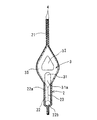
図1は、本発明に係る液体バッグの実施の形態1を示す縦断面図、図2は同実施の形態1における口部材の縦断面図、図3は同実施の形態1における口部材の各口部を開口させた状態の斜視図、図4は図1のA−A断面図、図5は図1のB−B断面図、図6は図1のC−C断面図、図7は液体バッグの湿潤器としての使用形態を示す縦断面図、図8は液体バッグのネブライザーとしての使用形態を示す縦断面図である。
【0020】
この液体バッグ1は、略封筒状のバッグ本体2と、このバッグ本体2に予め収容された水(滅菌精製水)Wと、バッグ本体2の周縁部の一部に封着された口部材3とから主としてなる。
【0021】
バッグ本体2は、柔軟な熱可塑性樹脂製(例えば厚み約0.25mmのポリエチレン樹脂製)シート4、4で、略封筒状に構成されている。なお、21はヒートプレスにより2枚のシート4、4が熱溶着されシールされたバッグ本体2の周縁溶着部である。
【0022】
口部材3は、射出一体成形により形成されたものであって、バッグ本体2の周縁部の一部に封着された筒状の封着部33と、この封着部33が延出する管状部34とを有している。
【0023】
封着部33は、略菱形柱状に形成されており、その封着面である外側面には、バッグ本体2の周縁部、つまり封着部33が封着されたバッグ本体2の上辺と略平行に複数本の溝部33aが形成されている。この複数本の溝部33aを封着部33に設けることにより、バッグ本体2の対面するシート4,4の周縁部にて口部材3の封着部33を挟み込むようにして熱溶着する際の溶着時間を短縮することができる。なお、封着部33の後述の側方開口部31aの周囲はシート4、4と熱溶着されている。
【0024】
管状部34は、湿潤器として使用可能またはネブライザーとして使用可能な接続構造に形成されており、バッグ本体2に導入する気体供給源(例えば酸素ボンベ)の流出口またはバッグ本体2内の液体を噴霧するための噴霧ノズルと選択的に接続可能な第1管部35と、液体成分を付加した気体の受容器または前記噴霧ノズルのドレンと選択的に接続可能な第2管部36とを備え、これらの各接続部35、36から第1口路31および第2口路32を介してバッグ本体2内にそれぞれ通じる。
【0025】
第1管部35は、上方へ開口するカップ形状に形成されており、その外周面にはネジ部35aが形成されるとともに、開口はフィルム39が熱溶着して閉鎖されている。
第2管部36は、バッグ本体2内に導入されて液体成分が付加される気体を図示省略の受容器に送るための弾性チューブと接続される斜め上方に向かって形成されたチューブ接続口37と、第1管部35の開口に接続された噴霧ノズル61(図8参照)から噴霧される液体Wの一部をドレン52からバッグ本体2内に還流させるためのドレンパイプ63と接続される水平突出状に形成されたパイプ接続口38とからなる。パイプ接続口38はフィルム40が熱溶着して閉鎖されている。一方、チューブ接続口37の先端は有底筒形の封鎖部41が一体形成されて閉鎖されている。なお、この封鎖部41を含めた口部材3の製造方法について詳しくは後述する。
第1管部35の開口と連通する第1口路31は、封着部33の内部でL字状に屈曲して封着部33の略菱形頂部で、かつ封着面で囲まれてバッグ本体2の周縁方向(上辺に沿った方向)に開口する側方開口部31aを有している。
第2管部36は、封着部33の底面でバッグ本体2内に開口する下方開口部32aを有しており、この下方開口部32aから上方へ向かって管状部で略直角に屈曲してパイプ接続口38と連通し、かつこの屈曲部分から上方に分岐して所定上方位置で斜め上方に屈曲してチューブ接続口37と連通している。
【0026】
このように構成された口部材3は、全体が射出成形によって一体成形されている。この射出成形の金型内には、第1口路31を屈曲形成するために第1管部35の開口側と側方開口部31a側の対応位置にそれぞれ芯となる型がセットされ、第2口路32を屈曲形成するためにチューブ接続口37側とパイプ接続口38側と下方開口部32a側の対応位置にそれぞれ芯となる型がセットされる。この金型内に溶融樹脂を注入し、樹脂が固化することにより口部材3が成形される。この射出成形直後の口部材3は、チューブ接続口37の先端に連設された封鎖部41(図2参照)の先端は開口した状態となっており、射出成形後に先端口が閉鎖されている。さらに詳しく説明すると、この封鎖部41は、その筒状胴部41dの外周面に一対2枚の突片41a、41aが180°の対向位置に形成されるとともに、チューブ接続口37の先端部との接続部分には薄肉筒状の脆弱部41bが形成されている。また、封鎖部41の先端には、チューブ接続口37を塞ぐ蓋部41cが設けられている。この封鎖部41は、口部材3の射出成形において、チューブ接続口37の先端部に連設される脆弱部41bと、脆弱部41bの先端に連設される胴部41dと、胴部41dの一対の突片41a、41aと、胴部41dの先端口近傍に設けられた図示省略の余剰部とを一体に成形し、射出成形後に、前記余剰部を熱によって(例えば熱板や半田ごて等に押し付けて)溶融し、その溶融した余剰部(溶融樹脂)にて胴部41dの先端口を密封することにより蓋部41cを形成している。つまり、この封鎖部41によって、チューブ接続口37の先端開口部(図3参照)がねじ切り開封可能に閉鎖されている。なお、封鎖部41は、一対の突片41a、41aを省略したものでもよく、この場合、胴部41dを倒す方向に押して脆弱部41bを折ることにより開封することができる。
【0027】
この液体バッグ1は、使用前の状態では、上述したように(図1、図2参照)口部材3が、第1管部35の開口(接続口)にフィルム39が熱溶着されて閉鎖され、チューブ接続口37が封鎖部41にて閉鎖され、パイプ接続口38にフィルム40が熱溶着されて閉鎖されることによって、運搬や保管や取扱いの際に水Wが口部材3から外部にこぼれず、かつバッグ本体2内の水Wが外気から遮断されて雑菌等が混入せず衛生状態が保持されている。
【0028】
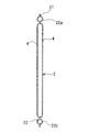
さて、バッグ本体2は、対面するシート4、4のヒートプレスによる熱溶着により区画形成された略コ字状の第1空間部としての誘導路22をさらに備えている。すなわち、バッグ本体2の上辺と、一方側辺(この場合右側辺)と、底辺とに各々所定間隔をもって沿って略コ字形の区画溶着部23が形成され、この区画溶着部23と周縁溶着部21とで、第2空間部としての液収納部24と区画された誘導路22が形成されている。
【0029】
この誘導路22は、口部材3の第1口路31の側方開口部31aからバッグ本体2の上辺に沿って略横方向に延びる上水平路22aと、次いで屈曲してバッグ本体2の一方の側辺(この場合右側辺)に沿って下方へ延びる下降路22bと、この下降路22bから底辺に沿って水平に延びる下水平路22cとからなり、この下水平路22cに対向する区画溶着部23には、誘導路22と液収納部24とを連通する連通路としての多数の微細路25、25…が1列で、等ピッチ(中心間距離:約4.0mm)に形成されている。この誘導路22は、その区画形成後に熱湯を入れるか、未加熱の水を入れた後その水およびシートを加熱してトンネル状に膨らませた上で(トンネル状空間が作製される部分以外の部分に外部から圧力をかけて)冷却し硬化させることにより、それぞれ自己保持可能なトンネル状空間(幅:8mm、全高さ:6mm)を有するように構成されている。なお、多数の微細路は、それらの微細路に対応して多数の溝を列設し対向する同一構成の一対の金型により対面するシートを挟み込み、ヒートシールすることによって形成され、そして微細路形成後に底辺のヒートプレスが行われている。
【0030】
(使用形態1)
次に、以上の構成を備えた液体バッグ1を湿潤器として使用する場合の手順の一例を説明する。
先ず、図1と図2で説明した口部材3のチューブ接続口37の封鎖部41を、その一対の突片41a、41aに指を掛けて回し、くびれ部41bをねじ切って除去し、チューブ接続口37を開ける(図3参照)。そして、図7に示すように、酸素の供給先である図示省略の酸素マスクに一端が接続された弾性チューブ51の他端にチューブ接続口37を差し込んで接続する。一方、口部材3の第1管部35のネジ部35aに接続部52を螺着する。このとき、接続部52中心の酸素導入口52aの下方突出部がフィルム39(図2参照)を突き破って第1口路31と連通する。次いで、図示省略の酸素ボンベから酸素を供給するパイプの端部を接続部主部53を介して接続部52に接続する。なお、パイプ接続口38はフィルム40(図2参照)にて閉鎖されたままにしておく。
【0031】
液体バッグ1を用いて構成した湿潤器50の作動は、先ず、図示省略する酸素ボンベから酸素を口部材3の第1口路31に導入し、バッグ本体2の誘導路22の上水平路22a、下降路22bおよび下水平路22cと、微細路25、25…を介して液収納部24に導入する。この際、酸素は、多数の微細路25、25…によって、小さく分割されるとともに、液収納部24の底部から水中全体に広がってバブリングできる。これによって、液収納部24内の水面上に得られる酸素には、効率良く十分に水分(水蒸気および霧状の水)が付加され、加湿酸素として口部材3の第2口路32および弾性チューブ51を介して酸素マスクへ送り出される。この際、誘導路22が自己保持可能なトンネル状空間で構成されているので、酸素のバッグ本体2内への導入がスムースである。この湿潤器50は、誘導路22の酸素出口(多数の微細路25、25…)がバッグ本体2の底部に沿って配置されているため、水Wがバッグ本体2の底部付近まで減少しても確実にバブリングでき、この水Wを無駄なく使用することができる。また、水Wがある程度まで減少した使用後の状態では、バッグ本体2を小さくたためるので廃棄に便利である。
【0032】
(使用形態2)
次に、液体バッグ1をネブライザー(噴霧器)として使用する場合の手順の一例を説明する。
先ず、図8に示すように、(図1の状態の)液体バッグ1の口部材3の第1管部35のネジ部35aに噴霧ノズル61を螺着する。このとき、噴霧ノズル61の液導入口61aの下方突出部がフィルム39(図2参照)を突き破って第1口路31と連通する。この噴霧ノズル61は、前記液導入口61aの上端に設けられた吸上部61bと、吸上部61bの上方に設けられた酸素を噴射するノズル部61cと、霧状の水を含んだ酸素と共に外部へ空気を誘導する誘導部61dと、水滴を排水するドレン61eとを備えている。また、噴霧ノズル61のノズル部61cは、図示省略の酸素ボンベから酸素を供給するパイプの端部と接続具62を介して接続される。一方、噴霧ノズル61のドレン61cに一端を接続したドレンパイプ63の他端を、口部材3のパイプ接続口38に接続する。このとき、ドレンパイプ63の他端に取り付けられた差込具にてフィルム40(図2参照)を突き破り、ドレンパイプ63と第2口路32とを連通させる。
【0033】
液体バッグ1を用いて構成したネブライザー(噴霧器)60の作動は、先ず、図示省略する酸素ボンベから酸素を噴霧ノズル61のノズル部61cに供給して内部に噴射させる。このノズル部61cからの酸素の噴射によって、噴霧ノズル61内に陰圧が生じてバッグ本体2から口部材3を介して吸上部61bに水Wが吸上げられ、吸上部61b上端の小孔から霧状の水が噴出して酸素に付加され、誘導部61d内で霧状の水を含む酸素の流れに誘引されて外部から空気が導入され、霧状の水を含んだ酸素と共に再び空気が外部に噴出する。ここで、バッグ本体2の誘導路22からの水Wの吸引に際しては、誘導路22が自己保持可能なトンネル状空間で構成されているので、水の吸引が抵抗なく行われ、霧状の水の酸素への付加がスムースである。また、噴霧ノズル61の内面に付着した水滴は、ドレン61cからドレンパイプ63、口部材3の第2口路32を通ってバッグ本体2内の液収納部24に還流する。このネブライザー60は、誘導路22の水取入れ口(多数の微細路25、25…)がバッグ本体2の底部に沿って配置されているため、水Wがバッグ本体2の底部付近まで減少するまで誘導路22にて確実に吸引され、この水Wを無駄なく使用することができる。また、水Wがある程度まで減少した使用後の状態では、バッグ本体2を小さくたためるので廃棄に便利である。
【0034】
[他の実施の形態]
上記実施の形態では、バッグ本体を略封筒状(長方形)に形成して、誘導路をコの字状に形成したが、誘導路の形状や、微細路を形成する位置は、使用目的に合う程度にできれば特に限定されず、例えば、上水平路のみで誘導路を形成し、その一部に微細路を形成してもよく、あるいは上水平路と下降路とから倒立L字状に誘導路を形成し、少なくとも下降路の一部に微細路を形成してもよい。また、バッグ本体の形状は、長方形以外にも、正方形や円形や長円形や楕円形等であってもよい。
【0035】
【発明の効果】
本発明の液体バッグは、口部材が、二つの口路を備え、一方の第1口路が、封着部の内部で略L字状に屈曲してバッグ本体の周縁方向に開口し、他方の第2口路が封着部の底面でバッグ本体内に開口するので、バッグ本体と口部材との封着に際して、バッグ本体の対面するシートの一部を併せて熱溶着してバッグ本体内を第1口路側と第2口路側に区画することが可能となる。つまり、本発明は、誘導路を必要とする場合、その誘導路を、口部材近傍でバッグ本体内の一部を熱溶着する際、口部材の厚みがあるために縦方向に形成することは難しく、通常、別途パイプ材を必要とするところを、封着領域内における側方開口部の上下位置に溶着部をバッグ本体の周縁部に沿って形成することによって誘導路を形成できる。また、口部材からバッグ本体の周縁部に沿って溶着部を底部にまで延ばすことができ、誘導路をバッグ本体の底部まで省スペースで廻り込ませて容易に形成することが可能となる。
【図面の簡単な説明】
【図1】本発明に係る液体バッグの実施の形態1を示す縦断面図である。
【図2】同実施の形態1における口部材の縦断面図である。
【図3】同実施の形態1における口部材の各口部を開口させた状態の斜視図である。
【図4】図1のA−A断面図である。
【図5】図1のB−B断面図である。
【図6】図1のC−C断面図である。
【図7】液体バッグの湿潤器としての使用形態を示す縦断面図である。
【図8】液体バッグのネブライザーとしての使用形態を示す縦断面図である。
【符号の説明】
2 バッグ本体
3 口部材
4 シート
23 区画溶着部
25 微細路
31 第1口路
32 第2口路
33 封着部
34 管状部
35 第1管部
36 第2管部
37 チューブ接続口
38 パイプ接続口
39、40 フィルム
51 弾性チューブ
W 液体[0001]
BACKGROUND OF THE INVENTION
The present invention relates to a liquid bag, a liquid bag mouth member, and a method for manufacturing the same, and in particular, a gas moisture adder that adds moisture (water vapor or mist water) to a gas such as air, oxygen, nitrogen, carbon dioxide, and the like. Specifically, the present invention relates to a liquid bag that can be used as an oxygen wetting device or a nebulizer.
[0002]
[Prior art and problems to be solved by the invention]
The following (1), (2), and (3) are known as conventional liquid bags having a bag body made of a flexible thermoplastic resin sheet.
(1) A liquid bag in which one mouth member having one mouth is sealed to a part of the peripheral edge of an envelope-shaped bag body.
(2) A liquid bag in which one mouth member having two mouth parts is sealed to a part of the peripheral edge of an envelope-shaped bag body (for example, Japanese Patent Laid-Open No. 2000-190997).
(3) One mouth member having one mouth is sealed to a part of the peripheral edge of the envelope-shaped bag body, and a part of the sheet facing the bag body is thermally welded by a special heat sealing method. A multi-chamber liquid bag with the interior divided into two rooms. This liquid bag is configured such that when one of the rooms is pressed, the welded portions partitioned into two rooms communicate with each other so that the liquid agent stored in each room is mixed (for example, JP-A-2-46771) ).
[0003]
By the way, as a simple oxygen inhaler (humidifier) that can supply oxygen (water vapor or mist-like water) by adding oxygen, an oxygen introduction pipe attached to a cylindrical hard bottle is known. Since sterile water is used at the time of use, it takes time and there is a problem in terms of hygiene. Moreover, although the disposable box-shaped hard bottle was also used as a hard bottle, since it was bulky, the manufacturing apparatus became so large, the manufacturing cost was high, and it was inconvenient for disposal. For this reason, it is conceivable to add a bubbling function to a liquid bag composed of a flexible container. However, if the bubbling function is added to the liquid bag of (1), (2), (3), the gas is supplied to the bag body. Since other members such as a tube for introducing into the bag are required, and in (1) and (3), there is only one port port, the port for discharging the gas introduced into the bag body to the outside One more port is required, which increases the number of parts, complicates the manufacturing process, and increases costs.
[0004]
Accordingly, one of the main objects of the present invention is to provide a liquid bag, a liquid bag mouth member, and a method of manufacturing the same that allow bubbling with a simple configuration without increasing the number of parts.
[0005]
[Means for Solving the Problems]
The present invention comprises a bag body configured to be made of a flexible thermoplastic resin sheet and containing a liquid, and a thermoplastic resin mouth member sealed to a part of the peripheral edge of the bag body,
The bag body has a section welding portion that forms a guide path by welding along the peripheral edge of the bag body.
The mouth member has a first mouth passage and a second mouth passage, has a cylindrical sealing portion sealed to the back body, and the first mouth passage isOn the side of the cylindrical sealIn the peripheral direction of the bag bodyOpen and communicate with the taxiwayThe liquid bag is characterized in that the second opening is opened in the bag body at the bottom surface of the cylindrical sealing portion.
[0006]
That is, according to the present invention, the mouth member includes two mouth passages, and one first mouth passage is bent in a substantially L shape inside the sealing portion and opens in the peripheral direction of the bag body, Since the second opening opens into the bag body at the bottom of the sealing portion, when sealing the bag body and the mouth member, a part of the sheet facing the bag body is also heat-welded and the inside of the bag body is It becomes possible to divide into the 1st mouth side and the 2nd mouth side.
[0007]
Specifically, the sheet facing the bag body is thermally welded to form a partition weld portion, and the first space portion communicating with the first mouth passage and the second space communicating with the second mouth passage within the bag body. It can be divided into parts. In this case, the gas introduced into the bag body from the first port or the second port is formed by forming a communication path that allows the first space and the second space to communicate with a part of the compartment weld. It can send to the 2nd mouth way or the 1st mouth way via a communicating path. Further, by forming the communication path from a large number of fine passages, gas is introduced from the first mouth passage to the first space portion or from the second mouth passage to the second space portion, and in the liquid in the second space portion or Bubbling can be performed in the liquid in the first space. Preferably, the first space is formed as a gas and / or liquid guiding path along the peripheral edge of the bag body, and a number of micro paths are formed in the lower portion of the guiding path. In other words, when the present invention requires a guide path, the guide path is formed in the vertical direction due to the thickness of the mouth member when part of the bag body is thermally welded in the vicinity of the mouth member. It is difficult, and a guide path can be formed by forming a partition welding portion along the peripheral edge portion of the bag body at a position above and below the side opening in the sealing region, which is usually difficult and requires a pipe material. Further, the section welded portion can be extended from the mouth member to the bottom portion along the peripheral edge portion of the bag main body, and the guide path can be easily formed by wrapping around the bottom portion of the bag main body in a space-saving manner. In this case, if a fine path is formed in a portion along the bottom of the bag body in the guide path, a large number of fine paths as gas outlets of the guide path for guiding gas into the bag body, or liquid in the bag body A large number of fine passages are formed along the bottom of the bag body as liquid intakes of the guide passage that guides to the bag. Therefore, when the liquid bag is used as, for example, a humidifier, the introduced gas can be bubbled from the bottom of the liquid bag, thereby obtaining high contact efficiency between the gas and the liquid, and a small amount of liquid in the bag body. Even if it remains, it can be surely bubbled, and water (sterile water) can be used without waste. Further, when the liquid bag is used as, for example, a nebulizer, it is preferable that water can be sucked to the outside through the guide path until the water in the bag body is almost lost, and water (sterile water) can be used without waste.
[0008]
In the present invention, if the guiding path of the bag body is configured in advance as a tunnel-like space formed so as to be capable of self-holding, the introduction of gas can be performed smoothly with reduced resistance, or liquid can be drawn from within the bag body. Since it can suck | suck smoothly without blocking, it is preferable. The tunnel-shaped space is not particularly limited, but can be configured to be able to self-hold in a tunnel shape by heat-treating at least one of the facing sheet portions. More specifically, in the tunnel-like space, the facing sheet portion is softened by heating at least one portion thereof and held in a tunnel shape, and then cured by cooling (including natural cooling) to self-activate. It can be formed so that it can be held. Specifically, a heated fluid (water, air, etc.) is put between facing sheet parts (for example, a polyethylene resin or polypropylene resin sheet having a thickness of 80 to 300 μm), or an unheated fluid is put into the outside. Or by combining these methods as appropriate, and pressing from a portion other than the tunnel-shaped space to be produced (that is, the bag portion), inflating and holding the corresponding portion in a tunnel shape, and then cooling It may be formed by curing, or may be formed by heating the facing sheet part and inflating and holding it by decompression from the outside, and then cooling the corresponding part in the same manner. In addition, the formation of a large number of micro paths is performed by forming non-welded portions as a large number of micro paths by intermittently performing thermal welding of sheets facing the bag body. Specifically, a large number of fine paths can be formed easily and at once by heat-pressing the sheet facing through the comb-shaped pins and extracting the pins. Alternatively, it can be formed by arranging a large number of grooves corresponding to these fine paths and sandwiching the facing sheets with a pair of opposing molds facing each other and heat-sealing. This fine path has an average pitch (0.1 to 100.0 mm, preferably 2.0 to 10 mm) as appropriate, for example, with a non-welded portion having an average width of 0.5 to 10.0 mm, preferably 0.5 to 3.0 mm. Heat welding so that it can be formed at 8.0 mm).
[0009]
In the present invention, the sealing part of the mouth member is preferably formed in a substantially rhomboid columnar shape. When configured in this way, when forming the guide path, guidance with the side opening of the sealing part is performed. Thermal welding of the bag body (facing sheet) at the connection portion of the road can be performed more easily and reliably. In other words, if both of the two mouth passages of the mouth member have a straight shape having an opening on the bottom surface of the sealing portion, it is necessary to partition the bag body by forming a longitudinal weld portion between the two mouth passages. However, depending on the thickness of the mouth member (as described above), it is difficult or impossible to heat weld in the vertical direction, or the mouth member is formed in a shape in which two rhombus columns are connected and integrated, and the thin wall portion is connected. It is also conceivable to thermally weld a part of the bag body in the vertical direction, but if this is done, the shape and size of the mouth member will be increased, and manufacturing difficulties and manufacturing costs will increase. In contrast, in the present invention, since the first opening is a bent opening and the side opening thereof is open to the top of the approximately rhomboid column, the top side of the approximately rhombus column can be provided. The sheet facing the bag body can be thermally welded at the upper and lower positions of the side opening to easily and reliably form the guide path in the peripheral direction of the bag body, and this guide path is few along the peripheral part of the bag body. It can be easily formed with a simple configuration without using pipe material (such as an oxygen introduction pipe) in the space.
[0010]
In the present invention, the mouth member further includes a tubular portion from which the sealing portion extends, and the tubular portion communicates with the first mouth passage, and the second tube communicates with the second mouth passage. It is good also to have a part. In this case, the second pipe portion of the tubular portion of the mouth member has a tube connection port that can be connected to the elastic tube, and a pipe connection port that can be connected to a pipe through which liquid and / or gas flows. Also good. With this configuration, for example, when the liquid bag is used as a wetting device (oxygen inhaler), the other end of the pipe whose one end is connected to the outlet of the oxygen cylinder is connected to the first pipe portion via the connector. It can be used by connecting the other end of the elastic tube connected to the opening and having one end connected to the oxygen mask to the tube connection port. Further, when the liquid bag is used as a nebulizer (a sprayer), a spray nozzle to which oxygen is supplied from an oxygen cylinder is connected to the opening of the first pipe portion, and a drain having one end connected to a drain provided in the spray nozzle. The other end of the pipe can be connected to a pipe connection port.
[0011]
Furthermore, the tube connection port is sealed so that the tip of the tube connection port can be threaded and opened, and the opening of the first tube unit and the pipe connection port of the second tube unit are each closed by heat-sealing a film. It may be. In this way, the liquid in the liquid bag will not spill outside from each mouth part during transportation, storage and handling, and the liquid in the liquid bag will be blocked from the outside air, so that the sanitary state is maintained. Can do. In use, each film of the connection port of the first port and the drain pipe connection port of the second port can be pierced and communicated at the flow channel port of the connection member connected to each connection port. The tip of the two-way tube connection port can be opened by screwing, so connect each necessary connection member directly without touching each connection port by hand, and set a humidifier or nebulizer hygienically Can do. This will be described in detail in an embodiment described later. In addition, each opening of a tubular part is not limited to such a closing method, For example, the method etc. which close with a rubber stopper etc. are also employable.
[0012]
In the present invention, the flexible thermoplastic resin sheet constituting the bag body is not particularly limited as long as it can be used as a liquid storage bag (bag), but polyethylene resin, polypropylene resin, polyethylene terephthalate resin, ethylene vinyl. Resin such as alcohol copolymer (EVOH resin), and multilayer resin such as polyethylene / nylon multilayer resin, polyethylene / aluminum foil multilayer resin, and the thickness: 0.1-1.00 mm. Among these, it is preferable to use a gas-impermeable material such as an ethylene vinyl alcohol copolymer or a polyethylene / aluminum foil multilayer resin because the contents of the chemical solution can be prevented from being oxidized. Moreover, since the liquid bag according to the present invention is made of a flexible thermoplastic resin sheet, the liquid bag is entirely flexible and has a bubbling sound silencing effect.
The mouth member is not particularly limited as long as it is a hard thermoplastic resin, and examples thereof include polyethylene resin, polypropylene resin, polyethylene terephthalate resin, and ethylene vinyl alcohol copolymer (EVOH resin).
[0013]
Examples of the gas that can be bubbled into the liquid stored in the bag in advance using the liquid bag according to the present invention include air, oxygen, nitrogen, carbon dioxide, and a mixed gas thereof. As the liquid stored in advance, water is representative and other oils can be exemplified. The water includes chemicals and other liquids (for example, alcohol) (aqueous solutions).
[0014]
As a specific example of such a liquid bag, in addition to the above-described medical or emergency oxygen inhaler (wetting device that contains oxygen in an appropriate amount of water) and a nebulizer (atomizer), humidity adjustment or air conditioning Gaseous liquid component adders, goldfish simple bags (oxygen bubbling), chemical antioxidant bags (nitrogen bubbling), soapy agitation bags (bubbled with air bubbling), etc. it can. In addition, the chemical antioxidant bag can be stored for a long period of time by bubbling nitrogen and without discharging the liquid, and sealing the bag. In addition, as a use example in the case where there is no communication path in the compartment welded portion that partitions the bag body into the first space portion and the second space portion, the first space portion and the second space portion have a predetermined volume ratio. The inside of the bag body is partitioned by the partition welding portion, and when used, the liquid in the first space portion and the different liquid in the second space portion are discharged to the outside through the first and
[0015]
The liquid bag which concerns on this invention can set freely the quantity and ratio of the liquid and gas which are filled according to a use purpose. In particular, the liquid bag of the present invention can remove the gas in the vacant space without being filled with the contents and can be sealed as compared with a bulky and hard liquid bottle, and does not mind the contamination of the gas part. Well, when an unstable substance is put in a gas (oxygen or the like), there is an advantage that replacement with an inert gas (nitrogen or the like) is unnecessary. Compared to bulky and hard liquid bottles, it can be packed and stacked in various directions when packed in boxes or on shelves, so there is less wasted space and space can be used effectively. .
[0016]
Furthermore, if the liquid bag according to the present invention has the same shape and method of use, the amount used per unit time is the same, so the time can be adjusted by changing the amount of liquid (for example, for 30 minutes, 1 hour For 2 hours). Also, several liquid bags can be connected to adjust the time (30 minutes + 1 hour = 1 hour 30 minutes).
[0017]
According to another aspect, the present invention includes a cylindrical sealing portion having a first opening and a second opening that are sealed to a part of a peripheral portion of a bag main body that stores a liquid. It is possible to provide a liquid bag mouth member characterized in that the path is opened at the side surface of the sealing portion, and the second mouth path is opened at the bottom surface of the sealing portion. Due to the opening of the first mouth path, the guide path (described above) can be formed together from the first mouth path when the bag body and the mouth member are sealed.
[0018]
According to another aspect of the present invention, there is provided a cylindrical sealing portion that is sealed to a part of a peripheral portion of a bag body that stores a liquid and has a first opening and a second opening, and the cylindrical sealing. A tubular portion that extends from the second opening of the landing portion, bends inside, and further has a distal end opening, a thin-walled fragile portion that is continuous with the distal end opening, and a continuous portion at the distal end of the fragile portion A cylindrical torso,
The liquid bag is characterized in that the front end opening of the cylindrical body is sealed, the first opening is opened at the side of the cylindrical sealing part, and the second opening is opened at the bottom of the cylindrical sealing part. A mouthpiece can be provided.
According to still another aspect of the present invention, there is provided a manufacturing method for manufacturing, by injection molding, a liquid bag mouth member that is sealed to a part of a peripheral portion of a bag body that stores liquid,
The mouth member isThe first and second outlets are provided,A cylindrical sealing part sealed to a part of the peripheral edge of the bag body, and this cylindrical sealing partSecond exitExtend from and bend insideAnd thenA tubular portion having a tip opening, a thin tubular weakened portion continuous to the tip opening, and a cylindrical body continuous to the tip of the weakened portion, andThe first opening opens at the side of the cylindrical sealing part, the second opening opens at the bottom of the cylindrical sealing part,
In injection molding, in addition to the fragile part and the cylindrical body part, an excess part is integrally formed in the vicinity of the front end of the cylindrical body part,
After injection molding, the surplus part is melted by heat, and the tip end of the cylindrical body is sealed at the melted surplus part.Tubular partIt is possible to provide a manufacturing method of a liquid bag mouth member characterized in that the front end opening of the liquid bag is removed from the fragile portion by an applied force and closed so as to be opened.
That is, the liquid bag mouth memberCylindrical sealing partAnd a tubular part, bent at this tubular partAndWhen manufacturing the mouth member for a liquid bag in which the distal end opening on the tubular portion side is closed so that it can be opened by an applied force, in the mold of the injection molding device,Cylindrical sealing partA thin-walled cylindrical shape connected to the distal end opening on the tubular portion side by setting a mold that becomes a core from the opening on the side and the opening on the tubular portion side, and injecting molten resin into the mold and solidifying it The fragile portion, the cylindrical barrel portion connected to the tip of the fragile portion, and the surplus portion provided in the vicinity of the front end of the barrel portion can be easily integrally formed, and then the surplus portion is heated. Melted with a plate or soldering iron, etc.Cylindrical bodyIt is possible to easily seal the tip end of the. Therefore, a “separate member that can be opened by an applied force” that closes the distal end opening on the tubular portion side is manufactured separately, and the separate member is later welded to the distal end opening on the tubular portion side of the mouth member and closed. Compared with the method, since the present invention is integrally molded, the liquid bag mouth member can be manufactured with high quality and efficiency at low cost.
[0019]
DETAILED DESCRIPTION OF THE INVENTION
Hereinafter, the present invention will be described in detail based on the embodiments shown in the drawings. Note that the present invention is not limited thereby.
[Embodiment 1]
1 is a longitudinal sectional view showing Embodiment 1 of a liquid bag according to the present invention, FIG. 2 is a longitudinal sectional view of a mouth member in Embodiment 1, and FIG. 3 is each of the mouth members in Embodiment 1. As shown in FIG. 4 is a cross-sectional view taken along the line AA in FIG. 1, FIG. 5 is a cross-sectional view taken along the line BB in FIG. 1, FIG. 6 is a cross-sectional view taken along the line CC in FIG. FIG. 8 is a vertical cross-sectional view showing a usage pattern of a liquid bag as a wetting device, and FIG. 8 is a vertical cross-sectional view showing a usage pattern of the liquid bag as a nebulizer.
[0020]
The liquid bag 1 includes a substantially envelope-shaped
[0021]
The
[0022]
The
[0023]
The sealing
[0024]
The
[0025]
The
The
The
The
[0026]
The
[0027]
In the state before use, the liquid bag 1 is closed as described above (see FIGS. 1 and 2), with the
[0028]
The
[0029]
The
[0030]
(Usage form 1)
Next, an example of a procedure when the liquid bag 1 having the above configuration is used as a wetting device will be described.
First, the sealing
[0031]
The operation of the wetting
[0032]
(Usage form 2)
Next, an example of a procedure when the liquid bag 1 is used as a nebulizer (a sprayer) will be described.
First, as shown in FIG. 8, the
[0033]
In the operation of the nebulizer (sprayer) 60 configured by using the liquid bag 1, first, oxygen is supplied from a not-shown oxygen cylinder to the
[0034]
[Other embodiments]
In the above embodiment, the bag body is formed in a substantially envelope shape (rectangular shape) and the guide path is formed in a U-shape. However, the shape of the guide path and the position where the fine path is formed suit the purpose of use. There is no particular limitation as long as it can be reduced, and for example, the guide path may be formed only by the upper horizontal path, and a fine path may be formed in a part thereof, or the guide path in an inverted L shape from the upper horizontal path and the descending path And a fine path may be formed at least in part of the descending path. The shape of the bag body may be a square, a circle, an oval, an ellipse, or the like other than a rectangle.
[0035]
【The invention's effect】
In the liquid bag of the present invention, the mouth member includes two mouth passages, and one first mouth passage is bent in a substantially L shape inside the sealing portion and opens in the peripheral direction of the bag body, and the other Since the second opening of the bag opens into the bag body at the bottom surface of the sealing portion, when sealing the bag body and the mouth member, a part of the sheet facing the bag body is also heat-welded and the bag body is Can be divided into a first mouth side and a second mouth side. In other words, when the present invention requires a guide path, the guide path is formed in the vertical direction due to the thickness of the mouth member when part of the bag body is thermally welded in the vicinity of the mouth member. It is difficult, and a guide path can be formed by forming a welded portion along the peripheral edge of the bag body at a position above and below the side opening in the sealing region, which is usually difficult and requires a pipe material. Further, the welded portion can be extended from the mouth member to the bottom portion along the peripheral edge portion of the bag main body, and the guide path can be easily formed by wrapping around the bottom portion of the bag main body in a space-saving manner.
[Brief description of the drawings]
FIG. 1 is a longitudinal sectional view showing Embodiment 1 of a liquid bag according to the present invention.
FIG. 2 is a longitudinal sectional view of a mouth member in the first embodiment.
FIG. 3 is a perspective view showing a state in which each mouth portion of the mouth member in the first embodiment is opened.
4 is a cross-sectional view taken along the line AA in FIG.
5 is a cross-sectional view taken along the line BB in FIG.
6 is a cross-sectional view taken along the line CC in FIG. 1. FIG.
FIG. 7 is a longitudinal sectional view showing a usage pattern of a liquid bag as a wetting device.
FIG. 8 is a longitudinal sectional view showing a usage pattern of a liquid bag as a nebulizer.
[Explanation of symbols]
2 Bag body
3 mouth material
4 sheets
23 Weld zone
25 Fine path
31 1st exit
32 Second Exit
33 Sealing part
34 Tubular part
35 1st pipe
36 Second Pipe
37 Tube connection
38 Pipe connection
39, 40 films
51 Elastic tube
W liquid
Claims (8)
バッグ本体が、その周縁部に沿ってバッグ本体内に誘導する誘導路を溶着により区画形成する区画溶着部を有し、
口部材が、第1口路および第2口路を備え、バック本体に封着される筒状封着部を有し、かつ、第1口路が筒状封着部の側面でバッグ本体の周縁方向に開口して前記誘導路に連通し、第2口路が筒状封着部の底面でバッグ本体内に開口したことを特徴とする液体バッグ。A bag body configured to contain a liquid made of a flexible thermoplastic resin, and a thermoplastic resin mouth member sealed to a part of the peripheral edge of the bag body,
The bag body has a section welding portion that forms a guide path by welding along the peripheral edge of the bag body.
The mouth member has a first mouth passage and a second mouth passage, has a cylindrical sealing portion sealed to the back body, and the first mouth passage is formed on the side surface of the cylindrical sealing portion of the bag body. A liquid bag characterized in that it opens in the peripheral direction and communicates with the guide path, and the second opening opens into the bag body at the bottom of the cylindrical sealing portion.
Priority Applications (8)
| Application Number | Priority Date | Filing Date | Title |
|---|---|---|---|
| JP2002216825A JP4261834B2 (en) | 2002-07-25 | 2002-07-25 | Liquid bag, liquid bag mouth member and method of manufacturing the same |
| PCT/JP2003/009303 WO2004011073A1 (en) | 2002-07-25 | 2003-07-23 | Liquid bag, liquid bag mouth member, and method of producing the same |
| US10/521,460 US7198255B2 (en) | 2002-07-25 | 2003-07-23 | Liquid bag, liquid bag mouth member, and method of producing the same |
| CNB038174448A CN100536953C (en) | 2002-07-25 | 2003-07-23 | Liquid bag, liquid bag mouth member, and method of producing the same |
| AU2003252234A AU2003252234A1 (en) | 2002-07-25 | 2003-07-23 | Liquid bag, liquid bag mouth member, and method of producing the same |
| EP03771281A EP1535643A4 (en) | 2002-07-25 | 2003-07-23 | Liquid bag, liquid bag mouth member, and method of producing the same |
| DE03771281T DE03771281T1 (en) | 2002-07-25 | 2003-07-23 | LIQUID BAG, LIQUID BAG MOUTH AND MANUFACTURING METHOD THEREFOR |
| KR1020057000607A KR100687177B1 (en) | 2002-07-25 | 2003-07-23 | Liquid bag and liquid bag mouth member |
Applications Claiming Priority (1)
| Application Number | Priority Date | Filing Date | Title |
|---|---|---|---|
| JP2002216825A JP4261834B2 (en) | 2002-07-25 | 2002-07-25 | Liquid bag, liquid bag mouth member and method of manufacturing the same |
Publications (3)
| Publication Number | Publication Date |
|---|---|
| JP2004057296A JP2004057296A (en) | 2004-02-26 |
| JP2004057296A5 JP2004057296A5 (en) | 2005-10-27 |
| JP4261834B2 true JP4261834B2 (en) | 2009-04-30 |
Family
ID=31184588
Family Applications (1)
| Application Number | Title | Priority Date | Filing Date |
|---|---|---|---|
| JP2002216825A Expired - Fee Related JP4261834B2 (en) | 2002-07-25 | 2002-07-25 | Liquid bag, liquid bag mouth member and method of manufacturing the same |
Country Status (8)
| Country | Link |
|---|---|
| US (1) | US7198255B2 (en) |
| EP (1) | EP1535643A4 (en) |
| JP (1) | JP4261834B2 (en) |
| KR (1) | KR100687177B1 (en) |
| CN (1) | CN100536953C (en) |
| AU (1) | AU2003252234A1 (en) |
| DE (1) | DE03771281T1 (en) |
| WO (1) | WO2004011073A1 (en) |
Cited By (1)
| Publication number | Priority date | Publication date | Assignee | Title |
|---|---|---|---|---|
| TWI730203B (en) | 2016-12-01 | 2021-06-11 | 德商科茲股份有限公司 | Crack gap mould for producing a particle foam part together with an apparatus for producing a particle foam part |
Families Citing this family (29)
| Publication number | Priority date | Publication date | Assignee | Title |
|---|---|---|---|---|
| JP2007522801A (en) * | 2004-01-07 | 2007-08-16 | リーブテック,インコーポレイテッド | Mixing bag with integral sparger and sensor receptacle |
| US8603805B2 (en) * | 2005-04-22 | 2013-12-10 | Hyclone Laboratories, Inc. | Gas spargers and related container systems |
| FR2917977B1 (en) * | 2007-06-26 | 2009-12-04 | Jean Guillaume Laurent | DISINFECTED OXYGEN DISPENSING DEVICE WITH ESSENTIAL OILS FOR SINGLE OR MULTIPLE USE WHICH CAN TAKE THE FORM OF BARS, FOUNTAINS OR NARGUILES |
| WO2009051947A2 (en) * | 2007-10-18 | 2009-04-23 | Caridianbct, Inc. | Disposable injection-molded container for biologic fluids and method of manufacture |
| EP2077132A1 (en) | 2008-01-02 | 2009-07-08 | Boehringer Ingelheim Pharma GmbH & Co. KG | Dispensing device, storage device and method for dispensing a formulation |
| EP2398538A2 (en) * | 2009-02-18 | 2011-12-28 | Boehringer Ingelheim International GmbH | Atomizer |
| US10011906B2 (en) | 2009-03-31 | 2018-07-03 | Beohringer Ingelheim International Gmbh | Method for coating a surface of a component |
| GB2469876A (en) * | 2009-05-01 | 2010-11-03 | Yuri Rapoport | Inhalation apparatus for recreational, medical, or homeopathic purposes |
| JP5763053B2 (en) | 2009-05-18 | 2015-08-12 | ベーリンガー インゲルハイム インターナショナル ゲゼルシャフト ミット ベシュレンクテル ハフツング | Adapter, inhaler and atomizer |
| JP5658268B2 (en) | 2009-11-25 | 2015-01-21 | ベーリンガー インゲルハイム インターナショナル ゲゼルシャフト ミット ベシュレンクテル ハフツング | Nebulizer |
| US10016568B2 (en) | 2009-11-25 | 2018-07-10 | Boehringer Ingelheim International Gmbh | Nebulizer |
| EP2504052B1 (en) | 2009-11-25 | 2022-07-27 | Boehringer Ingelheim International GmbH | Nebulizer |
| JP5874724B2 (en) | 2010-06-24 | 2016-03-02 | ベーリンガー インゲルハイム インターナショナル ゲゼルシャフト ミット ベシュレンクテル ハフツング | Nebulizer |
| JP5467464B2 (en) | 2010-09-29 | 2014-04-09 | 日本メディカルネクスト株式会社 | Bottle and dip tube |
| WO2012130757A1 (en) | 2011-04-01 | 2012-10-04 | Boehringer Ingelheim International Gmbh | Medical device comprising a container |
| US9827384B2 (en) | 2011-05-23 | 2017-11-28 | Boehringer Ingelheim International Gmbh | Nebulizer |
| EP3583971B1 (en) * | 2011-07-14 | 2024-04-17 | Fisher & Paykel Healthcare Limited | A humidifier |
| US9376655B2 (en) | 2011-09-29 | 2016-06-28 | Life Technologies Corporation | Filter systems for separating microcarriers from cell culture solutions |
| WO2013049692A1 (en) | 2011-09-30 | 2013-04-04 | Hyclone Laboratories, Inc. | Container with film sparger |
| US9273175B2 (en) | 2011-10-03 | 2016-03-01 | Air Products And Chemicals, Inc. | Tertiary amine composition and method for making the composition |
| WO2013152894A1 (en) | 2012-04-13 | 2013-10-17 | Boehringer Ingelheim International Gmbh | Atomiser with coding means |
| JP6643231B2 (en) | 2013-08-09 | 2020-02-12 | ベーリンガー インゲルハイム インターナショナル ゲゼルシャフト ミット ベシュレンクテル ハフツング | Nebulizer |
| PL2835146T3 (en) | 2013-08-09 | 2021-04-06 | Boehringer Ingelheim International Gmbh | Nebulizer |
| EP3139979B1 (en) | 2014-05-07 | 2023-07-05 | Boehringer Ingelheim International GmbH | Unit, nebulizer and method |
| DK3139984T3 (en) | 2014-05-07 | 2021-07-19 | Boehringer Ingelheim Int | Atomizer |
| HUE058904T2 (en) | 2014-05-07 | 2022-09-28 | Boehringer Ingelheim Int | Nebulizer |
| CA2914129A1 (en) * | 2014-12-12 | 2016-06-12 | Galderma S.A. | Multi-compartment packaging device |
| CN106725638B (en) * | 2017-03-06 | 2023-06-23 | 成都五义医疗科技有限公司 | Pressure-reducing anti-breaking specimen bag for minimally invasive surgery |
| CN110353989B (en) * | 2019-07-29 | 2022-03-04 | 福建医科大学附属第一医院 | Artificial cerebrospinal fluid packaging device |
Family Cites Families (21)
| Publication number | Priority date | Publication date | Assignee | Title |
|---|---|---|---|---|
| US3744771A (en) * | 1970-07-20 | 1973-07-10 | Ahldea Corp | Disposable liquid entraining system |
| US3807713A (en) * | 1972-11-17 | 1974-04-30 | Respiratory Care | Bottle containing fluid for inhalation therapy apparatus |
| US4036919A (en) * | 1974-06-26 | 1977-07-19 | Inhalation Therapy Equipment, Inc. | Nebulizer-humidifier system |
| US4061698A (en) * | 1975-04-18 | 1977-12-06 | Aerwey Laboratories, Inc. | Humidifier-nebulizer apparatus |
| US4012471A (en) * | 1975-06-06 | 1977-03-15 | Kunkle Jr George E | Disposable container |
| US4012472A (en) * | 1975-07-17 | 1977-03-15 | Arbrook, Inc. | Medical fluids container |
| US4025590A (en) * | 1976-06-10 | 1977-05-24 | Victor Igich | Self-sealing humidifier for inhalation therapy |
| US4138970A (en) * | 1976-10-15 | 1979-02-13 | Harmon Fred L | Apparatus for producing an air and liquid vapor mixture |
| US4187951A (en) * | 1978-05-11 | 1980-02-12 | Respiratory Care, Inc. | Blow molded bottle with diffuser and method for making same |
| US4367182A (en) * | 1981-07-14 | 1983-01-04 | American Hospital Supply Corporation | Container with incorporated aerator |
| JPS6224833A (en) | 1985-07-24 | 1987-02-02 | Nissan Motor Co Ltd | Die forging method by upsetter |
| JPH0127791Y2 (en) * | 1985-07-31 | 1989-08-23 | ||
| US4865777A (en) * | 1986-09-19 | 1989-09-12 | Automatic Liquid Packaging, Inc. | Manufacture of humidifier container |
| US4861523A (en) * | 1987-07-13 | 1989-08-29 | Beran Anthony V | Humidification in respiratory systems |
| JP2675075B2 (en) | 1988-06-10 | 1997-11-12 | 株式会社新素材総合研究所 | Container with contents |
| JP3131976B2 (en) * | 1990-04-28 | 2001-02-05 | ソニー株式会社 | Non-aqueous electrolyte secondary battery |
| DE29515682U1 (en) * | 1995-10-02 | 1995-12-07 | Braun Melsungen Ag | Port system for a bag |
| DE19717765C1 (en) | 1997-04-26 | 1999-02-25 | Fresenius Ag | Sterile connector and foil pouch with a sterile connector |
| US6337049B1 (en) * | 1998-08-28 | 2002-01-08 | Yehuda Tamari | Soft shell venous reservoir |
| JP2000190997A (en) | 1998-12-25 | 2000-07-11 | Toppan Printing Co Ltd | Soft packaging bag with two plugs |
| JP4284074B2 (en) * | 2001-04-27 | 2009-06-24 | 泉工医科工業株式会社 | Liquid bag and liquid bag assembly |
-
2002
- 2002-07-25 JP JP2002216825A patent/JP4261834B2/en not_active Expired - Fee Related
-
2003
- 2003-07-23 AU AU2003252234A patent/AU2003252234A1/en not_active Abandoned
- 2003-07-23 DE DE03771281T patent/DE03771281T1/en active Pending
- 2003-07-23 WO PCT/JP2003/009303 patent/WO2004011073A1/en active Application Filing
- 2003-07-23 KR KR1020057000607A patent/KR100687177B1/en not_active IP Right Cessation
- 2003-07-23 CN CNB038174448A patent/CN100536953C/en not_active Expired - Fee Related
- 2003-07-23 EP EP03771281A patent/EP1535643A4/en not_active Withdrawn
- 2003-07-23 US US10/521,460 patent/US7198255B2/en not_active Expired - Fee Related
Cited By (1)
| Publication number | Priority date | Publication date | Assignee | Title |
|---|---|---|---|---|
| TWI730203B (en) | 2016-12-01 | 2021-06-11 | 德商科茲股份有限公司 | Crack gap mould for producing a particle foam part together with an apparatus for producing a particle foam part |
Also Published As
| Publication number | Publication date |
|---|---|
| DE03771281T1 (en) | 2006-04-13 |
| EP1535643A1 (en) | 2005-06-01 |
| US7198255B2 (en) | 2007-04-03 |
| KR100687177B1 (en) | 2007-02-27 |
| CN100536953C (en) | 2009-09-09 |
| AU2003252234A1 (en) | 2004-02-16 |
| CN1671438A (en) | 2005-09-21 |
| JP2004057296A (en) | 2004-02-26 |
| EP1535643A4 (en) | 2010-04-14 |
| US20060202362A1 (en) | 2006-09-14 |
| WO2004011073A1 (en) | 2004-02-05 |
| KR20050025354A (en) | 2005-03-14 |
Similar Documents
| Publication | Publication Date | Title |
|---|---|---|
| JP4261834B2 (en) | Liquid bag, liquid bag mouth member and method of manufacturing the same | |
| US10981713B2 (en) | Packaged products, inserts and compartments for aseptic mixing of substances, along with methods for use therewith | |
| KR101510084B1 (en) | Double-cell container | |
| US20100258568A1 (en) | Assembly for Wetting a Medical Device | |
| US20030177739A1 (en) | Albumin in a flexible polymeric container | |
| US3807713A (en) | Bottle containing fluid for inhalation therapy apparatus | |
| BG64355B1 (en) | Container for a medicinal liquid | |
| US20080105581A1 (en) | Liquid Holder Linked Body, Method For Producing Liquid Holder Linked Body Into Which A Liquid Has Been Infused, And Apparatus For Producing Liquid Holder Linked Body Into Which A Liquid Has Been Infused | |
| WO2014104281A1 (en) | Multi-chamber vessel | |
| JPS63309263A (en) | Transfusion bag | |
| KR20050043950A (en) | Inkjet ink cartridge | |
| FI92811C (en) | Contamination resistant dispensing and measuring device | |
| JPH11263355A (en) | Chemical liquid packaging bag | |
| JP6564491B2 (en) | Multi-chamber container | |
| KR20190134535A (en) | Co-extruded multilayer tube for use in forming flexible bags | |
| JP4284074B2 (en) | Liquid bag and liquid bag assembly | |
| WO2012043265A1 (en) | Bottle and dip tube | |
| TWI554294B (en) | A nebulizer system, and a heater device used in the nebulizer system | |
| JP2004141493A (en) | Liquid bag | |
| JPH11321893A (en) | Bag | |
| CN114588428A (en) | Non-heating fumigating instrument | |
| JP2002087446A (en) | Liquid storage container, holder therefor and method of manufacturing the same | |
| JP2011079543A (en) | Small-sized container | |
| JP5149169B2 (en) | Applicator for fluid composition | |
| KR200391910Y1 (en) | Injector of nozzle form for container and containter using the same |
Legal Events
| Date | Code | Title | Description |
|---|---|---|---|
| A521 | Request for written amendment filed |
Free format text: JAPANESE INTERMEDIATE CODE: A523 Effective date: 20050722 |
|
| A621 | Written request for application examination |
Free format text: JAPANESE INTERMEDIATE CODE: A621 Effective date: 20050722 |
|
| A131 | Notification of reasons for refusal |
Free format text: JAPANESE INTERMEDIATE CODE: A131 Effective date: 20080729 |
|
| A521 | Request for written amendment filed |
Free format text: JAPANESE INTERMEDIATE CODE: A523 Effective date: 20080926 |
|
| A131 | Notification of reasons for refusal |
Free format text: JAPANESE INTERMEDIATE CODE: A131 Effective date: 20081028 |
|
| A521 | Request for written amendment filed |
Free format text: JAPANESE INTERMEDIATE CODE: A523 Effective date: 20081222 |
|
| TRDD | Decision of grant or rejection written | ||
| A01 | Written decision to grant a patent or to grant a registration (utility model) |
Free format text: JAPANESE INTERMEDIATE CODE: A01 Effective date: 20090127 |
|
| A01 | Written decision to grant a patent or to grant a registration (utility model) |
Free format text: JAPANESE INTERMEDIATE CODE: A01 |
|
| A61 | First payment of annual fees (during grant procedure) |
Free format text: JAPANESE INTERMEDIATE CODE: A61 Effective date: 20090206 |
|
| FPAY | Renewal fee payment (event date is renewal date of database) |
Free format text: PAYMENT UNTIL: 20120220 Year of fee payment: 3 |
|
| R150 | Certificate of patent or registration of utility model |
Ref document number: 4261834 Country of ref document: JP Free format text: JAPANESE INTERMEDIATE CODE: R150 Free format text: JAPANESE INTERMEDIATE CODE: R150 |
|
| FPAY | Renewal fee payment (event date is renewal date of database) |
Free format text: PAYMENT UNTIL: 20120220 Year of fee payment: 3 |
|
| FPAY | Renewal fee payment (event date is renewal date of database) |
Free format text: PAYMENT UNTIL: 20130220 Year of fee payment: 4 |
|
| R250 | Receipt of annual fees |
Free format text: JAPANESE INTERMEDIATE CODE: R250 |
|
| FPAY | Renewal fee payment (event date is renewal date of database) |
Free format text: PAYMENT UNTIL: 20130220 Year of fee payment: 4 |
|
| FPAY | Renewal fee payment (event date is renewal date of database) |
Free format text: PAYMENT UNTIL: 20160220 Year of fee payment: 7 |
|
| R250 | Receipt of annual fees |
Free format text: JAPANESE INTERMEDIATE CODE: R250 |
|
| R250 | Receipt of annual fees |
Free format text: JAPANESE INTERMEDIATE CODE: R250 |
|
| R250 | Receipt of annual fees |
Free format text: JAPANESE INTERMEDIATE CODE: R250 |
|
| R250 | Receipt of annual fees |
Free format text: JAPANESE INTERMEDIATE CODE: R250 |
|
| R250 | Receipt of annual fees |
Free format text: JAPANESE INTERMEDIATE CODE: R250 |
|
| LAPS | Cancellation because of no payment of annual fees |