JP4254017B2 - Image coding apparatus and method - Google Patents
Image coding apparatus and method Download PDFInfo
- Publication number
- JP4254017B2 JP4254017B2 JP2000157117A JP2000157117A JP4254017B2 JP 4254017 B2 JP4254017 B2 JP 4254017B2 JP 2000157117 A JP2000157117 A JP 2000157117A JP 2000157117 A JP2000157117 A JP 2000157117A JP 4254017 B2 JP4254017 B2 JP 4254017B2
- Authority
- JP
- Japan
- Prior art keywords
- image
- wavelet transform
- coefficient
- block
- quantization
- Prior art date
- Legal status (The legal status is an assumption and is not a legal conclusion. Google has not performed a legal analysis and makes no representation as to the accuracy of the status listed.)
- Expired - Fee Related
Links
Images


Classifications
-
- H—ELECTRICITY
- H04—ELECTRIC COMMUNICATION TECHNIQUE
- H04N—PICTORIAL COMMUNICATION, e.g. TELEVISION
- H04N19/00—Methods or arrangements for coding, decoding, compressing or decompressing digital video signals
- H04N19/85—Methods or arrangements for coding, decoding, compressing or decompressing digital video signals using pre-processing or post-processing specially adapted for video compression
- H04N19/86—Methods or arrangements for coding, decoding, compressing or decompressing digital video signals using pre-processing or post-processing specially adapted for video compression involving reduction of coding artifacts, e.g. of blockiness
-
- H—ELECTRICITY
- H04—ELECTRIC COMMUNICATION TECHNIQUE
- H04N—PICTORIAL COMMUNICATION, e.g. TELEVISION
- H04N19/00—Methods or arrangements for coding, decoding, compressing or decompressing digital video signals
- H04N19/10—Methods or arrangements for coding, decoding, compressing or decompressing digital video signals using adaptive coding
- H04N19/102—Methods or arrangements for coding, decoding, compressing or decompressing digital video signals using adaptive coding characterised by the element, parameter or selection affected or controlled by the adaptive coding
- H04N19/117—Filters, e.g. for pre-processing or post-processing
-
- H—ELECTRICITY
- H04—ELECTRIC COMMUNICATION TECHNIQUE
- H04N—PICTORIAL COMMUNICATION, e.g. TELEVISION
- H04N19/00—Methods or arrangements for coding, decoding, compressing or decompressing digital video signals
- H04N19/10—Methods or arrangements for coding, decoding, compressing or decompressing digital video signals using adaptive coding
- H04N19/102—Methods or arrangements for coding, decoding, compressing or decompressing digital video signals using adaptive coding characterised by the element, parameter or selection affected or controlled by the adaptive coding
- H04N19/12—Selection from among a plurality of transforms or standards, e.g. selection between discrete cosine transform [DCT] and sub-band transform or selection between H.263 and H.264
- H04N19/122—Selection of transform size, e.g. 8x8 or 2x4x8 DCT; Selection of sub-band transforms of varying structure or type
-
- H—ELECTRICITY
- H04—ELECTRIC COMMUNICATION TECHNIQUE
- H04N—PICTORIAL COMMUNICATION, e.g. TELEVISION
- H04N19/00—Methods or arrangements for coding, decoding, compressing or decompressing digital video signals
- H04N19/10—Methods or arrangements for coding, decoding, compressing or decompressing digital video signals using adaptive coding
- H04N19/169—Methods or arrangements for coding, decoding, compressing or decompressing digital video signals using adaptive coding characterised by the coding unit, i.e. the structural portion or semantic portion of the video signal being the object or the subject of the adaptive coding
- H04N19/17—Methods or arrangements for coding, decoding, compressing or decompressing digital video signals using adaptive coding characterised by the coding unit, i.e. the structural portion or semantic portion of the video signal being the object or the subject of the adaptive coding the unit being an image region, e.g. an object
- H04N19/176—Methods or arrangements for coding, decoding, compressing or decompressing digital video signals using adaptive coding characterised by the coding unit, i.e. the structural portion or semantic portion of the video signal being the object or the subject of the adaptive coding the unit being an image region, e.g. an object the region being a block, e.g. a macroblock
-
- H—ELECTRICITY
- H04—ELECTRIC COMMUNICATION TECHNIQUE
- H04N—PICTORIAL COMMUNICATION, e.g. TELEVISION
- H04N19/00—Methods or arrangements for coding, decoding, compressing or decompressing digital video signals
- H04N19/60—Methods or arrangements for coding, decoding, compressing or decompressing digital video signals using transform coding
- H04N19/61—Methods or arrangements for coding, decoding, compressing or decompressing digital video signals using transform coding in combination with predictive coding
-
- H—ELECTRICITY
- H04—ELECTRIC COMMUNICATION TECHNIQUE
- H04N—PICTORIAL COMMUNICATION, e.g. TELEVISION
- H04N19/00—Methods or arrangements for coding, decoding, compressing or decompressing digital video signals
- H04N19/60—Methods or arrangements for coding, decoding, compressing or decompressing digital video signals using transform coding
- H04N19/63—Methods or arrangements for coding, decoding, compressing or decompressing digital video signals using transform coding using sub-band based transform, e.g. wavelets
- H04N19/635—Methods or arrangements for coding, decoding, compressing or decompressing digital video signals using transform coding using sub-band based transform, e.g. wavelets characterised by filter definition or implementation details
-
- H—ELECTRICITY
- H04—ELECTRIC COMMUNICATION TECHNIQUE
- H04N—PICTORIAL COMMUNICATION, e.g. TELEVISION
- H04N19/00—Methods or arrangements for coding, decoding, compressing or decompressing digital video signals
- H04N19/60—Methods or arrangements for coding, decoding, compressing or decompressing digital video signals using transform coding
- H04N19/63—Methods or arrangements for coding, decoding, compressing or decompressing digital video signals using transform coding using sub-band based transform, e.g. wavelets
- H04N19/64—Methods or arrangements for coding, decoding, compressing or decompressing digital video signals using transform coding using sub-band based transform, e.g. wavelets characterised by ordering of coefficients or of bits for transmission
- H04N19/645—Methods or arrangements for coding, decoding, compressing or decompressing digital video signals using transform coding using sub-band based transform, e.g. wavelets characterised by ordering of coefficients or of bits for transmission by grouping of coefficients into blocks after the transform
-
- H—ELECTRICITY
- H04—ELECTRIC COMMUNICATION TECHNIQUE
- H04N—PICTORIAL COMMUNICATION, e.g. TELEVISION
- H04N19/00—Methods or arrangements for coding, decoding, compressing or decompressing digital video signals
- H04N19/10—Methods or arrangements for coding, decoding, compressing or decompressing digital video signals using adaptive coding
- H04N19/102—Methods or arrangements for coding, decoding, compressing or decompressing digital video signals using adaptive coding characterised by the element, parameter or selection affected or controlled by the adaptive coding
- H04N19/124—Quantisation
-
- H—ELECTRICITY
- H04—ELECTRIC COMMUNICATION TECHNIQUE
- H04N—PICTORIAL COMMUNICATION, e.g. TELEVISION
- H04N19/00—Methods or arrangements for coding, decoding, compressing or decompressing digital video signals
- H04N19/10—Methods or arrangements for coding, decoding, compressing or decompressing digital video signals using adaptive coding
- H04N19/102—Methods or arrangements for coding, decoding, compressing or decompressing digital video signals using adaptive coding characterised by the element, parameter or selection affected or controlled by the adaptive coding
- H04N19/13—Adaptive entropy coding, e.g. adaptive variable length coding [AVLC] or context adaptive binary arithmetic coding [CABAC]
Landscapes
- Engineering & Computer Science (AREA)
- Multimedia (AREA)
- Signal Processing (AREA)
- Physics & Mathematics (AREA)
- Discrete Mathematics (AREA)
- General Physics & Mathematics (AREA)
- Compression Or Coding Systems Of Tv Signals (AREA)
- Compression Of Band Width Or Redundancy In Fax (AREA)
- Compression, Expansion, Code Conversion, And Decoders (AREA)
Description
【0001】
【発明の属する技術分野】
本発明は、ウェーブレット変換を用いて静止画または動画像を高能率に符号化する画像符号化装置及び方法に関する。
【0002】
【従来の技術】
従来の代表的な画像圧縮方式としては、ISO(国際標準化機構:International Organization for Standardization)によって標準化されたJPEG(Joint Photographic Coding Experts Group) 方式がある。このJPEG方式とは、DCT(離散コサイン変換:Discrete Cosine Transform) を用いて主に静止画を圧縮符号化する方式であり、比較的高いビットが割り当てられる場合には、良好な符号化・復号画像を供することが知られている。ただしこの方式においては、ある程度符号化ビット数を少なくすると、DCT特有のブロック歪みが顕著になり、主観的に劣化が目立つようになる。
【0003】
これとは別に、最近においては、画像をフィルタバンクと呼ばれるハイパス・フィルタとローパス・フィルタを組み合わせたフィルタによって複数の帯域に分割し、それらの帯域毎に符号化を行う方式の研究が盛んになっている。その中でも、ウェーブレット符号化は、DCTで問題とされた高圧縮でブロック歪みが顕著になる、という欠点が無いことから、DCTに代わる新たな技術として有力視されている。
【0004】
また、動画像符号化では、MPEG(Moving Picture image coding Exparts Group) 方式のMPEG-1、MPEG-2、MPEG-4が知られており、特にMPEG-2は、いわゆるDVD(Digital Versatile Disc)の圧縮等に広く使われている。これらのJPEG、MPEGの符号化技術においては、DCTの処理単位である8×8のブロック数個から構成されるマクロブロック(通常16×16)毎に符号化制御が行なわれている。
【0005】
現在、電子スチルカメラやビデオムービ等の製品では、圧縮符号化にJPEG方式やMPEG方式、あるいはいわゆるDV(Digital Video) 方式を採用するものが多く、これらの圧縮符号化方式はいずれも変換方式にDCTを用いている。今後ウェーブレット変換をベースにした上記製品が市場に出現するものと推測されるが、符号化方式の効率向上のための検討は、各研究機関で盛んに行われている。実際、JPEGの後継とも言える次世代の静止画国際標準方式として期待されているJPEG2000(JPEGと同じ組織であるISO/IEC/JTC1SC29/WG1によって作業中)は、2001年3月にPart-1の標準化勧告が出される予定のフォーマットである。このJPEG2000では、画像圧縮の基本である変換方式として、既存のJPEGのDCTに代わり、ウェーブレット変換を採用することが決まっている。
【0006】
【発明が解決しようとする課題】
ところで、ウェーブレット変換を用いて、静止画のみならず動画像でも高品質な符号化画像を得ようとする場合には、次に述べるような問題点を解決することが重要である。すなわち、
▲1▼ウェーブレット変換は、通常全画面に対して変換処理を施すので、MPEGやJPEGのDCTにおけるマクロブロック単位の制御のような、画面内の特定領域毎の細かい制御が不可能である。
▲2▼上記▲1▼の解決手段として、画面内をタイル(ブロックともいう。特定サイズの矩形で普通は正方形)に分け、各タイル毎に別個に符号化制御を行う(タイルを1つの画像とみなす)技術があるが、(i) タイルのサイズを小さくすると符号化効率が悪くなる、(ii)圧縮率を高くすると、隣接タイル間の不連続が顕著になり、主観画質が大きく低下する、という問題点がある。
▲3▼ウェーブレット変換符号化でもDCT符号化と同様に、画質の制御は量子化制御によって行う。一般に量子化ステップを上げれば発生ビット量は抑制される代わりに画質は劣化する。逆に量子化ステップを下げれば発生ビット量は増加する代わりに画質は向上する。この量子化制御を、上記▲2▼のタイル単位の符号化手段を用いる・用いないに関わらず、特定の画像領域単位に実現することが必要とされる。
【0007】
本発明は、このような実情に鑑み、これまで困難とされてきた部分領域毎の画質制御をウェーブレット変換符号化器で実現でき、画質制御が正確に行え主観的画質の向上も図れ、1つの符号化装置で静止画・動画に対応できるような画像符号化装置及び方法を提供することを目的とする。
【0008】
【課題を解決するための手段】
上述の課題を解決するために、本発明は、入力画像をウェーブレット変換に必要なライン数分だけ読み出してバッファリングし、ウェーブレット変換係数を量子化する際に、ウェーブレット変換係数に対してサブバンド毎に重み係数を掛け、画面内の特定ブロック領域の分析情報(動き情報、テキスチャの詳細度情報)を用いて重み係数を決定することを特徴としている。
【0009】
また、本発明は、ウェーブレット変換係数を量子化して得られた量子化係数をMSBからLSBまでのビットプレーンに分解し、同一サブバンド内に存在する複数個のエントロピー符号化単位ブロックのビットプレーンを、MSBからLSBに向かって符号化する際の順番を、当該エントロピー符号化対象ブロック毎に可変にすることを特徴としている。
【0010】
本発明は、入力画像がライン毎に書き込まれるメモリ手段に蓄積された画像がウェーブレット変換の垂直フィルタリングに要する所定ライン数に達する毎に水平・垂直方向のウェーブレット変換を施すウェーブレット変換手段と、上記ウェーブレット変換手段により上記所定のライン数毎にウェーブレット変換されて得られたウェーブレット変換係数の高域側から量子化する量子化手段と、上記量子化手段から得られた量子化係数のサンプル数がエントロピー符号化に要する大きさに達したときにエントロピー符号化するエントロピー符号化手段とを有し、上記量子化手段は、上記ウェーブレット変換の際に生成されたサブバンド毎に予め用意されたテーブルの重み係数と、画像を構成するブロック領域画像毎に求めた重み係数との少なくとも一方を用いて、量子化を行う。
【0014】
【発明の実施の形態】
以下、本発明に係る実施の形態について、図面を参照しながら説明する。
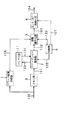
図1は、本発明の第1の実施の形態となる画像符号化装置の構成例を示すブロック図である。
【0015】
この図1に示する画像符号化装置は、入力された画像データ(入力画像)100を1ライン毎に書き込んで記憶するメモリ部6と、メモリ部6に蓄積された画像がウェーブレット変換に要するライン数に達する毎に水平・垂直方向のウェーブレット変換を施すウェーブレット変換部2と、ウェーブレット変換部2から得られたウェーブレット変換係数を量子化する係数量子化部3と、係数量子化部3から得られた量子化係数のサンプル数がエントロピー符号化に要する大きさに達したときにエントロピー符号化するエントロピー符号化部4とを有して構成され、係数量子化部3は、上記ウェーブレット変換の際に生成されたサブバンド毎に予め用意されたテーブルの重み係数と、画像を構成するブロック領域画像毎に求めた重み係数のいずれか、または両方を用いて量子化を行う。また、上記入力画像100は、画像を構成するブロック領域画像毎にブロック画像内の動き情報またはテキスチャの詳細度を分析するブロック画像分析部1にも入力されているが、このブロック画像分析部1については後述する。
【0016】
この図1に示す画像符号化装置において、入力画像100を最上位ラインから順番に1ライン毎に取り込んで、データ読み出しメモリ部6に入力する。メモリ部6に所定の(ウェーブレット変換に要するライン数分の)画像データが蓄積された時点で、ウェーブレット変換部2で水平・垂直方向へのウェーブレット変換フィルタ処理が施される。通常は、ウェーブレット変換のフィルタリングを行うのに用いるフィルタは複数タップのフィルタであり、このフィルタリングに必要なだけライン数が蓄積されれば、直ちに上記ウェーブレット変換フィルタ処理が実行できる。
【0017】
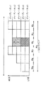
図2〜図5は、上記ウェーブレット変換及びウェーブレット分割処理、さらにエントロピー符号化の具体的な動作を説明するための図である。まず図2において、ステップS1に示すように、入力画像のデータライン21毎に上記図1のメモリ部6(図2のラインバッファ22)に読み込んで蓄積してゆき、ステップS2に示すように、ウェーブレット変換の垂直フィルタリングに必要なだけのライン数が蓄えられたならば、図1のウェーブレット変換部2で垂直フィルタリングを行い、続いて図3のステップS3に示すように水平フィルタリングを行う。ウェーブレット変換されて得られたウェーブレット変換係数はバッファ部11に蓄えられる。この時点で4つのサブバンド(LL,LH,HL,HH) のウェーブレット変換係数値が決定しており、ステップS4に示すように、高域側の3つのサブバンド(LH,HL,HH)の斜線部に示す量子化対象のサブバンド係数23に対して、図1の係数量子化部3による量子化を実行する。この時、制御部5から量子化実行の制御信号122が係数量子化部3に送信される。なお、各サブバンド(LL,LH,HL,HH) については、後で図6を参照しながら説明する。
【0018】
一方、最低域サブバンド(LL)のウェーブレット変換係数24は、再びバッファに蓄積され、これはステップS5に示すように垂直フィルタリングに必要なだけのライン数が蓄えられるまで継続する。従って、ウェーブレット変換部2からのウェーブレット変換係数120は上記の1ラインづつバッファ部11に送られて蓄積される。また、上記ステップS4の操作により、係数量子化部3で量子化が実行されて得られた量子化係数103(図3の量子化済みのサブバンド係数ライン25のデータ)は、エントロピー符号化部4に送られる。
【0019】
次に、上記最低域サブバンド(LL)について、バッファ部11内に垂直フィルタリングに必要なだけのライン数が蓄えられたならば、制御部5からウェーブレット変換実行の制御信号105がウェーブレット変換部2に送信され、ステップS6に示すように、次のウェーブレット分割ステージ生成のために、垂直フィルタリングに続いて、水平フィルタリングを実行する。この結果、図4のステップS7に示すように、最低域サブバンドの第2ステージの4つのサブバンドのウェーブレット変換係数値がここで確定するので、直ちに後段の量子化を行い、量子化係数を出力する。
【0020】
なお、上記図2のステップS2の操作のウェーブレット変換の垂直フィルタリングに必要なだけのライン数を蓄える場合(分割ステージ数が1の場合に相当)や、上記図3のステップS5の操作の垂直フィルタリングに必要なだけのライン数を蓄える場合(分割ステージ数が2の場合に相当)には、ウェーブレット変換係数を、図1のバッファ部11に記憶・保持しておく。この時、各分割ステージでの1ライン毎のウェーブレット変換係数120がバッファ部11に順番に送られ、ここで記憶される。
【0021】
一方、上記図3のステップS3の操作やステップS6の操作での、垂直フィルタリングの際には、上記バッファ部11に蓄積された必要なライン数分のウェーブレット変換係数121を、バッファ部11から読み出して、これらに垂直フィルタリングを掛ける。以上の動作をすべての分割ステージが終了するまで継続するわけであるが、途中でエントロピー符号化が可能となった量子化済みの係数に対して次に説明するようなエントロピー符号化を行うことも可能である。
【0022】
すなわち、図1の最後段に位置するエントロピー符号化部4でのエントロピー符号化は、一般に情報源符号化とも呼ばれ、データ列の出現分布の偏り等の特徴を利用して情報量を圧縮する技術であり、ハフマン符号化や算術符号化が広く使われている。データ列を入力して学習しながら符号化を行う手段は、予め決められたテーブルを用いるハフマン符号化よりも、入力データに適応化できる点で有利になる可能性がある。その場合、どの範囲内で入力データを取得するかが問題である。一般に対象となる入力データが多いほど有利であるが、画面内の特定領域に限定したい場合には、普通ある程度の大きさのブロック形状の範囲内で入力データを取得することになる。
【0023】
本実施の形態では、いずれの場合にも対応可能であるが、全画面分の量子化係数を保持してからエントロピー符号化する場合には、それら係数を全部記憶・保持する大きなメモリ(バッファ)が必要になる。従って、メモリ容量が少なくて済むブロックベースのエントロピー符号化について、以下に説明する。
【0024】
図3のステップS4や図4のステップS7によってウェーブレット変換係数の量子化が進み、図4のステップS8に示すように、第1分割ステージのサブバンド(HL,LH,HH)の量子化係数のライン数が、上述したブロックベースのエントロピー符号化の処理単位のブロックの高さ(H)に到達した時点で、制御部5からエントロピー符号化実行の制御信号107がエントロピー符号化部4に送信されて、エントロピー符号化単位28毎にエントロピー符号化を実行する。
【0025】
更に、同様にして、図5のステップS9に示すように、第2分割ステージのサブバンド(LL)の量子化係数のライン数が、ブロックベースのエントロピー符号化の処理単位のブロックの高さ(H)に到達した時点で、このエントロピー符号化単位28毎にエントロピー符号化を実行する。
【0026】
なお。図5のブロック29は、エントロピー符号化を実行済みの量子化係数のブロックを示す。
【0027】
以上の操作を必要なウェーブレット分割ステージまで繰り返し実行することで、全画面のウェーブレット変換と量子化+エントロピー符号化とを完了する。
【0028】
以上説明したような構成及び動作に加え、本発明の第1の実施の形態においては、上記ウェーブレット変換の際に生成されたサブバンド毎に予め用意されたテーブルの重み係数と、画像を構成するブロック領域画像毎に求めた重み係数のいずれか、または両方を用いて、量子化を行うようにしている。この場合の上記図1の係数量子化部3の具体的な構成とその動作について、以下説明する。
【0029】
通常のウェーブレット変換符号化器では、ウェーブレット変換係数を直接量子化する手段を取るが、ここでは量子化係数に重み係数を掛けることで、量子化係数の値を修正することを行う。
【0030】
例えば図6は、2次元のウェーブレット変換を示した図であり、レベル3まで2次元画像を帯域分割した結果得られる帯域成分を図示したものである。すなわち図6では、先ずレベル1の帯域分割(水平・垂直方向)により4つの成分LL、LH、HL、HHに分かれる。ここでLLは水平・垂直成分が共にLであること、LHは水平成分がHで垂直成分がLであることを意味している。次に、LL成分は再度帯域分割されて、LLLL、LLHL、LLLH、LLHHが生成される。さらに、LLLL成分は再度帯域分割されて、LLLLLL、LLLLHL、LLLLLH、LLLLHHが生成される。なお、このように、低域成分を階層的に分割する以外に、全帯域を均等に分割することも行われる。図6の例では、3レベルまでウェーブレット分割を行うことにより、合計10個のサブバンド(帯域)に分割されていることがわかる。これら10個のサブバンド毎に、例えば重み係数をTを乗算する。各サブバンド毎の重み係数Tとしては、低域側のLLLLLL成分から順に、TLLLLLL、TLLLLHL、TLLLLLH、TLLLLHH、TLLHL、TLLLH、TLLHH、TLH、THL、THHとしている。
【0031】
すなわち、例えば、レベル1の高域バンドであるHH成分のすべての変換係数には、係数THHの値を乗算する。同様にしてレベル1の他の帯域の成分の変換係数には、それぞれ係数TLH、THLを乗算する。一方LL成分はレベル2の分割で、さらに4つの帯域に分割されており、同様にして、各帯域毎に予め決められた重み係数値を、変換係数に乗算する。以上の動作を所定のウェーブレット分割レベルまで繰り返し行うことで、変換係数を修正する。この場合特に、サブバンド毎に重み係数を異なる値にすることが挙げられる。
【0032】
具体的には、低域成分の雑音、歪みは人間の目に付きやすいことから、低域のサブバンド用の重み係数(例えばTLLLLLLやTLLHL等)程、重みをかけて変換係数値が大きくなるように設定することが好ましい。
【0033】
次に、画像空間の特定ブロック領域毎に量子化係数に重み係数を掛けて、細かい制御を行う技術について説明する。図7、図8は、上記図1の係数量子化部3の具体的な構成例を示すものである。
【0034】
先ず、図7の係数量子化部は、図1のウェーブレット変換部2からのウェーブレット変換係数102が供給されるスカラ量子化部13と、スカラ量子化された量子化係数124が送られるブロック領域重み係数変更部14と、このブロック領域重み係数変更部14に上述したサブバンド別の重み係数125を送るサブバンド別重み係数テーブル15とを有して構成され、ブロック領域重み係数変更部14から最終的な量子化係数103が出力されて、図1のエントロピー符号化部4に送られる。また、高画質にしたいブロック領域を示す分析情報106が、上記図1のブロック画像分析部1によりブロック領域重み係数変更部14に送られるが、このブロック画像分析の詳細については後述する。
【0035】
すなわち、図7において、既に説明した図1のウェーブレット変換部2で生成されたウェーブレット変換係数102は、代表的な量子化手段であるスカラ量子化部13によって量子化され、得られた量子化係数124は、ブロック領域重み係数変更部14に送られる。他方、サブバンド別重み係数テーブル15からは上記図6と共に説明したようなサブバンド毎の重み係数125が出力される。この重み係数は、例えば、ウェーブレット分割ステージが大きくなる程、大きい値に設定されており、また逆に、分割ステージが小さくなる程、小さい値に設定されている。一方、ブロック領域の分析情報106を入力したブロック領域重み係数変更部14では、対象とするブロック領域に対する当該重み係数値を計算して、変更された量子化係数103をブロック領域重み係数変更部14より出力する。具体的な動作としては、所望のブロック領域を高画質にしたい場合には、重み係数を大きく設定する必要があることから、サブバンド毎の重み係数125を元に、サブバンド内の当該ブロック領域に相当する部分の係数を大きく設定する。
【0036】
すなわち、図9に示すように、画面を縦横3分割づつ9個のブロックに分割した場合の中央のブロックに相当する領域(図中の網線部)が上記高画質にしたいブロック領域だとすると、この部分を高画質にするためには、図6で示した同一サブバンド内であれば同じ重み係数Tという規則を超え、このTを元に、図9の該当領域(網線部)に対する重み係数値を変更することとする。例えば、サブバンドHL成分の重み係数値は図6よりTHLであるが、このサブバンドHL成分の中の該当領域P1 に対して、サブバンドHLに対する重み係数値THLに他よりも大きい値を乗算することで、図9のLH成分のサブバンド中の該当領域P1 の重み係数値は、それ以外の領域に比べ大きく設定されるので、このブロック領域の画質を向上させることができる。他のサブバンドの該当領域P1 、P2 、P3 に対しても、全く同様の操作を行えばよい。
【0037】
なお、上記のブロック領域の重み値に、サブバンド成分の重み係数値を乗算することで、当該ブロック領域の重み係数を決定し、この重み係数をスカラ量子化部13から送出されたスカラ量子化係数に乗算して、最終的な量子化係数103を決定して出力することもでき、このための構成の具体例を図8に示している。この図8では、ブロック領域の分析情報106がブロック領域重み算出部16に送られることで、ブロック領域重み123が算出されてブロック領域重み係数演算部17に送られる。このブロック領域重み係数演算部17では、ブロック領域重み123と、サブバンド別重み係数テーブル15からのサブバンド成分の重み係数値125とを乗算し、当該ブロック領域の重み係数を決定し、この重み係数をスカラ量子化部13から送出されたスカラ量子化係数124に乗算して、最終的な量子化係数103を出力する。
【0038】
ここで、スカラ量子化部13では、例えば下記の式1に示すようなスカラ量子化が行われる。すなわち、スカラ量子化出力Qは、
Q = x/Δ ・・・(式1)
となる。この式1において、xはウェーブレット変換係数値、Δは量子化インデックス値である。
【0039】
次に、上記図1のブロック画像分析部1及びブロック領域の分析情報106について説明する。図1のブロック画像分析部1では、ブロック領域画像毎の動き情報またはテキスチャの詳細度を分析する分析手段によって、例えばブロック領域画像内に、被写体の大きな動きがあるとかテキスチャの詳細度が高い等の情報を抽出する。具体的には、画像処理の分野で研究された成果を用いればよく、例えば動き検出では、1つ前のフレームとの差分を求め、予め設定した閾値よりも大きければ動き有りと判定し、後者ではブロック領域画像内のすべての画素値の分散値を採取し、これが閾値よりも大きい場合には、テキスチャの詳細度が高いと判断することができる。
【0040】
なお、上記第1の実施の形態では、ウェーブレット変換を垂直フィルタ、水平フィルタの順番で行っているが、その逆にしてもよいことは勿論である。ただし、当然であるが、データのバッファリングの方向は、水平と垂直とが逆になる。
【0041】
第2の実施の形態
以下、本発明の第2の実施の形態を説明する。この第2の実施の形態では、図1のエントロピー符号化部4として、ブロック内の量子化係数をバイナリデータから成るビットプレーンに分解して、各サブ・ビットプレーンのシンボルの出現確率分布に応じて算術符号化を行い、かつ確率分布の推定は予め決められたブロック内のデータに対してのみ行うものを用いている。
【0042】
ここで、ビットプレーンについて図10を用いて説明する。図10の(a)は、縦4、横4の16個の量子化係数を示しており、+13、−6等は量子化後の係数値を意味している。これらの量子化係数は、その絶対値と正負の符号(+−)とに分けられ、絶対値はMSBからLSBのビットプレーンに展開される。図10の(b)には絶対値の各ビットプレーンを示し、図10の(c)には符号のビットプレーンを示している。図10の(b)の絶対値の各ビットプレーン上の係数は、0か1のいずれかになり、図10の(c)の符号のビットプレーン上の係数は+、0、−のいずれかになる。図10の(b)、(c)の場合は、4つの絶対値ビットプレーンと1つの符号ビットプレーンから構成されている。従って、この後段処理として、ビットプレーン毎の2値の符号化、例えば算術符号化を行えばよい。以上が図1のエントロピー符号化部4での動作となる。
【0043】
なお、算術符号化とは、所定の範囲内で確率分布の推定を行いながら、符号化シンボルに数値を当てはめていく手法である。この確率分布の推定は、例えば図4で説明したように、予め決められたブロックの範囲内で行われる。これにより、エントロピー符号化の独立性が保たれる。
【0044】
第3の実施の形態
本発明の第3の実施の形態となる画像符号化装置について、図11を参照しながら説明する。この図11に示す画像符号化装置は、入力画像の全画面を蓄積する全画像メモリ部18と、全画面に対し水平・垂直方向のウェーブレット変換フィルタを掛ける全画像ウェーブレット変換部7と、画像を構成するある特定のブロック領域に対応したウェーブレット変換係数を抽出するブロック係数抽出部8と、抽出されたウェーブレット変換係数を量子化するブロック係数量子化部9と、生成された量子化係数のサンプル数が所定の大きさに達した時にエントロピー符号化を行うエントロピー符号化部4とを有して構成されている。
【0045】
既に説明した第1の実施の形態が、ウェーブレット変換をライン毎に行う構成であったのに対し、図11に示す第3の実施の形態は、全画面分のウェーブレット変換を1度に行い、ブロック毎に量子化・エントロピー符号化等の後段の処理を行う所に差異がある。
【0046】
図11において、入力画像100のすべてを全画像データ読み出しメモリ部18に入力し記憶する。続いて、全画像ウェーブレット変換部7は、制御部5からの制御信号105に従い、全画像データ108に対してウェーブレット変換の水平・垂直フィルタリングを行う。所定のウェーブレット分割数まで変換を行い、すべてのサブバンドの変換係数126を生成する。次に、変換係数バッファ部19は、1次的に変換係数126を記憶・保持するバッファの役割を果たす。
【0047】
ブロック係数抽出部8では、制御部5からの制御信号112に従い、変換係数バッファ部19に蓄えられた全変換係数の中から、符号化対象のブロック領域に相当するすべてのサブバンドの変換係数109を抽出して読み出す。なお、部分領域のサブバンドについては、既に図9と共に説明した通り(図中の網線部)である。ブロック係数抽出部8からの変換係数110は、次にブロック係数量子化部9において量子化が行なわれる。
【0048】
一方、上記第1の実施の形態において説明したように、ブロック画像分析部1からは、画面を構成する矩形のブロック領域画像毎の動き情報・テキスチャ情報を含む分析情報106が送出される。これを受けて、ブロック係数量子化部9では、現在の符号化対象ブロックの分析情報106を参照して、ブロック毎に量子化を行う。この具体的な動作については、既に第1の実施の形態において、図7、図8と共に説明した通りであり、所定のブロック画像を高画質にする場合には重み係数を大きく設定し、この値に図6と共に説明した各サブバンド毎の重み係数テーブル値を演算して、更にスカラ量子化係数にこの演算値を乗算すればよい。
【0049】
以上により、符号化ブロック毎に、きめ細かな量子化制御ができるので、結果として画質制御が適応的に実現される利点がある。
【0050】
上記操作によって最終的に得られたブロックの量子化係数111は、上記第1の実施の形態で説明したように、エントロピー符号化部4において、制御信号5に従い、エントロピー符号化が行なわれ、符号化ビットストリーム113とされて送出される。また上記第2の実施の形態で述べたビットプレーンを用いたエントロピー符号化を適用することも可能である。
【0051】
この第3の実施の形態では、画面を1度にバッファリング、更にウェーブレット変換し、後段ではブロック毎に量子化、エントロピー符号化を行なう構成になっており、実施形態1の構成に比べ、画像の読み出しが1回で済む利点がある一方、必要とするバッファ容量が大きくなる点に留意すべきである。
【0052】
第4の実施の形態
本発明の第4の実施の形態は、ウェーブレット変換符号化器の前段部に、入力画像を複数個の矩形形状のタイルに分割するタイル分割手段を備え、各タイル画像内の画像データをメモリに読み出して、後段の符号化手段を備えたものである。この第4の実施の形態の画像符号化装置の構成例を図12に示す。この図12に示す画像符号化装置は、上記図1の画像符号化装置の前段部にタイル分割部10を設けている点が異なっており、他は上記図1と同様であるため説明を省略する。
【0053】
ここで図13は、原画像を複数個のタイルに分割して、各々のタイルにウェーブレット変換を施す動作を説明するための図である。図中、実線は実際のタイルの境界を示し、破線は、後述のウェーブレット変換のフィルタリングの際に、隣接タイルまでにフィルタリングが及ぶ境界を示している。
【0054】
すなわち、図13の(A)に示す原画像を、図13の(B)に示すように複数個のタイルに分割し、それぞれのタイル毎に、図13の(C)の破線に示す境界までの範囲でウェーブレット変換のフィルタリングを施し、符号化ビットストリームを生成している。
【0055】
図12において、タイル分割部10からの各タイル画像114を、ブロック画像分析部1に入力しており、このブロック画像分析部1では、既に述べた技術により分析情報115を得て出力する。ここで注意すべき事としては、タイル画像114と上述したブロック画像とは必ずしも同一のものである必要は無いことである。すなわち、タイルの中に複数個のブロックが存在していてもよい。一般には、タイルのサイズの方が、ブロックのサイズよりも大きく設定される。ただし、符号化等の処理を簡略化するために、これらのサイズは一般に2のべき乗の比率に設定されることが多い。
【0056】
また、図12のタイル分割部10からのタイル画像114は、メモリ部6に記憶・保持される。上記第1の実施の形態で説明したように、1ライン毎に画像データを読み出してバッファリングし、更にウェーブレット変換する場合には、メモリ部6では、タイル画像114内を1ラインずつ読み出してこれを蓄積する。一方、上記第3の実施の形態で述べたような全画面を1度にバッファリングする場合には、メモリ部6には当該タイル画像114内のすべての画像データが蓄積される。本第4の実施の形態は、上記いずれの場合にも対応することができ、この場合、後段のウェーブレット変換部11以降での動作は、それぞれの実施の形態で説明した通りである。
【0057】
メモリ部6から送出された画像データ116は、タイルベースウェーブレット変換部11で、制御部5からの制御信号105に従い、ウェーブレット変換が施され、変換係数117が出力される。変換係数117は、係数量子化部3において量子化されて、量子化係数118がエントロピー符号化部4に送出される。エントロピー符号化部4では、制御部5からの制御信号105に従い、エントロピー符号化を行い、エントロピー符号化部4からは符号化ビットストリーム119が送出される。このとき、ブロック画像分析部1からの分析情報115を用いて、係数量子化をブロック毎に適応的に行う動作は、既に述べた実施の形態と同様である。
【0058】
第5の実施の形態
この第5の実施の形態は、上記第4の実施の形態におけるタイル画像のウェーブレット変換の際の、隣接タイルまでのフィルタリング動作を具体化したものである。
【0059】
上述のようなタイル毎にウェーブレット変換を施す場合には、符号化対象以外のタイルについても考慮に入れる必要がある。すなわち、上記各タイル毎にウェーブレット変換を行う場合に、フィルタのタップ長分だけタイルの周囲画素にもフィルタリングが及ぶため、隣接タイルとの間でオーバーラップさせながらフィルタリングを行うことになる。このように、フィルタリングの影響が及ぶ範囲まで隣接タイルの画素を読み出してウェーブレット変換するような、オーバーラップ型のタイルベース・ウェーブレット変換について、図14を参照しながら説明する。
【0060】
図14は、オーバーラップ型のタイルベース・ウェーブレット変換を行う際の、符号化対象のタイル(ブロック)RT とフィルタリングの及ぶ範囲RF とを示している。この図14中の a,b,c,d,e,f、h,i,j,k,l,m はすべて画素を表す。例えば画素cを水平方向にフィルタリングする時に、d,e,f の3画素を右隣りのタイル画像から読み出して、これらに所定のフィルタ係数を畳み込み演算する。同様に例えば、画素jを垂直方向にフィルタリングする時に、k,l,m の3画素を下のタイル画像から読み出して、これらに所定のフィルタ係数を畳み込み演算する。
【0061】
従って、この第5の実施の形態におけるタイル分割部では、フレーム画像を複数のタイルに分割すると共に、タイルの周囲に、ウェーブレット変換手段によるフィルタリングの影響が及ぶ範囲まで、隣接タイルの画素を読み出すことで、符号化対象領域を拡大する。この際、符号化対象タイルの外部のフィルタリングの及ぶ範囲の画素をどのように得るかが問題となる。
【0062】
この第5の実施の形態では、隣接するタイルの画像間にオーバーラップする領域を設けず、タイル外部でフィルタリングの及ぶ範囲内ではタイル内部のウェーブレット変換係数を対称拡張して畳み込み演算するようにしている。これを示したものが図15及び図16であり、図15はタイル周辺の具体例を、図16は原画像が対称拡張の畳み込み演算を施しながらウェーブレット分割を行っていく過程を、それぞれ示している。
【0063】
すなわち、図15は、この対象拡張を具体的に図示したものであり、符号化又は復号対象のタイルの領域RT 内の水平方向のc, b, a の画素列が、タイル境界を境にして、対称的にa, b, c の並び順に、フィルタリングの及ぶ範囲RF まで拡張されていることがわかる。同様に、垂直方向では、タイル領域RT 内のf, e, d の画素列が、タイル境界を境にして、対称的にd, e, f の並びにフィルタリングの及ぶ範囲RF まで拡張される。このような鏡像関係の対称拡張を行えば、タイル画像内部の画素数と同数だけしかウェーブレット変換係数が生成されないことが知られている。すなわち、冗長度が無い利点がある。
【0064】
次に図16は、対称畳み込みによるウェーブレット符号化の概念を説明するための図であり、この図16の(A)に示す原画像は、(B)に示すようにタイル画像に分割された後、各タイル画像毎に(C)の破線に示すフィルタ処理が及ぶ範囲まで、タイル外の領域に画素の対称拡張を行う。
【0065】
続いて、図16の(C)の対称拡張された各タイルに対して、WT(ウェーブレット変換)を掛ける。その結果、既に説明したように、例えば4つの帯域成分に分割される(図16の(D)参照)。図16の(D)中の斜線部は、上述した低域のLL成分である。さらに、この斜線部の低域成分(LL)のタイルは、図16の(E)に示すように、同様に対称拡張を行い、ウェーブレット変換(WT)が施される。以後同様の操作が、所定のウェーブレット分割数まで繰り返される。以上が、この第5の実施の形態のタイル分割部及びウェーブレット変換部での、タイル毎の対称拡張を伴うウェーブレット変換の動作説明である。
【0066】
第6の実施の形態
本発明の第6の実施の形態は、各タイル毎のウェーブレット変換の際に、タイルの外側でフィルタリングが及ぶ範囲内の画素を、タイル境界上の画素値と点対称の関係になるように対称拡張することで、タイル外部の符号化対象画素を拡張している。
【0067】
図17はこれを図示したものであり、図17中の(a)と(b)との2つの例を示している。図中、X[0],X[1],X[2],X[3],X[4],X[5],X[6],X[7] の8個のサンプル点はタイル内の画素(1次元方向のみ)を示している。
【0068】
一方、点線で示したサンプル点の画素は、X[0] 又はX[7] の画素値を点対称の基準値として算出される。図17の(a)の場合では、タイル境界のサンプル点X[0] のサンプル位置での画素値を示す点Pa を点対称の基準点としており、例えば、タイル外部のサンプル点x[1] は、タイル内で点対称の位置関係のサンプル点X[1] から基準点Pa を通るように伸ばした延長線上の等距離の点を算出することで得られる。すなわち、基準点Pa を中心として、サンプル点x[1] はサンプル点X[1] の点対称の位置にある。同様に、基準点Pa を中心として、サンプル点x[2] はサンプル点X[2] の点対称の位置にあり、サンプル点x[3] はサンプル点X[3] の点対称の位置にある。タイルの他方の境界でのX[7] のサンプル点での画素値を点対称の基準点とする場合も同様である。
【0069】
次に、図17の(b)の場合について説明する。図17の(a)の場合との相違点は、点対称の中心となる基準点Pb を、サンプル位置に対して半サンプル分の距離だけずらしていることである。すなわち、タイル境界のサンプル点X[0] のサンプル位置をタイル外部に半サンプル分の距離だけずらした位置における、サンプル点X[0] に等しい画素値を示す点Pb を、点対称の基準点としている。従って、サンプル点X[0] からタイル外部に1サンプル分だけ離れた位置のサンプル点x[0] は、基準点Pb を中心としてサンプル点X[0] の点対称の位置にあることから、サンプル点X[0] と同じ値となる。これにより、タイル境界の内部の点(例えばX[0])と外部の点(例えばx[0])の各値が同一となり、タイル境界での接続を滑らかにすることができる。
【0070】
以上、図17の(a)または(b)に示すいずれかの手法によって、点対称関係を用いて画素拡張を行うことにより、隣接タイルの画素値を用いずに、タイル内部の画素値をタイル外部でウェーブレット変換によるフィルタリングが行われる範囲まで拡大して、畳み込み演算を行うことができる。
【0071】
第7の実施の形態
本発明の第7の実施の形態について説明する。この第7の実施の形態では、タイルの外側でフィルタリングが及ぶ範囲内の画素の一部だけを抽出して、畳み込み演算するようにしている。
【0072】
すなわち、上記第5、第6の実施の形態では、いずれもフィルタリングの及ぶ範囲内の画素をすべて求めていたが、本第7の実施の形態では、この一部だけを抽出するようにしている。このように、フィルタリングが及ぶ範囲内の画素の一部だけを抽出することにすれば、畳み込み演算の回数が削減される利点がある。他方、タイル境界部での画質劣化(不連続性)が発生する可能性があるが、比較的符号化ビットレートが高い場合には大きな差異は発生しない。
【0073】
第8の実施の形態
本発明の第8の実施の形態は、既に述べたブロック毎の量子化制御の別の形態を提案するもので、構成は上記図1と同様でよいが、係数量子化部3での動作が異なっている。ここではまず、ウェーブレット変換部2で生成されたウェーブレット変換係数を、既に述べたスカラ量子化で量子化して得られた量子化係数を、MSBからLSBまでのビットプレーンに分解する。なお、ビットプレーンの概念については、上記図10と共に説明した通りであり、説明を省略する。
【0074】
係数量子化部3での動作として、通常の場合には、上記第2の実施の形態で説明したように、上記ビットプレーンのMSBからLSBの方向に、各ビットプレーン単位でバイナリデータをエントロピー符号化することになる。しかし本第8の実施の形態では、同一サブバンド内に存在する複数個のサブバンド分割されたブロックのビットプレーンを所定のビット数分だけシフト操作した後、新たに生成されたビットプレーンをエントロピー符号化する手段を取る。
【0075】
以下、図18を参照しながら具体的に説明する。図18の(A)は、画像をウェーブレット分割してできたあるサブバンドを示しており、破線で区切られた縦横6個、計36個のブロックは、後段のエントロピー符号化を行うブロックの単位であると仮定する。一方、図18の(B)は、上図のサブバンド内のビットプレーンの断面図(実際は2次元であるが、これを1次元化したもの)である。この図18の(B)では、エントロピー符号化単位の幅をWで示している。図18の(A)のサブバンド内の網線領域が、下図の斜線領域のビットプレーンに対応している。図18の(B)の縦軸は、MSBからLSBのビットプレーンの深さを示している。
【0076】
ところで、原画像の画面中の1つのブロック領域は、上記図6や図と共に説明したように、1つ分割ステージが増える毎に、縦横のサイズが1/2倍になる。すなわち、図9のブロック領域P(網線部分)については、第1レベルのブロック領域P1 の縦横のサイズの1/2が第2のレベルのブロック領域P2 の縦横のサイズとなり、一般に、
(Pn+1の縦横サイズ)=(Pnの縦横サイズ)/2
となる。よって、画像の特定領域をウェーブレット分割してできた、あるサブバンドのブロックと、上記エントロピー符号化のブロックとの大小関係を考える必要がある。
【0077】
ここで、図19の(A)に示すように、画像の特定領域(図中の網線部分)のサブバンドブロックのサイズWS が、エントロピー符号化ブロックのサイズWE よりも小さい場合、すなわち、WS <WE の場合は、画像の特定領域のサブバンドブロックに相当するビットプレーンをMSB方向にシフトアップ(Shift-up)するか、またはLSB方向にシフトダウン(Shift-down)するかの操作を行う。更に、該エントロピー符号化ブロック内のすべてのサブバンド・ブロックのシフト操作が終了した後で、新たに生成されたビットプレーンに対しエントロピー符号化の操作を行う。なお、シフトアップ(Shift-up)操作は、当該ブロック領域の画質向上に寄与し、シフトダウン(Shift-down)操作は逆に画質低下をもたらす。これによって画質制御を実現できる。
【0078】
また、上記対象ブロック領域以外に存在するエントロピー符号化ブロックに対して、ビットプレーンのシフトダウン(Shift-down)操作を行っても良く、上述した場合と同等の効果を奏することは明らかである。なお、デコーダ側ではこのシフト(Shift)の逆操作が必要であり、このビットシフト値は符号化ビットストリーム中に書き込む必要がある。
【0079】
これに対して、図19の(B)は、画像の特定領域のサブバンドブロックのサイズWS が、エントロピー符号化ブロックのサイズWE よりも大きいか等しい場合、すなわち、WS ≧WE の場合を示している。この場合、サブバンド分割ブロックのビットシフト操作が終了した後、そのサブバンド分割ブロック内に存在するすべてのエントロピー符号化単位ブロックをビットプレーン符号化する。
【0080】
第9の実施の形態
本発明の第9の実施の形態に係る画像符号化装置は、入力画像をライン毎にメモリ手段に書き込んで蓄積し、メモリ手段に蓄積された画像がウェーブレット変換に要するライン数に達する毎に水平・垂直方向のウェーブレット変換を施し、ウェーブレット変換により得られたウェーブレット変換係数を量子化し、得られた量子化係数をMSBからLSBまでのビットプレーンに分解し、上記量子化係数のサンプル数が所定の大きさに達した時にエントロピー符号化を行うものであり、さらに、エントロピー符号化の際には、同一サブバンド内に存在する複数個のエントロピー符号化ブロックのビットプレーンにおいて、MSBからLSBのビットプレーンの一部分を分割・抽出し、抽出された部分ビットプレーンをMSBからLSBに向かって符号化を行った後、上記部分ビットプレーンに相当する部分符号化ビットストリームを生成するようにしたものである。
【0081】
この第9の実施の形態は、量子化係数をMSBからLSBまでのビットプレーンに分解するまでの動作は、上記第8の実施の形態と同様である。ここで、上記第8の実施の形態では、エントロピー符号化ブロック毎に、MSBからLSBの方向に1枚づつのビットプレーンを順番にエントロピー符号化する手段を取っていた。従って各エントロピー符号化ブロックは独立していた。他方、本第9の実施の形態では、同一サブバンド内に存在するすべてのエントロピー符号化ブロックのビットプレーンに跨って符号化を行う。以下、図20を参照しながら具体的な動作を説明する。
【0082】
図20は、上記図18の(B)と同様に、サブバンド内のエントロピー符号化ブロックのビットプレーンの断面(1次元)を示す図である。この図20において、サブバンドブロックのサイズをWS で、エントロピー符号化ブロックのサイズをWE でそれぞれ示しており、斜線領域のブロックを2ビットだけシフトアップ(Shift-up)したことを示している。このシフトアップ(Shift-up)操作により、網線領域のビットプレーンが新たに生成されている。その結果、同サブバンド内に存在するすべてのエントロピー符号化ブロックを、MSB(図20ではビットプレーンBp1)からLSB(ビットプレーンBp2)まで、1ビットプレーンずつエントロピー符号化した場合、前記シフト操作により最初のビットプレーンの配置とは異なったものになるため、符号化されるビットプレーンの順番が、エントロピー符号化ブロックによって異なってくる。
【0083】
ここで、サブバンド分割されたブロックのビットプレーンを、所定のビット数分だけシフト操作した後で、同一サブバンド内に存在するすべてのエントロピー符号化ブロックのMSBからLSBの方向に、1ビットプレーンずつ順次符号化を行うことが挙げられる。
【0084】
なお、本実施の形態によれば、復号化器側ではMSBからLSBに順番に復号化していくことで、解像度が一定で画質が如序に、段階的に向上する画質スケラビリティ復号を実現することができる。これは、回線速度の限定されているインターネットや、無線等の回線での使用では効果を発揮する。
【0085】
また、上記サブバンド分割されたブロックは、元来入力画像の特定の空間画像領域をウェーブレット分割して生成されたものであるが、このブロック情報は、画像を構成する空間ブロック領域画像毎に、ブロック画像内の動き情報またはテキスチャの詳細度を分析する分析手段によって供することができる。
【0086】
なお、既に述べた通り、各ビットプレーンに分割した時、各ビットプレーンは0と1の絶対値データと正負を示す符号とに分類できる。従ってこれらの絶対値データと符号とを算術符号化することで高い圧縮率を実現することができる。
【0087】
第10の実施の形態
この第10の実施の形態は、上記第9の実施の形態を拡張したものである。すなわち、すでに説明したように、上記第9の実施の形態では、サブバンド毎に独立して、MSBからLSBへのビットプレーン符号化を行っていた。しかし、画像においては、一般に低域成分により大きなエネルギーが集中しており、低域サブバンドを高域サブバンドよりも重視することで、同じビットレートでも主観画質が優れたものを供することが期待できる。
【0088】
本第10の実施の形態では、このような考えに基づき、符号化ビットストリームを、最も分割ステージ数の多い最低域のサブバンドから、最も分割ステージ数の少ない最高域のサブバンドの方向に、エントロピー符号化ブロックの符号化ビットストリームを並べる手段を取ることにより、同一ビットレートでの主観画質を向上させることができる。また復号化器側では、本実施形態の手段により生成された符号化ビットストリームを復号して行くに従い、復号画像の解像度が段階的に大きくなるスケラビリティ復号を実現することができる。
【0089】
第11の実施の形態
この第11の実施の形態においては、入力画像がインターレース画像で、上記ブロック画像分析部から分析情報によって、対象ブロックの中の動きが大きいと判断されたブロックに対しては、上述したようなシフトアップ手段を用いて、対象ブロック領域のビットプレーンのシフトを行う。
【0090】
ここで、インターレース画像について、図21を参照しながら説明する。現在我々が親しんでいるテレビ放送は、飛び越し走査を用いたインターレース画像であり、奇数フィールドと偶数フィールドから構成されている。図21はこれを図示したものあり、図中のラインLa1,La2,・・・が奇数フィールド、斜線で示すラインLb1,Lb2,・・・が偶数フィールドを意味している。
【0091】
インターレース画像は、図21の左のフレーム(Frame) 構造のように、奇数フィールドと偶数フィールドとが1ライン毎に交互に並べられており、これをフレーム画像のまま符号化すると効率が落ちる場合がある。すなわち、インターレース画像のフレーム(Frame) 画像の場合に、被写体の動きが大きいと、奇数フィールドと偶数フィールドとの時間差があるために、図21の左のフレーム(Frame) 構造のように奇数フィールドと偶数フィールドとの画像の間に、ずれが生じて見える。これが後段の符号化を行う際の効率の低下に繋がる。一方、図21の右のフィールド(Field) 構造に分けることにより、ライン毎のずれは無くなり効率の低下は防げる。
【0092】
従って、図21の左図のまま(Frame構造のまま)符号化する場合には、ブロック内の画質を向上させるのが得策である。なお、上記分析情報とは、既に第1の実施の形態等で説明した図1のブロック画像分析部1からの分析情報106を用いることができる。
【0093】
第12の実施の形態
この第12の実施の形態は、上述したような分析情報によって静止領域と判断されたエントロピー符号化対象ブロックについては、上記シフトアップ手段を用いて、エントロピー符号化対象ブロック領域のビットプレーンのシフトを行うようにしたものである。これは、静止領域は一般に人間の目につきやすく、静止領域での画質劣化は比較的検知され易いことを考慮したものであり、このブロック領域のビットプレーンのシフトアップを行って画質を向上させることができる。
【0094】
第13の実施の形態
この第13の実施の形態は、上述したようにタイル分割してウェーブレット変換符号化を行う場合に、各タイル画像の符号化処理を、並列処理によって高速化したものである。すなわち、上記第4の実施の形態で述べたように、画面を分割したタイルはそれぞれ独立して符号化することができるので、各タイル画像の符号化処理を、並列処理すれば、高速に符号化が完了できる。例えば、複数のCPUを搭載したLSI(大規模集積回路)やコンピュータシステム等では、各CPU1個に対して、1個のタイル画像の符号化処理を割り当て、順次タイル符号化を行なう構成を取ればよい。
【0095】
第14の実施の形態
本発明の第14の実施の形態について説明する。これまでに述べた実施の形態はすべて静止画の符号化手段に関するものであったが、静止画を連続させると動画になることから、上記符号化技術は動画符号化としても応用できることは自明である。その際、連続した動画像フレームを1フレームずつ分ける手段が必要になる。一般に、NTSC信号の場合にはアナログからデジタルへのAD変換処理を行い、デジタル信号の動画像を1フレームずつ、バッファに蓄積する構成を採用する。その後、各フレーム単位に、既に述べた静止画符号化手段によって符号化を行えばよい。
【0096】
また、複数フレーム分だけ画像をバッファリングしてから、同該ウェーブレット変換符号化を行う構成にすることもできるが、この場合はより多くのメモリ容量を必要とする。
【0097】
第15の実施の形態
この第15の実施の形態では、既に述べた手段で量子化係数をエントロピー符号化ブロック毎に符号化する際、エントロピー符号化ブロックのビットプレーンは、MSBからLSBに至るプレーン数だけ存在するが、これらの各ビットプレーンを符号化する際、各ビットプレーンを複数個のサブ・ビットプレーンに分解するようにしている。
【0098】
図22はこれを図示したものであり、例えばMSBに相当するビットプレーンは、3つのサブ・ビットプレーンSB1,SB2,SB3から構成されている。他方、その下方(下位側)のビットプレーンでは、4つのサブ・ビットプレーンSB1,SB2,SB3,SB4から構成されている。このサブ・ビットプレーンはそれぞれ別の符号化パスの処理を行い、これは任意に設定することができる。すなわち0と1のバイナリデータから成るデータ系列の分布情報から最適な算術符号化の統計データを推定しながら、符号化することが効率的であり、同手段に関しては既に学会論文等で公知になっている技術を使えばよい。
【0099】
ここで、上記JPEG2000規格のエントロピー符号化では、3つの符号化パスが規定されており、3つの符号化パスを全て用いれば圧縮効率は最も高くなるが演算量あるいは処理時間が嵩み、符号化パスの数が少ないほど圧縮効率は低下するが演算量あるいは処理時間が短くなり、符号化パスの数を0とするときはエントロピー符号化を行わず(処理量0)、元の量子化係数データをそのまま出力することになる。このような符号化パスを上記各サブ・ビットプレーン毎に独立に選択するわけである。
【0100】
次に、上記サブ・ビットプレーンの符号化パスが、そのサブ・ビットプレーンが存在する母体のエントロピー符号化ブロック毎に取捨選択される手段について説明する。この選択手段の基準については、後述の実施の形態で説明する。
【0101】
第16の実施の形態
この第16の実施の形態では、取捨選択されるそのサブ・ビットプレーンの符号化パスがビットプレーン毎に可変になる手段について説明する。これは、図22において、MSBのビットプレーンに存在する3個のサブ・ビットプレーンSB1,SB2,SB3は、全ての符号化パスの処理を行うのに対し、下方向(下位側)のビットプレーンに存在する4個のサブ・ビットプレーンSB1,SB2,SB3,SB4は、例えばその内の2個しか処理しない、というような取捨選択を行うことにより、画像の劣化を抑えながら符号化効率を高めるものである。
【0102】
これは、画像の画質に与える影響は、MSBの方がLSBよりも大きく、有意な係数であるからに他ならない。従って、符号化ビット数を削減する手段として、上記MSBのビットプレーンに存在するサブ・ビットプレーンSB1,SB2,SB3の符号化パスの処理を優先して行い、他方LSB方向のビットプレーンに存在するサブ・ビットプレーンSB1,SB2,SB3,SB4の符号化パスの幾つかまたはすべてを省略することが有効である。
【0103】
第17の実施の形態
この第17の実施の形態では、取捨選択されるそのサブ・ビットプレーンの符号化パスが、そのサブ・ビットプレーンが存在するサブバンドの帯域によって可変になることを示す。
【0104】
例えば、図23は、ウェーブレット変換を3ステージ行った結果生成される各サブバンドを示している。例えば、そのサブ・ビットプレーンのビットプレーンが存在する帯域がLL-0(最低域)の場合には、そのサブ・ビットプレーンの符号化パスを優先して処理を行い、他方HH-3のように高域に存在する場合には、優先度を最も低くして、符号化パスの一部またはすべてを省略する。
【0105】
上記操作を、画像の特定領域に相当するサブバンドに相当する符号化ブロック毎に取り行うことで、同該画像の特定領域に個別に対応した画質制御を実現することができる。
【0106】
第18の実施の形態
この第18の実施の形態では、低域のサブバンドのエントロピー符号化ブロックは、高域のサブバンドのエントロピー符号化ブロックよりも、多数のビットプレーンを符号化するようにしている。
【0107】
すなわち、図23での低域LL-0のサブバンドのエントロピー符号化ブロックは、優先して多数または存在するMSBからLSBに至るすべてのビットプレーンを符号化するのに対し、高域のサブバンドのエントロピー符号化ブロックほど、符号化するビットプレーンを少なくするまたは省略するものである。
【0108】
これによって、画像のエネルギーが集中している低域バンドほど、優先度を高くして符号化ビットプレーンを多く符号化するので、低域が重視された画像を供することが可能になる。また、上記操作を、画像の特定領域に相当するサブバンドに相当する符号化ブロック毎に取り行うことで、該画像の特定領域に個別に対応した画質制御を実現することができる。
【0109】
第19の実施の形態
この第19の実施の形態では、低域のサブバンドのエントロピー符号化ブロックは、高域のサブバンドのエントロピー符号化ブロックよりも、各ビットプレーンの符号化において、多くのサブ・ビットプレーンの符号化パスを処理するようにしている。
【0110】
すなわち、図23で示したように、最低域LL-0のサブバンドに存在するエントロピー符号化ブロックは、図22のMSBからLSBに至る各ビットプレーンに存在するサブ・ビットプレーンの符号化パスの多くを、またはすべてを処理する。他方、最高域HH-3に向かって高域になるほど、各ビットプレーンの符号化において、サブ・ビットプレーンの符号化パスを削減する。
【0111】
また、この第19の実施の形態を、上述した第16の実施の形態で述べたMSB方向の符号化パスを重視した技術と組み合わせることも可能であり、それによってより一層細かい画質制御を実現することができる。また、上記操作を、画像の特定領域に相当するサブバンドに相当する符号化ブロック毎に取り行うことで、同該画像の特定領域に個別に対応した画質制御を実現することができる。
【0112】
一方、上記第15の実施の形態における量子化係数に、上記第1の実施の形態において説明した重み係数の乗算を施すことも可能である。この場合、既に重要な画像領域に相当するサブバンドの量子化係数には、上記第1の実施の形態で述べた重み係数が乗算されているので、その結果MSB方向に係数の分布が片寄る。従って、上記第16の実施の形態で述べたMSBからLSBに至るビットプレーン毎のサブ・ビットプレーンの符号化パスの増減の制御を行っても、MSB方向が優先される結果、その画像領域の画質は維持されることになる。
【0113】
これらの第15乃至第19の実施の形態によれば、特定画像領域のサブバンド中に存在するエントロピー符号化ブロック毎に、MSBからLSBに至るビットプレーンの増減、MSBからLSBに至るビットプレーン毎のサブ・ビットプレーンの符号化パスの増減、低域から高域へのサブ・ビットプレーンの符号化パスの増減の手段を使い分けることで、画質制御をきめ細かく実現でき、高画質を維持できる。
【0114】
以上説明したような本発明の各実施の形態の具体的な応用例としては、電子カメラ、ビデオカメラ、監視画像用ビデオコーデック(CODEC:符号化・復号器)、放送用VTRのコーデック、携帯・移動体画像送受信端末(PDA)、プリンタ、衛星画像・医療用画像等のコーデックまたはそのソフトウェアモジュール、ゲーム、3次元CGで用いるテキスチャの圧縮・伸長器またはそのソフトウェアモジュール等が挙げられる。
【0115】
なお、本発明は上述した実施の形態のみに限定されるものではなく、本発明の要旨を逸脱しない範囲において種々の変更が可能であることは勿論である。
【0116】
【発明の効果】
本発明によれば、入力画像をライン毎にメモリ手段に書き込んで蓄積し、上記メモリ手段に蓄積された画像がウェーブレット変換に要するライン数に達する毎に水平・垂直方向のウェーブレット変換を施し、上記ウェーブレット変換工程により得られたウェーブレット変換係数を量子化し、得られた量子化係数のサンプル数がエントロピー符号化に要する大きさに達したときにエントロピー符号化するようにし、上記量子化の際には、上記ウェーブレット変換の際に生成されたサブバンド毎に予め用意されたテーブルの重み係数と、画像を構成するブロック領域画像毎に求めた重み係数との少なくとも一方を用いて、量子化を行うようにしているため、画像のブロック単位での細かい画像制御が行え、画質の向上及び符号化効率の向上が図れる。
【0117】
また、本発明によれば、入力画像をライン毎にメモリ手段書き込んで蓄積し、上記メモリ手段に蓄積された画像がウェーブレット変換に要するライン数に達する毎に水平・垂直方向のウェーブレット変換を施し、得られたウェーブレット変換係数を量子化し、上記入力画像のブロック領域毎にブロック画像内の動き情報又はテキスチャの詳細度を分析し、上記量子化により得られた量子化係数のサンプル数がエントロピー符号化に要する大きさに達したときにエントロピー符号化することにより、ブロック画像内の動き情報又はテキスチャの詳細度に応じてブロック単位での画像制御が行え、画質及び符号化効率の向上が図れる。
【0118】
また、本発明によれば、入力画像をライン毎にメモリ手段に書き込んで蓄積し、上記メモリ手段に蓄積された画像がウェーブレット変換に要するライン数に達する毎に水平・垂直方向のウェーブレット変換を施し、得られたウェーブレット変換係数を量子化し、得られた量子化係数をMSBからLSBまでのビットプレーンに分解し、同一サブバンド内に存在する複数個のサブバンド分割されたブロックのビットプレーンを、所定のビット数分だけシフトし、シフト操作された量子化係数のサンプル数が所定の大きさに達した時に、エントロピー符号化ブロック毎に順番に、当該エントロピー符号化ブロックのビットプレーンをエントロピー符号化することにより、ブロック単位で量子化制御が行える。
【0119】
さらに、本発明は、入力画像をライン毎にメモリ手段に書き込んで蓄積し、上記メモリ手段に蓄積された画像がウェーブレット変換に要するライン数に達する毎に水平・垂直方向のウェーブレット変換を施し、上記ウェーブレット変換工程により得られたウェーブレット変換係数を量子化し、得られた量子化係数をMSBからLSBまでのビットプレーンに分解し、上記量子化係数のサンプル数が所定の大きさに達した時にエントロピー符号化を行ようにし、上記エントロピー符号化の際には、同一サブバンド内に存在する複数個のエントロピー符号化ブロックのビットプレーンにおいて、MSBからLSBのビットプレーンの一部分を分割・抽出し、抽出された部分ビットプレーンをMSBからLSBに向かって符号化を行った後、上記部分ビットプレーンに相当する部分符号化ビットストリームを生成することにより、量子化制御が実現できるので、画質制御が正確に行える。
【0120】
すなわち、本発明によれば、画面を構成する空間ブロックの分析情報に応じて、同ブロックをウェーブレット変換して生成されたサブバンド内の係数を操作することで、最適な量子化制御ができるので、これまで困難とされてきた部分領域毎の画質制御をウェーブレット変換符号化装置で実現できる。
【0121】
また、本発明によれば、上記量子化制御において、予め用意されたサブバンド毎の重み係数を量子化係数に乗算する他、量子化係数をビットプレーンに分解し、同ビットプレーンをMSBからLSBの方向に符号化する順番を、エントロピー符号化ブロック毎に可変にすることで、量子化制御が実現でき、これによって画質制御が正確に行える。
【0122】
また、本発明によれば、複数フレーム対応の動画像符号化装置に応用することもできるので、1つの符号化器で静止画・動画に対応できる、安価な装置の提供が可能になる。
【図面の簡単な説明】
【図1】本発明の第1の実施の形態としての画像符号化装置の概略構成を示すブロック図である。
【図2】ウェーブレット変換符号化の動作を説明するための図である。
【図3】ウェーブレット変換符号化の図2に続く動作を説明するための図である。
【図4】ウェーブレット変換符号化の図3に続く動作を説明するための図である。
【図5】ウェーブレット変換符号化の図4に続く動作を説明するための図である。
【図6】2次元画像の帯域分割(分割レベル=3)を説明するための図である。
【図7】図1の係数量子化部3の具体的な構成例を示すブロック図である。
【図8】図1の係数量子化部3の具体的な構成の他の例を示すブロック図である。
【図9】所定の空間画像ブロックの各サブバンド毎の対応領域を示す図である。
【図10】係数をビットプレーンに展開した一例を示す図である。
【図11】本発明の第3の実施の形態としての画像符号化装置の概略構成を示すブロック図である。
【図12】本発明の第4の実施の形態としての画像符号化装置の概略構成を示すブロック図である。
【図13】タイルベースのウェーブレット変換符号化の概念を説明するための図である。
【図14】オーバーラップ型ウェーブレット符号化の際の畳み込み演算を説明するための図である。
【図15】対称畳み込み演算の概念を説明するための図である。
【図16】画素の対称畳み込み演算を施すウェーブレット符号化の概念を説明するための図である。
【図17】点対称畳み込み演算の概念を説明するための図である。
【図18】画像をウェーブレット分割してできたあるサブバンドとそのビットプレーンを示す図である。
【図19】特定画像領域をサブバンド分割したブロックのビットプレーンのシフト操作を説明するための図である。
【図20】サブバンド内に存在するエントロピー符号化ブロックのビットプレーン符号化を説明するための図である。
【図21】インターレース画像の場合のフレーム画像及びフィールド画像を説明するための図である。
【図22】ビットプレーンとその中のサブ・ビットプレーンを示す図である。
【図23】ウェーブレット変換後に生成されるサブバンド領域を示す図である。
【符号の説明】
1 ブロック画像分析部、 2 ウェーブレット変換部、 3 係数量子化部、 4 エントロピー符号化部、 5 制御部、 6 メモリ部、 7 全画面ウェーブレット変換部、 8 ブロック係数抽出部、 9 ブロック係数量子化部、 10 タイル分割部、 11 バッファ部、 12 タイルベース・ウェーブレット変換部、 13 スカラ量子化部、 14 ブロック領域重み係数変更部、 15 サブバンド別重み係数テーブル、 16 ブロック領域重み係数算出部、 17 ブロック領域重み係数演算部、 18 全画像データ読み出しメモリ部、 19 変換係数バッファ部[0001]
BACKGROUND OF THE INVENTION
The present invention relates to an image encoding apparatus and method for encoding a still image or a moving image with high efficiency using wavelet transform.
[0002]
[Prior art]
As a conventional typical image compression method, there is a JPEG (Joint Photographic Coding Experts Group) method standardized by ISO (International Organization for Standardization). This JPEG system is a system that mainly compresses and encodes still images using DCT (Discrete Cosine Transform). When relatively high bits are assigned, a good encoded / decoded image is obtained. It is known to provide However, in this method, when the number of encoded bits is reduced to some extent, block distortion peculiar to DCT becomes remarkable, and deterioration becomes conspicuous subjectively.
[0003]
Apart from this, recently, research on a method of dividing an image into a plurality of bands by a filter that combines a high-pass filter and a low-pass filter called a filter bank, and performing coding for each band has become active. ing. Among them, wavelet coding is regarded as a promising new technology to replace DCT because there is no defect that block distortion becomes remarkable due to high compression, which is a problem in DCT.
[0004]
In addition, MPEG (Moving Picture image coding Exparts Group) MPEG-1, MPEG-2, and MPEG-4 are known for moving picture coding. In particular, MPEG-2 is a so-called DVD (Digital Versatile Disc). Widely used for compression. In these JPEG and MPEG encoding techniques, encoding control is performed for each macroblock (usually 16 × 16) composed of several 8 × 8 blocks which are DCT processing units.
[0005]
Currently, many products such as electronic still cameras and video movies adopt the JPEG method, the MPEG method, or the so-called DV (Digital Video) method for compression encoding, and these compression encoding methods are all conversion methods. DCT is used. In the future, it is speculated that the products based on the wavelet transform will appear on the market, but studies for improving the efficiency of the coding method are being actively conducted by each research institution. In fact, JPEG2000 (under work by ISO / IEC / JTC1SC29 / WG1, the same organization as JPEG), which is expected to be the next-generation still image international standard system that can be said to be the successor of JPEG, was part-1 in March 2001. This is the format for which standardization recommendations will be issued. In JPEG2000, wavelet transform is decided to be adopted as a conversion method that is the basis of image compression instead of the existing JPEG DCT.
[0006]
[Problems to be solved by the invention]
By the way, when using wavelet transform to obtain a high-quality encoded image not only for still images but also for moving images, it is important to solve the following problems. That is,
{Circle around (1)} Since wavelet conversion normally performs conversion processing on the entire screen, fine control for each specific area in the screen, such as control in units of macroblocks in DCT of MPEG or JPEG, is impossible.
(2) As a solution to the above (1), the screen is divided into tiles (also referred to as blocks. Rectangles of a specific size, usually squares), and encoding control is performed separately for each tile (a tile is an image). (I) If the tile size is reduced, the encoding efficiency will be worsened. (Ii) If the compression rate is increased, the discontinuity between adjacent tiles will become prominent and the subjective image quality will be greatly reduced. There is a problem.
{Circle around (3)} In wavelet transform coding, as in DCT coding, image quality control is performed by quantization control. Generally, if the quantization step is increased, the amount of generated bits is suppressed, but the image quality deteriorates. Conversely, if the quantization step is lowered, the amount of generated bits is increased, but the image quality is improved. It is necessary to realize this quantization control in a specific image area unit regardless of whether or not the tile-unit encoding means (2) is used.
[0007]
In view of such circumstances, the present invention can realize image quality control for each partial area, which has been considered difficult so far, by a wavelet transform encoder, and can accurately perform image quality control and improve subjective image quality. It is an object of the present invention to provide an image encoding apparatus and method that can handle still images and moving images with the encoding apparatus.
[0008]
[Means for Solving the Problems]
In order to solve the above-described problems, the present invention reads out and buffers an input image by the number of lines necessary for wavelet transform, and quantizes the wavelet transform coefficient for each subband. And a weighting factor is multiplied, and the weighting factor is determined using analysis information (motion information, texture detail information) of a specific block area in the screen.
[0009]
Further, the present invention decomposes the quantized coefficient obtained by quantizing the wavelet transform coefficient into bit planes from MSB to LSB, and converts bit planes of a plurality of entropy coding unit blocks existing in the same subband. , The order of encoding from the MSB to the LSB is variable for each entropy encoding target block.
[0010]
The present invention provides an input imageButLine by lineEach time the image stored in the memory means to be written reaches the predetermined number of lines required for the vertical filtering of the wavelet transform, the horizontal and vertical directionsWavelet transform means for performing wavelet transform, and the wavelet transform meansThe wavelet transform is performed for each predetermined number of lines byObtained wavelet transform coefficientFrom the high side ofQuantization means for quantization, and quantization coefficient obtained from the quantization meansWhen the number of samples reaches the size required for entropy codingEntropy encoding means for entropy encoding, and the quantization means includes the wavelet transformUsing at least one of the weighting factor of the table prepared in advance for each subband generated at the time and the weighting factor obtained for each block region image constituting the image,QuantizeYeah.
[0014]
DETAILED DESCRIPTION OF THE INVENTION
Hereinafter, embodiments according to the present invention will be described with reference to the drawings.
FIG. 1 is a block diagram showing a configuration example of an image encoding apparatus according to the first embodiment of the present invention.
[0015]
The image encoding apparatus shown in FIG. 1 includes a
[0016]
In the image encoding device shown in FIG. 1, the
[0017]
2-5 is a figure for demonstrating the specific operation | movement of the said wavelet transformation and wavelet division | segmentation process, and also entropy encoding. First, in FIG. 2, as shown in step S1, each data line 21 of the input image is read and accumulated in the
[0018]
On the other hand, the
[0019]
Next, if the number of lines necessary for vertical filtering is stored in the
[0020]
Note that when the number of lines necessary for the vertical filtering of the wavelet transform of the operation of step S2 in FIG. 2 is stored (corresponding to the case where the number of division stages is 1), the vertical filtering of the operation of step S5 of FIG. 1 is stored (stored in the
[0021]
On the other hand, at the time of vertical filtering in the operations of step S3 and step S6 in FIG. 3, the wavelet transform
[0022]
That is, the entropy coding in the
[0023]
In this embodiment, both cases can be dealt with, but when entropy coding is performed after holding the quantization coefficients for the entire screen, a large memory (buffer) that stores and holds all the coefficients. Is required. Therefore, block-based entropy coding that requires a small memory capacity will be described below.
[0024]
The quantization of the wavelet transform coefficient proceeds by step S4 in FIG. 3 or step S7 in FIG. 4, and as shown in step S8 in FIG. 4, the quantization coefficient of the subbands (HL, LH, HH) of the first division stage is changed. When the number of lines reaches the block height (H) of the block-based entropy encoding processing unit described above, the
[0025]
Further, similarly, as shown in step S9 of FIG. 5, the number of lines of quantization coefficients of the subband (LL) of the second division stage is equal to the block height (block-based entropy coding processing unit). When reaching (H), entropy encoding is executed for each
[0026]
Note that.
[0027]
By repeating the above operations up to the necessary wavelet division stage, the wavelet transform and quantization + entropy coding of the entire screen are completed.
[0028]
In addition to the configuration and operation as described above, in the first embodiment of the present invention, an image is configured with a weight coefficient of a table prepared in advance for each subband generated at the time of the wavelet transform. Quantization is performed using either or both of the weighting coefficients obtained for each block area image. A specific configuration and operation of the
[0029]
In a normal wavelet transform encoder, a means for directly quantizing a wavelet transform coefficient is taken. Here, the quantization coefficient value is corrected by multiplying the quantization coefficient by a weighting coefficient.
[0030]
For example, FIG. 6 is a diagram showing a two-dimensional wavelet transform, and illustrates band components obtained as a result of band-dividing a two-dimensional image up to
[0031]
That is, for example, all the transform coefficients of the HH component that is the high frequency band of
[0032]
Specifically, since low-frequency component noise and distortion are easily noticeable to the human eye, a low-frequency subband weighting coefficient (for example, TLLLLLLAnd TLLHLIt is preferable to set so that the conversion coefficient value is increased by applying a weight.
[0033]
Next, a technique for performing fine control by multiplying a quantization coefficient by a weighting coefficient for each specific block region in the image space will be described. 7 and 8 show a specific configuration example of the
[0034]
First, the coefficient quantization unit in FIG. 7 includes a
[0035]
That is, in FIG. 7, the
[0036]
That is, as shown in FIG. 9, if the area corresponding to the central block (the shaded area in the figure) when the screen is divided into 9 blocks of vertical and horizontal divisions is the block area for which the high image quality is desired, In order to improve the image quality of the portion, the rule of the same weighting factor T is exceeded as long as it is within the same subband shown in FIG. 6, and based on this T, the weighting factor for the corresponding region (shaded portion) in FIG. The value will be changed. For example, the weighting coefficient value of the subband HL component is T from FIG.HLThe corresponding region P in the subband HL component1 , The weighting factor value T for the
[0037]
Note that the weighting value of the block region is determined by multiplying the weighting value of the block region by the weighting factor value of the subband component, and this weighting factor is scalar quantization sent from the
[0038]
Here, in the
Q = x / Δ (Formula 1)
It becomes. In
[0039]
Next, the block
[0040]
In the first embodiment, the wavelet transform is performed in the order of the vertical filter and the horizontal filter, but it is needless to say that the reverse may be applied. However, as a matter of course, the direction of data buffering is reversed between horizontal and vertical.
[0041]
Second embodiment
The second embodiment of the present invention will be described below. In the second embodiment, as the
[0042]
Here, the bit plane will be described with reference to FIG. FIG. 10A shows 16 quantized coefficients of 4 vertical and 4 horizontal, and +13, −6, etc. mean coefficient values after quantization. These quantized coefficients are divided into their absolute values and positive and negative signs (+-), and the absolute values are expanded from the MSB to the LSB bit plane. FIG. 10B shows each bit plane of the absolute value, and FIG. 10C shows the bit plane of the code. The coefficient on each bit plane of the absolute value of (b) in FIG. 10 is either 0 or 1, and the coefficient on the bit plane of the sign in (c) of FIG. 10 is either +, 0, or −. become. In the case of (b) and (c) of FIG. 10, it is composed of four absolute value bit planes and one code bit plane. Therefore, binary coding for each bit plane, such as arithmetic coding, may be performed as the subsequent processing. The above is the operation of the
[0043]
Arithmetic coding is a method of applying numerical values to coded symbols while estimating a probability distribution within a predetermined range. The estimation of the probability distribution is performed within a predetermined block range as described with reference to FIG. Thereby, the independence of entropy coding is maintained.
[0044]
Third embodiment
An image encoding apparatus according to the third embodiment of the present invention will be described with reference to FIG. The image encoding apparatus shown in FIG. 11 includes an all-image memory unit 18 that accumulates the entire screen of an input image, an all-image
[0045]
While the first embodiment already described is configured to perform wavelet transformation for each line, the third embodiment shown in FIG. 11 performs wavelet transformation for the entire screen at one time, There is a difference in that subsequent processing such as quantization and entropy coding is performed for each block.
[0046]
In FIG. 11, all the
[0047]
In the block
[0048]
On the other hand, as described in the first embodiment, the block
[0049]
As described above, fine quantization control can be performed for each coding block, and as a result, there is an advantage that image quality control is adaptively realized.
[0050]
The
[0051]
In the third embodiment, the screen is buffered at a time, further wavelet transformed, and in the subsequent stage, quantization and entropy coding are performed for each block. Compared to the configuration of the first embodiment, the image It should be noted that the buffer capacity required is increased while the advantage that only one read is required.
[0052]
Fourth embodiment
In the fourth embodiment of the present invention, tile division means for dividing an input image into a plurality of rectangular tiles is provided at the front stage of the wavelet transform encoder, and image data in each tile image is stored in a memory. The data is read out and provided with a subsequent encoding means. An example of the configuration of the image coding apparatus according to the fourth embodiment is shown in FIG. The image coding apparatus shown in FIG. 12 is different in that the tile dividing unit 10 is provided in the previous stage of the image coding apparatus shown in FIG. 1, and the rest is the same as in FIG. To do.
[0053]
Here, FIG. 13 is a diagram for explaining the operation of dividing the original image into a plurality of tiles and applying wavelet transform to each tile. In the figure, the solid line indicates the boundary of the actual tile, and the broken line indicates the boundary where the filtering extends to the adjacent tiles in the wavelet transform filtering described later.
[0054]
That is, the original image shown in FIG. 13 (A) is divided into a plurality of tiles as shown in FIG. 13 (B), and for each tile up to the boundary indicated by the broken line in FIG. 13 (C). In this range, wavelet transform filtering is performed to generate an encoded bitstream.
[0055]
In FIG. 12, each
[0056]
Further, the
[0057]
The tile-based
[0058]
Fifth embodiment
The fifth embodiment embodies the filtering operation up to adjacent tiles when the tile image is wavelet transformed in the fourth embodiment.
[0059]
When the wavelet transform is performed for each tile as described above, it is necessary to take into consideration tiles other than the encoding target. That is, when wavelet transform is performed for each tile, filtering is performed on the surrounding pixels of the tile by the tap length of the filter, and thus filtering is performed while overlapping with adjacent tiles. An overlap tile-based wavelet transform in which pixels of adjacent tiles are read and wavelet transformed to the extent affected by filtering will be described with reference to FIG.
[0060]
FIG. 14 shows a tile (block) R to be encoded when overlapping tile-based wavelet transform is performed.T And filtering range RF It shows. In FIG. 14, a, b, c, d, e, f, h, i, j, k, l, and m all represent pixels. For example, when the pixel c is filtered in the horizontal direction, three pixels d, e, and f are read out from the tile image on the right side, and a predetermined filter coefficient is convolved with these. Similarly, for example, when filtering the pixel j in the vertical direction, three pixels k, l, and m are read out from the lower tile image, and a predetermined filter coefficient is convolved with them.
[0061]
Therefore, in the tile dividing unit according to the fifth embodiment, the frame image is divided into a plurality of tiles, and the pixels of adjacent tiles are read around the tiles up to the range affected by the filtering by the wavelet transform unit. Thus, the encoding target area is enlarged. At this time, there is a problem of how to obtain pixels in a range covered by filtering outside the encoding target tile.
[0062]
In the fifth embodiment, an overlapping area is not provided between images of adjacent tiles, and the wavelet transform coefficient inside the tile is symmetrically expanded within the range covered by filtering outside the tile so that the convolution operation is performed. Yes. FIG. 15 and FIG. 16 show this, FIG. 15 shows a specific example around the tile, and FIG. 16 shows the process of performing wavelet division while performing the convolution operation of the original image on the symmetrical extension. Yes.
[0063]
That is, FIG. 15 specifically illustrates this target extension, and the area R of the tile to be encoded or decoded.T The horizontal range c, b, a of the pixel column is filtered in the order of a, b, c symmetrically with respect to the tile boundary.F It can be seen that it has been expanded. Similarly, in the vertical direction, the tile region RT The range R in which the pixel rows of f, e, and d are symmetrically arranged with respect to the tile boundary and the range of filtering of d, e, and fF Is extended to. It is known that wavelet transform coefficients are generated only by the same number as the number of pixels in the tile image if such mirror image relational expansion is performed. That is, there is an advantage that there is no redundancy.
[0064]
Next, FIG. 16 is a diagram for explaining the concept of wavelet coding by symmetric convolution. The original image shown in FIG. 16A is divided into tile images as shown in FIG. For each tile image, the pixels are symmetrically expanded to the area outside the tile to the extent that the filter processing indicated by the broken line in (C) reaches.
[0065]
Subsequently, each symmetrically expanded tile in FIG. 16C is subjected to WT (wavelet transform). As a result, as already described, for example, it is divided into four band components (see FIG. 16D). The hatched portion in FIG. 16D is the above-described low-frequency LL component. Further, the low-frequency component (LL) tile in the shaded portion is similarly subjected to symmetrical expansion and subjected to wavelet transform (WT) as shown in FIG. Thereafter, the same operation is repeated up to a predetermined number of wavelet divisions. The above is the description of the operation of the wavelet transform with symmetrical expansion for each tile in the tile dividing unit and wavelet transform unit of the fifth embodiment.
[0066]
Sixth embodiment
In the sixth embodiment of the present invention, in the wavelet transform for each tile, the pixels within the range covered by filtering outside the tile are symmetrical so as to have a point-symmetric relationship with the pixel value on the tile boundary. By extending, the encoding target pixels outside the tile are expanded.
[0067]
FIG. 17 illustrates this, and shows two examples (a) and (b) in FIG. In the figure, 8 sample points of X [0], X [1], X [2], X [3], X [4], X [5], X [6], X [7] are tiles The inner pixels (one-dimensional direction only) are shown.
[0068]
On the other hand, the pixel at the sample point indicated by the dotted line is calculated using the pixel value X [0] or X [7] as a point-symmetric reference value. In the case of FIG. 17A, the point Pa indicating the pixel value at the sample position of the sample point X [0] at the tile boundary is set as a point symmetrical reference point. For example, the sample point x [1] outside the tile is used. Is obtained by calculating equidistant points on an extended line extending from the sample point X [1] having a point-symmetric positional relationship within the tile so as to pass through the reference point Pa. That is, with the reference point Pa as the center, the sample point x [1] is located symmetrically with respect to the sample point X [1]. Similarly, with the reference point Pa as the center, the sample point x [2] is in a point-symmetrical position with respect to the sample point X [2], and the sample point x [3] is in a point-symmetrical position with respect to the sample point X [3]. is there. The same applies when the pixel value at the sample point of X [7] at the other boundary of the tile is used as a point symmetrical reference point.
[0069]
Next, the case of FIG. 17B will be described. The difference from FIG. 17A is that the reference point Pb which is the center of point symmetry is shifted from the sample position by a distance corresponding to a half sample. That is, a point Pb indicating a pixel value equal to the sample point X [0] at a position obtained by shifting the sample position of the sample point X [0] on the tile boundary by a half sample distance outside the tile is used as a point symmetry reference point. It is said. Accordingly, the sample point x [0] at a position one sample away from the sample point X [0] outside the tile is symmetrical with respect to the sample point X [0] around the reference point Pb. It is the same value as the sample point X [0]. As a result, the values inside the tile boundary (for example, X [0]) and the outside point (for example, x [0]) become the same, and the connection at the tile boundary can be made smooth.
[0070]
As described above, by performing pixel expansion using the point symmetry relationship by any of the methods shown in FIGS. 17A and 17B, the pixel values inside the tiles can be changed to tiles without using the pixel values of adjacent tiles. It is possible to perform a convolution operation by expanding to a range where filtering by wavelet transform is performed externally.
[0071]
Seventh embodiment
A seventh embodiment of the present invention will be described. In the seventh embodiment, only a part of pixels within the range covered by filtering outside the tile is extracted, and the convolution operation is performed.
[0072]
That is, in the fifth and sixth embodiments, all the pixels within the range covered by filtering are obtained, but in the seventh embodiment, only a part of them is extracted. . In this way, if only a part of the pixels within the range covered by filtering is extracted, there is an advantage that the number of convolution operations is reduced. On the other hand, image quality degradation (discontinuity) may occur at the tile boundary, but no significant difference occurs when the encoding bit rate is relatively high.
[0073]
Eighth embodiment
The eighth embodiment of the present invention proposes another form of quantization control for each block already described, and the configuration may be the same as in FIG. 1, but the operation in the
[0074]
As an operation in the
[0075]
Hereinafter, this will be specifically described with reference to FIG. FIG. 18A shows a certain subband obtained by wavelet-dividing an image. The total of 36 blocks divided by broken lines are a block unit for entropy coding in the subsequent stage. Assume that On the other hand, FIG. 18B is a cross-sectional view (actually two-dimensional, but one-dimensionalized) of the bit plane in the subband in the upper diagram. In FIG. 18B, the width of the entropy coding unit is indicated by W. The mesh area in the subband in FIG. 18A corresponds to the bit plane in the shaded area in the following figure. The vertical axis in FIG. 18B indicates the depth of the MSB to LSB bit plane.
[0076]
By the way, as described with reference to FIG. 6 and FIG. 6, one block area in the screen of the original image is halved in vertical and horizontal sizes every time one division stage is increased. That is, for the block area P (net line portion) of FIG. 9, the first level
(Pn + 1Vertical and horizontal size) = (PnVertical and horizontal size) / 2
It becomes. Therefore, it is necessary to consider the magnitude relationship between a block of a certain subband, which is obtained by wavelet-dividing a specific area of an image, and the block of the entropy coding.
[0077]
Here, as shown in FIG. 19A, the size W of the subband block in the specific area of the image (the shaded area in the figure).S Is the entropy coding block size WE Smaller than, ie WS <WE In this case, an operation of shifting up (Shift-up) a bit plane corresponding to a subband block in a specific area of the image in the MSB direction or shifting down (Shift-down) in the LSB direction is performed. Further, after the shift operation of all the subband blocks in the entropy coding block is completed, the entropy coding operation is performed on the newly generated bit plane. Note that a shift-up operation contributes to an improvement in image quality of the block area, and a shift-down operation conversely causes a reduction in image quality. As a result, image quality control can be realized.
[0078]
It is also clear that a bit-plane shift-down operation may be performed on an entropy-encoded block that exists outside the target block area, and the same effect as described above is obtained. Note that the reverse operation of this shift (Shift) is necessary on the decoder side, and this bit shift value must be written into the encoded bit stream.
[0079]
On the other hand, FIG. 19B shows the size W of the subband block in the specific area of the image.S Is the entropy coding block size WE Greater than or equal to, ie WS ≧ WE Shows the case. In this case, after the bit shift operation of the subband division block is completed, all entropy coding unit blocks existing in the subband division block are bit-plane encoded.
[0080]
Ninth embodiment
The image coding apparatus according to the ninth embodiment of the present invention writes and accumulates an input image for each line in the memory means, and every time the image accumulated in the memory means reaches the number of lines required for wavelet transform. -Perform wavelet transform in the vertical direction, quantize the wavelet transform coefficient obtained by wavelet transform, decompose the obtained quantized coefficient into bit planes from MSB to LSB, and the number of samples of the quantized coefficient is a predetermined number Entropy coding is performed when the size is reached, and when entropy coding is performed, the bit planes of MSB to LSB are used in the bit planes of a plurality of entropy coding blocks existing in the same subband. After dividing and extracting a part of, and encoding the extracted partial bit plane from MSB to LSB, the above Partially coded bit stream corresponding to a partial bit-plane is obtained so as to generate.
[0081]
In the ninth embodiment, the operation until the quantization coefficient is decomposed into bit planes from MSB to LSB is the same as that in the eighth embodiment. Here, in the eighth embodiment, means for entropy-encoding one bit plane in order from the MSB to the LSB is taken for each entropy encoding block. Therefore, each entropy coding block was independent. On the other hand, in the ninth embodiment, encoding is performed across the bit planes of all entropy encoding blocks existing in the same subband. Hereinafter, a specific operation will be described with reference to FIG.
[0082]
FIG. 20 is a diagram showing a cross section (one-dimensional) of the bit plane of the entropy coding block in the subband, as in FIG. 18B. In FIG. 20, the size of the subband block is expressed as W.S The size of the entropy coding block is WE And each block in the shaded area is shifted up by 2 bits (Shift-up). As a result of this shift-up operation, a bit plane in the network area is newly generated. As a result, when all entropy coding blocks existing in the same subband are entropy-coded one bit plane at a time from the MSB (bit plane Bp1 in FIG. 20) to LSB (bit plane Bp2), the shift operation Since this is different from the arrangement of the first bit plane, the order of the bit planes to be encoded differs depending on the entropy encoding block.
[0083]
Here, after shifting the bit plane of the sub-band divided block by a predetermined number of bits, 1 bit plane in the direction from the MSB to the LSB of all entropy coding blocks existing in the same sub-band. One example is to sequentially perform encoding.
[0084]
Note that according to the present embodiment, the decoder side performs decoding in order from the MSB to the LSB, thereby realizing image quality scalability decoding in which the resolution is constant and the image quality is gradually improved. be able to. This is effective when used on a line such as the Internet or a wireless line where the line speed is limited.
[0085]
Further, the sub-band divided block is originally generated by wavelet dividing a specific spatial image region of the input image, but this block information is obtained for each spatial block region image constituting the image. It can be provided by analysis means for analyzing the motion information in the block image or the level of detail of the texture.
[0086]
As already described, when each bit plane is divided, each bit plane can be classified into 0 and 1 absolute value data and a sign indicating positive or negative. Therefore, a high compression rate can be realized by arithmetically encoding these absolute value data and code.
[0087]
Tenth embodiment
The tenth embodiment is an extension of the ninth embodiment. That is, as already described, in the ninth embodiment, bit plane encoding from MSB to LSB is performed independently for each subband. However, in the image, a large amount of energy is generally concentrated in the low frequency component, and by placing importance on the low frequency sub-band over the high frequency sub-band, it is expected to provide superior subjective image quality even at the same bit rate. it can.
[0088]
In the tenth embodiment, based on such an idea, the encoded bit stream is shifted from the lowest subband having the largest number of division stages to the highest subband having the smallest number of division stages. By taking the means for arranging the encoded bit streams of the entropy encoded block, the subjective image quality at the same bit rate can be improved. On the decoder side, scalability decoding in which the resolution of the decoded image increases stepwise as the encoded bitstream generated by the means of the present embodiment is decoded can be realized.
[0089]
Eleventh embodiment
In the eleventh embodiment, an input image is an interlaced image, and a shift as described above is performed for a block that is determined to have a large motion in the target block based on analysis information from the block image analysis unit. The bit plane of the target block area is shifted using the up means.
[0090]
Here, the interlaced image will be described with reference to FIG. The TV broadcast that we are currently familiar with is an interlaced image using interlaced scanning, which consists of odd and even fields. FIG. 21 illustrates this, and a line La in the figure.1, La2,... Are odd fields, line Lb indicated by diagonal lines1, Lb2, ... means an even field.
[0091]
In an interlaced image, odd fields and even fields are alternately arranged for each line, as in the left frame structure of FIG. 21, and the efficiency may be reduced if these are encoded as frame images. is there. That is, in the case of a frame image of an interlaced image, if the movement of the subject is large, there is a time difference between the odd field and the even field, so that the odd field and the odd field as in the left frame structure of FIG. There appears to be a discrepancy between the image with the even field. This leads to a reduction in efficiency when performing subsequent encoding. On the other hand, by dividing the structure into the field structure on the right side in FIG.
[0092]
Therefore, in the case of encoding with the left figure of FIG. 21 (with the frame structure), it is a good idea to improve the image quality in the block. As the analysis information, the
[0093]
12th embodiment
In the twelfth embodiment, for the entropy encoding target block determined to be a static region based on the analysis information as described above, the bit plane shift of the entropy encoding target block region is performed using the shift-up means. It is what I do. This is because the static area is generally easily noticeable by humans, and image quality degradation in the static area is relatively easy to detect, and the bit plane in the block area is shifted up to improve the image quality. Can do.
[0094]
Thirteenth embodiment
In the thirteenth embodiment, when tile division is performed and wavelet transform encoding is performed as described above, the encoding processing of each tile image is speeded up by parallel processing. That is, as described in the fourth embodiment, since the tiles obtained by dividing the screen can be encoded independently, if the encoding processing of each tile image is performed in parallel, the encoding is performed at high speed. Can be completed. For example, in an LSI (Large Scale Integrated circuit) or a computer system equipped with a plurality of CPUs, if one CPU is assigned a tile image encoding process and sequentially performs tile encoding. Good.
[0095]
Fourteenth embodiment
A fourteenth embodiment of the present invention will be described. All of the embodiments described so far have been related to still image encoding means. However, since still images are converted into moving images, it is obvious that the above encoding technique can also be applied to moving image encoding. is there. At that time, a means for dividing continuous moving image frames one by one is required. In general, in the case of an NTSC signal, an analog to digital AD conversion process is performed, and a moving image of the digital signal is stored in a buffer frame by frame. Thereafter, encoding may be performed for each frame by the already described still image encoding means.
[0096]
In addition, it is possible to adopt a configuration in which the wavelet transform coding is performed after buffering an image for a plurality of frames, but in this case, a larger memory capacity is required.
[0097]
15th embodiment
In the fifteenth embodiment, when the quantization coefficient is encoded for each entropy coding block by the means described above, there are as many bit planes of the entropy coding block as the number of planes from the MSB to the LSB. When each of these bit planes is encoded, each bit plane is decomposed into a plurality of sub bit planes.
[0098]
FIG. 22 illustrates this. For example, the bit plane corresponding to the MSB is composed of three sub-bit planes SB1, SB2, and SB3. On the other hand, the lower (lower) bit plane includes four sub bit planes SB1, SB2, SB3, and SB4. Each of the sub bit planes performs a different coding pass process, which can be arbitrarily set. That is, it is efficient to encode while estimating statistical data of optimal arithmetic coding from the distribution information of the data series composed of binary data of 0 and 1, and this means has already been publicly known in academic papers. You can use the technology.
[0099]
Here, in the entropy coding of the JPEG2000 standard, three coding passes are defined, and if all three coding passes are used, the compression efficiency is the highest, but the amount of computation or processing time is increased, and the coding is performed. The smaller the number of passes, the lower the compression efficiency, but the amount of computation or processing time becomes shorter. When the number of coding passes is 0, entropy coding is not performed (the amount of processing is 0), and the original quantized coefficient data Will be output as is. Such an encoding pass is selected independently for each sub-bitplane.
[0100]
Next, means for selecting the sub-bitplane coding pass for each parent entropy coding block in which the sub-bitplane exists will be described. The criteria for this selection means will be described in an embodiment described later.
[0101]
Sixteenth embodiment
In the sixteenth embodiment, a description will be given of means for changing the coding pass of the selected sub-bit plane for each bit plane. In FIG. 22, the three sub-bitplanes SB1, SB2, and SB3 existing in the MSB bitplane perform all the coding pass processing, whereas the lower (lower) bitplane. The four sub-bitplanes SB1, SB2, SB3, and SB4 existing in the above are selected, for example, only two of them are processed, thereby improving the encoding efficiency while suppressing image degradation. Is.
[0102]
This is because the influence on the image quality of the image is significant because the MSB is larger than the LSB and is a significant coefficient. Therefore, as a means for reducing the number of coded bits, priority is given to the coding pass processing of the sub bit planes SB1, SB2, and SB3 existing in the MSB bit plane, and the bit planes in the LSB direction are present. It is useful to omit some or all of the coding passes of sub-bitplanes SB1, SB2, SB3, SB4.
[0103]
Seventeenth embodiment
In the seventeenth embodiment, it is shown that the coding path of the sub bit plane to be selected is variable depending on the band of the sub band in which the sub bit plane exists.
[0104]
For example, FIG. 23 shows each subband generated as a result of performing three stages of wavelet transform. For example, if the bandwidth where the bit plane of the sub bit plane exists is LL-0 (lowest range), the coding path of the sub bit plane is preferentially processed, and on the other hand, as in HH-3 In the high band, the priority is set to the lowest and a part or all of the coding pass is omitted.
[0105]
By performing the above operation for each coding block corresponding to a subband corresponding to a specific area of the image, it is possible to realize image quality control individually corresponding to the specific area of the image.
[0106]
Eighteenth embodiment
In the eighteenth embodiment, the entropy coding block of the low frequency subband encodes a larger number of bit planes than the entropy coding block of the high frequency subband.
[0107]
That is, the low band LL-0 subband entropy coding block in FIG. 23 encodes all bit planes from MSB to LSB with priority or a large number, whereas high band subbands The more entropy coded blocks, the fewer bit planes to be coded or omitted.
[0108]
As a result, the lower frequency band where the image energy is concentrated, the higher the priority, the more encoded bit planes are encoded, and thus it is possible to provide an image in which the low frequency is important. Further, by performing the above operation for each coding block corresponding to the subband corresponding to the specific area of the image, it is possible to realize image quality control individually corresponding to the specific area of the image.
[0109]
Nineteenth embodiment
In the nineteenth embodiment, the low-frequency subband entropy coding block uses more sub-bitplane codes in the coding of each bitplane than the high-frequency subband entropy coding block. To process the conversion path.
[0110]
That is, as shown in FIG. 23, the entropy coding block existing in the subband of the lowest band LL-0 is the coding path of the sub bit plane existing in each bit plane from MSB to LSB in FIG. Handle a lot or all. On the other hand, as the frequency becomes higher toward the highest frequency HH-3, the encoding pass of the sub bit plane is reduced in encoding of each bit plane.
[0111]
Further, it is possible to combine the nineteenth embodiment with the technique emphasizing the coding pass in the MSB direction described in the sixteenth embodiment, thereby realizing finer image quality control. be able to. Further, by performing the above operation for each coding block corresponding to the subband corresponding to the specific area of the image, it is possible to realize image quality control individually corresponding to the specific area of the image.
[0112]
On the other hand, the quantization coefficient in the fifteenth embodiment can be multiplied by the weighting coefficient described in the first embodiment. In this case, the quantization coefficient of the subband corresponding to the already important image region is multiplied by the weighting coefficient described in the first embodiment, and as a result, the coefficient distribution is shifted in the MSB direction. Therefore, even if the increase / decrease of the sub-bitplane coding path for each bit plane from the MSB to the LSB described in the sixteenth embodiment is controlled, the MSB direction is prioritized. The image quality will be maintained.
[0113]
According to these fifteenth to nineteenth embodiments, for each entropy coding block existing in the subband of the specific image area, the increase / decrease of the bit plane from the MSB to the LSB, and the bit plane from the MSB to the LSB By using different means for increasing / decreasing the coding pass of the sub bit plane and increasing / decreasing the coding path of the sub bit plane from the low range to the high range, fine image quality control can be realized and high image quality can be maintained.
[0114]
Specific application examples of each embodiment of the present invention as described above include an electronic camera, a video camera, a video codec (CODEC: encoder / decoder) for surveillance images, a broadcast VTR codec, Examples include a mobile image transmission / reception terminal (PDA), a printer, a codec such as a satellite image / medical image, or a software module thereof, a texture compression / decompression device used in 3D CG, or a software module thereof.
[0115]
It should be noted that the present invention is not limited to the above-described embodiments, and various modifications can be made without departing from the scope of the present invention.
[0116]
【The invention's effect】
According to the present invention, the input image is written and stored in the memory means for each line, and each time the image stored in the memory means reaches the number of lines required for the wavelet transform, the horizontal and vertical wavelet transform is performed, When the wavelet transform coefficient obtained by the wavelet transform process is quantized and the number of samples of the obtained quantized coefficient reaches the size required for entropy coding, entropy coding is performed. Quantization is performed using at least one of a weighting factor of a table prepared in advance for each subband generated at the time of the wavelet transform and a weighting factor obtained for each block region image constituting the image. Therefore, it is possible to perform fine image control in units of image blocks, improve image quality and improve coding efficiency. .
[0117]
Further, according to the present invention, the input image is written to the memory means for each line and accumulated, and each time the image accumulated in the memory means reaches the number of lines required for the wavelet transformation, the horizontal and vertical wavelet transformation is performed, The obtained wavelet transform coefficients are quantized, the motion information in the block image or the detail level of the texture is analyzed for each block area of the input image, and the number of samples of the quantized coefficient obtained by the quantization is entropy encoded. By entropy encoding when the required size is reached, image control can be performed in units of blocks in accordance with the motion information in the block image or the detail level of the texture, and the image quality and encoding efficiency can be improved.
[0118]
Further, according to the present invention, the input image is written and stored in the memory means for each line, and the horizontal and vertical wavelet transform is performed every time the image stored in the memory means reaches the number of lines required for the wavelet transform. The obtained wavelet transform coefficient is quantized, the obtained quantized coefficient is decomposed into bit planes from MSB to LSB, and the bit planes of a plurality of subband divided blocks existing in the same subband are When the number of quantized coefficient samples shifted by a predetermined number of bits reaches a predetermined size, the entropy coding block bit plane is entropy coded in order for each entropy coding block. By doing so, quantization control can be performed in block units.
[0119]
Further, the present invention writes and accumulates the input image for each line in the memory means, and performs horizontal and vertical wavelet transformation every time the image accumulated in the memory means reaches the number of lines required for wavelet transformation. The wavelet transform coefficient obtained by the wavelet transform process is quantized, the obtained quantized coefficient is decomposed into bit planes from MSB to LSB, and the entropy code when the number of samples of the quantized coefficient reaches a predetermined size When entropy coding is performed, a part of the MSB to LSB bit planes are divided and extracted from the bit planes of a plurality of entropy coding blocks existing in the same subband. After encoding the partial bit plane from MSB to LSB, it corresponds to the partial bit plane above. By generating a partially encoded bit stream, so the quantization control can be realized, the image quality control can be performed accurately.
[0120]
That is, according to the present invention, the optimum quantization control can be performed by manipulating the coefficients in the subband generated by wavelet transform of the block according to the analysis information of the spatial block constituting the screen. The image quality control for each partial area, which has been considered difficult so far, can be realized by the wavelet transform coding apparatus.
[0121]
Further, according to the present invention, in the above quantization control, in addition to multiplying the quantization coefficient by a weight coefficient for each subband prepared in advance, the quantization coefficient is decomposed into bit planes, and the bit planes are converted from MSB to LSB. Quantization control can be realized by making the order of encoding in this direction variable for each entropy encoding block, and thereby image quality control can be performed accurately.
[0122]
Furthermore, according to the present invention, since it can be applied to a moving picture encoding apparatus that supports a plurality of frames, it is possible to provide an inexpensive apparatus that can handle still images and moving images with a single encoder.
[Brief description of the drawings]
FIG. 1 is a block diagram showing a schematic configuration of an image encoding apparatus as a first embodiment of the present invention.
FIG. 2 is a diagram for explaining an operation of wavelet transform encoding.
FIG. 3 is a diagram for explaining an operation following wavelet transform coding in FIG. 2;
4 is a diagram for explaining an operation following wavelet transform coding in FIG. 3;
FIG. 5 is a diagram for explaining operations subsequent to FIG. 4 of wavelet transform coding;
FIG. 6 is a diagram for explaining band division (division level = 3) of a two-dimensional image.
7 is a block diagram illustrating a specific configuration example of a
8 is a block diagram showing another example of a specific configuration of the
FIG. 9 is a diagram illustrating a corresponding region for each subband of a predetermined spatial image block.
FIG. 10 is a diagram illustrating an example in which coefficients are developed on a bit plane.
FIG. 11 is a block diagram showing a schematic configuration of an image encoding apparatus as a third embodiment of the present invention.
FIG. 12 is a block diagram showing a schematic configuration of an image encoding apparatus as a fourth embodiment of the present invention.
FIG. 13 is a diagram for explaining the concept of tile-based wavelet transform coding;
FIG. 14 is a diagram for explaining a convolution operation at the time of overlap type wavelet encoding.
FIG. 15 is a diagram for explaining the concept of a symmetric convolution operation;
FIG. 16 is a diagram for explaining the concept of wavelet coding that performs a symmetric convolution operation of pixels;
FIG. 17 is a diagram for explaining the concept of a point-symmetric convolution operation.
FIG. 18 is a diagram showing a certain subband and its bit plane formed by wavelet-dividing an image.
FIG. 19 is a diagram for explaining a shift operation of a bit plane of a block obtained by dividing a specific image region into subbands;
FIG. 20 is a diagram for describing bit-plane coding of an entropy coding block existing in a subband.
FIG. 21 is a diagram for explaining a frame image and a field image in the case of an interlaced image.
FIG. 22 is a diagram illustrating a bit plane and sub bit planes therein.
FIG. 23 is a diagram illustrating a subband region generated after wavelet transform.
[Explanation of symbols]
1 block image analysis unit, 2 wavelet transform unit, 3 coefficient quantization unit, 4 entropy coding unit, 5 control unit, 6 memory unit, 7 full screen wavelet transform unit, 8 block coefficient extraction unit, 9 block coefficient quantization unit , 10 tile partitioning unit, 11 buffer unit, 12 tile-based wavelet transform unit, 13 scalar quantization unit, 14 block region weighting factor changing unit, 15 subband weighting factor table, 16 block region weighting factor calculating unit, 17 block Area weight coefficient calculation unit, 18 All image data read memory unit, 19 Conversion coefficient buffer unit
Claims (7)
上記ウェーブレット変換手段により上記所定のライン数毎にウェーブレット変換されて得られたウェーブレット変換係数の高域側から量子化する量子化手段と、
上記量子化手段から得られた量子化係数のサンプル数がエントロピー符号化に要する大きさに達したときにエントロピー符号化するエントロピー符号化手段とを有し、
上記量子化手段は、上記ウェーブレット変換の際に生成されたサブバンド毎に予め用意されたテーブルの重み係数と、画像を構成するブロック領域画像毎に求めた重み係数との少なくとも一方を用いて、量子化を行う
画像符号化装置。 Wavelet transform means for performing horizontal and vertical wavelet transform every time the image stored in the memory means in which the input image is written for each line reaches a predetermined number of lines required for vertical filtering of the wavelet transform;
Quantization means for quantizing from the high frequency side of the wavelet transform coefficient obtained by wavelet transform for each predetermined number of lines by the wavelet transform means;
Entropy encoding means for entropy encoding when the number of samples of the quantized coefficient obtained from the quantization means reaches the size required for entropy encoding;
The quantization means uses at least one of a weighting factor of a table prepared in advance for each subband generated at the time of the wavelet transform and a weighting factor obtained for each block region image constituting the image, line cormorant image coding apparatus quantization.
上記ウェーブレット変換工程により上記所定のライン数毎にウェーブレット変換されて得られたウェーブレット変換係数の高域側から量子化する量子化工程と、
上記量子化工程により得られた量子化係数のサンプル数がエントロピー符号化に要する大きさに達したときにエントロピー符号化するエントロピー符号化工程とを有し、
上記量子化工程では、上記ウェーブレット変換の際に生成されたサブバンド毎に予め用意されたテーブルの重み係数と、画像を構成するブロック領域画像毎に求めた重み係数との少なくとも一方を用いて、量子化を行う
画像符号化方法。A wavelet transform process for performing horizontal and vertical wavelet transform every time the image accumulated in the memory means in which the input image is written for each line reaches the number of lines required for vertical filtering of the wavelet transform;
A quantization step of quantizing from the high frequency side of the wavelet transformation coefficient obtained by wavelet transformation for each of the predetermined number of lines by the wavelet transformation step;
An entropy encoding step that performs entropy encoding when the number of samples of the quantization coefficient obtained by the quantization step reaches a size required for entropy encoding,
In the quantization step , at least one of a weighting factor of a table prepared in advance for each subband generated in the wavelet transform and a weighting factor obtained for each block region image constituting the image is used. row cormorant image coding method quantization.
Priority Applications (4)
| Application Number | Priority Date | Filing Date | Title |
|---|---|---|---|
| JP2000157117A JP4254017B2 (en) | 2000-03-10 | 2000-05-26 | Image coding apparatus and method |
| US09/803,404 US7016546B2 (en) | 2000-03-10 | 2001-03-09 | Block area wavelet transform picture encoding apparatus |
| US11/190,372 US7454075B2 (en) | 2000-03-10 | 2005-07-26 | Block area wavelet transform picture encoding apparatus |
| US11/190,280 US7359561B2 (en) | 2000-03-10 | 2005-07-26 | Picture encoding with wavelet transform and block area weights |
Applications Claiming Priority (3)
| Application Number | Priority Date | Filing Date | Title |
|---|---|---|---|
| JP2000-72515 | 2000-03-10 | ||
| JP2000072515 | 2000-03-10 | ||
| JP2000157117A JP4254017B2 (en) | 2000-03-10 | 2000-05-26 | Image coding apparatus and method |
Publications (3)
| Publication Number | Publication Date |
|---|---|
| JP2001326936A JP2001326936A (en) | 2001-11-22 |
| JP2001326936A5 JP2001326936A5 (en) | 2006-07-20 |
| JP4254017B2 true JP4254017B2 (en) | 2009-04-15 |
Family
ID=26587589
Family Applications (1)
| Application Number | Title | Priority Date | Filing Date |
|---|---|---|---|
| JP2000157117A Expired - Fee Related JP4254017B2 (en) | 2000-03-10 | 2000-05-26 | Image coding apparatus and method |
Country Status (2)
| Country | Link |
|---|---|
| US (3) | US7016546B2 (en) |
| JP (1) | JP4254017B2 (en) |
Cited By (1)
| Publication number | Priority date | Publication date | Assignee | Title |
|---|---|---|---|---|
| US10306226B2 (en) | 2016-07-12 | 2019-05-28 | Canon Kabushiki Kaisha | Image encoding apparatus, image decoding apparatus, and control methods therefor |
Families Citing this family (68)
| Publication number | Priority date | Publication date | Assignee | Title |
|---|---|---|---|---|
| US7023922B1 (en) * | 2000-06-21 | 2006-04-04 | Microsoft Corporation | Video coding system and method using 3-D discrete wavelet transform and entropy coding with motion information |
| US7525463B2 (en) * | 2003-04-17 | 2009-04-28 | Droplet Technology, Inc. | Compression rate control system and method with variable subband processing |
| JP2004015741A (en) * | 2002-06-11 | 2004-01-15 | Fujitsu Ltd | Image processing method, image processing program, and image processing apparatus |
| US7330596B2 (en) * | 2002-07-17 | 2008-02-12 | Ricoh Company, Ltd. | Image decoding technique for suppressing tile boundary distortion |
| JP4045913B2 (en) * | 2002-09-27 | 2008-02-13 | 三菱電機株式会社 | Image coding apparatus, image coding method, and image processing apparatus |
| US7450768B2 (en) | 2002-10-02 | 2008-11-11 | Ricoh Company, Ltd. | Apparatus and method for processing image data based on object movement speed within a frame |
| US20040135903A1 (en) * | 2002-10-11 | 2004-07-15 | Brooks Lane C. | In-stream lossless compression of digital image sensor data |
| KR100515960B1 (en) * | 2002-11-07 | 2005-09-21 | 삼성테크윈 주식회사 | Adaptive digital video recorder, and method for controlling the same |
| JP4403396B2 (en) * | 2004-07-13 | 2010-01-27 | ソニー株式会社 | IMAGING DEVICE AND IMAGING ELEMENT INTEGRATED CIRCUIT |
| JP4394558B2 (en) * | 2004-10-14 | 2010-01-06 | 富士通マイクロエレクトロニクス株式会社 | Image processing apparatus, image processing method, and image processing program |
| US8437403B2 (en) * | 2005-01-05 | 2013-05-07 | Jean-Yves Babonneau | Device and method for analysing images by calculating the variance for each pixel of a high-frequency image |
| JP4618676B2 (en) | 2005-04-28 | 2011-01-26 | 株式会社リコー | Structured document code transfer method, image processing system, server device, program, and information recording medium |
| US8422546B2 (en) | 2005-05-25 | 2013-04-16 | Microsoft Corporation | Adaptive video encoding using a perceptual model |
| US7747096B2 (en) * | 2005-07-15 | 2010-06-29 | Samsung Electronics Co., Ltd. | Method, medium, and system encoding/decoding image data |
| GB2431064A (en) * | 2005-10-10 | 2007-04-11 | Motorola Inc | Encoding a video signal using a motion-dependent adaptive spatial wavelet transform |
| US20070223822A1 (en) * | 2006-03-20 | 2007-09-27 | Pathfinder Energy Services, Inc. | Data compression method used in downhole applications |
| US8503536B2 (en) * | 2006-04-07 | 2013-08-06 | Microsoft Corporation | Quantization adjustments for DC shift artifacts |
| US7974340B2 (en) * | 2006-04-07 | 2011-07-05 | Microsoft Corporation | Adaptive B-picture quantization control |
| US7995649B2 (en) * | 2006-04-07 | 2011-08-09 | Microsoft Corporation | Quantization adjustment based on texture level |
| US8059721B2 (en) * | 2006-04-07 | 2011-11-15 | Microsoft Corporation | Estimating sample-domain distortion in the transform domain with rounding compensation |
| US20070237237A1 (en) * | 2006-04-07 | 2007-10-11 | Microsoft Corporation | Gradient slope detection for video compression |
| US8130828B2 (en) * | 2006-04-07 | 2012-03-06 | Microsoft Corporation | Adjusting quantization to preserve non-zero AC coefficients |
| US8711925B2 (en) * | 2006-05-05 | 2014-04-29 | Microsoft Corporation | Flexible quantization |
| JP4360379B2 (en) * | 2006-05-16 | 2009-11-11 | ソニー株式会社 | Image processing apparatus, image processing method, program, and recording medium |
| JP4129694B2 (en) * | 2006-07-19 | 2008-08-06 | ソニー株式会社 | Information processing apparatus and method, program, and recording medium |
| KR100834669B1 (en) * | 2006-10-20 | 2008-06-02 | 삼성전자주식회사 | Image encoder and decoder based on wavelet transform for creating thumbnail image and method thereof |
| JP4254867B2 (en) * | 2007-01-31 | 2009-04-15 | ソニー株式会社 | Information processing apparatus and method, program, and recording medium |
| US8238424B2 (en) * | 2007-02-09 | 2012-08-07 | Microsoft Corporation | Complexity-based adaptive preprocessing for multiple-pass video compression |
| US8498335B2 (en) * | 2007-03-26 | 2013-07-30 | Microsoft Corporation | Adaptive deadzone size adjustment in quantization |
| US20080240257A1 (en) * | 2007-03-26 | 2008-10-02 | Microsoft Corporation | Using quantization bias that accounts for relations between transform bins and quantization bins |
| US8243797B2 (en) * | 2007-03-30 | 2012-08-14 | Microsoft Corporation | Regions of interest for quality adjustments |
| US8442337B2 (en) * | 2007-04-18 | 2013-05-14 | Microsoft Corporation | Encoding adjustments for animation content |
| JP4525704B2 (en) | 2007-05-17 | 2010-08-18 | ソニー株式会社 | Encoding apparatus and method, recording medium, and program. |
| JP4793320B2 (en) * | 2007-05-17 | 2011-10-12 | ソニー株式会社 | Information processing apparatus and method |
| JP4356030B2 (en) * | 2007-05-17 | 2009-11-04 | ソニー株式会社 | Information processing apparatus and method |
| US8331438B2 (en) * | 2007-06-05 | 2012-12-11 | Microsoft Corporation | Adaptive selection of picture-level quantization parameters for predicted video pictures |
| EP2183851A1 (en) * | 2007-08-24 | 2010-05-12 | France Telecom | Encoding/decoding by symbol planes with dynamic calculation of probability tables |
| KR20090097013A (en) * | 2008-03-10 | 2009-09-15 | 삼성전자주식회사 | Apparatus of encoding image and apparatus of decoding image |
| US8189933B2 (en) * | 2008-03-31 | 2012-05-29 | Microsoft Corporation | Classifying and controlling encoding quality for textured, dark smooth and smooth video content |
| JP4958831B2 (en) * | 2008-04-02 | 2012-06-20 | キヤノン株式会社 | Image coding apparatus and control method thereof |
| JP4958832B2 (en) * | 2008-04-02 | 2012-06-20 | キヤノン株式会社 | Image coding apparatus and control method thereof |
| JP4525795B2 (en) * | 2008-05-16 | 2010-08-18 | ソニー株式会社 | Reception device, reception method, program, and communication system |
| US8897359B2 (en) | 2008-06-03 | 2014-11-25 | Microsoft Corporation | Adaptive quantization for enhancement layer video coding |
| US8452111B2 (en) * | 2008-06-05 | 2013-05-28 | Microsoft Corporation | Real-time compression and decompression of wavelet-compressed images |
| JP5158000B2 (en) * | 2009-04-07 | 2013-03-06 | ソニー株式会社 | Information processing apparatus and method |
| JP5199956B2 (en) * | 2009-06-16 | 2013-05-15 | キヤノン株式会社 | Image decoding apparatus and control method thereof |
| JP5199955B2 (en) * | 2009-06-16 | 2013-05-15 | キヤノン株式会社 | Image decoding apparatus and control method thereof |
| US8842940B1 (en) * | 2009-10-02 | 2014-09-23 | Rockwell Collins, Inc. | Multiprocessor discrete wavelet transform |
| JP2011223079A (en) * | 2010-04-05 | 2011-11-04 | Canon Inc | Image processing apparatus |
| TWI600318B (en) * | 2010-05-18 | 2017-09-21 | Sony Corp | Image processing apparatus and image processing method |
| CN101977330B (en) * | 2010-11-12 | 2011-12-21 | 北京空间机电研究所 | Bayer image compression method based on YUV conversion |
| BR122020013166B1 (en) * | 2010-12-07 | 2021-10-05 | Sony Corporation | IMAGE PROCESSING DEVICE AND METHOD |
| JP2013025466A (en) * | 2011-07-19 | 2013-02-04 | Sony Corp | Image processing device, image processing system and image processing program |
| TWI678103B (en) * | 2011-11-03 | 2019-11-21 | 美商太陽專利信託 | Efficient rounding for deblocking |
| US9286648B2 (en) * | 2012-08-03 | 2016-03-15 | Nadar Mariappan S | Zero communication block partitioning |
| US9885492B2 (en) * | 2013-11-22 | 2018-02-06 | Honeywell International Inc. | Methods systems and tools for determining a wiring configuration for an HVAC controller |
| CN104683801B (en) * | 2013-11-29 | 2018-06-05 | 华为技术有限公司 | Method for compressing image and device |
| US9674554B2 (en) | 2014-10-28 | 2017-06-06 | Sony Corporation | Image processing system with coding mode and method of operation thereof |
| US9357237B2 (en) | 2014-10-28 | 2016-05-31 | Sony Corporation | Image processing system with bitstream reduction and method of operation thereof |
| US9357232B2 (en) * | 2014-10-28 | 2016-05-31 | Sony Corporation | Image processing system with binary decomposition and method of operation thereof |
| US10063889B2 (en) | 2014-10-28 | 2018-08-28 | Sony Corporation | Image processing system with conditional coding and method of operation thereof |
| US10356410B2 (en) | 2014-10-28 | 2019-07-16 | Sony Corporation | Image processing system with joint encoding and method of operation thereof |
| CN104835106B (en) * | 2015-04-24 | 2017-12-12 | 华东交通大学 | A kind of full frequency-domain subband data waterprint embedded method based on wavelet decomposition |
| GB2545503B (en) | 2015-12-18 | 2020-04-08 | Imagination Tech Ltd | Lossy data compression |
| US10419781B2 (en) * | 2016-09-20 | 2019-09-17 | Qualcomm Incorporated | Storing and retrieving high bit depth image data |
| JP7321237B2 (en) * | 2017-06-19 | 2023-08-04 | キヤノン株式会社 | Image encoding device, image encoding method, program |
| JP6986868B2 (en) * | 2017-06-19 | 2021-12-22 | キヤノン株式会社 | Image coding device, image decoding device, image coding method, image decoding method, program |
| KR102645652B1 (en) | 2018-06-28 | 2024-03-11 | 애플 인크. | Video encoding system |
Family Cites Families (12)
| Publication number | Priority date | Publication date | Assignee | Title |
|---|---|---|---|---|
| US5881176A (en) * | 1994-09-21 | 1999-03-09 | Ricoh Corporation | Compression and decompression with wavelet style and binary style including quantization by device-dependent parser |
| US6208761B1 (en) * | 1995-07-11 | 2001-03-27 | Telefonaktiebolaget Lm Ericsson (Publ) | Video coding |
| US5926791A (en) * | 1995-10-26 | 1999-07-20 | Sony Corporation | Recursively splitting the low-frequency band with successively fewer filter taps in methods and apparatuses for sub-band encoding, decoding, and encoding and decoding |
| US6111991A (en) * | 1998-01-16 | 2000-08-29 | Sharp Laboratories Of America | Method and apparatus for optimizing quantizer values in an image encoder |
| US5949911A (en) * | 1997-05-16 | 1999-09-07 | Teralogic, Inc. | System and method for scalable coding of sparse data sets |
| US6801665B1 (en) * | 1998-09-15 | 2004-10-05 | University Of Maryland | Method and apparatus for compressing and decompressing images |
| US6891973B1 (en) * | 1998-03-20 | 2005-05-10 | Mitsubishi Electronic Corporation | Lossy/lossless region-of-interest image coding |
| US6229926B1 (en) * | 1998-07-24 | 2001-05-08 | Picsurf, Inc. | Memory saving wavelet-like image transform system and method for digital camera and other memory conservative applications |
| US6201897B1 (en) * | 1998-11-09 | 2001-03-13 | Earth Resource Mapping | Transformation and selective inverse transformation of large digital images |
| US6546143B1 (en) * | 1999-03-12 | 2003-04-08 | Hewlett-Packard Development Company | Efficient wavelet-based compression of large images |
| US6778709B1 (en) * | 1999-03-12 | 2004-08-17 | Hewlett-Packard Development Company, L.P. | Embedded block coding with optimized truncation |
| US6263022B1 (en) * | 1999-07-06 | 2001-07-17 | Philips Electronics North America Corp. | System and method for fine granular scalable video with selective quality enhancement |
-
2000
- 2000-05-26 JP JP2000157117A patent/JP4254017B2/en not_active Expired - Fee Related
-
2001
- 2001-03-09 US US09/803,404 patent/US7016546B2/en not_active Expired - Fee Related
-
2005
- 2005-07-26 US US11/190,372 patent/US7454075B2/en not_active Expired - Fee Related
- 2005-07-26 US US11/190,280 patent/US7359561B2/en not_active Expired - Fee Related
Cited By (1)
| Publication number | Priority date | Publication date | Assignee | Title |
|---|---|---|---|---|
| US10306226B2 (en) | 2016-07-12 | 2019-05-28 | Canon Kabushiki Kaisha | Image encoding apparatus, image decoding apparatus, and control methods therefor |
Also Published As
| Publication number | Publication date |
|---|---|
| US7016546B2 (en) | 2006-03-21 |
| US7359561B2 (en) | 2008-04-15 |
| JP2001326936A (en) | 2001-11-22 |
| US20050259880A1 (en) | 2005-11-24 |
| US7454075B2 (en) | 2008-11-18 |
| US20010024530A1 (en) | 2001-09-27 |
| US20050265617A1 (en) | 2005-12-01 |
Similar Documents
| Publication | Publication Date | Title |
|---|---|---|
| JP4254017B2 (en) | Image coding apparatus and method | |
| US7907785B2 (en) | Image processing apparatus and image processing method | |
| US6519284B1 (en) | Encoding method for the compression of a video sequence | |
| JP4360379B2 (en) | Image processing apparatus, image processing method, program, and recording medium | |
| KR101129655B1 (en) | Fast codec with high compression ratio and minimum required resources | |
| JP4273996B2 (en) | Image encoding apparatus and method, and image decoding apparatus and method | |
| JP4656190B2 (en) | Information processing apparatus and method | |
| TWI436286B (en) | Method and apparatus for decoding image | |
| US8625909B2 (en) | Image encoding apparatus and method, image decoding apparatus and method, and program | |
| JP4429968B2 (en) | System and method for increasing SVC compression ratio | |
| US8605793B2 (en) | Information processing device and method, and program | |
| KR20000059799A (en) | Device and method for motion compensation coding using wavelet coding | |
| JP4449400B2 (en) | Image encoding apparatus and method, program, and recording medium | |
| US20090034624A1 (en) | Method and Apparatus For a Multidimensional Discrete Multiwavelet Transform | |
| JP2006246351A (en) | Image coding unit and image decoding unit | |
| JP3899737B2 (en) | Image coding apparatus and method | |
| JP4522951B2 (en) | Moving picture encoding method and apparatus, decoding method and apparatus, moving picture processing program, and computer-readable recording medium | |
| KR101421231B1 (en) | Apparatus for Compressing Video using Wavelet Transform | |
| JP2001197499A (en) | Method and device for encoding animation, method and device for decoding the same, and method and device for transmitting animation | |
| JP2005229441A (en) | Image coding equipment and method therefor, and image decoding equipment and method therefor | |
| JP4195978B2 (en) | Video signal encoding apparatus and method, and recording medium | |
| JP4367113B2 (en) | Image coding apparatus and method | |
| JP2006042371A (en) | Image recording and reproducing apparatus and image reproducing apparatus | |
| JP2005065230A (en) | Encoding apparatus, encoding control method, program and recording medium | |
| CN1568011A (en) | A method of inter-frame reinforcement based on Moving Joint Picture Experts Group |
Legal Events
| Date | Code | Title | Description |
|---|---|---|---|
| A521 | Written amendment |
Free format text: JAPANESE INTERMEDIATE CODE: A523 Effective date: 20060602 |
|
| A621 | Written request for application examination |
Free format text: JAPANESE INTERMEDIATE CODE: A621 Effective date: 20060602 |
|
| A977 | Report on retrieval |
Free format text: JAPANESE INTERMEDIATE CODE: A971007 Effective date: 20081007 |
|
| A131 | Notification of reasons for refusal |
Free format text: JAPANESE INTERMEDIATE CODE: A131 Effective date: 20081014 |
|
| A521 | Written amendment |
Free format text: JAPANESE INTERMEDIATE CODE: A523 Effective date: 20081210 |
|
| TRDD | Decision of grant or rejection written | ||
| A01 | Written decision to grant a patent or to grant a registration (utility model) |
Free format text: JAPANESE INTERMEDIATE CODE: A01 Effective date: 20090106 |
|
| A01 | Written decision to grant a patent or to grant a registration (utility model) |
Free format text: JAPANESE INTERMEDIATE CODE: A01 |
|
| A61 | First payment of annual fees (during grant procedure) |
Free format text: JAPANESE INTERMEDIATE CODE: A61 Effective date: 20090119 |
|
| FPAY | Renewal fee payment (event date is renewal date of database) |
Free format text: PAYMENT UNTIL: 20120206 Year of fee payment: 3 |
|
| FPAY | Renewal fee payment (event date is renewal date of database) |
Free format text: PAYMENT UNTIL: 20120206 Year of fee payment: 3 |
|
| FPAY | Renewal fee payment (event date is renewal date of database) |
Free format text: PAYMENT UNTIL: 20120206 Year of fee payment: 3 |
|
| FPAY | Renewal fee payment (event date is renewal date of database) |
Free format text: PAYMENT UNTIL: 20130206 Year of fee payment: 4 |
|
| FPAY | Renewal fee payment (event date is renewal date of database) |
Free format text: PAYMENT UNTIL: 20130206 Year of fee payment: 4 |
|
| FPAY | Renewal fee payment (event date is renewal date of database) |
Free format text: PAYMENT UNTIL: 20140206 Year of fee payment: 5 |
|
| R250 | Receipt of annual fees |
Free format text: JAPANESE INTERMEDIATE CODE: R250 |
|
| R250 | Receipt of annual fees |
Free format text: JAPANESE INTERMEDIATE CODE: R250 |
|
| R250 | Receipt of annual fees |
Free format text: JAPANESE INTERMEDIATE CODE: R250 |
|
| R250 | Receipt of annual fees |
Free format text: JAPANESE INTERMEDIATE CODE: R250 |
|
| LAPS | Cancellation because of no payment of annual fees |