JP4253265B2 - Shadow detection apparatus, shadow detection method and shadow detection program, image processing apparatus using shadow detection apparatus, image processing method using shadow detection method, and image processing program using shadow detection program - Google Patents
Shadow detection apparatus, shadow detection method and shadow detection program, image processing apparatus using shadow detection apparatus, image processing method using shadow detection method, and image processing program using shadow detection program Download PDFInfo
- Publication number
- JP4253265B2 JP4253265B2 JP2004064843A JP2004064843A JP4253265B2 JP 4253265 B2 JP4253265 B2 JP 4253265B2 JP 2004064843 A JP2004064843 A JP 2004064843A JP 2004064843 A JP2004064843 A JP 2004064843A JP 4253265 B2 JP4253265 B2 JP 4253265B2
- Authority
- JP
- Japan
- Prior art keywords
- pixel
- area
- luminance
- image
- shadow
- Prior art date
- Legal status (The legal status is an assumption and is not a legal conclusion. Google has not performed a legal analysis and makes no representation as to the accuracy of the status listed.)
- Expired - Fee Related
Links
Images


Landscapes
- Image Processing (AREA)
- Image Analysis (AREA)
Description
この発明はカメラにより得た画像データを用いる道路監視システムや侵入監視システムに適用され得る影検出装置、影検出方法及び影検出プログラム、影検出装置を用いた画像処理装置、影検出方法を用いた画像処理方法及び影検出プログラムを用いた画像処理プログラムに関するものである。 The present invention uses a shadow detection apparatus, a shadow detection method and a shadow detection program, an image processing apparatus using the shadow detection apparatus, and a shadow detection method that can be applied to a road monitoring system and an intrusion monitoring system that use image data obtained by a camera. The present invention relates to an image processing method and an image processing program using a shadow detection program.
従来、太陽光の照射が強い時間帯にあっては、物体の周囲に影が生じる。係る場合に1台のカメラにより得られる画像について、フレーム間差分や背景差分更にはエッジ抽出処理を用いた画像処理では、影領域の除去が難しく、物体と影との領域が抽出され、物体のみを検出することは困難を極めた。この原因は、物体にせよ影にせよ、これらの領域における画素の輝度は背景画像の対応画素の輝度に比べて大きく変化しているためである。 Conventionally, shadows are generated around an object in a time zone in which sunlight irradiation is strong. In such a case, for an image obtained by one camera, it is difficult to remove a shadow region by image processing using inter-frame difference, background difference, or edge extraction processing, and an object and shadow region is extracted, and only the object is extracted. It was extremely difficult to detect. This is because the luminance of the pixels in these regions changes greatly compared to the luminance of the corresponding pixel in the background image, whether it is an object or a shadow.
従来、1台のカメラにより得られる画像を用いて影検出を行う試みもなされており、例えば、特許文献1に記載のものにあっては、同一カメラから時系列的に前後して得られる画像データを用いて強度比を計算し、影領域の標準的な強度比を用いて上記計算により求められた強度比の画素領域について影領域を検出するものである。
Conventionally, attempts have been made to perform shadow detection using an image obtained by one camera. For example, in the case of the one described in
上記の従来例では、影領域の標準的な強度比などの基準として適切な値を得るために工夫が必要であり、処理の多くが費やされる。要するに、影領域検出の精度が参照される強度比の善し悪しにより左右される。 In the above-described conventional example, it is necessary to devise in order to obtain an appropriate value as a standard such as a standard intensity ratio of the shadow region, and much of the processing is spent. In short, the accuracy of shadow area detection depends on the quality of the referenced intensity ratio.
解決しようとする課題は、1台のカメラから得られた画像を用いた簡単な演算により、的確に影領域検出を行えないことである。 The problem to be solved is that the shadow area cannot be accurately detected by a simple calculation using an image obtained from one camera.
本発明に係る影検出装置は、背景画像と入力画像との差分について絶対値を求める演算により差分画像を得て、該差分画像を2値化して白画素領域を演算領域として検出する演算領域検出手段と、前記演算領域について、入力画像の画素輝度が背景画像の画素輝度と比較して所定値の輝度減衰が見られる画素を所定値減衰画素として特定する特定手段とを具備し、前記所定値減衰画素の領域を影として検出することを特徴とする。 The shadow detection apparatus according to the present invention obtains a difference image by a calculation for obtaining an absolute value of a difference between a background image and an input image, binarizes the difference image, and detects a white pixel region as a calculation region. And a specifying means for specifying, as the predetermined value attenuation pixel, a pixel in which the pixel luminance of the input image has a luminance attenuation of a predetermined value as compared with the pixel luminance of the background image. The attenuation pixel region is detected as a shadow.
本発明に係る影検出装置は、背景画像と入力画像との差分について絶対値を求める演算により差分画像を得て、該差分画像を2値化して白画素領域を演算領域として検出する演算領域検出手段と、前記演算領域について、入力画像の画素輝度が背景画像の画素輝度と比較して所定値の輝度減衰が見られる画素を所定値減衰画素として特定する特定手段と、前記所定値減衰画素について、入力画像において画素輝度の平均輝度である第1の平均輝度を算出する第1の平均輝度算出手段と、前記所定値減衰画素について、差分画像において画素輝度の平均輝度である第2の平均輝度を算出する第2の平均輝度算出手段と、前記第1の平均輝度と前記第2の平均輝度との差に基づき、差分画像における前記所定値減衰画素についてその輝度を、前記第1の平均輝度に近付けるためのオフセット値を算出するオフセット値算出手段と、前記第1の平均輝度と前記第2の平均輝度との差及び前記差分画像における輝度に基づき、前記演算領域の画素についてその輝度を、前記第1の平均輝度に近付けた補正輝度とする演算を行う演算手段と、入力画像における前記演算領域の画素について、入力画像における画素輝度と前記補正輝度との差の絶対値と前記オフセット値を比較して、その大小に基づき影領域画素とそれ以外の領域に区分する区分手段とを具備し、前記影領域画素の領域を影として検出することを特徴としている。 The shadow detection apparatus according to the present invention obtains a difference image by a calculation for obtaining an absolute value of a difference between a background image and an input image, binarizes the difference image, and detects a white pixel region as a calculation region. A means for specifying, as the predetermined value attenuation pixel, a pixel in which the pixel luminance of the input image has a luminance attenuation of a predetermined value compared to the pixel luminance of the background image with respect to the calculation area; and the predetermined value attenuation pixel A first average luminance calculating means for calculating a first average luminance that is an average luminance of the pixel luminance in the input image; and a second average luminance that is an average luminance of the pixel luminance in the difference image for the predetermined value attenuation pixel. Based on the difference between the first average brightness and the second average brightness, the brightness of the predetermined value attenuation pixel in the difference image is calculated based on the difference between the first average brightness and the second average brightness. An offset value calculating means for calculating an offset value for approaching one average luminance, a difference between the first average luminance and the second average luminance, and a luminance in the difference image, for pixels in the calculation area; An arithmetic means for calculating the luminance to be a corrected luminance close to the first average luminance, and an absolute value of a difference between the pixel luminance in the input image and the corrected luminance for a pixel in the calculation area in the input image; The offset value is compared, and a sorting means for classifying the shadow area pixel into another area based on the size of the offset value is provided, and the area of the shadow area pixel is detected as a shadow.
本発明に係る画像処理装置は、請求項1に記載の影検出装置を備え、前記演算領域から前記所定値減衰画素の領域を除いた領域を対象物領域として画像処理を行うことを特徴とする。
An image processing apparatus according to the present invention includes the shadow detection apparatus according to
本発明に係る画像処理装置は、請求項2に記載の影検出装置を備え、前記区分手段により影領域画素以外の領域とされた領域を対象物領域として画像処理を行うことを特徴とする。
An image processing apparatus according to the present invention includes the shadow detection apparatus according to
本発明に係る画像処理装置は、更に影領域の画素数と影領域以外の領域の画素数の比と、所定閾値を比較して前記影領域とされた領域を対象物領域から除去するか否か判定する影除去判定手段を備えたことを特徴とする。 The image processing apparatus according to the present invention further compares the ratio of the number of pixels in the shadow region and the number of pixels in the region other than the shadow region with a predetermined threshold value, and removes the region determined as the shadow region from the object region. It is characterized by comprising a shadow removal judging means for judging whether or not.
本発明に係る影検出方法は、背景画像と入力画像との差分について絶対値を求める演算により差分画像を得て、該差分画像を2値化して白画素領域を演算領域として検出する演算領域検出ステップと、前記演算領域について、入力画像の画素輝度が背景画像の画素輝度と比較して所定値の輝度減衰が見られる画素を所定値減衰画素として特定する特定ステップとを具備し、前記所定値減衰画素の領域を影として検出することを特徴とする。 The shadow detection method according to the present invention obtains a difference image by calculating an absolute value for a difference between a background image and an input image, binarizes the difference image, and detects a white pixel region as a calculation region. And a step of specifying, as the predetermined value attenuation pixel, a pixel in which the pixel luminance of the input image has a luminance attenuation of a predetermined value compared to the pixel luminance of the background image, as the predetermined value attenuation pixel. The attenuation pixel region is detected as a shadow.
本発明に係る影検出方法は、背景画像と入力画像との差分について絶対値を求める演算により差分画像を得て、該差分画像を2値化して白画素領域を演算領域として検出する演算領域検出ステップと、前記演算領域について、入力画像の画素輝度が背景画像の画素輝度と比較して所定値の輝度減衰が見られる画素を所定値減衰画素として特定する特定ステップと、前記所定値減衰画素について、入力画像において画素輝度の平均輝度である第1の平均輝度を算出する第1の平均輝度算出ステップと、前記所定値減衰画素について、差分画像において画素輝度の平均輝度である第2の平均輝度を算出する第2の平均輝度算出ステップと、前記第1の平均輝度と前記第2の平均輝度との差に基づき、差分画像における前記所定値減衰画素についてその輝度を、前記第1の平均輝度に近付けるためのオフセット値を算出するオフセット値算出ステップと、前記第1の平均輝度と前記第2の平均輝度との差及び前記差分画像における輝度に基づき、差分画像における前記演算領域の画素についてその輝度を、前記第1の平均輝度に近付けた補正輝度とする演算を行う演算ステップと、入力画像における前記演算領域の画素について、入力画像における画素輝度と差分画像における前記補正輝度との差の絶対値と前記オフセット値を比較して、その大小に基づき影領域画素とそれ以外の領域に区分する区分ステップとを具備し、前記影領域画素の領域を影として検出することを特徴としている。 The shadow detection method according to the present invention obtains a difference image by calculating an absolute value for a difference between a background image and an input image, binarizes the difference image, and detects a white pixel region as a calculation region. A step of identifying, for the calculation area, a pixel in which a pixel luminance of the input image is compared with a pixel luminance of a background image, and a pixel having a predetermined value attenuation as a predetermined value attenuation pixel, and the predetermined value attenuation pixel A first average luminance calculation step of calculating a first average luminance that is an average luminance of pixel luminance in the input image; and a second average luminance that is an average luminance of pixel luminance in the difference image for the predetermined value attenuation pixel The predetermined average attenuation pixel in the difference image based on a second average luminance calculation step for calculating the difference between the first average luminance and the second average luminance. An offset value calculating step for calculating an offset value for bringing the luminance of the first average luminance closer to the first average luminance, a difference between the first average luminance and the second average luminance, and a luminance in the difference image, A calculation step for calculating the luminance of the pixel in the calculation area in the difference image as a corrected luminance close to the first average luminance; and a pixel luminance and a difference in the input image for the pixel in the calculation area in the input image A step of comparing the absolute value of the difference with the corrected brightness in the image and the offset value, and classifying the offset area pixel into a shadow area pixel and another area based on the magnitude, It is characterized by detecting as.
本発明に係る画像処理方法は、請求項6に記載の影検出方法を用い、前記演算領域から前記所定値減衰画素の領域を除いた領域を対象物領域として画像処理を行うことを特徴とする。
An image processing method according to the present invention is characterized in that the shadow detection method according to
本発明に係る画像処理方法は、請求項7に記載の影検出方法を用い、前記区分ステップにより影領域画素以外の領域とされた領域を対象物領域として画像処理を行うことを特徴とする。
An image processing method according to the present invention is characterized in that the shadow detection method according to
本発明に係る画像処理方法は、更に影領域の画素数と影領域以外の領域の画素数の比と、所定閾値を比較して前記影領域とされた領域を対象物領域から除去するか否か判定する影除去判定ステップを備えたことを特徴とする。 The image processing method according to the present invention further compares the ratio of the number of pixels in the shadow region and the number of pixels in the region other than the shadow region with a predetermined threshold value, and removes the region determined as the shadow region from the object region. A shadow removal determining step is provided.
本発明に係る影検出プログラムは、コンピュータに実行されるプログラムであって、背景画像と入力画像との差分について絶対値を求める演算により差分画像を得て、該差分画像を2値化して白画素領域を演算領域として検出する演算領域検出ステップと、前記演算領域について、入力画像の画素輝度が背景画像の画素輝度と比較して所定値の輝度減衰が見られる画素を所定値減衰画素として特定する特定ステップとを具備し、前記所定値減衰画素の領域を影として検出することを特徴とする。 A shadow detection program according to the present invention is a program executed by a computer, obtains a difference image by an operation for obtaining an absolute value of a difference between a background image and an input image, binarizes the difference image, and generates white pixels. A calculation area detecting step for detecting an area as a calculation area; and for the calculation area, a pixel in which the luminance of the pixel of the input image is compared with the luminance of the pixel of the background image is identified as a predetermined value attenuation pixel. And a specific step, wherein the region of the predetermined value attenuation pixel is detected as a shadow.
本発明に係る影検出プログラムは、コンピュータに実行されるプログラムであって、背景画像と入力画像との差分について絶対値を求める演算により差分画像を得て、該差分画像を2値化して白画素領域を演算領域として検出する演算領域検出ステップと、前記演算領域について、入力画像の画素輝度が背景画像の画素輝度と比較して所定値の輝度減衰が見られる画素を所定値減衰画素として特定する特定ステップと、前記所定値減衰画素について、入力画像において画素輝度の平均輝度である第1の平均輝度を算出する第1の平均輝度算出ステップと、前記所定値減衰画素について、差分画像において画素輝度の平均輝度である第2の平均輝度を算出する第2の平均輝度算出ステップと、前記第1の平均輝度と前記第2の平均輝度との差に基づき、差分画像における前記所定値減衰画素についてその輝度を、前記第1の平均輝度に近付けるためのオフセット値を算出するオフセット値算出ステップと、前記第1の平均輝度と前記第2の平均輝度との差及び前記差分画像における輝度に基づき、差分画像における前記演算領域の画素についてその輝度を、前記第1の平均輝度に近付けた補正輝度とする演算を行う演算ステップと、入力画像における前記演算領域の画素について、入力画像における画素輝度と差分画像における前記補正輝度との差の絶対値と前記オフセット値を比較して、その大小に基づき影領域画素とそれ以外の領域に区分する区分ステップとを具備し、前記影領域画素の領域を影として検出することを特徴とする。 A shadow detection program according to the present invention is a program executed by a computer, obtains a difference image by an operation for obtaining an absolute value of a difference between a background image and an input image, binarizes the difference image, and generates white pixels. A calculation area detecting step for detecting an area as a calculation area; and for the calculation area, a pixel in which the luminance of the pixel of the input image is compared with the luminance of the pixel of the background image is identified as a predetermined value attenuation pixel. A specifying step; a first average luminance calculating step for calculating a first average luminance that is an average luminance of pixel luminance in the input image for the predetermined value attenuation pixel; and a pixel luminance in the difference image for the predetermined value attenuation pixel. A second average luminance calculation step of calculating a second average luminance that is an average luminance of the first average luminance, and a difference between the first average luminance and the second average luminance An offset value calculating step for calculating an offset value for bringing the luminance of the predetermined value attenuation pixel in the difference image close to the first average luminance; the first average luminance and the second average luminance; And a calculation step for calculating the luminance of the pixel in the calculation area in the difference image as a corrected luminance close to the first average luminance, based on the difference in the difference image and the luminance in the difference image, and the calculation area in the input image A step of comparing the absolute value of the difference between the pixel luminance in the input image and the corrected luminance in the difference image with the offset value and classifying the pixel into a shadow region pixel and other regions based on the magnitude And the area of the shadow area pixel is detected as a shadow.
本発明に係る画像処理プログラムは、請求項11に記載の影検出プログラムを含み、前記演算領域から前記所定値減衰画素の領域を除いた領域を対象物領域として画像処理を行うことを特徴とする。 An image processing program according to the present invention includes the shadow detection program according to claim 11, and performs image processing using an area obtained by removing the area of the predetermined value attenuation pixel from the calculation area as an object area. .
本発明に係る画像処理プログラムは、請求項12に記載の影検出プログラムを含み、前記区分ステップにより影領域画素以外の領域とされた領域を対象物領域として画像処理を行うことを特徴とする。
An image processing program according to the present invention includes the shadow detection program according to
本発明に係る画像処理プログラムは更に、影領域の画素数と影領域以外の領域の画素数の比と、所定閾値を比較して前記影領域とされた領域を対象物領域から除去するか否か判定する影除去判定ステップを備えたことを特徴とする。 The image processing program according to the present invention further compares the ratio between the number of pixels in the shadow area and the number of pixels in the area other than the shadow area with a predetermined threshold value to determine whether or not to remove the area as the shadow area from the object area. A shadow removal determining step is provided.
本発明では、背景画像と入力画像との差分について絶対値を求める演算により差分画像を得て、該差分画像を2値化して白画素領域を演算領域とし、この演算領域について、入力画像の画素輝度と比較して所定値の輝度減衰が見られる背景画像の画素を所定値減衰画素として特定して所定値減衰画素の領域を影として検出するので、影と対象物とによって構成される演算領域について所定値の輝度減衰を検出するだけで容易に影と対象物を区分することが可能である。 In the present invention, a difference image is obtained by an operation for obtaining an absolute value of a difference between a background image and an input image, the difference image is binarized, and a white pixel region is set as a calculation region. Since the background image pixel in which the luminance attenuation of the predetermined value is seen compared with the luminance is specified as the predetermined value attenuation pixel and the region of the predetermined value attenuation pixel is detected as a shadow, the calculation region constituted by the shadow and the object It is possible to easily distinguish a shadow from an object simply by detecting a predetermined value of luminance attenuation.
本発明では、影の領域と思われる所定値減衰画素の領域について、入力画像の輝度と差分画像の輝度の差に基づくオフセットに着目して、差分画像における演算領域の画素について輝度の補正を行った場合と入力画像における画素輝度との差の絶対値が上記オフセットを超えるか否かによって所定値減衰が起こっている影の領域と対象物の領域に区分するので、比較的簡易な演算で効率良く影あるいは対象物の領域を得ることが可能である。 In the present invention, with respect to an area of a predetermined value attenuation pixel that is considered to be a shadow area, attention is paid to an offset based on the difference between the luminance of the input image and the luminance of the difference image, and the luminance correction is performed on the pixels in the calculation area in the difference image. If the absolute value of the difference between the pixel brightness in the input image and the pixel brightness in the input image exceeds the offset, the shadow area and target area are attenuated by a predetermined value. It is possible to obtain a shadow or a region of an object well.
本発明では、影領域の画素数と影領域以外の領域の画素数の比と、所定閾値を比較して前記影領域とされた領域を対象物領域から除去するか否か判定するので、必要な場合に影を除去して適切に対象物領域を検出可能である。 In the present invention, the ratio between the number of pixels in the shadow area and the number of pixels in the area other than the shadow area is compared with a predetermined threshold value to determine whether or not to remove the area designated as the shadow area from the object area. In such a case, it is possible to appropriately detect the object region by removing the shadow.
本発明者は、影と対象物との領域を適切に区分するという目的を、次の原理により容易に実現できることを発見した。即ち、入力画像において対象物とその影の部分には以下の差異が見られる。まず、対象物領域では、背景部分の模様(テクスチャー)が失われる。これに対し、影領域では、背景部分の模様(テクスチャー)が比較的良好に残存している。また、入力画像と背景画像の差分をとった差分画像において対象物とその影の部分には以下の差異が見られる。まず、対象物領域では、背景部分の模様(テクスチャー)が失われる。これに対し、影領域では、背景部分の模様(テクスチャー)が比較的良好に残存している。従って、背景部分の模様(テクスチャー)が比較的良好に残存している影の領域と、背景部分の模様(テクスチャー)が失われている対象物体の領域を、背景部分の模様(テクスチャー)による輝度への影響として捉えて影検出(逆からは、対象物検出)と画像処理を行う。以下添付図面を参照して本発明に係る影検出装置、影検出方法及び影検出プログラム、影検出装置を用いた画像処理装置、影検出方法を用いた画像処理方法及び影検出プログラムを用いた画像処理プログラムを説明する。各図において、同一の構成要素には、同一の符号を付して重複する説明を省略する。 The present inventor has discovered that the object of appropriately dividing the area between the shadow and the object can be easily realized by the following principle. That is, the following differences are observed between the target object and its shadow in the input image. First, the pattern (texture) of the background portion is lost in the object area. On the other hand, in the shadow area, the pattern (texture) of the background portion remains relatively good. Further, in the difference image obtained by taking the difference between the input image and the background image, the following differences are observed in the object and the shadow portion. First, the pattern (texture) of the background portion is lost in the object area. On the other hand, in the shadow area, the pattern (texture) of the background portion remains relatively good. Therefore, the brightness of the shadow pattern area where the background pattern (texture) remains relatively good and the area of the target object where the background pattern (texture) has been lost are represented by the brightness of the background pattern (texture). Shadow detection (from the opposite, object detection) and image processing are performed. Hereinafter, with reference to the accompanying drawings, a shadow detection apparatus, a shadow detection method and a shadow detection program according to the present invention, an image processing apparatus using the shadow detection apparatus, an image processing method using the shadow detection method, and an image using the shadow detection program A processing program will be described. In each figure, the same components are denoted by the same reference numerals, and redundant description is omitted.
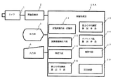
図1には、本発明に係る画像処理装置の構成図が示されている。画像処理装置は影検出装置の機能を内蔵している。画像入力手段或いは画像取得手段として、カメラ1が備えられている。カメラ1により得られた画像信号(例えば、NTSC方式)は画像変換部2に送られ、この画像変換部2においてi×j画素からなるディジタル輝度データに変換され、画像処理部10に取り込まれて処理される。画像処理部10には、表示装置などである出力部3と、キーボードやマウスなどである入力部4とが接続されている。
FIG. 1 is a block diagram of an image processing apparatus according to the present invention. The image processing device incorporates the function of a shadow detection device. A
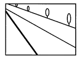
画像処理部10には、背景画像作成・記憶部11が備えられており、例えば、カメラ1より送られて出力部3に表示された複数画像中の所望の画像について入力部4から指示を入力して、背景画像として背景画像作成・記憶部11に記憶される。背景画像作成・記憶部に記憶される背景画像の例としては、例えば道路監視システムでは図2に示されるように車両が含まれない道路の画像である。
The
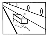
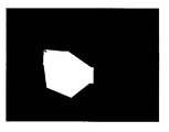
また、画像処理部10には、演算領域検出手段12、特定手段13が備えられている。演算領域検出手段12は、背景画像と入力画像との差分について絶対値を求める演算により差分画像を得て、該差分画像を2値化して白画素領域を演算領域として検出するものである。入力画像が図3に示されるように、車両Cとその影Sを含むものである場合には、差分画像は図4に示されるようになる。そして、この差分画像を2値化することにより得られる2値化画像は図5に示されるようになる。図5の2値化画像において白く現れている領域が演算領域である。
Further, the
特定手段13は、上記演算領域について、入力画像の画素輝度が背景画像の画素輝度と比較して所定値の輝度減衰(対象物による路面の輝度の減衰)が見られる画素を所定値減衰画素として特定するものである。ここで所定値は例えば、60%である。特定手段13は、図5の2値化画像において白く現れている演算領域について、入力画像の画素輝度と背景画像の画素輝度と比較し、入力画像の画素輝度が背景画像の画素輝度の60%となっている画素を取り出し、これらの画素を所定値減衰画素として特定する。特定した所定値減衰画素の領域の輝度を白のものとし、それ以外の領域を黒のものとすると、図6に白領域として現れる影領域が検出される。図5に示した演算領域から上記図6の影領域を除去することにより得られた対象物領域に対してラベリングして処理を行って車両領域を抽出することができる。
The specifying
図1におけるカメラ1以外の画像処理装置は、例えば図7に示されるような構成によるパーソナルコンピュータやワークステーションにより構成される。即ち、図2の計算機は、装置を統括制御するCPU51を有し、このCPU51に上記CPU51が用いるプログラム及びデータ等の情報が記憶される主記憶装置52が接続されている。更に、CPU51には、システムバス53を介してキーボード制御部54、表示制御部55、プリンタ制御部56、入力インタフェース57、マウス制御部58、磁気ディスク制御部59が接続されている。キーボード制御部54には各種情報をキー入力可能なキーボード入力装置60が接続され、表示制御部55には情報を表示するためのCRT表示装置61が接続され、プリンタ制御部56には情報を印字出力するためのプリンタ装置62が接続され、入力インタフェース57には監視カメラ1から画像信号を取り込みA/D変換・多値化を行うための処理部63が接続され、マウス制御部58にはポインティングディバイスであるマウス64が接続され、磁気ディスク制御部59には補助記憶装置である磁気ディスク装置65が接続されている。なお、必要に応じてフレキシブルディスクドライブ、磁気カード或いはICカードリーダ、MO(光磁気ディスク)ドライブ等が設けられる。
The image processing apparatus other than the
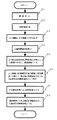
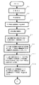
上記の計算機においては、例えば、磁気ディスク装置65に図8に示されるフローチャートに対応する画像処理プログラムが備えられており、これを主記憶装置52へ読み出して実行することにより、図1に示した各手段として画像処理がなされるので、上記フローチャートに基づき動作を説明する。 In the above computer, for example, an image processing program corresponding to the flowchart shown in FIG. 8 is provided in the magnetic disk device 65, and this is read into the main storage device 52 and executed, so that it is shown in FIG. Since image processing is performed as each means, the operation will be described based on the above flowchart.
まず、処理部63から画像信号を取り込み(S1)、背景画像の作成を行う(S2)。この処理は前述の通り、例えば、カメラ1より送られて出力部3であるCRT表示装置61に表示された複数画像中の所望の画像について入力部4であるキーボード入力装置60などから指示を入力して、背景画像として主記憶装置52などに記憶しておく。
First, an image signal is captured from the processing unit 63 (S1), and a background image is created (S2). As described above, this processing is performed, for example, by inputting an instruction from the
次に、現在得られている入力画像を処理部63から画像信号を取り込み、入力画像と先に得ている背景画像とについて、その差分について絶対値を求める演算により差分処理を行う(S3)。この結果、入力画像が図3のようであり背景画像が図2に示すようである場合には、差分画像は図4に示されるようになる。次に、2値化閾値の自動算出を行う(S4)。2値化閾値は、例えば輝度大きく変動している境界に着目して、境界の両側に位置する画素における輝度の平均値などとして得ることが可能である。
Next, an image signal is acquired from the
更に、上記ステップS4において得られた閾値を用いて、図4に示した差分画像について2値化処理を行って2値化画像を作成し、輝度変化が生じた画素を抽出し、この画素により構成される領域を演算領域とする(S5:演算領域検出ステップ)。図5の2値化画像において白く現れている領域が演算領域である。 Further, using the threshold value obtained in step S4, a binarization process is performed on the difference image shown in FIG. 4 to create a binarized image, and a pixel in which a luminance change has occurred is extracted. The configured area is set as a calculation area (S5: calculation area detection step). A region that appears white in the binarized image of FIG. 5 is a calculation region.
次に、演算領域について、入力画像の画素輝度が背景画像の画素輝度と比較して、所定値の輝度減衰が見られる画素を所定値減衰画素として特定する(S6:特定ステップ)。例えば、図5の白く現れている演算領域について、入力画像の画素輝度と背景画像の画素輝度と比較し、入力画像の画素輝度が背景画像の画素輝度の60%となっている画素を取り出し、これらの画素を所定値減衰画素として特定する。 Next, for the calculation area, the pixel luminance of the input image is compared with the pixel luminance of the background image, and a pixel in which luminance attenuation of a predetermined value is seen is specified as the predetermined value attenuation pixel (S6: specifying step). For example, for the calculation area appearing white in FIG. 5, the pixel luminance of the input image is compared with the pixel luminance of the background image, and a pixel in which the pixel luminance of the input image is 60% of the pixel luminance of the background image is extracted. These pixels are specified as predetermined value attenuation pixels.
次に図5の2値化画像において、所定値減衰画素を白としたまま、演算領域における残りの領域を黒画素として影領域を得る(S7)。上記とは逆に図5の2値化画像において、所定値減衰画素を黒とし、演算領域における残りの領域を白画素のままとすることにより白画素領域による対象物(車両)領域を得ることができる(S8)。 Next, in the binarized image of FIG. 5, a shadow area is obtained by setting the remaining area in the calculation area as a black pixel while keeping the predetermined value attenuation pixel white (S7). In contrast to the above, in the binarized image of FIG. 5, the predetermined value attenuation pixel is black, and the remaining area in the calculation area is left as a white pixel, thereby obtaining an object (vehicle) area by the white pixel area. (S8).
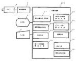
図9に、第2の実施例に係る影検出装置の機能を内蔵している画像処理装置の構成例を示す。この画像処理装置においては図1に示した構成に加えて、第1の平均輝度算出手段14、第2の平均輝度算出手段15、オフセット値算出手段16、演算手段17及び区分手段18を有する画像処理部10Aが備えられている。 FIG. 9 shows a configuration example of an image processing apparatus incorporating the function of the shadow detection apparatus according to the second embodiment. In this image processing apparatus, in addition to the configuration shown in FIG. 1, an image having a first average luminance calculation means 14, a second average luminance calculation means 15, an offset value calculation means 16, a calculation means 17 and a sorting means 18. A processing unit 10A is provided.
この第2の実施例においても、演算領域検出手段12が、背景画像と入力画像との差分について絶対値を求める演算により差分画像を得て、該差分画像を2値化して白画素領域を演算領域として検出し、特定手段13が、上記演算領域について、入力画像の画素輝度が背景画像の画素輝度と比較して所定値の輝度減衰が見られる画素を所定値減衰画素として特定する。第1の平均輝度算出手段14、第2の平均輝度算出手段15、オフセット値算出手段16、演算手段17及び区分手段18による処理は、全て演算領域に対して行われる処理である。
Also in the second embodiment, the calculation area detecting means 12 obtains a difference image by calculating the absolute value of the difference between the background image and the input image, and binarizes the difference image to calculate the white pixel area. The area is detected, and the specifying
ここで、以下の画像処理に用いられる用語を定義しておく。
(i,j):画像中の画素位置を示すインデックス
I(i,j):入力画像
BG(i,j):背景画像
D(i,j):差分画像
Bin(i,j):差分画像を2値化した2値化画像
Coef1:背景画像における輝度の減衰率
Coef2:入力画像と差分画像とから対象物領域を抽出する際における輝度のオフセット値を決定するための係数
Bright1:影と推定された領域における、入力画像中の画素の平均輝度
Bright2:影と推定された領域における、差分画像中の画素の平均輝度
offset:差分画像における演算領域内の画素の輝度を、上記Bright1 に近付けるための輝度の補正値
Dmod (i,j):輝度補正を行った後の差分画像
Binfinal (i,j):入力画像における対象物と推定される領域の画素を主として抽出した最終2値化画像
WP num :差分画像を2値化した2値化画像における白画素の総数
SP num :影領域の画素の総数
Threshold :影除去処理の要否を決定する閾値
Here, terms used in the following image processing are defined.
(i, j): Index indicating the pixel position in the image
I (i, j): Input image
BG (i, j): Background image
D (i, j): Difference image
Bin (i, j): Binary image obtained by binarizing the difference image
Coef1: Decay rate of luminance in the background image
Coef2: Coefficient for determining the luminance offset value when extracting the object area from the input image and the difference image
Bright1: Average brightness of pixels in the input image in the area estimated to be a shadow
Bright2: Average brightness of pixels in the difference image in the area estimated to be a shadow
offset: Brightness correction value to bring the brightness of the pixels in the calculation area of the difference image closer to Bright1
D mod (i, j): Difference image after brightness correction
Bin final (i, j): Final binarized image extracted mainly from pixels of the region estimated to be the target in the input image
WP num: Total number of white pixels in the binarized image obtained by binarizing the difference image
SP num: Total number of pixels in the shadow area
Threshold: Threshold value that determines the necessity of shadow removal processing
以上の通りに定義を行った場合には、特定手段13が行う処理は、演算領域に対して、次の(式1)による条件を満足する画素を特定する処理である。なお、(式1)における Coef1のデフォルト値は例えば0.6である。
I(i,j)<Coef1×BG(i,j)・・・(式1)
When the definition is performed as described above, the process performed by the specifying
I (i, j) <Coef1 × BG (i, j) (Formula 1)
そして、第1の平均輝度算出手段14は、上記(式1)により得られた全画素についての平均輝度Bright1 を求めるものである。第2の平均輝度算出手段15は、背景画像における演算領域について、影と推定された領域における画素の第2の平均輝度Bright2 を求めるものである。第2の平均輝度算出手段15は、求めた第2の平均輝度Bright2 と差分画像における演算領域の画素の輝度比較し、輝度が第2の平均輝度Bright2 よりも大きい画素の輝度を第2の平均輝度Bright2 に置き換えて突出した輝度値を持つ部分を平滑化する。 Then, the first average luminance calculation means 14 obtains the average luminance Bright1 for all the pixels obtained by the above (Equation 1). The second average luminance calculation means 15 obtains the second average luminance Bright2 of the pixels in the area estimated as a shadow for the calculation area in the background image. The second average luminance calculation means 15 compares the obtained second average luminance Bright2 with the luminance of the pixels in the calculation area in the difference image, and determines the luminance of the pixels whose luminance is higher than the second average luminance Bright2 as the second average luminance. Replace the brightness Bright2 and smooth the part with the projected brightness value.
オフセット値算出手段16は、第1の平均輝度Bright1 と第2の平均輝度Bright2 との差に基づき、差分画像における所定値減衰画素についてその輝度を、第1の平均輝度Bright2 に近付けるためのオフセット値offsetを次の(式2)により算出するものである。なお、Coef2は例えば、「2」程度ある。
offset=|(Coef2×(Bright1-Bright2))|・・・・(式2)
Based on the difference between the first average brightness Bright1 and the second average brightness Bright2, the offset value calculation means 16 is an offset value for bringing the brightness of a predetermined value attenuation pixel in the difference image closer to the first average brightness Bright2. The offset is calculated by the following (Expression 2). Coef2 is, for example, about “2”.
offset = | (Coef2 × (Bright1-Bright2)) | ... (Formula 2)
演算手段17は、第1の平均輝度Bright1 と前記第2の平均輝度Bright2 との差及び差分画像における輝度に基づき、差分画像における演算領域の画素についてその輝度を、第1の平均輝度Bright1 に近付けた補正輝度とする演算を行うことにより、以下の(式3)に示す輝度補正を行った後の差分画像 Dmod (i,j)を得る。
Dmod (i,j)= D(i,j)−(Bright2-Bright1)・・・・(式3)
Based on the difference between the first average brightness Bright1 and the second average brightness Bright2 and the brightness in the difference image, the calculation means 17 brings the brightness of the pixels in the calculation area in the difference image closer to the first average brightness Bright1. By performing the calculation to obtain the corrected luminance, the difference image D mod (i, j) after performing the luminance correction shown in the following (Equation 3) is obtained.
D mod (i, j) = D (i, j) − (Bright2-Bright1) (Equation 3)
区分手段18は、入力画像における演算領域の画素について、入力画像における画素輝度 I(i,j)と上記演算手段17により得られた補正輝度 Dmod (i,j)との差の絶対値とオフセット値offsetを比較して、その大小に基づき影領域画素とそれ以外の領域に区分するものである。区分手段18は、次の(式4)を満足する画素を対象物領域に属する画素、それ以外の画素を影領域に属する画素と判定する。
| I(i,j)− Dmod (i,j)|>offset・・・(式4)
The sorting
| I (i, j) −D mod (i, j) |> offset (Expression 4)
そして、画像処理部10Aは、対象物領域に属する画素を白画素へ置き換え、それ以外の画素を黒画素に置き換える2値化処理により得られた最終2値化画像 Binfinal (i,j)(入力画像における対象物と推定される領域の画素を主として抽出した2値化画像)を作成する。この処理で得られた最終2値化画像 Binfinal (i,j)に対してラベリング処理を行い、対象物(車両)領域を抽出する。 Then, the image processing unit 10A replaces the pixels belonging to the object area with white pixels, and replaces the other pixels with black pixels. The final binarized image Bin final (i, j) ( A binarized image in which pixels in a region estimated as an object in the input image are extracted. A labeling process is performed on the final binarized image Bin final (i, j) obtained by this process to extract an object (vehicle) region.
以上の構成に係る画像処理装置は、図7に示す計算機において例えば、磁気ディスク装置65に図10、図11に示されるフローチャートに対応する画像処理プログラムを備えており、これを主記憶装置52へ読み出して実行することにより、図9に示した各手段として画像処理がなされるので、上記フローチャートに基づき動作を説明する。 In the computer shown in FIG. 7, for example, the magnetic disk device 65 includes an image processing program corresponding to the flowcharts shown in FIGS. 10 and 11 in the computer shown in FIG. Since the image processing is performed as each unit shown in FIG. 9 by reading and executing, the operation will be described based on the above flowchart.
ステップS1からステップS6までは、第1の実施例における動作と同じである。次に、演算領域において、(式1)を満足する全画素の平均輝度(第1の平均輝度 Bright1)を求める(S11:第1の平均輝度算出ステップ)。次に、差分画像における演算画像について、影と推定された領域における画素の平均輝度(第2の平均輝度 Bright2)を求める(S12:第2の平均輝度算出ステップ)。 Steps S1 to S6 are the same as those in the first embodiment. Next, an average luminance (first average luminance Bright1) of all pixels satisfying (Expression 1) is obtained in the calculation area (S11: first average luminance calculation step). Next, an average luminance (second average luminance Bright2) of pixels in an area estimated as a shadow is calculated for the calculated image in the difference image (S12: second average luminance calculation step).
上記ステップS12の次に、差分画像の演算領域において第2の平均輝度 Bright2よりも大きい輝度の画素における輝度を第2の平均輝度 Bright2へ置き換える平滑化を行う(S13)。更に、オフセットoffsetを(式2)から求める(S14:オフセット値算出ステップ)。次に、(式3)に基づき輝度補正した差分画像 Dmod (i,j)を求める(S15:演算ステップ)。この輝度補正により元の差分画像(演算領域内)が影と推定された領域における、入力画像中の画素の平均輝度に近付けられる。 Following step S12, smoothing is performed to replace the luminance in the pixels having a luminance higher than the second average luminance Bright2 with the second average luminance Bright2 in the calculation area of the difference image (S13). Further, an offset offset is obtained from (Expression 2) (S14: offset value calculation step). Next, a difference image D mod (i, j) corrected for luminance based on (Equation 3) is obtained (S15: calculation step). By this luminance correction, the original difference image (in the calculation region) is brought close to the average luminance of the pixels in the input image in the region estimated as a shadow.
次に、(式4)を満足する画素を対象物領域に属する画素とする(S16:区分ステップ)。この(式4)は、元の差分画像(演算領域内)が影と推定された領域における、入力画像中の画素の平均輝度に近付けられた輝度補正に係る差分画像と入力画像中の画素の差が、オフセット値offset(差分画像における演算領域内の画素の輝度を、上記Bright1 に近付けるための輝度の補正値)を、超えているかを検出するものである。極端に言えば、図4に示される差分画像の領域S1(影領域)の輝度を、図3に示す入力画像の影の輝度に入れ替えることにより、輝度補正された差分画像の演算領域では、影領域が図3に示す入力画像おける値を有し、対象物領域が図4の差分画像における値を有するから、式4の絶対値内の値は、影領域でオフセット値offset(図3の影領域の輝度と図4の影領域の差)と等しいかそれ以下となるのに対し、対象物領域ではオフセット値offsetより遥かに大きな値を採ることが予測される。この原理を用いて対象物領域の検出を行っている。
Next, a pixel satisfying (Expression 4) is set as a pixel belonging to the object region (S16: classification step). This (Equation 4) is the difference between the difference image related to the luminance correction brought close to the average luminance of the pixels in the input image and the pixels in the input image in the region where the original difference image (in the calculation region) is estimated as a shadow. It is detected whether the difference exceeds the offset value offset (the brightness correction value for bringing the brightness of the pixels in the calculation area in the difference image closer to Bright1). Extremely speaking, by replacing the luminance of the region S1 (shadow region) of the difference image shown in FIG. 4 with the luminance of the shadow of the input image shown in FIG. Since the area has a value in the input image shown in FIG. 3 and the object area has a value in the difference image in FIG. 4, the value in the absolute value of
上記ステップS16の次に、対象物領域に属する画素を白画素へ置き換え、残りの画素を黒画素に置き換える2値化を行って(S17)、更に上記2値化により得られた最終2値化画像 Binfinal (i,j)にラベリングを行って、対象物(車両)領域の抽出を行う(S18)。斯して、より精度の高い対象物(車両)領域の抽出を行うことができる。 Subsequent to step S16, binarization is performed by replacing pixels belonging to the object area with white pixels and the remaining pixels with black pixels (S17), and final binarization obtained by the above binarization. The image Bin final (i, j) is labeled to extract an object (vehicle) region (S18). Thus, it is possible to extract a target (vehicle) region with higher accuracy.
図12に、影除去判定機能を内蔵している第3の実施例に係る画像処理装置の構成例を示す。この画像処理装置においては図9に示した構成に加えて、影除去判定手段19を有する画像処理部10Bが備えられている。この影除去判定手段19は、影領域の画素数と影領域以外の領域の画素数の比と、所定閾値を比較して前記影領域とされた領域を対象物領域から除去するか否か判定するものである。
FIG. 12 shows a configuration example of an image processing apparatus according to the third embodiment incorporating a shadow removal determination function. In addition to the configuration shown in FIG. 9, the image processing apparatus includes an
具体的には、図5に示した差分画像についての2値化画像中の白画素の総数WP num と、区分手段18により得られた影領域の画素の総数SP num を用いて、次の条件が満たされているか否かに基づき影の発生の有無を検出する。
(SP num /WP num )>Threshold (デフォルトで0.2)・・・・(式5)
Specifically, the total number WP num of white pixels in the binarized image with respect to the difference image shown in FIG. 5 and the total number SP of pixels in the shadow area obtained by the sorting
(SP num / WP num)> Threshold (0.2 by default) ... (Formula 5)
上記の(式5)が満足されると、影領域有りとして、第2の実施例により示された処理により影領域と対象物領域の抽出を行う。一方、(式5)が満足されない場合には、影領域無しとして、図4に示した背景差分画像について2値化を行った結果である図5の2値化画像の白領域を対象物領域として抽出する。 If the above (Formula 5) is satisfied, the shadow area and the object area are extracted by the process shown in the second embodiment, assuming that there is a shadow area. On the other hand, if (Equation 5) is not satisfied, the white area of the binarized image of FIG. 5 which is the result of binarization of the background difference image shown in FIG. Extract as
上記の画像処理装置は、図7に示す計算機において例えば、磁気ディスク装置65に図10、図11、図13に示されるフローチャートに対応する画像処理プログラムを備えており、これを主記憶装置52へ読み出して実行することにより、図12に示した各手段として画像処理がなされるので、上記フローチャートに基づき動作を説明する。 In the computer shown in FIG. 7, for example, the above-described image processing apparatus has an image processing program corresponding to the flowcharts shown in FIGS. 10, 11, and 13 in the magnetic disk device 65. Since the image processing is performed as each unit shown in FIG. 12 by reading and executing, the operation will be described based on the above flowchart.
図10、図11のフローチャートにおけるステップS1からステップS16までの処理は変わらない。ステップS16に次いで図13に示されるフローチャートによる処理へ進む。そして、図5に示した差分画像についての2値化画像中の白画素の総数WP num と、区分手段18により得られた影領域の画素の総数SP num を用いて、(式5)の条件が満たされているか否かに基づき影の発生の有無を検出する(S21、S22:影除去判定ステップ)。 The processing from step S1 to step S16 in the flowcharts of FIGS. 10 and 11 is not changed. Following step S16, the process proceeds to the process shown in the flowchart of FIG. The total number WP of white pixels in the binarized image for the difference image shown in FIG. num and the total number SP of shadow region pixels obtained by the sorting means 18 Using num, the presence or absence of a shadow is detected based on whether or not the condition of (Expression 5) is satisfied (S21, S22: shadow removal determination step).
上記ステップS22において、(式5)が満足されていることが検出されると、影領域有りとして第2の実施例におけるステップS17、S18に示された処理により影領域と対象物領域の抽出を行う。一方、(式5)が満足されない場合には、影領域無しとして、図4に示した背景差分画像について2値化を行った結果である図5の2値化画像の白領域を対象物領域として抽出する(S23)。 If it is detected in the above step S22 that (Equation 5) is satisfied, the shadow area and the object area are extracted by the processing shown in steps S17 and S18 in the second embodiment, assuming that there is a shadow area. Do. On the other hand, if (Equation 5) is not satisfied, the white area of the binarized image of FIG. 5 which is the result of binarization of the background difference image shown in FIG. (S23).
この実施例により、影を除去する必要の有無が判定され、必要な場合に影除去がされた対象物領域の検出がなされる。 According to this embodiment, it is determined whether or not it is necessary to remove the shadow, and the object area from which the shadow is removed is detected when necessary.
道路上の車両領域の検出のみならず、侵入監視などの各種監視を行う場合に、影除去を行って適切な対象物領域の検出へ応用することができる。 When performing various types of monitoring such as intrusion monitoring as well as detection of a vehicle region on a road, shadow removal can be performed and applied to detection of an appropriate target region.
1 カメラ
2 画像変換部
3 出力部
4 入力部
10、10A、10B 画像処理部
11 背景画像作成・記憶部
12 演算領域検出手段
13 特定手段
14 第1の平均輝度算出手段
15 第2の平均輝度算出手段
16 オフセット値算出手段
17 演算手段
18 区分手段
19 影除去判定手段
DESCRIPTION OF
Claims (15)
前記演算領域について、入力画像の画素輝度が背景画像の画素輝度と比較して所定値の輝度減衰が見られる画素を所定値減衰画素として特定する特定手段と
を具備し、
前記所定値減衰画素の領域を影として検出することを特徴とする影検出装置。 A calculation area detecting means for obtaining a difference image by calculating an absolute value for a difference between the background image and the input image, binarizing the difference image, and detecting a white pixel area as a calculation area;
A specifying means for specifying, as the predetermined value attenuation pixel, a pixel in which the pixel luminance of the input image has a luminance attenuation of a predetermined value compared to the pixel luminance of the background image with respect to the calculation region;
A shadow detection apparatus that detects a region of the predetermined value attenuation pixel as a shadow.
前記演算領域について、入力画像の画素輝度が背景画像の画素輝度と比較して所定値の輝度減衰が見られる画素を所定値減衰画素として特定する特定手段と、
前記所定値減衰画素について、入力画像において画素輝度の平均輝度である第1の平均輝度を算出する第1の平均輝度算出手段と、
前記所定値減衰画素について、差分画像において画素輝度の平均輝度である第2の平均輝度を算出する第2の平均輝度算出手段と、
前記第1の平均輝度と前記第2の平均輝度との差に基づき、差分画像における前記所定値減衰画素についてその輝度を、前記第1の平均輝度に近付けるためのオフセット値を算出するオフセット値算出手段と、
前記第1の平均輝度と前記第2の平均輝度との差及び前記差分画像における輝度に基づき、前記差分画像における前記演算領域の画素についてその輝度を、前記第1の平均輝度に近付けた補正輝度とする演算を行う演算手段と、
入力画像における前記演算領域の画素について、入力画像における画素輝度と前記差分画像における前記補正輝度との差の絶対値と前記オフセット値を比較して、その大小に基づき影領域画素とそれ以外の領域に区分する区分手段と
を具備し、
前記影領域画素の領域を影として検出することを特徴とする影検出装置。 A calculation area detecting means for obtaining a difference image by calculating an absolute value for a difference between the background image and the input image, binarizing the difference image, and detecting a white pixel area as a calculation area;
For the calculation area, a specifying unit that specifies, as a predetermined value attenuation pixel, a pixel in which the pixel luminance of the input image is compared with the pixel luminance of the background image and a predetermined value of luminance attenuation is seen
A first average luminance calculating means for calculating a first average luminance that is an average luminance of the pixel luminance in the input image for the predetermined value attenuation pixel;
A second average luminance calculating means for calculating a second average luminance that is an average luminance of the pixel luminance in the difference image for the predetermined value attenuation pixel;
Based on the difference between the first average luminance and the second average luminance, offset value calculation for calculating an offset value for bringing the luminance of the predetermined value attenuation pixel in the difference image closer to the first average luminance. Means,
Based on the difference between the first average luminance and the second average luminance and the luminance in the difference image, the corrected luminance in which the luminance of the pixels in the calculation area in the difference image is close to the first average luminance An arithmetic means for performing an arithmetic operation,
For the pixels in the calculation region in the input image, the absolute value of the difference between the pixel luminance in the input image and the corrected luminance in the difference image is compared with the offset value, and the shadow region pixel and the other region are based on the magnitude And classifying means for classifying
A shadow detection apparatus that detects a region of the shadow region pixel as a shadow.
前記演算領域から前記所定値減衰画素の領域を除いた領域を対象物領域として画像処理を行うことを特徴とする画像処理装置。 The shadow detection apparatus according to claim 1,
An image processing apparatus that performs image processing using an area obtained by excluding the area of the predetermined value attenuation pixel from the calculation area as an object area.
前記区分手段により影領域画素以外の領域とされた領域を対象物領域として画像処理を行うことを特徴とする画像処理装置。 A shadow detection apparatus according to claim 2,
An image processing apparatus that performs image processing using an area defined as an area other than a shadow area pixel by the classification unit as an object area.
前記演算領域について、入力画像の画素輝度が背景画像の画素輝度と比較して所定値の輝度減衰が見られる画素を所定値減衰画素として特定する特定ステップと
を具備し、
前記所定値減衰画素の領域を影として検出することを特徴とする影検出方法。 A calculation area detection step of obtaining a difference image by calculating an absolute value for a difference between the background image and the input image, binarizing the difference image, and detecting a white pixel area as a calculation area;
A step of specifying, as the predetermined value attenuation pixel, a pixel in which the pixel luminance of the input image has a luminance attenuation of a predetermined value compared to the pixel luminance of the background image with respect to the calculation region;
A shadow detection method, wherein the predetermined value attenuation pixel region is detected as a shadow.
前記演算領域について、入力画像の画素輝度が背景画像の画素輝度と比較して所定値の輝度減衰が見られる画素を所定値減衰画素として特定する特定ステップと、
前記所定値減衰画素について、入力画像において画素輝度の平均輝度である第1の平均輝度を算出する第1の平均輝度算出ステップと、
前記所定値減衰画素について、差分画像において画素輝度の平均輝度である第2の平均輝度を算出する第2の平均輝度算出ステップと、
前記第1の平均輝度と前記第2の平均輝度との差に基づき、差分画像における前記所定値減衰画素についてその輝度を、前記第1の平均輝度に近付けるためのオフセット値を算出するオフセット値算出ステップと、
前記第1の平均輝度と前記第2の平均輝度との差及び前記差分画像における輝度に基づき、差分画像における前記演算領域の画素についてその輝度を、前記第1の平均輝度に近付けた補正輝度とする演算を行う演算ステップと、
入力画像における前記演算領域の画素について、入力画像における画素輝度差分と画像における前記補正輝度との差の絶対値と前記オフセット値を比較して、その大小に基づき影領域画素とそれ以外の領域に区分する区分ステップと
を具備し、
前記影領域画素の領域を影として検出することを特徴とする影検出方法。 A calculation area detection step of obtaining a difference image by calculating an absolute value for a difference between the background image and the input image, binarizing the difference image, and detecting a white pixel area as a calculation area;
A specific step of specifying, as the predetermined value attenuation pixel, a pixel in which the pixel luminance of the input image is compared with the pixel luminance of the background image and a predetermined value of luminance attenuation is seen for the calculation region;
A first average luminance calculating step for calculating a first average luminance which is an average luminance of the pixel luminance in the input image for the predetermined value attenuation pixel;
A second average luminance calculating step of calculating a second average luminance that is an average luminance of the pixel luminance in the difference image for the predetermined value attenuation pixel;
Based on the difference between the first average luminance and the second average luminance, offset value calculation for calculating an offset value for bringing the luminance of the predetermined value attenuation pixel in the difference image closer to the first average luminance. Steps,
Based on the difference between the first average luminance and the second average luminance and the luminance in the difference image, the luminance of the pixel in the calculation area in the difference image is adjusted to be close to the first average luminance. An operation step for performing an operation to be performed;
For the pixels in the calculation area in the input image, the absolute value of the difference between the pixel luminance difference in the input image and the corrected luminance in the image is compared with the offset value, and the shadow area pixel and the other area are compared based on the magnitude. A classification step for classifying, and
A shadow detection method for detecting a region of the shadow region pixel as a shadow.
前記演算領域から前記所定値減衰画素の領域を除いた領域を対象物領域として画像処理を行うことを特徴とする画像処理方法。 Using the shadow detection method according to claim 6,
An image processing method, wherein image processing is performed using an area obtained by excluding the area of the predetermined value attenuation pixel from the calculation area as an object area.
前記区分ステップにより影領域画素以外の領域とされた領域を対象物領域として画像処理を行うことを特徴とする画像処理方法。 Using the shadow detection method according to claim 7,
An image processing method characterized in that image processing is performed using an area defined as an area other than a shadow area pixel by the classification step as an object area.
背景画像と入力画像との差分について絶対値を求める演算により差分画像を得て、該差分画像を2値化して白画素領域を演算領域として検出する演算領域検出ステップと、
前記演算領域について、入力画像の画素輝度が背景画像の画素輝度と比較して所定値の輝度減衰が見られる画素を所定値減衰画素として特定する特定ステップと
を具備し、
前記所定値減衰画素の領域を影として検出することを特徴とする影検出プログラム。 A program executed on a computer,
A calculation area detection step of obtaining a difference image by calculating an absolute value for a difference between the background image and the input image, binarizing the difference image, and detecting a white pixel area as a calculation area;
A step of specifying, as the predetermined value attenuation pixel, a pixel in which the pixel luminance of the input image has a luminance attenuation of a predetermined value compared to the pixel luminance of the background image with respect to the calculation region;
A shadow detection program for detecting a region of the predetermined value attenuation pixel as a shadow.
背景画像と入力画像との差分について絶対値を求める演算により差分画像を得て、該差分画像を2値化して白画素領域を演算領域として検出する演算領域検出ステップと、
前記演算領域について、入力画像の画素輝度が背景画像の画素輝度と比較して所定値の輝度減衰が見られる画素を所定値減衰画素として特定する特定ステップと、
前記所定値減衰画素について、入力画像において画素輝度の平均輝度である第1の平均輝度を算出する第1の平均輝度算出ステップと、
前記所定値減衰画素について、差分画像において画素輝度の平均輝度である第2の平均輝度を算出する第2の平均輝度算出ステップと、
前記第1の平均輝度と前記第2の平均輝度との差に基づき、差分画像における前記所定値減衰画素についてその輝度を、前記第1の平均輝度に近付けるためのオフセット値を算出するオフセット値算出ステップと、
前記第1の平均輝度と前記第2の平均輝度との差及び前記差分画像における輝度に基づき、差分画像における前記演算領域の画素についてその輝度を、前記第1の平均輝度に近付けた補正輝度とする演算を行う演算ステップと、
入力画像における前記演算領域の画素について、入力画像における画素輝度と差分画像における前記補正輝度との差の絶対値と前記オフセット値を比較して、その大小に基づき影領域画素とそれ以外の領域に区分する区分ステップと
を具備し、
前記影領域画素の領域を影として検出することを特徴とする影検出プログラム。 A program executed on a computer,
A calculation area detection step of obtaining a difference image by calculating an absolute value for a difference between the background image and the input image, binarizing the difference image, and detecting a white pixel area as a calculation area;
A specific step of specifying, as the predetermined value attenuation pixel, a pixel in which the pixel luminance of the input image is compared with the pixel luminance of the background image and a predetermined value of luminance attenuation is seen for the calculation region;
A first average luminance calculating step for calculating a first average luminance which is an average luminance of the pixel luminance in the input image for the predetermined value attenuation pixel;
A second average luminance calculating step of calculating a second average luminance that is an average luminance of the pixel luminance in the difference image for the predetermined value attenuation pixel;
Based on the difference between the first average luminance and the second average luminance, offset value calculation for calculating an offset value for bringing the luminance of the predetermined value attenuation pixel in the difference image closer to the first average luminance. Steps,
Based on the difference between the first average luminance and the second average luminance and the luminance in the difference image, the luminance of the pixel in the calculation area in the difference image is adjusted to be close to the first average luminance. An operation step for performing an operation to be performed;
For the pixels in the calculation area in the input image, the absolute value of the difference between the pixel brightness in the input image and the corrected brightness in the difference image is compared with the offset value, and the shadow area pixel and other areas are compared based on the magnitude. A classification step for classifying, and
A shadow detection program for detecting an area of the shadow area pixel as a shadow.
前記演算領域から前記所定値減衰画素の領域を除いた領域を対象物領域として画像処理を行うことを特徴とする画像処理プログラム。 A shadow detection program according to claim 11,
An image processing program for performing image processing using an area obtained by excluding the area of the predetermined value attenuation pixel from the calculation area as an object area.
前記区分ステップにより影領域画素以外の領域とされた領域を対象物領域として画像処理を行うことを特徴とする画像処理プログラム。 A shadow detection program according to claim 12,
An image processing program for performing image processing using an area determined as an area other than a shadow area pixel by the classification step as an object area.
Priority Applications (1)
| Application Number | Priority Date | Filing Date | Title |
|---|---|---|---|
| JP2004064843A JP4253265B2 (en) | 2004-03-08 | 2004-03-08 | Shadow detection apparatus, shadow detection method and shadow detection program, image processing apparatus using shadow detection apparatus, image processing method using shadow detection method, and image processing program using shadow detection program |
Applications Claiming Priority (1)
| Application Number | Priority Date | Filing Date | Title |
|---|---|---|---|
| JP2004064843A JP4253265B2 (en) | 2004-03-08 | 2004-03-08 | Shadow detection apparatus, shadow detection method and shadow detection program, image processing apparatus using shadow detection apparatus, image processing method using shadow detection method, and image processing program using shadow detection program |
Publications (3)
| Publication Number | Publication Date |
|---|---|
| JP2005251132A JP2005251132A (en) | 2005-09-15 |
| JP2005251132A5 JP2005251132A5 (en) | 2006-03-23 |
| JP4253265B2 true JP4253265B2 (en) | 2009-04-08 |
Family
ID=35031521
Family Applications (1)
| Application Number | Title | Priority Date | Filing Date |
|---|---|---|---|
| JP2004064843A Expired - Fee Related JP4253265B2 (en) | 2004-03-08 | 2004-03-08 | Shadow detection apparatus, shadow detection method and shadow detection program, image processing apparatus using shadow detection apparatus, image processing method using shadow detection method, and image processing program using shadow detection program |
Country Status (1)
| Country | Link |
|---|---|
| JP (1) | JP4253265B2 (en) |
Families Citing this family (4)
| Publication number | Priority date | Publication date | Assignee | Title |
|---|---|---|---|---|
| DE102007029476A1 (en) | 2007-06-26 | 2009-01-08 | Robert Bosch Gmbh | Image processing apparatus for shadow detection and suppression, method and computer program |
| US8755634B2 (en) | 2009-08-12 | 2014-06-17 | Nec Corporation | Obstacle detection device and method and obstacle detection system |
| KR102356448B1 (en) * | 2014-05-05 | 2022-01-27 | 삼성전자주식회사 | Method for composing image and electronic device thereof |
| CN112686122B (en) * | 2020-12-25 | 2023-09-29 | 浙江大华技术股份有限公司 | Human body and shadow detection method and device, electronic equipment and storage medium |
-
2004
- 2004-03-08 JP JP2004064843A patent/JP4253265B2/en not_active Expired - Fee Related
Also Published As
| Publication number | Publication date |
|---|---|
| JP2005251132A (en) | 2005-09-15 |
Similar Documents
| Publication | Publication Date | Title |
|---|---|---|
| EP3176751B1 (en) | Information processing device, information processing method, computer-readable recording medium, and inspection system | |
| JP4626886B2 (en) | Method and apparatus for locating and extracting captions in digital images | |
| US9965695B1 (en) | Document image binarization method based on content type separation | |
| JP4877374B2 (en) | Image processing apparatus and program | |
| CN105469027A (en) | Horizontal and vertical line detection and removal for document images | |
| JP2010525486A (en) | Image segmentation and image enhancement | |
| JP2008148298A (en) | Method and apparatus for identifying regions of different content in image, and computer readable medium for embodying computer program for identifying regions of different content in image | |
| US20060245650A1 (en) | Precise grayscale character segmentation apparatus and method | |
| JP2008286725A (en) | Person detector and detection method | |
| JP4821663B2 (en) | Character noise elimination device, character noise elimination method, character noise elimination program | |
| KR20130072073A (en) | Apparatus and method for extracting edge in image | |
| JP6432296B2 (en) | Device and method for detecting zebra crossings in images | |
| JP2011165170A (en) | Object detection device and program | |
| JP4253265B2 (en) | Shadow detection apparatus, shadow detection method and shadow detection program, image processing apparatus using shadow detection apparatus, image processing method using shadow detection method, and image processing program using shadow detection program | |
| US7646892B2 (en) | Image inspecting apparatus, image inspecting method, control program and computer-readable storage medium | |
| JP2010186246A (en) | Image processing apparatus, method, and program | |
| KR20150099116A (en) | Method for recognizing a color character using optical character recognition and apparatus thereof | |
| JP6643301B2 (en) | Defect inspection device and defect inspection method | |
| CN107330470B (en) | Method and device for identifying picture | |
| US6983071B2 (en) | Character segmentation device, character segmentation method used thereby, and program therefor | |
| JP4230960B2 (en) | Image processing apparatus, image processing method, and image processing program | |
| CN112801963A (en) | Video image occlusion detection method and system | |
| JP4230962B2 (en) | Image processing apparatus, image processing method, and image processing program | |
| CN114596210A (en) | Noise estimation method, device, terminal equipment and computer readable storage medium | |
| JP2011203853A (en) | Image processing apparatus and program |
Legal Events
| Date | Code | Title | Description |
|---|---|---|---|
| A521 | Written amendment |
Free format text: JAPANESE INTERMEDIATE CODE: A523 Effective date: 20060201 |
|
| A621 | Written request for application examination |
Free format text: JAPANESE INTERMEDIATE CODE: A621 Effective date: 20060201 |
|
| A131 | Notification of reasons for refusal |
Free format text: JAPANESE INTERMEDIATE CODE: A131 Effective date: 20080909 |
|
| TRDD | Decision of grant or rejection written | ||
| A01 | Written decision to grant a patent or to grant a registration (utility model) |
Free format text: JAPANESE INTERMEDIATE CODE: A01 Effective date: 20090120 |
|
| A01 | Written decision to grant a patent or to grant a registration (utility model) |
Free format text: JAPANESE INTERMEDIATE CODE: A01 |
|
| A61 | First payment of annual fees (during grant procedure) |
Free format text: JAPANESE INTERMEDIATE CODE: A61 Effective date: 20090123 |
|
| FPAY | Renewal fee payment (event date is renewal date of database) |
Free format text: PAYMENT UNTIL: 20120130 Year of fee payment: 3 |
|
| FPAY | Renewal fee payment (event date is renewal date of database) |
Free format text: PAYMENT UNTIL: 20130130 Year of fee payment: 4 |
|
| FPAY | Renewal fee payment (event date is renewal date of database) |
Free format text: PAYMENT UNTIL: 20130130 Year of fee payment: 4 |
|
| FPAY | Renewal fee payment (event date is renewal date of database) |
Free format text: PAYMENT UNTIL: 20140130 Year of fee payment: 5 |
|
| LAPS | Cancellation because of no payment of annual fees |