JP4253178B2 - Method for manufacturing analytical tool - Google Patents
Method for manufacturing analytical tool Download PDFInfo
- Publication number
- JP4253178B2 JP4253178B2 JP2002350197A JP2002350197A JP4253178B2 JP 4253178 B2 JP4253178 B2 JP 4253178B2 JP 2002350197 A JP2002350197 A JP 2002350197A JP 2002350197 A JP2002350197 A JP 2002350197A JP 4253178 B2 JP4253178 B2 JP 4253178B2
- Authority
- JP
- Japan
- Prior art keywords
- reagent
- material liquid
- analytical tool
- tool according
- producing
- Prior art date
- Legal status (The legal status is an assumption and is not a legal conclusion. Google has not performed a legal analysis and makes no representation as to the accuracy of the status listed.)
- Expired - Lifetime
Links
Images


Classifications
-
- A—HUMAN NECESSITIES
- A21—BAKING; EDIBLE DOUGHS
- A21C—MACHINES OR EQUIPMENT FOR MAKING OR PROCESSING DOUGHS; HANDLING BAKED ARTICLES MADE FROM DOUGH
- A21C11/00—Other machines for forming the dough into its final shape before cooking or baking
- A21C11/16—Extruding machines
- A21C11/163—Applying co-extrusion, i.e. extruding two or more plastic substances simultaneously, e.g. for making filled dough products; Making products from two or more different substances supplied to the extruder
-
- B—PERFORMING OPERATIONS; TRANSPORTING
- B01—PHYSICAL OR CHEMICAL PROCESSES OR APPARATUS IN GENERAL
- B01L—CHEMICAL OR PHYSICAL LABORATORY APPARATUS FOR GENERAL USE
- B01L3/00—Containers or dishes for laboratory use, e.g. laboratory glassware; Droppers
- B01L3/50—Containers for the purpose of retaining a material to be analysed, e.g. test tubes
- B01L3/508—Containers for the purpose of retaining a material to be analysed, e.g. test tubes rigid containers not provided for above
- B01L3/5085—Containers for the purpose of retaining a material to be analysed, e.g. test tubes rigid containers not provided for above for multiple samples, e.g. microtitration plates
-
- B—PERFORMING OPERATIONS; TRANSPORTING
- B01—PHYSICAL OR CHEMICAL PROCESSES OR APPARATUS IN GENERAL
- B01L—CHEMICAL OR PHYSICAL LABORATORY APPARATUS FOR GENERAL USE
- B01L2200/00—Solutions for specific problems relating to chemical or physical laboratory apparatus
- B01L2200/12—Specific details about manufacturing devices
-
- B—PERFORMING OPERATIONS; TRANSPORTING
- B01—PHYSICAL OR CHEMICAL PROCESSES OR APPARATUS IN GENERAL
- B01L—CHEMICAL OR PHYSICAL LABORATORY APPARATUS FOR GENERAL USE
- B01L2200/00—Solutions for specific problems relating to chemical or physical laboratory apparatus
- B01L2200/16—Reagents, handling or storing thereof
-
- B—PERFORMING OPERATIONS; TRANSPORTING
- B01—PHYSICAL OR CHEMICAL PROCESSES OR APPARATUS IN GENERAL
- B01L—CHEMICAL OR PHYSICAL LABORATORY APPARATUS FOR GENERAL USE
- B01L2300/00—Additional constructional details
- B01L2300/08—Geometry, shape and general structure
- B01L2300/0809—Geometry, shape and general structure rectangular shaped
- B01L2300/0816—Cards, e.g. flat sample carriers usually with flow in two horizontal directions
-
- B—PERFORMING OPERATIONS; TRANSPORTING
- B01—PHYSICAL OR CHEMICAL PROCESSES OR APPARATUS IN GENERAL
- B01L—CHEMICAL OR PHYSICAL LABORATORY APPARATUS FOR GENERAL USE
- B01L2400/00—Moving or stopping fluids
- B01L2400/04—Moving fluids with specific forces or mechanical means
- B01L2400/0403—Moving fluids with specific forces or mechanical means specific forces
- B01L2400/0406—Moving fluids with specific forces or mechanical means specific forces capillary forces
Landscapes
- Health & Medical Sciences (AREA)
- Chemical & Material Sciences (AREA)
- General Health & Medical Sciences (AREA)
- Food Science & Technology (AREA)
- Engineering & Computer Science (AREA)
- Analytical Chemistry (AREA)
- Life Sciences & Earth Sciences (AREA)
- Hematology (AREA)
- Clinical Laboratory Science (AREA)
- Chemical Kinetics & Catalysis (AREA)
- Investigating Or Analysing Biological Materials (AREA)
- Investigating Or Analyzing Non-Biological Materials By The Use Of Chemical Means (AREA)
- Sampling And Sample Adjustment (AREA)
- Investigating Or Analysing Materials By The Use Of Chemical Reactions (AREA)
- Analysing Materials By The Use Of Radiation (AREA)
Abstract
Description
【0001】
【発明の属する技術分野】
本発明は、試料液中の特定成分を分析するために利用され、かつ上記特定成分を反応させるための試薬を含んだ試薬部を備えた分析用具を製造する方法に関する。
【0002】
【従来の技術】
試料の分析方法としては、たとえば試料と試薬を反応させたときの反応液を、光学的手法により分析する方法がある。このような手法により試料の分析を行う場合には、反応場を提供する分析用具が利用されている。そして、微量な試料を分析する場合、分析用具としては、微細な流路が形成された、いわゆるマイクロデバイスが利用されている。一方、分析用具における試料と試薬との反応は、たとえば分析用具に設定された反応部に対して試薬部を予め形成しておき、この試薬部に試料を供給することにより行われる。
【0003】
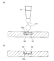
分析用具の試薬部は、たとえば反応部に対して試薬を含む材料液を供給した後に、材料液を乾燥させることにより形成される。反応部に対する材料液の供給は、典型的には、図11(a)に示したようにディスペンサ91を用いて行われる。反応部90に対する材料液92の供給は、インクジェット方式を利用した吐出装置を用いて行うこともできる(たとえば特許文献1参照)。
【0004】
上述した試薬部の形成方法では、反応部90に保持された材料液92を乾燥させるときに、反応部90の中央部に位置する材料液92においては液成分が積極的に蒸発して固体成分の濃度が大きくなる。その一方で、マイクロデバイスのように、反応部90を含めた流路全体が微細化された構成では、材料液92における反応部90の側面90aと接触する部分については、材料液92を乾燥させるときに、材料液92の表面張力(毛細管力)によって材料液92が側面90aに接触した状態が維持される。つまり、材料液92を乾燥させる過程においては、材料液の周縁部に比べて、材料液92の中央部のほうが蒸発速度が大きくなる。その結果、図11(b)に示したように、最終的に形成される試薬部93は、中央部の厚みが小さく、周縁部が側面90aに密着して厚みが大きくなる。したがって、マイクロデバイスのような分析用具では、ディスペンサ91を用いて試薬部93を形成する方法を採用した場合には、試薬部93の厚みに不均一さが生じ、さらには試薬部93を溶解させたときに、反応部90において試薬の濃度にバラツキが生じ得る。
【0005】
このような不具合を解消するためには、図12に示したように、反応部90に保持された材料液92の表面を圧力棒94により押さえつつ、材料液92を乾燥させて試薬部を形成することが考えられる(たとえば特許文献2参照)。
【0006】
【特許文献1】
特開2000−229245号公報
【特許文献2】
特開平9−101297号公報
【0007】
【発明が解決しようとする課題】
材料液92の表面を圧力棒94により押さえながら材料液92を乾燥させれば、圧力棒94と接触する部分については試薬部の厚みを一定化し、試薬の濃度のバラツキを抑制することができる。しかしながら、図12に良く表れているように、たとえば反応部90の中央部に位置する材料液92の表面のみを押さえ付けた場合には、反応部90の周縁部に位置する部分については、圧力棒94を用いない場合と同様に、中央部に比べて試薬部の厚みが大きくなる。
【0008】
このような厚みムラを最小限に抑えるためには、圧力棒94における押圧部分94aのサイズを、反応部90のサイズにより近づける必要がある。ところが、先にも触れたように、マイクロデバイスでは、反応部90のサイズが小さいため、押圧部分94aのサイズを反応部90のサイズに近づけるためには、厳しい寸法公差が要求され、圧力棒94の製造が困難で、製造コスト的にも不利となる。また、マイクロデバイスの試薬部は、厚み寸法が10μm以下の薄層に形成されることがあるが、このような試薬部において厚みムラを抑制するためには、材料液92の表面を押圧する際に、反応部90の底面90bと押圧部分94aの表面との間で、高いレベルの平行性を維持する必要がある。そのためには、圧力棒94に対して高い加工精度が要求され、また圧力棒94により材料液92を押さえる際に、圧力棒94に対してシビアな位置精度が要求される。したがって、圧力棒94により材料液92の表面を押さえつつ試薬部を形成する方法では、圧力棒94の加工面および操作面において不利である。
【0009】
本発明は、このような事情のもとに考えだされたものであって、試薬部を備えた分析用具を製造する場合において、サイズの小さい試薬部であっても、コスト的に有利に、厚みムラを小さくできるようにすることを課題としている。
【0010】
【発明の開示】
本発明では、上記した課題を解決すべく、次の技術的手段を講じている。すなわち、本発明により提供される分析用具の製造方法は、基板上に形成された、底面および側面を有するとともに上記基板の厚み方向に凹んだ試薬部保持部に、上記底面に密着するようにして、試料液中の特定成分と反応させるための試薬を含んだ試薬部を形成するための試薬部形成工程を有する分析用具の製造方法であって、上記試薬部形成工程は、上記試薬を含む材料液を、上記底面における上記側面から一定距離隔てた領域に対して塗布した後に上記材料液を乾燥させる複数回の塗布・乾燥作業を含んでいる一方、上記試薬部形成工程は、一つの試薬保持部に、複数種類の試薬が、相互に接触して全て露出するようにして行うことを特徴としている。
【0011】
複数回の塗布・乾燥作業は、たとえば同一の試薬を含む材料液を用いて、2〜200回行われる。材料液としては、たとえば試薬を0.1〜60wt%含むものが使用される。
【0012】
本発明の製造対象となる分析用具は、たとえば基板に形成された試薬保持部に対して試薬部が形成されたものである。この場合、試薬保持部の側面における基板の厚み方向の寸法は、たとえば50〜200μmとされる。試薬保持部の側面と、材料液を塗布する領域との距離は、たとえば0.1μm以上とされる。試薬保持部の容積は、たとえば0.05〜5μLとされる。
【0013】
材料液の塗布は、インクジェット方式を利用した吐出装置を用いて行うのが好ましい。この吐出装置としては、たとえば10〜2000pLの液滴を吐出できるように構成されたものが使用される。この場合、材料液の塗布は、吐出装置を用いて複数の液滴を塗布対象部位に付着させることにより行われる。各塗布・乾燥作業における材料液の塗布量は、たとえば1〜200nLとされる。
【0014】
材料液の乾燥は、たとえば熱エネルギを供給することにより行われる。熱エネルギの供給は、試料液の上方から赤外線などの光線によって与えられる放射熱を利用することにより、あるいは基板の裏面に熱源を接触させることにより行われる。もちろん、送風により材料液を乾燥させてもよい。
【0015】
各塗布・乾燥作業では、厚みが0.1〜5μmの薄層が形成される。試薬部形成工程の全体においては、たとえば試薬部の厚みが1.0〜50μmに形成される。
【0016】
【発明の実施の形態】
以下、本発明の好ましい実施の形態について、図面を参照して具体的に説明する。
【0017】
本発明は、図9(b)に示す構成の試薬部をもつ分析用具の製造方法に関するものであるが、この製造方法の説明に先んじて、製造対象となる分析用具の一例を、図1および図2を参照して説明し、製造工程の基本事項について図3ないし図8を参照して説明する。
【0018】
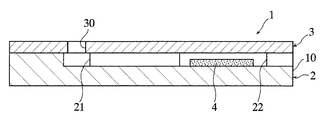
図1および図2に示した分析用具1は、いわゆるマイクロデバイスとして構成されたものである。分析用具1は、毛細管現象を利用して試料液を移動させ、かつ反応場を提供するものである。この分析用具1は、微細な流路20が形成された基板2上に、流路20を覆うようにカバー3を積層した形態をしている。流路20は、受液部21および試薬保持部22を有しているとともに、分析用具1の端面10において開放している。試薬保持部22には、試料液中の特定成分と反応させるための試薬を含んだ試薬部4が形成されている。これに対してカバー3は、基板2における受液部21に連通し、かつ流路20に試料を導入するための導入口30を有している。
【0019】
次に、本発明に係る分析用具の製造方法の基本事項を、図3ないし図8を参照して説明する。
【0020】
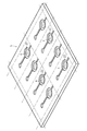
まず、図3に示したような集合基板5を形成する。この集合基板5は、仮想的な切断ラインL1,L2によって区画された複数の基板形成領域50を有している。各基板形成領域50には、試薬保持部22を有する流路20が形成されている。試薬保持部22は、たとえば深さ寸法D1が50〜200μm、容積が0.05〜5μLとなるように形成される。このような集合基板5は、樹脂材料を用いた金型成形により形成することができる。
【0021】
次に、図4に示したように集合基板5における各試薬保持部22に試薬部4を形成する。試薬部4は、試薬保持部22に対して材料液を塗布した後、これを乾燥させるといった塗布・乾燥作業を複数回行うことにより形成することができる。
【0022】
材料液の塗布は、たとえば図5に示したようにインクジェット方式を採用した吐出装置6を用いて行われる。吐出装置6としては、たとえば10〜2000pLの液滴60を吐出できるように構成されたものが使用される。この吐出装置6を使用する場合には、吐出装置6から材料液の液滴60を吐出させつつ吐出装置6を移動させ、試薬保持部22の底面22Aに対して多数の液滴60を付着させることにより材料液の塗布が行われる。このような手法により材料液の塗布を行う場合には、試薬保持部22の側面22Bから一定距離離れた領域に材料液を塗布することができる。図6(a)には、側面22Bから間隔を隔てて材料液を塗布する例を示したが、材料液を塗布すべき領域と側面22Bとの距離D2は、たとえば0.1μm以上に設定される。
【0023】
一方、材料液の乾燥は、加熱あるいは送風により行うことができる。材料液は、極力短い時間で乾燥させるのが好ましく、本実施の形態では、たとえば熱エネルギの供給により0.5〜30秒程度で材料液が乾燥させられる。熱エネルギの供給は、たとえば試料液の上方から放射熱を与えることにより行われる。放射熱の供給は、たとえば赤外線や近赤外線を発振可能な発振装置を用いて、試料液に対して赤外線や近赤外線などの光線を照射することにより行われる。もちろん、赤外線や近赤外線以外の波長の光線を照射して、試料液に放射熱を与えることにより行うようにしてもよい。熱エネルギの供給は、集合基板5の裏面に熱源を接触させて伝熱により行うようにしてもよい。このようにして材料液を乾燥させた場合、材料液の水分の蒸発によって、図6(b)に示したように、塗布した材料液よりも厚みt1が小さな薄膜40が形成される。
【0024】
材料液として、試薬を溶剤に分散させたものが好適に使用される。材料液における試薬の濃度は、たとえば0.1〜60wt%とされる。溶剤としては、典型的には水が用いられ、試薬の種類によっては有機溶剤を使用してもよい。
【0025】
各回の塗布・乾燥作業における材料液の塗布量は、試薬保持部22を先に例示した深さD1および容積に形成する場合には(図3参照)、たとえば1〜200nL塗布とされる。この場合、各回の塗布・乾燥作業においては、図6(b)に示したように厚みt1が0.1〜5μmの薄膜40が形成される。このような塗布・乾燥作業は、上述したように複数回行われ、典型的には、2回〜200回行われる。この場合、試薬部4は、厚みt2が1〜50μmに形成される(図7参照)。
【0026】
次いで、図8に示したように集合基板5に対してカバーシート7を貼着して分析用具集合体8を形成した後に、切断ラインL1,L2に沿って分析用具集合体8を切断することにより、図1および図2に示したような個々の分析用具1が得られる。
【0027】
上述した試薬部の形成工程においては、材料液の塗布・乾燥作業を複数回に分けて行うようにしている。そのため、各回の乾燥作業では材料液が早急に乾燥して図6(b)に示したように薄膜40が形成され、最終的には、図7に示したように薄膜40を積層した形態の試薬部4が形成される。各回の塗布・乾燥作業において形成される薄膜40は厚みが小さいために厚みムラが小さく、したがって、最終的に形成される試薬部4も厚みムラが小さくなる。また、試薬保持部22の側面22Bから間隔を隔てて材料液を塗布するようにすれば(図6(a)参照)、図6(b)および図7に示したように、材料液を乾燥させるときに、材料液が側面22Bに付着した状態となることを抑制することができる。その結果、薄膜40の厚みムラを小さくし、試薬部4の厚みムラを低減することができるようになる。そして、微細な試薬保持部22に対して、側面22Bと接触することなく薄膜40を形成するためには、材料液の塗布において、微量な液滴を吐出可能なインクジェット方式を採用するのが有利である。
【0028】
以上の説明から分かるように、上記した試薬部の形成工程では、サイズの小さい試薬部4であっても、試薬部4の厚みムラを小さくすることができ、試料の供給により試薬部4が溶解したときの濃度を均一化することができるようになる。このような効果は、従来のように圧力棒を用いて材料液を押さえた状態で材料液を乾燥させることなく得ることができる。この点から、圧力棒の製造に要するコストや圧力棒を厳密に操作する必要がない分だけ、上記製造方法では、試薬部4ひいては分析用具1をコスト的に有利に製造できるといえる。
【0029】
【0030】
上記した試薬部の形成工程を用いることにより、たとえば、図9(a)に参考的に示した分析用具1Aを製造することができる。この分析用具1Aでは、試薬部4Aが、試薬保持部22において、異なる試薬を含んだ第1および第2試薬層4Aa,4Abが積層された構成を有している。第2試薬層4Abは、第1試薬層4Aaの上に、水溶性の分離層4Acを介して積層されている。分離層4Acは、試薬保持部22に対して試料を供給する前に、第1試薬層4Aaに含まれる試薬と第2試薬層4Abに含まれる試薬とが混ざり合うのを抑制するためのものであり、典型的には、CMC(カルボキシメチルセルロース)により形成される。分析用具1Aでは、試薬保持部22に試料を供給した場合に、第1試薬層4Aaの試薬、第2試薬層4Abの試薬、および試料が反応する。このような分析用具1Aにおいても、各試薬層4Aa,4Abを形成する場合に、先に説明したのと同様な手法を採用することができる。
【0031】
本発明方法では、上記した試薬部の形成工程を用いることにより、図9(b)に示した分析用具1Bを製造する。この分析用具1Bは、複数種の試薬4Ba,4Bb,4Bc(図では3種類)が平面的に分離して含まれた試薬部4Bを備えたものである。なお、同図においては、説明の便宜上、各試薬4Ba,4Bb,4Bcの大きさを大幅に誇張して描いてあり、また各試薬4Ba,4Bb,4Bcは相互に重なり合うようにして試薬保持部22に保持されていてもよい。このような試薬部4Bは、たとえば試薬4Baを含む材料液を塗布した後にこれを乾燥させ、次いで試薬4Bbを含む材料液を塗布した後にこれを乾燥させ、さらに試薬4Bcを含む材料液を塗布した後にこれを乾燥させることにより形成することができる。
【0032】
図10(a)に参考的に示した分析用具1Cは、異なる試薬を含んだ複数の試薬部4Ca,4Cb,4Ccが平面的に分離して形成されたものである。一方、図10(b)に参考的に示した分析用具1Dは、凹部(試薬保持部)ではなく、全体が平面とされた基板10D上に複数の試薬部4Dが形成されたものである。これらの分析用具1C,1Dにおいても、各試薬部4Ca,4Cb,4Cc,4Dを形成する場合に、先に説明したのと同様な手法を採用することができる。
【図面の簡単な説明】
【図1】 本発明に係る製造方法により製造される分析用具の参考例を示す全体斜視図である。
【図2】 図1のII‐II線に沿う断面図である。
【図3】 集合基板の全体斜視図、および集合基板の要部拡大断面図である。
【図4】 集合基板の試薬保持部に試薬部を形成した状態を示す全体斜視図である。
【図5】 試薬保持部に対する材料液の塗布作業を説明するための図であり、吐出装置の要部概略図および集合基板の要部断面図である。
【図6】 (a)は試薬保持部に材料液を塗布した状態を示す集合基板の要部断面図であり、(b)は材料液を乾燥させた状態を示す集合基板の要部断面図である。
【図7】 試薬部が出来上がった状態を示す集合基板の要部断面図である。
【図8】 カバーシートを貼着する作業を説明するための分析用具集合体の全体斜視図である。
【図9】 (a)は分析用具の参考例を示し、(b)は、本発明方法により製造される分析用具を示す図である。
【図10】 本発明の製造対象となる分析用具の他の参考例を示す図である。
【図11】 従来における分析用具の試薬部を形成する作業の一例を説明するための断面図である。
【図12】 従来における分析用具の試薬部を形成する作業の他の例を説明するための断面図である。
【符号の説明】
1,1A〜1D 分析用具
2,10D 基板
22 試薬保持部
22A 底面(試薬保持部の)
22B 側面(試薬保持部の)
4,4A,4B,4Ca〜4Cc,4D 試薬部
6 吐出装置[0001]
BACKGROUND OF THE INVENTION
The present invention relates to a method for producing an analytical tool that is used for analyzing a specific component in a sample solution and includes a reagent part containing a reagent for reacting the specific component.
[0002]
[Prior art]
As a sample analysis method, for example, there is a method of analyzing a reaction solution obtained by reacting a sample and a reagent by an optical method. When analyzing a sample by such a technique, an analysis tool that provides a reaction field is used. And when analyzing a trace amount sample, what is called a micro device in which a fine channel was formed is used as an analysis tool. On the other hand, the reaction between the sample and the reagent in the analysis tool is performed by, for example, forming a reagent part in advance for the reaction part set in the analysis tool and supplying the sample to the reagent part.
[0003]
The reagent part of the analysis tool is formed, for example, by drying the material liquid after supplying the material liquid containing the reagent to the reaction part. The supply of the material liquid to the reaction unit is typically performed using a
[0004]
In the above-described method for forming the reagent part, when the
[0005]
In order to solve such a problem, as shown in FIG. 12, the
[0006]
[Patent Document 1]
JP 2000-229245 A [Patent Document 2]
Japanese Patent Laid-Open No. 9-101297
[Problems to be solved by the invention]
If the
[0008]
In order to minimize such thickness unevenness, it is necessary to make the size of the
[0009]
The present invention has been conceived under such circumstances, and in the case of producing an analytical tool having a reagent part, even a reagent part having a small size is advantageous in terms of cost. An object is to reduce the thickness unevenness.
[0010]
DISCLOSURE OF THE INVENTION
In the present invention, the following technical means are taken in order to solve the above-described problems. That is, the method for producing an analytical tool provided by the present invention is such that a reagent part holding portion formed on a substrate and having a bottom surface and a side surface and recessed in the thickness direction of the substrate is in close contact with the bottom surface. A method for producing an analytical tool having a reagent part forming step for forming a reagent part containing a reagent for reacting with a specific component in a sample solution, wherein the reagent part forming step is a material containing the reagent. While the liquid is applied to a region of the bottom surface that is separated from the side surface by a certain distance, the material liquid is dried several times, and the reagent part forming step includes one reagent holding. This is characterized in that a plurality of types of reagents are exposed in contact with each other so that they are all exposed .
[0011]
The multiple application / drying operations are performed 2 to 200 times using, for example, a material solution containing the same reagent. As the material liquid, for example, a liquid containing 0.1 to 60 wt% of a reagent is used.
[0012]
The analysis tool to be manufactured according to the present invention has a reagent part formed on a reagent holding part formed on a substrate, for example. In this case, the dimension in the thickness direction of the substrate on the side surface of the reagent holding portion is, for example, 50 to 200 [mu] m. The side surface of the reagent holding portion, the distance between the region for applying the material liquid is, for example, 0.1μm or more. The volume of the reagent holding unit is, for example, 0.05 to 5 μL.
[0013]
The material liquid is preferably applied using a discharge device using an inkjet method. As this discharge device, for example, a device configured to discharge a droplet of 10 to 2000 pL is used. In this case, application of the material liquid is performed by attaching a plurality of droplets to the application target site using a discharge device. The application amount of the material liquid in each application / drying operation is, for example, 1 to 200 nL.
[0014]
The material liquid is dried, for example, by supplying heat energy. The supply of thermal energy is performed by using radiant heat given by light rays such as infrared rays from above the sample solution, or by bringing a heat source into contact with the back surface of the substrate. Of course, the material liquid may be dried by blowing air.
[0015]
In each coating / drying operation, a thin layer having a thickness of 0.1 to 5 μm is formed. In the whole reagent part formation process, the thickness of a reagent part is formed in 1.0-50 micrometers, for example.
[0016]
DETAILED DESCRIPTION OF THE INVENTION
Hereinafter, preferred embodiments of the present invention will be specifically described with reference to the drawings.
[0017]
The present invention relates to a method for manufacturing an analytical tool having a reagent part having the configuration shown in FIG. 9B. Prior to the description of this manufacturing method, an example of an analytical tool to be manufactured is shown in FIG. The basic matters of the manufacturing process will be described with reference to FIGS. 3 to 8 .
[0018]
The
[0019]
Next, the basic items of the method for producing an analytical tool according to the present invention will be described with reference to FIGS.
[0020]
First, the
[0021]
Next, as shown in FIG. 4, the
[0022]
The material liquid is applied using, for example, a
[0023]
On the other hand, the material liquid can be dried by heating or blowing. The material liquid is preferably dried in as short a time as possible. In this embodiment, for example, the material liquid is dried in about 0.5 to 30 seconds by supplying heat energy. The supply of thermal energy is performed, for example, by applying radiant heat from above the sample liquid. The supply of radiant heat is performed, for example, by irradiating the sample liquid with light rays such as infrared rays and near infrared rays using an oscillation device capable of oscillating infrared rays and near infrared rays. Of course, it may be performed by irradiating the sample liquid with radiant heat by irradiating light rays having a wavelength other than infrared rays or near infrared rays. The heat energy may be supplied by heat transfer with a heat source in contact with the back surface of the
[0024]
As wood charge solution, obtained by dispersing a reagent in a solvent is preferably used. The concentration of the reagent in the material solution is, for example, 0.1 to 60 wt%. As the solvent, water is typically used, and an organic solvent may be used depending on the type of reagent.
[0025]
The application amount of the material liquid in each application / drying operation is, for example, 1 to 200 nL when the
[0026]
Next, as shown in FIG. 8, after the
[0027]
In the process of forming the reagent portion described above, and to perform separately applying and drying operation of the liquid material in a plurality of times. Therefore, in each drying operation, the material liquid is quickly dried and the
[0028]
As can be seen from the above description, in the reagent part forming step described above , even if the
[0029]
[0030]
By using the above-described reagent part forming step, for example, the analytical tool 1A shown as a reference in FIG. 9A can be manufactured. In this analysis tool 1A , the
[0031]
In the method of the present invention, the
[0032]
The analytical tool 1C shown as a reference in FIG. 10 (a) is formed by separating a plurality of reagent parts 4Ca, 4Cb, 4Cc containing different reagents in a planar manner. On the other hand, the
[Brief description of the drawings]
FIG. 1 is an overall perspective view showing a reference example of an analytical tool manufactured by a manufacturing method according to the present invention.
FIG. 2 is a cross-sectional view taken along the line II-II in FIG.
FIG. 3 is an overall perspective view of the collective substrate and an enlarged cross-sectional view of a main part of the collective substrate.
FIG. 4 is an overall perspective view showing a state in which a reagent part is formed in the reagent holding part of the collective substrate.
FIGS. 5A and 5B are diagrams for explaining an operation of applying a material liquid to the reagent holding unit, and are a schematic diagram of a main part of a discharge device and a cross-sectional view of a main part of a collective substrate.
6A is a cross-sectional view of the main part of the collective substrate showing a state in which the material liquid is applied to the reagent holding unit, and FIG. 6B is a cross-sectional view of the main part of the collective substrate showing the state in which the material liquid is dried. It is.
FIG. 7 is a cross-sectional view of a main part of the collective substrate showing a state in which a reagent part is completed.
FIG. 8 is an overall perspective view of an analysis tool assembly for explaining an operation of attaching a cover sheet.
9A shows a reference example of an analysis tool, and FIG. 9B shows an analysis tool manufactured by the method of the present invention .
FIG. 10 is a diagram showing another reference example of an analytical tool to be manufactured according to the present invention.
FIG. 11 is a cross-sectional view for explaining an example of an operation for forming a reagent part of a conventional analysis tool.
FIG. 12 is a cross-sectional view for explaining another example of a conventional operation for forming a reagent part of an analysis tool.
[Explanation of symbols]
1,1A ~
22 Reagent holder
22A Bottom (of reagent holder)
22B Side (of reagent holder)
4,4A, 4B, 4Ca-4Cc,
Claims (13)
上記試薬部形成工程は、上記試薬を含む材料液を、上記底面における上記側面から一定距離隔てた領域に対して塗布した後に上記材料液を乾燥させる複数回の塗布・乾燥作業を含んでいる一方、
上記試薬部形成工程は、一つの試薬保持部に、複数種類の試薬が、相互に接触して全て露出するようにして行うことを特徴とする、分析用具の製造方法。A reagent part holding part formed on the substrate and having a bottom surface and side surfaces and recessed in the thickness direction of the substrate includes a reagent for reacting with a specific component in the sample solution so as to be in close contact with the bottom surface. A method for producing an analytical tool having a reagent part forming step for forming a reagent part,
The reagent portion formation step, while that of the material liquid containing the reagent, including a plurality of times of coating and drying operation for drying the material liquid was applied to certain distance between each area from the side surface of the bottom ,
The method for producing an analytical tool, wherein the reagent part forming step is performed such that a plurality of types of reagents are exposed to each other in a single reagent holding part .
上記材料液の塗布は、上記吐出装置を用いて、複数の液滴を塗布対象部位に付着させることにより行われる、請求項7に記載の分析用具の製造方法。The discharge device is configured to discharge a droplet of 10 to 2000 pL,
The method of manufacturing an analytical tool according to claim 7 , wherein the application of the material liquid is performed by attaching a plurality of droplets to a site to be applied using the discharge device.
上記試薬部形成工程の全体においては、上記試薬部の厚みが1.0〜50.0μmに形成される、請求項1ないし12のいずれかに記載の分析用具の製造方法。In each of the above application / drying operations, a thin layer having a thickness of 0.1 to 5.0 μm is formed, and
The method for producing an analytical tool according to any one of claims 1 to 12 , wherein a thickness of the reagent part is formed to 1.0 to 50.0 µm in the whole reagent part forming step.
Priority Applications (8)
| Application Number | Priority Date | Filing Date | Title |
|---|---|---|---|
| JP2002350197A JP4253178B2 (en) | 2002-12-02 | 2002-12-02 | Method for manufacturing analytical tool |
| EP03812694A EP1571446B1 (en) | 2002-12-02 | 2003-12-01 | Method for manufacturing tool for analysis |
| US10/537,391 US20060057740A1 (en) | 2002-12-02 | 2003-12-01 | Method for manufacturing tool for analysis |
| AU2003302816A AU2003302816A1 (en) | 2002-12-02 | 2003-12-01 | Method for manufacturing tool for analysis |
| PCT/JP2003/015357 WO2004053480A1 (en) | 2002-12-02 | 2003-12-01 | Method for manufacturing tool for analysis |
| CN2003801048741A CN1742199B (en) | 2002-12-02 | 2003-12-01 | Method for manufacturing tool for analysis |
| DE60336261T DE60336261D1 (en) | 2002-12-02 | 2003-12-01 | METHOD FOR PRODUCING TOOLS FOR ANALYSIS |
| AT03812694T ATE500500T1 (en) | 2002-12-02 | 2003-12-01 | METHOD FOR PRODUCING TOOLS FOR ANALYSIS |
Applications Claiming Priority (1)
| Application Number | Priority Date | Filing Date | Title |
|---|---|---|---|
| JP2002350197A JP4253178B2 (en) | 2002-12-02 | 2002-12-02 | Method for manufacturing analytical tool |
Publications (3)
| Publication Number | Publication Date |
|---|---|
| JP2004184180A JP2004184180A (en) | 2004-07-02 |
| JP2004184180A5 JP2004184180A5 (en) | 2006-02-02 |
| JP4253178B2 true JP4253178B2 (en) | 2009-04-08 |
Family
ID=32500748
Family Applications (1)
| Application Number | Title | Priority Date | Filing Date |
|---|---|---|---|
| JP2002350197A Expired - Lifetime JP4253178B2 (en) | 2002-12-02 | 2002-12-02 | Method for manufacturing analytical tool |
Country Status (8)
| Country | Link |
|---|---|
| US (1) | US20060057740A1 (en) |
| EP (1) | EP1571446B1 (en) |
| JP (1) | JP4253178B2 (en) |
| CN (1) | CN1742199B (en) |
| AT (1) | ATE500500T1 (en) |
| AU (1) | AU2003302816A1 (en) |
| DE (1) | DE60336261D1 (en) |
| WO (1) | WO2004053480A1 (en) |
Families Citing this family (11)
| Publication number | Priority date | Publication date | Assignee | Title |
|---|---|---|---|---|
| US20080101991A1 (en) * | 2005-06-23 | 2008-05-01 | Arkray, Inc. | Analysis Tool |
| JP4721414B2 (en) | 2005-08-15 | 2011-07-13 | キヤノン株式会社 | REACTION CARTRIDGE, REACTOR, AND METHOD FOR TRANSFERRING REACTION CARTRIDGE SOLUTION |
| JPWO2007052647A1 (en) * | 2005-11-01 | 2009-04-30 | パナソニック株式会社 | Sample solution analysis disk and mixed sample solution analysis method |
| JP2008128907A (en) * | 2006-11-22 | 2008-06-05 | Fujifilm Corp | Micro channel chip |
| JP5205922B2 (en) * | 2007-11-07 | 2013-06-05 | セイコーエプソン株式会社 | Biological material detection chip and method for manufacturing biological material detection chip |
| CN101623660B (en) * | 2008-07-09 | 2014-04-02 | 微点生物技术有限公司 | Analysis spraying canister having liquid stream control |
| WO2010005467A2 (en) | 2008-07-09 | 2010-01-14 | Micropoint Bioscience Inc | Analytical cartridge with fluid flow control |
| WO2012001972A1 (en) * | 2010-06-30 | 2012-01-05 | 株式会社メタボスクリーン | Microchemical chip, method for producing same, and method for using same |
| JP5698085B2 (en) * | 2010-07-12 | 2015-04-08 | アークレイ株式会社 | Biosensor and manufacturing method thereof |
| JP5545255B2 (en) * | 2011-03-31 | 2014-07-09 | 株式会社島津製作所 | Microchip and manufacturing method thereof |
| JP7206645B2 (en) * | 2018-06-08 | 2023-01-18 | 株式会社島津製作所 | Fluidic device manufacturing method and fluidic device |
Family Cites Families (35)
| Publication number | Priority date | Publication date | Assignee | Title |
|---|---|---|---|---|
| US4025669A (en) * | 1973-11-15 | 1977-05-24 | Owens-Illinois, Inc. | Multiple pass method of applying printing paste upon a substrate |
| US3975162A (en) * | 1974-03-13 | 1976-08-17 | Marine Colloids, Inc. | Applying reagent to medium and device therefor |
| CA1054034A (en) * | 1975-06-20 | 1979-05-08 | Barbara J. Bruschi | Multilayer analytical element |
| US4234316A (en) * | 1979-04-02 | 1980-11-18 | Fmc Corporation | Device for delivering measured quantities of reagents into assay medium |
| US4258000A (en) * | 1979-08-02 | 1981-03-24 | Obermayer Arthur S | Toxic-monitoring badge and method of use |
| US4387164A (en) * | 1980-11-05 | 1983-06-07 | Fmc Corporation | Method and apparatus for chemical analysis using reactive reagents dispersed in soluble film |
| US4753531A (en) * | 1983-11-29 | 1988-06-28 | Fuji Photo Film Co., Ltd. | Flat container type analytical instrument |
| US5178831A (en) * | 1986-10-08 | 1993-01-12 | Dai Nippon Insatsu Kab Ushiki Kaisha | Device for testing body fluids |
| US5047206A (en) * | 1987-03-11 | 1991-09-10 | Wayne State University | Reagent test strip |
| DE3902402C1 (en) * | 1989-01-27 | 1990-06-13 | Draegerwerk Ag, 2400 Luebeck, De | |
| JPH0331749A (en) * | 1989-06-29 | 1991-02-12 | Fuji Photo Film Co Ltd | Biochemical analysis apparatus and method for using this apparatus |
| US5212060A (en) * | 1990-04-27 | 1993-05-18 | Genesis Labs, Inc. | Dry test strip comprising a dextran barrier for excluding erythrocytes |
| DE4024544A1 (en) * | 1990-08-02 | 1992-02-06 | Boehringer Mannheim Gmbh | ANALYZING ELEMENT AND METHOD FOR THE PRODUCTION THEREOF |
| DE4303860C2 (en) * | 1993-02-10 | 1995-11-09 | Draegerwerk Ag | Carrier for colorimetric gas detection in composite film construction |
| WO1995006868A1 (en) * | 1993-08-31 | 1995-03-09 | Boehringer Mannheim Corporation | Reagent and method of its use |
| GB9405744D0 (en) * | 1994-03-23 | 1994-05-11 | Rolls Royce Plc | A multilayer erosion resistant coating and a method for its production |
| US5639428A (en) * | 1994-07-19 | 1997-06-17 | Becton Dickinson And Company | Method and apparatus for fully automated nucleic acid amplification, nucleic acid assay and immunoassay |
| CA2156226C (en) * | 1994-08-25 | 1999-02-23 | Takayuki Taguchi | Biological fluid analyzing device and method |
| JPH08247946A (en) * | 1995-03-14 | 1996-09-27 | Kdk Corp | Test piece used for reflectometer |
| EP1291441A3 (en) * | 1995-09-12 | 2003-03-19 | Becton, Dickinson and Company | Device and method for DNA amplification and assay |
| US5916524A (en) * | 1997-07-23 | 1999-06-29 | Bio-Dot, Inc. | Dispensing apparatus having improved dynamic range |
| US6113855A (en) * | 1996-11-15 | 2000-09-05 | Biosite Diagnostics, Inc. | Devices comprising multiple capillarity inducing surfaces |
| EP1046912A1 (en) * | 1997-10-27 | 2000-10-25 | Idexx Laboratories, Inc. | Device and methods for determination of analyte in a solution |
| JP3350421B2 (en) * | 1997-11-06 | 2002-11-25 | 日立ソフトウエアエンジニアリング株式会社 | Biochip reader and biochip reading method |
| US6117396A (en) * | 1998-02-18 | 2000-09-12 | Orchid Biocomputer, Inc. | Device for delivering defined volumes |
| US6830934B1 (en) * | 1999-06-15 | 2004-12-14 | Lifescan, Inc. | Microdroplet dispensing for a medical diagnostic device |
| US6296811B1 (en) * | 1998-12-10 | 2001-10-02 | Aurora Biosciences Corporation | Fluid dispenser and dispensing methods |
| JP2000229245A (en) * | 1999-02-09 | 2000-08-22 | Seiko Epson Corp | Microchemical reaction device |
| DE19923761C1 (en) * | 1999-05-21 | 2001-02-08 | Bruker Daltonik Gmbh | Processing of sample molecules of liquids, involves making the sample droplets stand or suspend from lyophilic or lyophobic anchors on flat support surfaces |
| US6696240B1 (en) * | 1999-10-26 | 2004-02-24 | Micronix, Inc. | Capillary test strip to separate particulates |
| US6420180B1 (en) * | 2000-01-26 | 2002-07-16 | Agilent Technologies, Inc. | Multiple pass deposition for chemical array fabrication |
| JP2002144555A (en) * | 2000-08-31 | 2002-05-21 | Riso Kagaku Corp | Ink-jet printer and thick film printing method for the printer |
| JP2002340914A (en) * | 2001-03-14 | 2002-11-27 | Kawamura Inst Of Chem Res | Micronozzle, method for manufacturing the same, spotting method and spotter |
| JP2003133691A (en) * | 2001-10-22 | 2003-05-09 | Seiko Epson Corp | Method and device for forming film pattern, conductive film wiring, electro-optical device, electronic equipment, and non-contact card medium |
| US20030157503A1 (en) * | 2003-04-04 | 2003-08-21 | Mcgarry Mark W | Compositions and methods for performing biological reactions |
-
2002
- 2002-12-02 JP JP2002350197A patent/JP4253178B2/en not_active Expired - Lifetime
-
2003
- 2003-12-01 EP EP03812694A patent/EP1571446B1/en not_active Expired - Lifetime
- 2003-12-01 AT AT03812694T patent/ATE500500T1/en not_active IP Right Cessation
- 2003-12-01 CN CN2003801048741A patent/CN1742199B/en not_active Expired - Lifetime
- 2003-12-01 AU AU2003302816A patent/AU2003302816A1/en not_active Abandoned
- 2003-12-01 WO PCT/JP2003/015357 patent/WO2004053480A1/en active Application Filing
- 2003-12-01 US US10/537,391 patent/US20060057740A1/en not_active Abandoned
- 2003-12-01 DE DE60336261T patent/DE60336261D1/en not_active Expired - Lifetime
Also Published As
| Publication number | Publication date |
|---|---|
| ATE500500T1 (en) | 2011-03-15 |
| CN1742199A (en) | 2006-03-01 |
| CN1742199B (en) | 2012-06-13 |
| EP1571446A1 (en) | 2005-09-07 |
| EP1571446A4 (en) | 2006-02-22 |
| WO2004053480A1 (en) | 2004-06-24 |
| DE60336261D1 (en) | 2011-04-14 |
| EP1571446B1 (en) | 2011-03-02 |
| AU2003302816A1 (en) | 2004-06-30 |
| JP2004184180A (en) | 2004-07-02 |
| US20060057740A1 (en) | 2006-03-16 |
Similar Documents
| Publication | Publication Date | Title |
|---|---|---|
| JP4253178B2 (en) | Method for manufacturing analytical tool | |
| US20030224531A1 (en) | Microplate with an integrated microfluidic system for parallel processing minute volumes of fluids | |
| US20060103051A1 (en) | Microfluidic array devices and methods of manufacture thereof | |
| JP4681052B2 (en) | Flow cell and manufacturing method thereof | |
| US11148942B2 (en) | Three-dimensional features formed in molded panel | |
| US6386219B1 (en) | Fluid handling system and method of manufacture | |
| JP2005030906A (en) | Analytical chip and analyzing method | |
| US20180001317A1 (en) | Tip overlay for continuous flow spotting apparatus | |
| US20080101991A1 (en) | Analysis Tool | |
| EP2049260B1 (en) | Channelless fluidic sample transport medium | |
| JP4383446B2 (en) | Method for bonding microstructured substrates | |
| US20030224506A1 (en) | Tiled biochips and the methods of making the same | |
| US20080241956A1 (en) | Method for detecting analyte and biochip | |
| US20090081768A1 (en) | Devices and Methods for Thermally Isolating Chambers of an Assay Card | |
| JP4009683B2 (en) | Method for manufacturing analytical tool | |
| US7479197B2 (en) | Thin-layer cell | |
| JP2004243193A (en) | Labo-on-a-chip, method for manufacturing the sane and apparatus for the same | |
| US11318458B2 (en) | Cassette substrates made of polyetherimide | |
| US20140157867A1 (en) | Gas chromatography chip and multi-layered gas chromatography chip assembly thereof | |
| KR20130092598A (en) | Method for manufacturing fluid-detecting test piece | |
| WO2022201469A1 (en) | Liquid handling device, liquid handling system and liquid handling method | |
| JP2000229245A (en) | Microchemical reaction device | |
| JP2017193014A (en) | Manufacturing method of microchannel device | |
| KR20030045221A (en) | Method for manufacturing head of ink jet printer | |
| IT202100027521A1 (en) | BIO ANALYSIS CHIP, BIO ANALYSIS SYSTEM AND CHIP MANUFACTURING PROCEDURE |
Legal Events
| Date | Code | Title | Description |
|---|---|---|---|
| A521 | Request for written amendment filed |
Free format text: JAPANESE INTERMEDIATE CODE: A523 Effective date: 20051130 |
|
| A621 | Written request for application examination |
Free format text: JAPANESE INTERMEDIATE CODE: A621 Effective date: 20051130 |
|
| A131 | Notification of reasons for refusal |
Free format text: JAPANESE INTERMEDIATE CODE: A131 Effective date: 20081014 |
|
| A521 | Request for written amendment filed |
Free format text: JAPANESE INTERMEDIATE CODE: A523 Effective date: 20081212 |
|
| TRDD | Decision of grant or rejection written | ||
| A01 | Written decision to grant a patent or to grant a registration (utility model) |
Free format text: JAPANESE INTERMEDIATE CODE: A01 Effective date: 20090120 |
|
| A01 | Written decision to grant a patent or to grant a registration (utility model) |
Free format text: JAPANESE INTERMEDIATE CODE: A01 |
|
| A61 | First payment of annual fees (during grant procedure) |
Free format text: JAPANESE INTERMEDIATE CODE: A61 Effective date: 20090123 |
|
| R150 | Certificate of patent or registration of utility model |
Ref document number: 4253178 Country of ref document: JP Free format text: JAPANESE INTERMEDIATE CODE: R150 Free format text: JAPANESE INTERMEDIATE CODE: R150 |
|
| FPAY | Renewal fee payment (event date is renewal date of database) |
Free format text: PAYMENT UNTIL: 20120130 Year of fee payment: 3 |
|
| FPAY | Renewal fee payment (event date is renewal date of database) |
Free format text: PAYMENT UNTIL: 20120130 Year of fee payment: 3 |
|
| FPAY | Renewal fee payment (event date is renewal date of database) |
Free format text: PAYMENT UNTIL: 20120130 Year of fee payment: 3 |
|
| FPAY | Renewal fee payment (event date is renewal date of database) |
Free format text: PAYMENT UNTIL: 20130130 Year of fee payment: 4 |
|
| R250 | Receipt of annual fees |
Free format text: JAPANESE INTERMEDIATE CODE: R250 |
|
| FPAY | Renewal fee payment (event date is renewal date of database) |
Free format text: PAYMENT UNTIL: 20140130 Year of fee payment: 5 |
|
| R250 | Receipt of annual fees |
Free format text: JAPANESE INTERMEDIATE CODE: R250 |
|
| R250 | Receipt of annual fees |
Free format text: JAPANESE INTERMEDIATE CODE: R250 |
|
| R250 | Receipt of annual fees |
Free format text: JAPANESE INTERMEDIATE CODE: R250 |
|
| R250 | Receipt of annual fees |
Free format text: JAPANESE INTERMEDIATE CODE: R250 |
|
| R250 | Receipt of annual fees |
Free format text: JAPANESE INTERMEDIATE CODE: R250 |
|
| R250 | Receipt of annual fees |
Free format text: JAPANESE INTERMEDIATE CODE: R250 |
|
| R250 | Receipt of annual fees |
Free format text: JAPANESE INTERMEDIATE CODE: R250 |
|
| R250 | Receipt of annual fees |
Free format text: JAPANESE INTERMEDIATE CODE: R250 |
|
| R250 | Receipt of annual fees |
Free format text: JAPANESE INTERMEDIATE CODE: R250 |
|
| R250 | Receipt of annual fees |
Free format text: JAPANESE INTERMEDIATE CODE: R250 |
|
| EXPY | Cancellation because of completion of term |