JP4251243B2 - Area expansion device - Google Patents
Area expansion device Download PDFInfo
- Publication number
- JP4251243B2 JP4251243B2 JP33577598A JP33577598A JP4251243B2 JP 4251243 B2 JP4251243 B2 JP 4251243B2 JP 33577598 A JP33577598 A JP 33577598A JP 33577598 A JP33577598 A JP 33577598A JP 4251243 B2 JP4251243 B2 JP 4251243B2
- Authority
- JP
- Japan
- Prior art keywords
- region
- point
- direction vector
- interest
- expansion
- Prior art date
- Legal status (The legal status is an assumption and is not a legal conclusion. Google has not performed a legal analysis and makes no representation as to the accuracy of the status listed.)
- Expired - Fee Related
Links
Images


Description
【0001】
【発明の属する技術分野】
本発明は領域拡張装置に係り、特にリージョングローイング法において領域を拡張し臓器領域を抽出する領域拡張装置に関する。
【0002】
【従来の技術】
リージョングローイング法は、抽出領域のある点から同一領域に属すると思われる連結領域に対して順次、領域拡張を行い、関心領域を抽出する方法である。
従来では、拡張条件として、大域的な濃度変化の許容範囲α(以後、グローバルレンジと呼ぶ)内、局所的な許容範囲β(以後、ローカルレンジと呼ぶ)内であれば、同一領域とみなしていた。式1にその拡張条件を示す。
【0003】
【数1】
|fx −f0 |<α かつ |fx −fi |<β …式1
式1においてfi はi番目の拡張で抽出された点Pi の濃度値、fx は点Pi に隣接する点の濃度値、f0 はリージョングローイングの開始点P0 の濃度値を示す。
【0004】
【発明が解決しようとする課題】
しかしながら、従来の方法では、ただボクセルの集合として領域を拡張するので、血管形状などの構造解析ができないという問題がある。
また、拡張条件の設定を拡張処理前に経験的に決定しているため、関心領域の詳細な抽出は困難であるという欠点がある。
【0005】
本発明はこのような事情に鑑みてなされたもので、誤った拡張を軽減し、かつ関心領域を細部まで抽出することのできる領域拡張装置を提供することを目的としている。
【0006】
【課題を解決する為の手段】
本発明は前記目的を達成するために、リージョングローイング法によって関心領域を抽出する領域拡張装置において、関心領域の点として抽出すべきか否かを判断する対象点が、該対象点の近傍点の情報に基づいてどの方向に拡張されるかの指標となる走行方向ベクトルを求める走行方向ベクトル算出手段と、前記走行方向ベクトル算出手段によって求められた現抽出時点との前抽出時点の間の走行方向ベクトルに基づいて関心領域が分割されているか否かを判断する判断手段と、前記判断手段によって前記関心領域が分割されていると判断された場合、各分割された領域ごとに平均的な走行方向ベクトルを算出する手段と、前記算出された平均的な走行方向ベクトルの方向への領域拡張を促すように前記リージョングローイング法によって対象領域を拡張する際の拡張条件を設定する設定手段と、を備えたことを特徴とする。
【0007】
本発明によれば、走行方向ベクトル算出手段が、関心領域の点として抽出すべきか否かを判断する対象点が、該対象点の近傍点の情報に基づいてどの方向に拡張されるかの指標となる走行方向ベクトルを求める。分岐検出手段は、所定の抽出時点間に走行方向ベクトル算出手段によって求めた複数の点の走行方向ベクトルに基づいて関心領域の分岐の有無を検出し、前記関心領域の分岐が検出されると、平均走行ベクトル算出手段が各分岐した領域ごとに区分された複数の点の走行方向ベクトルの平均的な走行ベクトルを算出する。拡張条件設定手段は、リージョングローイング法によって対象点を拡張する際に平均走行ベクトル算出手段によって求めた平均走行方向ベクトルの方向への領域拡張を促すように拡張条件を設定する。このように、分岐した領域ごとに平均的な走行ベクトルを算出し、この平均走行方向ベクトルの方向への領域拡張を促すように拡張条件を設定することによって、誤った拡張を軽減でき、かつ関心領域を細部まで抽出することができる。
【0008】
【発明の実施の形態】
以下添付図面に従って本発明に係る領域拡張装置の好ましい実施の形態について詳説する。
本発明の領域拡張装置では、従来の拡張条件に新たな制約条件を追加する。この制約条件は、まず、注目するボクセル(以後、注目点とする)の各近傍ボクセル(以後、対象点とする)と他の近傍ボクセル(以後、近傍点とする)との相対関係を考えることにある。
【0009】
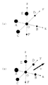
図1は、注目点と近傍点との濃度関係を示す説明図である。図1(a)、(b)においてx、y、zは三次元座標系の各軸であり、注目点Oは原点、近傍点(A、B、C、D、E、F)はx、y、z軸上に位置する。また、これらの図において、各点の大きさは各点の濃度値に比例する。各点は従来の拡張条件を満足し従来では拡張される点であるため、各点の大域的な濃度変化は前記グローバルレンジαを下回らない。
【0010】
本発明の領域拡張装置では、図1(a)に示す濃度関係の場合、対象点をBとすると、この点Bは点A、C、E、Oと比較してあまりにも小さいので、点Bの方向へ拡張しないように削除する。点D、Fも同様に削除する。削除のための評価関数を式2に示す。
【0011】
【数2】
5
S=(fi −fx )+(n1 −fx )/2+{Σ(nj −fx )}/√2
J=2 …式2
fi は注目点Oの濃度値、fx は対象点の濃度値、n1 は対象点の対角ボクセルの濃度値、nj は他の近傍点の濃度値である。
【0012】
この評価関数Sは、各ボクセルの濃度差にボクセル間の距離の逆数を乗じたものの総和である。各ボクセル間の距離は、対象点から注目点Oまでで1、対象点から対角ボクセルまでで2、対象点から他の近傍点までで√2である。式2から距離が近いほど濃度値の差分の大きさに大きく影響することが分かる。また、この評価関数Sにおいて、従来の拡張条件で満足しなかったボクセルの差分演算は式から除かれる。
【0013】
削除条件ρを式3に示し、S>ρの場合、対象点を削除する。
【0014】
【数3】
ρ=β(1+1/2) …式3
ρは注目点が近傍点と図1(b)に示すような相対関係である場合に削除条件が限界値に達していることを意味する。つまりこの削除条件は、注目点をBとすると、点Aとの濃度差と点Oとの濃度差がローカルレンジβであり、その他の点との濃度差が0の場合の評価関数Sに等しい。この追加条件は従来のグローバルレンジα、ローカルレンジβの設定を誤った場合や拡張領域が細部にまで及んだ場合での拡張の誤りを軽減することができる。
【0015】
次に、注目点に走行方向ベクトルを付加することを考える。これは、後に関心領域を抽出するための参照情報(指標)となる。注目点は上述で削除したボクセル以外について考える。走行方向ベクトル(Gx、Gy、Gz)を式4に示す。
【0016】
【数4】
Gxn =Gxn-1 +Lx+Dx
Gyn =Gyn-1 +Ly+Dy
Gzn =Gzn-1 +Lz+Dz …式4
式4においてGn-1 は前抽出時点の走行方向ベクトル(以後、前走行方向ベクトル)であり、Lは前抽出時点の位置ベクトル(以後、拡張方向ベクトル)であり、Dは拡張方向のボクセルが上記の条件によって削除されたボクセルであった場合の拡張方向ベクトルに垂直な方向ベクトル(以後、拡散方向ベクトル)を示す。これは、ボクセルが削除されることによって拡張が止まり、今までの拡張方向ベクトルをその垂直方向に拡散させているベクトルを表している。また、これらのベクトルは注目点の6近傍について用いる。
【0017】
図2は、対象領域内部からリージョングローイングを行った場合の抽出履歴データと対象点の方向ベクトルとを示す説明図であり、実際は3次元であるが2次元で表現している。同図において、各格子はボクセルを示し、各格子内の数字は抽出時点を示し、抽出時点が0のボクセルはリージョングローイングを開始するシード点(拡張元)である。この拡張元以外の各格子内の矢印は走行方向ベクトルを示している。例えば、吹き出し内の抽出時点6のボクセルに注目した場合、そのボクセルの6近傍には2つの前抽出時点5a、5bのボクセルが存在する。その各ボクセルの前走行方向ベクトルGn-1 は各々Gan-1 、Gbn-1 であり、拡張方向ベクトルLは各々La、Lbである。また、右方向に拡張できないため、拡散方向ベクトルDは上向きと下向きとがあるが、上向きには抽出時点5aの拡張方向ベクトルと逆方向であるため相殺され、下向きにのみ拡散しその拡散方向ベクトルはDaである。前記式4より、このボクセルの走行方向ベクトルGn は前走行方向ベクトルGan-1 、Gbn-1 、拡張方向ベクトルLa、Lb、拡散方向ベクトルDaの総和によって求められる。
【0018】
図3は、各ボクセルに走行方向ベクトルGn を付加する処理のフローチャートである。
まず、マウスで臓器領域内部の1点をクリックし、その1点をシード点(拡張元)としてリージョングローイングを開始する(ステップS1)。
リージョングローイングにおいて、拡張元6近傍の拡張点の判定を行う(ステップS2)。
【0019】
次に拡張元において、削除条件により拡張点の判定を行う(ステップS3)。同抽出時点の判定が終わった後、同抽出時点の拡張が終了したか判断し(ステップS4)、6近傍の各々のボクセルについて、前抽出時点に対する位置ベクトルLを求め(ステップS5)、拡散方向ベクトルDを求め(ステップS6)、前抽出時点の拡張方向ベクトルGn-1 を求める(ステップS7)。ステップS5、S6、S7で求めた位置ベクトルLと拡散方向ベクトルDと前抽出時点の拡張方向ベクトルGn-1 との総和によって走行方向ベクトルGn を求める(ステップS8)。
【0020】
さらに、そのボクセルの拡張元以外の5近傍において、拡張元と同じ抽出時点のボクセルがあるかを判断する(ステップS9)。ボクセルがある場合は、ステップS5に戻り、このボクセルに対する各ベクトルを求めて走行方向ベクトルGn に加算する。
ボクセルがない場合は、拡張点を拡張元として拡張を行い(ステップS10)、終了条件を満たすかを判断する(ステップS11)。終了条件を満たさない場合はステップS2に戻り再び処理を続け、満たす場合は処理を終了する。
【0021】
次に、上記で求められた各ボクセルの走行方向ベクトルGn から、臓器領域の分岐地点の平均的な走行方向ベクトルを求め、関心領域を抽出するための参照情報(指標)とすることを考える。ここで、参照情報はある抽出時点間毎に求めるため、上記の走行方向ベクトル抽出処理の途中で行われる。
図5は、参照情報を求める手順を示すフローチャートである。
【0022】
まず、ある抽出時点間の走行方向ベクトルを求める(ステップS21)。求めた走行方向ベクトルを極座標に変換し(ステップS22)、プロットすると図4に示すような点集合となる。この例は明らかに二分岐となる血管であり、この点集合を2つに分割することで臓器領域の分岐地点の平均的な走行方向ベクトルを求めることができる。そのために、図4のように4つの方向へ投射したヒストグラムを求める(ステップS23)。この内、最も分散の大きな2つのヒストグラムの谷に垂直な直線f、gを求める(ステップS24)。この直線f、gによって分割されたベクトルの集合から平均的な走行方向ベクトルを求める。ここで、ヒストグラムの谷を求める方法に分散比を最大にするしきい値設定法を採用する。この方法は画像を2つのクラスC1並びにC2に分割する場合、式5に示す分散度η(T)が最大になるようにしきい値Tを選定する。
【0023】
【数5】
η(T)= [σB 2 (T)/ σW 2 (T)]MAX …式5
ここで、σB 2 (T)はクラス間分散、σW 2 (T)はクラス内分散で、これらは各々式6、式7で与えられる。
【0024】
【数6】

【数7】
【0026】
次にその抽出時点間において領域が分割されているかを判断し(ステップS25)、分割されていない場合にはステップS21に戻り同様の手順を繰り返す。分割されている場合は、最後に抽出された時点のボクセルをクラスタリングする(ステップS26)。そのクラスが上記の直線f、gに分割されているかを判断し(ステップS27)、分割されていない場合はステップS21に戻り同様の手順を繰り返す。
【0027】
完全に分割されている場合には、点集合は分割されたものとして、各々の平均的な走行方向ベクトルVを求める(ステップS28)。その後、点集合毎の最後に抽出された時点のボクセルを起点として各々領域拡張をする。また、この起点を代表点とする(ステップS29)。代表点は、関心領域を求めるための指標の1つとなる。このように領域拡張をしながら、分岐地点での走行方向ベクトルと代表点を求めることによって、臓器領域の構造解析が行なえ、関心領域を求めるための指標とすることができる。終了かを判断し(ステップS30)、終了しない場合はステップS21に戻り、終了するまで前述の手順を繰り返す。
【0028】
次に、この参照領域の情報を基に関心領域を求めることについて考える。これは、上記より求められた参照領域の走行方向ベクトルから拡張条件を変更して関心領域を精度よく抽出する方法である。
図7は、関心領域抽出処理の手順を示すフローチャートである。
まず、領域拡張を行い(ステップS41)、関心領域については参照領域と同様の方法で分岐地点での走行方向ベクトルと代表点を求める(ステップS42)。ここで、関心領域の代表点に最も近い参照領域の代表点(例えば、a、b)の走行方向ベクトルとの内積が大きい方のベクトルを用いて、その走行方向ベクトルを含む象限の濃度値を注目点の濃度値に近付けること、また、方向ベクトルを含まない象限の濃度値を注目点の濃度値から遠ざけることを考える(ステップS43)。図6(b)を用いて説明すると、拡張元を点Oとして、走行方向ベクトルをVとする場合(ステップS44)、その象限に属する点B,D,Eの濃度値を注目点Oに近付け、その象限に属さない点A,Fの濃度値を注目点Oから遠ざける。言い換えれば、従来の拡張条件を参照領域の走行方向ベクトルに依存した値に変更することを考えることと等しい。新しい拡張条件を式8で表現する(ステップS45)。
【0029】
【数8】
|fx −f0 |<α+ξ|fx −fi | かつ
|fx −fi |<β+ξ|fx −fi | …式8
fi はi番目の拡張で抽出された点Piの濃度値、fx はPiに隣接する点 の濃度値、fo はリージョングローイングの開始点Po の濃度値、ξは参照領 域の走行方向ベクトルと注目点に対する近傍点の位置ベクトルとの内積である 。
【0030】
式8は式9を式1の従来の拡張条件に代入した式である。
【0031】
【数9】
fx −ξ|fx −fi |→fx …式9
fx は変更後のPiに隣接する点の濃度値である。また、同時に式2、式3に式9を代入して、余計な拡張点を削除するための評価関数Sおよび削除条件ρを変更する(ステップS46)。それらを式10、式11に示す。
【0032】
【数10】
【数11】
ρ={β+ξ|fx −fi |}(1+1/2) …式11
これがS>ρ場合、対象点を削除する。この新しい拡張条件、削除条件に変更し、より参照情報に依存した拡張を促し、関心領域を細部まで抽出する。
図8は、本発明の領域拡張装置のハードウエア構成を示すブロック図である。
【0034】
この領域拡張装置は、例えばX線CT装置やMRI装置などの医用画像診断装置で被検体の対象部位について収集した医用画像データを記録し表示するもので、各構成要素の動作を制御する中央演算処理装置(CPU)50と、装置の制御プログラムが格納された主メモリ52と、臓器領域抽出処理プログラム等が格納された磁気ディスク54と、画像データを表示するために記憶する表示メモリ56と、この表示メモリ56からの画像データを表示する表示装置としてのCRT58と、位置入力装置としてのマウス62と、マウス62の状態を検出してCRT58上のマウスポインタの位置やマウス62の状態等の信号をCPU50に出力するマウスコントローラ60とから上記各構成要素を接続する共通バス64とから構成される。
【0035】
【発明の効果】
以上説明したように本発明に係る領域拡張装置によれば、平均走行ベクトル算出手段が分岐した領域ごとに平均的な走行ベクトルを算出し、拡張条件設定手段がこの平均走行方向ベクトルの方向への領域拡張を促すように拡張条件を設定することによって、誤った拡張を軽減でき、かつ関心領域を細部まで抽出することができる。
【図面の簡単な説明】
【図1】注目点と近傍点との濃度関係を示す説明図
【図2】対象領域内部からリージョングローイングを行った場合の抽出履歴データと対象点の方向ベクトルとを示す説明図
【図3】各ボクセルに走行方向ベクトルを付加する処理のフローチャート
【図4】平均的な走行方向ベクトルを求めるためのヒストグラムを示す図
【図5】参照情報を求める手順を示すフローチャート
【図6】従来の拡張条件を変更するための条件を示す説明図
【図7】関心領域抽出処理の手順を示すフローチャート
【図8】本発明の領域拡張装置のハードウエア構成を示すブロック図
【符号の説明】
50…中央演算処理装置(CPU)
52…主メモリ
54…磁気ディスク
56…表示メモリ
58…CRT
60…コントローラ
62…マウス[0001]
BACKGROUND OF THE INVENTION
The present invention relates to a region expanding device, and more particularly to a region expanding device that expands a region and extracts an organ region in a region growing method.
[0002]
[Prior art]
The region growing method is a method of extracting a region of interest by sequentially expanding a connected region that seems to belong to the same region from a certain point of the extraction region.
Conventionally, if the expansion condition is within the allowable range α of global density change (hereinafter referred to as the global range) and within the local allowable range β (hereinafter referred to as the local range), it is regarded as the same region. It was.
[0003]
[Expression 1]
| F x −f 0 | <α and | f x −f i | <β (1)
In
[0004]
[Problems to be solved by the invention]
However, in the conventional method, since the region is expanded only as a set of voxels, there is a problem that a structural analysis such as a blood vessel shape cannot be performed.
Moreover, since the setting of the expansion condition is determined empirically before the expansion process, there is a drawback that it is difficult to extract the region of interest in detail.
[0005]
The present invention has been made in view of such circumstances, and an object of the present invention is to provide a region expansion device that can reduce erroneous expansion and extract a region of interest in detail.
[0006]
[Means for solving the problems]
In order to achieve the above object, the present invention provides a region expanding apparatus for extracting a region of interest by a region growing method, wherein a target point for determining whether or not to extract as a point of a region of interest is information on neighboring points of the target point. running direction between the pre-extraction point of the traveling direction vector calculating means for determining a traveling direction vector of the one of the indicator is extended in any direction, the current extraction point obtained by the previous SL traveling direction vector calculation means on the basis of the judgment means for region of interest to determine whether it is divided on the basis of the vector, if the region of interest is determined to be divided by said determining means, flat Hitoshiteki travel for each divided area hand stage calculate a direction vector, by the region growing method to encourage area expansion in the direction of the average traveling direction vector the calculated And setting means to set the extended conditions for expanding the elephant area, further comprising a characterized.
[0007]
According to the present invention, the direction in which the target point from which the traveling direction vector calculation means determines whether or not to extract as a point of interest is expanded based on the information of the neighboring points of the target point Find the travel direction vector. The branch detection means detects the presence / absence of a branch of the region of interest based on the travel direction vectors of a plurality of points obtained by the travel direction vector calculation means during a predetermined extraction time point, and when the branch of the region of interest is detected, The average travel vector calculation means calculates an average travel vector of travel direction vectors of a plurality of points divided for each branched area. The expansion condition setting means sets the expansion condition so as to promote the area expansion in the direction of the average travel direction vector obtained by the average travel vector calculation means when the target point is expanded by the region growing method. In this way, by calculating an average travel vector for each branched area and setting an expansion condition to promote area expansion in the direction of this average travel direction vector, erroneous expansion can be reduced and interest can be reduced. The region can be extracted to details.
[0008]
DETAILED DESCRIPTION OF THE INVENTION
The preferred embodiments of the area expanding apparatus according to the present invention will be described below in detail with reference to the accompanying drawings.
In the region expansion device of the present invention, a new constraint condition is added to the conventional expansion condition. First, consider the relative relationship between each neighboring voxel (hereinafter referred to as the target point) of the target voxel (hereinafter referred to as the point of interest) and another neighboring voxel (hereinafter referred to as the nearby point). It is in.
[0009]
FIG. 1 is an explanatory diagram showing the density relationship between a point of interest and a neighboring point. In FIGS. 1A and 1B, x, y, and z are axes of the three-dimensional coordinate system, the attention point O is the origin, and the neighboring points (A, B, C, D, E, and F) are x, Located on the y and z axes. In these figures, the size of each point is proportional to the density value of each point. Since each point satisfies the conventional expansion condition and is a conventional point that is expanded, the global density change at each point does not fall below the global range α.
[0010]
In the region expansion apparatus of the present invention, in the case of the density relationship shown in FIG. 1A, if the target point is B, this point B is too small compared to points A, C, E, and O. Delete so as not to expand in the direction of. Points D and F are deleted in the same manner. An evaluation function for deletion is shown in
[0011]
[Expression 2]
Five
S = (f i −f x ) + (n 1 −f x ) / 2 + {Σ (n j −f x )} / √2
J = 2 ...
f i is the density value of the target point O, the concentration value of f x is the target point, n 1 is the concentration value of the diagonal voxel object points, n j is the concentration value of the other neighboring points.
[0012]
This evaluation function S is the sum total of the density difference of each voxel multiplied by the inverse of the distance between the voxels. The distance between each voxel is 1 from the target point to the attention point O, 2 from the target point to the diagonal voxel, and √2 from the target point to another neighboring point. From
[0013]
The deletion condition ρ is shown in Formula 3, and when S> ρ, the target point is deleted.
[0014]
[Equation 3]
ρ = β (1 + 1/2) Equation 3
ρ means that the deletion condition has reached the limit value when the point of interest has a relative relationship with the neighboring point as shown in FIG. That is, this deletion condition is equal to the evaluation function S in the case where the attention point is B, the density difference between the point A and the point O is the local range β, and the density difference from other points is 0. . This additional condition can reduce the expansion error when the setting of the conventional global range α and the local range β is wrong or when the extended region reaches the details.
[0015]
Next, consider adding a traveling direction vector to a point of interest. This becomes reference information (index) for extracting a region of interest later. The points of interest are considered other than the voxels deleted above. The traveling direction vector (Gx, Gy, Gz) is shown in
[0016]
[Expression 4]
Gx n = Gx n-1 + Lx + Dx
Gy n = Gy n-1 + Ly + Dy
Gz n = Gz n-1 + Lz +
In
[0017]
FIG. 2 is an explanatory diagram showing the extraction history data and the direction vector of the target point when region growing is performed from the inside of the target region, which is actually three-dimensional but expressed in two dimensions. In the figure, each grid indicates a voxel, the number in each grid indicates the extraction time point, and the voxel whose extraction time is 0 is a seed point (extension source) at which region growing is started. Arrows in each grid other than the expansion source indicate traveling direction vectors. For example, when attention is paid to the voxel at the
[0018]
FIG. 3 is a flowchart of a process for adding the traveling direction vector G n to each voxel.
First, a point inside the organ region is clicked with the mouse, and region growing is started using that point as a seed point (extension source) (step S1).
In region growing, an extension point near the
[0019]
Next, the extension point is determined based on the deletion condition in the extension source (step S3). After the determination of the same extraction time is finished, it is determined whether the expansion of the same extraction time has ended (step S4), and for each voxel in the vicinity of 6, the position vector L for the previous extraction time is obtained (step S5), and the diffusion direction A vector D is obtained (step S6), and an extension direction vector G n-1 at the time of previous extraction is obtained (step S7). A travel direction vector G n is obtained from the sum of the position vector L, the diffusion direction vector D obtained in steps S5, S6, and S7 and the extension direction vector G n-1 at the previous extraction time (step S8).
[0020]
Further, it is determined whether there is a voxel at the same extraction time as the expansion source in five neighborhoods other than the expansion source of the voxel (step S9). If there is a voxel, the process returns to step S5, and each vector for this voxel is obtained and added to the traveling direction vector Gn .
If there is no voxel, expansion is performed using the expansion point as the expansion source (step S10), and it is determined whether the end condition is satisfied (step S11). If the end condition is not satisfied, the process returns to step S2 to continue the process again. If the end condition is satisfied, the process ends.
[0021]
Next, it is considered that an average traveling direction vector of the branch point of the organ region is obtained from the traveling direction vector G n of each voxel obtained above and used as reference information (index) for extracting a region of interest. . Here, since the reference information is obtained every certain extraction time point, it is performed during the traveling direction vector extraction process.
FIG. 5 is a flowchart showing a procedure for obtaining reference information.
[0022]
First, a travel direction vector between certain extraction points is obtained (step S21). When the obtained traveling direction vector is converted into polar coordinates (step S22) and plotted, a point set as shown in FIG. 4 is obtained. This example is a blood vessel that is clearly bifurcated, and by dividing this point set into two, an average traveling direction vector of the branch point of the organ region can be obtained. For this purpose, histograms projected in four directions as shown in FIG. 4 are obtained (step S23). Among these, straight lines f and g perpendicular to the valleys of the two histograms having the largest variance are obtained (step S24). An average traveling direction vector is obtained from a set of vectors divided by the straight lines f and g. Here, a threshold setting method for maximizing the dispersion ratio is adopted as a method for obtaining the valley of the histogram. In this method, when an image is divided into two classes C1 and C2, the threshold value T is selected so that the degree of dispersion η (T) shown in
[0023]
[Equation 5]
η (T) = [σ B 2 (T) / σ W 2 (T)] MAX
Here, σ B 2 (T) is an interclass variance, and σ W 2 (T) is an intraclass variance, which are given by
[0024]
[Formula 6]
[Expression 7]
[0026]
Next, it is determined whether the area is divided between the extraction points (step S25). If not divided, the process returns to step S21 and the same procedure is repeated. If it is divided, the voxel at the time of the last extraction is clustered (step S26). It is determined whether the class is divided into the straight lines f and g (step S27). If not, the process returns to step S21 to repeat the same procedure.
[0027]
If it is completely divided, the average traveling direction vector V is obtained by assuming that the point set is divided (step S28). Thereafter, each region is expanded starting from the voxel at the time of the last extraction for each point set. Further, this starting point is set as a representative point (step S29). The representative point is one of indices for obtaining a region of interest. Thus, by obtaining the travel direction vector and the representative point at the branch point while expanding the region, the structure analysis of the organ region can be performed and used as an index for obtaining the region of interest. It is determined whether or not to end (step S30). If not ended, the process returns to step S21, and the above-described procedure is repeated until the end.
[0028]
Next, it is considered to obtain a region of interest based on the information of the reference region. This is a method of accurately extracting a region of interest by changing the expansion condition from the travel direction vector of the reference region obtained from the above.
FIG. 7 is a flowchart showing the procedure of the region of interest extraction process.
First, the region is expanded (step S41), and the travel direction vector and the representative point at the branch point are obtained for the region of interest by the same method as the reference region (step S42). Here, the vector having the larger inner product with the travel direction vector of the representative point (for example, a, b) of the reference region closest to the representative point of the region of interest is used, and the density value of the quadrant including the travel direction vector is calculated. Consider approaching the density value of the target point, and moving the density value of the quadrant not including the direction vector away from the density value of the target point (step S43). 6B, when the extension source is point O and the travel direction vector is V (step S44), the density values of points B, D, and E belonging to the quadrant are brought close to the point of interest O. The density values of points A and F that do not belong to the quadrant are kept away from the point of interest O. In other words, it is equivalent to considering changing the conventional expansion condition to a value depending on the traveling direction vector of the reference region. A new expansion condition is expressed by Expression 8 (step S45).
[0029]
[Equation 8]
| F x −f 0 | <α + ξ | f x −f i | and | f x −f i | <β + ξ | f x −f i |
f i is the i th concentration value of point Pi extracted with extended, f x concentration value at the point adjacent to Pi, f o is the concentration value of the starting point P o of the region growing, xi] is the traveling of the reference area The inner product of the direction vector and the position vector of the neighboring point with respect to the point of interest.
[0030]
[0031]
[Equation 9]
f x −ξ | f x −f i | → f x Equation 9
f x is the concentration value of a point adjacent to Pi after the change. At the same time,
[0032]
[Expression 10]
[Expression 11]
ρ = {β + ξ | f x -f i |} (1 + 1/2) ... Equation 11
If this is S> ρ, the target point is deleted. By changing to these new extension conditions and deletion conditions, the extension depending on the reference information is further promoted, and the region of interest is extracted in detail.
FIG. 8 is a block diagram showing the hardware configuration of the area expansion device of the present invention.
[0034]
This area expansion apparatus records and displays medical image data collected for a target region of a subject by a medical image diagnostic apparatus such as an X-ray CT apparatus or an MRI apparatus, and performs central processing for controlling the operation of each component. A processing device (CPU) 50, a main memory 52 storing a control program for the device, a
[0035]
【The invention's effect】
As described above, according to the region extending apparatus according to the present invention, the average travel vector calculating unit calculates an average travel vector for each of the branched regions, and the extended condition setting unit moves the average travel direction vector in the direction of the average travel direction vector. By setting the expansion condition so as to promote the region expansion, erroneous expansion can be reduced and the region of interest can be extracted in detail.
[Brief description of the drawings]
FIG. 1 is an explanatory diagram showing a density relationship between a point of interest and neighboring points. FIG. 2 is an explanatory diagram showing extraction history data and a direction vector of the target point when region growing is performed from within the target region. FIG. 4 is a flowchart showing a process for adding a traveling direction vector to each voxel. FIG. 4 is a histogram showing an average traveling direction vector. FIG. 5 is a flowchart showing a procedure for obtaining reference information. FIG. 7 is a flowchart showing the procedure of the region of interest extraction processing. FIG. 8 is a block diagram showing the hardware configuration of the region expansion device of the present invention.
50 ... Central processing unit (CPU)
52 ...
60 ...
Claims (2)
関心領域の点として抽出すべきか否かを判断する対象点が、該対象点の近傍点の情報に基づいてどの方向に拡張されるかの指標となる走行方向ベクトルを求める走行方向ベクトル算出手段と、
前記走行方向ベクトル算出手段によって求められた現抽出時点との前抽出時点の間の走行方向ベクトルに基づいて関心領域が分割されているか否かを判断する判断手段と、
前記判断手段によって前記関心領域が分割されていると判断された場合、各分割された領域ごとに平均的な走行方向ベクトルを算出する手段と、
前記算出された平均的な走行方向ベクトルの方向への領域拡張を促すように前記リージョングローイング法によって対象領域を拡張する際の拡張条件を設定する設定手段と、
を備えたことを特徴とする領域拡張装置。In the region expansion device that extracts the region of interest by the region growing method ,
Travel direction vector calculation means for obtaining a travel direction vector that serves as an index indicating in which direction a target point for determining whether or not to extract as a point of interest is to be expanded based on information about a neighboring point of the target point; ,
A judgment means for judgment whether or not the region of interest is divided based on the running direction vector between the previous extraction time of the current extraction point obtained by the traveling direction vector calculating means,
Means for calculating when said region of interest is determined to be divided, the average traveling direction vector for each divided area by said judgments means;
Setting means for setting an expansion condition when expanding the target region by the region growing method so as to promote the region expansion in the direction of the calculated average traveling direction vector ;
An area expanding apparatus comprising:
前記走行方向ベクトルを極座標に変換しプロットする手段と、
前記プロットされた点集合を複数方向へ投射したヒストグラムを求める手段と、
前記求められたヒストグラムに基づいて関心領域が分割されているか否かを判断する手段と、
を備えたことを特徴とする請求項1に記載の領域拡張装置。 Before Symbol determination means,
Means for converting and plotting the travel direction vector into polar coordinates;
Means for obtaining a histogram obtained by projecting the plotted point set in a plurality of directions;
Means for determining whether the region of interest is divided based on the obtained histogram;
Area expansion device of claim 1, further comprising a.
Priority Applications (1)
| Application Number | Priority Date | Filing Date | Title |
|---|---|---|---|
| JP33577598A JP4251243B2 (en) | 1998-11-26 | 1998-11-26 | Area expansion device |
Applications Claiming Priority (1)
| Application Number | Priority Date | Filing Date | Title |
|---|---|---|---|
| JP33577598A JP4251243B2 (en) | 1998-11-26 | 1998-11-26 | Area expansion device |
Publications (3)
| Publication Number | Publication Date |
|---|---|
| JP2000163581A JP2000163581A (en) | 2000-06-16 |
| JP2000163581A5 JP2000163581A5 (en) | 2006-03-23 |
| JP4251243B2 true JP4251243B2 (en) | 2009-04-08 |
Family
ID=18292319
Family Applications (1)
| Application Number | Title | Priority Date | Filing Date |
|---|---|---|---|
| JP33577598A Expired - Fee Related JP4251243B2 (en) | 1998-11-26 | 1998-11-26 | Area expansion device |
Country Status (1)
| Country | Link |
|---|---|
| JP (1) | JP4251243B2 (en) |
Cited By (4)
| Publication number | Priority date | Publication date | Assignee | Title |
|---|---|---|---|---|
| US7683060B2 (en) | 2006-08-07 | 2010-03-23 | Incyte Corporation | Triazolotriazines as kinase inhibitors |
| US7767675B2 (en) | 2006-11-22 | 2010-08-03 | Incyte Corporation | Imidazotriazines and imidazopyrimidines as kinase inhibitors |
| US8420645B2 (en) | 2008-05-21 | 2013-04-16 | Incyte Corporation | Salts of 2-fluoro-N-methyl-4-[7-(quinolin-6-yl-methyl)-imidazo[1,2-b][1,2,4]triazin-2-yl]benzamide and processes related to preparing the same |
| US8487096B2 (en) | 2010-02-03 | 2013-07-16 | Incyte Corporation | Imidazo[1,2-B][1,2,4]triazines as C-MET inhibitors |
Families Citing this family (2)
| Publication number | Priority date | Publication date | Assignee | Title |
|---|---|---|---|---|
| JP4688361B2 (en) * | 2001-07-23 | 2011-05-25 | 株式会社日立メディコ | Organ specific area extraction display device and display method thereof |
| JP5074390B2 (en) * | 2006-05-19 | 2012-11-14 | 株式会社日立メディコ | Medical image display apparatus and program |
-
1998
- 1998-11-26 JP JP33577598A patent/JP4251243B2/en not_active Expired - Fee Related
Cited By (8)
| Publication number | Priority date | Publication date | Assignee | Title |
|---|---|---|---|---|
| US7683060B2 (en) | 2006-08-07 | 2010-03-23 | Incyte Corporation | Triazolotriazines as kinase inhibitors |
| US7915408B2 (en) | 2006-08-07 | 2011-03-29 | Incyte Corporation | Triazolotriazines as kinase inhibitors |
| US8143251B2 (en) | 2006-08-07 | 2012-03-27 | Incyte Corporation | Triazolotriazines as kinase inhibitors |
| US7767675B2 (en) | 2006-11-22 | 2010-08-03 | Incyte Corporation | Imidazotriazines and imidazopyrimidines as kinase inhibitors |
| US8461330B2 (en) | 2006-11-22 | 2013-06-11 | Incyte Corporation | Imidazotriazines and imidazopyrimidines as kinase inhibitors |
| US8420645B2 (en) | 2008-05-21 | 2013-04-16 | Incyte Corporation | Salts of 2-fluoro-N-methyl-4-[7-(quinolin-6-yl-methyl)-imidazo[1,2-b][1,2,4]triazin-2-yl]benzamide and processes related to preparing the same |
| US8487096B2 (en) | 2010-02-03 | 2013-07-16 | Incyte Corporation | Imidazo[1,2-B][1,2,4]triazines as C-MET inhibitors |
| US9221824B2 (en) | 2010-02-03 | 2015-12-29 | Incyte Holdings Corporation | Imidazo[1,2-B][1,2,4]triazines as c-Met inhibitors |
Also Published As
| Publication number | Publication date |
|---|---|
| JP2000163581A (en) | 2000-06-16 |
Similar Documents
| Publication | Publication Date | Title |
|---|---|---|
| CN107644420B (en) | Blood vessel image segmentation method based on centerline extraction and nuclear magnetic resonance imaging system | |
| JP5584006B2 (en) | Projection image generation apparatus, projection image generation program, and projection image generation method | |
| US8634628B2 (en) | Medical image processing apparatus, method and program | |
| WO2021203795A1 (en) | Pancreas ct automatic segmentation method based on saliency dense connection expansion convolutional network | |
| JPH0765154A (en) | Device and method for quantitatively analyzing blood vessel image | |
| CN111462047A (en) | Blood vessel parameter measuring method, blood vessel parameter measuring device, computer equipment and storage medium | |
| CN111667459B (en) | Medical sign detection method, system, terminal and storage medium based on 3D variable convolution and time sequence feature fusion | |
| KR20210010920A (en) | A method and system for automatically generating and analyzing fully quantitative pixel-by-pixel myocardial blood flow and myocardial perfusion reserve maps for detecting ischemic heart disease using cardiac perfusion magnetic resonance imaging. | |
| CN115456990B (en) | CT image-based rib counting method, device, equipment and storage medium | |
| CN111862046A (en) | System and method for distinguishing position of catheter in cardiac coronary silhouette | |
| CN115170510B (en) | Focus detection method and device, electronic equipment and readable storage medium | |
| JP4251243B2 (en) | Area expansion device | |
| US11961276B2 (en) | Linear structure extraction device, method, program, and learned model | |
| CN112785591A (en) | Method and device for detecting and segmenting costal fracture in CT image | |
| CN110738702B (en) | Three-dimensional ultrasonic image processing method, device, equipment and storage medium | |
| CN112446353B (en) | Video image trace line detection method based on depth convolution neural network | |
| Gao et al. | A deformable model for human organ extraction | |
| CN112465858A (en) | Semantic vision SLAM method based on probability grid filtering | |
| EP2309450B1 (en) | Method for characterizing a blood vessel | |
| CN114693642B (en) | Nodule matching method and device, electronic equipment and storage medium | |
| CN115908418A (en) | Method, system, equipment and medium for determining central line of aorta CT image | |
| CN115439453A (en) | Vertebral body positioning method and device, electronic equipment and storage medium | |
| JP2002291733A (en) | Image diagnosis support method and system therefor | |
| WO2020054019A1 (en) | Image processing device, image processing method, and program | |
| CN115564788B (en) | Lung trachea segmentation model training and segmentation method and device based on prior information |
Legal Events
| Date | Code | Title | Description |
|---|---|---|---|
| A521 | Written amendment |
Free format text: JAPANESE INTERMEDIATE CODE: A523 Effective date: 20051122 |
|
| A621 | Written request for application examination |
Free format text: JAPANESE INTERMEDIATE CODE: A621 Effective date: 20051122 |
|
| A131 | Notification of reasons for refusal |
Free format text: JAPANESE INTERMEDIATE CODE: A131 Effective date: 20081003 |
|
| A521 | Written amendment |
Free format text: JAPANESE INTERMEDIATE CODE: A523 Effective date: 20081201 |
|
| TRDD | Decision of grant or rejection written | ||
| A01 | Written decision to grant a patent or to grant a registration (utility model) |
Free format text: JAPANESE INTERMEDIATE CODE: A01 Effective date: 20081225 |
|
| A01 | Written decision to grant a patent or to grant a registration (utility model) |
Free format text: JAPANESE INTERMEDIATE CODE: A01 |
|
| A61 | First payment of annual fees (during grant procedure) |
Free format text: JAPANESE INTERMEDIATE CODE: A61 Effective date: 20090107 |
|
| R150 | Certificate of patent or registration of utility model |
Free format text: JAPANESE INTERMEDIATE CODE: R150 |
|
| FPAY | Renewal fee payment (event date is renewal date of database) |
Free format text: PAYMENT UNTIL: 20120130 Year of fee payment: 3 |
|
| FPAY | Renewal fee payment (event date is renewal date of database) |
Free format text: PAYMENT UNTIL: 20130130 Year of fee payment: 4 |
|
| FPAY | Renewal fee payment (event date is renewal date of database) |
Free format text: PAYMENT UNTIL: 20140130 Year of fee payment: 5 |
|
| LAPS | Cancellation because of no payment of annual fees |