JP4250692B2 - Body fluid measuring device and wearing body - Google Patents
Body fluid measuring device and wearing body Download PDFInfo
- Publication number
- JP4250692B2 JP4250692B2 JP31402898A JP31402898A JP4250692B2 JP 4250692 B2 JP4250692 B2 JP 4250692B2 JP 31402898 A JP31402898 A JP 31402898A JP 31402898 A JP31402898 A JP 31402898A JP 4250692 B2 JP4250692 B2 JP 4250692B2
- Authority
- JP
- Japan
- Prior art keywords
- puncture
- main body
- terminal
- contact portion
- skin
- Prior art date
- Legal status (The legal status is an assumption and is not a legal conclusion. Google has not performed a legal analysis and makes no representation as to the accuracy of the status listed.)
- Expired - Fee Related
Links
Images


Landscapes
- Investigating Or Analysing Biological Materials (AREA)
- Sampling And Sample Adjustment (AREA)
- Measurement Of The Respiration, Hearing Ability, Form, And Blood Characteristics Of Living Organisms (AREA)
Description
【0001】
【発明の属する技術分野】
本願発明は、血中グルコース濃度(以下、「血糖値」という。)等、体液に含まれる被検知物質を測定することができ、なおかつ、皮膚からの体液採集と測定とを一体の操作によって行うことができるように構成された、ランセット一体型の体液測定装置に関する。
【0002】
【発明の背景】
糖尿病の治療には、患者の血糖値を正常範囲に保つことが必要であり、患者自らによる血糖値管理が重要な治療法である。とくに、患者自身によるインスリン注射によって血糖値を正常範囲に維持する場合には、患者自身による適宜の血糖値測定が欠かせない。
【0003】
このような目的に使用する携帯型の血糖値測定装置がすでに市販されており、その一例は、たとえば特公平8−20412号公報に示されている。この血糖値測定装置は、酵素電極を有する使い捨て式の試験片を本体に挿着して使用される。試験片に検体である血液を触れさせると、その血液の一部が毛管現象により反応部に引き込まれ、酵素反応および電気化学反応を介して陽極電流が生じる。この陽極電流が装置本体内で血糖値に換算され、表示される。
【0004】
ところで、上記のような測定装置の試験片に接触させる検体、すなわち血液の採取は、たとえば特開平9−266898号公報に示されているような、ランセットと呼ばれる器具を用いて行うのが一般的である。このランセットは、患者の指先等の皮膚に小さな孔を開ける(傷をつける)ための器具であり、こうして開けられた孔から出液させた血液を上記した試験片の所定の部位に触れさせることにより、比較的簡便に血糖値の自己測定をすることができる。
【0005】
しかしながら、上記した従来一般的な血糖値自己測定方法においては、検体である血液を採取するためのランセットと測定装置とが別体であるが故に、両者を携行せねばならない不便さとあいまって、ランセットによって皮膚に傷をつける動作と、傷から出液した血液を試験片に触れさせるという動作との二つの動作をする必要があり、使い勝手においていまだ改善の余地がある。とりわけ、試験片に血液を触れさせる動作については、必要量の血液を試験片の定められた部位に触れさせる必要があり、不慣れな患者、あるいは視力が低下した患者にとってこのような動作を行う場合、あるいは本人が直接視認できない耳たぶから採血する場合には、上記したような傷から出液させた血液を迅速適正に試験片に触れさせることはきわめて困難である。
【0006】
また、試験片は、先端の孔から反応部に設けた面的な酵素電極に毛管現象によって血液を引き込むように構成されているため、必要量の血液を反応部に到達させるには、3〜5μlの血液を試験片に触れさせる必要がある。この血液量が不足すると、あるいはこの量の血液が試験片の先端孔を囲むわずかな領域に適正に付着させられないと、正確な測定ができなくなってしまう虞れがある。特に幼児や老人等、傷から出液させる血液量が充分でない場合には、このような事態が頻発しうる。
【0007】
上記のような不具合を一応解決しようとするものとして、特開平10−28683号公報には、装置に組み込まれたランセットによって皮膚に傷をつける操作を行うだけで、装置に組み込まれたセンサが皮膚から出液した血液の測定を行うようにした、ランセット一体型血糖値測定器が提案されている。しかしながら、同公報に示されたものは、使用に際してランセット針とセンサとを別々に装置の所定位置にセットせねばならず、使い勝手の面でいまだ改善の余地が残されている。
【0008】
使い勝手の面を改善するべく、ランセットとセンサとを一体として使用するランセット一体型体液測定装置が、当社出願の特願平10−166894号に開示されている。このランセット一体型体液測定装置にあっては、以下の構成を取っている。すなわち、本体と、この本体に装着して使用する装着体とを備えた体液測定装置であって、上記装着体は、皮膚当接面と、この皮膚当接面に沿うように配置されたセンサと、尖端が皮膚当接面から突出する進出位置と尖端が皮膚当接面から没入する退避位置との間を移動可能であり、かつ弾性体によって退避位置側に付勢されている穿刺体とを備えており、上記本体は、上記装着体が装着されたときにこの装着体が備えるセンサの各電極に接触してこれらに導通する端子、この端子を介して得られる電気信号に基づいて測定値を決定する電子回路、および、上記穿刺体を前進駆動してこの穿刺体に進出位置をとらせるための駆動機構を備えていることを特徴としている。さらに、上記装着体におけるセンサは、全体として上記皮膚当接面に沿うように延びる板状を呈しているとともに、その厚み方向の内部に内面に反応部が臨む体液通路が形成されており、かつ、この体液通路に連通するとともに上記穿刺体の尖端が通過可能な貫通穴が形成された構成を備えている。
【0009】
穿刺体が通過する貫通穴とセンサ内の体液通路が連通しているので、皮膚につけた傷から出液される血液が直接的に貫通穴に入り込み、引き続いて反応部が臨む体液通路に充満させられる。したがって、皮膚の傷から反応部までの距離が著しく短くなる。また、センサそのものが板状を呈していることから体液通路の容積をも小さくすることができる。このようなことから、測定に必要な血液量を著しく少なくすることができる。
【0010】
しかしながら、上記特願平10−166894号に記載の体液測定装置では、体液測定装置に装着して使用する装着体の板状のセンサが皮膚と実質的に平行に配置され、血液導入口となる貫通穴以外の部分でもセンサと皮膚が接しているため、皮膚につけた傷から出液される血液が直接的に貫通穴に入り込む以外に、センサと上記貫通穴以外のセンサと皮膚の接触部分との間にできる隙間に入り込んでしまうという問題があった。この場合、出液された血液はセンサ内部の反応部へは到達せず、測定は不可能となってしまう。すなわち、測定のための血液採取に失敗してしまう。従って、使用者は測定をやり直さなければならなくなる。そうすることにより、使用者は1回の測定で2度以上の穿刺を余儀なくされる苦痛を受けると共に、皮膚が血液によって汚染される苦痛をも受ける結果となる。また、1回の測定に2つ以上の装着体を使用する必要も生じ、コストの面からも問題である。
【0011】
上記問題の技術的な面からの本質は、出液した血液の流路がセンサの血液導入口以外にも存在するということである。すなわち、出液された血液は体液導入口から毛管現象としてセンサの体液通路へ導かれるわけであるが、体液導入口以外にもセンサと皮膚の接触箇所があるために、センサと皮膚の間にできる隙間へも毛管現象として入り込む余地があるわけである。なぜなら、センサと皮膚の間にできる隙間も、通常、毛管現象を引き起こすに足る程に狭い、つまり体積あたりの表面積が十分に大きい、からである。言い換えれば、血液導入口への毛管現象とそれ以外への毛管現象が競合してしまうわけである。
【0012】
本願発明は、このような事情のもとで考え出されたものであって、測定のために患者に求められる動作をより簡単なものとして使い勝手をさらに高めることができるとともに、必要検体量を著しく低減し、加えて確実な血液採取を行うことが可能で、測定の確実性を高めることができるランセット一体型体液測定装置を提供することをその課題としている。
【0013】
【発明の開示】
上記の課題を解決するため、本願発明では、次の技術的手段を講じている。
【0014】
本願発明によって提供される体液測定装置は、本体とこの本体に装着して使用する装着体とを備えた体液測定装置であって、上記本体は、上記装着体が装着されたときにこの装着体が備えるセンサの各電極に接触してこれらに導通する端子、この端子を介して得られる電気信号に基づいて測定値を決定する電子回路、および、上記穿刺体を前進駆動してこの穿刺体に進出位置をとらせるための駆動機構を備えており、上記装着体は、皮膚当接部を有するセンサと、尖端が皮膚当接部近傍へ突出する進出位置と尖端が皮膚当接部から没入する退避位置との間を移動可能である穿刺体とを備えた体液測定装置およびこのような体液測定装置における装着体に関するものであり、その要旨とするところは、センサを、皮膚当接部のみを介して皮膚と接触させることにある。このようにセンサを配置とすることによって、皮膚と皮膚当接部以外の部分との間へ血液が入り込む余地を残さず、出液させた血液の流路をセンサの体液通路のみに限定することができる。
【0015】
装着体は、たとえば使い捨て消耗品として提供される。測定にあたって使用者は、上記装着体を本体に装着する。皮膚当接部を指先や耳たぶ等の皮膚に押し当てながら本体の駆動機構を作動させると、退避位置にある穿刺体が進出させられてその尖端が皮膚当接面から突出し、皮膚に傷を付ける。次の瞬間弾性体の作用によって穿刺体は退避位置に戻る。装置をそのままの状態に保持しておくと、皮膚から出液した血液がセンサに浸透し、センサは反応電流を出力する。この電流は電子回路によって血液中の特定成分濃度に換算され、たとえば本体表面に配置された表示器に表示される。
【0016】
このように、本願発明の体液測定装置においては、その装着体にあらかじめ穿刺体とセンサとが一体に組み込まれているので、使用者は、測定にあたり、装着体を本体に装着すればよく、ランセットと測定装置とを別々に用いる場合と比較すればもちろんのこと、ランセット針とセンサとを別個に装置の所定の部位にセットする必要のある従来のランセット一体型血液測定装置に比較しても、その使い勝手が著しく向上する。
【0017】
装着体に組み込まれたセンサの皮膚当接部は同時に体液吸引口を構成する。そして、皮膚当接部は穿刺体の進出位置近傍となるように配置する。ここに言う近傍とは、穿刺体が皮膚を傷つけて出液された血液が血液滴を形成すると直ちに体液吸引口へ接触する程度の近さを言う。例えば、測定に必要な血液が1μlであれば、(1μ lは一辺が1mmの立方体と考えると)少なくとも穿刺体の進出位置から1mm以内に体液吸引口が配置される必要がある。
【0018】
センサを皮膚当接部のみを介して皮膚と接するように配置する手段としては、センサを皮膚に対して5〜90度の角度をもって配置するのが好ましい。こうすることにより、皮膚当接部以外の部分は皮膚から離脱した状態となり、皮膚と皮膚当接部以外の部分の間にできる隙間に血液が入り込むのを避けることができる。センサと皮膚とのなす角が5度以下であると、皮膚と皮膚当接部分以外の部分との隙間が十分ではなく、この隙間へ血液が入り込んでしまう場合があり好ましくない。また、センサと皮膚のなす角が90度以上となっても逆方向からの角を計測すれば90度未満となり、90度未満の角である場合と異なるところがない。
【0019】
センサを皮膚当接部のみを介して皮膚と接するように配置する他の手段としては、穿刺体の進出位置近傍且つ皮膚に負圧を作用させるための開口近傍に皮膚当接部を配置することである。皮膚は負圧を作用させることによって盛り上がり、上記開口付近で突起状となる。この突起状になった皮膚に接するようにセンサの皮膚当接部を配置することによって、センサを皮膚当接部のみを介して皮膚と接するように配置することができる。すなわち、本来平面的である皮膚に負圧を作用させることで立体的な形状(突起状)を与え、センサを傾ける等の手段を講じることなく皮膚当接部のみを介して皮膚と接するように配置するのである。この場合であっても、皮膚当接部以外の部分は皮膚から離脱した状態となり、皮膚と皮膚当接部以外の部分の間にできる隙間に血液が入り込むのを避けることができる。
【0020】
好ましい実施の形態においては、上記装着体には、皮膚に負圧を作用させるための開口が形成されている。このように構成すると、皮膚表面を鬱血状態として穿刺体により傷を付けることができるので、充分な量の血液を出液させることができ、測定がより確実なものとなる。
【0021】
好ましい実施の形態においてはさらに、上記装着体におけるセンサは、作用極と対極とが上面に形成されたベース板と、上記作用極と対極のそれぞれの一部を臨ませて溝を形成するように上記ベース板上に重ね合わされたスペーサと、上記溝の一部または全部に反応試薬層を形成した反応部と、上記スペーサに重ね合わされたカバー板とを備えて構成されており、上記溝とカバー板とで囲まれる空間が体液通路を形成しているとともに、上記作用極および上記対極とそれぞれ導通して本体の端子と接触させられる端子部が上記ベース板の上面適部に配置されている。
【0022】
また、他の好ましい実施の形態においては、上記装着体におけるセンサは、作用極が上面に形成されたベース板と、上記作用極の一部を臨ませて溝を形成するように上記ベース板上に重ね合わされたスペーサと、上記スペーサに重ね合わされ、下面に上記溝に臨む対極が形成されたカバー板と、上記作用極に接触するように上記溝に第1の試薬層を形成した第1の反応部と、上記対極に接触するように上記カバー板の下面に第2の試薬層を形成した第2の反応部とを備えて形成されており、上記溝とカバー板とで囲まれる空間が体液通路を形成している一方、上記作用極と導通して本体の端子と接触させられる第1の端子部が上記ベース板の上面適部に配置されているとともに、上記対極と導通して本体の端子と接触させられる第2の端子部が上記カバー板の上面に配置されている。
【0023】
このように構成すれば、ベース板にスクリーン印刷を施す等によって作用極あるいは対極を容易に形成することができるとともに、板状部品を積層するという簡便な手法により、厚み方向の内部に体液通路が適正に形成された板状センサを簡便に作製することができる
【0024】
なお、本願発明の体液測定装置を血糖値測定用に構成する場合、センサの反応部に配置する反応試薬としては、たとえば、酸化酵素であるグルコースオキシターゼおよびメディエータとしてのフェリシアン化カリウムを含むものが採用される。
【0025】
上記反応部が血液によって溶解されると、数1に示される酵素反応が開始される結果、反応層に共存させているフェリシアン化カリウムが還元され、還元型の電子伝達体であるフェロシアン化カリウムが蓄積される。その量は、基質濃度、すなわち血液中のグルコース濃度に比例する。一定時間蓄積された還元型の電子伝達体は、数2で示される電気化学反応により、酸化される。測定装置本体内の電子回路は、このとき測定される陽極電流から、グルコース濃度(血糖値)を演算・決定し、上述したように、本体表面に配置された表示器に表示する。
【0026】
【数1】

【数2】
このように、本願発明に係る体液測定装置によれば、使い捨て用として提供される装着体を本体に装着した上で、この装着体の皮膚当接部を患者の指先や耳たぶに押し当てた状態を保持しつつ、あたかも従来のランセットを扱うようにして穿刺体を突出させるという操作をするだけで、それ以上の操作、あるいは動作を要することなく、血糖値等の体液測定を適正に行うことができる。また、測定に必要な検体量が少なくてすむので、患者の負担が軽減される。加えて、血液採取に失敗して測定不能となることがなく、1回の穿刺で確実に測定を行うことができる。
【0029】
本願発明のその他の特徴および利点は、図面を参照して以下に行う詳細な説明から、明らかとなろう。
【0030】
【発明の実施の形態】
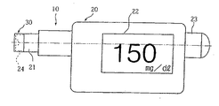
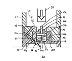
以下、本願発明の好ましい実施の形態を図面を参照しつつ、説明する。図1は、本願発明に係る体液測定装置の全体外観図、図2、図3は、装着体の詳細を示す拡大縦断面図、図4は、センサ構成部分の平面図、図5は、センサを完成させた状態の縦断面図である。
【0031】
図1ないし図3に示されるように、本願発明に係る体液測定装置10は、本体20と装着体30とを組み合わせて使用される。本体20は、その上面にスイッチボタン類、LCD表示器22などが配置されている。この本体20の前部には筒状部21が延出形成されており、その先端部には、後に詳しく説明するキャップ状の装着体30が装着されている。また、この本体20の内部には、装着体30が備える穿刺体31を前進駆動するための駆動機構(23,32)、および、マイクロコンピュータ等の回路等が内蔵される。図1において符号23は、上記駆動機構の一部を構成し、使用者が手動によって押圧するための押圧部を示している。
【0032】
図2および図3に装着体30の一例の詳細を示す。この装着体30は、円筒部34と、この円筒部34の先端を塞ぐように位置する底壁部35とを備える大略キャップ状をしており、その主要部分は樹脂成形によって作製される。円筒部34の内径は、本体20の前部筒状部24の外径と対応させられており、この前部筒状部24に被せるようにして簡便に装着することができる。
【0033】
このキャップ状の装着体30の底壁部35には、穿刺体31と、バイオセンサ36とが一体に組み込まれる。底壁部35には、円筒壁35bと底壁35cとを有する円筒状の陥没部35Aがこの装着体30の中心位置に形成され、この陥没部35Aの底壁35cには、中心孔35dが開けられている。
【0034】
一方、穿刺体31は、上記中心孔35dにスライド可能に嵌合するガイド軸部31aとこのガイド軸部31aの一端に一体形成されたフランジ部31bとを有する樹脂製のガイド体31Aに金属製の穿刺針31cを一体にインサートした形態をもっており、フランジ部31bと後述する板状バイオセンサ36の上面との間に介装された弾性体31dにより、常時図2に示す退避位置、すなわち、フランジ部31bが陥没部35Aの底壁35cに当接する位置に向けて付勢されている。この退避位置において、ガイド軸部31aの後端は底壁35cの内側に突出した状態となり、穿刺針31cは、後述する板状バイオセンサ36の裏側に退避した状態となる。上記のように穿刺体31を退避位置に向けて付勢する弾性体31dの態様としては、図2および図3に示されるように金属あるいは樹脂でできた圧縮コイルバネを用いるほか、発泡ウレタン等の形態とすることができる。このように弾性体31d を発泡ウレタンの形態とし、穿刺体31が退避位置をとるとき穿刺針31cがこの発泡ウレタンの内部に埋没するようにしておくと、この穿刺針が外物に触れる機会を少なくすることができるので、衛生的である。また、上記弾性体31d は、樹脂製のガイド体31Aと一体成形された板状バネの形態とすることができる。
【0035】
図2に示す実施の態様においては、板状バイオセンサ36は皮膚当接部37のみを介して皮膚40に接することができるように、皮膚40に対して角度をもって配置される。また、皮膚当接部37は穿刺体31の進出位置、すなわち穿刺箇所の近傍へ配置される。
【0036】
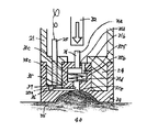
図3に示す実施の態様においては、板状バイオセンサ36は皮膚当接部37のみを介して皮膚40に接することができるように、皮膚40に負圧を作用させるための開口35e近傍に配置される。また、皮膚当接部37は穿刺体31の進出位置、すなわち穿刺箇所の近傍へ配置される。尚、図中点線で示される貫通孔35fは皮膚へ負圧を作用させるためのものである。
【0037】
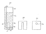
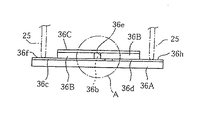
板状バイオセンサ36は、上面に作用極36cおよび対極36dが膜形成された絶縁ベース板36Aと、作用極36cおよび対極36dの一部を露出させる溝36eを形成するように絶縁ベース板36A上に積層された板状スペーサ36B,36Bと、この板状スペーサ36B,36Bにさらに積層された板状カバー36Cとを備えている。以下、この板状バイオセンサ36の作製工程を説明する。
【0038】
図4に示すように、たとえば0.2mmの厚みをもつ樹脂製絶縁シートからなる平面視長矩形状のベース板36Aが準備される。このベース板36Aの上面には、グラファイトインクを用いたスクリーン印刷の手法により、作用極36cと対極36dとが膜状に形成される。作用極36cは、端子部となるべき端部領域36fから電極として機能する領域36gが延出形成された平面形態をもち、一方、対極36dは、端子部となるべき端部領域36hから電極として機能する領域36iをもつ平面形態をもっている。なお、上記作用極36cおよび対極36dは、金や白金などの貴金属を蒸着するとともにエッチング処理して所定のパターンを作ることによって形成することもできる。
【0039】
次に、作用極36cおよび対極36dの各突出部36g,36iが縦方向に並ぶ帯状領域と、作用極36cおよび対極36dの各端部領域36f,36hを残してレジスト層36jを印刷形成する。
【0040】
続いて、上記レジスト層36jに重ねるようにして、レジスト層36jと同等の平面形状を有するスペーサ板36Bを配置する。このスペーサ板36Bとしては、たとえば厚み0.2mmの樹脂製の板が採用され、表裏面に粘着剤層を設けた両面テープ態様のものが使用される。これにより、スペーサ板36Bで挟まれる凹溝36eが形成され(図5参照)、かつこの凹溝36eの底部の帯状の領域に上記作用極36cと対極36dの各突出部36g,36iが並んで露出する格好となる。なお、上記凹溝36eの幅は、たとえば1.5mm、長さはたとえば3mmに設定される。
【0041】
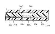
次に、上記凹溝36eの底部の帯状の領域に、図5に良く表れているような反応試薬層36kを形成する。血糖値測定用のセンサとして構成する場合、この反応試薬は、酸化酵素であるグルコースオキシターゼおよびメディエータとしてのフェリシアン化カリウムを含むものが採用される。反応試薬層36kはたとえば分注法により形成される。
【0042】
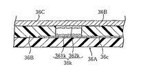
次に、図5に示したようにスペーサ板36Bに重ねるようにして、貫通孔36mを有する平面視矩形状のカバー板36Cを重ね合わせてこのバイオセンサ36が完成する。すなわち、図5に表れているように、上記ベース板36Aとスペーサ板36B,36Bとで形成された凹溝36eをカバー板36Cで塞ぐことによって縦方向に延びる断面横長矩形状の体液通路36bが形成され、かつ、この体液通路36bの内面に、作用極36cおよび対極36dに接触する試薬層36k(反応部)が形成される。この体液通路36bの容積は、前述した凹溝36eの幅、長さ、およびスペーサ板36B,36Bの厚み寸法から、1.5mm×3mm×0.2mm=0.9μlとなるが、試薬層36kの固形分体積約0.2μlを差し引くと、この体液通路36bの実質容積は約0.7 μlというきわめて小さなものとなる。
【0043】
板状バイオセンサ36のベース板36Aの端部に露出する作用極36cおよび対極36d用の端子部36f,36hと本体20は、コネクタピン25 aの先端を上記端子部36f,36hに接触させることによって電気的に接続される。
【0044】
一方、本体20の筒状部21には、コネクタピン25 aの先端がこの筒状部21の前面に弾性的に突出するようにして、一対のピンコネクタ25が組み込まれている。このピンコネクタ25は、図8に示したように電子回路33に接続されている。この電子回路33は、マイクロコンピュータなどで構成され、後述するようにバイオセンサ36内で生じる酵素反応および電気化学反応によって生じる作用電流から検量線を用いて血糖値等の被検知物質の測定値を決定するとともに、これを本体20の表面に配した表示器22に表示する機能をもたせてある。さらに、本体20には、図2および図3に示したように上記押圧部23によって押圧駆動される押圧ロッド32がその軸線方向(図中に矢印で示した方向)に移動可能であり、かつバネによって常時後方側に付勢されながら組み込まれて駆動機構23,32が構成されている。なお、駆動機構23,32としては、これに限らず、軸方向移動可能であってしかも軸方向の中立位置に弾性復帰するように押圧ロッド32を設け、この押圧ロッド32を後方に引き絞ってラッチ保持し、ラッチ解除ボタンを押すことでこの押圧ロッド32を勢い良く前方発射させ、この押圧ロッド32が穿刺体31のガイド軸部31aの後端を勢いよく打ちつけ、これにともなって穿刺針31cが瞬間的に皮膚当接面35aから突出するように構成することも可能である。また、図示しない吸引シリンダ機構を本体20に内蔵させることにより、筒状部21の先端に負圧を作用させることができるようにすることもできる。また、装着体30を本体20に装着したときにバイオセンサ36の端子部と導通接触するべく本体20に設ける端子は、前述したように常時ピンが弾性的に突出するピンコネクタの形態とするほか、たとえば、装着体30の本体20への装着と連動して、装着体30が装着されていないときには端子ピンが本体内に退動しており、装着体30が装着されると端子ピンが本体から突出してバイオセンサの端子部との適切な導通接触が図られるように構成することも可能である。
【0045】
次に、上記構成を備える体液測定装置10の使用方法ないし動作を図1ないし図3を参照しつつ説明する。
【0046】
装着体30は、使い捨て消耗品として提供され、体液測定装置10の使用にあたって使用者はこの装着体30を本体20の筒状部21に装着する(図1参照)。上記実施形態において装着体30はキャップ状をしているので、このような装着作業は容易に行える。装着体30が装着されると、図2に表れているように本体側のコネクタピン25 aの先端がバイオセンサ36のベース板36A両端上面に配置された電極部36f,36hに自動的に接触する。
【0047】
装着体30の底壁部35の端面 35 ′、およびバイオセンサ 36 の皮膚当接部 37を患者の皮膚の適当な部位、たとえば指先や耳たぶに押し当てた状態で、押圧部23を押下する。そうすると、本体20の内部の押圧ロッド32の先端が穿刺体31のガイド軸部31aの後端部を押し、押圧ロッド32が装着体30の陥没部35Aの裏側に当接するまでのストロークをもって穿刺体31を弾性体37の弾力に抗して前方に押し出す。このとき、穿刺体31の穿刺針31cは、バイオセンサ36の皮膚当接部37の近傍を穿刺して皮膚に傷を付け、血液を出液させる。押圧部23への押圧を解除すると、押圧ロッド32はバネの弾力によって元の位置まで復帰動し、また、穿刺体31もまた弾性体37の弾力によって穿刺針31cが皮膚当接部37から没入する退避位置まで復帰する。
【0048】
穿刺針31cの突出により、皮膚に適度な傷がつけられ、この傷から出液した血液が、毛管現象により、皮膚当接部37を介してバイオセンサ36内の体液通路36bに導入させられる。皮膚当接部37は穿刺針31c進出位置、つまり皮膚の傷、したがって出液部にきわめて近傍に位置している。そうして、前述したように、バイオセンサ36内の体液通路36bの実質容積はきわめて小さいため、少量の血液で体液通路36bを充満させることが可能である。したがって、出液部の血液量をいちいち黙視確認するまでもなく、皮膚当接部37を皮膚に押し付けたまま上記の操作をし、かつ皮膚当接部37を皮膚に押し付けた状態を所定時間保持するだけで、測定に必要十分な血液をセンサ中の体液通路36bに導入することができる。なお、前述したように、吸引シリンダ機構を本体に付加し、開口35e(および貫通孔35f)を介して皮膚に負圧を作用させながら上述した操作をすると、鬱血状態の皮膚に穿刺針31cで傷を付けることができるため、より充分な量の血液を出液させることができる。
【0049】
バイオセンサ36内の体液通路36b内において、反応試薬(反応部36k)が血液によって溶解されると、以下の数3に示される酵素反応が開始される結果、反応部36kに共存させているフェリシアン化カリウムが還元され、還元型の電子伝達体であるフェロシアン化カリウムが蓄積される。
【0050】
【数3】
フェロシアン化カリウムの蓄積量は、基質濃度、すなわち血液中のグルコース濃度に比例する。一定時間蓄積された還元型の電子伝達体は、以下の数4に示される電気化学反応により、酸化される。
【0052】
【数4】
測定装置本体20 の内の電子回路33は、このとき測定される作用極電流から、グルコース濃度(血糖値)を演算・決定し、好ましくはたとえば本体20 の表面に配置されたLCD表示器22に表示する。
【0054】
このように、上記体液測定装置10によれば、装着体30を本体20の所定部位に装着するという簡単な前準備をした後、装着体30の端面 35 ′およびバイオセンサ 36の皮膚当接部 37を患者の指先や耳たぶ等に押し当てた状態を保持しつつ、あたかも従来のランセットを扱うようにして穿刺針31cを突出させるという操作をするだけで、それ以上の操作、あるいは動作を要することなく、血糖値等の体液測定を適正に行うことができる。
【0055】
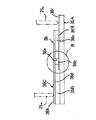
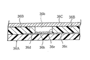
図6ないし図11は、バイオセンサ36の他の構造例を示す。このバイオセンサ36は、ベース板36Aと、スペーサ板36B,36Bと、カバー板36Cとを備える点では前述のバイオセンサ36と同様であるが、ベース板36Aには作用極36cのみが形成され、カバー板36Cとして導電性金属を用いることにより、このカバー板36Cの内面を対極36dとして機能させている。より具体的には、ベース板36Aには、図4に示すようなパターンの作用極36cが形成される。そして、図10および図11に示すように、この作用極36cの内方の一部を露出させるようにして、所定の間隔をあけて2枚のスペーサ板36B,36Bが重ねられる。これにより、作用極36cの一部が底面に露出する凹溝36eが形成される。作用極36cの外方部は露出させられ、コネクタピン25a,25aと接触する電極部36fとして機能する。凹溝36eの幅、長さ、深さは、それぞれ、前述の実施形態のものと同等に設定され、この凹溝36eとカバー体36Cとにより、体液通路36bが形成される。凹溝36eの底部には、反応試薬が塗布された反応部36kが形成される。このセンサ36を血糖値測定用に構成する場合、反応試薬として、前述したのと同様のものを用いることができる。カバー体36Cの上面適部は、コネクタピン25aと接触する電極部36hとして機能させられる。
【0056】
なお、図6ないし図11の構造のバイオセンサ36において、図 に示したようにベース板36Aに形成する作用極36cに接触するようにしてフェリシアン化カリウムを含む反応試薬層361k(第1反応部)を形成する一方、カバー体36Cの内面に酸化酵素であるグルコースオキシターゼおよびメディエータとしてのフェリシアン化カリウムを含む反応試薬層362k(第2反応部)を形成することによって反応部36kを形成する態様とすることも可能である。このようにすれば、酵素反応および電気化学反応を介して作用極電流を検出するこの種のバイオセンサ36において、アスコルビン酸の影響を除去したより正確な測定が可能となる。
【0057】
もちろん、この発明の範囲は上述した実施形態に限定されることはない。実施形態では、血糖値を測定するためのものとして説明されているが、測定対象は血糖値に限定されない。また、装着体の具体的形状およびバイオセンサの具体的構造は、種々変更可能である。本願発明の最も重要なポイントは、本体に装着して使用される好ましくは使い捨ての装着体に穿刺体とバイオセンサとが一体的に組み込まれている点である。また、更に重要なポイントは、バイオセンサが皮膚当接部のみを介して皮膚と接している点である。
【図面の簡単な説明】
【図1】 本発明に係る体液測定装置の全体外観図である。
【図2】 装着体の詳細を示す拡大縦断面図である。
【図3】 他の態様の装着体の詳細を示す拡大縦断面図である。
【図4】 センサを分解した状態の平面図である。
【図5】 センサの縦断面図である。
【図6】 センサの縦断面図である。
【図7】 センサの縦断面図である。
【図8】 電気的な構成を説明するための概略構成図である。
【図9】 センサの縦断面図である。
【図10】 センサの縦断面図である。
【図11】 センサの縦断面図である。
【符号の説明】
10 体液測定装置
20 本体
23 押圧部(駆動機構を構成する)
25a コネクタピン(本体の端子としての)
30 装着体
31 穿刺体
31d 弾性体
32 押圧ロッド(駆動機構を構成する)
33 電子回路
36 センサ
36A ベース板(センサを構成する)
36B スペーサ(センサを構成する)
36C カバー板(センサを構成する)
36b 体液流路(センサの)
36c 作用極(センサの)
36d 対極(センサの)
36e 溝(センサの)
36k 反応部(センサの反応試薬層)
36f,36h 端子部(センサの電極としての)
361k 第1反応部(センサの反応試薬層)
362k 第2反応部(センサの反応試薬層)
37 皮膚当接部(センサの(体液吸引口)) [0001]
BACKGROUND OF THE INVENTION
The present invention can measure a substance to be detected contained in a body fluid such as blood glucose concentration (hereinafter referred to as “blood glucose level”), and collects and measures body fluid from the skin by an integrated operation. The present invention relates to a lancet-integrated bodily fluid measuring device configured to be able to perform such operations.
[0002]
BACKGROUND OF THE INVENTION
In order to treat diabetes, it is necessary to keep the blood glucose level of the patient in a normal range, and blood glucose level management by the patient himself is an important treatment method. In particular, when the blood glucose level is maintained in a normal range by insulin injection by the patient himself, appropriate blood glucose level measurement by the patient himself is indispensable.
[0003]
Portable blood glucose level measuring devices used for such a purpose are already on the market, and an example thereof is disclosed in, for example, Japanese Patent Publication No. 8-20412. This blood glucose level measuring apparatus is used by inserting a disposable test piece having an enzyme electrode into a main body. When blood as a specimen is brought into contact with the test piece, a part of the blood is drawn into the reaction part by capillary action, and an anodic current is generated through an enzyme reaction and an electrochemical reaction. This anode current is converted into a blood glucose level in the apparatus body and displayed.
[0004]
By the way, a sample to be brought into contact with a test piece of the measuring apparatus as described above, that is, blood is generally collected using an instrument called a lancet as disclosed in, for example, Japanese Patent Laid-Open No. 9-266898. It is. This lancet is a device for making a small hole (scratching) in the skin of a patient's fingertip, etc., and letting the blood discharged from the hole thus opened touch a predetermined part of the above-mentioned test piece Therefore, the blood glucose level can be measured relatively easily.
[0005]
However, in the conventional general blood sugar level self-measuring method described above, since the lancet for collecting blood as a sample and the measuring device are separate, the lancet is combined with the inconvenience of having to carry both. Therefore, it is necessary to perform two operations, that is, the operation of scratching the skin and the operation of causing blood drawn from the wound to touch the test piece, and there is still room for improvement in terms of convenience. In particular, with regard to the action of touching the test piece with blood, it is necessary to bring the required amount of blood into contact with the specified part of the test piece, and this is done for patients who are unfamiliar or who have poor vision. Alternatively, when blood is collected from an earlobe that is not directly visible to the person, it is extremely difficult to quickly and appropriately touch the blood drawn from the wound as described above.
[0006]
In addition, since the test piece is configured to draw blood by capillary action from a hole at the tip to a planar enzyme electrode provided in the reaction part, in order to allow a necessary amount of blood to reach the reaction part, 3 to 5 μl of blood needs to touch the specimen. If this amount of blood is insufficient, or if this amount of blood is not properly attached to a small area surrounding the tip hole of the test piece, accurate measurement may not be possible. Such a situation can occur frequently when the amount of blood discharged from a wound is insufficient, such as an infant or an elderly person.
[0007]
In order to solve the above problems, Japanese Patent Laid-Open No. 10-28683 discloses that a sensor incorporated in a device is simply skinned with a lancet incorporated in the device. There has been proposed a lancet-integrated blood glucose level measuring device that measures blood discharged from the lancet. However, in the device disclosed in the publication, the lancet needle and the sensor have to be set separately at predetermined positions in the apparatus, and there is still room for improvement in terms of usability.
[0008]
In order to improve usability, a lancet-integrated body fluid measuring device that uses a lancet and a sensor integrally is disclosed in Japanese Patent Application No. 10-166894. This lancet-integrated body fluid measuring device has the following configuration. That is, a body fluid measuring device including a main body and a mounting body mounted on the main body for use, wherein the mounting body includes a skin contact surface and a sensor disposed along the skin contact surface. A puncture body that is movable between an advancing position in which the tip protrudes from the skin contact surface and a retracted position in which the tip is recessed from the skin contact surface and is biased toward the retracted position by an elastic body; The main body has a terminal that contacts each electrode of the sensor included in the mounting body when the mounting body is mounted and conducts to the electrode, and is measured based on an electrical signal obtained through the terminal. An electronic circuit for determining a value and a drive mechanism for driving the puncture body forward so that the puncture body takes an advanced position are provided. Further, the sensor in the wearing body has a plate shape extending along the skin contact surface as a whole, and a body fluid passage is formed inside the thickness direction so that the reaction portion faces the inner surface, and In addition, there is provided a configuration in which a through hole is formed which communicates with the body fluid passage and allows the tip of the puncture body to pass therethrough.
[0009]
Since the through-hole through which the puncture body passes and the body fluid passage in the sensor communicate with each other, blood discharged from the wound on the skin directly enters the through-hole, and subsequently fills the body fluid passage where the reaction part faces. It is done. Therefore, the distance from the skin wound to the reaction part is remarkably shortened. Further, since the sensor itself has a plate shape, the volume of the body fluid passage can be reduced. For this reason, the blood volume required for measurement can be significantly reduced.
[0010]
However, in the bodily fluid measuring device described in Japanese Patent Application No. 10-166894, the plate-like sensor of the mounting body used by being mounted on the bodily fluid measuring device is arranged substantially in parallel with the skin and serves as a blood introduction port. Since the sensor and the skin are in contact with the part other than the through hole, the blood discharged from the wound on the skin directly enters the through hole, and the contact part between the sensor and the sensor other than the through hole and the skin There was a problem that it entered into the gap that could be made between. In this case, the discharged blood does not reach the reaction part inside the sensor, and measurement is impossible. That is, blood collection for measurement fails. Therefore, the user has to redo the measurement. By doing so, the user suffers from the pain of being forced to puncture twice or more in one measurement, and also suffers from the pain that the skin is contaminated with blood. In addition, it is necessary to use two or more attachments for one measurement, which is a problem from the viewpoint of cost.
[0011]
The essence of the above problem from the technical aspect is that the flow path of the discharged blood exists other than the blood inlet of the sensor. That is, the discharged blood is guided to the body fluid passage of the sensor as a capillary phenomenon from the body fluid introduction port, but since there is a contact point between the sensor and the skin other than the body fluid introduction port, the blood is interposed between the sensor and the skin. There is room to enter the gaps that can be created as capillary action. This is because the gap formed between the sensor and the skin is usually narrow enough to cause capillary action, that is, the surface area per volume is sufficiently large. In other words, the capillary phenomenon to the blood inlet and the capillary phenomenon to the other are competing.
[0012]
The invention of the present application has been conceived under such circumstances, and it is possible to further improve the usability by further simplifying the operation required of the patient for measurement and to significantly increase the necessary sample amount. An object of the present invention is to provide a lancet-integrated bodily fluid measuring device that can reduce blood pressure and reliably collect blood and can improve measurement reliability.
[0013]
DISCLOSURE OF THE INVENTION
In order to solve the above problems, the present invention takes the following technical means.
[0014]
The body fluid measuring device provided by the present invention is:A body fluid measuring device comprising a main body and a mounting body to be used by being mounted on the main body, wherein the main body contacts each electrode of a sensor included in the mounting body when the mounting body is mounted. And an electronic circuit for determining a measurement value based on an electric signal obtained through the terminal, and a drive mechanism for driving the puncture body forward so that the puncture body takes an advanced position. The wearable body is a puncture that is movable between a sensor having a skin contact portion and a position where the tip protrudes to the vicinity of the skin contact portion and a retreat position where the tip is recessed from the skin contact portion. BACKGROUND OF THE INVENTION 1. Field of the Invention The present invention relates to a body fluid measuring device including a body and a mounting body in such a body fluid measuring device, and the gist thereof is to bring a sensor into contact with the skin only through the skin contact portion. By arranging the sensor in this way, there is no room for blood to enter between the skin and the portion other than the skin contact portion, and the flow path of the discharged blood is limited to the body fluid passage of the sensor. Can do.
[0015]
The wearing body is provided as a disposable consumable, for example. In the measurement, the user wears the wearing body on the main body. Operate the drive mechanism of the main unit while pressing the skin contact part against the skin of the fingertip or earlobe.SetThen, the puncture body in the retracted position is advanced, and the tip of the puncture body protrudes from the skin contact surface, thereby damaging the skin. The puncture body returns to the retracted position by the action of the next instantaneous elastic body. If the apparatus is kept as it is, blood discharged from the skin permeates the sensor, and the sensor outputs a reaction current. This electric current is converted into a specific component concentration in the blood by an electronic circuit and displayed on, for example, a display arranged on the surface of the main body.
[0016]
Thus, in the body fluid measurement device of the present invention, since the puncture body and the sensor are integrated in advance in the mounting body, the user only needs to mount the mounting body on the main body for measurement. Compared with the case where the measuring device and the measuring device are used separately, as compared with the conventional lancet-integrated blood measuring device in which the lancet needle and the sensor need to be set separately at a predetermined part of the device, Its usability is significantly improved.
[0017]
The skin contact portion of the sensor incorporated in the wearing body simultaneously constitutes a body fluid suction port. And the skin contact part is arrange | positioned so that it may become the advance position of the puncture body. The vicinity mentioned here refers to a degree of proximity so that blood discharged from the puncture body injuries the skin immediately contacts the body fluid suction port when blood drops are formed. For example, if the blood required for measurement is 1 μl, (1μ lThe body fluid suction port needs to be arranged at least within 1 mm from the advancement position of the puncture body.
[0018]
As a means for arranging the sensor so as to come into contact with the skin only through the skin contact portion, the sensor is preferably arranged at an angle of 5 to 90 degrees with respect to the skin. By doing so, the part other than the skin contact part is detached from the skin, and blood can be prevented from entering the gap formed between the skin and the part other than the skin contact part. If the angle between the sensor and the skin is 5 degrees or less, the gap between the skin and the portion other than the skin contact portion is not sufficient, and blood may enter the gap, which is not preferable. Even if the angle between the sensor and the skin is 90 degrees or more, if the angle from the opposite direction is measured, it is less than 90 degrees, and there is no difference from the case where the angle is less than 90 degrees.
[0019]
As another means for arranging the sensor so as to be in contact with the skin only through the skin contact portion, the skin contact portion is arranged in the vicinity of the advancement position of the puncture body and in the vicinity of the opening for applying negative pressure to the skin. It is. The skin swells by applying a negative pressure, and becomes a protrusion near the opening. By disposing the skin contact portion of the sensor so as to be in contact with the protruding skin, the sensor can be disposed so as to be in contact with the skin only through the skin contact portion. That is, a negative pressure is applied to the skin that is essentially flat to give a three-dimensional shape (protrusion), and contact with the skin only through the skin contact portion without taking measures such as tilting the sensor. It is arranged. Even in this case, the portion other than the skin contact portion is detached from the skin, and blood can be prevented from entering the gap formed between the skin and the portion other than the skin contact portion.
[0020]
In a preferred embodiment, the wearing body has an opening for applying a negative pressure to the skin. If comprised in this way, since the skin surface can be congested and can be injured by the puncture body, a sufficient amount of blood can be discharged, and the measurement can be made more reliable.
[0021]
In a preferred embodiment, the sensor in the mounting body further includes a base plate having a working electrode and a counter electrode formed on an upper surface, and a groove formed so as to face a part of each of the working electrode and the counter electrode. The spacer includes a spacer superimposed on the base plate, a reaction part in which a reaction reagent layer is formed on a part or all of the groove, and a cover plate superimposed on the spacer. A space surrounded by the plate forms a body fluid passage, and a terminal portion that is electrically connected to the working electrode and the counter electrode and is brought into contact with the terminal of the main body is disposed at an appropriate upper surface of the base plate.
[0022]
In another preferred embodiment, the sensor in the mounting body includes a base plate having a working electrode formed on an upper surface thereof, and a groove on the base plate so that a part of the working electrode is faced to form a groove. A first electrode layer formed on the groove so as to be in contact with the working electrode, and a spacer plate overlaid on the spacer and having a counter electrode facing the groove on the lower surface. A reaction part and a second reaction part having a second reagent layer formed on the lower surface of the cover plate so as to be in contact with the counter electrode, and a space surrounded by the groove and the cover plate is formed. While the body fluid passage is formed, the first terminal portion that is electrically connected to the working electrode and is brought into contact with the terminal of the main body is disposed at an appropriate portion of the upper surface of the base plate, and is electrically connected to the counter electrode. 2nd terminal part made to contact with the terminal of It is disposed on the upper surface of the cover plate.
[0023]
With this configuration, the base plate is printed by, for example, screen printing.PoleAlternatively, a counter electrode can be easily formed, and a plate sensor in which a body fluid passage is properly formed in the thickness direction can be easily manufactured by a simple method of stacking plate components.
[0024]
When the body fluid measuring device of the present invention is configured for blood glucose level measurement, for example, a reagent containing glucose oxidase as an oxidase and potassium ferricyanide as a mediator is employed as a reaction reagent disposed in the reaction part of the sensor. The
[0025]
When the reaction part is dissolved by blood, the enzyme reaction shown in Equation 1 is started, and as a result, potassium ferricyanide coexisting in the reaction layer is reduced, and reduced type electron carrier potassium ferrocyanide is accumulated. The The amount is proportional to the substrate concentration, ie the glucose concentration in the blood. The reduced electron carrier accumulated for a certain period of time is oxidized by an electrochemical reaction expressed by Equation 2. The electronic circuit in the measuring apparatus main body calculates and determines the glucose concentration (blood glucose level) from the anode current measured at this time, and displays it on the display device arranged on the main body surface as described above.
[0026]
[Expression 1]
[Expression 2]
Thus, according to the bodily fluid measurement device according to the present invention, after the mounting body provided for disposable use is mounted on the main body, the skin contact portion of this mounting body is pressed against the patient's fingertip or earlobe. It is possible to properly measure body fluids such as blood sugar level without requiring any further operation or operation, just by operating the lancet as if handling a conventional lancet it can. In addition, since the amount of specimen required for measurement is small, the burden on the patient is reduced. In addition, it is possible to reliably perform measurement with one puncture without failing to collect blood and making measurement impossible.
[0029]
Other features and advantages of the present invention will become apparent from the detailed description given below with reference to the drawings.
[0030]
DETAILED DESCRIPTION OF THE INVENTION
Hereinafter, preferred embodiments of the present invention will be described with reference to the drawings. FIG. 1 is an overall external view of a body fluid measuring device according to the present invention, FIGS. 2 and 3 are enlarged longitudinal sectional views showing details of a mounted body, FIG. 4 is a plan view of sensor components, and FIG. It is a longitudinal cross-sectional view of the state which completed.
[0031]
As shown in FIGS. 1 to 3, the body
[0032]
2 and 3 show details of an example of the mounting
[0033]
The
[0034]
On the other hand, the
[0035]
In the embodiment shown in FIG. 2, the plate-
[0036]
In the embodiment shown in FIG. 3, the plate-
[0037]
The plate-
[0038]
As shown in FIG. 4, a
[0039]
Next, a resist layer 36j is formed by printing while leaving the band-like regions in which the projecting portions 36g and 36i of the working
[0040]
Subsequently, a
[0041]
Next, a
[0042]
Next, as shown in FIG. 5, the
[0043]
The
[0044]
On the other hand, the
[0045]
Next, a usage method or operation of the body
[0046]
The mounting
[0047]
Of the
[0048]
Due to the protrusion of the
[0049]
In the
[0050]
[Equation 3]
The accumulated amount of potassium ferrocyanide is proportional to the substrate concentration, that is, the glucose concentration in blood. The reduced electron carrier accumulated for a certain period of time is oxidized by the electrochemical reaction shown in the following Equation 4.
[0052]
[Expression 4]
Measuring device body20 ofInside electronic circuit33Calculates and determines the glucose concentration (blood glucose level) from the working electrode current measured at this time.20
[0054]
As described above, according to the body
[0055]
6 to 11 show other structural examples of the
[0056]
In the
[0057]
Of course, the scope of the present invention is not limited to the embodiment described above. In the embodiment, the blood glucose level is described as being measured, but the measurement target is not limited to the blood glucose level. The specific shape of the wearing body and the specific structure of the biosensor can be variously changed. The most important point of the present invention is that the puncture body and the biosensor are integrally incorporated in a preferably disposable mounting body that is used by being mounted on the main body. A more important point is that the biosensor is in contact with the skin only through the skin contact portion.
[Brief description of the drawings]
FIG. 1 is an overall external view of a body fluid measuring device according to the present invention.
FIG. 2 is an enlarged longitudinal sectional view showing details of the mounting body.
FIG. 3 is an enlarged longitudinal sectional view showing details of a mounting body according to another embodiment.
[Figure 4] SensorDisassembled stateFIG.
FIG. 5 is a longitudinal sectional view of a sensor.
FIG. 6 is a longitudinal sectional view of a sensor.
FIG. 7 is a longitudinal sectional view of a sensor.
FIG. 8 is a schematic configuration diagram for explaining an electrical configuration;
FIG. 9 is a longitudinal sectional view of a sensor.
FIG. 10 is a longitudinal sectional view of a sensor.
FIG. 11 is a longitudinal sectional view of a sensor.
[Explanation of symbols]
10 Body fluid measuring device
20 body
23 Pressing part (constituting drive mechanism)
25a Connector pin (as terminal of main body)
30 Wearing body
31 Puncture body
31d elastic body
32 Press rod (constitutes drive mechanism)
33 Electronic circuit
36 sensors
36A Base plate (constituting sensor)
36B Spacer (constituting sensor)
36C Cover plate (constituting sensor)
36b Body fluid flow path (for sensor)
36c Working electrode (sensor)
36d Counter electrode (sensor)
36e Groove (sensor)
36k reaction part (reaction reagent layer of sensor)
36f, 36h terminal part (as sensor electrode)
361k 1st reaction part (reaction reagent layer of sensor)
362k 2nd reaction part (reaction reagent layer of sensor)
37 Skin contact part(Sensor (Body fluid suction port))
Claims (10)
上記本体は、上記装着体が装着されたときにこの装着体が備えるセンサの各電極に接触してこれらに導通する端子、この端子を介して得られる電気信号に基づいて測定値を決定する電子回路、および、上記穿刺体を前進駆動してこの穿刺体に進出位置をとらせるための駆動機構を備えており、
上記装着体は、皮膚当接部を有するセンサと、尖端が皮膚当接部近傍へ突出する進出位置と尖端が皮膚当接部から没入する退避位置との間を移動可能である穿刺体とを備えており、
上記センサは、全体として板状を呈しているとともに、その厚み方向の内部に内面に反応部が臨む体液通路が形成されており、かつ、上記皮膚当接部のみを介して皮膚に接触し、かつ皮膚における上記皮膚当接部との接触部分での接線方向に対して5〜90度の角度をもって配置されており、
上記センサはさらに、作用極が上面に形成されたベース板と、上記作用極の一部を臨ませて溝を形成するように上記ベース板上に重ね合わされたスペーサと、上記スペーサに重ね合わされ、下面に上記溝に臨む対極が形成されたカバー板と、上記作用極に接触するように上記溝に第1の試薬層を形成した第1の反応部と、上記対極に接触するように上記カバー板の下面に第2の試薬層を形成した第2の反応部とを備えて形成されており、上記溝とカバー板とで囲まれる空間が体液通路を形成している一方、上記作用極と導通して本体の端子と接触させられる第1の端子部が上記ベース板の上面適部に配置されているとともに、上記対極と導通して本体の端子と接触させられる第2の端子部が上記カバー板の上面に配置されており、
上記皮膚当接部は、上記体液通路に連通する体液吸引口を構成するとともに上記穿刺体の尖端の進出位置近傍に配置されていることを特徴とする、体液測定装置。A body fluid measuring device comprising a main body and a mounting body to be used by mounting on the main body,
The main body is a terminal that contacts each electrode of the sensor included in the mounting body when the mounting body is mounted and conducts to the electrodes, and an electronic that determines a measured value based on an electrical signal obtained through the terminal. A circuit, and a drive mechanism for driving the puncture body forward so that the puncture body takes an advanced position,
The mounting body includes a sensor having a skin contact portion, and a puncture body that is movable between an advancing position in which the tip protrudes in the vicinity of the skin contact portion and a retracted position in which the tip is recessed from the skin contact portion. Has
The sensor has a plate-like shape as a whole, and a body fluid passage is formed on the inner surface in the thickness direction so that the reaction portion faces the inner surface, and contacts the skin only through the skin contact portion. And it is arranged at an angle of 5 to 90 degrees with respect to the tangential direction at the contact portion of the skin with the skin contact portion,
The sensor further includes a base plate having a working electrode formed on an upper surface thereof, a spacer superimposed on the base plate so as to form a groove so as to face a part of the working electrode, and the spacer. A cover plate having a counter electrode facing the groove formed on a lower surface; a first reaction part having a first reagent layer formed in the groove so as to contact the working electrode; and the cover so as to contact the counter electrode A second reaction portion having a second reagent layer formed on the lower surface of the plate, and a space surrounded by the groove and the cover plate forms a body fluid passage, A first terminal portion that is electrically connected and brought into contact with a terminal of the main body is disposed on an appropriate portion of the upper surface of the base plate, and a second terminal portion that is electrically connected to the counter electrode and brought into contact with the terminal of the main body is It is arranged on the upper surface of the cover plate,
The bodily fluid measuring device, wherein the skin contact portion constitutes a bodily fluid suction port communicating with the bodily fluid passage and is disposed in the vicinity of the advance position of the tip of the puncture body.
上記本体は、上記装着体が装着されたときにこの装着体が備えるセンサの各電極に接触してこれらに導通する端子、この端子を介して得られる電気信号に基づいて測定値を決定する電子回路、および、上記穿刺体を前進駆動してこの穿刺体に進出位置をとらせるための駆動機構を備えており、 上記装着体は、皮膚当接部を有するセンサと、尖端が皮膚当接部近傍へ突出する進出位置と尖端が皮膚当接部から没入する退避位置との間を移動可能である穿刺体とを備えており、
上記センサは、上記皮膚当接部のみを介して皮膚に接触し、かつ皮膚における上記皮膚当接部との接触部分での接線方向に対して5〜90度の角度をもって配置されており、
上記本体における端子は、その先端が本体から突出する進出位置と、この進出位置より後退する後退位置との間を移動可能であり、かつ、常時バネによって進出方向に付勢されていることを特徴とする、体液測定装置。A body fluid measuring device comprising a main body and a mounting body to be used by mounting on the main body,
The main body is a terminal that contacts each electrode of the sensor included in the mounting body when the mounting body is mounted and conducts to the electrodes, and an electronic that determines a measured value based on an electrical signal obtained through the terminal. A circuit and a drive mechanism for driving the puncture body forward so that the puncture body takes an advanced position, and the mounting body includes a sensor having a skin contact portion, and a tip having a skin contact portion. A puncture body that is movable between an advancing position that protrudes in the vicinity and a retreat position in which the tip is retracted from the skin contact portion;
The sensor is disposed at an angle of 5 to 90 degrees with respect to the skin through only the skin contact portion, and with respect to the tangential direction at the contact portion of the skin with the skin contact portion,
The terminal in the main body is movable between an advanced position where the tip protrudes from the main body and a retracted position retracted from the advanced position, and is always biased in the advanced direction by a spring. A body fluid measuring device.
上記本体は、上記装着体が装着されたときにこの装着体が備えるセンサの各電極に接触してこれらに導通する端子、この端子を介して得られる電気信号に基づいて測定値を決定する電子回路、および、上記穿刺体を前進駆動してこの穿刺体に進出位置をとらせるための駆動機構を備えており、
上記装着体は、皮膚当接部を有するセンサと、尖端が皮膚当接部近傍へ突出する進出位置と尖端が皮膚当接部から没入する退避位置との間を移動可能である穿刺体と、皮膚に負圧を作用させるための開口と、を備えており、
上記センサは、全体として板状を呈しているとともに、その厚み方向の内部に内面に反応部が臨む体液通路が形成されており、かつ、作用極が上面に形成されたベース板と、上記作用極の一部を臨ませて溝を形成するように上記ベース板上に重ね合わされたスペーサと、上記スペーサに重ね合わされ、下面に上記溝に臨む対極が形成されたカバー板と、上記作用極に接触するように上記溝に第1の試薬層を形成した第1の反応部と、上記対極に接触するように上記カバー板の下面に第2の試薬層を形成した第2の反応部とを備えて形成されており、上記溝とカバー板とで囲まれる空間が体液通路を形成している一方、上記作用極と導通して本体の端子と接触させられる第1の端子部が上記ベース板の上面適部に配置されているとともに、上記対極と導通して本体の端子と接触させられる第2の端子部が上記カバー板の上面に配置されており、
上記皮膚当接部は、上記穿刺体の尖端の進出位置近傍である上記開口の近傍に配置されているとともに、上記体液通路に連通する体液吸引口を構成していることを特徴とする、体液測定装置。A body fluid measuring device comprising a main body and a mounting body to be used by mounting on the main body,
The main body is a terminal that contacts each electrode of the sensor included in the mounting body when the mounting body is mounted and conducts to the electrodes, and an electronic that determines a measured value based on an electrical signal obtained through the terminal. A circuit, and a drive mechanism for driving the puncture body forward so that the puncture body takes an advanced position,
The wearing body includes a sensor having a skin contact portion, a puncture body that is movable between an advancing position in which the tip protrudes in the vicinity of the skin contact portion and a retracted position in which the tip is recessed from the skin contact portion, An opening for applying negative pressure to the skin,
The sensor has a plate-like shape as a whole, a body fluid passage in which a reaction part faces the inner surface in the thickness direction, and a base plate with a working electrode formed on the upper surface, and the function described above. A spacer superimposed on the base plate so as to form a groove with a part of the pole facing, a cover plate superimposed on the spacer and formed with a counter electrode facing the groove on the lower surface, and the working electrode A first reaction part in which a first reagent layer is formed in the groove so as to be in contact; and a second reaction part in which a second reagent layer is formed on the lower surface of the cover plate so as to be in contact with the counter electrode. The space surrounded by the groove and the cover plate forms a body fluid passage, while the first terminal portion that is connected to the terminal of the main body through the working electrode is the base plate It is arranged in the appropriate part of the upper surface of the above and A second terminal portion that is brought into contact with the body of the terminal conducts To pole is disposed on an upper surface of the cover plate,
The skin contact portion is disposed in the vicinity of the opening that is in the vicinity of the advance position of the tip of the puncture body, and constitutes a body fluid suction port that communicates with the body fluid passage. measuring device.
上記本体は、上記装着体が装着されたときにこの装着体が備えるセンサの各電極に接触してこれらに導通する端子、この端子を介して得られる電気信号に基づいて測定値を決定する電子回路、および、上記穿刺体を前進駆動してこの穿刺体に進出位置をとらせるための駆動機構を備えており、
上記装着体は、皮膚当接部を有するセンサと、尖端が皮膚当接部近傍へ突出する進出位置と尖端が皮膚当接部から没入する退避位置との間を移動可能である穿刺体と、皮膚に負圧を作用させるための開口と、を備えており、
上記皮膚当接部は、上記開口の近傍に配置されており、
上記本体における端子は、その先端が本体から突出する進出位置と、この進出位置より後退する後退位置との間を移動可能であり、かつ、常時バネによって進出方向に付勢されていることを特徴とする、体液測定装置。A body fluid measuring device comprising a main body and a mounting body to be used by mounting on the main body,
The main body is a terminal that contacts each electrode of the sensor included in the mounting body when the mounting body is mounted and conducts to the electrodes, and an electronic that determines a measured value based on an electrical signal obtained through the terminal. A circuit, and a drive mechanism for driving the puncture body forward so that the puncture body takes an advanced position,
The wearing body includes a sensor having a skin contact portion, a puncture body that is movable between an advancing position in which the tip protrudes in the vicinity of the skin contact portion and a retracted position in which the tip is recessed from the skin contact portion, An opening for applying negative pressure to the skin,
The skin contact portion is disposed in the vicinity of the opening,
The terminal in the main body is movable between an advanced position where the tip protrudes from the main body and a retracted position retracted from the advanced position, and is always biased in the advanced direction by a spring. A body fluid measuring device.
上記弾性体は、上記穿刺体と一体成形されている、請求項1ないし5のいずれかに記載の体液測定装置。The wearing body further includes an elastic body for biasing the puncture body toward the retracted position,
The body fluid measuring device according to claim 1, wherein the elastic body is integrally formed with the puncture body.
Priority Applications (1)
| Application Number | Priority Date | Filing Date | Title |
|---|---|---|---|
| JP31402898A JP4250692B2 (en) | 1998-10-15 | 1998-10-15 | Body fluid measuring device and wearing body |
Applications Claiming Priority (1)
| Application Number | Priority Date | Filing Date | Title |
|---|---|---|---|
| JP31402898A JP4250692B2 (en) | 1998-10-15 | 1998-10-15 | Body fluid measuring device and wearing body |
Publications (3)
| Publication Number | Publication Date |
|---|---|
| JP2000116626A JP2000116626A (en) | 2000-04-25 |
| JP2000116626A5 JP2000116626A5 (en) | 2005-12-02 |
| JP4250692B2 true JP4250692B2 (en) | 2009-04-08 |
Family
ID=18048352
Family Applications (1)
| Application Number | Title | Priority Date | Filing Date |
|---|---|---|---|
| JP31402898A Expired - Fee Related JP4250692B2 (en) | 1998-10-15 | 1998-10-15 | Body fluid measuring device and wearing body |
Country Status (1)
| Country | Link |
|---|---|
| JP (1) | JP4250692B2 (en) |
Families Citing this family (9)
| Publication number | Priority date | Publication date | Assignee | Title |
|---|---|---|---|---|
| DE10010694A1 (en) | 2000-03-04 | 2001-09-06 | Roche Diagnostics Gmbh | Lancet including tipped needle with body surrounding tip |
| WO2002078533A2 (en) * | 2001-03-29 | 2002-10-10 | Inverness Medical Limited | Integrated sample testing meter |
| CN1255079C (en) | 2001-06-11 | 2006-05-10 | 爱科来株式会社 | Puncturing element integration mounting body, and method of producing same |
| WO2003007819A1 (en) * | 2001-07-19 | 2003-01-30 | Arkray, Inc. | Piercing device |
| DE10142232B4 (en) | 2001-08-29 | 2021-04-29 | Roche Diabetes Care Gmbh | Process for the production of an analytical aid with a lancet and test element |
| US20030116447A1 (en) | 2001-11-16 | 2003-06-26 | Surridge Nigel A. | Electrodes, methods, apparatuses comprising micro-electrode arrays |
| AU2003244015A1 (en) * | 2002-07-01 | 2004-01-19 | Terumo Kabushiki Kaisha | Body fluid sampling device |
| US9017544B2 (en) | 2002-10-04 | 2015-04-28 | Roche Diagnostics Operations, Inc. | Determining blood glucose in a small volume sample receiving cavity and in a short time period |
| EP1615031A4 (en) * | 2003-04-16 | 2011-01-12 | Arkray Inc | Analyzing tool being reduced in distance of diffusion of reagent and method for manufacture thereof |
-
1998
- 1998-10-15 JP JP31402898A patent/JP4250692B2/en not_active Expired - Fee Related
Also Published As
| Publication number | Publication date |
|---|---|
| JP2000116626A (en) | 2000-04-25 |
Similar Documents
| Publication | Publication Date | Title |
|---|---|---|
| JP3873093B2 (en) | Lancet-integrated body fluid measuring device and attached body to be used by attaching to this body fluid measuring device | |
| JP2000000231A5 (en) | ||
| JP4621865B2 (en) | Body fluid measuring device | |
| JP4166878B2 (en) | Biosensor used in lancet-integrated body fluid measuring device | |
| US8066858B2 (en) | Analyte sensor with insertion monitor, and methods | |
| EP2100560B1 (en) | Test sensor with thin lancet | |
| EP1411352B1 (en) | Analysing instrument and lancet-integrated attachment for concentration measuring device | |
| US20100019784A1 (en) | Analyte Sensor with Insertion Monitor, and Methods | |
| EP1541087B1 (en) | Body fluid sampling device | |
| JP2000116629A (en) | Mounting body | |
| WO2008100118A1 (en) | Biological information measuring apparatus and manufacturing method thereof | |
| US9513249B2 (en) | Sensor chip, and measurement device and blood test device in which this sensor chip is used | |
| JP4576626B2 (en) | Manufacturing method of puncture device integrated biosensor | |
| JP4250692B2 (en) | Body fluid measuring device and wearing body | |
| JP4457192B2 (en) | Lancet integrated measuring device | |
| JP4631030B2 (en) | Needle integrated biosensor | |
| JP4635140B2 (en) | Lancet-integrated body fluid measuring device and attached body to be used by attaching to this body fluid measuring device | |
| JP2000116626A5 (en) | ||
| JP5126756B2 (en) | Puncture device integrated biosensor and its manufacturing method | |
| JP5126755B2 (en) | Puncture device integrated biosensor and its manufacturing method | |
| JP2007014646A (en) | Integrated needle type biosensor | |
| JP4682361B2 (en) | Puncture device integrated biosensor |
Legal Events
| Date | Code | Title | Description |
|---|---|---|---|
| A621 | Written request for application examination |
Free format text: JAPANESE INTERMEDIATE CODE: A621 Effective date: 20051013 |
|
| RD02 | Notification of acceptance of power of attorney |
Free format text: JAPANESE INTERMEDIATE CODE: A7422 Effective date: 20051013 |
|
| A521 | Written amendment |
Free format text: JAPANESE INTERMEDIATE CODE: A523 Effective date: 20051014 |
|
| A977 | Report on retrieval |
Free format text: JAPANESE INTERMEDIATE CODE: A971007 Effective date: 20071226 |
|
| A131 | Notification of reasons for refusal |
Free format text: JAPANESE INTERMEDIATE CODE: A131 Effective date: 20080108 |
|
| A521 | Written amendment |
Free format text: JAPANESE INTERMEDIATE CODE: A523 Effective date: 20080310 |
|
| A02 | Decision of refusal |
Free format text: JAPANESE INTERMEDIATE CODE: A02 Effective date: 20080408 |
|
| A521 | Written amendment |
Free format text: JAPANESE INTERMEDIATE CODE: A523 Effective date: 20080609 |
|
| A911 | Transfer of reconsideration by examiner before appeal (zenchi) |
Free format text: JAPANESE INTERMEDIATE CODE: A911 Effective date: 20080627 |
|
| A131 | Notification of reasons for refusal |
Free format text: JAPANESE INTERMEDIATE CODE: A131 Effective date: 20080729 |
|
| A01 | Written decision to grant a patent or to grant a registration (utility model) |
Free format text: JAPANESE INTERMEDIATE CODE: A01 Effective date: 20081021 |
|
| A61 | First payment of annual fees (during grant procedure) |
Free format text: JAPANESE INTERMEDIATE CODE: A61 Effective date: 20081118 |
|
| R150 | Certificate of patent or registration of utility model |
Free format text: JAPANESE INTERMEDIATE CODE: R150 |
|
| FPAY | Renewal fee payment (event date is renewal date of database) |
Free format text: PAYMENT UNTIL: 20120130 Year of fee payment: 3 |
|
| FPAY | Renewal fee payment (event date is renewal date of database) |
Free format text: PAYMENT UNTIL: 20130130 Year of fee payment: 4 |
|
| FPAY | Renewal fee payment (event date is renewal date of database) |
Free format text: PAYMENT UNTIL: 20140130 Year of fee payment: 5 |
|
| R250 | Receipt of annual fees |
Free format text: JAPANESE INTERMEDIATE CODE: R250 |
|
| LAPS | Cancellation because of no payment of annual fees |