JP4246629B2 - Measuring tool - Google Patents
Measuring tool Download PDFInfo
- Publication number
- JP4246629B2 JP4246629B2 JP2003529138A JP2003529138A JP4246629B2 JP 4246629 B2 JP4246629 B2 JP 4246629B2 JP 2003529138 A JP2003529138 A JP 2003529138A JP 2003529138 A JP2003529138 A JP 2003529138A JP 4246629 B2 JP4246629 B2 JP 4246629B2
- Authority
- JP
- Japan
- Prior art keywords
- capillary
- liquid
- measurement
- blood
- liquid reservoir
- Prior art date
- Legal status (The legal status is an assumption and is not a legal conclusion. Google has not performed a legal analysis and makes no representation as to the accuracy of the status listed.)
- Expired - Fee Related
Links
Images


Classifications
-
- A—HUMAN NECESSITIES
- A61—MEDICAL OR VETERINARY SCIENCE; HYGIENE
- A61B—DIAGNOSIS; SURGERY; IDENTIFICATION
- A61B5/00—Measuring for diagnostic purposes; Identification of persons
- A61B5/145—Measuring characteristics of blood in vivo, e.g. gas concentration, pH value; Measuring characteristics of body fluids or tissues, e.g. interstitial fluid, cerebral tissue
- A61B5/1486—Measuring characteristics of blood in vivo, e.g. gas concentration, pH value; Measuring characteristics of body fluids or tissues, e.g. interstitial fluid, cerebral tissue using enzyme electrodes, e.g. with immobilised oxidase
-
- A—HUMAN NECESSITIES
- A61—MEDICAL OR VETERINARY SCIENCE; HYGIENE
- A61B—DIAGNOSIS; SURGERY; IDENTIFICATION
- A61B5/00—Measuring for diagnostic purposes; Identification of persons
- A61B5/145—Measuring characteristics of blood in vivo, e.g. gas concentration, pH value; Measuring characteristics of body fluids or tissues, e.g. interstitial fluid, cerebral tissue
- A61B5/14532—Measuring characteristics of blood in vivo, e.g. gas concentration, pH value; Measuring characteristics of body fluids or tissues, e.g. interstitial fluid, cerebral tissue for measuring glucose, e.g. by tissue impedance measurement
-
- A—HUMAN NECESSITIES
- A61—MEDICAL OR VETERINARY SCIENCE; HYGIENE
- A61B—DIAGNOSIS; SURGERY; IDENTIFICATION
- A61B5/00—Measuring for diagnostic purposes; Identification of persons
- A61B5/15—Devices for taking samples of blood
- A61B5/150007—Details
- A61B5/150015—Source of blood
- A61B5/150022—Source of blood for capillary blood or interstitial fluid
-
- A—HUMAN NECESSITIES
- A61—MEDICAL OR VETERINARY SCIENCE; HYGIENE
- A61B—DIAGNOSIS; SURGERY; IDENTIFICATION
- A61B5/00—Measuring for diagnostic purposes; Identification of persons
- A61B5/15—Devices for taking samples of blood
- A61B5/150007—Details
- A61B5/150053—Details for enhanced collection of blood or interstitial fluid at the sample site, e.g. by applying compression, heat, vibration, ultrasound, suction or vacuum to tissue; for reduction of pain or discomfort; Skin piercing elements, e.g. blades, needles, lancets or canulas, with adjustable piercing speed
- A61B5/150061—Means for enhancing collection
- A61B5/150099—Means for enhancing collection by negative pressure, other than vacuum extraction into a syringe by pulling on the piston rod or into pre-evacuated tubes
-
- A—HUMAN NECESSITIES
- A61—MEDICAL OR VETERINARY SCIENCE; HYGIENE
- A61B—DIAGNOSIS; SURGERY; IDENTIFICATION
- A61B5/00—Measuring for diagnostic purposes; Identification of persons
- A61B5/15—Devices for taking samples of blood
- A61B5/150007—Details
- A61B5/150206—Construction or design features not otherwise provided for; manufacturing or production; packages; sterilisation of piercing element, piercing device or sampling device
- A61B5/150213—Venting means
-
- A—HUMAN NECESSITIES
- A61—MEDICAL OR VETERINARY SCIENCE; HYGIENE
- A61B—DIAGNOSIS; SURGERY; IDENTIFICATION
- A61B5/00—Measuring for diagnostic purposes; Identification of persons
- A61B5/15—Devices for taking samples of blood
- A61B5/150007—Details
- A61B5/150206—Construction or design features not otherwise provided for; manufacturing or production; packages; sterilisation of piercing element, piercing device or sampling device
- A61B5/150221—Valves
-
- A—HUMAN NECESSITIES
- A61—MEDICAL OR VETERINARY SCIENCE; HYGIENE
- A61B—DIAGNOSIS; SURGERY; IDENTIFICATION
- A61B5/00—Measuring for diagnostic purposes; Identification of persons
- A61B5/15—Devices for taking samples of blood
- A61B5/150007—Details
- A61B5/150206—Construction or design features not otherwise provided for; manufacturing or production; packages; sterilisation of piercing element, piercing device or sampling device
- A61B5/150229—Pumps for assisting the blood sampling
-
- A—HUMAN NECESSITIES
- A61—MEDICAL OR VETERINARY SCIENCE; HYGIENE
- A61B—DIAGNOSIS; SURGERY; IDENTIFICATION
- A61B5/00—Measuring for diagnostic purposes; Identification of persons
- A61B5/15—Devices for taking samples of blood
- A61B5/150007—Details
- A61B5/150358—Strips for collecting blood, e.g. absorbent
-
- A—HUMAN NECESSITIES
- A61—MEDICAL OR VETERINARY SCIENCE; HYGIENE
- A61B—DIAGNOSIS; SURGERY; IDENTIFICATION
- A61B5/00—Measuring for diagnostic purposes; Identification of persons
- A61B5/15—Devices for taking samples of blood
- A61B5/150007—Details
- A61B5/150374—Details of piercing elements or protective means for preventing accidental injuries by such piercing elements
- A61B5/150381—Design of piercing elements
- A61B5/150412—Pointed piercing elements, e.g. needles, lancets for piercing the skin
-
- A—HUMAN NECESSITIES
- A61—MEDICAL OR VETERINARY SCIENCE; HYGIENE
- A61B—DIAGNOSIS; SURGERY; IDENTIFICATION
- A61B5/00—Measuring for diagnostic purposes; Identification of persons
- A61B5/15—Devices for taking samples of blood
- A61B5/150007—Details
- A61B5/150374—Details of piercing elements or protective means for preventing accidental injuries by such piercing elements
- A61B5/150381—Design of piercing elements
- A61B5/150503—Single-ended needles
-
- A—HUMAN NECESSITIES
- A61—MEDICAL OR VETERINARY SCIENCE; HYGIENE
- A61B—DIAGNOSIS; SURGERY; IDENTIFICATION
- A61B5/00—Measuring for diagnostic purposes; Identification of persons
- A61B5/15—Devices for taking samples of blood
- A61B5/151—Devices specially adapted for taking samples of capillary blood, e.g. by lancets, needles or blades
- A61B5/15101—Details
- A61B5/15103—Piercing procedure
- A61B5/15107—Piercing being assisted by a triggering mechanism
- A61B5/15113—Manually triggered, i.e. the triggering requires a deliberate action by the user such as pressing a drive button
-
- A—HUMAN NECESSITIES
- A61—MEDICAL OR VETERINARY SCIENCE; HYGIENE
- A61B—DIAGNOSIS; SURGERY; IDENTIFICATION
- A61B5/00—Measuring for diagnostic purposes; Identification of persons
- A61B5/15—Devices for taking samples of blood
- A61B5/151—Devices specially adapted for taking samples of capillary blood, e.g. by lancets, needles or blades
- A61B5/15101—Details
- A61B5/15115—Driving means for propelling the piercing element to pierce the skin, e.g. comprising mechanisms based on shape memory alloys, magnetism, solenoids, piezoelectric effect, biased elements, resilient elements, vacuum or compressed fluids
- A61B5/15123—Driving means for propelling the piercing element to pierce the skin, e.g. comprising mechanisms based on shape memory alloys, magnetism, solenoids, piezoelectric effect, biased elements, resilient elements, vacuum or compressed fluids comprising magnets or solenoids
-
- A—HUMAN NECESSITIES
- A61—MEDICAL OR VETERINARY SCIENCE; HYGIENE
- A61B—DIAGNOSIS; SURGERY; IDENTIFICATION
- A61B5/00—Measuring for diagnostic purposes; Identification of persons
- A61B5/15—Devices for taking samples of blood
- A61B5/151—Devices specially adapted for taking samples of capillary blood, e.g. by lancets, needles or blades
- A61B5/15186—Devices loaded with a single lancet, i.e. a single lancet with or without a casing is loaded into a reusable drive device and then discarded after use; drive devices reloadable for multiple use
- A61B5/15188—Constructional features of reusable driving devices
- A61B5/1519—Constructional features of reusable driving devices comprising driving means, e.g. a spring, for propelling the piercing unit
-
- A—HUMAN NECESSITIES
- A61—MEDICAL OR VETERINARY SCIENCE; HYGIENE
- A61B—DIAGNOSIS; SURGERY; IDENTIFICATION
- A61B5/00—Measuring for diagnostic purposes; Identification of persons
- A61B5/15—Devices for taking samples of blood
- A61B5/151—Devices specially adapted for taking samples of capillary blood, e.g. by lancets, needles or blades
- A61B5/15186—Devices loaded with a single lancet, i.e. a single lancet with or without a casing is loaded into a reusable drive device and then discarded after use; drive devices reloadable for multiple use
- A61B5/15188—Constructional features of reusable driving devices
- A61B5/15192—Constructional features of reusable driving devices comprising driving means, e.g. a spring, for retracting the lancet unit into the driving device housing
- A61B5/15194—Constructional features of reusable driving devices comprising driving means, e.g. a spring, for retracting the lancet unit into the driving device housing fully automatically retracted, i.e. the retraction does not require a deliberate action by the user, e.g. by terminating the contact with the patient's skin
-
- A—HUMAN NECESSITIES
- A61—MEDICAL OR VETERINARY SCIENCE; HYGIENE
- A61B—DIAGNOSIS; SURGERY; IDENTIFICATION
- A61B5/00—Measuring for diagnostic purposes; Identification of persons
- A61B5/15—Devices for taking samples of blood
- A61B5/157—Devices characterised by integrated means for measuring characteristics of blood
-
- B—PERFORMING OPERATIONS; TRANSPORTING
- B01—PHYSICAL OR CHEMICAL PROCESSES OR APPARATUS IN GENERAL
- B01L—CHEMICAL OR PHYSICAL LABORATORY APPARATUS FOR GENERAL USE
- B01L3/00—Containers or dishes for laboratory use, e.g. laboratory glassware; Droppers
- B01L3/50—Containers for the purpose of retaining a material to be analysed, e.g. test tubes
- B01L3/502—Containers for the purpose of retaining a material to be analysed, e.g. test tubes with fluid transport, e.g. in multi-compartment structures
- B01L3/5027—Containers for the purpose of retaining a material to be analysed, e.g. test tubes with fluid transport, e.g. in multi-compartment structures by integrated microfluidic structures, i.e. dimensions of channels and chambers are such that surface tension forces are important, e.g. lab-on-a-chip
- B01L3/502723—Containers for the purpose of retaining a material to be analysed, e.g. test tubes with fluid transport, e.g. in multi-compartment structures by integrated microfluidic structures, i.e. dimensions of channels and chambers are such that surface tension forces are important, e.g. lab-on-a-chip characterised by venting arrangements
-
- B—PERFORMING OPERATIONS; TRANSPORTING
- B01—PHYSICAL OR CHEMICAL PROCESSES OR APPARATUS IN GENERAL
- B01L—CHEMICAL OR PHYSICAL LABORATORY APPARATUS FOR GENERAL USE
- B01L3/00—Containers or dishes for laboratory use, e.g. laboratory glassware; Droppers
- B01L3/50—Containers for the purpose of retaining a material to be analysed, e.g. test tubes
- B01L3/502—Containers for the purpose of retaining a material to be analysed, e.g. test tubes with fluid transport, e.g. in multi-compartment structures
- B01L3/5027—Containers for the purpose of retaining a material to be analysed, e.g. test tubes with fluid transport, e.g. in multi-compartment structures by integrated microfluidic structures, i.e. dimensions of channels and chambers are such that surface tension forces are important, e.g. lab-on-a-chip
- B01L3/50273—Containers for the purpose of retaining a material to be analysed, e.g. test tubes with fluid transport, e.g. in multi-compartment structures by integrated microfluidic structures, i.e. dimensions of channels and chambers are such that surface tension forces are important, e.g. lab-on-a-chip characterised by the means or forces applied to move the fluids
-
- G—PHYSICS
- G01—MEASURING; TESTING
- G01N—INVESTIGATING OR ANALYSING MATERIALS BY DETERMINING THEIR CHEMICAL OR PHYSICAL PROPERTIES
- G01N27/00—Investigating or analysing materials by the use of electric, electrochemical, or magnetic means
- G01N27/26—Investigating or analysing materials by the use of electric, electrochemical, or magnetic means by investigating electrochemical variables; by using electrolysis or electrophoresis
- G01N27/28—Electrolytic cell components
- G01N27/30—Electrodes, e.g. test electrodes; Half-cells
- G01N27/327—Biochemical electrodes, e.g. electrical or mechanical details for in vitro measurements
- G01N27/3271—Amperometric enzyme electrodes for analytes in body fluids, e.g. glucose in blood
- G01N27/3272—Test elements therefor, i.e. disposable laminated substrates with electrodes, reagent and channels
-
- G—PHYSICS
- G01—MEASURING; TESTING
- G01N—INVESTIGATING OR ANALYSING MATERIALS BY DETERMINING THEIR CHEMICAL OR PHYSICAL PROPERTIES
- G01N9/00—Investigating density or specific gravity of materials; Analysing materials by determining density or specific gravity
- G01N9/002—Investigating density or specific gravity of materials; Analysing materials by determining density or specific gravity using variation of the resonant frequency of an element vibrating in contact with the material submitted to analysis
-
- A—HUMAN NECESSITIES
- A61—MEDICAL OR VETERINARY SCIENCE; HYGIENE
- A61B—DIAGNOSIS; SURGERY; IDENTIFICATION
- A61B2562/00—Details of sensors; Constructional details of sensor housings or probes; Accessories for sensors
- A61B2562/02—Details of sensors specially adapted for in-vivo measurements
- A61B2562/0295—Strip shaped analyte sensors for apparatus classified in A61B5/145 or A61B5/157
-
- B—PERFORMING OPERATIONS; TRANSPORTING
- B01—PHYSICAL OR CHEMICAL PROCESSES OR APPARATUS IN GENERAL
- B01L—CHEMICAL OR PHYSICAL LABORATORY APPARATUS FOR GENERAL USE
- B01L2300/00—Additional constructional details
- B01L2300/06—Auxiliary integrated devices, integrated components
- B01L2300/0627—Sensor or part of a sensor is integrated
- B01L2300/0645—Electrodes
-
- B—PERFORMING OPERATIONS; TRANSPORTING
- B01—PHYSICAL OR CHEMICAL PROCESSES OR APPARATUS IN GENERAL
- B01L—CHEMICAL OR PHYSICAL LABORATORY APPARATUS FOR GENERAL USE
- B01L2300/00—Additional constructional details
- B01L2300/08—Geometry, shape and general structure
- B01L2300/0809—Geometry, shape and general structure rectangular shaped
- B01L2300/0825—Test strips
-
- B—PERFORMING OPERATIONS; TRANSPORTING
- B01—PHYSICAL OR CHEMICAL PROCESSES OR APPARATUS IN GENERAL
- B01L—CHEMICAL OR PHYSICAL LABORATORY APPARATUS FOR GENERAL USE
- B01L2400/00—Moving or stopping fluids
- B01L2400/04—Moving fluids with specific forces or mechanical means
- B01L2400/0403—Moving fluids with specific forces or mechanical means specific forces
- B01L2400/0406—Moving fluids with specific forces or mechanical means specific forces capillary forces
-
- B—PERFORMING OPERATIONS; TRANSPORTING
- B01—PHYSICAL OR CHEMICAL PROCESSES OR APPARATUS IN GENERAL
- B01L—CHEMICAL OR PHYSICAL LABORATORY APPARATUS FOR GENERAL USE
- B01L2400/00—Moving or stopping fluids
- B01L2400/06—Valves, specific forms thereof
- B01L2400/0677—Valves, specific forms thereof phase change valves; Meltable, freezing, dissolvable plugs; Destructible barriers
- B01L2400/0683—Valves, specific forms thereof phase change valves; Meltable, freezing, dissolvable plugs; Destructible barriers mechanically breaking a wall or membrane within a channel or chamber
-
- B—PERFORMING OPERATIONS; TRANSPORTING
- B01—PHYSICAL OR CHEMICAL PROCESSES OR APPARATUS IN GENERAL
- B01L—CHEMICAL OR PHYSICAL LABORATORY APPARATUS FOR GENERAL USE
- B01L2400/00—Moving or stopping fluids
- B01L2400/06—Valves, specific forms thereof
- B01L2400/0694—Valves, specific forms thereof vents used to stop and induce flow, backpressure valves
Landscapes
- Health & Medical Sciences (AREA)
- Life Sciences & Earth Sciences (AREA)
- Physics & Mathematics (AREA)
- General Health & Medical Sciences (AREA)
- Engineering & Computer Science (AREA)
- Pathology (AREA)
- Molecular Biology (AREA)
- Biophysics (AREA)
- Hematology (AREA)
- Medical Informatics (AREA)
- Heart & Thoracic Surgery (AREA)
- Surgery (AREA)
- Animal Behavior & Ethology (AREA)
- Biomedical Technology (AREA)
- Public Health (AREA)
- Veterinary Medicine (AREA)
- Chemical & Material Sciences (AREA)
- Analytical Chemistry (AREA)
- Manufacturing & Machinery (AREA)
- Chemical Kinetics & Catalysis (AREA)
- General Physics & Mathematics (AREA)
- Dermatology (AREA)
- Dispersion Chemistry (AREA)
- Biochemistry (AREA)
- Clinical Laboratory Science (AREA)
- Immunology (AREA)
- Optics & Photonics (AREA)
- Emergency Medicine (AREA)
- Pain & Pain Management (AREA)
- Electrochemistry (AREA)
- Measurement Of The Respiration, Hearing Ability, Form, And Blood Characteristics Of Living Organisms (AREA)
- Investigating Or Analysing Biological Materials (AREA)
- Sampling And Sample Adjustment (AREA)
- Automatic Analysis And Handling Materials Therefor (AREA)
- Investigating Or Analyzing Non-Biological Materials By The Use Of Chemical Means (AREA)
Abstract
Description
【技術分野】
【0001】
本発明は、試料液中の特定成分の濃度を測定する際に用いられる測定用具、これを備えた装着体、装着体を装着して使用する濃度測定装置に関する。
【背景技術】
【0002】
濃度測定装置の一例である血糖値測定装置においては、酸化還元酵素を触媒とした酸化還元反応を利用して、血液中に含まれるグルコースの濃度を測定する方法が広く採用されている。血糖値測定装置の使用に際しては、酵素反応場を提供するための測定用具を濃度測定装置に装着した上で、この測定用具に血液を供給することにより血糖値の測定が行われる。血糖値測定装置に用いられる測定用具としては、血液を酵素反応場に導入する際に毛細管現象を利用するキャピラリ方式のバイオセンサなどが広く使用されている。
【0003】
キャピラリ方式を採用したバイオセンサの一例を図16および図17に示した。図16はバイオセンサ90の分解斜視図であり、図17はバイオセンサ90を組立てた状態における図16のXVII−XVII線に沿う断面に相当する断面図である。
【0004】
バイオセンサ90は、基板91に、スペーサ92およびカバー93が積層された構造を有し、これらによってキャピラリ94が構成されている。キャピラリ94は、吸入口94aおよびカバー93に形成された排気口94bにおいて開口している。基板91上には、作用極95、対極96、および試薬部97が設けられている。試薬部97には、酸化還元酵素および電子伝達物質が含まれている。
【0005】
このバイオセンサ90を用いた血糖値測定においては、バイオセンサ90を血糖値測定装置に装着した上で、吸入口94aを介して血液を導入する。導入された血液は、毛細管現象により、キャピラリ94内を移動して試薬部97に達し、試薬部97を溶解して液相反応系を構築する。このとき、酵素の働きによって、血液中のグルコースが酸化される一方、電子伝達物質が還元される。還元された電子伝達物質は、液相反応系に接触する作用極95および対極96に電位が付与されることによって、酸化される。これが血糖値測定装置において酸化電流として測定される。血糖値測定装置においては、測定された酸化電流の値に基づいてグルコース濃度が演算される。
【0006】
バイオセンサ90に導入すべき血液を採取する方法としては、たとえば特開平9−266898号公報に開示されているような、穿刺装置を用いて行うのが一般的である。穿刺装置は、穿刺針によって使用者の皮膚に傷をつけて血液を出液させるためのものである。使用者は、バイオセンサ90の吸入口94aに対して、出液した血液を接触させることよって、吸入口94aを介してキャピラリ94に血液を導入することができる。
【0007】
一方、近年では、たとえば特開2000−231号公報に開示されているように、ランセットによる皮膚の穿刺(バイオセンサ90への血液の導入)と、血糖値の測定とを1つの装置において行うことができる穿刺機能を有する血糖値測定装置も提案されている。
【0008】
しかしながら、バイオセンサ90では、血液の導入に際して、小さな吸入口94aに対して適切に血液を接触されなければならない。そのため、穿刺装置を用いて血液を出液させた後にバイオセンサ90に血液を導入する方法では、血液供給における使用者の目視による負担は大きい。
【0009】
一方、穿刺機能を有する血糖値測定装置では、血液の出血位置について目視で確認することが困難な場合が多いため次のような問題が生じうる。第1の問題は、バイオセンサ90への血液供給について、高い再現性を達成することが難しい。第2の問題は、十分な出血量が得られないうちに血液が吸入口94aに接触し、血液供給が行われた場合に生じるものである。このような場合、キャピラリ94に対して測定に必要な量の血液が導入されるのに要する時間は、皮膚からの出液速度に依存する。出液速度は、採血部位によって異なり、また個人差があるため、測定に必要な量の血液を確保する時間がばらつく傾向にある。また、キャピラリ方式を採用した、バイオセンサ90では、キャピラリ94内での血液の移動速度は、血液の粘性に依存する。一方、血液の粘性は、使用者ごとに、または使用者の体調の変化によって、バラツキがある。そのため、血液の粘性のばらつきによっても、細いキャピラリ94に対する血液導入の時間は大きく左右される。
【0010】
血液毎に血液導入時間が大きく異なってくると、試薬部97が血液に溶解することによって開始される酵素反応の進行の度合いが影響を受け、安定した測定結果を得ることができなくなる。このような血液導入時間のバラツキは、測定時間の短縮化を図るうえで、弊害となる場合が多い。
【発明の開示】
【0011】
本発明は、測定用具に対する試料液の供給に際して目視による厳格な確認を必要とせずに、必要量の試料液をキャピラリに対して適切に導入することができるようにし、良好な測定を再現性よく行うことができるようにすることを目的としている。
【0012】
本発明の第1の側面により提供される測定用具は、試料液を移動させるためのキャピラリと、前記キャピラリに連通し、かつ前記キャピラリに導入すべき試料液を保持するための液溜部と、前記液溜部に保持させた試料液を、前記キャピラリ内に導入するか否かを選択するための液導入選択手段と、を備えたことを特徴としている。
【0013】
本発明の測定用具は、たとえば基板と、この基板とともにキャピラリを構成するカバーと、を備えたものとして構成される。
【0014】
液溜部は、たとえばキャピラリに連通し、かつ試料液を導入するための導入口を有するものとして構成される。液溜部は、基板およびカバーを、それらの厚み方向に一連に貫通した形態に形成するのが好ましい。液溜部の内部容積は、キャピラリの内部容積と同等またはそれ以上とするのが好ましい。
【0015】
導入口は、たとえば基板またはカバーに形成される。導入口は、キャピラリの入口よりも広く開口したものとして形成するのが好ましい。そうすれば、キャピラリに対して直接試料液を導入する場合に比べて、試料液の導入が容易となる。導入口の近傍には、基板またはカバーよりも皮膚に対する接着性の高い密着層を設けるのが好ましい。接着層は、たとえば導入口に嵌め込まれた密着部材により構成される。密着部材は、導入口の周縁部または周辺部を覆うようにして配置してもよい。
【0016】
液導入選択手段は、たとえばキャピラリ内の気体を排出するための排出口を有するものとして構成される。この場合、導入口および排出口の双方は、基板またはカバーに形成するのが好ましい。そうすれば、試料液としての血液を導入する際に、測定用具を皮膚に密着させた場合に、皮膚によって導入口および排出口の双方を同時に塞ぐことができるようになる。
【0017】
本発明の測定用具は、目的量の試料液が前記液溜部に供給されたか否かを検知するために利用される検知手段を備えたものとして形成するのが好ましい。
【0018】
検知手段は、たとえば第1検知用電極および第2検知用電極を有するものとして構成される。第1および第2検知用電極は、少なくとも一部が液溜部の内部において露出するように形成するのが好ましい。この場合、検知手段は、第1検知用電極と第2検知用電極との間が試料液によって液絡されるか否かを検出することによって、目的量の試料液が液溜部に供給されたか否かが検知できるように構成される。
【0019】
本発明の測定用具は、たとえば電気化学的手法により試料液中の特定成分の濃度を測定できるように、第1測定用電極および第2測定用電極を備えたものとして構成される。この場合、キャピラリの内部には、試薬部が形成される。この試薬部は、キャピラリに試料液が供給されたときに溶解する固体状に形成される。この場合、第1測定用電極および第2測定用電極は、試薬部の溶解時において、試薬部および試料液により構築される反応系に対して電圧を印加するために利用される。この構成においては、第1検知用電極を第1測定用電極に導通接続し、第2検知用電極を第2測定用電極に導通接続するのが好ましい。そうすれば、濃度測定に必要な電気回路を利用して、試料液が供給されたか否かを検知することができるようになる。
【0020】
本発明の第2の側面においては、試料液中の特定成分の濃度を測定するための濃度測定装置に装着して使用される装着体であって、試料液を移動させるためのキャピラリを有する測定用具を備えた装着体において、前記測定用具は、前記キャピラリに連通し、かつ前記キャピラリに導入すべき試料液を保持するための液溜部と、前記液溜部に保持させた試料液を、前記キャピラリ内に導入するか否かを選択するための液導入選択手段と、を備えたことを特徴とする、装着体が提供される。
【0021】
測定用具は、たとえば基板と、この基板とともにキャピラリを構成するカバーと、を備えたものとして構成される。
【0022】
本発明の装着体は、穿刺針を有する穿刺体をさらに備えたものとして構成される。この場合、液溜部は、基板およびカバーを、それらの厚み方向に一連に貫通した形態とされ、穿刺針が挿通できるように構成するのが好ましい。
【0023】
液導入選択手段は、たとえばキャピラリ内の気体を排出するための排出口を有するものとして構成される。この場合、液導入選択手段は、排出口が開放される状態と閉鎖される状態とを選択することにより、キャピラリ内に試料液が導入されるか否かを選択できるように構成される。
【0024】
排出口は、たとえば皮膚などにより開閉するように構成してもよいし、濃度測定装置に対して排出口を開閉する機構を設け、その機構により開閉するように構成してもよい。
【0025】
本発明の第3の側面においては、測定用具を備えた装着体を装着して使用し、かつ試料液中の特定成分の濃度を測定するための濃度測定装置であって、前記測定用具としては、試料液を移動させるためのキャピラリと、前記キャピラリに連通し、かつ前記キャピラリに導入すべき試料液を保持するための液溜部と、前記液溜部に保持させた試料液を、前記キャピラリ内に導入するか否かを選択するための液導入選択手段と、を備えたものが使用され、かつ、前記キャピラリ内に試料液が導入されるか否かを選択させるための選択手段をさらに備えていることを特徴とする、濃度測定装置が提供される。
【0026】
液導入選択手段は、たとえばキャピラリ内の気体を外部に排出するための排出口を有するものとして構成される。これに対して選択手段は、たとえば排出口を開閉するための開閉部材を有するものとして構成される。
【0027】
測定用具が皮膚から採取される試料液を直接供給するように構成されている場合には、排出口は、たとえば試料液を採取する際に、皮膚を当接させるか否かを選択することにより開閉するようにしてもよい。この場合、濃度測定装置において、皮膚を隆起させる程度を選択することにより、排出口に皮膚を当接させるか否かを選択するように構成してもよい。皮膚を隆起させる程度の選択は、たとえば皮膚に作用させる負圧の程度を選択することにより行うことができる。皮膚に負圧を作用させるためには、濃度測定装置に負圧発生部を設ければよい。この場合には、負圧発生部が、キャピラリへの液導入を選択するための選択手段を構成することになる。負圧発生部は、電動式でも手動式でもよい。
【0028】
測定用具としては、目的量の試料液が液溜部に供給されたか否かを検知するために利用される検知手段を備えたものを使用するのが好ましい。この場合、濃度測定装置は、検知手段を利用して、目的量の試料液が液溜部に供給されたか否かを判断するための判断手段をさらに備えたものとして構成される。
【0029】
本発明の第4の側面においては、測定用具を備えた装着体を装着して使用し、かつ試料液中の特定成分の濃度を測定するための濃度測定装置であって、前記測定用具としては、試料液を移動させるためのキャピラリと、前記キャピラリに連通し、かつ前記キャピラリに導入すべき試料液を保持するための液溜部と、目的量の試料液が前記液溜部に供給されたか否かを検知するために利用される検知手段と、を備えたものが使用され、かつ、前記検知手段を利用して、目的量の試料液が前記液溜部に供給されたか否かを判断するための判断手段をさらに備えていることを特徴とする、濃度測定装置が提供される。
【発明を実施するための最良の形態】
【0030】
以下、本発明を実施するための最良の形態について、図面を参照しつつ説明する。ただし、以下においては、血糖値を測定するように構成されたバイオセンサ、装着体および血糖値測定装置について説明する。
【0031】
まず、本発明の第1の実施の形態について説明する。
【0032】
図1および図2に示すように、バイオセンサXは、血糖値測定装置に装着されて使用される使い捨てタイプとして構成されたものである。このバイオセンサXは、基板1に対して、スペーサ2を介してカバー3が積層された構造を有し、これらによって液溜部4およびキャピラリ5が構成されている。
【0033】
図2および図3に示したように、基板1は、第1および第2貫通孔11,12を有している。第1貫通孔11は、液溜部4を構成するものであり、液溜部4に対して血液などの試料液を供給する際の導入口としても機能するものである。一方、第2貫通孔12は、キャピラリ5の内部の気体を外部に排出するためのものである。
【0034】
第1貫通孔11は、第1および第2円形凹部11a,11b、これらの間を繋ぐとともに、第1および第2円形凹部11a,11bよりも径の小さい貫通部11cを有している。第1円形凹部11aには、密着部材13が嵌め込まれている。
【0035】
密着部材13は、中央部に貫通孔13aが形成された円環状の形態を有しており、たとえば70μm程度の厚みに形成されている。密着部材13の外径は第1円形凹部11aの径に対応しており、密着部材13の内径(貫通孔13aの径)は貫通部11cの径に対応している。密着部材13は、図2に良く表れているように、吸水層13bを一対の接着層13c,13dにより挟み込んだ構成とされている。吸水層13bは、たとえば不織布によって50μm程度の薄い膜状に形成されている。接着層13c,13dは、皮膚と適度に密着する程度の接着性を有している。密着部材13は、接着層13cを介して基板1に対して貼着されており、接着層13dの表面は、基板1の下面と略面一とされている。血糖値測定を行う場合には、密着部材13の接着層13dが使用者の皮膚Sに密着するため、液溜部4に一旦保持された血液が外部に漏洩することを抑制することができる。
【0036】
密着部材13は、基板1に設けられた第1円形凹部11aに嵌め込まれていたが、基板に第1円形凹部に相当するものを設けることなく、基板の下面に貼着するようにしてもよい。密着部材としては、上述の構成に代えて、シリコンゴムなどの充分な弾力性を有する部材を用いることもできる。
【0037】
図3によく表れているように、基板1の上面には、作用極14、対極15、おおよびこれらの端部を繋ぐ試薬部16が設けられている。作用極14および対極15は、それぞれ、基板1の一端縁部1aから基板1の長手方向に延びている。作用極14および対極15の一端部14a,15aは、基板1の短手方向に延びるように折れ曲がっており、その一部は、図2に良く表れているようにキャピラリ5の内部に臨んでいる。血糖値測定においては、両電極14,15の一端部14a,15aの間に生じた電位差が試料液に与えられる。一方、作用極14および対極15の他端部は、図1および図3に示したように端子部14b,15bとされ、それぞれ、図4に示したように血糖値測定装置の端子66aとの電気的接続を図るために利用される。
【0038】
図2および図3に示した試薬部16は、酸化還元酵素および電子伝達物質を含んだ固形状とされている。試薬部16は、図2に良く表れているように作用極14および対極15の一端部14a,15aに接しつつ、キャピラリ5内に設けられている。酸化還元酵素としては、たとえば、血液中のグルコースをグルコン酸に酸化するとともに電子伝達物質を還元するグルコースオキシダーゼを用いることができる。一方、電子伝達物質としては、たとえばフェリシアン化カリウムを用いることができる。
【0039】
スペーサ2は、基板1よりやや短い長矩形状とされている。スペーサ2には、基板1の第1および第2貫通孔11,12に連通するスリット20が形成されている。スリット20は、その一端部20aが、基板1における第1貫通孔11の直上に位置するように設けられている。スペーサ2の一端縁部2aには、図3に示したように一対の導通部21,22が設けられている。これらの導通部21,22は、導電性を有しており、図3および図4に示したようにスペーサ2の上面、側面および下面に連続して延びている。
【0040】
カバー3は、図3に示したようにスペーサ2と略同寸法の長矩形状とされている。カバー3には、図2に良く表れているように基板1における第1貫通孔11の直上に位置するように貫通孔30が形成されている。貫通孔30は、液溜部4を構成するものである。貫通孔30は、後述する血糖値測定装置に設けられた穿刺体の穿刺針を挿通させるためのものである。貫通孔30はさらに、液溜部4に対して血液を導入する際には、液溜部4の内部の空気を排出するために利用される。
【0041】
図2および図3に示すように、カバー3の下面には、一対の検知電極31,32が設けられている。これらの検知電極31,32は、図2に良く表れているように一端部31a,32aが液溜部4に露出するようにして設けられている。検知電極31,32は、各々、貫通孔30付近からカバー3の一端縁部3aに至るまで延びている。
【0042】
図4に示すように、検知電極31は、カバー3の一端縁部3aにおいて、スペーサ2に設けられた導通部21に導通接続されている。導通部21は、基板1に設けられた作用極14に導通接続されている。導通部21と、検知電極31および作用極14との接続は、たとえば導電性接着剤を用いて達成されている。図面上には表れていないが、検知電極32は、導通部22を介して対極15に導通接続されている。したがって、作用極14および対極15の端子部14a,15aを利用して、検知電極31,32の間が導通(液絡)しているか否かを検知することができる。
【0043】
図2に示したように、液溜部4は、キャピラリ5に供給すべき血液を一端保持するためのものである。この液溜部4は、基板1の第1貫通孔11、スペーサ2におけるスリット20の一端部20a、およびカバー3の貫通孔30により構成されている。したがって、液溜部4は、バイオセンサXの厚み方向に貫通した形態を有し、上方および下方に開放したものとされている。液溜部4の内部容積は、たとえば1.5〜2.5μLとされる。
【0044】
液溜部4の第1円形凹部11aおよび密着部材13の貫通孔13aは、キャピラリ5の入口よりも広く開口するように形成されている。これにより、バイオセンサXへの血液の供給は、キャピラリ5に対して直接的に供給する場合に比べて、容易かつ確実に行うことができるようになる。
【0045】
キャピラリ5は、上述したように液溜部4および基板1の第2貫通孔12に連通している。したがって、キャピラリ5は、液溜部4に保持された血液を吸引した後、その血液を内部に保持することができる。キャピラリ5は、その内部容積が液溜部4の内部容積よりも小さくされており、その内部容積は、たとえば0.9〜1.0μLに設定される。
【0046】
液溜部4およびキャピラリ5の外延を構成する面には、良好な試料液供給を図るために、親水処理を施すなどして親水性の高いものとしておくのが好ましい。親水処理としては、ビニロン製フィルムを設けたり、界面活性剤をコーティングする方法が挙げられる。
【0047】
バイオセンサXでは、液溜部4に供給された試料液を、毛細管現象によりキャピラリ5へと導入することが可能なように構成されている。キャピラリ5内への試料液導入過程においては、試料液が試薬部16を溶解させ、キャピラリ5内に液相反応系を構築する。このとき、酸化還元酵素により試料中の特定成分から電子が取り出されて特定成分が酸化され、その電子を電子伝達物質に供給することにより電子伝達物質が還元される。一方、作用極14および対極15に電圧を印加すれば、電子伝達物質が受け取った電子は、電子伝達物質から放出され、酸化還元電流が生じる。
【0048】
図5に示したように、血糖値測定装置6は、装着体7を装着して使用するものであり、穿刺(採血)機能と血糖値測定機能とを併せ持っている。この血糖値測定装置6は、表示部61、操作スイッチ62、押圧スイッチ63、装着部64を備えている。
【0049】
表示部61は、測定結果などを表示するためのものであり、たとえば液晶表示器やLED表示器からなる。操作スイッチ62は、血糖値測定に係る一連の過程を開始するときなどに操作されるものである。押圧スイッチ63は、穿刺動作を開始する際に操作されるものである。装着部64は、装着体7を装着するための部位である。
【0050】
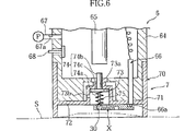
図6に示したように、装着体7は、上述したバイオセンサXおよび本体70を備えている。本体70は、円筒部71および底壁部72を有している。円筒部71は、装着部64の先端部を外套しうるように構成されている。底壁部72は、上方に向けて膨出した凸部73を有している。凸部73は、穿刺針74aを有する穿刺体74を保持するためのものであり、その開口部が底壁部72に貼着されたバイオセンサXによって覆われている。凸部73の上壁には穿刺体74の被押圧部74bを挿通するため貫通孔73aが設けられ、凸部73の周壁部には後述するポンプPの駆動時などにおける気体の移動を許容するための貫通孔73bが設けられている。凸部73内には、穿刺体74のフランジ部74cとバイオセンサXとの間に配置されたコイルバネ75が付勢状態で収容されている。このため、穿刺体74は、コイルバネ75によってフランジ部74cが凸部73の底壁に上方に向けて押し付けられた状態で保持されている。
【0051】
血糖値測定装置6はさらに、押圧ロッド65および一対のコネクタ66(図中には1つのコネクタのみ示している)を有している。押圧ロッド65は、押圧スイッチ63の操作によって先端方向に向けて駆動されるものである。押圧ロッド65は、たとえば公知のラッチ機構や電磁石を利用した機構により駆動される。各コネクタ66は、図外の電気回路に導通しており、上下方向に往復移動可能なコネクタピン66aを有している。各コネクタピン66aは、血糖値測定装置6に装着体7を装着したときに、バイオセンサXの端子部14b,15bに接触させるためのものである。
【0052】
装着部64には、その内部に連通する接続管67を介して、ポンプPが接続されている。接続管67には、装着部64の内部の圧力を検知するための圧力センサ67aが設けられている。ポンプPは、装着部64の内部の気体を外部に排出し、装着部64の内部を減圧するためのものである。ポンプPは、血糖値測定装置6の内部に収容されていてもよいし、血糖値測定装置6の外部に配置されていてもよい。ポンプPは、電動ポンプであっても、手動式のものであってもよい。ただし、本実施の形態においては、電動ポンプが採用されているものとする。
【0053】
装着部64には、開放弁68が設けられている。この開放弁68は、外部の空気を吸入し、装着部64の内部における圧力を大気圧に戻すためのものである。開放弁68は、たとえば電磁弁からなる。ただし、開放弁68は、手動により開放されるように構成されていてもよい。
【0054】
図7は、血糖値測定装置6の概略ブロック図である。血糖値測定装置6は、上述した表示部61、操作スイッチ62および圧力センサ67aの他に、制御部80、電流値測定部81、ポンプ駆動部82、開放弁駆動部83、および記憶部84を備えている。
【0055】
制御部80は、各部61,62,67a,81〜84の動作を制御するためのものであり、たとえばCPUによって構成されている。
【0056】
電流値測定部81は、バイオセンサXの作用極14および対極15に対して電圧を印加して、試薬部16に流れる電流を測定するためのものである。電流値測定部81は、装着部64に装着体7を装着した場合に、一対のコネクタ66を介してバイオセンサXの作用極14および対極15と導通するように構成されている。
【0057】
ポンプ駆動部82は制御部80の指示に基づいてポンプPを駆動するためのものであり、開放弁駆動部83は制御部80の指示に基づいて開放弁68を駆動するためのものである。
【0058】
記憶部84は、たとえばROMおよびRAMからなり、制御部80における制御に必要なプログラム、検量線データが記憶されている。記憶部84は、プログラムの実行時に必要な情報を一時的に記憶する役割も有している。検量線データは、たとえば測定された電流値が変換されて求められる電圧値とグルコース濃度との対応関係を示すものとして記憶されている。検量線データは、たとえば数式や対応テーブルとして記憶されている。
【0059】
次いで、血糖値測定装置6および装着体7を用いた血糖値測定動作を説明する。まず、図6R>6に示すように、血糖値測定装置6に対して装着体7を装着した上で、装着体7の先端を、使用者の皮膚Sの適当な部位、たとえば腕や指先に押し当てる。このとき、装着体7の先端開口が皮膚Sにより閉塞される。
【0060】
次に、血糖値測定装置6の操作スイッチ62を押下する。すると、制御部80は、ポンプ駆動部82に対して制御信号を送り、ポンプPを駆動させる。これにより、装着部64および装着体7の内部は、徐々に減圧状態となる。この間、制御部80は、圧力センサ67aからの出力値を常時監視している。皮膚Sは、減圧に伴って徐々に隆起し、図8に示すように、バイオセンサXと当接する。このとき、バイオセンサXの第1および第2貫通孔11,12は皮膚Sにより塞がれる。
【0061】
ポンプPの駆動は、圧力センサ67aが、バイオセンサXに密着するまで皮膚Sが隆起する圧力として予め設定された圧力を検知した時点で停止され、減圧過程は終了する。このとき、減圧過程が終了した情報は、たとえば表示部61において表示される。
【0062】
次に、使用者の操作によって血糖値測定装置6の押圧スイッチ63が押圧され、押圧ロッド65が瞬間的に移動させられる。使用者は、表示部61の表示にしたがって減圧終了を確認した後、押圧スイッチ63を押圧すればよい。これにより、押圧ロッド65が穿刺体74の被押圧部74bに当接し、穿刺体74を皮膚Sに向けて押し出す。このとき、穿刺体74の穿刺針74aは、バイオセンサXの貫通孔30から液溜部4に入り込んで第1貫通孔11から抜け出し、図9に示すように皮膚Sを穿刺する。ただし、本発明ではこのような構成に代えて、ポンプPによる減圧開始から数秒後、自動的に穿刺針74aが皮膚Sを穿刺するように構成してもよい。
【0063】
次に、図10に示すように、押圧ロッド65は、たとえば図示しないバネの付勢力によって元の位置まで復帰動する。また、穿刺針74aは、バネ75の付勢力によって、元の位置に復帰し、皮膚Sから穿刺針74aが抜き取られる。このとき、穿刺針74aにより適度に穿刺された皮膚Sからは、血液Bが出液する。図11に示したように、皮膚Sにおける穿刺箇所は、バイオセンサXの液溜部4に臨んでいるので、皮膚Sから出液した血液Bは、直ちに、液溜部4に導入され、液溜部4に保持される。このとき、第1貫通孔11が皮膚Sにより塞がれているので、液溜部4内に保持された血液は、外部に漏洩することが抑制されている。
【0064】
目的量の血液Bが液溜部4に蓄積されたとき、液溜部4に露出する一対の検知電極31,32の一端部31a,32aが液絡する。この液絡は、検知用電極31,32およびコネクタピン66aを介して制御部80(図7参照)により検出される。制御部80が検知用電極31,32の液絡を検知した場合には、制御部80からの命令に基づいて開放弁68が開放され、装着体7の内部が大気開放される(図7および図8参照)。これにより、図1212に示すように、装着部64(図6参照)の内部の負圧状態が解除されて皮膚Sの隆起がなくなり、バイオセンサXの第1および第2貫通孔11,12が開放される。負圧の解除は、使用者自身が装着体7から皮膚Sを離すことにより行ってもよい。
【0065】
第2貫通孔12が開放された場合には、液溜部4に保持していた血液Bは、毛細管現象により、キャピラリ5に対して勢いよく即座に導入される。このようにバイオセンサXでは、目的量の血液Bが液溜部4に確保されてから、この血液Bがキャピラリ5内部に対して勢いよく即座に導入されるため、血液Bの粘度などによって血糖値測定における血液導入時間が大きく左右されるのを適切に抑制することができる。
【0066】
キャピラリ5内へ導入された血液Bは、試薬部16を溶解させ、キャピラリ5内に液相反応系を構築する。このとき、血液Bに含まれるグルコースは、試薬部16に含まれていた酸化還元酵素の作用により酸化される。この反応によってグルコースから取り出される電子は、酵素を介して電子伝達物質に渡される。すなわち、酵素によって、電子伝達物質が還元される。この後、一対のコネクタ66を介して、作用極14および対極15に所定の電位を付与すると(図4参照)、液相反応系から酸化電流が取り出される。電流値測定部81は、この酸化電流を測定し、制御部80は、酸化電流、および記憶部84に格納されている検量線、演算用プログラムに基づいてグルコース濃度を演算する(図7参照)。
【0067】
制御部80で処理された演算結果は、表示部61にて表示され、使用者に知らされる(図5R>5および図7参照)。使用済みのバイオセンサXおよび穿刺体74は、使用者が血糖値測定装置6から装着体7を取り外すことにより、血糖値測定装置6から取り除かれる。
【0068】
次に、本発明の第2の実施の形態について、図13ないし図15を参照して説明する。これらの図においては、本発明の第1の実施に形態において説明した部材または要素と同様なものについては同一の符号を付してあり、それらについては、本実施の形態における重複説明は省略する。
【0069】
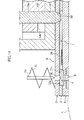
図13および図14に示すように、本実施の形態に係るバイオセンサX′では、キャピラリ5内の気体を排出するための空気抜き穴39′が基板1′ではなく、カバー3′に設けられている。空気抜き穴39′は、外部に向けて広がるようにテーパ状に開口しており、キャピラリ5に連通している。装着体7の底壁72′には、空気抜き穴39′に対応する部分に貫通孔79′が形成されている。血糖値測定装置6′の装着部64′には、空気抜き穴39′および貫通孔79′に繋がる貫通孔64a′が形成されている。貫通孔64a′はさらに、貫通孔64b′を介して装着部64′の内部と連通している。空気抜き穴39′、貫通孔64a′,79′には、開閉ピン69′が嵌め込まれている。開閉ピン69′は、制御部80(図7参照)からの命令に基づいて、図外の駆動機構によって往復移動可能なように構成されている。したがって、開閉ピン69′を往復駆動させることにより、バイオセンサX′の空気抜き穴39′を開閉することができる。
【0070】
次いで、血糖値測定装置6′および装着体7′を用いた血糖値測定動作について説明する。目的量の血液Bが液溜部4に蓄積され、それが制御部80(図7参照)において検知されるまでの動作は、本発明の第1の実施の形態と同様である。
【0071】
目的量の血液が液溜部4に蓄積されたことが検知された場合には、制御部80(図7参照)からの命令に基づいて、開閉ピン69′は図中の上方へと変位し、空気抜き穴39′が開放される。開閉ピン69′の先端が、貫通孔64b′を超えるまで変位すると、空気抜き穴39′が装着部64′の内部と連通する。これにより、液溜部4に滞留していた血液Bは、図15に示すように、毛細管現象により、キャピラリ5の内部へと勢いよく即座に導入される。これ以降の過程については、本発明の第1の実施の形態と同様である。
【0072】
血糖値測定装置6′および装着体7′を用いた血糖値測定においても、目的量の血液Bが液溜部4に確保されてから、この血液Bがキャピラリ5の内部に対して勢いよく即座に導入されるため、血液Bの粘度によって、血糖値測定における血液導入時間が大きく左右されるのを適切に抑制することができ、その結果、良好な測定を再現性よく行うことが可能となる。
【0073】
上述の説明においては、特定物質の濃度を測定する手段として、電極を用いて酸化電流を検出する方法を述べたが、本発明ではこれに限らず、比色により濃度を測定するように構成することもできる。具体的には、測定対象物質の酸化や還元に伴って還元や酸化される物質として、当該酸化還元反応において変色ないし吸収スペクトルの変化を伴う物質を使用することにより、比色測定による濃度測定を行うことができる。
【0074】
以上、血糖値測定に供されるバイオセンサ、装着体、および濃度測定装置を例にして、本発明を説明したが、本発明の範囲はこれに限定されるものではない。たとえば、グルコース濃度に代わり、コレステロールや乳酸値等の濃度を求める場合に上記実施形態の構成を用いてもよいし、また、試薬部に酵素などを含まない非バイオ的なセンサとして構成してもよい。
【図面の簡単な説明】
【図1】 図1は、本発明の第1の実施の形態に係るバイオセンサの一例を示す全体斜視図である。
【図2】 図2は、図1のII−II線に沿う断面図である。
【図3】 図3は、図1に示すバイオセンサの分解斜視図である。
【図4】 図4は、図1のIV−IV線に沿う断面図である。
【図5】 図5は、本発明の第1の実施の形態に係る濃度測定装置の全体斜視図である。
【図6】 図6は、図5のVI−VI線に沿う断面図である。
【図7】 図7は、図5に示す濃度測定装置のブロック図である。
【図8】 図8は、穿刺動作を説明するための図6に相当する断面図である。
【図9】 図9は、穿刺動作を説明するための図6に相当する断面図である。
【図10】 図10は、穿刺動作を説明するための図6に相当する断面図である。
【図11】 図11は、図10の要部拡大断面図である。
【図12】 図12は、バイオセンサへの血液導入動作を説明するための図11に相当する要部拡大断面図である。
【図13】 図13は、本発明の第2の実施の形態に係る濃度測定装置を説明するための図5のVI−VI線に沿う断面に相当する断面図である。
【図14】 図14は、図13の要部拡大断面図である。
【図15】 図15は、バイオセンサへの血液導入動作を説明するための図14に相当する要部拡大断面図である。
【図16】 図16は、従来のバイオセンサの分解斜視図である。
【図17】 図17は、組立てた状態における従来のバイオセンサの、図16のXVII−XVII線に沿う断面に相当する断面図である。【Technical field】
[0001]
The present invention relates to a measurement tool used when measuring the concentration of a specific component in a sample solution, a mounting body provided with the same, and a concentration measuring device used by mounting the mounting body.
[Background]
[0002]
In a blood glucose level measuring apparatus which is an example of a concentration measuring apparatus, a method of measuring the concentration of glucose contained in blood using an oxidation-reduction reaction using an oxidoreductase as a catalyst is widely adopted. When using the blood glucose level measuring device, a blood glucose level is measured by supplying blood to the measuring device after a measuring device for providing an enzyme reaction field is attached to the concentration measuring device. As a measurement tool used in a blood glucose level measuring apparatus, a capillary-type biosensor that utilizes a capillary phenomenon when blood is introduced into an enzyme reaction field is widely used.
[0003]
An example of a biosensor employing a capillary method is shown in FIGS. 16 is an exploded perspective view of the
[0004]
The
[0005]
In blood glucose level measurement using the
[0006]
As a method of collecting blood to be introduced into the
[0007]
On the other hand, in recent years, as disclosed in, for example, Japanese Patent Laid-Open No. 2000-231, puncture of the skin with a lancet (introduction of blood into the biosensor 90) and measurement of blood glucose level are performed in one apparatus A blood glucose level measuring apparatus having a puncture function capable of performing the above has also been proposed.
[0008]
However, in the
[0009]
On the other hand, in a blood glucose level measuring device having a puncture function, it is often difficult to visually confirm the blood bleeding position, and the following problems may occur. The first problem is that it is difficult to achieve high reproducibility for the blood supply to the
[0010]
If the blood introduction time varies greatly from blood to blood, the degree of progress of the enzyme reaction started when the
DISCLOSURE OF THE INVENTION
[0011]
The present invention makes it possible to appropriately introduce a necessary amount of sample liquid into the capillary without requiring strict visual confirmation when supplying the sample liquid to the measurement tool, and to perform good measurement with high reproducibility. The purpose is to be able to do it.
[0012]
A measurement tool provided by the first aspect of the present invention includes a capillary for moving a sample solution, a liquid reservoir communicating with the capillary and holding a sample solution to be introduced into the capillary, And a liquid introduction selection means for selecting whether or not to introduce the sample liquid held in the liquid reservoir into the capillary.
[0013]
The measurement tool of the present invention is configured, for example, as including a substrate and a cover that forms a capillary together with the substrate.
[0014]
For example, the liquid reservoir is configured to communicate with the capillary and to have an inlet for introducing the sample liquid. The liquid reservoir is preferably formed in a form in which the substrate and the cover are continuously penetrated in the thickness direction thereof. The internal volume of the liquid reservoir is preferably equal to or greater than the internal volume of the capillary.
[0015]
The introduction port is formed in, for example, a substrate or a cover. The introduction port is preferably formed so as to be wider than the entrance of the capillary. Then, the sample liquid can be introduced more easily than when the sample liquid is directly introduced into the capillary. In the vicinity of the introduction port, it is preferable to provide an adhesion layer having higher adhesion to the skin than the substrate or cover. The adhesive layer is constituted by, for example, a close contact member fitted in the introduction port. The contact member may be disposed so as to cover the peripheral edge or the peripheral part of the introduction port.
[0016]
The liquid introduction selection means is configured to have a discharge port for discharging the gas in the capillary, for example. In this case, both the inlet and the outlet are preferably formed on the substrate or the cover. Then, when blood as a sample solution is introduced, when the measurement tool is brought into close contact with the skin, both the inlet and the outlet can be simultaneously closed by the skin.
[0017]
It is preferable that the measurement tool of the present invention is formed to include a detection unit that is used to detect whether a target amount of the sample liquid is supplied to the liquid reservoir.
[0018]
The detection means is configured to have, for example, a first detection electrode and a second detection electrode. The first and second detection electrodes are preferably formed so that at least a part thereof is exposed inside the liquid reservoir. In this case, the detection means detects whether or not the sample liquid is in liquid junction between the first detection electrode and the second detection electrode, so that a target amount of the sample liquid is supplied to the liquid reservoir. It is comprised so that it can be detected.
[0019]
The measurement tool of the present invention is configured to include a first measurement electrode and a second measurement electrode so that the concentration of a specific component in a sample solution can be measured by, for example, an electrochemical technique. In this case, the capillary of A reagent part is formed inside. This reagent part is formed in a solid form that dissolves when a sample solution is supplied to the capillary. In this case, the first measurement electrode and the second measurement electrode are used to apply a voltage to the reaction system constructed by the reagent part and the sample solution when the reagent part is dissolved. In this configuration, it is preferable that the first detection electrode is conductively connected to the first measurement electrode and the second detection electrode is conductively connected to the second measurement electrode. Then, it becomes possible to detect whether or not the sample solution has been supplied using an electric circuit necessary for concentration measurement.
[0020]
According to a second aspect of the present invention, there is provided a mounting body used by being mounted on a concentration measuring device for measuring the concentration of a specific component in a sample liquid, wherein the measurement has a capillary for moving the sample liquid. In the mounting body provided with a tool, the measurement tool communicates with the capillary and holds a sample liquid to be introduced into the capillary, and a sample liquid held in the liquid reservoir. There is provided a mounting body comprising liquid introduction selection means for selecting whether or not to introduce into the capillary.
[0021]
The measurement tool is configured to include, for example, a substrate and a cover that forms a capillary together with the substrate.
[0022]
The wearing body according to the present invention is configured to further include a puncture body having a puncture needle. In this case, the liquid reservoir is preferably configured so that the substrate and the cover are continuously penetrated in the thickness direction so that the puncture needle can be inserted therethrough.
[0023]
The liquid introduction selection means is configured to have a discharge port for discharging the gas in the capillary, for example. In this case, liquid introduction Choice The means is configured to select whether or not the sample liquid is introduced into the capillary by selecting a state where the discharge port is opened and a state where the outlet is closed.
[0024]
For example, the discharge port may be configured to be opened and closed by skin or the like, or a mechanism for opening and closing the discharge port may be provided for the concentration measuring device, and the mechanism may be configured to be opened and closed by the mechanism.
[0025]
In a third aspect of the present invention, a concentration measuring apparatus for mounting and using a mounting body including a measuring tool and measuring the concentration of a specific component in a sample solution, the measuring tool being A capillary for moving the sample liquid, a liquid reservoir for communicating with the capillary and holding the sample liquid to be introduced into the capillary, and a sample liquid held in the liquid reservoir for the capillary And a liquid introduction selection means for selecting whether or not to introduce the liquid into the inside, and a selection means for selecting whether or not the sample liquid is introduced into the capillary. There is provided a concentration measuring device characterized by comprising:
[0026]
The liquid introduction selection means is configured to have a discharge port for discharging the gas in the capillary to the outside, for example. On the other hand, a selection means is comprised as what has an opening-and-closing member for opening and closing a discharge port, for example.
[0027]
Measuring device is taken from the skin sample When configured to supply liquid directly, the outlet is, for example, sample When collecting the liquid, it may be opened and closed by selecting whether or not to contact the skin. In this case, the concentration measuring device may be configured to select whether or not the skin is brought into contact with the discharge port by selecting the degree to which the skin is raised. The selection of the degree of raising the skin can be performed by selecting the degree of negative pressure acting on the skin, for example. In order to apply a negative pressure to the skin, a negative pressure generator may be provided in the concentration measuring device. In this case, the negative pressure generating unit constitutes a selection means for selecting the liquid introduction into the capillary. The negative pressure generator may be electric or manual.
[0028]
As the measuring tool, it is preferable to use a measuring tool provided with a detecting means used for detecting whether or not a target amount of the sample liquid is supplied to the liquid reservoir. In this case, the concentration measuring apparatus is configured to further include a determination unit for determining whether or not a target amount of the sample liquid is supplied to the liquid reservoir using the detection unit.
[0029]
According to a fourth aspect of the present invention, there is provided a concentration measuring device for mounting and using a mounting body equipped with a measuring tool, and for measuring the concentration of a specific component in a sample solution, the measuring tool being A capillary for moving the sample liquid, a liquid reservoir for communicating with the capillary and holding the sample liquid to be introduced into the capillary, and whether a target amount of the sample liquid has been supplied to the liquid reservoir. And a detecting means used for detecting whether or not a target amount of sample liquid is supplied to the liquid reservoir using the detecting means. There is provided a concentration measuring apparatus, further comprising a determination means for performing the above.
BEST MODE FOR CARRYING OUT THE INVENTION
[0030]
The best mode for carrying out the present invention will be described below with reference to the drawings. However, in the following, a biosensor, a wearing body, and a blood glucose level measuring device configured to measure a blood glucose level will be described.
[0031]
First, a first embodiment of the present invention will be described.
[0032]
As shown in FIGS. 1 and 2, the biosensor X is configured as a disposable type that is used by being attached to a blood glucose level measuring device. The biosensor X has a structure in which a
[0033]
As shown in FIGS. 2 and 3, the
[0034]
The first through-
[0035]
The
[0036]
The
[0037]
As clearly shown in FIG. 3, a working
[0038]
The
[0039]
The
[0040]
As shown in FIG. 3, the
[0041]
As shown in FIGS. 2 and 3, a pair of
[0042]
As shown in FIG. 4, the
[0043]
As shown in FIG. 2, the
[0044]
The first circular recess 11 a of the
[0045]
As described above, the
[0046]
It is preferable that the surface constituting the outer extension of the
[0047]
The biosensor X is configured such that the sample liquid supplied to the
[0048]
As shown in FIG. 5, the blood sugar
[0049]
The
[0050]
As shown in FIG. 6, the mounting
[0051]
The blood glucose
[0052]
A pump P is connected to the mounting
[0053]
An
[0054]
FIG. 7 is a schematic block diagram of the blood sugar
[0055]
The
[0056]
The current
[0057]
The
[0058]
The
[0059]
Next, a blood sugar level measuring operation using the blood sugar
[0060]
Next, the
[0061]
The driving of the pump P is stopped when the
[0062]
Next, the
[0063]
Next, as shown in FIG. Pressing The
[0064]
When the target amount of blood B is accumulated in the
[0065]
When the second through
[0066]
The blood B introduced into the
[0067]
The calculation result processed by the
[0068]
Next, a second embodiment of the present invention will be described with reference to FIGS. In these drawings, the same reference numerals are given to the same members or elements as those described in the first embodiment of the present invention. of The duplicate description in the form is omitted.
[0069]
As shown in FIGS. 13 and 14, in the biosensor X ′ according to the present embodiment, an
[0070]
Next, the blood sugar level measuring operation using the blood sugar level measuring device 6 'and the wearing body 7' will be described. The operation until the target amount of blood B is accumulated in the
[0071]
When it is detected that a target amount of blood has accumulated in the
[0072]
Also in blood glucose measurement using the blood
[0073]
In the above description, as a means for measuring the concentration of a specific substance, a method for detecting an oxidation current using an electrode has been described. You can also. Specifically, by using a substance that undergoes a color change or a change in absorption spectrum in the oxidation-reduction reaction as a substance that is reduced or oxidized along with oxidation or reduction of the measurement target substance, concentration measurement by colorimetry is performed. It can be carried out.
[0074]
As described above, the present invention has been described by taking the biosensor, the mounted body, and the concentration measuring device used for blood glucose level measurement as examples, but the scope of the present invention is not limited to this. For example, the configuration of the above embodiment may be used when determining a concentration such as cholesterol or lactic acid value instead of the glucose concentration, or may be configured as a non-biological sensor that does not include an enzyme or the like in the reagent part. Good.
[Brief description of the drawings]
FIG. 1 is an overall perspective view showing an example of a biosensor according to a first embodiment of the present invention.
FIG. 2 is a sectional view taken along line II-II in FIG.
FIG. 3 is an exploded perspective view of the biosensor shown in FIG.
4 is a cross-sectional view taken along line IV-IV in FIG. 1. FIG.
FIG. 5 is an overall perspective view of the concentration measuring apparatus according to the first embodiment of the present invention.
6 is a cross-sectional view taken along the line VI-VI in FIG. 5;
FIG. 7 is a block diagram of the concentration measuring apparatus shown in FIG.
FIG. 8 is a cross-sectional view corresponding to FIG. 6 for explaining the puncturing operation.
FIG. 9 is a cross-sectional view corresponding to FIG. 6 for explaining the puncturing operation.
FIG. 10 is a cross-sectional view corresponding to FIG. 6 for explaining the puncturing operation.
FIG. 11 is an enlarged cross-sectional view of a main part of FIG.
FIG. 12 is an enlarged cross-sectional view of the main part corresponding to FIG. 11 for explaining the blood introduction operation to the biosensor.
FIG. 13 is a diagram of FIG. 5 for explaining a concentration measuring apparatus according to a second embodiment of the present invention. VI-VI It is sectional drawing equivalent to the cross section along a line.
FIG. 14 is an enlarged cross-sectional view of a main part of FIG.
FIG. 15 is an enlarged cross-sectional view corresponding to FIG. 14 for explaining the blood introduction operation to the biosensor.
FIG. 16 is an exploded perspective view of a conventional biosensor.
FIG. 17 is a cross-sectional view of a conventional biosensor in an assembled state, corresponding to a cross section taken along line XVII-XVII in FIG.
Claims (9)
前記キャピラリに連通し、かつ前記キャピラリに導入すべき試料液を保持するための液溜部と、
前記液溜部に保持させた試料液を、前記キャピラリ内に導入するか否かを選択するための液導入選択手段と、を備え、
基板と、この基板とともに前記キャピラリを構成するカバーと、を備えており、
前記液溜部は、前記キャピラリに連通し、かつ試料液を導入するための導入口を有しており、
前記導入口は、前記基板または前記カバーに形成されている、測定用具。A capillary for moving the sample solution;
A liquid reservoir for communicating with the capillary and holding a sample liquid to be introduced into the capillary;
A liquid introduction selection means for selecting whether or not to introduce the sample liquid held in the liquid reservoir into the capillary ,
A substrate, and a cover that constitutes the capillary together with the substrate,
The liquid reservoir is communicated with the capillary and has an inlet for introducing a sample liquid,
The introduction port is a measurement tool formed in the substrate or the cover .
前記導入口および前記排出口の双方は、前記基板または前記カバーに形成されている、請求項1に記載の測定用具。The liquid introduction selection means has a discharge port for discharging the gas in the capillary,
Wherein both the inlet and the outlet is formed on the substrate or the cover, the measurement device of claim 1.
前記第1検知用電極は前記第1測定用電極に導通接続され、前記第2検知用電極は前記第2測定用電極に導通接続されている、請求項8に記載の測定用具。A reagent part that is provided in the capillary and dissolves when a sample liquid is supplied to the capillary, and a voltage is applied to the reaction system constructed by the reagent part and the sample liquid when the reagent part is dissolved. A first measurement electrode and a second measurement electrode for applying,
The measurement tool according to claim 8 , wherein the first detection electrode is conductively connected to the first measurement electrode, and the second detection electrode is conductively connected to the second measurement electrode.
Applications Claiming Priority (3)
| Application Number | Priority Date | Filing Date | Title |
|---|---|---|---|
| JP2001275532 | 2001-09-11 | ||
| JP2001275532 | 2001-09-11 | ||
| PCT/JP2002/009132 WO2003025559A1 (en) | 2001-09-11 | 2002-09-06 | Measuring instrument, installation body, and density measurer |
Related Child Applications (1)
| Application Number | Title | Priority Date | Filing Date |
|---|---|---|---|
| JP2008291658A Division JP4621843B2 (en) | 2001-09-11 | 2008-11-14 | Wearing body and concentration measuring device |
Publications (2)
| Publication Number | Publication Date |
|---|---|
| JPWO2003025559A1 JPWO2003025559A1 (en) | 2004-12-24 |
| JP4246629B2 true JP4246629B2 (en) | 2009-04-02 |
Family
ID=19100382
Family Applications (2)
| Application Number | Title | Priority Date | Filing Date |
|---|---|---|---|
| JP2003529138A Expired - Fee Related JP4246629B2 (en) | 2001-09-11 | 2002-09-06 | Measuring tool |
| JP2008291658A Expired - Fee Related JP4621843B2 (en) | 2001-09-11 | 2008-11-14 | Wearing body and concentration measuring device |
Family Applications After (1)
| Application Number | Title | Priority Date | Filing Date |
|---|---|---|---|
| JP2008291658A Expired - Fee Related JP4621843B2 (en) | 2001-09-11 | 2008-11-14 | Wearing body and concentration measuring device |
Country Status (6)
| Country | Link |
|---|---|
| US (1) | US7640047B2 (en) |
| EP (1) | EP1426758B1 (en) |
| JP (2) | JP4246629B2 (en) |
| CN (1) | CN1282870C (en) |
| AT (1) | ATE519420T1 (en) |
| WO (1) | WO2003025559A1 (en) |
Families Citing this family (70)
| Publication number | Priority date | Publication date | Assignee | Title |
|---|---|---|---|---|
| US9155496B2 (en) | 1997-03-04 | 2015-10-13 | Dexcom, Inc. | Low oxygen in vivo analyte sensor |
| US7899511B2 (en) | 2004-07-13 | 2011-03-01 | Dexcom, Inc. | Low oxygen in vivo analyte sensor |
| US20030032874A1 (en) | 2001-07-27 | 2003-02-13 | Dexcom, Inc. | Sensor head for use with implantable devices |
| US7004928B2 (en) | 2002-02-08 | 2006-02-28 | Rosedale Medical, Inc. | Autonomous, ambulatory analyte monitor or drug delivery device |
| US9247901B2 (en) | 2003-08-22 | 2016-02-02 | Dexcom, Inc. | Systems and methods for replacing signal artifacts in a glucose sensor data stream |
| US8010174B2 (en) | 2003-08-22 | 2011-08-30 | Dexcom, Inc. | Systems and methods for replacing signal artifacts in a glucose sensor data stream |
| US8260393B2 (en) | 2003-07-25 | 2012-09-04 | Dexcom, Inc. | Systems and methods for replacing signal data artifacts in a glucose sensor data stream |
| US7052652B2 (en) * | 2003-03-24 | 2006-05-30 | Rosedale Medical, Inc. | Analyte concentration detection devices and methods |
| US7074307B2 (en) | 2003-07-25 | 2006-07-11 | Dexcom, Inc. | Electrode systems for electrochemical sensors |
| US7761130B2 (en) | 2003-07-25 | 2010-07-20 | Dexcom, Inc. | Dual electrode system for a continuous analyte sensor |
| US8622905B2 (en) | 2003-08-01 | 2014-01-07 | Dexcom, Inc. | System and methods for processing analyte sensor data |
| US20190357827A1 (en) | 2003-08-01 | 2019-11-28 | Dexcom, Inc. | Analyte sensor |
| US8275437B2 (en) | 2003-08-01 | 2012-09-25 | Dexcom, Inc. | Transcutaneous analyte sensor |
| US6931327B2 (en) | 2003-08-01 | 2005-08-16 | Dexcom, Inc. | System and methods for processing analyte sensor data |
| US20080119703A1 (en) | 2006-10-04 | 2008-05-22 | Mark Brister | Analyte sensor |
| US9135402B2 (en) | 2007-12-17 | 2015-09-15 | Dexcom, Inc. | Systems and methods for processing sensor data |
| US20140121989A1 (en) | 2003-08-22 | 2014-05-01 | Dexcom, Inc. | Systems and methods for processing analyte sensor data |
| US7920906B2 (en) | 2005-03-10 | 2011-04-05 | Dexcom, Inc. | System and methods for processing analyte sensor data for sensor calibration |
| US9247900B2 (en) | 2004-07-13 | 2016-02-02 | Dexcom, Inc. | Analyte sensor |
| DE602004029092D1 (en) | 2003-12-05 | 2010-10-21 | Dexcom Inc | CALIBRATION METHODS FOR A CONTINUOUSLY WORKING ANALYTIC SENSOR |
| US11633133B2 (en) | 2003-12-05 | 2023-04-25 | Dexcom, Inc. | Dual electrode system for a continuous analyte sensor |
| US8287453B2 (en) | 2003-12-05 | 2012-10-16 | Dexcom, Inc. | Analyte sensor |
| US8423114B2 (en) | 2006-10-04 | 2013-04-16 | Dexcom, Inc. | Dual electrode system for a continuous analyte sensor |
| US8364231B2 (en) | 2006-10-04 | 2013-01-29 | Dexcom, Inc. | Analyte sensor |
| WO2005104949A1 (en) | 2004-04-15 | 2005-11-10 | Roche Diagnostics Gmbh | Integrated spot monitoring device with fluid sensor |
| US9101302B2 (en) | 2004-05-03 | 2015-08-11 | Abbott Diabetes Care Inc. | Analyte test device |
| US8792955B2 (en) | 2004-05-03 | 2014-07-29 | Dexcom, Inc. | Transcutaneous analyte sensor |
| US20050277849A1 (en) * | 2004-06-10 | 2005-12-15 | Daniel Wong | Vacuum sample expression device |
| US20060016700A1 (en) | 2004-07-13 | 2006-01-26 | Dexcom, Inc. | Transcutaneous analyte sensor |
| US7857760B2 (en) | 2004-07-13 | 2010-12-28 | Dexcom, Inc. | Analyte sensor |
| US20060270922A1 (en) | 2004-07-13 | 2006-11-30 | Brauker James H | Analyte sensor |
| US8565848B2 (en) | 2004-07-13 | 2013-10-22 | Dexcom, Inc. | Transcutaneous analyte sensor |
| US8452368B2 (en) | 2004-07-13 | 2013-05-28 | Dexcom, Inc. | Transcutaneous analyte sensor |
| US7783333B2 (en) | 2004-07-13 | 2010-08-24 | Dexcom, Inc. | Transcutaneous medical device with variable stiffness |
| US20060020192A1 (en) | 2004-07-13 | 2006-01-26 | Dexcom, Inc. | Transcutaneous analyte sensor |
| US20090076360A1 (en) | 2007-09-13 | 2009-03-19 | Dexcom, Inc. | Transcutaneous analyte sensor |
| US8133178B2 (en) | 2006-02-22 | 2012-03-13 | Dexcom, Inc. | Analyte sensor |
| JP2007050100A (en) * | 2005-08-18 | 2007-03-01 | Rohm Co Ltd | Chip for sampling specimen |
| US8801631B2 (en) | 2005-09-30 | 2014-08-12 | Intuity Medical, Inc. | Devices and methods for facilitating fluid transport |
| US8382681B2 (en) | 2005-09-30 | 2013-02-26 | Intuity Medical, Inc. | Fully integrated wearable or handheld monitor |
| US9757061B2 (en) | 2006-01-17 | 2017-09-12 | Dexcom, Inc. | Low oxygen in vivo analyte sensor |
| CN101511270B (en) * | 2006-09-19 | 2011-03-30 | 松下电器产业株式会社 | Blood sensor and blood examining instrument including same |
| US7831287B2 (en) | 2006-10-04 | 2010-11-09 | Dexcom, Inc. | Dual electrode system for a continuous analyte sensor |
| ITMI20070110A1 (en) * | 2007-01-25 | 2008-07-26 | Elio Scarano | SENSOR AND APPLIANCE FOR THE ANALYSIS OF GAS PRESENT IN THE BLOOD |
| JP5040409B2 (en) * | 2007-04-12 | 2012-10-03 | 富士ゼロックス株式会社 | Sensor chip and inspection device |
| WO2008136473A1 (en) * | 2007-04-29 | 2008-11-13 | Arkray, Inc. | Analysis instrument |
| US8417312B2 (en) | 2007-10-25 | 2013-04-09 | Dexcom, Inc. | Systems and methods for processing sensor data |
| US9839395B2 (en) | 2007-12-17 | 2017-12-12 | Dexcom, Inc. | Systems and methods for processing sensor data |
| US8396528B2 (en) | 2008-03-25 | 2013-03-12 | Dexcom, Inc. | Analyte sensor |
| EP2293719B1 (en) | 2008-05-30 | 2015-09-09 | Intuity Medical, Inc. | Body fluid sampling device -- sampling site interface |
| DK3639744T3 (en) | 2008-06-06 | 2022-02-21 | Intuity Medical Inc | BLOOD GLUCOSE METER AND METHOD OF USE |
| EP2299903B1 (en) | 2008-06-06 | 2021-01-27 | Intuity Medical, Inc. | Detection meter and mode of operation |
| US9357951B2 (en) | 2009-09-30 | 2016-06-07 | Dexcom, Inc. | Transcutaneous analyte sensor |
| EP3106871B1 (en) | 2009-11-30 | 2021-10-27 | Intuity Medical, Inc. | A method of verifying the accuracy of the operation of an analyte monitoring device |
| US20120238841A1 (en) * | 2010-04-15 | 2012-09-20 | Mark Castle | Sample capture in one step for test strips |
| US10330667B2 (en) | 2010-06-25 | 2019-06-25 | Intuity Medical, Inc. | Analyte monitoring methods and systems |
| JP5661424B2 (en) * | 2010-10-29 | 2015-01-28 | アークレイ株式会社 | Electrochemical sensor |
| CN102613978B (en) * | 2011-01-31 | 2014-12-03 | 厚美德生物科技股份有限公司 | Detection test piece |
| TW201231964A (en) | 2011-01-31 | 2012-08-01 | Hmd Biomedical Inc | Test strip |
| ES2964546T3 (en) | 2011-04-15 | 2024-04-08 | Dexcom Inc | Advanced analyte sensor calibration and error detection |
| CA2843945C (en) | 2011-08-03 | 2022-06-21 | Intuity Medical, Inc. | Devices and methods for body fluid sampling and analysis |
| JP6420309B2 (en) | 2013-03-11 | 2018-11-07 | キュー ヘルス インコーポレイテッド | System and method for analyte detection and quantification |
| CA2912283A1 (en) | 2013-06-21 | 2014-12-21 | Intuity Medical, Inc. | Analyte monitoring system with audible feedback |
| USD745423S1 (en) | 2014-05-12 | 2015-12-15 | Cue Inc. | Automated analyzer test cartridge and sample collection device for analyte detection |
| CN108136391B (en) | 2015-07-17 | 2021-01-26 | 克忧健康公司 | Systems and methods for enhanced detection and analyte quantitation |
| US10369567B2 (en) * | 2015-11-04 | 2019-08-06 | International Business Machines Corporation | Continuous, capacitance-based monitoring of liquid flows in a microfluidic device |
| BR112018072459A2 (en) | 2016-06-17 | 2019-03-12 | Hoffmann La Roche | test system for body fluid sample analysis, control method of transporting body fluid samples on test strips and body fluid sample analysis method |
| US20180049684A1 (en) * | 2016-08-19 | 2018-02-22 | Pavol Ovcik Berresford | Enhanced Lancing Device with Suction |
| US11237161B2 (en) | 2017-01-25 | 2022-02-01 | Cue Health Inc. | Systems and methods for enhanced detection and quantification of analytes |
| US11379578B1 (en) | 2020-10-16 | 2022-07-05 | Trend Micro Incorporated | Detecting malware by pooled analysis of sample files in a sandbox |
Family Cites Families (29)
| Publication number | Priority date | Publication date | Assignee | Title |
|---|---|---|---|---|
| JPS63180837A (en) * | 1987-01-21 | 1988-07-25 | Kimoto Denshi Kogyo Kk | Measuring apparatus of rain water component |
| US5065768A (en) * | 1988-09-13 | 1991-11-19 | Safe-Tec Clinical Products, Inc. | Self-sealing fluid conduit and collection device |
| US5147606A (en) * | 1990-08-06 | 1992-09-15 | Miles Inc. | Self-metering fluid analysis device |
| US5843691A (en) * | 1993-05-15 | 1998-12-01 | Lifescan, Inc. | Visually-readable reagent test strip |
| US5437999A (en) * | 1994-02-22 | 1995-08-01 | Boehringer Mannheim Corporation | Electrochemical sensor |
| IE72524B1 (en) * | 1994-11-04 | 1997-04-23 | Elan Med Tech | Analyte-controlled liquid delivery device and analyte monitor |
| JPH08304336A (en) * | 1995-05-10 | 1996-11-22 | Toto Ltd | Polarographic urine analyzing method and device therefor |
| JP3424399B2 (en) * | 1995-07-10 | 2003-07-07 | 東陶機器株式会社 | Urine component concentration measurement device |
| JP3621502B2 (en) | 1996-04-02 | 2005-02-16 | アプルス株式会社 | Lancet assembly |
| US6001307A (en) * | 1996-04-26 | 1999-12-14 | Kyoto Daiichi Kagaku Co., Ltd. | Device for analyzing a sample |
| ES2121565B1 (en) * | 1996-05-17 | 2000-12-16 | Mercury Diagnostics Inc | DISPOSABLE ITEM FOR USE IN A BODY FLUID SAMPLING DEVICE. |
| JP3604819B2 (en) * | 1996-07-11 | 2004-12-22 | 大日本印刷株式会社 | Body fluid analyzer |
| DE19753850A1 (en) * | 1997-12-04 | 1999-06-10 | Roche Diagnostics Gmbh | Sampling device |
| JP3382853B2 (en) | 1998-04-09 | 2003-03-04 | 松下電器産業株式会社 | Body fluid testing device |
| JP3873093B2 (en) | 1998-06-15 | 2007-01-24 | アークレイ株式会社 | Lancet-integrated body fluid measuring device and attached body to be used by attaching to this body fluid measuring device |
| WO2000040150A1 (en) * | 1999-01-04 | 2000-07-13 | Terumo Kabushiki Kaisha | Assembly having lancet and means for collecting and detecting body fluid |
| JP2000258382A (en) | 1999-03-05 | 2000-09-22 | Arkray Inc | Specimen small-quantity-type bio sensor |
| US6368563B1 (en) | 1999-03-12 | 2002-04-09 | Integ, Inc. | Collection well for body fluid tester |
| JP3499767B2 (en) * | 1999-03-19 | 2004-02-23 | 日本電信電話株式会社 | Microelectrode for histamine measurement and sensor for histamine measurement |
| CN1217623C (en) * | 1999-12-13 | 2005-09-07 | 爱科来株式会社 | Body fluid measuring apparatus with lancet and lancet holder used for the measuring apparatus |
| US6406919B1 (en) | 1999-12-16 | 2002-06-18 | Biosafe Laboratories, Inc. | Whole blood collection device and method |
| DE60135692D1 (en) * | 2000-07-26 | 2008-10-16 | Terumo Corp | Combination of a device and a chip for measuring bodily fluid components |
| CN1209621C (en) * | 2000-12-13 | 2005-07-06 | 松下电器产业株式会社 | Analytical element, and measuring instrument and substrate determining method using the same |
| GB0030929D0 (en) * | 2000-12-19 | 2001-01-31 | Inverness Medical Ltd | Analyte measurement |
| US6575188B2 (en) * | 2001-07-26 | 2003-06-10 | Handylab, Inc. | Methods and systems for fluid control in microfluidic devices |
| US7041068B2 (en) * | 2001-06-12 | 2006-05-09 | Pelikan Technologies, Inc. | Sampling module device and method |
| JP3610349B2 (en) * | 2002-08-06 | 2005-01-12 | キヤノン株式会社 | Liquid transfer device |
| EP1635170B1 (en) * | 2003-06-19 | 2012-09-26 | ARKRAY, Inc. | Analysis implement with opening in insulation film |
| JP4586130B2 (en) * | 2005-02-22 | 2010-11-24 | 丸石化成株式会社 | Sample liquid collection device |
-
2002
- 2002-09-06 AT AT02772840T patent/ATE519420T1/en not_active IP Right Cessation
- 2002-09-06 EP EP02772840A patent/EP1426758B1/en not_active Expired - Lifetime
- 2002-09-06 CN CNB028177657A patent/CN1282870C/en not_active Expired - Fee Related
- 2002-09-06 US US10/489,397 patent/US7640047B2/en not_active Expired - Fee Related
- 2002-09-06 WO PCT/JP2002/009132 patent/WO2003025559A1/en active Application Filing
- 2002-09-06 JP JP2003529138A patent/JP4246629B2/en not_active Expired - Fee Related
-
2008
- 2008-11-14 JP JP2008291658A patent/JP4621843B2/en not_active Expired - Fee Related
Also Published As
| Publication number | Publication date |
|---|---|
| EP1426758A4 (en) | 2007-11-28 |
| US20040242982A1 (en) | 2004-12-02 |
| ATE519420T1 (en) | 2011-08-15 |
| JPWO2003025559A1 (en) | 2004-12-24 |
| JP4621843B2 (en) | 2011-01-26 |
| CN1554019A (en) | 2004-12-08 |
| WO2003025559A1 (en) | 2003-03-27 |
| US7640047B2 (en) | 2009-12-29 |
| CN1282870C (en) | 2006-11-01 |
| JP2009066425A (en) | 2009-04-02 |
| EP1426758A1 (en) | 2004-06-09 |
| EP1426758B1 (en) | 2011-08-10 |
Similar Documents
| Publication | Publication Date | Title |
|---|---|---|
| JP4246629B2 (en) | Measuring tool | |
| JP4282477B2 (en) | Analysis tool | |
| JP5232664B2 (en) | Blood sampling device | |
| EP1776924B1 (en) | Combination of a body fluid component measuring apparatus and a chip | |
| JP4602398B2 (en) | Body fluid sampling device | |
| JP3985022B2 (en) | Body fluid measuring device and insertion body used by being inserted into the body fluid measuring device | |
| EP1369083A1 (en) | Test strip container system | |
| JP2000000231A (en) | Lancet integrated type body fluid measuring instrument and attachment used by being attached to the body fluid measuring instrument | |
| EP1541087B1 (en) | Body fluid sampling device | |
| JP2004000600A (en) | Physiological sampling apparatus and method for using the sample | |
| WO2003006980A1 (en) | Analyzing apparatus, piercing element integrally installed body for temperature measuring device with analyzing apparatus, and body fluid sampling apparatus | |
| JP2000116629A (en) | Mounting body | |
| JPH11347018A (en) | Humor examination device | |
| JP2002034956A (en) | Component measuring device | |
| JP2000116626A (en) | Humor measuring apparatus and mounting body | |
| JP4280033B2 (en) | Body fluid collection tool | |
| JP4894038B2 (en) | Biosensor cartridge | |
| JP2002058661A (en) | Component measuring apparatus |
Legal Events
| Date | Code | Title | Description |
|---|---|---|---|
| A521 | Request for written amendment filed |
Free format text: JAPANESE INTERMEDIATE CODE: A523 Effective date: 20050831 |
|
| A621 | Written request for application examination |
Free format text: JAPANESE INTERMEDIATE CODE: A621 Effective date: 20050831 |
|
| A131 | Notification of reasons for refusal |
Free format text: JAPANESE INTERMEDIATE CODE: A131 Effective date: 20080916 |
|
| A521 | Request for written amendment filed |
Free format text: JAPANESE INTERMEDIATE CODE: A523 Effective date: 20081114 |
|
| TRDD | Decision of grant or rejection written | ||
| A01 | Written decision to grant a patent or to grant a registration (utility model) |
Free format text: JAPANESE INTERMEDIATE CODE: A01 Effective date: 20081216 |
|
| A01 | Written decision to grant a patent or to grant a registration (utility model) |
Free format text: JAPANESE INTERMEDIATE CODE: A01 |
|
| A61 | First payment of annual fees (during grant procedure) |
Free format text: JAPANESE INTERMEDIATE CODE: A61 Effective date: 20090108 |
|
| R150 | Certificate of patent or registration of utility model |
Free format text: JAPANESE INTERMEDIATE CODE: R150 |
|
| FPAY | Renewal fee payment (event date is renewal date of database) |
Free format text: PAYMENT UNTIL: 20120116 Year of fee payment: 3 |
|
| FPAY | Renewal fee payment (event date is renewal date of database) |
Free format text: PAYMENT UNTIL: 20120116 Year of fee payment: 3 |
|
| FPAY | Renewal fee payment (event date is renewal date of database) |
Free format text: PAYMENT UNTIL: 20120116 Year of fee payment: 3 |
|
| FPAY | Renewal fee payment (event date is renewal date of database) |
Free format text: PAYMENT UNTIL: 20130116 Year of fee payment: 4 |
|
| R250 | Receipt of annual fees |
Free format text: JAPANESE INTERMEDIATE CODE: R250 |
|
| R250 | Receipt of annual fees |
Free format text: JAPANESE INTERMEDIATE CODE: R250 |
|
| R250 | Receipt of annual fees |
Free format text: JAPANESE INTERMEDIATE CODE: R250 |
|
| LAPS | Cancellation because of no payment of annual fees |