JP4243197B2 - Intervertebral prosthesis - Google Patents
Intervertebral prosthesis Download PDFInfo
- Publication number
- JP4243197B2 JP4243197B2 JP2003574081A JP2003574081A JP4243197B2 JP 4243197 B2 JP4243197 B2 JP 4243197B2 JP 2003574081 A JP2003574081 A JP 2003574081A JP 2003574081 A JP2003574081 A JP 2003574081A JP 4243197 B2 JP4243197 B2 JP 4243197B2
- Authority
- JP
- Japan
- Prior art keywords
- cover plate
- prosthesis
- core
- plate
- guide
- Prior art date
- Legal status (The legal status is an assumption and is not a legal conclusion. Google has not performed a legal analysis and makes no representation as to the accuracy of the status listed.)
- Expired - Fee Related
Links
Images


Classifications
-
- A—HUMAN NECESSITIES
- A61—MEDICAL OR VETERINARY SCIENCE; HYGIENE
- A61F—FILTERS IMPLANTABLE INTO BLOOD VESSELS; PROSTHESES; DEVICES PROVIDING PATENCY TO, OR PREVENTING COLLAPSING OF, TUBULAR STRUCTURES OF THE BODY, e.g. STENTS; ORTHOPAEDIC, NURSING OR CONTRACEPTIVE DEVICES; FOMENTATION; TREATMENT OR PROTECTION OF EYES OR EARS; BANDAGES, DRESSINGS OR ABSORBENT PADS; FIRST-AID KITS
- A61F2/00—Filters implantable into blood vessels; Prostheses, i.e. artificial substitutes or replacements for parts of the body; Appliances for connecting them with the body; Devices providing patency to, or preventing collapsing of, tubular structures of the body, e.g. stents
- A61F2/02—Prostheses implantable into the body
- A61F2/30—Joints
- A61F2/44—Joints for the spine, e.g. vertebrae, spinal discs
- A61F2/442—Intervertebral or spinal discs, e.g. resilient
- A61F2/4425—Intervertebral or spinal discs, e.g. resilient made of articulated components
-
- A—HUMAN NECESSITIES
- A61—MEDICAL OR VETERINARY SCIENCE; HYGIENE
- A61F—FILTERS IMPLANTABLE INTO BLOOD VESSELS; PROSTHESES; DEVICES PROVIDING PATENCY TO, OR PREVENTING COLLAPSING OF, TUBULAR STRUCTURES OF THE BODY, e.g. STENTS; ORTHOPAEDIC, NURSING OR CONTRACEPTIVE DEVICES; FOMENTATION; TREATMENT OR PROTECTION OF EYES OR EARS; BANDAGES, DRESSINGS OR ABSORBENT PADS; FIRST-AID KITS
- A61F2/00—Filters implantable into blood vessels; Prostheses, i.e. artificial substitutes or replacements for parts of the body; Appliances for connecting them with the body; Devices providing patency to, or preventing collapsing of, tubular structures of the body, e.g. stents
- A61F2/02—Prostheses implantable into the body
- A61F2/30—Joints
- A61F2002/30001—Additional features of subject-matter classified in A61F2/28, A61F2/30 and subgroups thereof
- A61F2002/30316—The prosthesis having different structural features at different locations within the same prosthesis; Connections between prosthetic parts; Special structural features of bone or joint prostheses not otherwise provided for
- A61F2002/30329—Connections or couplings between prosthetic parts, e.g. between modular parts; Connecting elements
- A61F2002/30383—Connections or couplings between prosthetic parts, e.g. between modular parts; Connecting elements made by laterally inserting a protrusion, e.g. a rib into a complementarily-shaped groove
- A61F2002/30387—Dovetail connection
-
- A—HUMAN NECESSITIES
- A61—MEDICAL OR VETERINARY SCIENCE; HYGIENE
- A61F—FILTERS IMPLANTABLE INTO BLOOD VESSELS; PROSTHESES; DEVICES PROVIDING PATENCY TO, OR PREVENTING COLLAPSING OF, TUBULAR STRUCTURES OF THE BODY, e.g. STENTS; ORTHOPAEDIC, NURSING OR CONTRACEPTIVE DEVICES; FOMENTATION; TREATMENT OR PROTECTION OF EYES OR EARS; BANDAGES, DRESSINGS OR ABSORBENT PADS; FIRST-AID KITS
- A61F2/00—Filters implantable into blood vessels; Prostheses, i.e. artificial substitutes or replacements for parts of the body; Appliances for connecting them with the body; Devices providing patency to, or preventing collapsing of, tubular structures of the body, e.g. stents
- A61F2/02—Prostheses implantable into the body
- A61F2/30—Joints
- A61F2002/30001—Additional features of subject-matter classified in A61F2/28, A61F2/30 and subgroups thereof
- A61F2002/30316—The prosthesis having different structural features at different locations within the same prosthesis; Connections between prosthetic parts; Special structural features of bone or joint prostheses not otherwise provided for
- A61F2002/30329—Connections or couplings between prosthetic parts, e.g. between modular parts; Connecting elements
- A61F2002/30383—Connections or couplings between prosthetic parts, e.g. between modular parts; Connecting elements made by laterally inserting a protrusion, e.g. a rib into a complementarily-shaped groove
- A61F2002/3039—Connections or couplings between prosthetic parts, e.g. between modular parts; Connecting elements made by laterally inserting a protrusion, e.g. a rib into a complementarily-shaped groove with possibility of relative movement of the rib within the groove
- A61F2002/30392—Rotation
-
- A—HUMAN NECESSITIES
- A61—MEDICAL OR VETERINARY SCIENCE; HYGIENE
- A61F—FILTERS IMPLANTABLE INTO BLOOD VESSELS; PROSTHESES; DEVICES PROVIDING PATENCY TO, OR PREVENTING COLLAPSING OF, TUBULAR STRUCTURES OF THE BODY, e.g. STENTS; ORTHOPAEDIC, NURSING OR CONTRACEPTIVE DEVICES; FOMENTATION; TREATMENT OR PROTECTION OF EYES OR EARS; BANDAGES, DRESSINGS OR ABSORBENT PADS; FIRST-AID KITS
- A61F2/00—Filters implantable into blood vessels; Prostheses, i.e. artificial substitutes or replacements for parts of the body; Appliances for connecting them with the body; Devices providing patency to, or preventing collapsing of, tubular structures of the body, e.g. stents
- A61F2/02—Prostheses implantable into the body
- A61F2/30—Joints
- A61F2002/30001—Additional features of subject-matter classified in A61F2/28, A61F2/30 and subgroups thereof
- A61F2002/30316—The prosthesis having different structural features at different locations within the same prosthesis; Connections between prosthetic parts; Special structural features of bone or joint prostheses not otherwise provided for
- A61F2002/30329—Connections or couplings between prosthetic parts, e.g. between modular parts; Connecting elements
- A61F2002/30383—Connections or couplings between prosthetic parts, e.g. between modular parts; Connecting elements made by laterally inserting a protrusion, e.g. a rib into a complementarily-shaped groove
- A61F2002/3039—Connections or couplings between prosthetic parts, e.g. between modular parts; Connecting elements made by laterally inserting a protrusion, e.g. a rib into a complementarily-shaped groove with possibility of relative movement of the rib within the groove
- A61F2002/30397—Limited lateral translation of the rib within a larger groove
-
- A—HUMAN NECESSITIES
- A61—MEDICAL OR VETERINARY SCIENCE; HYGIENE
- A61F—FILTERS IMPLANTABLE INTO BLOOD VESSELS; PROSTHESES; DEVICES PROVIDING PATENCY TO, OR PREVENTING COLLAPSING OF, TUBULAR STRUCTURES OF THE BODY, e.g. STENTS; ORTHOPAEDIC, NURSING OR CONTRACEPTIVE DEVICES; FOMENTATION; TREATMENT OR PROTECTION OF EYES OR EARS; BANDAGES, DRESSINGS OR ABSORBENT PADS; FIRST-AID KITS
- A61F2/00—Filters implantable into blood vessels; Prostheses, i.e. artificial substitutes or replacements for parts of the body; Appliances for connecting them with the body; Devices providing patency to, or preventing collapsing of, tubular structures of the body, e.g. stents
- A61F2/02—Prostheses implantable into the body
- A61F2/30—Joints
- A61F2002/30001—Additional features of subject-matter classified in A61F2/28, A61F2/30 and subgroups thereof
- A61F2002/30316—The prosthesis having different structural features at different locations within the same prosthesis; Connections between prosthetic parts; Special structural features of bone or joint prostheses not otherwise provided for
- A61F2002/30329—Connections or couplings between prosthetic parts, e.g. between modular parts; Connecting elements
- A61F2002/30383—Connections or couplings between prosthetic parts, e.g. between modular parts; Connecting elements made by laterally inserting a protrusion, e.g. a rib into a complementarily-shaped groove
- A61F2002/3039—Connections or couplings between prosthetic parts, e.g. between modular parts; Connecting elements made by laterally inserting a protrusion, e.g. a rib into a complementarily-shaped groove with possibility of relative movement of the rib within the groove
- A61F2002/30398—Sliding
- A61F2002/304—Sliding with additional means for limiting said sliding
-
- A—HUMAN NECESSITIES
- A61—MEDICAL OR VETERINARY SCIENCE; HYGIENE
- A61F—FILTERS IMPLANTABLE INTO BLOOD VESSELS; PROSTHESES; DEVICES PROVIDING PATENCY TO, OR PREVENTING COLLAPSING OF, TUBULAR STRUCTURES OF THE BODY, e.g. STENTS; ORTHOPAEDIC, NURSING OR CONTRACEPTIVE DEVICES; FOMENTATION; TREATMENT OR PROTECTION OF EYES OR EARS; BANDAGES, DRESSINGS OR ABSORBENT PADS; FIRST-AID KITS
- A61F2/00—Filters implantable into blood vessels; Prostheses, i.e. artificial substitutes or replacements for parts of the body; Appliances for connecting them with the body; Devices providing patency to, or preventing collapsing of, tubular structures of the body, e.g. stents
- A61F2/02—Prostheses implantable into the body
- A61F2/30—Joints
- A61F2002/30001—Additional features of subject-matter classified in A61F2/28, A61F2/30 and subgroups thereof
- A61F2002/30316—The prosthesis having different structural features at different locations within the same prosthesis; Connections between prosthetic parts; Special structural features of bone or joint prostheses not otherwise provided for
- A61F2002/30329—Connections or couplings between prosthetic parts, e.g. between modular parts; Connecting elements
- A61F2002/30476—Connections or couplings between prosthetic parts, e.g. between modular parts; Connecting elements locked by an additional locking mechanism
- A61F2002/30517—Connections or couplings between prosthetic parts, e.g. between modular parts; Connecting elements locked by an additional locking mechanism using a locking plate
-
- A—HUMAN NECESSITIES
- A61—MEDICAL OR VETERINARY SCIENCE; HYGIENE
- A61F—FILTERS IMPLANTABLE INTO BLOOD VESSELS; PROSTHESES; DEVICES PROVIDING PATENCY TO, OR PREVENTING COLLAPSING OF, TUBULAR STRUCTURES OF THE BODY, e.g. STENTS; ORTHOPAEDIC, NURSING OR CONTRACEPTIVE DEVICES; FOMENTATION; TREATMENT OR PROTECTION OF EYES OR EARS; BANDAGES, DRESSINGS OR ABSORBENT PADS; FIRST-AID KITS
- A61F2/00—Filters implantable into blood vessels; Prostheses, i.e. artificial substitutes or replacements for parts of the body; Appliances for connecting them with the body; Devices providing patency to, or preventing collapsing of, tubular structures of the body, e.g. stents
- A61F2/02—Prostheses implantable into the body
- A61F2/30—Joints
- A61F2002/30001—Additional features of subject-matter classified in A61F2/28, A61F2/30 and subgroups thereof
- A61F2002/30316—The prosthesis having different structural features at different locations within the same prosthesis; Connections between prosthetic parts; Special structural features of bone or joint prostheses not otherwise provided for
- A61F2002/30535—Special structural features of bone or joint prostheses not otherwise provided for
- A61F2002/30565—Special structural features of bone or joint prostheses not otherwise provided for having spring elements
- A61F2002/30571—Leaf springs
-
- A—HUMAN NECESSITIES
- A61—MEDICAL OR VETERINARY SCIENCE; HYGIENE
- A61F—FILTERS IMPLANTABLE INTO BLOOD VESSELS; PROSTHESES; DEVICES PROVIDING PATENCY TO, OR PREVENTING COLLAPSING OF, TUBULAR STRUCTURES OF THE BODY, e.g. STENTS; ORTHOPAEDIC, NURSING OR CONTRACEPTIVE DEVICES; FOMENTATION; TREATMENT OR PROTECTION OF EYES OR EARS; BANDAGES, DRESSINGS OR ABSORBENT PADS; FIRST-AID KITS
- A61F2/00—Filters implantable into blood vessels; Prostheses, i.e. artificial substitutes or replacements for parts of the body; Appliances for connecting them with the body; Devices providing patency to, or preventing collapsing of, tubular structures of the body, e.g. stents
- A61F2/02—Prostheses implantable into the body
- A61F2/30—Joints
- A61F2002/30001—Additional features of subject-matter classified in A61F2/28, A61F2/30 and subgroups thereof
- A61F2002/30316—The prosthesis having different structural features at different locations within the same prosthesis; Connections between prosthetic parts; Special structural features of bone or joint prostheses not otherwise provided for
- A61F2002/30535—Special structural features of bone or joint prostheses not otherwise provided for
- A61F2002/30576—Special structural features of bone or joint prostheses not otherwise provided for with extending fixation tabs
- A61F2002/30578—Special structural features of bone or joint prostheses not otherwise provided for with extending fixation tabs having apertures, e.g. for receiving fixation screws
-
- A—HUMAN NECESSITIES
- A61—MEDICAL OR VETERINARY SCIENCE; HYGIENE
- A61F—FILTERS IMPLANTABLE INTO BLOOD VESSELS; PROSTHESES; DEVICES PROVIDING PATENCY TO, OR PREVENTING COLLAPSING OF, TUBULAR STRUCTURES OF THE BODY, e.g. STENTS; ORTHOPAEDIC, NURSING OR CONTRACEPTIVE DEVICES; FOMENTATION; TREATMENT OR PROTECTION OF EYES OR EARS; BANDAGES, DRESSINGS OR ABSORBENT PADS; FIRST-AID KITS
- A61F2/00—Filters implantable into blood vessels; Prostheses, i.e. artificial substitutes or replacements for parts of the body; Appliances for connecting them with the body; Devices providing patency to, or preventing collapsing of, tubular structures of the body, e.g. stents
- A61F2/02—Prostheses implantable into the body
- A61F2/30—Joints
- A61F2002/30001—Additional features of subject-matter classified in A61F2/28, A61F2/30 and subgroups thereof
- A61F2002/30316—The prosthesis having different structural features at different locations within the same prosthesis; Connections between prosthetic parts; Special structural features of bone or joint prostheses not otherwise provided for
- A61F2002/30535—Special structural features of bone or joint prostheses not otherwise provided for
- A61F2002/30604—Special structural features of bone or joint prostheses not otherwise provided for modular
- A61F2002/30616—Sets comprising a plurality of prosthetic parts of different sizes or orientations
-
- A—HUMAN NECESSITIES
- A61—MEDICAL OR VETERINARY SCIENCE; HYGIENE
- A61F—FILTERS IMPLANTABLE INTO BLOOD VESSELS; PROSTHESES; DEVICES PROVIDING PATENCY TO, OR PREVENTING COLLAPSING OF, TUBULAR STRUCTURES OF THE BODY, e.g. STENTS; ORTHOPAEDIC, NURSING OR CONTRACEPTIVE DEVICES; FOMENTATION; TREATMENT OR PROTECTION OF EYES OR EARS; BANDAGES, DRESSINGS OR ABSORBENT PADS; FIRST-AID KITS
- A61F2/00—Filters implantable into blood vessels; Prostheses, i.e. artificial substitutes or replacements for parts of the body; Appliances for connecting them with the body; Devices providing patency to, or preventing collapsing of, tubular structures of the body, e.g. stents
- A61F2/02—Prostheses implantable into the body
- A61F2/30—Joints
- A61F2002/30001—Additional features of subject-matter classified in A61F2/28, A61F2/30 and subgroups thereof
- A61F2002/30621—Features concerning the anatomical functioning or articulation of the prosthetic joint
- A61F2002/30649—Ball-and-socket joints
- A61F2002/3065—Details of the ball-shaped head
-
- A—HUMAN NECESSITIES
- A61—MEDICAL OR VETERINARY SCIENCE; HYGIENE
- A61F—FILTERS IMPLANTABLE INTO BLOOD VESSELS; PROSTHESES; DEVICES PROVIDING PATENCY TO, OR PREVENTING COLLAPSING OF, TUBULAR STRUCTURES OF THE BODY, e.g. STENTS; ORTHOPAEDIC, NURSING OR CONTRACEPTIVE DEVICES; FOMENTATION; TREATMENT OR PROTECTION OF EYES OR EARS; BANDAGES, DRESSINGS OR ABSORBENT PADS; FIRST-AID KITS
- A61F2/00—Filters implantable into blood vessels; Prostheses, i.e. artificial substitutes or replacements for parts of the body; Appliances for connecting them with the body; Devices providing patency to, or preventing collapsing of, tubular structures of the body, e.g. stents
- A61F2/02—Prostheses implantable into the body
- A61F2/30—Joints
- A61F2/44—Joints for the spine, e.g. vertebrae, spinal discs
- A61F2/442—Intervertebral or spinal discs, e.g. resilient
- A61F2/4425—Intervertebral or spinal discs, e.g. resilient made of articulated components
- A61F2002/443—Intervertebral or spinal discs, e.g. resilient made of articulated components having two transversal endplates and at least one intermediate component
-
- A—HUMAN NECESSITIES
- A61—MEDICAL OR VETERINARY SCIENCE; HYGIENE
- A61F—FILTERS IMPLANTABLE INTO BLOOD VESSELS; PROSTHESES; DEVICES PROVIDING PATENCY TO, OR PREVENTING COLLAPSING OF, TUBULAR STRUCTURES OF THE BODY, e.g. STENTS; ORTHOPAEDIC, NURSING OR CONTRACEPTIVE DEVICES; FOMENTATION; TREATMENT OR PROTECTION OF EYES OR EARS; BANDAGES, DRESSINGS OR ABSORBENT PADS; FIRST-AID KITS
- A61F2220/00—Fixations or connections for prostheses classified in groups A61F2/00 - A61F2/26 or A61F2/82 or A61F9/00 or A61F11/00 or subgroups thereof
- A61F2220/0025—Connections or couplings between prosthetic parts, e.g. between modular parts; Connecting elements
-
- A—HUMAN NECESSITIES
- A61—MEDICAL OR VETERINARY SCIENCE; HYGIENE
- A61F—FILTERS IMPLANTABLE INTO BLOOD VESSELS; PROSTHESES; DEVICES PROVIDING PATENCY TO, OR PREVENTING COLLAPSING OF, TUBULAR STRUCTURES OF THE BODY, e.g. STENTS; ORTHOPAEDIC, NURSING OR CONTRACEPTIVE DEVICES; FOMENTATION; TREATMENT OR PROTECTION OF EYES OR EARS; BANDAGES, DRESSINGS OR ABSORBENT PADS; FIRST-AID KITS
- A61F2310/00—Prostheses classified in A61F2/28 or A61F2/30 - A61F2/44 being constructed from or coated with a particular material
- A61F2310/00005—The prosthesis being constructed from a particular material
- A61F2310/00011—Metals or alloys
Landscapes
- Health & Medical Sciences (AREA)
- Engineering & Computer Science (AREA)
- Biomedical Technology (AREA)
- Neurology (AREA)
- Orthopedic Medicine & Surgery (AREA)
- Cardiology (AREA)
- Oral & Maxillofacial Surgery (AREA)
- Transplantation (AREA)
- Heart & Thoracic Surgery (AREA)
- Vascular Medicine (AREA)
- Life Sciences & Earth Sciences (AREA)
- Animal Behavior & Ethology (AREA)
- General Health & Medical Sciences (AREA)
- Public Health (AREA)
- Veterinary Medicine (AREA)
- Prostheses (AREA)
- Medicines Containing Material From Animals Or Micro-Organisms (AREA)
Abstract
Description
椎間(Intervertebral)のプロテーゼ(prostheses)は、椎間板の置き換えに用いられる。これらは2つのカバープレートを備え、それらの外側表面は、隣接した脊椎(vertebral)本体に連結するように設計されており、カバープレートによって閉じ込められた関節(articulation)装置となる。 Intervertebral prostheses are used to replace discs. They comprise two cover plates, the outer surfaces of which are designed to connect to adjacent vertebral bodies, resulting in an articulation device confined by the cover plates.
公知のプロテーゼタイプ(WO 01/01893,FR−A−2718635)において、上側のカバープレートは、凹面状の球形関節面をその内側に形成し、ポリエチレンからなるプロテーゼコアの凸面状球形上面と共に協働して、関節を形成する。平坦な裏面およびコア端部は、下側のカバープレートによって形成された台座に嵌め合いによって収納される。この台座は、平面状の底面と、後者を3つの側面(側面側および背面側)で取り囲む垂直な端部とを備える。側面側において、端部は、ほぼAP方向に延びる、2つのアンダーカットされた端部のリッジによって形成され、これにプロテーゼの端部において相補的に突出したリッジまたは溝が対応している。腹面側において、カバープレートの端部はオープンであり、プロテーゼコアは、引き出しのように、AP方向に沿った運きでカバープレート端部の中に押し込み可能となる。押し込んだ状態において、プロテーゼコアは、カバープレートおよびプロテーゼコアの突出したリッジおよび溝の係合によって、持ち上げに対する安全性が確保される。特に、屈曲運動の際にカバープレートが背面側で広がるように開いた場合、それは、意図した位置から脊髄(spinal cord)に向かって背面側へ移動することはできない。 In a known prosthetic type (WO 01/01893, FR-A-2718635), the upper cover plate forms a concave spherical joint surface inside and cooperates with the convex spherical upper surface of the prosthetic core made of polyethylene And form joints. The flat back surface and the core end are housed by fitting into a pedestal formed by the lower cover plate. This pedestal includes a planar bottom surface and a vertical end portion surrounding the latter with three side surfaces (a side surface side and a back surface side). On the side, the end is formed by two undercut end ridges extending approximately in the AP direction, corresponding to a ridge or groove projecting complementarily at the end of the prosthesis. On the ventral side, the end of the cover plate is open, and the prosthetic core can be pushed into the end of the cover plate by carrying along the AP direction like a drawer. In the pushed-in state, the prosthesis core is secured against lifting by engagement of the cover plate and the protruding ridges and grooves of the prosthesis core. In particular, if the cover plate is opened so as to spread on the back side during the bending movement, it cannot move to the back side from the intended position toward the spinal cord.
下側のカバープレートの端部も腹面側で閉じている椎間プロテーゼが知られている(EP−B−471821,US−A−5425773)。しかしながら、これは、移植した後はプロテーゼコアをカバープレート間に挿入することができず、あるいは下側カバープレートの台座において持ち上げに対する安全性が確保されないという欠点を有する。これに対して本発明は、下側カバープレートの台座が、腹面側でオープンとなったプロテーゼコア用の押し込みガイドとして設計され、カバープレートの移植後にプロテーゼコアがプロテーゼの中に挿入可能であるタイプのプロテーゼに関するものである。 An intervertebral prosthesis is also known in which the end of the lower cover plate is also closed on the ventral side (EP-B-471821, US-A-5425773). However, this has the disadvantage that, after implantation, the prosthetic core cannot be inserted between the cover plates, or safety against lifting is not ensured at the base of the lower cover plate. In contrast, the present invention is a type in which the pedestal of the lower cover plate is designed as a push-in guide for the prosthetic core that is open on the abdominal surface side, and the prosthetic core can be inserted into the prosthesis after the cover plate is implanted. It is related to the prosthesis.
プロテーゼコアが台座から腹面側に逃げないことを確保するため、このタイプの公知のプロテーゼ(FR−A−2718635,WO 01/01893)において、ロック制限止め(limit stop)が設けられる。このロック制限止めは、係合する突起および凹部で構成され、一方はプロテーゼコアの裏面に設けられ、他方は台座の底面に設けられる。プロテーゼコアを台座に押し込んだ場合、これらが互いに係合することを確実にするため、これらの要素が互いにロックする前に、弾力的なプラスチック材料からなる台座が弾性変形することになる。この不具合は、プロテーゼコアの相応な弾性変形によって再び解放し得ることから、この相互ロック(interlocking)が原理的に安全でない点である。プロテーゼコアに、変形に対する最大限の抵抗を付与することによって、ロック安全性を改善することは当然可能である。しかしながら、このことは、手術を行う外科医にとってプロテーゼコアを台座に挿入するのを困難にさせる。執刀外科医が認識していない不測の理由によって、ロック要素がロック位置に到達しなかったり、不完全となったりすることも起こり得る。例えば、異物がロック凹部に残っていたり、あるいは偶然の障害物によってプロテーゼコアが台座に充分に押し込められないためである。
本発明の目的は、プロテーゼコアがプロテーゼの中に確実に保持され、手術を複雑にしない、上述したタイプの椎間プロテーゼを利用可能にすることである。 It is an object of the present invention to make available an intervertebral prosthesis of the type described above in which the prosthetic core is securely held in the prosthesis and does not complicate the operation.
本発明に係る手法は、請求項1の特徴の組合せにある。
The method according to the invention consists in the combination of the features of
プロテーゼコアに、台座の中に押し込むのに必要なAP運動を許容するために、台座は、AP方向に延びる方向のガイド装置として設計される。このガイド装置は、互いに対向して配置された平行な側面ガイドレールによって形成可能であり、それらの間でコアはAP方向にのみ移動可能なように保持される。この場合、ガイドレールは、好ましくはアンダーカットされ、コアのリッジと相互作用して、アンダーカット部で係合するようになる。このようにして、コアは、コアを支えるカバープレートからの持ち上げが防止される。このことは、コア運動を制限するために設けた装置があまり高くなる必要がないという利点を有し、カバープレートの相対運動を妨害するといった危険性もない。コアがガイド領域から背面方向また腹面方向にスライドして外に出ないことを確保するため、適切な制限止めが設けられる。背面側運動のための制限止めは、好ましくは、台座(即ち、ガイドレール)を形成するカバープレートに対して剛性で接続される。腹面側では、運動に対する制限止めが設けられ、これは、カバープレートの移植後、コアがより容易に嵌め合い可能なように、ロック位置から離れて移動可能である。この制限止めは、続いて、コアの逃げを防止する位置に固定される。 In order to allow the prosthesis core to have the AP movement necessary to push it into the pedestal, the pedestal is designed as a guide device in a direction extending in the AP direction. This guide device can be formed by parallel side guide rails arranged facing each other, between which the core is held so as to be movable only in the AP direction. In this case, the guide rail is preferably undercut and interacts with the ridge of the core to engage at the undercut. In this way, the core is prevented from being lifted from the cover plate that supports the core. This has the advantage that the device provided to limit the core movement does not have to be too high and there is no danger of disturbing the relative movement of the cover plate. Appropriate limit stops are provided to ensure that the core does not slide out of the guide area in the back or abdominal direction. The limit stop for backside movement is preferably rigidly connected to a cover plate that forms a pedestal (ie, guide rail). On the ventral side, a limit stop for movement is provided, which can be moved away from the locked position so that the core can fit more easily after implantation of the cover plate. This limit stop is then fixed in a position that prevents the core from escaping.
台座を形成するカバープレートの腹面側端部において、スライドガイドが内側に設けられ、あるいはその上で制限止めがロック位置と非ロック位置の間で変位可能である。このことは、執刀外科医が意図的に制限止めをロック位置へ移動しなければならないという条件を満足する。従って、制限止めのロック位置には確実に到達する。 A slide guide is provided on the inner side of the abdomen surface side end of the cover plate forming the pedestal, on which the limit stop can be displaced between the locked position and the unlocked position. This satisfies the requirement that the surgeon must intentionally move the limit stop to the locked position. Therefore, the lock position of the limit stop is reliably reached.
特に好ましい実施形態において、スライドガイドは、ガイド装置に対して横断する方向に延びるガイドスロットによって形成され、制限止め板として設計された制限止めを受け入れる。 In a particularly preferred embodiment, the slide guide is formed by a guide slot extending in a direction transverse to the guide device and receives a limit stop designed as a limit stop plate.
例えば、ガイドスロットは、カバープレートの延長面に対して横断する方向に延びるガイド方向を有することが可能である。即ち、制限止め板の一部は、そのロック位置において、スロットと係合して、後者によって保持され、他の部分は、台座の底面上方に延びて、プロテーゼコアを台座に確実に保持する。非ロック位置では、それは、台座の底面下方に低くなってスロットに入ったり、あるいは上面や底面を経由して後者から完全に除去される。 For example, the guide slot may have a guide direction that extends in a direction transverse to the extended surface of the cover plate. That is, a portion of the limit stop plate engages with the slot in its locked position and is held by the latter, and the other portion extends above the bottom surface of the pedestal to securely hold the prosthesis core on the pedestal. In the unlocked position, it is lowered below the bottom surface of the pedestal and enters the slot, or is completely removed from the latter via the top and bottom surfaces.
その代わりに、ガイドスロットは、第1のカバープレートの延長面に平行で、AP方向に対して横断する方向に延びるガイド方向を有することも可能である。この場合、制限止め板は側方からガイドスロットに押し込まれて、ロック位置に到達する。 Alternatively, the guide slot may have a guide direction that is parallel to the extended surface of the first cover plate and extends in a direction transverse to the AP direction. In this case, the limit stop plate is pushed into the guide slot from the side and reaches the lock position.
それぞれの場合、制限止め板をロック位置に取り付けるために、安全装置が存在すべきである。制限止め板が、貫通する締め付けネジを有する場合、特に信頼ある取り付けが提供され、これによりネジが最初に取り外される場合、制限止め板は取り付け位置から取り外し可能になる。このため、ガイドスロットは少なくとも1つの貫通ネジ穴を有し、制限止め板は、制限止め板がそのロック位置にある場合に最初に述べたネジ穴と同一高さにあるネジ穴を有する。本実施形態は、ガイドスロットが、台座を形成するカバープレートの腹面側端部に設けられた取り付けフランジに存在する場合、特に有利である。 In each case, a safety device should be present to attach the limiting stop plate in the locked position. A particularly reliable attachment is provided if the limiting stop plate has a clamping screw that passes through, so that the limiting stop plate can be removed from the mounting position when the screw is first removed. For this purpose, the guide slot has at least one through screw hole, and the limiting stop plate has a screw hole that is flush with the screw hole that was initially mentioned when the limiting stop plate is in its locked position. This embodiment is particularly advantageous when the guide slot is present on a mounting flange provided at the ventral side end of the cover plate forming the pedestal.
さらに、制限止め板がガイドスロットから逃げないようにする取り付けは、プロテーゼコアがガイドスロット内で保持された制限止め板をカバーする部分を有する場合に達成される。このカバーは、プロテーゼコア内のスロットとして設計可能であり、スロットは、プロテーゼコアが台座での意図した位置に到達した場合に、ガイドスロットと同一高さになる。一方のカバープレート内のガイドスロットと、他方のプロテーゼコア内の同一高さにあるスロットとは、制限止め板のための凹部を形成し、そこに側方から容易に押し込むことができる。 Further, the attachment that prevents the limiting stop plate from escaping from the guide slot is achieved when the prosthesis core has a portion that covers the limiting stop plate held within the guide slot. This cover can be designed as a slot in the prosthesis core, which is flush with the guide slot when the prosthesis core reaches its intended position on the pedestal. The guide slot in one cover plate and the slot at the same height in the other prosthesis core form a recess for the limit stop plate and can be easily pushed from the side into it.
別の可能な取り付けは、制限止め板が、容易に屈曲可能で、ロック位置でのガイドスロットを通り過ぎてガイドスロット方向に突出する留めラグ(lug)を有するものである。挿入した後、この留めラグは、制限止め板の面から突出するように執刀外科医によって折り曲げられ、これによりガイドスロットでの戻り運動を不可能にする。 Another possible attachment is that the stop plate has a retaining lug that is easily bendable and protrudes in the direction of the guide slot past the guide slot in the locked position. After insertion, the retaining lug is folded by the surgeon so as to protrude from the face of the limiting stop plate, thereby disabling return movement in the guide slot.
本発明に係る制限止め板の他の実施形態では、非ロック位置からロック位置へ並進(translation)運動しないで、その代わりに旋回(pivoting)運動する。この場合、制限止め板を受け入れるスライドガイドは、カバープレートの腹面側端部でAP方向に対して横断する方向に延びるスライドガイド面によって形成され、そして、スライドガイド面から出ている旋回ピンによって、その上で制限止め板は旋回自在に搭載される。制限止め板は、制限止め板のロック旋回位置において、台座の底面から上方に突出する舌部(tongue)を有し、台座からプロテーゼコアの逃げを防止している。非ロック位置では、この制限止め舌部は、台座の底面より下方に下げられる。制限止め板が保持されるスライドガイド面は、好ましくは、取り付けフランジのフロント面によって形成される。後者はまた、旋回ピンの近傍に少なくとも1つのネジ穴を有する。本発明によれば、制限止め板は、ネジ穴に配置されるネジ頭の上にある羽根部(wing)と係合することによって、このネジ穴に配置されるネジを取り付けために使用可能である。 In another embodiment of the limiting stop plate according to the present invention, it does not translate from the unlocked position to the locked position, but instead pivots. In this case, the slide guide that receives the limit stop plate is formed by a slide guide surface extending in a direction transverse to the AP direction at the abdominal surface side end of the cover plate, and by a pivot pin protruding from the slide guide surface, In addition, the limit stop plate is pivotably mounted. The limit stop plate has a tongue protruding upward from the bottom surface of the pedestal at the lock pivot position of the limit stop plate to prevent the prosthesis core from escaping from the pedestal. In the unlocked position, the limit stop tongue is lowered below the bottom surface of the pedestal. The slide guide surface on which the limit stop plate is held is preferably formed by the front surface of the mounting flange. The latter also has at least one screw hole in the vicinity of the pivot pin. In accordance with the present invention, the limiting stop plate can be used to attach a screw located in this screw hole by engaging a wing on the screw head located in the screw hole. is there.
本発明に係る制限止めは、プロテーゼコアが、台座内で固定され移動不可能な位置にある場合だけでなく、運動の自由度、特にAP方向の運動が許容される場合にも適切である。台座によって形成され、プロテーゼコア用のガイド装置は、プロテーゼコアの挿入運動だけでなく、連続的な可動性のためにも使用される。これは、特に、プロテーゼコアの関節面が実質的にカバープレート全体を覆うように延びているような頸部脊椎プロテーゼに好都合である。これらの場合、プロテーゼの高さを最小に維持するために、関節面の曲率半径を最小に維持することが実際には望ましいであろう。この場合、プロテーゼコアのAP可動性は、プロテーゼの屈曲特性を自然な状態に近似することを改善できる。発明性ある概念の特別な態様において、椎間プロテーゼのシステムは、このAP可動性を有するものに加えて、他のプロテーゼ、好ましくは、対応する外部構成のものを含むものであり、これはプロテーゼコアとそれを保持するカバープレートとの間でのAP可動性を有していない。これは、手術中に、医師がAP可動性を付与したいか否かを決定するのを可能にする。AP方向で移動可能または移動不可能なプロテーゼのカバープレートは、好ましくは、均等な形態のもので、コアだけが相違するものである。しかしながら、プロテーゼコアおよびこれとともに関節を形成するカバープレートのために提供可能であり、全てのタイプで均等にでき、一方、AP可動性は、プロテーゼコアを保持するカバープレートにおける差異によって付与される。最後に、全部で3つの構成部品が均等であり、AP方向でのプロテーゼコアの腹面側運動を制限する制限止めだけが異なって配置されるという可能性もある。 The restriction stop according to the present invention is suitable not only when the prosthesis core is fixed and not movable in the pedestal, but also when the degree of freedom of movement, particularly movement in the AP direction is allowed. Formed by the pedestal, the guide device for the prosthesis core is used not only for the insertion movement of the prosthesis core but also for continuous mobility. This is particularly advantageous for cervical spine prostheses where the articulating surface of the prosthetic core extends to substantially cover the entire cover plate. In these cases, it may actually be desirable to keep the radius of curvature of the articular surface to a minimum in order to keep the height of the prosthesis to a minimum. In this case, the AP mobility of the prosthesis core can improve approximating the prosthetic bending properties to a natural state. In a particular aspect of the inventive concept, the intervertebral prosthesis system includes, in addition to this AP mobility, other prostheses, preferably those of corresponding external configurations, which are prosthetic. It does not have AP mobility between the core and the cover plate that holds it. This allows the physician to decide whether he wants to provide AP mobility during the surgery. The cover plate of the prosthesis, which is movable or non-movable in the AP direction, is preferably of an equal shape and only the core is different. However, it can be provided for the prosthesis core and the cover plate that articulates with it, and can be equalized in all types, while AP mobility is imparted by differences in the cover plate holding the prosthesis core. Finally, it is possible that all three components are equal, and only the restriction stops that limit the ventral movement of the prosthetic core in the AP direction are arranged differently.
ここでは、上側および下側カバープレートという用語を用いているが、コア用の台座を形成するカバープレートが常に底部に配置されるべきことを示唆することは意図していない。むしろ、配置は、別途、逆向きで選択することも可能である。ゆえに、クレームは、より一般的に、第1のカバープレートおよび第2のカバープレートについて説明している。 Here, the terms upper and lower cover plates are used, but are not intended to suggest that the cover plate that forms the pedestal for the core should always be placed at the bottom. Rather, the arrangement can be selected separately in the reverse direction. Thus, the claims more generally describe the first cover plate and the second cover plate.
好ましい実施形態は、図面を参照しつつ以下に説明する。 Preferred embodiments are described below with reference to the drawings.
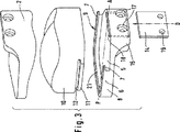
第1実施形態の下側カバープレート1および上側カバープレート2は、外側表面3,4をそれぞれ有し、これらは関連した脊椎本体に固定されることになる。これらは、好ましくは平面状である。しかしながら、よりよく固定するのに適切な表面構造を含むような別の略フラットな形態も考えられる。カバープレートは、好ましくは金属製である。
The
下側カバープレート1は、上側カバープレート2に向いた平面状の底面5を有し、これは、内側アンダーカットの上部で内向きに突出したリッジ7を形成する襟部(collar)6によって三方が囲われている。下側カバープレート1は、平面で見ると、卵形(oval)または略矩形状である。
The
下側カバープレート1の底面5および襟部6は、良好なスライド特性を持つ材料、例えばポリエチレンで形成されたプロテーゼコア10のための台座を形成している。これは、底面5と整合する平面状の下側表面を有し、端部リッジ11によって横方向および背面方向に範囲が定められ、端部リッジ11の上方には溝(groove)12が位置している。リッジ11は、リッジ7の下方にある襟部6のアンダーカットと係合する。リッジ7は、溝12と係合する。こうしてプロテーゼコア10は、下側カバープレート1からの持ち上げに抗して取り付けられる。スライド遊びが、襟部6と下側カバープレート1とコア10の端部との間に設けられる。これらの側面8,9の範囲において、そこに配置された襟部6およびリッジ7,11の枝部と溝12の枝部が互いに平行に、直線的に(rectilinearly)囲むように延びている。
The
平面で見ると、コア10は、全ての側面で、下側カバープレート1および上側カバープレート2とほぼ同じ輪郭形状を有する。特に、それは襟部6をカバーすることにより、コアの上側面によって利用可能となるスライド表面22の寸法は、襟部6の存在によって減少しない。襟部6は、コア10の高さと比較して小さくすることができる。それにもかかわらず、コアはカバープレート1,2間の空間から逃げることができない。その理由は、アンダーカットの7,11の相互作用によって、カバープレートからの持ち上げが防止されているからである。
When viewed in plan, the
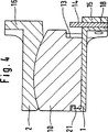
これらの腹面側の端部では、カバープレート1,2は、これらからほぼ直角に出ている取り付けフランジ15,16をそれぞれ有し、これらは脊椎本体に取り付けるためのネジ穴17を有する。下側カバープレート1のフランジ15には、制限止め板14のためのスライドガイドを形成するスロット18が設けられ、制限止め板14は変位自在に保持される。それは、図2に示すロック位置を担っており、コア10の前向き運動のための制限止めを形作る。それはまた、スロット18の中で大きく押し下げ可能であり、あるいは後者から完全に除去可能であり、これによりプロテーゼコア10を腹面方向からカバープレート間および下側カバープレートの台座へ容易に導入することが可能になる。それは2つの孔19を有し、これらはロック位置においてネジ穴17と同じ高さになる。下側カバープレート1をネジ穴17を介して脊椎本体に固定した場合、取り付けネジも孔19を貫通して、制限止め板14をロック位置で取り付ける。
At their ventral ends, the
襟部6の横方枝部は、これらのリッジ7がリッジ11およびコア10の溝12と相互作用することにより、プロテーゼコア10のためのガイド装置を形成し、後者は、AP方向(図3に示す)で開放している腹面側(図2の右側)から押し込み可能になる。襟部6の背面部分21は、取り付け制限留めとして機能し、コアがカバープレート1,2間の空間から背面方向に逃げるのを防止している。ガイド機能は、襟部6でのアンダーカットの存在と、下側カバープレート1の側面8,9およびコア10の側面のみで、襟部6の背面部分21以外でのコア10の端部とに依存している。
The lateral branches of the
上部に関して、コア10は、好ましくは、凸面状の球形関節面22を有し、これは、関節を形成するために、上側カバープレート2の下面での凹面状の球形スライド面23と相互作用する。
With respect to the upper part, the core 10 preferably has a convex spherical articulating
一方、図2に係る実施形態でのプロテーゼコア10は、実装状態で、背面側制限止め21と腹面側制限止め14との間で移動不可能に固定されている。図4は、プロテーゼコア10が、腹面側(図4での右側)で下側カバープレートより少し短くなった変形を示しており、プロテーゼコアが最も背面側位置にある場合に、腹面側端部13と制限止め14との間に隙間が残るようになっている。この実装状態で、この隙間によって、コア10はAP方向に移動可能になる。屈曲運動の場合は、上側カバープレート2は、図4から見て、下側カバープレート1に関して時計回りにわずかに旋回し、伸展運動の場合は、反対方向に移動する。もし上側カバープレート2が、スライド表面22,23によって予め決まる方向に正確に追従する場合、この旋回運動は、屈曲時に前向き(図4の右向き)および伸展時に後向きとなる並進運動と関連する。この並進運動の一部は、生理学的状態と一致しないかもしれず、不所望のストレスをもたらすかもしれない。これらのストレスは復元力を生じさせ、本発明に係るプロテーゼ設計において、上側カバープレートが下側カバープレートとは反対方向に移動するようになり、これにより不所望の運動成分を補償する。
On the other hand, the
コアおよびカバープレートの相互作用するガイド装置間で、横方向にかなり大きな隙間を残すことが可能であり、これによりこの方向で一定の相対運動が可能になる。 It is possible to leave a fairly large gap in the transverse direction between the interacting guide devices of the core and cover plate, which allows a constant relative movement in this direction.
頸部脊椎プロテーゼにおいて、AP方向での運動隙間は、好ましくは1〜4ミリメートル、より好ましくは2〜3ミリメートルのオーダーである。横方向での相対可動性を設ける場合、この範囲は2ミリメートル未満とすべきである。 In the cervical spine prosthesis, the movement gap in the AP direction is preferably on the order of 1 to 4 millimeters, more preferably 2 to 3 millimeters. This range should be less than 2 millimeters when providing relative mobility in the lateral direction.
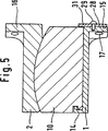
第2実施形態に関して、上記の説明は、腹面側制限止めを除いて適用される。これらの腹面側端部において、カバープレート1,2は、これらから直角に出ているフランジ15,16をそれぞれ有し、これらは脊椎本体に取り付けるためのネジ穴17を有する。下側カバープレート1のフランジ15には、制限止め板28が、2つのネジ穴17の間の中央に位置する頭付きピン29によって旋回可能に取り付けらる。スライド可能な旋回面は、取り付けフランジ15の前面によって規定され、これをスライドガイド面と称する。制限止め板は、ほぼ横向きに延びる2つの羽根部30と、これらを横断する方向に延びる舌部31を有する。それは、弾力のある金属で形成され、その羽根部30がスライドガイド面を押さえるように、予めストレスが付与されている。例えば、ネジ回しなどの回転ツールの係合に関して、それは適切な開口または凹部32を有する。それが、図6に示す実装位置に配置される場合、下側カバープレートの底面5の上には延びていない。従って、コア10は、襟部6によって形成された挿入ガイドへ妨害無く押し込むことができる。図5および図7に図示したように、それを180度回転すると、舌部31は底面5の上に突出して、コア10がガイドから腹面側に出るのを防止する制限止めを形成する。
Regarding the second embodiment, the above description is applied except for the ventral side restriction stop. At these ventral side ends, the
図6に示す実装位置では、制限止め板28は、取り付けネジの係合のためにネジ穴17をフリーにしている。図7に示すように、取り付け位置において、羽根部30は、完全または部分的にネジ穴17を覆っており、ここに配置されたネジ頭を弾性的に押圧して、ネジ穴17から外れるのを防止している。これらは開口を有し、プレストレスの状態で、図7に示したネジ頭33のキャップ上で係合することで、取り付け板が取り付け位置から外れるのを防止している。
In the mounting position shown in FIG. 6, the
図7に示すように、数ミリメータの自由スペースが、プロテーゼコア10用の制限止めとして設けられた、制限止め板28の舌部31と、それに対向するコア10の表面13との間に配置可能である。これにより、コア10は、襟部6の横部分8,9によって形成されたガイドにおいてAP方向に一定の距離だけ移動可能になる(図4の説明を参照)。もしこの運動の隙間を欲しない場合、表面13と制限止め14との間の自由スペースをゼロに減少させて、図6での場合のようになる。
As shown in FIG. 7, a few millimeters of free space can be placed between the
図8〜図12に係る第3実施形態に関して、腹面側制限止め装置を除いて、図1〜図3の説明が適用される。 Regarding the third embodiment according to FIGS. 8 to 12, the description of FIGS. 1 to 3 is applied except for the ventral surface side limit stop device.
スロット40は、下側カバープレート1の腹面側端部に沿った切り込みであり、図10のフランジ15の左半分で上から下まで完全に延びており、フランジ15の右半分では、図10に示す破線41によって範囲が定められている。スロット40に対向して、スロット42がプロテーゼコア10の下側で切り込まれており、スロット40と同一面になっている。2つのスロット40,42は、制限止め板43を受け入れるように機能し、その輪郭は、それを受け入れるようにスロット40,42によって形成されたスペースの限界とほぼ一致している。プロテーゼコア10が挿入された後、それは、図10に示すように、側方からスロット40,42の中に押し入れられる。
The
制限止め板43は、留めラグ44とともに端部に設けることが可能であり、これは、制限止め板43をスロット40,42の中に完全に挿入した後、右手側に突出して(図11参照)、制限止め板を固定するために後方に屈曲可能となる。フランジ15は、下側カバープレート1を関連する脊椎本体の上に取り付けるために使用されるネジ穴17を有する。左部分において(図10参照)、これらに位置するネジ穴17はスロット40を貫通し、これは、その箇所でフランジ15の全高を超えるように延びており、制限止め板の左側の幅広羽根部45を受け入れる。制限止め板の幅広羽根部45も同様に、ネジ穴46を有し、制限止め板43が押し入れられた場合(図9と図11)、そこに位置したネジ穴17と同一高さになる。取り付けネジがこのネジ穴に配置されると、制限止め板43は、取り付け位置から逃げることができない。
The
ネジ穴46および留めラグ44は、互いに独立して機能する取り付け装置を形成する。従って、必ずしもこれら両方とも設ける必要はない。もしネジ穴46が有る場合、留めラグ44が省略できる。もし留めラグが有る場合、制限止め板の幅広羽根部45のライン47より下の部分と、取り付けフランジ15でのスロットの対応部分とが省略できる。この場合、破線47より上に延びる制限止め板を有することで足りる(図12)。この場合、制限止め板が受入れスロット40,42から右側に逃げられないことを確保するために、留めラグ44に対応した取り付けラグ(不図示)を制限止め板43の左端部に設けることも可能である。制限止め板43は、スロット42を形成するプロテーゼコア10の一部によってカバーされているため、上向きに逃げられない。
The
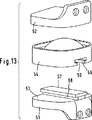
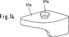
図13および図14に係る第4実施形態は、下側カバープレート1上にプロテーゼコア10用に形成された台座についての代替可能な構成を図示している。本実施形態において、プロテーゼは、下側カバープレート51と、上側カバープレート52とで構成される。下側カバープレートは、プロテーゼコア54が搭載される上側平面状の底面53を有する。このコアは、前述の実施形態において、その外周エッジによって案内されていたが、第4実施形態では、アンダーカットされた内側エッジ56を持つ凹部55を有し、内側エッジ56は、対応してアンダーカットされたエッジ58を持つ、下側カバープレートの細長い突起57と相互作用する。こうしてコア54は、第1実施形態を参照して説明したものと同じように、下側カバープレート51に対してAP方向に移動可能である。さらに、アンダーカットの相互作用は、下側カバープレートからの持ち上げから防御している。制限止め(不図示)が設けられ、これはプロテーゼコアがプレート間のスペースから背面側および腹面側に逃げるのを防止する。
The fourth embodiment according to FIGS. 13 and 14 illustrates an alternative configuration for a pedestal formed for the
下側カバープレート51は、図14に示す下側カバープレート51aによって置き換え可能であり、これは、その突起57aが細長くなく、平面視で円形である点で、下側カバープレート31と相違している。これは、プロテーゼコア54は、上側カバープレート52と垂直軸に関して回転可能に連結するようになっていて、所望のAP運動を妨害することなく突起57a周りに回転可能であることを意味する。このことは、コア54と上側カバープレート52との間のスライド表面が非球面の構成である場合にも望ましいことである。
The
Claims (19)
第2脊椎本体に連結される第2カバープレート(2,52)と、
第2カバープレート(2,52)とともに関節を形成し、第1カバープレート(1,51)の台座によって保持されるプロテーゼコア(10,54)とを備え、
台座は、コア(10,54)が腹面側から第1カバープレート(1,51)に対して移動可能となるガイド装置(7,11,12,56,57,57a)として設計され、
第1カバープレート(1,51)は、腹面側においてスライドガイド(18,29,40)を有し、スライドガイドに対して、第1カバープレート(1,51)にある制限止め(14,31,43)がロック位置と非ロック位置との間で変位可能であり、制限止め(14,31,43)は、プロテーゼコア(10,54)と第2カバープレート(2,52)との間の相対運動を干渉しないような高さを有する、特に、頸部脊椎のための椎間プロテーゼ。A first cover plate (1, 51) coupled to the first spine body;
A second cover plate (2, 52) coupled to the second spine body;
Prosthetic core (10, 54) that forms a joint with the second cover plate (2, 52) and is held by the pedestal of the first cover plate (1, 51),
The pedestal is designed as a guide device (7, 11, 12, 56, 57, 57a) that allows the core (10, 54) to move from the abdominal surface side to the first cover plate (1, 51).
The first cover plate (1, 51) has slide guides (18, 29, 40) on the abdominal surface side, and the restriction stoppers ( 14, 31) on the first cover plate (1 , 51) with respect to the slide guide. , 43) Ri displaceable der between the locked and unlocked positions, limit stop (14,31,43) is the prosthesis core (10,54) and the second cover plate (2, 52) Intervertebral prosthesis , especially for the cervical spine, having a height that does not interfere with the relative movement between.
制限止め板(28)は、制限止め板(28)のロック位置において第1カバープレートの底面(5)の上に突出し、非ロック位置において第1カバープレートの底面より下方となる舌部(31)を有する請求項1または2記載のプロテーゼ。The slide guide for the limit stop plate (28) is formed by a slide guide surface extending in a direction crossing the AP direction at the abdominal surface side end portion of the first cover plate (1), and a pivot pin protruding from the slide guide surface (29) the limit stop plate (28) is pivotably mounted,
The limit stop plate (28) protrudes above the bottom surface (5) of the first cover plate at the locked position of the limit stop plate (28) and is below the bottom surface of the first cover plate at the unlocked position (31). The prosthesis according to claim 1 or 2, wherein
第2脊椎本体に連結される第2カバープレートと、
第2カバープレートとともに関節を形成し、第1カバープレートの台座によって保持されるプロテーゼコアとを備え、特に、頸部脊椎のための椎間プロテーゼのシステムであって、
請求項1〜15のいずれかに記載のプロテーゼタイプに加えて、プロテーゼコアと第1カバープレートの間にAP可動性を有しない突合せ外側形状のタイプを備えることを特徴とするシステム。A first cover plate coupled to the first spine body;
A second cover plate coupled to the second spine body;
A prosthetic core articulating with a second cover plate and held by a pedestal of the first cover plate, in particular a system of intervertebral prostheses for the cervical spine,
In addition to the prosthesis type according to any one of claims 1 to 15, a system comprising a butt outer shape type having no AP mobility between the prosthesis core and the first cover plate.
Applications Claiming Priority (4)
| Application Number | Priority Date | Filing Date | Title |
|---|---|---|---|
| EP02005632A EP1344508B1 (en) | 2002-03-12 | 2002-03-12 | Intervertebral prosthesis especially for the cervical spine |
| EP02005630A EP1344506A1 (en) | 2002-03-12 | 2002-03-12 | Intervertebral prosthesis for the cervical spine |
| EP02005631A EP1344507A1 (en) | 2002-03-12 | 2002-03-12 | Intervertebral prosthesis for the cervical spine |
| PCT/EP2002/011524 WO2003075803A1 (en) | 2002-03-12 | 2002-10-15 | Intravertebral prosthesis |
Publications (3)
| Publication Number | Publication Date |
|---|---|
| JP2005526550A JP2005526550A (en) | 2005-09-08 |
| JP2005526550A5 JP2005526550A5 (en) | 2006-01-05 |
| JP4243197B2 true JP4243197B2 (en) | 2009-03-25 |
Family
ID=27808292
Family Applications (1)
| Application Number | Title | Priority Date | Filing Date |
|---|---|---|---|
| JP2003574081A Expired - Fee Related JP4243197B2 (en) | 2002-03-12 | 2002-10-15 | Intervertebral prosthesis |
Country Status (15)
| Country | Link |
|---|---|
| EP (1) | EP1482875B1 (en) |
| JP (1) | JP4243197B2 (en) |
| KR (1) | KR20050026696A (en) |
| CN (1) | CN100444813C (en) |
| AT (1) | ATE424788T1 (en) |
| AU (2) | AU2002346916B2 (en) |
| BR (1) | BR0215639A (en) |
| CA (1) | CA2482403C (en) |
| DE (1) | DE50213354D1 (en) |
| ES (1) | ES2322446T3 (en) |
| IL (2) | IL163649A0 (en) |
| MX (1) | MXPA04008811A (en) |
| PL (1) | PL371017A1 (en) |
| WO (1) | WO2003075803A1 (en) |
| ZA (1) | ZA200407101B (en) |
Families Citing this family (41)
| Publication number | Priority date | Publication date | Assignee | Title |
|---|---|---|---|---|
| FR2824261B1 (en) | 2001-05-04 | 2004-05-28 | Ldr Medical | INTERVERTEBRAL DISC PROSTHESIS AND IMPLEMENTATION METHOD AND TOOLS |
| US7001433B2 (en) | 2002-05-23 | 2006-02-21 | Pioneer Laboratories, Inc. | Artificial intervertebral disc device |
| US8388684B2 (en) | 2002-05-23 | 2013-03-05 | Pioneer Signal Technology, Inc. | Artificial disc device |
| US8012212B2 (en) | 2003-04-07 | 2011-09-06 | Nuvasive, Inc. | Cervical intervertebral disk prosthesis |
| DE10330698B4 (en) * | 2003-07-08 | 2005-05-25 | Aesculap Ag & Co. Kg | Intervertebral implant |
| EP1711141B1 (en) * | 2004-01-09 | 2013-03-06 | Warsaw Orthopedic, Inc. | Split spinal device and method |
| JP4996927B2 (en) | 2004-02-04 | 2012-08-08 | エル・デ・エール・メデイカル | Intervertebral disc prosthesis |
| FR2865629B1 (en) | 2004-02-04 | 2007-01-26 | Ldr Medical | INTERVERTEBRAL DISC PROSTHESIS |
| EP1570813A1 (en) * | 2004-03-05 | 2005-09-07 | Cervitech, Inc. | Cervical intervertebral disc prosthesis with anti-luxation means, and instrument |
| US7175662B2 (en) * | 2004-04-01 | 2007-02-13 | Cervitech, Inc. | Cervical intervertebral prosthesis |
| US8172855B2 (en) | 2004-11-24 | 2012-05-08 | Abdou M S | Devices and methods for inter-vertebral orthopedic device placement |
| FR2879436B1 (en) | 2004-12-22 | 2007-03-09 | Ldr Medical | INTERVERTEBRAL DISC PROSTHESIS |
| FR2887435B1 (en) * | 2005-06-24 | 2007-10-05 | Abbott Spine Sa | INTERVERTEBRAL DISC PROSTHESIS |
| FR2887762B1 (en) | 2005-06-29 | 2007-10-12 | Ldr Medical Soc Par Actions Si | INTERVERTEBRAL DISC PROSTHESIS INSERTION INSTRUMENTATION BETWEEN VERTEBRATES |
| FR2891135B1 (en) | 2005-09-23 | 2008-09-12 | Ldr Medical Sarl | INTERVERTEBRAL DISC PROSTHESIS |
| FR2893838B1 (en) | 2005-11-30 | 2008-08-08 | Ldr Medical Soc Par Actions Si | PROSTHESIS OF INTERVERTEBRAL DISC AND INSTRUMENTATION OF INSERTION OF THE PROSTHESIS BETWEEN VERTEBRATES |
| EP2063817A4 (en) | 2006-09-15 | 2012-04-18 | Pioneer Surgical Technology Inc | Joint arthroplasty devices having articulating members |
| US8715350B2 (en) | 2006-09-15 | 2014-05-06 | Pioneer Surgical Technology, Inc. | Systems and methods for securing an implant in intervertebral space |
| US8465546B2 (en) | 2007-02-16 | 2013-06-18 | Ldr Medical | Intervertebral disc prosthesis insertion assemblies |
| FR2916956B1 (en) | 2007-06-08 | 2012-12-14 | Ldr Medical | INTERSOMATIC CAGE, INTERVERTEBRAL PROSTHESIS, ANCHORING DEVICE AND IMPLANTATION INSTRUMENTATION |
| US10821003B2 (en) | 2007-06-20 | 2020-11-03 | 3Spline Sezc | Spinal osteotomy |
| US8764806B2 (en) | 2009-12-07 | 2014-07-01 | Samy Abdou | Devices and methods for minimally invasive spinal stabilization and instrumentation |
| ES2622986T3 (en) * | 2011-05-18 | 2017-07-10 | Karin Büttner-Janz | Spinal prosthetic disc |
| US8845728B1 (en) | 2011-09-23 | 2014-09-30 | Samy Abdou | Spinal fixation devices and methods of use |
| US9241807B2 (en) | 2011-12-23 | 2016-01-26 | Pioneer Surgical Technology, Inc. | Systems and methods for inserting a spinal device |
| US20130226240A1 (en) | 2012-02-22 | 2013-08-29 | Samy Abdou | Spinous process fixation devices and methods of use |
| US9198767B2 (en) | 2012-08-28 | 2015-12-01 | Samy Abdou | Devices and methods for spinal stabilization and instrumentation |
| US9320617B2 (en) | 2012-10-22 | 2016-04-26 | Cogent Spine, LLC | Devices and methods for spinal stabilization and instrumentation |
| KR101397192B1 (en) * | 2013-12-18 | 2014-05-19 | 윤홍원 | Intervertebral tentional artificial disc replacement |
| CN105105890A (en) * | 2015-08-31 | 2015-12-02 | 北京市春立正达医疗器械股份有限公司 | Cervical vertebrae inter-vertebral disc prosthesis |
| US10857003B1 (en) | 2015-10-14 | 2020-12-08 | Samy Abdou | Devices and methods for vertebral stabilization |
| CN105662661B (en) * | 2016-02-26 | 2018-02-13 | 邹德威 | Implants, Intervertebral disc fusion device and artificial intervertebral disk for spinal decompression |
| CN106236332B (en) * | 2016-08-31 | 2018-07-20 | 北京爱康宜诚医疗器材有限公司 | Intervertebral disk prosthesis |
| US10973648B1 (en) | 2016-10-25 | 2021-04-13 | Samy Abdou | Devices and methods for vertebral bone realignment |
| US10744000B1 (en) | 2016-10-25 | 2020-08-18 | Samy Abdou | Devices and methods for vertebral bone realignment |
| CA3053415A1 (en) * | 2017-02-17 | 2018-08-23 | Institut National De La Sante Et De La Recherche Medicale (Inserm) | Temporo-mandibular prosthesis |
| CN107049563B (en) * | 2017-04-19 | 2020-02-07 | 北京爱康宜诚医疗器材有限公司 | Intervertebral disc prosthesis |
| WO2019051260A1 (en) | 2017-09-08 | 2019-03-14 | Pioneer Surgical Technology, Inc. | Intervertebral implants, instruments, and methods |
| USD907771S1 (en) | 2017-10-09 | 2021-01-12 | Pioneer Surgical Technology, Inc. | Intervertebral implant |
| CN108836579B (en) * | 2018-07-06 | 2023-07-28 | 北京爱康宜诚医疗器材有限公司 | Artificial intervertebral disc prosthesis |
| US11179248B2 (en) | 2018-10-02 | 2021-11-23 | Samy Abdou | Devices and methods for spinal implantation |
Family Cites Families (9)
| Publication number | Priority date | Publication date | Assignee | Title |
|---|---|---|---|---|
| FR2659226B1 (en) | 1990-03-07 | 1992-05-29 | Jbs Sa | PROSTHESIS FOR INTERVERTEBRAL DISCS AND ITS IMPLEMENTATION INSTRUMENTS. |
| US5425773A (en) * | 1992-01-06 | 1995-06-20 | Danek Medical, Inc. | Intervertebral disk arthroplasty device |
| US5676701A (en) * | 1993-01-14 | 1997-10-14 | Smith & Nephew, Inc. | Low wear artificial spinal disc |
| FR2718635B1 (en) * | 1994-04-15 | 1996-07-05 | Axcyl Medical | Cervical prosthesis. |
| WO1999065412A1 (en) * | 1998-06-18 | 1999-12-23 | Pioneer Laboratories, Inc. | Spinal fixation system |
| DE29814174U1 (en) * | 1998-08-07 | 1999-12-16 | Howmedica Gmbh | Instruments for inserting an implant into the human spine |
| US6368350B1 (en) * | 1999-03-11 | 2002-04-09 | Sulzer Spine-Tech Inc. | Intervertebral disc prosthesis and method |
| CA2391330C (en) * | 1999-07-02 | 2008-11-18 | Spine Solutions Inc. | Intervertebral implant |
| CN2445722Y (en) * | 2000-09-26 | 2001-09-05 | 沈强 | Human cervical intervertebral disc prosthesis |
-
2002
- 2002-10-15 AT AT02782913T patent/ATE424788T1/en not_active IP Right Cessation
- 2002-10-15 CA CA2482403A patent/CA2482403C/en not_active Expired - Fee Related
- 2002-10-15 AU AU2002346916A patent/AU2002346916B2/en not_active Ceased
- 2002-10-15 JP JP2003574081A patent/JP4243197B2/en not_active Expired - Fee Related
- 2002-10-15 DE DE50213354T patent/DE50213354D1/en not_active Expired - Lifetime
- 2002-10-15 MX MXPA04008811A patent/MXPA04008811A/en active IP Right Grant
- 2002-10-15 BR BR0215639-3A patent/BR0215639A/en not_active IP Right Cessation
- 2002-10-15 IL IL16364902A patent/IL163649A0/en unknown
- 2002-10-15 WO PCT/EP2002/011524 patent/WO2003075803A1/en active Application Filing
- 2002-10-15 PL PL02371017A patent/PL371017A1/en unknown
- 2002-10-15 EP EP02782913A patent/EP1482875B1/en not_active Expired - Lifetime
- 2002-10-15 CN CNB028285107A patent/CN100444813C/en not_active Expired - Fee Related
- 2002-10-15 KR KR1020047014208A patent/KR20050026696A/en not_active Application Discontinuation
- 2002-10-15 ES ES02782913T patent/ES2322446T3/en not_active Expired - Lifetime
-
2004
- 2004-08-19 IL IL163649A patent/IL163649A/en not_active IP Right Cessation
- 2004-09-06 ZA ZA2004/07101A patent/ZA200407101B/en unknown
-
2008
- 2008-10-20 AU AU2008230006A patent/AU2008230006A1/en not_active Abandoned
Also Published As
| Publication number | Publication date |
|---|---|
| ZA200407101B (en) | 2005-08-31 |
| AU2002346916A1 (en) | 2003-09-22 |
| KR20050026696A (en) | 2005-03-15 |
| DE50213354D1 (en) | 2009-04-23 |
| EP1482875A1 (en) | 2004-12-08 |
| CN1622793A (en) | 2005-06-01 |
| IL163649A (en) | 2009-11-18 |
| CN100444813C (en) | 2008-12-24 |
| WO2003075803A1 (en) | 2003-09-18 |
| AU2008230006A1 (en) | 2008-11-13 |
| ES2322446T3 (en) | 2009-06-22 |
| BR0215639A (en) | 2004-12-21 |
| MXPA04008811A (en) | 2005-07-01 |
| ATE424788T1 (en) | 2009-03-15 |
| EP1482875B1 (en) | 2009-03-11 |
| CA2482403A1 (en) | 2003-09-18 |
| CA2482403C (en) | 2010-08-03 |
| JP2005526550A (en) | 2005-09-08 |
| PL371017A1 (en) | 2005-06-13 |
| AU2002346916B2 (en) | 2008-08-07 |
| IL163649A0 (en) | 2005-12-18 |
Similar Documents
| Publication | Publication Date | Title |
|---|---|---|
| JP4243197B2 (en) | Intervertebral prosthesis | |
| US7001432B2 (en) | Intervertebral prosthesis | |
| US7862614B2 (en) | Intervertebral prosthesis system, in particular for the cervical spine | |
| US10492919B2 (en) | Intervertebral disc prosthesis | |
| AU2009212810B2 (en) | Intervertebral Disc Prosthesis | |
| US6623526B1 (en) | Knee prosthesis | |
| US7780731B2 (en) | Intervertebral implant | |
| JP2009508615A5 (en) | ||
| KR20070115900A (en) | Cervical interverterbral prostheses | |
| EP1169980B1 (en) | A knee prosthesis | |
| KR20110060917A (en) | Implant |
Legal Events
| Date | Code | Title | Description |
|---|---|---|---|
| A521 | Request for written amendment filed |
Free format text: JAPANESE INTERMEDIATE CODE: A523 Effective date: 20051004 |
|
| A621 | Written request for application examination |
Free format text: JAPANESE INTERMEDIATE CODE: A621 Effective date: 20051004 |
|
| RD03 | Notification of appointment of power of attorney |
Free format text: JAPANESE INTERMEDIATE CODE: A7423 Effective date: 20070730 |
|
| A131 | Notification of reasons for refusal |
Free format text: JAPANESE INTERMEDIATE CODE: A131 Effective date: 20080610 |
|
| A521 | Request for written amendment filed |
Free format text: JAPANESE INTERMEDIATE CODE: A523 Effective date: 20080901 |
|
| TRDD | Decision of grant or rejection written | ||
| A01 | Written decision to grant a patent or to grant a registration (utility model) |
Free format text: JAPANESE INTERMEDIATE CODE: A01 Effective date: 20081202 |
|
| A01 | Written decision to grant a patent or to grant a registration (utility model) |
Free format text: JAPANESE INTERMEDIATE CODE: A01 |
|
| A61 | First payment of annual fees (during grant procedure) |
Free format text: JAPANESE INTERMEDIATE CODE: A61 Effective date: 20081226 |
|
| FPAY | Renewal fee payment (event date is renewal date of database) |
Free format text: PAYMENT UNTIL: 20120109 Year of fee payment: 3 |
|
| R150 | Certificate of patent or registration of utility model |
Free format text: JAPANESE INTERMEDIATE CODE: R150 |
|
| S531 | Written request for registration of change of domicile |
Free format text: JAPANESE INTERMEDIATE CODE: R313531 |
|
| FPAY | Renewal fee payment (event date is renewal date of database) |
Free format text: PAYMENT UNTIL: 20120109 Year of fee payment: 3 |
|
| R350 | Written notification of registration of transfer |
Free format text: JAPANESE INTERMEDIATE CODE: R350 |
|
| FPAY | Renewal fee payment (event date is renewal date of database) |
Free format text: PAYMENT UNTIL: 20130109 Year of fee payment: 4 |
|
| R250 | Receipt of annual fees |
Free format text: JAPANESE INTERMEDIATE CODE: R250 |
|
| R250 | Receipt of annual fees |
Free format text: JAPANESE INTERMEDIATE CODE: R250 |
|
| LAPS | Cancellation because of no payment of annual fees |