JP4240086B2 - Exhaust gas purification system for internal combustion engine - Google Patents
Exhaust gas purification system for internal combustion engine Download PDFInfo
- Publication number
- JP4240086B2 JP4240086B2 JP2006215654A JP2006215654A JP4240086B2 JP 4240086 B2 JP4240086 B2 JP 4240086B2 JP 2006215654 A JP2006215654 A JP 2006215654A JP 2006215654 A JP2006215654 A JP 2006215654A JP 4240086 B2 JP4240086 B2 JP 4240086B2
- Authority
- JP
- Japan
- Prior art keywords
- pressure egr
- temperature
- low
- egr gas
- amount
- Prior art date
- Legal status (The legal status is an assumption and is not a legal conclusion. Google has not performed a legal analysis and makes no representation as to the accuracy of the status listed.)
- Expired - Fee Related
Links
Images


Classifications
-
- F—MECHANICAL ENGINEERING; LIGHTING; HEATING; WEAPONS; BLASTING
- F01—MACHINES OR ENGINES IN GENERAL; ENGINE PLANTS IN GENERAL; STEAM ENGINES
- F01N—GAS-FLOW SILENCERS OR EXHAUST APPARATUS FOR MACHINES OR ENGINES IN GENERAL; GAS-FLOW SILENCERS OR EXHAUST APPARATUS FOR INTERNAL COMBUSTION ENGINES
- F01N13/00—Exhaust or silencing apparatus characterised by constructional features ; Exhaust or silencing apparatus, or parts thereof, having pertinent characteristics not provided for in, or of interest apart from, groups F01N1/00 - F01N5/00, F01N9/00, F01N11/00
- F01N13/009—Exhaust or silencing apparatus characterised by constructional features ; Exhaust or silencing apparatus, or parts thereof, having pertinent characteristics not provided for in, or of interest apart from, groups F01N1/00 - F01N5/00, F01N9/00, F01N11/00 having two or more separate purifying devices arranged in series
- F01N13/0097—Exhaust or silencing apparatus characterised by constructional features ; Exhaust or silencing apparatus, or parts thereof, having pertinent characteristics not provided for in, or of interest apart from, groups F01N1/00 - F01N5/00, F01N9/00, F01N11/00 having two or more separate purifying devices arranged in series the purifying devices are arranged in a single housing
-
- F—MECHANICAL ENGINEERING; LIGHTING; HEATING; WEAPONS; BLASTING
- F01—MACHINES OR ENGINES IN GENERAL; ENGINE PLANTS IN GENERAL; STEAM ENGINES
- F01N—GAS-FLOW SILENCERS OR EXHAUST APPARATUS FOR MACHINES OR ENGINES IN GENERAL; GAS-FLOW SILENCERS OR EXHAUST APPARATUS FOR INTERNAL COMBUSTION ENGINES
- F01N3/00—Exhaust or silencing apparatus having means for purifying, rendering innocuous, or otherwise treating exhaust
- F01N3/02—Exhaust or silencing apparatus having means for purifying, rendering innocuous, or otherwise treating exhaust for cooling, or for removing solid constituents of, exhaust
- F01N3/021—Exhaust or silencing apparatus having means for purifying, rendering innocuous, or otherwise treating exhaust for cooling, or for removing solid constituents of, exhaust by means of filters
- F01N3/023—Exhaust or silencing apparatus having means for purifying, rendering innocuous, or otherwise treating exhaust for cooling, or for removing solid constituents of, exhaust by means of filters using means for regenerating the filters, e.g. by burning trapped particles
- F01N3/025—Exhaust or silencing apparatus having means for purifying, rendering innocuous, or otherwise treating exhaust for cooling, or for removing solid constituents of, exhaust by means of filters using means for regenerating the filters, e.g. by burning trapped particles using fuel burner or by adding fuel to exhaust
- F01N3/0253—Exhaust or silencing apparatus having means for purifying, rendering innocuous, or otherwise treating exhaust for cooling, or for removing solid constituents of, exhaust by means of filters using means for regenerating the filters, e.g. by burning trapped particles using fuel burner or by adding fuel to exhaust adding fuel to exhaust gases
-
- F—MECHANICAL ENGINEERING; LIGHTING; HEATING; WEAPONS; BLASTING
- F01—MACHINES OR ENGINES IN GENERAL; ENGINE PLANTS IN GENERAL; STEAM ENGINES
- F01N—GAS-FLOW SILENCERS OR EXHAUST APPARATUS FOR MACHINES OR ENGINES IN GENERAL; GAS-FLOW SILENCERS OR EXHAUST APPARATUS FOR INTERNAL COMBUSTION ENGINES
- F01N3/00—Exhaust or silencing apparatus having means for purifying, rendering innocuous, or otherwise treating exhaust
- F01N3/02—Exhaust or silencing apparatus having means for purifying, rendering innocuous, or otherwise treating exhaust for cooling, or for removing solid constituents of, exhaust
- F01N3/021—Exhaust or silencing apparatus having means for purifying, rendering innocuous, or otherwise treating exhaust for cooling, or for removing solid constituents of, exhaust by means of filters
- F01N3/033—Exhaust or silencing apparatus having means for purifying, rendering innocuous, or otherwise treating exhaust for cooling, or for removing solid constituents of, exhaust by means of filters in combination with other devices
- F01N3/035—Exhaust or silencing apparatus having means for purifying, rendering innocuous, or otherwise treating exhaust for cooling, or for removing solid constituents of, exhaust by means of filters in combination with other devices with catalytic reactors, e.g. catalysed diesel particulate filters
-
- F—MECHANICAL ENGINEERING; LIGHTING; HEATING; WEAPONS; BLASTING
- F01—MACHINES OR ENGINES IN GENERAL; ENGINE PLANTS IN GENERAL; STEAM ENGINES
- F01N—GAS-FLOW SILENCERS OR EXHAUST APPARATUS FOR MACHINES OR ENGINES IN GENERAL; GAS-FLOW SILENCERS OR EXHAUST APPARATUS FOR INTERNAL COMBUSTION ENGINES
- F01N3/00—Exhaust or silencing apparatus having means for purifying, rendering innocuous, or otherwise treating exhaust
- F01N3/08—Exhaust or silencing apparatus having means for purifying, rendering innocuous, or otherwise treating exhaust for rendering innocuous
- F01N3/0807—Exhaust or silencing apparatus having means for purifying, rendering innocuous, or otherwise treating exhaust for rendering innocuous by using absorbents or adsorbents
- F01N3/0828—Exhaust or silencing apparatus having means for purifying, rendering innocuous, or otherwise treating exhaust for rendering innocuous by using absorbents or adsorbents characterised by the absorbed or adsorbed substances
- F01N3/0842—Nitrogen oxides
-
- F—MECHANICAL ENGINEERING; LIGHTING; HEATING; WEAPONS; BLASTING
- F01—MACHINES OR ENGINES IN GENERAL; ENGINE PLANTS IN GENERAL; STEAM ENGINES
- F01N—GAS-FLOW SILENCERS OR EXHAUST APPARATUS FOR MACHINES OR ENGINES IN GENERAL; GAS-FLOW SILENCERS OR EXHAUST APPARATUS FOR INTERNAL COMBUSTION ENGINES
- F01N3/00—Exhaust or silencing apparatus having means for purifying, rendering innocuous, or otherwise treating exhaust
- F01N3/08—Exhaust or silencing apparatus having means for purifying, rendering innocuous, or otherwise treating exhaust for rendering innocuous
- F01N3/0807—Exhaust or silencing apparatus having means for purifying, rendering innocuous, or otherwise treating exhaust for rendering innocuous by using absorbents or adsorbents
- F01N3/0871—Regulation of absorbents or adsorbents, e.g. purging
- F01N3/0885—Regeneration of deteriorated absorbents or adsorbents, e.g. desulfurization of NOx traps
-
- F—MECHANICAL ENGINEERING; LIGHTING; HEATING; WEAPONS; BLASTING
- F02—COMBUSTION ENGINES; HOT-GAS OR COMBUSTION-PRODUCT ENGINE PLANTS
- F02D—CONTROLLING COMBUSTION ENGINES
- F02D41/00—Electrical control of supply of combustible mixture or its constituents
- F02D41/0025—Controlling engines characterised by use of non-liquid fuels, pluralities of fuels, or non-fuel substances added to the combustible mixtures
- F02D41/0047—Controlling exhaust gas recirculation [EGR]
- F02D41/005—Controlling exhaust gas recirculation [EGR] according to engine operating conditions
- F02D41/0055—Special engine operating conditions, e.g. for regeneration of exhaust gas treatment apparatus
-
- F—MECHANICAL ENGINEERING; LIGHTING; HEATING; WEAPONS; BLASTING
- F02—COMBUSTION ENGINES; HOT-GAS OR COMBUSTION-PRODUCT ENGINE PLANTS
- F02D—CONTROLLING COMBUSTION ENGINES
- F02D41/00—Electrical control of supply of combustible mixture or its constituents
- F02D41/02—Circuit arrangements for generating control signals
- F02D41/021—Introducing corrections for particular conditions exterior to the engine
- F02D41/0235—Introducing corrections for particular conditions exterior to the engine in relation with the state of the exhaust gas treating apparatus
- F02D41/024—Introducing corrections for particular conditions exterior to the engine in relation with the state of the exhaust gas treating apparatus to increase temperature of the exhaust gas treating apparatus
- F02D41/025—Introducing corrections for particular conditions exterior to the engine in relation with the state of the exhaust gas treating apparatus to increase temperature of the exhaust gas treating apparatus by changing the composition of the exhaust gas, e.g. for exothermic reaction on exhaust gas treating apparatus
-
- F—MECHANICAL ENGINEERING; LIGHTING; HEATING; WEAPONS; BLASTING
- F02—COMBUSTION ENGINES; HOT-GAS OR COMBUSTION-PRODUCT ENGINE PLANTS
- F02M—SUPPLYING COMBUSTION ENGINES IN GENERAL WITH COMBUSTIBLE MIXTURES OR CONSTITUENTS THEREOF
- F02M26/00—Engine-pertinent apparatus for adding exhaust gases to combustion-air, main fuel or fuel-air mixture, e.g. by exhaust gas recirculation [EGR] systems
- F02M26/02—EGR systems specially adapted for supercharged engines
- F02M26/04—EGR systems specially adapted for supercharged engines with a single turbocharger
- F02M26/05—High pressure loops, i.e. wherein recirculated exhaust gas is taken out from the exhaust system upstream of the turbine and reintroduced into the intake system downstream of the compressor
-
- F—MECHANICAL ENGINEERING; LIGHTING; HEATING; WEAPONS; BLASTING
- F02—COMBUSTION ENGINES; HOT-GAS OR COMBUSTION-PRODUCT ENGINE PLANTS
- F02M—SUPPLYING COMBUSTION ENGINES IN GENERAL WITH COMBUSTIBLE MIXTURES OR CONSTITUENTS THEREOF
- F02M26/00—Engine-pertinent apparatus for adding exhaust gases to combustion-air, main fuel or fuel-air mixture, e.g. by exhaust gas recirculation [EGR] systems
- F02M26/02—EGR systems specially adapted for supercharged engines
- F02M26/04—EGR systems specially adapted for supercharged engines with a single turbocharger
- F02M26/06—Low pressure loops, i.e. wherein recirculated exhaust gas is taken out from the exhaust downstream of the turbocharger turbine and reintroduced into the intake system upstream of the compressor
-
- F—MECHANICAL ENGINEERING; LIGHTING; HEATING; WEAPONS; BLASTING
- F02—COMBUSTION ENGINES; HOT-GAS OR COMBUSTION-PRODUCT ENGINE PLANTS
- F02M—SUPPLYING COMBUSTION ENGINES IN GENERAL WITH COMBUSTIBLE MIXTURES OR CONSTITUENTS THEREOF
- F02M26/00—Engine-pertinent apparatus for adding exhaust gases to combustion-air, main fuel or fuel-air mixture, e.g. by exhaust gas recirculation [EGR] systems
- F02M26/13—Arrangement or layout of EGR passages, e.g. in relation to specific engine parts or for incorporation of accessories
- F02M26/14—Arrangement or layout of EGR passages, e.g. in relation to specific engine parts or for incorporation of accessories in relation to the exhaust system
- F02M26/15—Arrangement or layout of EGR passages, e.g. in relation to specific engine parts or for incorporation of accessories in relation to the exhaust system in relation to engine exhaust purifying apparatus
-
- F—MECHANICAL ENGINEERING; LIGHTING; HEATING; WEAPONS; BLASTING
- F02—COMBUSTION ENGINES; HOT-GAS OR COMBUSTION-PRODUCT ENGINE PLANTS
- F02D—CONTROLLING COMBUSTION ENGINES
- F02D41/00—Electrical control of supply of combustible mixture or its constituents
- F02D41/0025—Controlling engines characterised by use of non-liquid fuels, pluralities of fuels, or non-fuel substances added to the combustible mixtures
- F02D41/0047—Controlling exhaust gas recirculation [EGR]
- F02D41/0065—Specific aspects of external EGR control
- F02D2041/0067—Determining the EGR temperature
-
- F—MECHANICAL ENGINEERING; LIGHTING; HEATING; WEAPONS; BLASTING
- F02—COMBUSTION ENGINES; HOT-GAS OR COMBUSTION-PRODUCT ENGINE PLANTS
- F02D—CONTROLLING COMBUSTION ENGINES
- F02D41/00—Electrical control of supply of combustible mixture or its constituents
- F02D41/02—Circuit arrangements for generating control signals
- F02D41/021—Introducing corrections for particular conditions exterior to the engine
- F02D41/0235—Introducing corrections for particular conditions exterior to the engine in relation with the state of the exhaust gas treating apparatus
- F02D2041/0265—Introducing corrections for particular conditions exterior to the engine in relation with the state of the exhaust gas treating apparatus to decrease temperature of the exhaust gas treating apparatus
-
- F—MECHANICAL ENGINEERING; LIGHTING; HEATING; WEAPONS; BLASTING
- F02—COMBUSTION ENGINES; HOT-GAS OR COMBUSTION-PRODUCT ENGINE PLANTS
- F02D—CONTROLLING COMBUSTION ENGINES
- F02D41/00—Electrical control of supply of combustible mixture or its constituents
- F02D41/0025—Controlling engines characterised by use of non-liquid fuels, pluralities of fuels, or non-fuel substances added to the combustible mixtures
- F02D41/0047—Controlling exhaust gas recirculation [EGR]
- F02D41/0065—Specific aspects of external EGR control
-
- F—MECHANICAL ENGINEERING; LIGHTING; HEATING; WEAPONS; BLASTING
- F02—COMBUSTION ENGINES; HOT-GAS OR COMBUSTION-PRODUCT ENGINE PLANTS
- F02D—CONTROLLING COMBUSTION ENGINES
- F02D41/00—Electrical control of supply of combustible mixture or its constituents
- F02D41/02—Circuit arrangements for generating control signals
- F02D41/021—Introducing corrections for particular conditions exterior to the engine
- F02D41/0235—Introducing corrections for particular conditions exterior to the engine in relation with the state of the exhaust gas treating apparatus
- F02D41/027—Introducing corrections for particular conditions exterior to the engine in relation with the state of the exhaust gas treating apparatus to purge or regenerate the exhaust gas treating apparatus
-
- F—MECHANICAL ENGINEERING; LIGHTING; HEATING; WEAPONS; BLASTING
- F02—COMBUSTION ENGINES; HOT-GAS OR COMBUSTION-PRODUCT ENGINE PLANTS
- F02D—CONTROLLING COMBUSTION ENGINES
- F02D41/00—Electrical control of supply of combustible mixture or its constituents
- F02D41/02—Circuit arrangements for generating control signals
- F02D41/14—Introducing closed-loop corrections
- F02D41/1438—Introducing closed-loop corrections using means for determining characteristics of the combustion gases; Sensors therefor
- F02D41/1444—Introducing closed-loop corrections using means for determining characteristics of the combustion gases; Sensors therefor characterised by the characteristics of the combustion gases
- F02D41/1446—Introducing closed-loop corrections using means for determining characteristics of the combustion gases; Sensors therefor characterised by the characteristics of the combustion gases the characteristics being exhaust temperatures
-
- F—MECHANICAL ENGINEERING; LIGHTING; HEATING; WEAPONS; BLASTING
- F02—COMBUSTION ENGINES; HOT-GAS OR COMBUSTION-PRODUCT ENGINE PLANTS
- F02D—CONTROLLING COMBUSTION ENGINES
- F02D9/00—Controlling engines by throttling air or fuel-and-air induction conduits or exhaust conduits
- F02D9/04—Controlling engines by throttling air or fuel-and-air induction conduits or exhaust conduits concerning exhaust conduits
-
- F—MECHANICAL ENGINEERING; LIGHTING; HEATING; WEAPONS; BLASTING
- F02—COMBUSTION ENGINES; HOT-GAS OR COMBUSTION-PRODUCT ENGINE PLANTS
- F02M—SUPPLYING COMBUSTION ENGINES IN GENERAL WITH COMBUSTIBLE MIXTURES OR CONSTITUENTS THEREOF
- F02M26/00—Engine-pertinent apparatus for adding exhaust gases to combustion-air, main fuel or fuel-air mixture, e.g. by exhaust gas recirculation [EGR] systems
- F02M2026/001—Arrangements; Control features; Details
- F02M2026/004—EGR valve controlled by a temperature signal or an air/fuel ratio (lambda) signal
-
- F—MECHANICAL ENGINEERING; LIGHTING; HEATING; WEAPONS; BLASTING
- F02—COMBUSTION ENGINES; HOT-GAS OR COMBUSTION-PRODUCT ENGINE PLANTS
- F02M—SUPPLYING COMBUSTION ENGINES IN GENERAL WITH COMBUSTIBLE MIXTURES OR CONSTITUENTS THEREOF
- F02M26/00—Engine-pertinent apparatus for adding exhaust gases to combustion-air, main fuel or fuel-air mixture, e.g. by exhaust gas recirculation [EGR] systems
- F02M26/13—Arrangement or layout of EGR passages, e.g. in relation to specific engine parts or for incorporation of accessories
- F02M26/22—Arrangement or layout of EGR passages, e.g. in relation to specific engine parts or for incorporation of accessories with coolers in the recirculation passage
- F02M26/23—Layout, e.g. schematics
-
- F—MECHANICAL ENGINEERING; LIGHTING; HEATING; WEAPONS; BLASTING
- F02—COMBUSTION ENGINES; HOT-GAS OR COMBUSTION-PRODUCT ENGINE PLANTS
- F02M—SUPPLYING COMBUSTION ENGINES IN GENERAL WITH COMBUSTIBLE MIXTURES OR CONSTITUENTS THEREOF
- F02M26/00—Engine-pertinent apparatus for adding exhaust gases to combustion-air, main fuel or fuel-air mixture, e.g. by exhaust gas recirculation [EGR] systems
- F02M26/13—Arrangement or layout of EGR passages, e.g. in relation to specific engine parts or for incorporation of accessories
- F02M26/38—Arrangement or layout of EGR passages, e.g. in relation to specific engine parts or for incorporation of accessories with two or more EGR valves disposed in parallel
-
- Y—GENERAL TAGGING OF NEW TECHNOLOGICAL DEVELOPMENTS; GENERAL TAGGING OF CROSS-SECTIONAL TECHNOLOGIES SPANNING OVER SEVERAL SECTIONS OF THE IPC; TECHNICAL SUBJECTS COVERED BY FORMER USPC CROSS-REFERENCE ART COLLECTIONS [XRACs] AND DIGESTS
- Y02—TECHNOLOGIES OR APPLICATIONS FOR MITIGATION OR ADAPTATION AGAINST CLIMATE CHANGE
- Y02T—CLIMATE CHANGE MITIGATION TECHNOLOGIES RELATED TO TRANSPORTATION
- Y02T10/00—Road transport of goods or passengers
- Y02T10/10—Internal combustion engine [ICE] based vehicles
- Y02T10/12—Improving ICE efficiencies
-
- Y—GENERAL TAGGING OF NEW TECHNOLOGICAL DEVELOPMENTS; GENERAL TAGGING OF CROSS-SECTIONAL TECHNOLOGIES SPANNING OVER SEVERAL SECTIONS OF THE IPC; TECHNICAL SUBJECTS COVERED BY FORMER USPC CROSS-REFERENCE ART COLLECTIONS [XRACs] AND DIGESTS
- Y02—TECHNOLOGIES OR APPLICATIONS FOR MITIGATION OR ADAPTATION AGAINST CLIMATE CHANGE
- Y02T—CLIMATE CHANGE MITIGATION TECHNOLOGIES RELATED TO TRANSPORTATION
- Y02T10/00—Road transport of goods or passengers
- Y02T10/10—Internal combustion engine [ICE] based vehicles
- Y02T10/40—Engine management systems
Description
本発明は、内燃機関の排気浄化システムに関する。 The present invention relates to an exhaust gas purification system for an internal combustion engine.
内燃機関における燃焼過程で発生した粒子状物質(以下、「PM」という)を捕集するパティキュレートフィルタ(以下、「フィルタ」という)や、窒素酸化物(以下、「NOx」という)を吸蔵・還元する吸蔵還元型NOx触媒(以下、「NOx触媒」という)等の排気浄化装置が知られている。 Particulate matter (hereinafter referred to as “filter”) that collects particulate matter (hereinafter referred to as “PM”) generated during the combustion process in an internal combustion engine and nitrogen oxide (hereinafter referred to as “NOx”) are occluded / An exhaust purification device such as a NOx storage reduction catalyst (hereinafter referred to as “NOx catalyst”) for reduction is known.
フィルタには、フィルタの使用に伴って排気中から捕集されたPMが堆積していく。フィルタに多量のPMが堆積すると、フィルタにおける圧力損失が増大するため、適宜フィルタに堆積したPMを酸化させてフィルタから除去する必要がある。例えば、フィルタを強制的に昇温する昇温処理を実施することでフィルタに堆積したPMを酸化・除去する技術が知られている。 PM collected from the exhaust gas as the filter is used accumulates on the filter. When a large amount of PM accumulates on the filter, the pressure loss in the filter increases. Therefore, it is necessary to appropriately oxidize the PM deposited on the filter and remove it from the filter. For example, a technique for oxidizing and removing PM deposited on a filter by performing a temperature raising process for forcibly raising the temperature of the filter is known.
昇温処理としては、トルクを発生させるための主噴射とは別に副噴射を行うことで排気の温度を上昇させることによってフィルタの温度を上昇させる方法や、フィルタに酸化触媒を担持させたりフィルタの前段に酸化触媒を配置したりするとともに排気中に燃料等の還元剤を直接添加することで、この還元剤が酸化触媒において酸化還元反応する際の反応熱によってフィルタに流入する排気の温度を上昇させてフィルタの温度を上昇させる方法等を例示できる。 The temperature raising process includes a method of raising the temperature of the exhaust gas by raising the temperature of the exhaust gas by performing sub-injection separately from the main injection for generating torque, or carrying an oxidation catalyst on the filter, By placing an oxidation catalyst in the front stage and adding a reducing agent such as fuel directly into the exhaust, the temperature of the exhaust gas flowing into the filter is raised by the reaction heat when this reducing agent undergoes an oxidation-reduction reaction in the oxidation catalyst. And a method for raising the temperature of the filter.
NOx触媒は、排気中のNOxを吸蔵するメカニズムと同様のメカニズムによって、排気中の硫黄酸化物(以下、「SOx」という)を吸蔵する性質がある。NOx触媒にSOxが吸蔵されると、NOx触媒のNOx吸蔵能力が低下するため、適宜NOx触媒に吸蔵されたSOxをNOx触媒から除去する必要がある。フィルタに堆積したPMを酸化させる場合と同様に、NOx触媒を強制的に昇温することで、NOx触媒からのSOxを除去する技術が知られている。 The NOx catalyst has a property of storing sulfur oxide (hereinafter referred to as “SOx”) in the exhaust gas by a mechanism similar to that for storing NOx in the exhaust gas. When SOx is occluded in the NOx catalyst, the NOx occlusion capacity of the NOx catalyst is reduced. Therefore, it is necessary to appropriately remove the SOx occluded in the NOx catalyst from the NOx catalyst. Similar to the case of oxidizing PM deposited on a filter, a technique for removing SOx from the NOx catalyst by forcibly raising the temperature of the NOx catalyst is known.
また、内燃機関における燃焼過程で発生するNOxの量を低減する技術として、排気の一部を内燃機関の燃焼室に再循環させる技術(以下、「EGR」という)が知られている。 As a technique for reducing the amount of NOx generated in the combustion process in the internal combustion engine, a technique for recirculating a part of the exhaust gas to the combustion chamber of the internal combustion engine (hereinafter referred to as “EGR”) is known.
近年では、このEGRをより広い運転領域で実施可能にする技術として、ターボチャージャのタービンより上流の排気通路とコンプレッサより下流の吸気通路とを接続する高圧EGR通路を介してEGRを行う高圧EGR装置と、タービンより下流の排気通路とコンプレッサより上流の吸気通路とを接続する低圧EGR通路を介してEGRを行う低圧EGR装置とを備え、内燃機関の運転状態に応じて高圧EGR装置と低圧EGR装置を切り替えて、又は、双方を併用してEGRを行う技術が開発されている(例えば特許文献1を参照)。
フィルタやNOx触媒に対して昇温処理を実施した場合、高圧EGR通路を介して内燃機関に再循環される排気(以下、「高圧EGRガス」という)や低圧EGR通路を介して内燃機関に再循環される排気(以下、「低圧EGRガス」という)の温度が過度に高温になる場合がある。 When the temperature raising process is performed on the filter or the NOx catalyst, the exhaust gas is recirculated to the internal combustion engine through the high pressure EGR passage (hereinafter referred to as “high pressure EGR gas”) or recirculated to the internal combustion engine through the low pressure EGR passage. There are cases where the temperature of the exhaust gas to be circulated (hereinafter referred to as “low pressure EGR gas”) becomes excessively high.
例えば、昇温処理として副噴射を行った場合、燃焼室の温度が高くなるため、燃焼室周辺のエンジンヘッド等の機関部材の温度が高くなる。そのため、高圧EGR通路が内燃機関の排気マニホールドと吸気マニホールドとを接続するように設けられ、高圧EGR通路がエンジンヘッドに近接している場合、エンジンヘッドが高温になると高圧EGR通路の温度が高くなる。そのため、高圧EGRガスの冷却が十分に行われなくなり、高圧EGRガスの温度が高温になる。また、副噴射を行った場合、内燃機関から排出される排気の温度が高くなるため、高圧EGRガスの温度や低圧EGRガスの温度が高くなる傾向がある。 For example, when the sub-injection is performed as the temperature raising process, the temperature of the combustion chamber increases, so the temperature of the engine member such as the engine head around the combustion chamber increases. Therefore, when the high pressure EGR passage is provided so as to connect the exhaust manifold and the intake manifold of the internal combustion engine and the high pressure EGR passage is close to the engine head, the temperature of the high pressure EGR passage increases when the engine head becomes hot. . Therefore, the high pressure EGR gas is not sufficiently cooled, and the temperature of the high pressure EGR gas becomes high. In addition, when the sub-injection is performed, the temperature of the exhaust gas discharged from the internal combustion engine increases, and therefore the temperature of the high-pressure EGR gas and the temperature of the low-pressure EGR gas tend to increase.
また、昇温処理によってフィルタに堆積したPMを酸化させる処理(以下、「フィルタ再生処理」という)の実行中は、PMの酸化反応に伴う反応熱によってフィルタが高温になる。そのため、フィルタを通過する際に排気が加熱され、フィルタから排出される排気の温度が高くなる場合がある。従って、低圧EGR通路がフィルタやNOx触媒等の排気浄化装置より下流の排気通路から分岐して吸気通路に接続するように設けられる場合、フィルタ再生処理中は高温の排気が低圧EGR通路に流入することになる。 Further, during the process of oxidizing the PM deposited on the filter by the temperature raising process (hereinafter referred to as “filter regeneration process”), the filter becomes high temperature due to the reaction heat accompanying the PM oxidation reaction. Therefore, the exhaust gas is heated when passing through the filter, and the temperature of the exhaust gas exhausted from the filter may increase. Therefore, when the low pressure EGR passage is provided so as to be branched from the exhaust passage downstream of the exhaust purification device such as a filter or NOx catalyst and connected to the intake passage, the high temperature exhaust gas flows into the low pressure EGR passage during the filter regeneration process. It will be.
また、昇温処理によってNOx触媒に吸蔵されたSOxを放出させる処理(以下、「硫黄被毒回復処理」という)が実施されている場合、或いは硫黄被毒回復処理実施後に通常の運転状態に戻った場合にも、昇温処理に伴ってエンジンヘッドや排気の温度が高温になるため、高圧EGRガスが高温になる可能性もある。 In addition, when a process for releasing SOx stored in the NOx catalyst by the temperature raising process (hereinafter referred to as “sulfur poisoning recovery process”) is performed, or after the sulfur poisoning recovery process is performed, the normal operation state is restored. Also in this case, the temperature of the engine head and the exhaust gas becomes high with the temperature raising process, so that the high pressure EGR gas may become high temperature.
高圧EGRガスが高温になった場合、燃焼室に吸入されるガスの温度が高くなるため、燃焼過程でのスモークやNOxの発生量が増大する虞がある。また、高圧EGR通路を流れる排気の量を調節する流量調節弁の動作に不具合が発生する可能性もある。 When the high-pressure EGR gas becomes high in temperature, the temperature of the gas sucked into the combustion chamber increases, and there is a risk that the amount of smoke and NOx generated during the combustion process increases. In addition, a malfunction may occur in the operation of the flow rate control valve that adjusts the amount of exhaust gas flowing through the high pressure EGR passage.
また、低圧EGRガスが高温になった場合、コンプレッサに流入するガスの温度が高温になるため、コンプレッサに不具合が発生する虞がある。また、低圧EGR通路を流れる排気の量を調節する流量調節弁の動作に不具合が発生する可能性もある。 Further, when the low-pressure EGR gas becomes high temperature, the temperature of the gas flowing into the compressor becomes high temperature, which may cause a problem in the compressor. There is also a possibility that a malfunction may occur in the operation of the flow rate adjusting valve that adjusts the amount of exhaust gas flowing through the low pressure EGR passage.
これに対して、昇温処理やフィルタ再生処理が行われている期間中は、高圧EGRガス量や低圧EGRガス量を減少させ、昇温処理が終了した時点で高圧EGRガス量や低圧EGRガス量を元に戻すようにすることが考えられる。 On the other hand, during the period in which the temperature raising process and the filter regeneration process are performed, the high pressure EGR gas amount and the low pressure EGR gas amount are decreased, and when the temperature raising process is completed, the high pressure EGR gas amount and the low pressure EGR gas are reduced. It is conceivable to restore the amount.
しかし、フィルタやNOx触媒等の排気浄化装置やエンジンヘッド等の機関部材が有する熱容量のために、昇温処理の終了後においても、暫くの間はエンジンヘッドや排気浄化装置の高温状態が持続する。 However, due to the heat capacity of the exhaust purification device such as the filter and the NOx catalyst and the engine member such as the engine head, the high temperature state of the engine head and the exhaust purification device continues for a while even after the temperature raising process is completed. .
例えば、排気浄化装置としてフィルタを備えた排気浄化システムにおいてフィルタ再生処理が行われた場合、フィルタ再生処理の実行終了後にフィルタの温度が通常時(フィルタ再生処理が実施される前の時点)におけるフィルタの温度に戻るまでには時間的な遅れが存在する。従って、フィルタ再生処理の実行終了後においても、この時間遅れに相当する期間はフィルタから流出する排気の温度が高温になる。従って、この時低圧EGRを行えば、高温の低圧EGRガスが低圧EGR通路を通過することになる。 For example, when filter regeneration processing is performed in an exhaust purification system that includes a filter as an exhaust purification device, the filter temperature is normal (after the filter regeneration processing is performed) after the completion of the filter regeneration processing. There is a time delay before returning to the temperature. Therefore, even after the completion of the filter regeneration process, the temperature of the exhaust gas flowing out from the filter becomes high during the period corresponding to this time delay. Therefore, if low pressure EGR is performed at this time, high temperature low pressure EGR gas passes through the low pressure EGR passage.
また、昇温処理として副噴射が行われた場合についても、副噴射の実行によって高温に
なった機関部材の温度が昇温処理の実行終了後に通常時(副噴射が行われていない時)における機関部材の温度に戻るまでには時間的な遅れが存在する。そのため、機関部材の高温状態は昇温処理の実行終了後暫くの間持続する。従って、昇温処理の実行終了後であっても、この時間遅れに相当する期間に高圧EGRを行えば、高温の高圧EGRガスが高圧EGR通路を流れることになる。
Further, even when the sub-injection is performed as the temperature raising process, the temperature of the engine member that has become high due to the execution of the sub-injection is normal (when the sub-injection is not performed) after the temperature raising process is completed. There is a time delay before returning to the temperature of the engine member. Therefore, the high temperature state of the engine member is maintained for a while after the completion of the temperature raising process. Accordingly, even after the completion of the temperature raising process, if the high pressure EGR is performed during the period corresponding to this time delay, the high temperature high pressure EGR gas flows through the high pressure EGR passage.
このように、高圧EGR通路を流れる排気の温度や低圧EGR通路に流入する排気の温度も、昇温処理の終了後暫くの間は高温の状態が持続すると考えられる。そのため、昇温処理が終了した時点で高圧EGRガス量や低圧EGRガス量の減量が解除された場合、上記の時間遅れに相当する期間において、依然として高温状態にある排気が通常時(昇温処理を実施していない時)と同等のガス量で高圧EGR通路や低圧EGR通路を流れることになる。 Thus, the temperature of the exhaust gas flowing through the high-pressure EGR passage and the temperature of the exhaust gas flowing into the low-pressure EGR passage are considered to remain at a high temperature for a while after the temperature raising process is completed. Therefore, when the reduction in the high pressure EGR gas amount or the low pressure EGR gas amount is canceled at the time when the temperature raising process is completed, the exhaust gas that is still in the high temperature state is normal (temperature raising process) during the period corresponding to the above time delay. The gas flows in the high-pressure EGR passage and the low-pressure EGR passage with the same gas amount as when the operation is not performed.
この場合、高圧EGRガスの温度や低圧EGRガスの温度が過度に高温になり、スモークやNOxの発生量が増大したり、高圧EGR通路や低圧EGR通路に設けられた流量調節弁やコンプレッサのインペラ等に不具合が発生したりする虞があった。 In this case, the temperature of the high-pressure EGR gas or the low-pressure EGR gas becomes excessively high, the amount of smoke or NOx generated increases, the flow control valve provided in the high-pressure EGR passage or the low-pressure EGR passage, or the compressor impeller. There is a risk that problems may occur.
本発明はこのような問題点に鑑みてなされたものであり、EGR通路を介して排気の再循環を行う排気浄化システムにおいて、排気浄化装置に対して昇温処理が行われた時に高温の排気によって吸気系やEGR系に不具合が生じることを抑制する技術を提供することを目的とする。 The present invention has been made in view of such problems, and in an exhaust purification system that recirculates exhaust gas through an EGR passage, exhaust gas having a high temperature when a temperature raising process is performed on the exhaust purification device. It aims at providing the technique which suppresses that a malfunction arises in an intake system or an EGR system by.
上記目的を達成するための本発明に係る内燃機関の排気浄化システムは、内燃機関の排気通路と前記内燃機関の吸気通路とを接続するEGR通路と、前記内燃機関の運転状態に応じて前記EGR通路を介して前記内燃機関に再循環されるEGRガスの基本量を決定するEGRガス量決定手段と、前記排気通路に設けられた排気浄化装置と、前記排気浄化装置の温度を昇温させる昇温処理を行う昇温手段と、EGRガスの温度が所定の基準温度を超えているか否かを判定する判定手段と、前記昇温処理の実行終了後において、EGRガスの温度が前記基準温度を超えていると前記判定手段によって判定される期間中は、EGRガスの量を前記EGRガス量決定手段によって決定される前記EGRガスの基本量(以下「基本EGRガス量」という)より減少させる補正手段と、を備えることを特徴とする。 In order to achieve the above object, an exhaust gas purification system for an internal combustion engine according to the present invention comprises an EGR passage connecting an exhaust passage of the internal combustion engine and an intake passage of the internal combustion engine, and the EGR according to the operating state of the internal combustion engine. EGR gas amount determining means for determining a basic amount of EGR gas recirculated to the internal combustion engine through a passage, an exhaust purification device provided in the exhaust passage, and a temperature rise for raising the temperature of the exhaust purification device A temperature raising means for performing a temperature treatment, a judgment means for judging whether or not the temperature of the EGR gas exceeds a predetermined reference temperature, and after the completion of the temperature raising treatment, the temperature of the EGR gas becomes equal to the reference temperature. During a period in which the determination means determines that the amount exceeds the EGR gas amount, the EGR gas amount is determined by the EGR gas amount determination means (hereinafter referred to as “basic EGR gas amount”). It characterized in that it comprises a correcting means further be reduced.
この構成によれば、昇温処理の実行終了後において、EGRガスの温度が所定の基準温度を超えていると判定される期間中は、EGRガス量は基本EGRガス量より減少させられる。従って、昇温処理の実施に起因してEGRガスの温度が高温になり昇温処理の終了後においてもEGRガスの温度が基準温度を超える高温状態が持続している期間中において、高温の排気がEGR通路を介して内燃機関に大量に再循環されることが抑制される。 According to this configuration, the EGR gas amount is decreased from the basic EGR gas amount during a period in which it is determined that the temperature of the EGR gas exceeds the predetermined reference temperature after the temperature raising process is completed. Accordingly, during the period in which the temperature of the EGR gas becomes high due to the execution of the temperature raising process and the high temperature state in which the temperature of the EGR gas exceeds the reference temperature continues even after the temperature raising process is finished, Is largely recirculated to the internal combustion engine via the EGR passage.
これにより、昇温処理の実行終了後においてEGR系(例えばEGR通路に設けられEGRガスの流量を調節する弁やEGRガスを冷却するEGRクーラ等)や吸気系(例えばターボチャージャのコンプレッサやインタークーラ等)に不具合が発生したりスモークやNOxの発生量が増大することを抑制できる。 Thereby, after completion of the temperature raising process, an EGR system (for example, a valve provided in the EGR passage for adjusting the flow rate of EGR gas, an EGR cooler for cooling the EGR gas, etc.) or an intake system (for example, a turbocharger compressor or intercooler). Etc.) and the generation of smoke and NOx can be suppressed from increasing.
ここで、基準温度は、吸気系や排気エミッションについて上記のような種々の不具合を発生させることがないEGRガスの温度の上限値に基づいて予め定められる温度である。例えば、該上限値より所定の安全マージンを差し引いた温度として定められる。 Here, the reference temperature is a temperature determined in advance based on the upper limit value of the temperature of the EGR gas that does not cause the above-described various problems in the intake system and the exhaust emission. For example, the temperature is determined by subtracting a predetermined safety margin from the upper limit value.
また、判定手段は、EGRガスの温度が基準温度を超えているか否かを判定可能であれ
ばどのようなものであっても良い。例えば、EGRガス温度の絶対値を推定或いは検出し、基準温度との比較するものを例示できる。
Further, the determination means may be anything as long as it can determine whether or not the temperature of the EGR gas exceeds the reference temperature. For example, the absolute value of EGR gas temperature is estimated or detected and compared with a reference temperature.
また、EGRガス温度が予め定められた複数の温度領域のうちのどの温度領域に属しているかを推定するものであっても良い。予め定められた温度領域とは、例えば、上記のような不具合を発生させる虞のあるEGRガス温度の領域(以下、「高温領域」という)、昇温処理を実施していない時のEGRガス温度の領域(以下、「通常領域」という)、といったように、予め実験等により定められた温度領域である。この場合、基準温度は高温領域と通常領域との境界温度として定めることができる。 Further, it may be estimated which temperature region the EGR gas temperature belongs to among a plurality of predetermined temperature regions. The predetermined temperature range is, for example, an EGR gas temperature range (hereinafter referred to as “high temperature range”) that may cause the above-described problems, and an EGR gas temperature when the temperature raising process is not performed. The temperature range is determined in advance by experiments or the like, such as the above-described region (hereinafter referred to as “normal region”). In this case, the reference temperature can be determined as a boundary temperature between the high temperature region and the normal region.
本発明は、内燃機関の吸気通路にコンプレッサを有し、且つ内燃機関の排気通路にタービンを有するターボチャージャと、タービンより下流の排気通路に設けられた排気浄化装置と、排気浄化装置より下流の排気通路とコンプレッサより上流の吸気通路とを接続する低圧EGR通路と、を備えた内燃機関の排気浄化システムに適用することができる。 The present invention includes a turbocharger having a compressor in an intake passage of an internal combustion engine and a turbine in an exhaust passage of the internal combustion engine, an exhaust purification device provided in an exhaust passage downstream of the turbine, and a downstream of the exhaust purification device. The present invention can be applied to an exhaust gas purification system for an internal combustion engine including a low pressure EGR passage that connects an exhaust passage and an intake passage upstream of a compressor.
この場合、判定手段は、低圧EGR通路を介して内燃機関に再循環される低圧EGRガスの温度が基準温度を超えているか否かを判定し、補正手段は、昇温処理の終了後において、低圧EGRガスの温度が基準温度を超えていると判定手段によって判定される期間中は、EGRガス量決定手段によって決定される低圧EGRガスの基本量より低圧EGRガスの量を減少させる。 In this case, the determination means determines whether or not the temperature of the low-pressure EGR gas recirculated to the internal combustion engine via the low-pressure EGR passage exceeds the reference temperature, and the correction means During the period in which the determination unit determines that the temperature of the low-pressure EGR gas exceeds the reference temperature, the amount of the low-pressure EGR gas is decreased from the basic amount of the low-pressure EGR gas determined by the EGR gas amount determination unit.
すなわち、昇温処理の実施に起因して低圧EGRガスが高温になり、昇温処理の終了後においても低圧EGRガスの高温状態が持続している期間中は、補正手段によって低圧EGRガス量が減少させられることになる。その結果、高温の排気が低圧EGR通路を介して大量に再循環されることが抑制される。 That is, the low-pressure EGR gas becomes high due to the temperature raising process, and the amount of the low-pressure EGR gas is reduced by the correction means during the period in which the high-pressure state of the low-pressure EGR gas continues even after the temperature raising process is completed. Will be reduced. As a result, a large amount of high-temperature exhaust gas is suppressed from being recirculated through the low-pressure EGR passage.
これにより、低圧EGRガス量を調節する流量調節弁や低圧EGRガスを冷却するEGRクーラ等の動作不良や、ターボチャージャのコンプレッサに流入するガスの温度が過剰に高温になることによるターボチャージャの動作不良等の不具合の発生を抑制することができる。 Due to this, the malfunction of the flow control valve for adjusting the low pressure EGR gas amount, the EGR cooler for cooling the low pressure EGR gas, or the operation of the turbocharger due to the excessively high temperature of the gas flowing into the turbocharger compressor. Occurrence of defects such as defects can be suppressed.
本発明は、内燃機関の吸気通路にコンプレッサを有し、且つ内燃機関の排気通路にタービンを有するターボチャージャと、タービンより上流の排気通路とコンプレッサより下流の吸気通路とを接続する高圧EGR通路と、を備えた内燃機関の排気浄化システムに適用することができる。 The present invention includes a turbocharger having a compressor in an intake passage of an internal combustion engine and a turbine in an exhaust passage of the internal combustion engine, and a high-pressure EGR passage connecting an exhaust passage upstream of the turbine and an intake passage downstream of the compressor. The present invention can be applied to an exhaust gas purification system for an internal combustion engine.
この場合、判定手段は、高圧EGR通路を介して内燃機関に再循環される高圧EGRガスの温度が基準温度を超えているか否かを判定し、補正手段は、昇温処理の終了後において、高圧EGRガスの温度が基準温度を超えていると判定手段によって判定される期間中、EGRガス量決定手段によって決定される高圧EGRガスの基本量より高圧EGRガス量を減少させる。 In this case, the determination means determines whether or not the temperature of the high-pressure EGR gas recirculated to the internal combustion engine via the high-pressure EGR passage exceeds the reference temperature, and the correction means During the period in which the determination unit determines that the temperature of the high-pressure EGR gas exceeds the reference temperature, the high-pressure EGR gas amount is decreased from the basic amount of the high-pressure EGR gas determined by the EGR gas amount determination unit.
すなわち、昇温処理の実施に起因して高圧EGRガスが高温になり、昇温処理の終了後においても高圧EGRガスの高温状態が持続している期間中は、補正手段によって高圧EGRガス量が減少させられることになる。その結果、高温の排気が高圧EGR通路を介して大量に再循環されることが抑制される。 That is, during the period when the high pressure EGR gas becomes high temperature due to the execution of the temperature raising process and the high temperature EGR gas remains high even after the temperature raising process is finished, the amount of the high pressure EGR gas is increased by the correcting means. Will be reduced. As a result, a large amount of high-temperature exhaust gas is suppressed from being recirculated through the high-pressure EGR passage.
これにより、高圧EGRガス量を調節する流量調節弁や高圧EGRガスを冷却するEGRクーラ等の動作不良等の不具合の発生を抑制することができる。 Thereby, generation | occurrence | production of malfunctions, such as malfunctioning, such as a flow control valve which adjusts the amount of high-pressure EGR gas, and an EGR cooler which cools high-pressure EGR gas, can be controlled.
本発明は、低圧EGR通路及び高圧EGR通路を併設し、内燃機関の運転状態に応じて低圧EGR通路と高圧EGR通路とを切り替えて、或いは併用して内燃機関に排気を再循環させるEGR手段を備えた内燃機関の排気浄化システムに適用することもできる。 The present invention provides an EGR means for recirculating exhaust gas to the internal combustion engine by providing a low pressure EGR passage and a high pressure EGR passage, and switching the low pressure EGR passage and the high pressure EGR passage according to the operating state of the internal combustion engine or using them together. The present invention can also be applied to an exhaust gas purification system for an internal combustion engine provided.
このような排気浄化システムでは、EGR手段は、内燃機関の運転状態を、高圧EGR通路のみを用いて排気の再循環を行う運転状態の領域(以下「高圧EGR領域」という)と、高圧EGR通路及び低圧EGR通路を併用して排気の再循環を行う運転状態の領域(以下「混合EGR領域」という)と、低圧EGR通路のみを用いて排気の再循環を行う運転状態の領域(以下「低圧EGR領域」という)と、排気の再循環を行わない運転状態の領域と、に分け、内燃機関の運転状態が属している領域に応じて、低圧EGR通路と高圧EGR通路とを切り替えて、或いは併用して内燃機関に排気を再循環させる。 In such an exhaust purification system, the EGR means determines the operating state of the internal combustion engine as an operating state region (hereinafter referred to as “high pressure EGR region”) in which exhaust gas is recirculated using only the high pressure EGR passage, and a high pressure EGR passage. And an operating state region in which exhaust gas is recirculated using both the low pressure EGR passage (hereinafter referred to as “mixed EGR region”) and an operating state region in which exhaust gas is recirculated using only the low pressure EGR passage (hereinafter referred to as “low pressure”). Switching between the low-pressure EGR passage and the high-pressure EGR passage according to the region to which the operating state of the internal combustion engine belongs. In combination, the exhaust gas is recirculated to the internal combustion engine.
このような構成においてEGRガス量決定手段は、内燃機関の運転状態に応じて低圧EGRガス量の基本量(以下「基本低圧EGRガス量」という)及び高圧EGRガス量の基本量(以下「基本高圧EGRガス量」という)を決定する。そして、補正手段は、内燃機関の運転状態、低圧EGRガスの温度、高圧EGRガスの温度に応じて低圧EGRガス量又は高圧EGRガス量を補正する。 In such a configuration, the EGR gas amount determining means includes a basic amount of low-pressure EGR gas amount (hereinafter referred to as “basic low-pressure EGR gas amount”) and a basic amount of high-pressure EGR gas amount (hereinafter referred to as “basic”) according to the operating state of the internal combustion engine. High pressure EGR gas amount). The correcting means corrects the low pressure EGR gas amount or the high pressure EGR gas amount according to the operating state of the internal combustion engine, the temperature of the low pressure EGR gas, and the temperature of the high pressure EGR gas.
例えば、補正手段は、内燃機関の運転状態が低圧EGR領域又は混合EGR領域に属する運転状態である時に、低圧EGRガスの温度が所定の第1基準温度を超えていると判定手段によって判定される期間中は、低圧EGRガス量を基本低圧EGRガス量より減少させる。 For example, the correcting means determines that the temperature of the low-pressure EGR gas exceeds a predetermined first reference temperature when the operating state of the internal combustion engine is an operating state belonging to the low-pressure EGR region or the mixed EGR region. During the period, the low-pressure EGR gas amount is decreased from the basic low-pressure EGR gas amount.
ここで、第1基準温度とは、低圧EGR通路に設けられるEGRクーラや流量調節弁、吸気通路のコンプレッサ等に不具合を発生させる虞のない低圧EGRガス温度の上限値に基づいて予め定められる温度である。 Here, the first reference temperature is a temperature determined in advance based on an upper limit value of a low pressure EGR gas temperature that does not cause a problem in an EGR cooler, a flow rate control valve, a compressor in an intake passage, and the like provided in the low pressure EGR passage. It is.
これにより、昇温処理の実施に起因して低圧EGRガス温度が高温になり、昇温処理の終了後においても低圧EGRガスの温度が第1基準温度を超える高温状態が持続している期間中は、補正手段によって低圧EGRガス量が減少させられるので、高温の排気が低圧EGR通路を介して内燃機関に大量に再循環されることを抑制できる。従って、高温の排気によって吸気系やEGR系に不具合が発生することを抑制できる。 Thereby, the low-pressure EGR gas temperature becomes high due to the execution of the temperature raising process, and the high-pressure state in which the temperature of the low-pressure EGR gas exceeds the first reference temperature is maintained even after the temperature raising process is completed. Since the low-pressure EGR gas amount is reduced by the correction means, it is possible to suppress a large amount of high-temperature exhaust gas from being recirculated to the internal combustion engine via the low-pressure EGR passage. Therefore, it is possible to suppress the occurrence of problems in the intake system and the EGR system due to high-temperature exhaust.
また、補正手段は、内燃機関の運転状態が高圧EGR領域又は混合EGR領域に属する運転状態である時に、高圧EGRガスの温度が所定の第2基準温度を超えていると判定手段によって判定される期間中は、高圧EGRガス量を基本高圧EGRガス量より減少させる。 Further, the correction means is determined by the determination means that the temperature of the high pressure EGR gas exceeds a predetermined second reference temperature when the operation state of the internal combustion engine is an operation state belonging to the high pressure EGR region or the mixed EGR region. During the period, the high pressure EGR gas amount is decreased from the basic high pressure EGR gas amount.
ここで、第2基準温度とは、高圧EGR通路に設けられるEGRクーラや流量調節弁等に不具合を発生させる虞のない高圧EGRガス温度の上限値に基づいて予め定められる温度である。 Here, the second reference temperature is a temperature that is determined in advance based on the upper limit value of the high-pressure EGR gas temperature that does not cause a problem in an EGR cooler, a flow rate control valve, or the like provided in the high-pressure EGR passage.
これにより、昇温処理の実施に起因して高圧EGRガス温度が高温になり、昇温処理の終了後においても高圧EGRガスの温度が第2基準温度を超える高温状態が持続している期間中は、補正手段によって高圧EGRガス量が減少させられるので、高温の排気が高圧EGR通路を介して内燃機関に大量に再循環されることを抑制できる。従って、高温の排気によって吸気系やEGR系に不具合が発生することを抑制できる。 As a result, the high pressure EGR gas temperature becomes high due to the execution of the temperature raising process, and the high temperature EGR gas temperature exceeds the second reference temperature even after the temperature raising process ends. Since the high pressure EGR gas amount is reduced by the correction means, it is possible to suppress a large amount of high-temperature exhaust gas from being recirculated to the internal combustion engine through the high pressure EGR passage. Therefore, it is possible to suppress the occurrence of problems in the intake system and the EGR system due to high-temperature exhaust.
ところで、内燃機関における燃料の燃焼過程でのNOx発生量は、主に吸入ガスのEGR率と温度に依存している。一般に、吸入ガスのEGR率が低下するとNOx発生量が増
大する傾向がある。また、吸入ガスの温度が上昇するとNOx発生量が増大する傾向がある。
By the way, the amount of NOx generated in the combustion process of fuel in the internal combustion engine mainly depends on the EGR rate and temperature of the intake gas. Generally, when the EGR rate of intake gas decreases, the amount of NOx generated tends to increase. Further, when the temperature of the intake gas rises, the NOx generation amount tends to increase.
従って、上記構成において低圧EGRガス量(又は高圧EGRガス量)が減量補正されると、内燃機関に吸入ガスのEGR率が低下するため、NOx発生量が増大する可能性がある。 Therefore, when the low pressure EGR gas amount (or the high pressure EGR gas amount) is corrected to decrease in the above configuration, the EGR rate of the intake gas in the internal combustion engine decreases, and therefore the NOx generation amount may increase.
ここで、昇温処理の実行終了後は高圧EGRガスと低圧EGRガスのいずれについても高温になる可能性があるが、高圧EGRガスの温度(又は低圧EGRガス)の温度の条件によっては、低圧EGRガス量(又は高圧EGRガス量)が減量補正された時に、高圧EGRガス量(又は低圧EGRガス量)を増量することによって、吸入ガスのEGR率の低下を相殺してNOx発生量の増大を抑制できる場合がある。このような高圧EGRガス(又は低圧EGRガス)の温度条件をここでは「高圧EGR増量可能条件」(又は「低圧EGR増量可能条件」)と言う。 Here, there is a possibility that both the high-pressure EGR gas and the low-pressure EGR gas may become high after the completion of the temperature raising process, but depending on the temperature condition of the high-pressure EGR gas (or the low-pressure EGR gas), When the EGR gas amount (or high-pressure EGR gas amount) is corrected to decrease, increasing the high-pressure EGR gas amount (or low-pressure EGR gas amount) offsets the decrease in the EGR rate of the intake gas and increases the NOx generation amount May be suppressed. The temperature condition of such high pressure EGR gas (or low pressure EGR gas) is referred to herein as “high pressure EGR increase possible condition” (or “low pressure EGR increase possible condition”).
従って、内燃機関の運転状態が混合EGR領域に属する時に、上記構成によって低圧EGRガス量が減量補正された場合に、高圧EGRガスの温度が高圧EGR増量可能条件を満たす場合には、高圧EGRガス量を増量することで吸入ガスのEGR率の低下を相殺してNOx発生量の増大を抑制することができる。 Therefore, when the operating state of the internal combustion engine belongs to the mixed EGR region and the low-pressure EGR gas amount is corrected to decrease by the above configuration, the high-pressure EGR gas is satisfied when the temperature of the high-pressure EGR gas satisfies the high-pressure EGR increase possible condition. By increasing the amount, a decrease in the EGR rate of the intake gas can be offset and an increase in the NOx generation amount can be suppressed.
また、内燃機関の運転状態が混合EGR領域に属する時に、本発明によって高圧EGRガス量が減量補正された場合に、低圧EGRガスの温度が低圧EGR増量可能条件を満たす場合には、低圧EGRガス量を増量することで吸入ガスのEGR率の低下を相殺してNOx発生量の増大を抑制することができる。 Further, when the operating state of the internal combustion engine belongs to the mixed EGR region and the high pressure EGR gas amount is corrected to decrease according to the present invention, and the temperature of the low pressure EGR gas satisfies the low pressure EGR increase possible condition, the low pressure EGR gas By increasing the amount, a decrease in the EGR rate of the intake gas can be offset and an increase in the NOx generation amount can be suppressed.
本発明に係る上記各構成において、判定手段は、例えば、内燃機関の運転状態を表すパラメータであって内燃機関に備えられているセンサ等によって取得可能なパラメータ(機関回転数、機関負荷、燃料噴射量、水温、油温、吸入空気量、過給圧等)に基づいて、予め実験等により定められたモデル計算を実行することでEGRガス(又は低圧EGRガス、高圧EGRガス)の温度を推定し、この推定温度と基準温度(又は第1基準温度、第2基準温度)との比較に基づいて判定を行うようにしても良い。モデル計算とは、センサ等によって検出可能なパラメータ群に基づいて物理量を理論計算する計算体系であり、予め実験等により求められている。 In each of the above-described configurations according to the present invention, the determination means is, for example, a parameter that represents the operating state of the internal combustion engine and can be acquired by a sensor or the like provided in the internal combustion engine (engine speed, engine load, fuel injection). The temperature of the EGR gas (or low pressure EGR gas, high pressure EGR gas) is estimated by executing a model calculation determined in advance through experiments based on the amount, water temperature, oil temperature, intake air amount, boost pressure, etc. The determination may be made based on a comparison between the estimated temperature and the reference temperature (or the first reference temperature or the second reference temperature). Model calculation is a calculation system that theoretically calculates physical quantities based on a group of parameters that can be detected by a sensor or the like, and is obtained in advance by experiments or the like.
また、EGR通路(又は低圧EGR通路、高圧EGR通路)の途中や排気通路におけるEGR通路(又は低圧EGR通路、高圧EGR通路)の分岐箇所近傍等に、排気の温度を検出するセンサを設け、EGRガス(又は低圧EGRガス、高圧EGRガス)の温度を直接検出し、この検出値と基準温度(又は第1基準温度、第2基準温度)との比較に基づいて判定を行っても良い。 In addition, a sensor for detecting the exhaust gas temperature is provided in the middle of the EGR passage (or low pressure EGR passage, high pressure EGR passage) or in the vicinity of a branch point of the EGR passage (or low pressure EGR passage, high pressure EGR passage) in the exhaust passage. The temperature of the gas (or the low pressure EGR gas or the high pressure EGR gas) may be directly detected, and the determination may be performed based on a comparison between the detected value and the reference temperature (or the first reference temperature or the second reference temperature).
また、EGR通路(又は低圧EGR通路、高圧EGR通路)の途中にEGRガスを冷却するEGRクーラが設けられている場合には、EGRクーラを流れる冷却水のEGRクーラ入口と出口における温度差からEGRガス(又は低圧EGRガス、高圧EGRガス)の温度を推定し、この推定温度と基準温度(又は第1基準温度、第2基準温度)との比較に基づいて判定を行ってもしても良い。 In addition, when an EGR cooler for cooling EGR gas is provided in the middle of the EGR passage (or low pressure EGR passage, high pressure EGR passage), the EGR from the temperature difference between the EGR cooler inlet and outlet of the cooling water flowing through the EGR cooler. The temperature of the gas (or low pressure EGR gas, high pressure EGR gas) may be estimated, and the determination may be performed based on a comparison between the estimated temperature and a reference temperature (or first reference temperature, second reference temperature).
また、排気浄化装置の温度に基づいて排気浄化装置から流出する排気の温度を推定し、この推定された排気の温度から低圧EGRガス温度を推定し、この推定された低圧EGRガス温度と基準温度との比較に基づいて判定を行っても良い。排気浄化装置の温度は、排気浄化装置の温度を検出するセンサを設けて直接測定しても良いし、予め定められたモデ
ル計算によって推定しても良い。
Further, the temperature of the exhaust gas flowing out from the exhaust gas purification device is estimated based on the temperature of the exhaust gas purification device, the low pressure EGR gas temperature is estimated from the estimated temperature of the exhaust gas, and the estimated low pressure EGR gas temperature and the reference temperature are estimated. The determination may be made based on a comparison with. The temperature of the exhaust purification device may be directly measured by providing a sensor for detecting the temperature of the exhaust purification device, or may be estimated by a predetermined model calculation.
また、昇温処理が終了してからの時間経過に基づいてEGRガス(又は低圧EGRガス、高圧EGRガス)の温度がどの温度領域に属しているかを推定するようにしても良い。例えば、昇温処理が終了してから所定期間はEGRガス(又は低圧EGRガス、高圧EGRガス)の温度が高温領域に属していると推定し、昇温処理が終了してから所定期間経過後はEGRガス(又は低圧EGRガス、高圧EGRガス)の温度は通常領域に属していると推定するようにしても良い。所定期間は、例えば、EGRガス(又は低圧EGRガス、高圧EGRガス)の温度が通常時の温度まで低下するのに要する時間として予め定めることができる。 Further, it may be estimated to which temperature range the temperature of the EGR gas (or the low pressure EGR gas or the high pressure EGR gas) belongs based on the passage of time after the temperature raising process is completed. For example, it is estimated that the temperature of the EGR gas (or low pressure EGR gas or high pressure EGR gas) belongs to a high temperature region for a predetermined period after the temperature increasing process is completed, and a predetermined period has elapsed after the temperature increasing process is completed. May estimate that the temperature of the EGR gas (or the low pressure EGR gas or the high pressure EGR gas) belongs to the normal region. The predetermined period can be determined in advance as a time required for the temperature of the EGR gas (or low pressure EGR gas, high pressure EGR gas) to decrease to the normal temperature, for example.
また、高圧EGR通路が内燃機関の排気マニホールドと吸気マニホールドとを接続するように設けられている場合には、吸気マニホールドにおける吸気温度と吸気通路における吸気温度との差に基づいて高圧EGRガス温度を推定し、この推定温度と基準温度との比較に基づいて判定を行うこともできる。 Further, when the high pressure EGR passage is provided so as to connect the exhaust manifold and the intake manifold of the internal combustion engine, the high pressure EGR gas temperature is set based on the difference between the intake air temperature in the intake manifold and the intake air temperature in the intake passage. It is also possible to perform estimation based on a comparison between the estimated temperature and the reference temperature.
また、内燃機関の冷却水温度や潤滑油の温度を検出するセンサを設け、冷却水温度や潤滑油温度に基づいて高圧EGRガス温度を推定し、この推定温度と基準温度との比較に基づいて判定を行っても良い。これは、冷却水温度や潤滑油温度が高い場合、機関部材が高温状態にあると考えることができるからである。 In addition, a sensor for detecting the cooling water temperature and lubricating oil temperature of the internal combustion engine is provided, the high pressure EGR gas temperature is estimated based on the cooling water temperature and the lubricating oil temperature, and the comparison between the estimated temperature and the reference temperature is performed. A determination may be made. This is because the engine member can be considered to be in a high temperature state when the cooling water temperature or the lubricating oil temperature is high.
また、昇温処理の終了後にEGRガス(又は低圧EGRガス、高圧EGRガス)の高温状態が持続している場合においても、昇温処理の終了後の時間経過に伴ってEGRガス(又は低圧EGRガス、高圧EGRガス)の温度は徐々に通常時の温度に戻っていくと考えられる。従って、昇温処理が終了した時点からの経過時間に基づいてEGRガス(又は低圧EGRガス、高圧EGRガス)の温度が基準温度(又は第1基準温度、第2基準温度)を超えているか否かを判定するようにしてもよい。 In addition, even when the high temperature state of the EGR gas (or low pressure EGR gas or high pressure EGR gas) is maintained after the temperature raising process is completed, the EGR gas (or low pressure EGR is accompanied with the passage of time after the temperature raising process is completed). It is considered that the temperature of the gas and the high-pressure EGR gas) gradually returns to the normal temperature. Therefore, whether or not the temperature of the EGR gas (or the low pressure EGR gas or the high pressure EGR gas) exceeds the reference temperature (or the first reference temperature or the second reference temperature) based on the elapsed time from the end of the temperature raising process. You may make it determine.
本発明においては、高温状態にあるEGRガスの温度が時間経過とともに低下していくのに従って、補正手段は、EGRガス量の減少量を少なくするようにしても良い。例えば、昇温処理が終了した時点からの経過時間が長くなるほど、補正手段によるEGRガス量の減少量を低減させることができる。 In the present invention, the correction means may reduce the amount of decrease in the EGR gas amount as the temperature of the EGR gas in the high temperature state decreases with time. For example, the amount of decrease in the EGR gas amount by the correcting means can be reduced as the elapsed time from the time point when the temperature raising process is completed becomes longer.
同様の理由により、上記構成において、高温状態にある低圧EGRガスの温度が時間経過とともに低下していくのに従って、補正手段は、低圧EGRガス量の減少量を少なくするようにしても良い。例えば、昇温処理が終了した時点からの経過時間が長くなるほど、補正手段による低圧EGRガス量の減少量を低減させることができる。 For the same reason, in the above configuration, the correction means may reduce the amount of decrease in the low pressure EGR gas amount as the temperature of the low pressure EGR gas in the high temperature state decreases with time. For example, the amount of decrease in the low-pressure EGR gas amount by the correcting means can be reduced as the elapsed time from the time when the temperature raising process is completed is longer.
また、上記構成において、高温状態にある高圧EGRガスの温度が時間経過とともに低下していくのに従って、補正手段は、高圧EGRガス量の減少量を少なくするようにしても良い。例えば、昇温処理が終了した時点からの経過時間が長くなるほど、補正手段による高圧EGRガス量の減少量を低減させることができる。 In the above configuration, as the temperature of the high-pressure EGR gas in the high temperature state decreases with time, the correction unit may reduce the amount of decrease in the high-pressure EGR gas amount. For example, the amount of decrease in the amount of high-pressure EGR gas by the correction means can be reduced as the elapsed time from the time point when the temperature raising process is completed becomes longer.
また、低圧EGRガス量を減少させるとともに高圧EGRガス量を増加させる構成においては、高温状態にある低圧EGRガスの温度が時間経過とともに低下していくのに従って、補正手段は、高圧EGRガス量の増加量を少なくするようにしても良い。例えば、昇温処理が終了した時点からの経過時間が長くなるほど、補正手段による高圧EGRガス量の増加量を低減させることができる。 In the configuration in which the low-pressure EGR gas amount is decreased and the high-pressure EGR gas amount is increased, the correcting means adjusts the high-pressure EGR gas amount as the temperature of the low-pressure EGR gas in the high-temperature state decreases with time. The increase amount may be reduced. For example, the amount of increase in the amount of high-pressure EGR gas by the correction means can be reduced as the elapsed time from the time point when the temperature raising process is completed becomes longer.
また、高圧EGRガス量を減少させるとともに低圧EGRガス量を増加させる構成にお
いては、高温状態にある高圧EGRガスの温度が時間経過とともに低下していくのに従って、補正手段は、低圧EGRガス量の増加量を少なくするようにしても良い。例えば、昇温処理が終了した時点からの経過時間が長くなるほど、補正手段による低圧EGRガス量の増加量を低減させることができる。
Further, in the configuration in which the high-pressure EGR gas amount is decreased and the low-pressure EGR gas amount is increased, as the temperature of the high-pressure EGR gas in the high-temperature state decreases with time, the correcting means adjusts the low-pressure EGR gas amount. The increase amount may be reduced. For example, the amount of increase in the low-pressure EGR gas amount by the correction means can be reduced as the elapsed time from the time point when the temperature raising process is completed becomes longer.
これにより、EGRガス量(又は低圧EGRガス量、高圧EGRガス量)が減少することに起因するEGR率の低下を早期に通常時のEGR率に戻すことができる。 Thereby, the fall of the EGR rate resulting from the decrease in the EGR gas amount (or the low pressure EGR gas amount and the high pressure EGR gas amount) can be returned to the normal EGR rate at an early stage.
その結果、高温の排気がEGR通路(又は低圧EGR通路、高圧EGR通路)を介して大量に再循環されることに起因して吸気系やEGR系に不具合が発生することを抑制しつつ、EGR率の低下に起因するNOx発生量の増大を抑制することも可能になる。 As a result, it is possible to suppress the occurrence of problems in the intake system and the EGR system due to a large amount of high-temperature exhaust gas being recirculated through the EGR passage (or the low pressure EGR passage and the high pressure EGR passage). It is also possible to suppress an increase in the amount of NOx generated due to a decrease in the rate.
本発明により、EGR通路を介して排気の再循環を行う排気浄化システムにおいて、排気浄化装置に対して昇温処理が行われた時に高温の排気によって吸気系やEGR系に不具合が生じることを抑制することが可能になる。 According to the present invention, in an exhaust gas purification system that recirculates exhaust gas through an EGR passage, it is possible to suppress problems in the intake system and EGR system due to high-temperature exhaust gas when a temperature raising process is performed on the exhaust gas purification device. It becomes possible to do.
以下に図面を参照して、この発明を実施するための最良の形態を例示的に詳しく説明する。本実施例に記載されている構成部品の寸法、材質、形状、その相対配置等は、特に特定的な記載がない限りは、発明の技術的範囲をそれらのみに限定する趣旨のものではない。 The best mode for carrying out the present invention will be exemplarily described in detail below with reference to the drawings. The dimensions, materials, shapes, relative arrangements, and the like of the components described in the present embodiment are not intended to limit the technical scope of the invention to those unless otherwise specified.
図1は本発明を適用する内燃機関の概略構成を示す図である。図1に示す内燃機関1は、4つの気筒2を有するディーゼルエンジンである。内燃機関1には、気筒2の燃焼室に直接燃料を噴射する燃料噴射弁3が各気筒毎に備えられている。
FIG. 1 is a diagram showing a schematic configuration of an internal combustion engine to which the present invention is applied. An
内燃機関1には、吸気マニホールド8が接続されており、吸気マニホールド8の各枝管は吸気ポートを介して各気筒2の燃焼室と連通している。吸気マニホールド8と吸気通路9との接続部近傍には、吸気通路9の流路断面積を変更可能なスロットル弁12が設けられている。スロットル弁12より上流には、吸気通路9を流れるガスを冷却するインタークーラ13が設けられている。インタークーラ13より上流には、排気のエネルギーを駆動源として作動するターボチャージャ10のコンプレッサハウジング6が設けられている。コンプレッサハウジング6の上流にはエアクリーナ4が設けられている。スロットル弁12は電気配線を介して後述するECU22に接続されており、ECU22からの制御信号に基づいてその弁開度が制御されることで、吸気通路9を流れるガスの流量を調節する事ができる。
An intake manifold 8 is connected to the
内燃機関1には、排気マニホールド18が接続されており、排気マニホールド18の各枝管は排気ポートを介して各気筒2の燃焼室と連通している。排気マニホールド18にはターボチャージャ10のタービンハウジング7が接続されている。タービンハウジング7には排気通路19が接続されている。排気通路19には排気浄化装置32が設けられている。排気浄化装置32は、排気中のPMを捕集するパティキュレートフィルタ20(以下、単に「フィルタ」と略す)と、フィルタ20より上流に配置された酸化触媒33とから構成されている。排気浄化装置32より下流には排気通路19の流路断面積を変更可能な排気絞り弁11が設けられている。排気絞り弁11より下流において排気通路19は大気に開放されている。排気絞り弁11は電気配線を介してECU22に接続されており、ECU22からの制御信号に基づいてその弁開度が制御される事で、排気通路19を流れる排気の流量を調節する事ができる。
An
なお、排気浄化装置32には、NOx触媒が備えられていても良い。また、酸化触媒としては、フィルタ20に一体的に担持されたものであっても良い。
The
排気通路19の排気浄化装置32より下流かつ排気絞り弁11より上流の箇所と、吸気通路9のコンプレッサハウジング6より上流かつエアクリーナ4より下流の箇所とは、低圧EGR通路23によって連通している。低圧EGR通路23には、低圧EGR通路23を流れる排気を冷却する低圧EGRクーラ14と、低圧EGR通路23の流路断面積を変更可能な低圧EGR弁5とが設けられている。低圧EGR弁5は電気配線を介してECU22に接続されており、ECU22からの制御信号に基づいてその弁開度が制御されることで、低圧EGR通路23を流れる排気の量(以下、「低圧EGRガス量」という)を調節する事ができる。
A location in the
なお、低圧EGRガス量の調節は、低圧EGR弁5の開度調節によって行う上記の方法に限らず、例えば、排気絞り弁11の開度調節によって行うようにしてもよい。具体的には、排気絞り弁11の開度を閉弁側にすると、低圧EGR通路23と排気通路19との接続部近傍の排気の圧力が上昇するため、低圧EGR通路23の上流側と下流側における差圧が大きくなり、低圧EGRガス量が増加する。
The adjustment of the low pressure EGR gas amount is not limited to the above method performed by adjusting the opening degree of the low pressure EGR valve 5, and may be performed by adjusting the opening degree of the
また、低圧EGR通路23と吸気通路9との接続部より上流の吸気通路9に吸気絞り弁を設け、この吸気絞り弁の開度を調節することによっても低圧EGRガス量を調節することができる。具体的には、吸気絞り弁を閉弁側にすると、低圧EGR通路23と吸気通路9との接続部近傍の吸気の圧力が低下するため、低圧EGR通路23の上流側と下流側における差圧が大きくなり、低圧EGRガス量が増加する。吸気絞り弁を通過する吸気の温度は低いため、吸気絞り弁は電子制御によって調節することが可能であるため、より精密に低圧EGRガス量を制御することができる。
Further, an intake throttle valve is provided in the intake passage 9 upstream of the connection portion between the low
一方、排気マニホールド18と吸気マニホールド8とは高圧EGR通路15によって連通している。高圧EGR通路15には、高圧EGR通路15の流路断面積を変更可能な高圧EGR弁21が設けられている。高圧EGR弁21は電気配線を介してECU22に接続されており、ECU22からの制御信号に基づいてその弁開度が制御されることで、高圧EGR通路15を流れる排気の量(以下、「高圧EGRガス量」という)を調節する事ができる。
On the other hand, the
なお、高圧EGRガス量の調節は、高圧EGR弁21の開度調節によって行う上記の方法に限らず、例えば、スロットル弁12の開度調節によって行うこともできる。具体的には、スロットル弁12の開度を閉弁側にすると、吸気マニホールド8内の吸気の圧力が低下するため、高圧EGR通路15の上流側と下流側における差圧が大きくなり、高圧EGRガス量が増加する。
The adjustment of the high-pressure EGR gas amount is not limited to the above method performed by adjusting the opening degree of the high-
また、ターボチャージャ10のタービンにタービンの流量特性を可変にするノズルベーンが備えられている場合は、このノズルベーンの開度を調節することによっても高圧EGRガス量を調節することができる。具体的には、ノズルベーンを閉じ側にすると、排気マニホールド18内の排気の圧力が上昇するため、高圧EGR通路15の上流側と下流側における差圧が大きくなり、高圧EGRガス量が増加する。
Further, when the turbine of the
運転席のアクセルペダル31には、アクセル開度を内燃機関1の負荷として検出するアクセル開度センサ24が備えられている。内燃機関1にはクランクシャフトの回転を内燃機関1の回転数として検出するクランクポジションセンサ25が備えられている。内燃機関1には冷却水の温度を検出する水温センサ17、潤滑油の温度を検出する油温センサ1
6が設けられている。吸気通路9には吸気ガスの温度を検出する吸気温度センサ26、ターボチャージャ10による過給圧を検出する過給圧センサ27、吸入空気量を検出するエアフローメータ30が設けられている。排気通路19には排気浄化装置32の上流と下流における排気の圧力の差圧を検出する差圧センサ29が設けられている。吸気マニホールド8には吸気マニホールド8内の吸気ガスの温度を検出するインマニ温度センサ28が設けられている。
The accelerator pedal 31 in the driver seat is provided with an
6 is provided. The intake passage 9 is provided with an intake air temperature sensor 26 for detecting the temperature of intake gas, a supercharging
これらの諸センサは電気配線を介してECU22に接続されており、各センサによる検出信号がECU22に入力されるようになっている。
These sensors are connected to the
内燃機関1には、内燃機関1を制御する電子制御コンピュータであるECU22が併設されている。ECU22は図示しないROM、RAM、CPU、入力ポート、出力ポート等を備え、前記各種センサによって検出される内燃機関1の運転状態や運転者による要求に応じて、燃料噴射等の既知の制御を行うとともに、高圧EGR弁21、低圧EGR弁5、スロットル弁12、排気絞り弁11の弁開度を決定する。
The
低圧EGR弁5が開弁されると、低圧EGR通路23が導通状態となり、排気浄化装置32から流出した排気の一部が低圧EGR通路23を介して吸気通路9に流入する。吸気通路9に流入した低圧EGRガスはコンプレッサハウジング6、吸気マニホールド8を経由して内燃機関1の燃焼室に再循環する。
When the low pressure EGR valve 5 is opened, the low
高圧EGR弁21が開弁されると、高圧EGR通路15が導通状態となり、排気マニホールド18を流れる排気の一部が高圧EGR通路15を介して吸気マニホールド8に流入し、内燃機関1の燃焼室に再循環する。
When the high-
低圧EGR通路23及び/又は高圧EGR通路15を介して排気の一部を内燃機関1の燃焼室に再循環させることによって、燃焼室内における燃焼温度が低下し、燃焼過程で発生するNOxの量が低下する。
By recirculating a part of the exhaust gas to the combustion chamber of the
低圧EGR通路23及び高圧EGR通路15を介して行われる排気の再循環は、それぞれ好適に排気の再循環を行うことが可能な内燃機関の運転状態が実験等により求められている。従って、本実施例では、内燃機関の運転状態に応じて低圧EGR通路23と高圧EGR通路15とを切り替えて、或いは併用して排気の再循環を行うようにしている。
As for the exhaust gas recirculation performed through the low
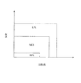
図2は、内燃機関1の運転状態毎に定められた、低圧EGR通路23を用いて行われるEGRと高圧EGR通路15を用いて行われるEGRの切替パターンを示した図である。図2の横軸は内燃機関1の機関回転数を表し、縦軸は内燃機関1の機関負荷を表している。
FIG. 2 is a diagram illustrating a switching pattern of EGR performed using the low
図2において、HPL領域は、内燃機関1の運転状態が低負荷低回転の領域であり、ここでは高圧EGR通路15を用いてEGRが行われる。図2のMIX領域は、内燃機関1の運転状態が中負荷中回転の領域であり、ここでは高圧EGR通路15と低圧EGR通路23が併用されてEGRが行われる。図2のLPL領域は、内燃機関1の運転状態が高負荷高回転の領域であり、ここでは低圧EGR通路23を用いてEGRが行われる。LPL領域より高回転又は高負荷の領域においてはEGRは行われない。
In FIG. 2, the HPL region is a region where the operating state of the
このように、高圧EGR通路15と低圧EGR通路23とを切り替えて、或いは併用してEGRを行うことによって、広範な運転領域においてEGRを行うことが可能になる。
As described above, EGR can be performed in a wide operation range by switching the high
また、上記の低圧EGR通路23と高圧EGR通路15の切り替えパターンにおいて、
内燃機関の運転状態に応じた低圧EGRガス量の基本量(以下「基本低圧EGRガス量」という)と高圧EGRガス量の基本量(以下「基本高圧EGRガス量」という)が定められている。本実施例では、さらに、排気浄化システムの状態に応じて基本低圧EGRガス量及び/又は基本高圧EGRガス量が補正される。以下、排気浄化装置32の状態に応じた低圧EGRガス量と高圧EGRガス量の補正制御について説明する。
In the switching pattern of the low
A basic amount of low-pressure EGR gas amount (hereinafter referred to as “basic low-pressure EGR gas amount”) and a basic amount of high-pressure EGR gas amount (hereinafter referred to as “basic high-pressure EGR gas amount”) according to the operating state of the internal combustion engine are determined. . In the present embodiment, the basic low pressure EGR gas amount and / or the basic high pressure EGR gas amount are further corrected in accordance with the state of the exhaust purification system. Hereinafter, correction control of the low pressure EGR gas amount and the high pressure EGR gas amount according to the state of the
まず、排気浄化装置32について説明する。
First, the
フィルタ20には、フィルタ20の使用に伴って排気中から捕集されたPMが堆積していく。フィルタ20に多量のPMが堆積すると、フィルタ20における圧力損失が増大し、内燃機関1の出力低下や燃料消費率の悪化を招く場合がある。そこで、フィルタ20におけるPMの堆積量が所定の堆積量以上になった場合には、フィルタ20に堆積したPMを酸化除去するフィルタ再生処理が適宜行われる。
The PM collected from the exhaust gas as the
所定の堆積量とは、内燃機関1の出力低下や燃料消費率の悪化を招く虞のあるPMの堆積量であり、予め実験等により求められている。
The predetermined accumulation amount is an accumulation amount of PM that may cause a decrease in the output of the
フィルタ再生処理は、具体的には、フィルタ20の温度を上昇させる昇温処理である。昇温処理によってフィルタ20の温度が上昇すると、フィルタ20に堆積したPMが加熱され、PMの酸化反応が促進される。
Specifically, the filter regeneration process is a temperature raising process for increasing the temperature of the
フィルタ20に対する昇温処理としては、例えば、トルクを発生させるための主噴射とは別に副噴射を行う方法を例示できる。この場合、内燃機関から排出される排気の温度が上昇するとともに、排気に含まれる未燃燃料が還元剤として酸化触媒33において酸化還元反応し、この酸化還元反応に伴う反応熱によって酸化触媒33より下流のフィルタ20に流入する排気の温度が上昇する。
As a temperature raising process for the
このように、フィルタ20に堆積したPMをフィルタ再生処理によって適宜酸化除去することで、フィルタ20に多量のPMが堆積して圧力損失が増大することを抑制できる。
Thus, by appropriately oxidizing and removing the PM deposited on the
ところで、上記のようなフィルタ再生処理を実施した場合、高圧EGRガスや低圧EGRガスの温度が過度に高温になる場合がある。 By the way, when the filter regeneration process as described above is performed, the temperature of the high pressure EGR gas or the low pressure EGR gas may become excessively high.
例えば、フィルタ20に対する昇温処理として副噴射が行われた場合、通常時の主噴射のみが行われている場合と比較して内燃機関の燃焼室の温度が高くなる。そのため、燃焼室周辺のエンジンヘッド等の機関部材の温度が高くなる。これに伴い、エンジンヘッドに近接して設けられている高圧EGR通路15の温度が高くなり、高圧EGRガスが高温になる可能性がある。
For example, when the sub-injection is performed as the temperature raising process for the
また、フィルタ再生処理の実施中は、フィルタ20に堆積したPMの酸化反応に伴う反応熱によって、フィルタ20の温度は非常に高温になる。そのため、フィルタ20を通過する排気が加熱され、高温の排気がフィルタ20から流出することになる。その結果、低圧EGRガスの温度が高温になる。
Further, during the filter regeneration process, the temperature of the
高圧EGRガスが高温になると、燃焼室に吸入されるガスの温度が高くなるため、燃焼過程でのスモークやNOxの発生量が増大する虞がある。また、高温の高圧EGRガスが大量に高圧EGR弁21を通過すると高圧EGR弁21の動作に不具合が発生する虞もある。
When the high-pressure EGR gas becomes high in temperature, the temperature of the gas sucked into the combustion chamber increases, and there is a risk that the amount of smoke and NOx generated during the combustion process increases. Further, if a large amount of high-temperature high-pressure EGR gas passes through the high-
低圧EGRガスが高温になると、コンプレッサハウジング6に流入する吸気ガスの温度
が高温になり、ターボチャージャ10の動作に不具合が発生する虞がある。また、高温の低圧EGRガスが大量に低圧EGR弁5や低圧EGRクーラ14を通過すると、低圧EGR弁5や低圧EGRクーラ14の動作に不具合が発生する虞もある。
When the low-pressure EGR gas becomes high temperature, the temperature of the intake gas flowing into the compressor housing 6 becomes high temperature, and there is a possibility that a malfunction may occur in the operation of the
これに対し、フィルタ再生処理の実施中において低圧EGRガス量や高圧EGRガス量(以下、「EGRガス量」と総称する場合もある)を減少させることで、高温の排気が大量に再循環されることに起因する上記のような不具合の発生を抑制することが考えられる。 On the other hand, by reducing the amount of low-pressure EGR gas or high-pressure EGR gas (hereinafter sometimes referred to as “EGR gas amount”) during the filter regeneration process, a large amount of high-temperature exhaust gas is recirculated. It is conceivable to suppress the occurrence of the above-described problems caused by the above.
これによると、フィルタ再生処理の実施中にのみEGRガス量に対する減量補正が行われ、フィルタ再生処理が終了した時点でEGRガス量に対する減量補正は解除されることになる。すなわち、フィルタ再生処理が終了した時点で通常時のEGRガス量に戻される。ここで、通常時とは、フィルタ再生処理の実行前又は実行後十分時間が経過し、フィルタ再生処理が行われていない時を表す。 According to this, the decrease correction for the EGR gas amount is performed only during the filter regeneration process, and the decrease correction for the EGR gas amount is canceled when the filter regeneration process is completed. That is, when the filter regeneration process is completed, the normal EGR gas amount is restored. Here, the normal time represents a time when a sufficient time elapses before or after the execution of the filter regeneration process and the filter regeneration process is not performed.
しかし、排気浄化装置32や、燃焼室やその周辺のエンジンヘッド等の機関部材等は、フィルタ再生処理が終了した後も暫くの間は高温状態が持続する傾向がある。従って、フィルタ再生処理の実施に起因する低圧EGRガスや高圧EGRガスの高温状態も、フィルタ再生処理の終了後も暫くの間持続する可能性がある。
However, the
そのため、フィルタ再生処理が終了した時点でEGRガス量に対する減量補正を解除すると、高温の排気が低圧EGR通路23や高圧EGR通路15を経由して大量に再循環する虞がある。
Therefore, if the reduction correction for the EGR gas amount is canceled at the time when the filter regeneration process is completed, there is a possibility that the high-temperature exhaust gas is recirculated in large quantities via the low-
そこで、本実施例では、フィルタ再生処理の終了後も、EGRガスの温度が所定の基準温度を超えている可能性がある期間はEGRガス量に対する減量補正を実施するようにした。具体的には、EGRガス温度が所定の基準温度を超えているか否かを判定し、EGRガス温度が所定の基準温度を超えていると判定された場合には、EGRガス量を減少させる補正が行われる。 Therefore, in this embodiment, even after the filter regeneration process is completed, the EGR gas amount is corrected for reduction during a period when the temperature of the EGR gas may exceed the predetermined reference temperature. Specifically, it is determined whether or not the EGR gas temperature exceeds a predetermined reference temperature, and when it is determined that the EGR gas temperature exceeds a predetermined reference temperature, a correction that decreases the EGR gas amount. Is done.
ここで、基準温度とは、上述のような不具合を発生させる虞がないEGRガス温度の上限値であり、予め実験等により求められている。 Here, the reference temperature is an upper limit value of the EGR gas temperature at which there is no possibility of causing the above-described problems, and is obtained in advance through experiments or the like.
低圧EGRガスの温度を推定する方法、或いは低圧EGRガスの温度が所定の第1基準温度を超えているか否かを判定する方法としては、例えば、低圧EGRガスの場合、クランクポジションセンサ25によって検出される機関回転数、アクセル開度センサ24によって検出される機関負荷、燃料噴射弁3に対するECU22の制御指令値から推定される燃料噴射量、水温センサ17によって検出される冷却水温度、油温センサ16によって検出される潤滑油温度、吸気温度センサ26によって検出される吸気ガスの温度、過給圧センサ27によって検出される過給圧、エアフローメータ30によって検出される吸入空気量等の、内燃機関1に備えられているセンサ類によって取得可能な諸パラメータに基づいてモデル計算を実行することで低圧EGRガス温度を推定しても良い。
As a method for estimating the temperature of the low-pressure EGR gas or a method for determining whether or not the temperature of the low-pressure EGR gas exceeds a predetermined first reference temperature, for example, in the case of the low-pressure EGR gas, detection is performed by the
モデル計算とは、上記のようなセンサ等によって検出可能なパラメータ群に基づいて物理量を理論計算する体系であり、予め実験等により求められ、ECU22のROMに記憶されている。ここで、第1基準温度とは、吸気系やEGR系に不具合を生じさせる虞のない低圧EGRガス温度の上限値であり、予め実験等により求められる。
Model calculation is a system for theoretically calculating physical quantities based on a group of parameters that can be detected by a sensor or the like as described above, which is obtained in advance by experiments or the like and stored in the ROM of the
また、低圧EGRクーラ14を流れる冷却水の、低圧EGRクーラ14の入り口と出口における温度差から低圧EGRガス温度を推定しても良い。
Further, the low-pressure EGR gas temperature may be estimated from the temperature difference between the inlet and the outlet of the low-pressure EGR cooler 14 in the coolant flowing through the low-
また、フィルタ20の温度からフィルタ20から流出する排気の温度を推定し、この推定された排気の温度に基づいて低圧EGRガス温度を推定しても良い。フィルタ20の温度は、フィルタ20の温度を検出するセンサをフィルタ20に設けて直接測定しても良いし、モデル計算によって推定しても良い。
Further, the temperature of the exhaust gas flowing out from the
また、フィルタ再生処理が終了してからの経過時間に基づいて低圧EGRガスの温度がどの温度領域に属しているかを推定するようにしても良い。例えば、フィルタ再生処理が終了してから所定期間は低圧EGRガスの温度が高温領域に属していると判定し、昇温処理が終了してから所定期間経過後は低圧EGRガスの温度は通常領域に属していると判定するようにしても良い。 Further, it may be estimated to which temperature region the temperature of the low-pressure EGR gas belongs based on the elapsed time from the end of the filter regeneration process. For example, it is determined that the temperature of the low-pressure EGR gas belongs to a high temperature region for a predetermined period after the filter regeneration process is completed, and the temperature of the low-pressure EGR gas is a normal region after the predetermined period has elapsed after the temperature increase process is completed. You may make it determine with belonging to.
ここで、高温領域とは、上述のような不具合を発生させる虞のある低圧EGRガス温度の領域である。通常領域とは、昇温処理の実行前又は実行後十分な時間が経過し、昇温処理が実施されていない時のEGRガス温度の領域である。この場合、第1基準温度とは、高温領域と通常領域との境界温度領域である。また、所定期間は、フィルタ再生処理が終了してから、低圧EGRガス温度が通常時の温度まで低下するのに要する時間として定めることができる。 Here, the high temperature region is a region of the low pressure EGR gas temperature that may cause the above-described problems. The normal region is a region of EGR gas temperature when a sufficient time has elapsed before or after execution of the temperature raising process and the temperature raising process is not being performed. In this case, the first reference temperature is a boundary temperature region between the high temperature region and the normal region. Further, the predetermined period can be determined as the time required for the low pressure EGR gas temperature to decrease to the normal temperature after the filter regeneration process is completed.
一方、高圧EGRガスの温度を推定する方法、或いは高圧EGRガスの温度が所定の第2基準温度を超えているか否かを判定する方法としては、例えば、高圧EGRガス温度をモデル計算によって推定する方法を例示することができる。ここで、第2基準温度とは、吸気系やEGR系に不具合を生じさせる虞のない高圧EGRガス温度の上限値であり、予め実験等により求められる。 On the other hand, as a method for estimating the temperature of the high pressure EGR gas or a method for determining whether or not the temperature of the high pressure EGR gas exceeds a predetermined second reference temperature, for example, the high pressure EGR gas temperature is estimated by model calculation. A method can be illustrated. Here, the second reference temperature is an upper limit value of the high-pressure EGR gas temperature that does not cause a problem in the intake system or the EGR system, and is obtained in advance by experiments or the like.
また、インマニ温度センサ28によって検出される吸気マニホールド8における吸気ガス温度と、吸気温度センサ26によって検出される吸気ガス温度との差に基づいて高圧EGRガス温度を推定することもできる。
The high-pressure EGR gas temperature can also be estimated based on the difference between the intake gas temperature in the intake manifold 8 detected by the intake
また、高圧EGR通路15の途中に高圧EGR通路15を流れる排気の温度を検出する高圧EGR温度センサ33を設けて、直接高圧EGRガス温度を検出するようにしても良い。
Further, a high pressure
また、水温センサ17によって検出される冷却水温度や油温センサ16によって検出される潤滑油温度に基づいて高圧EGRガス温度を推定しても良い。これは、冷却水温度や潤滑油温度が高い場合には、燃焼室周辺の機関部材が高温状態にあると推定できるからである。
Further, the high pressure EGR gas temperature may be estimated based on the coolant temperature detected by the water temperature sensor 17 or the lubricating oil temperature detected by the
また、フィルタ再生処理が終了してからの経過時間に基づいて高圧EGRガスの温度がどの温度領域に属しているかを推定するようにしても良い。例えば、フィルタ再生処理が終了してから所定期間は高圧EGRガスの温度が高温領域に属していると判定し、昇温処理が終了してから所定期間経過後は高圧EGRガスの温度は通常領域に属していると判定するようにしても良い。 Further, it may be estimated which temperature range the temperature of the high-pressure EGR gas belongs to based on the elapsed time after the filter regeneration process is completed. For example, it is determined that the temperature of the high-pressure EGR gas belongs to the high temperature region for a predetermined period after the filter regeneration process is completed, and the temperature of the high-pressure EGR gas is the normal region after the predetermined period has elapsed after the temperature increase process is completed. You may make it determine with belonging to.
以下、本実施例のECU22によって行われる、フィルタ再生処理終了後のEGRガス量の減量補正制御について、図3〜図6のフローチャートに基づいて説明する。図3〜図6のフローチャートはEGRガス量の減量補正制御を行うためのルーチンを示すフローチャートである。このルーチンはECU22によって所定期間毎に繰り返し実行される。
Hereinafter, the EGR gas amount reduction correction control after completion of the filter regeneration process performed by the
まず、ステップS301において、ECU22は、内燃機関1の運転状態を検出する。
具体的には、アクセル開度センサ24による検出値から内燃機関1の機関負荷を検出するとともに、クランクポジションセンサ25による検出値から内燃機関1の機関回転数を検出する。
First, in step S301, the
Specifically, the engine load of the
ステップS302において、ECU22は、前記ステップS301において検出した内燃機関1の運転状態に基づいて基本低圧EGRガス量を決定し、該基本低圧EGRガス量に対応する低圧EGR弁5の開度(以下「基本低圧EGR弁開度」という)DLを決定する。また、前記ステップS301において検出した内燃機関1の運転状態に基づいて基本高圧EGRガス量を決定し、該基本高圧EGRガス量に対応する高圧EGR弁21の開度(以下「基本高圧EGR弁開度」という)DHを決定する。
In step S302, the
ステップS303において、ECU22は、フィルタ20に対するフィルタ再生処理が終了したか否かを判定する。
In step S303, the
前記ステップS303において否定判定された場合、すなわち、フィルタ再生処理が終了していないと判定された場合、ECU22は、ステップS304に進む。ステップS304では、ECU22は、再生後カウンタΔtを0にリセットする。再生後カウンタΔtは、フィルタ再生処理が終了してからの経過時間を表す。ステップS304を実行した後、ECU22は本ルーチンの実行を一旦終了する。
If a negative determination is made in step S303, that is, if it is determined that the filter regeneration process has not ended, the
一方、前記ステップS303において肯定判定された場合、すなわち、フィルタ再生処理が終了したと判定された場合、ECU22は、ステップS305に進む。ステップS305では、ECU22は、再生後カウンタΔtを単位量増加させる。
On the other hand, if an affirmative determination is made in step S303, that is, if it is determined that the filter regeneration process has ended, the
続いて、ステップS306において、ECU22は、フィルタ再生処理が終了してから所定時間tbaseが経過したか否かを判定する。ここで、所定時間tbaseは、フィルタ再生処理の終了後、排気浄化装置32から排出される排気の温度及び内燃機関1のヘッド周辺の機関部材の温度が通常時(フィルタ再生処理を実行する前の時点)の温度にまで低下したと判定可能な経過時間であり、予め求められている。
Subsequently, in step S306, the
ステップS306において肯定判定された場合(Δt>tbase)は、ECU22は、フィルタ再生処理が終了してから十分に時間が経過し、排気浄化装置32及び内燃機関1の機関部材の温度は通常時の温度に戻っていると判定し、図4のステップS309に進む。
If an affirmative determination is made in step S306 (Δt> tbase), the
ステップS309では、ECU22は、低圧EGR弁5に対する開度制御指令値t_DLを前記ステップS302で求められた基本低圧EGR弁開度DLに設定するとともに、高圧EGR弁21に対する開度制御指令値t_DHを前記ステップS302で求められた基本高圧EGR弁開度DHに設定する。
In step S309, the
次いで、ステップS310に進み、ECU22は、前記ステップS309で決定された低圧EGR弁開度制御指令値t_DLによって低圧EGR弁5を制御するとともに、高圧EGR弁開度制御指令値t_DHによって高圧EGR弁21を制御する。
Next, the process proceeds to step S310, where the
ステップS310を実行した後、ECU22は本ルーチンの実行を一旦終了する。
After executing step S310, the
一方、前記ステップS306において否定判定された場合(Δt≦tbase)は、ECU22は、フィルタ再生処理が終了してから未だ十分に時間が経過しておらず、排気浄化装置32や内燃機関1の機関部材は依然として高温状態にあると判定し、ステップS307に進む。
On the other hand, when a negative determination is made in step S306 (Δt ≦ tbase), the
ステップS307では、ECU22は、低圧EGRガスの温度TLPLが第1基準温度TLPLTHを超えているか否かを判定する。ステップS307で肯定判定された場合(TLPL>TLPLTH)は、ECU22は、図6のステップS320に進み、低圧EGRガスが高温になっている場合のEGRガス量補正制御を行う。一方、ステップS307で否定判定された場合(TLPL≦TLPLTH)は、ECU22はステップS308に進む。
In step S307, the ECU 22 determines whether or not the temperature T LPL of the low-pressure EGR gas exceeds the first reference temperature T LPLTH . If an affirmative determination is made in step S307 (T LPL > T LPLTH ), the
ステップS308では、ECU22は、高圧EGRガスの温度THPLが第2基準温度THPLTHを超えているか否かを判定する。ステップS308で肯定判定された場合(THPL>THPLTH)は、ECU22は、図5のステップS311に進み、高圧EGRガスが高温になっている場合のEGRガス量補正制御を行う。一方、ステップS308で否定判定された場合(THPL≦THPLTH)は、ECU22は前記ステップS309に進む。
In step S308, the ECU 22 determines whether or not the temperature T HPL of the high-pressure EGR gas exceeds the second reference temperature T HPLTH . If an affirmative determination is made in step S308 (T HPL > T HPLTH ), the
図5は、高圧EGRガスが高温になっていると判定された場合のEGRガス量補正制御ルーチンを表すフローチャートである。 FIG. 5 is a flowchart showing an EGR gas amount correction control routine when it is determined that the high-pressure EGR gas is at a high temperature.
まず、ステップS311において、ECU22は、前記ステップS301において検出された内燃機関1の運転状態に基づいて、内燃機関1の運転状態が図2のどの運転領域に属しているか判定する。
First, in step S311, the
ステップS311において、内燃機関1の運転状態が図2のHPL領域に属していると判定された場合は、ECU22は、ステップS312に進む。
If it is determined in step S311 that the operating state of the
ステップS312では、ECU22は、フィルタ再生処理が終了してからの経過時間に応じた高圧EGRガス量の減量補正量を定める高圧EGR減量補正係数KHを求める。具体的には、再生後カウンタΔtに応じて高圧EGR減量補正係数KHを定めるマップから、前記ステップS305で求められた再生後カウンタΔtに対応する高圧EGR減量補正係数KHを求める。このマップは予め実験などにより求められ、ECU22内のROMに記憶されている。
In step S312, the
高圧EGR減量補正係数KHは1より小さい数値であり、定数であっても良いが、フィルタ再生処理が終了した後の経過時間に関する増加関数によって求められる値としてもよい。 The high-pressure EGR reduction correction coefficient KH is a numerical value smaller than 1 and may be a constant, or may be a value obtained by an increasing function related to the elapsed time after the filter regeneration processing is completed.
続くステップS313で、ECU22は、低圧EGR弁5に対するの開度制御指令値t_DLを0に設定するとともに、高圧EGR弁21に対する開度制御指令値t_DHを基本高圧EGR弁開度DHと前記ステップS312で求めた高圧EGR減量補正係数KHとの積として定める。すなわち、t_DH=DH×KHとする。
In subsequent step S313, the
次いで、ECU22はステップS319に進み、前記ステップS313で決定された低圧EGR弁開度制御指令値t_DLによって低圧EGR弁5を制御するとともに、高圧EGR弁開度制御指令値t_DHによって高圧EGR弁21を制御する。
Next, the
ステップS319を実行した後、ECU22は本ルーチンの実行を一旦終了する。
After executing step S319, the
前記ステップS311において内燃機関1の運転状態が図2のMIX領域に属していると判定された場合は、ECU22は、ステップS314に進む。
If it is determined in step S311 that the operating state of the
ステップS314では、ECU22は、低圧EGRガスの温度が低圧EGR増量可能条件を満たしているか否かを判定する。ここで、低圧EGR増量可能条件とは、低圧EGRガス量を増量することによってNOx発生量を低減可能となるような低圧EGRガス温度の条件であり、予め実験等により求められる。
In step S314, the
ステップS314で肯定判定された場合は、ECU22は、ステップS315に進む。一方、ステップS314で否定判定された場合は、ECU22は、後述するステップS329に進む。
If an affirmative determination is made in step S314, the
ステップS315では、ECU22は、フィルタ再生処理が終了してからの経過時間に応じた高圧EGRガス量の減量補正量を定める高圧EGR減量補正係数KMHと、低圧EGRガス量の増量補正量を定める低圧EGR増量補正係数KMLを求める。
In step S315, the
具体的には、再生後カウンタΔtに応じて高圧EGR減量補正係数KMHを定めるマップから、前記ステップS305で求められた再生後カウンタΔtに対応する高圧EGR減量補正係数KMHを求める。また、再生後カウンタΔtに応じて低圧EGR増量補正係数KMLを定めるマップから、前記ステップS305で求められた再生後カウンタΔtに対応する低圧EGR増量補正係数KMLを求める。これらのマップは予め実験などにより求められ、ECU22内のROMに記憶されている。
Specifically, the high-pressure EGR reduction correction coefficient KMH corresponding to the post-regeneration counter Δt obtained in step S305 is obtained from a map that determines the high-pressure EGR reduction correction coefficient KMH according to the post-regeneration counter Δt. Further, the low-pressure EGR increase correction coefficient KML corresponding to the post-regeneration counter Δt obtained in step S305 is obtained from a map that determines the low-pressure EGR increase correction coefficient KML according to the post-regeneration counter Δt. These maps are obtained in advance by experiments or the like and are stored in the ROM in the
高圧EGR減量補正係数KMHは1より小さい数値であり、定数であっても良いが、フィルタ再生処理が終了した後の経過時間に関する増加関数によって求められる値としてもよい。また、低圧EGR増量補正係数KMLは1より大きい数値であり、定数であっても良いが、フィルタ再生処理が終了した後の経過時間に関する減少関数によって求められる値としてもよい。 The high pressure EGR reduction correction coefficient KMH is a numerical value smaller than 1 and may be a constant, or may be a value obtained by an increasing function related to an elapsed time after the filter regeneration processing is completed. Further, the low-pressure EGR increase correction coefficient KML is a numerical value larger than 1, and may be a constant, or may be a value obtained by a decreasing function related to the elapsed time after the filter regeneration processing is completed.
続くステップS316で、ECU22は、低圧EGR弁5に対するの開度制御指令値t_DLを、基本低圧EGR弁開度DLと前記ステップS315で求めた低圧EGR増量補正係数KMLとの積として定める。すなわち、t_DL=DL×KMLとする。
In subsequent step S316, the
また、ECU22は、高圧EGR弁21に対する開度制御指令値t_DHを、基本高圧EGR弁開度DHと前記ステップS315で求めた高圧EGR減量補正係数KMHとの積として定める。すなわち、t_DH=DH×KMHとする。
Further, the
次いで、ECU22はステップS319に進み、前記ステップS316で決定された低圧EGR弁開度制御指令値t_DLによって低圧EGR弁5を制御するとともに、高圧EGR弁開度制御指令値t_DHによって高圧EGR弁21を制御する。
Next, the
ステップS319を実行した後、ECU22は本ルーチンの実行を一旦終了する。
After executing step S319, the
一方、ステップS314で否定判定された場合は、ECU22は、ステップS329に進む。
On the other hand, if a negative determination is made in step S314, the
ステップS329では、ECU22は、フィルタ再生処理が終了してからの経過時間に応じた高圧EGRガス量の減量補正量を定める高圧EGR減量補正係数KMHを求める。
In step S329, the
具体的には、再生後カウンタΔtに応じて高圧EGR減量補正係数KMHを定めるマップから、前記ステップS305で求められた再生後カウンタΔtに対応する高圧EGR減量補正係数KMHを求める。このマップは予め実験などにより求められ、ECU22内のROMに記憶されている。
Specifically, the high-pressure EGR reduction correction coefficient KMH corresponding to the post-regeneration counter Δt obtained in step S305 is obtained from a map that determines the high-pressure EGR reduction correction coefficient KMH according to the post-regeneration counter Δt. This map is obtained in advance by experiments or the like and is stored in the ROM in the
高圧EGR減量補正係数KMHは1より小さい数値であり、定数であっても良いが、フィルタ再生処理が終了した後の経過時間に関する増加関数によって求められる値としてもよい。 The high pressure EGR reduction correction coefficient KMH is a numerical value smaller than 1 and may be a constant, or may be a value obtained by an increasing function related to an elapsed time after the filter regeneration processing is completed.
続くステップS330で、ECU22は、低圧EGR弁5に対するの開度制御指令値t_DLを基本低圧EGR弁開度DLに設定するとともに、高圧EGR弁21に対する開度制御指令値t_DHを、基本高圧EGR弁開度DHと前記ステップS329で求めた高圧EGR減量補正係数KMHとの積として定める。すなわち、t_DH=DH×KMHとする。
In subsequent step S330, the
次いで、ECU22はステップS319に進み、前記ステップS330で決定された低圧EGR弁開度制御指令値t_DLによって低圧EGR弁5を制御するとともに、高圧EGR弁開度制御指令値t_DHによって高圧EGR弁21を制御する。
Next, the
ステップS319を実行した後、ECU22は本ルーチンの実行を一旦終了する。
After executing step S319, the
前記ステップS311において内燃機関1の運転状態が図2のLPL領域に属していると判定された場合は、ECU22はステップS317に進む。
If it is determined in step S311 that the operating state of the
ステップS317では、ECU22は、低圧EGR弁5に対する開度制御指令値t_DLを基本低圧EGR弁開度DLに設定するとともに、高圧EGR弁21に対する開度制御指令値t_DHを0に設定する。
In step S317, the
次いで、ECU22はステップS319に進み、前記ステップS317で決定された低圧EGR弁開度制御指令値t_DLによって低圧EGR弁5を制御するとともに、高圧EGR弁開度制御指令値t_DHによって高圧EGR弁21を制御する。
Next, the
ステップS319を実行した後、ECU22は本ルーチンの実行を一旦終了する。
After executing step S319, the
前記ステップS311において内燃機関1の運転状態が図2のEGRを行わない領域に属していると判定された場合は、ECU22はステップS318に進む。
If it is determined in step S311 that the operating state of the
ステップS318では、ECU22は、低圧EGR弁5に対する開度制御指令値t_DLを0に設定するとともに、高圧EGR弁21に対する開度制御指令値t_DHを0に設定する。
In step S318, the
次いで、ECU22はステップS319に進み、前記ステップS318で決定された低圧EGR弁開度制御指令値t_DLによって低圧EGR弁5を制御するとともに、高圧EGR弁開度制御指令値t_DHによって高圧EGR弁21を制御する。
Next, the
ステップS319を実行した後、ECU22は本ルーチンの実行を一旦終了する。
After executing step S319, the
図6は、低圧EGRガスが高温になっていると判定された場合のEGRガス量補正制御ルーチンを表すフローチャートである。 FIG. 6 is a flowchart showing an EGR gas amount correction control routine when it is determined that the low-pressure EGR gas is at a high temperature.
まず、ステップS320において、ECU22は、前記ステップS301において検出された内燃機関1の運転状態に基づいて、内燃機関1の運転状態が図2のどの運転領域に属しているか判定する。
First, in step S320, the
ステップS320において、内燃機関1の運転状態が図2のHPL領域に属していると判定された場合は、ECU22は、ステップS321に進む。
If it is determined in step S320 that the operating state of the
ステップS321では、ECU22は、低圧EGR弁5に対する開度制御指令値t_DLを0に設定するとともに、高圧EGR弁21に対する開度制御指令値t_DHを基本高圧EGR弁開度DHに設定する。
In step S321, the
次いで、ECU22はステップS328に進み、前記ステップS321で決定された低圧EGR弁開度制御指令値t_DLによって低圧EGR弁5を制御するとともに、高圧EGR弁開度制御指令値t_DHによって高圧EGR弁21を制御する。
Next, the
ステップS328を実行した後、ECU22は本ルーチンの実行を一旦終了する。
After executing step S328, the
前記ステップS320において内燃機関1の運転状態が図2のMIX領域に属していると判定された場合は、ECU22は、ステップS322に進む。
If it is determined in step S320 that the operating state of the
ステップS322では、ECU22は、高圧EGRガスの温度が高圧EGR増量可能条件を満たしているか否かを判定する。ここで、高圧EGR増量可能条件とは、高圧EGRガス量を増量することによってNOx発生量を低減可能となるような高圧EGRガス温度の条件である。
In step S322, the
ステップS322で肯定判定された場合は、ECU22は、ステップS323に進む。一方、ステップS322で否定判定された場合は、ECU22は、後述するステップS331に進む。
If an affirmative determination is made in step S322, the
ステップS323では、ECU22は、フィルタ再生処理が終了してからの経過時間に応じた低圧EGRガス量の減量補正量を定める低圧EGR減量補正係数KMLと、高圧EGRガス量の増量補正量を定める高圧EGR増量補正係数KMHを求める。
In step S323, the
具体的には、再生後カウンタΔtに応じて低圧EGR減量補正係数KMLを定めるマップから、前記ステップS305で求められた再生後カウンタΔtに対応する低圧EGR減量補正係数KMLを求める。また、再生後カウンタΔtに応じて高圧EGR増量補正係数KMHを定めるマップから、前記ステップS305で求められた再生後カウンタΔtに対応する高圧EGR増量補正係数KMHを求める。これらのマップは予め実験などにより求められ、ECU22内のROMに記憶されている。
Specifically, the low-pressure EGR reduction correction coefficient KML corresponding to the post-regeneration counter Δt obtained in step S305 is obtained from a map that determines the low-pressure EGR reduction correction coefficient KML according to the post-regeneration counter Δt. Further, the high-pressure EGR increase correction coefficient KMH corresponding to the post-reproduction counter Δt obtained in step S305 is obtained from the map that determines the high-pressure EGR increase correction coefficient KMH according to the post-reproduction counter Δt. These maps are obtained in advance by experiments or the like and are stored in the ROM in the
低圧EGR減量補正係数KMLは1より小さい数値であり、定数であっても良いが、フィルタ再生処理が終了した後の経過時間に関する増加関数によって求められる値としてもよい。また、高圧EGR増量補正係数KMHは1より大きい数値であり、定数であっても良いが、フィルタ再生処理が終了した後の経過時間に関する減少関数によって求められる値としてもよい。 The low-pressure EGR reduction correction coefficient KML is a numerical value smaller than 1, and may be a constant, or may be a value obtained by an increasing function related to the elapsed time after the filter regeneration processing is completed. Further, the high pressure EGR increase correction coefficient KMH is a numerical value larger than 1, and may be a constant, or may be a value obtained by a decreasing function related to the elapsed time after the filter regeneration processing is completed.
続くステップS324で、ECU22は、低圧EGR弁5に対するの開度制御指令値t_DLを、基本低圧EGR弁開度DLと前記ステップS323で求めた低圧EGR減量補正係数KMLとの積として定める。すなわち、t_DL=DL×KMLとする。また、高圧EGR弁21に対する開度制御指令値t_DHを、基本高圧EGR弁開度DHと前記ステップS323で求めた高圧EGR増量補正係数KMHとの積として定める。すなわち、t_DH=DH×KMHとする。
In subsequent step S324, the
次いで、ECU22はステップS328に進み、前記ステップS324で決定された低
圧EGR弁開度制御指令値t_DLによって低圧EGR弁5を制御するとともに、高圧EGR弁開度制御指令値t_DHによって高圧EGR弁21を制御する。
Next, the
ステップS328を実行した後、ECU22は本ルーチンの実行を一旦終了する。
After executing step S328, the
一方、ステップS322で否定判定された場合は、ECU22は、ステップS331に進む。
On the other hand, if a negative determination is made in step S322, the
ステップS331では、ECU22は、フィルタ再生処理が終了してからの経過時間に応じた低圧EGRガス量の減量補正量を定める低圧EGR減量補正係数KMLを求める。
In step S331, the
具体的には、再生後カウンタΔtに応じて低圧EGR減量補正係数KMLを定めるマップから、前記ステップS305で求められた再生後カウンタΔtに対応する低圧EGR減量補正係数KMLを求める。このマップは予め実験等により求められ、ECU22内のROMに記憶されている。
Specifically, the low-pressure EGR reduction correction coefficient KML corresponding to the post-regeneration counter Δt obtained in step S305 is obtained from a map that determines the low-pressure EGR reduction correction coefficient KML according to the post-regeneration counter Δt. This map is obtained in advance by experiments or the like and stored in the ROM in the
低圧EGR減量補正係数KMLは1より小さい数値であり、定数であっても良いが、フィルタ再生処理が終了した後の経過時間に関する増加関数によって求められる値としてもよい。 The low-pressure EGR reduction correction coefficient KML is a numerical value smaller than 1, and may be a constant, or may be a value obtained by an increasing function related to the elapsed time after the filter regeneration processing is completed.
続くステップS332で、ECU22は、低圧EGR弁5に対する開度制御指令値t_DLを基本低圧EGR弁開度DLと前記ステップS331で求めた低圧EGR減量補正係数KMLとの積として定める。すなわち、t_DL=DL×KMLとする。また、高圧EGR弁21に対する開度制御指令値t_DHを基本高圧EGR弁開度DHに設定する。
In subsequent step S332, the
次いで、ECU22はステップS328に進み、前記ステップS332で決定された低圧EGR弁開度制御指令値t_DLによって低圧EGR弁5を制御するとともに、高圧EGR弁開度制御指令値t_DHによって高圧EGR弁21を制御する。
Next, the
ステップS328を実行した後、ECU22は本ルーチンの実行を一旦終了する。
After executing step S328, the
前記ステップS320において内燃機関1の運転状態が図2のLPL領域に属していると判定された場合は、ECU22はステップS325に進む。
If it is determined in step S320 that the operating state of the
ステップS325では、ECU22は、フィルタ再生処理が終了してからの経過時間に応じた低圧EGRガス量の減量補正量を定める低圧EGR減量補正係数KLを求める。
In step S325, the
具体的には、再生後カウンタΔtに応じて低圧EGR減量補正係数KLを定めるマップから、前記ステップS305で求められた再生後カウンタΔtに対応する低圧EGR減量補正係数KLを求める。このマップは予め実験などにより求められ、ECU22内のROMに記憶されている。
Specifically, the low-pressure EGR reduction correction coefficient KL corresponding to the post-regeneration counter Δt obtained in step S305 is obtained from a map that determines the low-pressure EGR reduction correction coefficient KL according to the post-regeneration counter Δt. This map is obtained in advance by experiments or the like and is stored in the ROM in the
低圧EGR減量補正係数KLは1より小さい数値であり、定数であっても良いが、フィルタ再生処理が終了した後の経過時間に関する増加関数によって求められる値としてもよい。 The low-pressure EGR reduction correction coefficient KL is a numerical value smaller than 1 and may be a constant, or may be a value obtained by an increasing function related to the elapsed time after the filter regeneration processing is completed.
続くステップS326で、ECU22は、低圧EGR弁5に対するの開度制御指令値t_DLを基本低圧EGR弁開度DLと前記ステップS325で求めた低圧EGR減量補正係数KLとの積として定める。すなわち、t_DL=DL×KLとする。また、高圧EGR弁21に対する開度制御指令値t_DHを0に設定する。
In subsequent step S326, the
次いで、ECU22はステップS328に進み、前記ステップS326で決定された低圧EGR弁開度制御指令値t_DLによって低圧EGR弁5を制御するとともに、高圧EGR弁開度制御指令値t_DHによって高圧EGR弁21を制御する。
Next, the
ステップS328を実行した後、ECU22は本ルーチンの実行を一旦終了する。
After executing step S328, the
前記ステップS320において内燃機関1の運転状態が図2のEGRを行わない領域に属していると判定された場合は、ECU22はステップS327に進む。
If it is determined in step S320 that the operating state of the
ステップS327では、ECU22は、低圧EGR弁5に対する開度制御指令値t_DLを0に設定するとともに、高圧EGR弁21に対する開度制御指令値t_DHを0に設定する。
In step S327, the
次いで、ECU22はステップS328に進み、前記ステップS327で決定された低圧EGR弁開度制御指令値t_DLによって低圧EGR弁5を制御するとともに、高圧EGR弁開度制御指令値t_DHによって高圧EGR弁21を制御する。
Next, the
ステップS328を実行した後、ECU22は本ルーチンの実行を一旦終了する。
After executing step S328, the
図7は、上記のEGRガス量減量補正制御において、フィルタ再生処理終了後に低圧EGRガスが第1基準温度よりも高温であると判定され、内燃機関1の運転状態がMIX領域又はLPL領域に属している時に、低圧EGRガス量に対する減量補正制御が行われた場合の、低圧EGRガス温度と低圧EGR弁開度の時間変化を示すタイムチャートである。
FIG. 7 shows that in the above EGR gas amount reduction correction control, it is determined that the low pressure EGR gas is higher than the first reference temperature after completion of the filter regeneration process, and the operating state of the
図7(A)は排気浄化装置32から排出される排気の温度の時間変化を示している。図7(A)の横軸は時間を表し、縦軸は排気温度を表す。図7(B)は低圧EGR弁5の開度の時間変化を示している。図7(B)の横軸は時間を表し、縦軸は低圧EGR弁5の開度を表す。図7(B)の破線で描かれた線は従来の低圧EGR弁開度制御を行った場合の低圧EGR弁開度の時間変化を表し、図7(B)の実線で描かれた線は本実施例の低圧EGR弁開度制御を行った場合の低圧EGR弁開度の時間変化を表している。
FIG. 7A shows the change over time in the temperature of the exhaust discharged from the
図7において、時刻t0でフィルタ再生処理が開始され、排気浄化装置32から排出される排気の温度が上昇し始める。そして、このフィルタ再生処理の開始と同期して低圧EGR弁開度が小さくされる。
In FIG. 7, the filter regeneration process is started at time t0, and the temperature of the exhaust discharged from the
時刻t0〜t1の期間に行われる昇温処理によってフィルタ20が昇温され、これに伴って排気浄化装置32から流出する排気の温度が上昇する。
The temperature of the
時刻t2においてフィルタ再生処理が終了する。従来の低圧EGR弁開度制御では、図7(B)の破線に示されるように、この時点で低圧EGR弁開度が基本低圧EGR弁開度に戻される。しかし、図7(A)に示されるように、時刻t2から暫くの期間は排気浄化装置32から排出される排気は依然として高温であり、時刻t2からの時間経過に伴って徐々に温度が低下していく。
The filter regeneration process ends at time t2. In the conventional low pressure EGR valve opening control, as shown by the broken line in FIG. 7B, at this time, the low pressure EGR valve opening is returned to the basic low pressure EGR valve opening. However, as shown in FIG. 7A, the exhaust gas discharged from the
そのため、従来の低圧EGR弁開度制御を行った場合、フィルタ再生処理終了直後の依然として高温の排気が低圧EGR通路23を経由して大量に再循環され、これに起因して吸気系やEGR系に種々の不具合が発生する虞があった。
Therefore, when the conventional low-pressure EGR valve opening degree control is performed, the still hot exhaust gas immediately after the end of the filter regeneration process is recirculated in large quantities via the low-
それに対し、本実施例では、図7(B)の実線で示されるように、フィルタ再生処理の終了後暫くの間は低圧EGR弁開度が小さくされたまま維持され、その後、排気温度の推移に合わせて低圧EGR弁開度が段階的に大きくされて基本低圧EGR弁開度に戻されるようにしている。 On the other hand, in this embodiment, as indicated by the solid line in FIG. 7B, the low-pressure EGR valve opening is kept small for a while after the filter regeneration process is finished, and then the transition of the exhaust gas temperature Accordingly, the low-pressure EGR valve opening is increased stepwise and returned to the basic low-pressure EGR valve opening.
すなわち、フィルタ再生処理が終了した直後の、排気が依然として高温の場合には低圧EGRガス量が少なくされ、低圧EGRガス温度の低下に合わせて徐々に低圧EGRガス量が基本低圧EGRガス量に戻される。これにより、フィルタ再生処理終了直後の高温の排気が低圧EGR通路23を介して大量に再循環されることを抑制できる。
That is, when the exhaust gas is still hot immediately after the filter regeneration process is finished, the low-pressure EGR gas amount is reduced, and the low-pressure EGR gas amount gradually returns to the basic low-pressure EGR gas amount as the low-pressure EGR gas temperature decreases. It is. Thereby, it is possible to suppress a large amount of high-temperature exhaust gas immediately after the completion of the filter regeneration process from being recirculated through the low-
なお、本実施例では、フィルタ再生処理が終了した後の低圧EGR弁開度は、フィルタ再生処理が終了してからの経過時間が長くなるに従って徐々に大きくされ、段階的に基本低圧EGR弁開度に戻されている。これにより、低圧EGRガス温度はフィルタ再生処理が終了した後、徐々に通常時の温度に低下していくので、これに合わせて低圧EGRガス量に対する減量補正量を少なくすることができる。 In this embodiment, the low pressure EGR valve opening after the filter regeneration process is finished is gradually increased as the elapsed time from the end of the filter regeneration process becomes longer, and the basic low pressure EGR valve is opened step by step. It has been returned to the degree. As a result, the low pressure EGR gas temperature gradually decreases to the normal temperature after the filter regeneration process is completed, and accordingly, the reduction correction amount for the low pressure EGR gas amount can be reduced.
低圧EGRガス量に対する減量補正はEGR率の低下につながるため、このように低圧EGRガス量に対する減量補正量を可及的に早期に少なくしていくことによって、NOxの生成量を低減することができる。その結果、NOx排出量の抑制と、高温の排気が低圧EGR通路23を介して大量に再循環されることによる不具合の抑制とを両立することが可能になる。
Since the reduction correction for the low-pressure EGR gas amount leads to a decrease in the EGR rate, the amount of NOx generated can be reduced by reducing the reduction correction amount for the low-pressure EGR gas amount as early as possible. it can. As a result, it is possible to achieve both suppression of the NOx emission amount and suppression of problems caused by a large amount of high-temperature exhaust gas being recirculated through the low-
上記の実施例には、本発明の本旨を逸脱しない範囲で種々の変更を加えることが可能である。例えば、上記の実施例では、排気浄化装置としてフィルタを備え、フィルタに対するフィルタ再生処理の実施に起因してEGRガスが高温になった場合のEGRガス量の減量補正制御について説明したが、排気浄化装置としてNOx触媒を備え、NOx触媒の硫黄被毒回復制御に起因してEGRガス温度が高温になった場合についても同様に本発明を適用することができる。 Various modifications can be made to the above-described embodiment without departing from the spirit of the present invention. For example, in the above-described embodiment, the EGR gas amount reduction correction control when the EGR gas is heated due to the filter regeneration process performed on the filter and the EGR gas has been described has been described. The present invention can be similarly applied to a case where a NOx catalyst is provided as an apparatus and the EGR gas temperature becomes high due to the sulfur poisoning recovery control of the NOx catalyst.
また、上記実施例ではフィルタ再生処理の終了後低圧EGR弁開度を段階的に基本低圧EGR弁開度に戻す減量補正制御を説明したが、フィルタ再生処理の終了後における低圧EGR弁開度が基本低圧EGR弁開度より小さくされる開度制御であればどのような制御であっても良い。例えば、フィルタ再生処理の実行中の開度を図7の時刻t2+tbaseまで維持して、時刻t2+tbaseにおいて基本低圧EGR弁開度に戻しても良い。 In the above embodiment, the reduction correction control for returning the low pressure EGR valve opening to the basic low pressure EGR valve opening stepwise after completion of the filter regeneration processing has been described. However, the low pressure EGR valve opening after completion of the filter regeneration processing is described. Any control may be used as long as the opening control is smaller than the basic low pressure EGR valve opening. For example, the opening during the filter regeneration process may be maintained until time t2 + tbase in FIG. 7 and returned to the basic low pressure EGR valve opening at time t2 + tbase.
また、上記のタイムチャートでは低圧EGR弁開度の制御についてのみ図示したが、高圧EGR弁開度についても同様の開度制御を行うことができる。また、高圧EGR弁開度制御と低圧EGR弁開度制御とは同一態様である必要はない。 In the above time chart, only the control of the low pressure EGR valve opening is shown, but the same opening degree control can be performed for the high pressure EGR valve opening. Further, the high pressure EGR valve opening degree control and the low pressure EGR valve opening degree control need not be the same mode.
1 内燃機関
2 気筒
3 燃料噴射弁
4 エアクリーナ
5 低圧EGR弁
6 コンプレッサハウジング
7 タービンハウジング
8 吸気マニホールド
9 吸気通路
10 ターボチャージャ
11 排気絞り弁
12 スロットル弁
13 インタークーラ
14 低圧EGRクーラ
15 高圧EGR通路
16 油温センサ
17 水温センサ
18 排気マニホールド
19 排気通路
20 フィルタ
21 高圧EGR弁
22 ECU
23 低圧EGR通路
24 アクセル開度センサ
25 クランクポジションセンサ
26 吸気温度センサ
27 過給圧センサ
28 インマニ温度センサ
29 差圧センサ
30 エアフローメータ
31 アクセルペダル
32 排気浄化装置
33 酸化触媒
DESCRIPTION OF
23 Low
Claims (4)
前記タービンより下流の排気通路に設けられた排気浄化装置と、
前記排気浄化装置より下流の排気通路と前記コンプレッサより上流の吸気通路とを接続する低圧EGR通路と、
前記タービンより上流の排気通路と前記コンプレッサより下流の吸気通路とを接続する高圧EGR通路と、
前記内燃機関の運転状態に応じて前記低圧EGR通路及び前記高圧EGR通路を切り替えて、或いは併用して前記内燃機関に排気を再循環させるEGR手段と、
前記内燃機関の運転状態に応じて前記低圧EGR通路を介して前記内燃機関に再循環される低圧EGRガスの基本量及び前記高圧EGR通路を介して前記内燃機関に再循環される高圧EGRガスの基本量を決定するEGRガス量決定手段と、
前記排気浄化装置の温度を昇温させる昇温処理を行う昇温手段と、
高圧EGRガスの温度が所定の第2基準温度を超えているか否かを判定する判定手段と
、
前記昇温処理の実行終了後において、前記内燃機関の運転状態が、前記高圧EGR通路のみを用いて排気の再循環が行われる運転状態又は前記低圧EGR通路及び前記高圧EGR通路を併用して排気の再循環が行われる運転状態である時に、高圧EGRガスの温度が前記第2基準温度を超えていると前記判定手段によって判定される期間中は、高圧EGRガスの量を前記EGRガス量決定手段によって決定される前記高圧EGRガスの基本量より減少させる補正手段と、
を備えること特徴とする内燃機関の排気浄化システム。 A turbocharger having a compressor in the intake passage of the internal combustion engine and a turbine in the exhaust passage of the internal combustion engine;
An exhaust purification device provided in an exhaust passage downstream of the turbine;
A low pressure EGR passage connecting an exhaust passage downstream from the exhaust purification device and an intake passage upstream from the compressor;
A high pressure EGR passage connecting an exhaust passage upstream of the turbine and an intake passage downstream of the compressor;
EGR means for switching the low-pressure EGR passage and the high-pressure EGR passage according to the operating state of the internal combustion engine or using them together to recirculate exhaust gas to the internal combustion engine;
The basic amount of low-pressure EGR gas recirculated to the internal combustion engine via the low-pressure EGR passage according to the operating state of the internal combustion engine and the high-pressure EGR gas recirculated to the internal combustion engine via the high-pressure EGR passage EGR gas amount determining means for determining a basic amount;
A temperature raising means for performing a temperature raising process for raising the temperature of the exhaust purification device;
Determining means for determining whether the temperature of the high-pressure EGR gas exceeds a predetermined second reference temperature;
After the execution of the temperature raising process, the operating state of the internal combustion engine is an operating state in which exhaust gas is recirculated using only the high-pressure EGR passage, or exhaust gas that is combined with the low-pressure EGR passage and the high-pressure EGR passage. During the operation state in which the recirculation is performed, the amount of the high-pressure EGR gas is determined during the period in which the determination means determines that the temperature of the high-pressure EGR gas exceeds the second reference temperature. Correction means for reducing the basic amount of the high-pressure EGR gas determined by the means;
An exhaust purification system for an internal combustion engine, comprising:
前記補正手段は、前記昇温処理の実行終了後において、前記内燃機関の運転状態が、前記低圧EGR通路及び前記高圧EGR通路を併用して排気の再循環が行われる運転状態である時に、高圧EGRガスの温度が前記第2基準温度を超えていると前記判定手段によって判定される期間中は、高圧EGRガスの量を前記EGRガス量決定手段によって決定される前記高圧EGRガスの基本量より減少させるとともに、低圧EGRガスの温度が所定の低圧EGR増量可能条件を満たす場合には低圧EGRガスの量を前記EGRガス量決定手
段によって決定される前記低圧EGRガスの基本量より増加させる
ことを特徴とする内燃機関の排気浄化システム。 In claim 1 ,
The correction means is configured such that, after the completion of the temperature raising process, when the operating state of the internal combustion engine is an operating state in which exhaust gas is recirculated by using the low pressure EGR passage and the high pressure EGR passage together. During a period in which the determination means determines that the temperature of the EGR gas exceeds the second reference temperature, the amount of high-pressure EGR gas is determined from the basic amount of the high-pressure EGR gas determined by the EGR gas amount determination means. When the temperature of the low-pressure EGR gas satisfies a predetermined low-pressure EGR increase possible condition, the amount of the low-pressure EGR gas is increased from the basic amount of the low-pressure EGR gas determined by the EGR gas amount determining means. An exhaust gas purification system for an internal combustion engine.
前記補正手段は、前記昇温処理が終了した時点からの経過時間が長くなるほど高圧EGRガスの量の減少量を少なくすることを特徴とする内燃機関の排気浄化システム。 In claim 1 or 2 ,
The exhaust gas purification system for an internal combustion engine, characterized in that the correction means decreases the amount of decrease in the amount of high-pressure EGR gas as the elapsed time from the time when the temperature raising process ends.
前記補正手段は、前記昇温処理が終了した時点からの経過時間が長くなるほど低圧EGRガスの量の増加量を少なくすることを特徴とする内燃機関の排気浄化システム。 In claim 2 ,
The exhaust gas purification system for an internal combustion engine, characterized in that the correction means decreases the increase amount of the low-pressure EGR gas as the elapsed time from the time when the temperature raising process is completed becomes longer.
Priority Applications (3)
| Application Number | Priority Date | Filing Date | Title |
|---|---|---|---|
| JP2006215654A JP4240086B2 (en) | 2006-08-08 | 2006-08-08 | Exhaust gas purification system for internal combustion engine |
| DE602007001647T DE602007001647D1 (en) | 2006-08-08 | 2007-08-08 | Emission control system of an internal combustion engine and control method of the system |
| EP07114015A EP1892400B1 (en) | 2006-08-08 | 2007-08-08 | Exhaust purification system of internal combustion engine, and control method of the system |
Applications Claiming Priority (1)
| Application Number | Priority Date | Filing Date | Title |
|---|---|---|---|
| JP2006215654A JP4240086B2 (en) | 2006-08-08 | 2006-08-08 | Exhaust gas purification system for internal combustion engine |
Publications (2)
| Publication Number | Publication Date |
|---|---|
| JP2008038803A JP2008038803A (en) | 2008-02-21 |
| JP4240086B2 true JP4240086B2 (en) | 2009-03-18 |
Family
ID=38736069
Family Applications (1)
| Application Number | Title | Priority Date | Filing Date |
|---|---|---|---|
| JP2006215654A Expired - Fee Related JP4240086B2 (en) | 2006-08-08 | 2006-08-08 | Exhaust gas purification system for internal combustion engine |
Country Status (3)
| Country | Link |
|---|---|
| EP (1) | EP1892400B1 (en) |
| JP (1) | JP4240086B2 (en) |
| DE (1) | DE602007001647D1 (en) |
Families Citing this family (17)
| Publication number | Priority date | Publication date | Assignee | Title |
|---|---|---|---|---|
| US8630787B2 (en) | 2005-12-20 | 2014-01-14 | Borgwarner Inc. | Controlling exhaust gas recirculation in a turbocharged engine system |
| KR101585867B1 (en) | 2005-12-20 | 2016-01-21 | 보그워너 인코포레이티드 | Controlling exhaust gas recirculation in a turbocharged compression-ignition engine system |
| JP2008150955A (en) * | 2006-12-14 | 2008-07-03 | Denso Corp | Exhaust gas recirculating device |
| JP4301296B2 (en) * | 2007-01-18 | 2009-07-22 | トヨタ自動車株式会社 | Exhaust gas recirculation system for internal combustion engines |
| FR2928182A3 (en) * | 2008-02-28 | 2009-09-04 | Renault Sas | Air flow controlling method for supercharged diesel engine of car, involves selectively activating high and low pressure recycling loops based on value of operating parameter of engine, for recycling part of exhaust gas |
| FR2928416B1 (en) * | 2008-03-10 | 2011-02-11 | Renault Sas | EXHAUST ARCHITECTURE OF AN INTERNAL COMBUSTION ENGINE, INTERNAL COMBUSTION ENGINE COMPRISING SUCH AN EXHAUST ARCHITECTURE AND METHODS USING THE ENGINE AND EXHAUST ARCHITECTURE |
| FR2928410A1 (en) * | 2008-03-10 | 2009-09-11 | Renault Sas | Particle filter regenerating method for internal combustion engine of motor vehicle, involves introducing gas into combustion chamber if estimated charging and loading are respectively lower than charging and loading threshold values |
| FR2932531B1 (en) * | 2008-06-16 | 2011-04-15 | Renault Sas | METHOD FOR CONTROLLING RECIRCULATION OF EXHAUST GASES IN A RECIRCULATION CIRCUIT |
| FR2944317A3 (en) * | 2009-04-10 | 2010-10-15 | Renault Sas | Gas intake and exhaust system for internal combustion engine of motor vehicle, has control unit controlling valve relative to sensors measurements, where valve is arranged in outlet of exhaust of motor vehicle |
| EP2474731B1 (en) * | 2009-09-03 | 2020-08-19 | Toyota Jidosha Kabushiki Kaisha | Exhaust recirculation device for internal combustion engine |
| US8042527B2 (en) | 2010-08-05 | 2011-10-25 | Ford Global Technologies, Llc | Coordination of HP and LP EGR |
| JP5716519B2 (en) * | 2011-04-27 | 2015-05-13 | トヨタ自動車株式会社 | Exhaust gas recirculation system for internal combustion engines |
| US8914221B2 (en) * | 2012-01-25 | 2014-12-16 | General Electric Company | Methods and systems for exhaust gas recirculation |
| US10323589B2 (en) | 2013-12-20 | 2019-06-18 | Toyota Jidosha Kabushiki Kaisha | Exhaust gas control apparatus for internal combustion engine |
| JP6191702B2 (en) * | 2013-12-20 | 2017-09-06 | トヨタ自動車株式会社 | Exhaust gas purification device for internal combustion engine |
| KR101567171B1 (en) | 2013-12-27 | 2015-11-06 | 현대자동차주식회사 | System of recycling exhaust heat from internal combustion engine |
| RU2730216C2 (en) * | 2016-05-18 | 2020-08-19 | Форд Глобал Текнолоджиз, Ллк | Method of operating an assembled motor |
Family Cites Families (2)
| Publication number | Priority date | Publication date | Assignee | Title |
|---|---|---|---|---|
| JP4165415B2 (en) * | 2004-02-27 | 2008-10-15 | 日産自動車株式会社 | Engine control device |
| JP2006029239A (en) * | 2004-07-16 | 2006-02-02 | Toyota Motor Corp | Exhaust emission control filter overheat prevention device |
-
2006
- 2006-08-08 JP JP2006215654A patent/JP4240086B2/en not_active Expired - Fee Related
-
2007
- 2007-08-08 EP EP07114015A patent/EP1892400B1/en active Active
- 2007-08-08 DE DE602007001647T patent/DE602007001647D1/en active Active
Also Published As
| Publication number | Publication date |
|---|---|
| EP1892400A3 (en) | 2008-04-02 |
| EP1892400B1 (en) | 2009-07-22 |
| DE602007001647D1 (en) | 2009-09-03 |
| EP1892400A2 (en) | 2008-02-27 |
| JP2008038803A (en) | 2008-02-21 |
Similar Documents
| Publication | Publication Date | Title |
|---|---|---|
| JP4240086B2 (en) | Exhaust gas purification system for internal combustion engine | |
| JP4285528B2 (en) | Exhaust gas recirculation system for internal combustion engines | |
| JP4240101B2 (en) | EGR system for internal combustion engine | |
| JP4611941B2 (en) | Exhaust gas recirculation device for internal combustion engine | |
| JP4333725B2 (en) | Exhaust gas recirculation device for internal combustion engine | |
| JP4453602B2 (en) | Exhaust gas purification system for internal combustion engine | |
| JP4670592B2 (en) | Exhaust gas recirculation system for internal combustion engines | |
| JP2006316746A (en) | Exhaust emission control device for internal combustion engine | |
| JP4802992B2 (en) | Exhaust gas recirculation device for internal combustion engine | |
| JP4134678B2 (en) | Exhaust gas recirculation device for an internal combustion engine with a supercharger | |
| JP4893383B2 (en) | Exhaust gas recirculation device for internal combustion engine | |
| JP2007040269A (en) | Back pressure control device of engine | |
| JP5240514B2 (en) | Engine exhaust gas recirculation system | |
| JP4333230B2 (en) | Exhaust gas purification system for internal combustion engine | |
| JP2010038055A (en) | Control device for internal combustion engine | |
| JP4706592B2 (en) | EGR system for internal combustion engine | |
| JP2008128115A (en) | Exhaust emission control system for internal combustion engine | |
| JP4910849B2 (en) | EGR system for internal combustion engine | |
| JP5796277B2 (en) | Exhaust gas purification system | |
| JP2010007634A (en) | Exhaust emission control device for an internal combustion engine | |
| JP2009030453A (en) | Control device of internal combustion engine | |
| JP2008157135A (en) | Egr control device for engine | |
| JP2010185351A (en) | Exhaust gas recirculation device | |
| JP5796278B2 (en) | Exhaust gas purification system | |
| JP6769415B2 (en) | Exhaust treatment device |
Legal Events
| Date | Code | Title | Description |
|---|---|---|---|
| A977 | Report on retrieval |
Free format text: JAPANESE INTERMEDIATE CODE: A971007 Effective date: 20080818 |
|
| A131 | Notification of reasons for refusal |
Free format text: JAPANESE INTERMEDIATE CODE: A131 Effective date: 20080826 |
|
| A521 | Request for written amendment filed |
Free format text: JAPANESE INTERMEDIATE CODE: A523 Effective date: 20081027 |
|
| TRDD | Decision of grant or rejection written | ||
| A01 | Written decision to grant a patent or to grant a registration (utility model) |
Free format text: JAPANESE INTERMEDIATE CODE: A01 Effective date: 20081202 |
|
| A01 | Written decision to grant a patent or to grant a registration (utility model) |
Free format text: JAPANESE INTERMEDIATE CODE: A01 |
|
| A61 | First payment of annual fees (during grant procedure) |
Free format text: JAPANESE INTERMEDIATE CODE: A61 Effective date: 20081215 |
|
| FPAY | Renewal fee payment (event date is renewal date of database) |
Free format text: PAYMENT UNTIL: 20120109 Year of fee payment: 3 |
|
| R151 | Written notification of patent or utility model registration |
Ref document number: 4240086 Country of ref document: JP Free format text: JAPANESE INTERMEDIATE CODE: R151 |
|
| FPAY | Renewal fee payment (event date is renewal date of database) |
Free format text: PAYMENT UNTIL: 20120109 Year of fee payment: 3 |
|
| FPAY | Renewal fee payment (event date is renewal date of database) |
Free format text: PAYMENT UNTIL: 20130109 Year of fee payment: 4 |
|
| FPAY | Renewal fee payment (event date is renewal date of database) |
Free format text: PAYMENT UNTIL: 20130109 Year of fee payment: 4 |
|
| LAPS | Cancellation because of no payment of annual fees |