JP4237876B2 - elevator - Google Patents
elevator Download PDFInfo
- Publication number
- JP4237876B2 JP4237876B2 JP17534399A JP17534399A JP4237876B2 JP 4237876 B2 JP4237876 B2 JP 4237876B2 JP 17534399 A JP17534399 A JP 17534399A JP 17534399 A JP17534399 A JP 17534399A JP 4237876 B2 JP4237876 B2 JP 4237876B2
- Authority
- JP
- Japan
- Prior art keywords
- elevator
- button
- visually impaired
- floor
- person
- Prior art date
- Legal status (The legal status is an assumption and is not a legal conclusion. Google has not performed a legal analysis and makes no representation as to the accuracy of the status listed.)
- Expired - Fee Related
Links
Images


Landscapes
- Indicating And Signalling Devices For Elevators (AREA)
- Elevator Control (AREA)
Description
【0001】
【発明の属する技術分野】
本発明は、視覚障害者が利用するに好適なエレベータの運転制御装置にかんする。
【0002】
【従来の技術】
特開平7−206290号公報には、視覚障害者専用乗場ボタンを設け、このボタンを連動してエレベータ利用者にかご呼び登録状態を音声で知らせる放送設備を設けることが記載されている。
【0003】
特開平9−110319号公報には、乗場及び乗かごに呼び登録装置を含み、前記呼び登録装置に視覚障害者が操作できるように点字で表した点字板を装備した自動運転方式のエレベータにおいて、前記点字板に人体が接触したことを感知するセンサを取付、その感知信号により、触れた点字銘板の点字内容を音声案内装置により音声で放送案内することを特徴とするエレベータの視覚障害用音声案内装置が記載されている。
【0004】
また、特開平8−34581号公報には、エレベータの利用者が触れたことを検出する点字銘板、及び前記点字銘板が触れられたことを検出してから一定時間以内にボタンスイッチが押されたことを検出したときには戸の電動開閉装置へ戸開時間延長の信号を送る戸開時間延長手段を備えたことを特徴とするエレベータの制御装置が記載されている。
【0005】
【発明が解決しようとする課題】
従来技術には次のような問題点を包含する。
・視覚障害者には扉の開閉や現在階床などがわかりにくい。音声案内装置が設置されているものもあるが、十分な内容を提供しているとも限らず、逆に、エレベータ設置部にオフィスなどが近接していると、音声案内がかえってオフィスで労働する人にとって音声ノイズとなる場合がある。
・視覚に障害があるとエレベータの乗り降りや操作に時間がかかる場合があり、扉の開閉時間が短いと扉の開閉タイミングに合わせて乗り降りすることが困難である。
・エレベータホールに複数基のエレベータがある場合、音声案内装置があってもホールに反響してどのエレベータが来たかわかりづらい事がある。
・点字銘板に触れた人を視覚障害者とみなして自動認識するという発明もあるが、視覚障害者のうち点字を読める人の割合は低く、点字銘板にすら触れない視覚障害者も相当数いると考えられる。
【0006】
本発明は、かかる点に鑑み、視覚障害者がエレベータを利用する場合のエレベータ呼びあるいは行先階ボタン探索の行動に沿って利用者が視覚障害者であるかどうかを判別するようにして確実に視覚障害者認識を行うようにするもので、視覚障害者運転モードによって通常運転時の運転効率を落さずに済み、また周りの人たちへの音声ノイズを減らすことのできるエレベータ運転制御装置を提供することを目的とする。
【0007】
【課題を解決するための手段】
エレベータホールのエレベータを呼ぶ操作盤やエレベータ内の操作盤の操作ボタン及びフェースプレートに触覚センサーを設け、視覚障害者がボタンを探す行為を論理化したセンシングを行うことで視覚障害者を自動認識する。これにより、視覚障害者にエレベータの状況や視覚障害者に合ったエレベータの作動(使い勝手)を提供することができる。ここでは、エレベータ呼びボタン(上り)、エレベータ呼びボタン(下り)を総称して乗り場ボタンと呼び、および乗り場ボタンと行先階ボタンとを総称して操作ボタンという。
【0008】
・視覚障害者は目的の操作ボタンを操作するために、フェースプレート部やボタンの数、位置などを確認しながら探していく。この一連の動作と触れる部分に着目し、触れた部分と押したボタン、そのタイミングの関係から視覚障害者かどうかを判別する。
【0009】
・上記で視覚障害者と判別した場合、扉開放時間を延長したり、視覚障害者に最適な音声情報を付加し、視覚障害者のエレベータの使い勝手を向上させることができる。
【0010】
・自動認識により、視覚障害者の利用時のみ、視覚障害者モードとして上記の機能を作動させることで通常運転時の運転効率を落とさずに済み、また、周りの人たちへの音声ノイズなども最低限に減らすことができる。
【0011】
・また、上記の方式であれば、点字を読まない、つまり点字銘板に頼らない視覚障害者も、視覚障害者と判別でき、より多くの視覚障害者の使い勝手を向上させることができる。
【0012】
・視覚障害者専用のボタンなどを設ける訳ではないので、触覚情報として混乱させることなく、障害者に対する健常者の特別視にもつながらないというメリットがある。
【0013】
・従来の技術の応用、簡単なシステムで構築できるため、コストアップを押さえることができる。
【0014】
例えば、途中階の乗り場ボタンをタッチセンサーのついたストロークボタンとし、触れた情報と時間の関係をそれぞれ計算し、視覚障害者かどうかを判別するようにする。視覚障害者と判別した場合には、エレベータの制御を変更し、扉開閉時間を延長したり、視覚障害者に最適な音声情報を付加する。また、フェースプレートをタッチセンサーとし、触れた部分を特定することで視覚障害者と判別することもできる。
【0015】
本発明は、具体的には次ぎに示す装置を提供する。
【0016】
本発明は、乗り場ボタンを備えてエレベータホールに設けられるホール側操作盤と、前記乗り場ボタンの操作に基づいてエレベータの運転を制御するエレベータ運転制御装置を備えたエレベータにおいて、前記ホール側操作盤は、フェースプレート部と、該フェースプレート部に設けられて利用者の押下する操作を検知する乗り場ボタンと、該乗り場ボタンの周囲を囲むように設けられて利用者のタッチする操作を検知するタッチセンサとを備え、前記エレベータ運転制御装置は、通常運転モードと視覚障害者運転モードとを備えるとともに、前記タッチセンサがタッチされた後に、前記乗り場ボタンが押下されたことを一定の時間内に検知すると視覚障害者による操作と判定して前記視覚障害者運転モードで運転を制御し、前記乗り場ボタンが直接押下されたことを検知すると通常運転モードで運転を制御することを特徴とするエレベータを提供する。
【0017】
本発明は、該エレベータのかご内に行先階ボタンを備えたかご内操作盤を備え、前記エレベータ運転制御装置は、前記視覚障害者運転モードが判定されると、前記乗り場ボタンの操作により呼ばれた方向のエレベータが到着し、前記行先階ボタンを介してその階床において設定された最上階または最下階に到着し、エレベータの扉が開き閉じるまで継続し、該扉が閉じた時点で解除されることを特徴とするエレベータを提供する。
【0018】
本発明は、該エレベータのかご内に行先階ボタンと音声案内装置を備えたかご内操作盤を備え、前記エレベータホールに乗り場音声案内装置を備え、前記エレベータ運転制御装置は、前記視覚障害者運転モードにおいて、
(1)通常運転時よりエレベータ扉の開放時間を延長する扉開放時間の延長機能、
(2)視覚障害者による操作と判定した階床において、一定時間前記行先階ボタンによる行き先階入力待ちをする一定時間待機機能、
(3)視覚障害者による操作と判定した階床の乗り場において、エレベータが到着するまでの間に付加情報の音声案内を行う乗り場音声付加案内情報機能、
(4)エレベータ内において、視覚障害者による操作と判定した階床から障害者運転モードが解除されるまでの間、付加情報の音声案内を行うエレベータ内音声付加案内情報機能のうち少なくともひとつを実行することを特徴とするエレベータを提供する。
【0019】
本発明は更に、前記乗り場ボタンは、円形の外観形状を備え、前記タッチセンサは、前記円形の乗り場ボタンの周囲を囲むように配置されることを特徴とするエレベータを提供する。
【0033】
【発明の実施の形態】
以下、本発明の実施例を図面に基づいて説明する。
【0034】
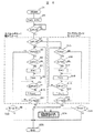
図1は、視覚障害者自動認識および視覚障害者運転モードを持ったエレベータシステムの例を示す。
【0035】
エレベータ1のかご13内には扉8、行先階表示板9、操作盤10が設けられ、操作盤10上には視覚障害者などのために音声案内装置(視覚障害者用音声案内装置12)、行先階ボタン11などが設けられる。エレベータの運転制御のために使用されるエレベータ制御装置2が設けられる。エレベータ制御装置2はホール側の操作盤5からの入力値を設け、エレベータかご13の現在位置あるいは予約状況を入力して運転をつかさどる運転コントローラ4を有する。運転コントローラ4とマイコン3とは一体的に表現される場合もある。ホール側の操作盤5はフェースプレート部6および乗り場ボタンであるエレベータ呼びボタン(上り)およびエレベータ呼びボタン(下り)7からなる。フェースプレート部6は人が触れた時に、それを電気的に検知することができるように検知装置14に接続し、検知信号をマイコン3に入力できるようにしておく。エレベータ呼びボタン(上り)およびエレベータ呼びボタン(下り)7に対する触手検知としてもよい。ここでは、フェースプレート部およびエレベータ呼びボタン(上り)およびエレベータ呼びボタン(下り)についての触手検知をフェースプレートに対する触手検知と総称する。
【0036】
視覚障害者は一般的に、両手を使いながら、フェースプレート部6の一部(主に端面部)を基準点として片手を置いておき、もう一方の利き腕の手で触覚情報をさがしていく。途中階では上行きと下行きの乗り場ボタン7があるため、視覚障害者は、2つのボタンの位置関係を確認した上で、どちらかを選択する。
【0037】
つまり、フェースプレート部6上に指先を触れながら探して行き、上下の2つのボタンにそれぞれ触れ、また触れてからある一定時間内にどちらかを押した場合に視覚障害者とみなすことができる。晴眼者の場合は、上下のボタンを見て確認できるため、両方のボタンをそれぞれ触れるという動作は通常行わない。この動作の違いにより抽出される情報から視覚障害者情報と晴眼者情報を判別することができる。
【0038】
視覚障害者のボタン触手による認知パターンの例を途中階、上行きの乗り場ボタンを押す場合を一例に取って説明する。図2は、視覚障害者のボタンの認知パターンの一例を示す。
【0039】
(1)両手を使って、乗り場ボタン7があると思われるフェースプレート部6を探す。端面21によりそれらしい形状を理解し、認識する。
【0040】
(2)一方の手22をフェースプレート部6上に静止させ(触手検知状態の継続)、もう一方の手23で乗り場ボタン7を探す。一方の手で順次上側の乗り場ボタンを確認(図面上で黒色で示す。以下同じ。)し、次に下側の乗り場ボタンを確認する。触手検知状態の継続は視覚障害者認識に当って重要な信号として利用し得る。
【0041】
(3)見つけた乗り場ボタン7の位置からもう一方の手23を上下させてもう一つのボタンを探す。下にもう一つのボタンがあることを確認する。そして、上にもう一つのボタンがあることを確認する。この状態では手22はフェースプレート部6に触っている。
【0042】
(4)上下に二つのボタンを確認したため、上側のボタンが上行きと判断し、それを押す。すなわち、エレベータ呼びボタン(上り)またはエレベータ呼びボタン(下り)に対する押圧を検知したことを条件として視覚障害者が利用者であると認識することができる。ホール側の操作盤のエレベータ呼びボタン(上り)およびエレベータ呼びボタン(下り)の双方がフェースプレート部6のタッチ状態の検知の下に順次タッチされたことをもとに視覚障害者の利用であると認識するものであってもよい。
【0043】
乗り場ボタンあるいは行先階ボタン(操作ボタン)の配設されるフェースプレート部に対する二つの触手検知があったことが視覚障害者であるかの認知の条件とされる。
【0044】
途中階の乗り場ボタンをタッチセンサーもついたストロークセンサーボタンとし、ボタンに触れた情報、押した情報と時間の関係をそれぞれ計算してその結果、視覚障害者かどうかを判別するようにする。
【0045】
論理としては、まずいずれかのボタンに触れた(直接押された場合も含む)瞬間から判定をスタートさせる。そして、上下二つのボタンが触れられたあとに、上下いずれかのボタンが押された場合には、視覚障害者のボタン検索行動から視覚障害者と判別する。片方のボタンしか触れられずにそのボタンを押された時は晴眼者と判別することになる。このように、触手検知の認識手段は、フェースプレート部やフェースプレート部上のある特定設定部、ボタン表面部などの触れた場所、触れた場所の順番、触れていた時間、乗り場ボタンへの触手、触手検知が始まってから、あるいは触手検知が終わってから乗り場ボタンの押されるまでの時間などから論理的に視覚障害者判定を行う。視覚障害者と判別した場合は視覚障害者モードへと移行する。視覚障害者モードによるエレベータの動作およびモード解除については後述する。
【0046】
また、視覚障害者がボタンを検索中、途中で気を変えてエレベータの使用を止めるためフェースプレート部6上のタッチを止める場合もあるので、ボタンに触れ、再びボタンから離れてから一定時間を過ぎても触れなかった、またはストロークが押されなかったときに判定をストップしてリセットするための設定制限時間Tlimitを設けるものとする。すなわち、Tlimitは視覚障害者がボタンを押さずに操作をやめた後、次に晴眼者等がボタン操作に入るまでに判定をリセットするかどうかの定数であるので、数秒という比較的短い時間を検索モードとして設定しておけばよい。本実施例では、Tlimitを3秒に設定する。
【0047】
なお、前提として一人の人間は誤操作しない限り、ストロークボタンは通常、ひとつしか押さない筈なので、ストロークボタンが押されるごとに論理判定はリセットされるものとする。
【0048】
図3は、ボタン回路センサ図を示す。操作盤5の乗り場ボタン7はタッチセンサ+ストロークセンサボタンとして構成される。
【0049】
図において、
A,C:タッチセンサー回路出力
誘導電流方式などで、ボタン表面に触れているかどうかを認識できる一般的なタッチセンサーボタンの回路。
触れている時をONとする。
B,D:ストロークセンー回路出力
ボタンを数ミリ程度押しこむことで、接点がオンする一般的なストロークボタンの回路。
接点がつながった時をONとする。
E:AとCのオア出力
F:BとDのオア出力
【0050】
ここでは、次ぎに示す論理のフローを解説するために、EとF(オア回路)を記述したが、実際にはA、B、C、Dのそれぞれの回路出力の線が論理を判定するマイコン(タイマー等を含む)の入力となっており、そのマイコンの中で計算されればよく、マイコンの外部にこのようなオア回路がある必要はない。
【0051】
また、乗り場ボタンが直接押された場合、まずタッチセンサー回路の出力がONし、その後ストロークセンサー回路の出力がONする論理とする。
【0052】
図4は、視覚障害者認識回路の1つのフローを示す。図において、Tはタイマー、Tlimitは人がボタンに触れた後、離れてから一定時間が過ぎても、触れない、または、ストロークが押されなかったときに判定をストップしてリセットするための設定制限時間を表わし、Rは両方のボタンに触れたかどうかのフラグで、両方に触れた時、R=1、それ以外はR=0で表わされる。
【0053】
また、図において、S4〜S11は先に上のボタンに触れたケース、S15〜S21は先に下のボタンに触れたケースを示す。TカウントはTの時間をカウントすることを示す。
【0054】
図において、T>Tlimitである場合(S11、S21)にはEND(S25)になり、R=1になる場合(S22、S23)に視覚障害者が利用者と認識し、視覚障害者運転モードS24によってエレベータは運転される。
【0055】
図5は、視覚障害者認識後のモード設定および解除の動作を示す。図に示すように、例として2階で視覚障害者Aが乗り込み、5階を登録、同じ階で乗り込んだ晴眼者Bは6階を登録、3階で晴眼者Cが乗ってきて7階を登録した場合を示す。2〜6階が視覚障害者運転モードになる。図の右に視覚者運転モードの運転状態を示す。
【0056】
視覚障害者と認識した場合は、その呼びボタンで動作するエレベータを視覚障害者モードに設定する。そのタイミングは、視覚障害者と判別する乗り場ボタンが押された時点から視覚障害者モードに設定し、呼ばれた方向のエレベータが到着し、その階床においてエレベータ内の操作パネルで押された行先階ボタンの最上階(上行き)または最下階(下行き)に到着し、エレベータの扉が開き閉じるまでとする。閉じた時点で視覚障害者モードを解除する。これは、視覚障害者と認識されても、同階で他人の人が乗り込み、エレベータ内で押された複数の行先階がある場合には、視覚障害者がどの行先階ボタンを押したか、特定が困難なためである。
【0057】
エレベータ内の操作パネルにもある種の視覚障害者認識機能を設置すれば特定は可能である。
【0058】
次に視覚障害者運転モード時の動作例を示す。
【0059】
視覚障害者と認識した場合のエレベータ側の動作としては、視覚障害者に配慮した音声案内情報の提供、扉の開閉時間制御など物理的な機械制御が有効と考えられる。視覚障害者に配慮した情報とは、エレベータの運転状況、動作や機能の説明、フロア案内、人の乗降、ドアの開閉情報、操作盤の使い勝手、昇降中の現在階情報、非常時の対応情報などである。
【0060】
1)扉開放時間の延長
視覚障害者がゆったりと乗り降りできるように通常時よりもエレベータ扉開放時間を延長する。
(例)通常5秒→視覚障害者モード時は15秒
【0061】
2)一定時間待機機能
通常、エレベータを呼んで乗り込んでも行先階が登録されないと、他の階でエレベータが呼ばれると、そちらへ動きだす。視覚障害者は、行先階の登録に時間がかかると予想され、このような予期しない方向へエレベータが動作する可能性がある。そこで、視覚障害者が乗り込み、エレベータ内の操作盤の行先階を登録するまでの時間を確保するために一定時間、そのフロアでエレベータを待機状態(行先階入力待ち)にさせる。一定時間よりも経過、または行先階が登録されたら待機を解除する。
(例)一定時間の設定は10秒程
【0062】
3)乗り場音声付加案内情報
○乗り場ボタンが押された後、乗り場でエレベータが来るまでの時間
機器構成:乗り場音声案内装置
・乗り場ボタンに対し目的のエレベータがある場所の情報(復数基ある場合)
理由:ひとつの乗り場ボタンで複数のエレベータを制御している場合が、視覚障害者にはどちらにあるのか、どちらのレベータが目的の階に向かうのかわからない。
例「向かって左側のエレベータをお待ち下さい」
・エレベータの運転階情報
理由:複数のエレベータがある場合、運転階床が制限されている場合がある。また、運転階床がわかれば、エレベータ内の操作パネルの行先階ボタンのレイアウトをイメージしやすい。
例「このエレベータは、○○階から○○階まで運転しております」
・エレベータ内の操作パネルの位置情報
理由:エレベータ内の操作パネルの位置は、機種によって異なるため、位置情報を流すことで視覚障害者にも操作パネルが探しやすくなる。
例「エレベータ内の操作パネルは、入って左側のそで壁にあります」
・エレベータの現在の運転状況
理由:エレベータを待つのは視覚障害者にとって不安が伴う。現在位置などを適宜知らせることで安心感が増す。また、店などの場合、フロア案内を付加することで、どの階に何があるかを知ることもできる。
例「エレベータは、現在3階婦人服売場に停止中です。まもなくまいります」
・扉の開閉、解放時間延長情報および乗り降り注意情報
理由:扉の開放時間が延長されることを知らせることで、精神的にもゆったりと対応するここができる。
例「ドアは約15秒開放いたします。ごゆっくりとお乗り込みください」
「ドアがひらきます。ご注意下さい」
「ドアが開きました。段差、隙間にご注意してお乗り込みください」
・人の乗り降り情報
理由:視覚障害者には乗り込む前に、降りる人がいるかどうか、またその人の動きがよくわからない。その階でエレベータから降りる人がいることを事前に知らせる(中の操作盤で行先階予約されていたことから認識できる)ことで、降りる人と不用意にぶつかるよなトラブルをさける。
例「この階で降りる人がいます。ご注意下さい」
【0063】
4)エレベータ内音声付加案内情報
視覚障害者がエレベータ利用者との認識をしたときに、視覚障害利用のホール階床を行先階ボタン11から検知し、その階床について音声による乗り場案内情報放送を行う。
・エレベータ内での情報
機器構成:エレベータ内音声案内装置
・現在階、フロア施設案内情報
理由:インジケータの表示が視覚障害者は認識できず、現在階やどの階に何があるのか分かりにくいことがある。また、非常時に有効な階段の場所やトイレの位置などがおおまかでも分かると安心できる。
例「3階婦人服売り場です。階段は右手、化粧室は左手奥にございます」
・非常時の対応情報
理由:故障などにより、エレベータが止まった場合の対応が視覚障害者には分かりにくいことがある。
例「非常時には操作盤上部にあるボタンを押しつづけてください。インターホンで…」
・扉の開閉および乗り降り注意情報
理由:扉の開閉情報を知らせることで、精神的にもゆったり乗り降りすることができる。エレベータとホールの隙間や段差の情報を知らせることで、安全な乗り降りを促すことができる。
例「ドアがひらきます。ご注意下さい」
「ドアが開きました。段差、隙間にご注意してお降りください」
【0064】
5)エレベータ内操作盤上行先階ボタン点滅機能
・視覚障害者を判別した階で押された行先階ボタンをその階の到着前に(例えば階に到着する2秒前から到着してドアが開きだす直前まで)点滅させる。
理由:弱視者の場合でも同様の視覚障害者として判別できる可能性がある。弱視の人の場合、音声案内のないエレベータで、インジケータが見えない場合は、自分が押した行先階ボタンの点灯と消灯をたよりに目的の階に到着したか否かを判断することもある。到着時に行先階を点滅させることで、自分の押した階が到着したことを弱視者にも分かり易くすることができると考える。
【0065】
6)音声案内注意喚起チャイム
・エレベータ内の音声案内で到着階、扉開閉など、視覚障害者にとって音声に頼る重要な案内を放送する直前に、これから音声案内が流れるという注意を喚起するチャイムを鳴らす。到着予報チャイムとは音色を変える。これによって聞き逃がしを防止することができる。
例:到着階「チーン」「3階です」
扉閉め「ブー」「扉がしまります」
【0066】
7)扉開閉チャイム
・扉は開閉の音声案内があっても、閉まり出すタイミングや開く状態がわかりにくいことがある。そこで、開閉動作中に適したチャイムを鳴らす。例えば、開く時は心地よい音。閉まるときはブザーのような少し不快な音。
【0067】
図6は、視覚障害者認識時の動作フローを示す。
【0068】
視覚障害者と認識した場合の動作フローをいくつかの動作例を元に具体的に示す。ここでは視覚障害者モードと通常モードの違いがわかりやすいように、対比して記述する。また、利用者の行動とエレベータ側の動作の機能例を
▲1▼扉開放時間の延長
▲2▼音声付加案内情報の提供
▲3▼音声案内注意喚起チャイム
について示す。詳細な内容は図に示される通りである。
【0069】
図7は、視覚障害者運転モードを備えたエレベータシステムの構成を示すブロック図である。
【0070】
乗り場側システム41は各階フロアについてボタンスイッチ42、マイコン43、音声出力装置44を備える。各エレベータ45は、音声出力装置46、扉開閉制御47のための扉開閉制御装置48およびマイコン49を備える。エレベータ45は、乗り場側システム41からの入力値およびエレベータ現状値を入力、処理、出力するエレベータ運転制御装置50により制御される。
【0071】
音声装置は、音声以外に、注意喚起報知音のような効果音出力も含む。この構成により、視覚障害者モード時の動作例を全て実現することができる。
【0072】
エレベータが運転する最上階および最下階では、途中階と違い、乗り場ボタンがひとつのため、これまでの認識方法では視覚障害者を判別することができない。そこで、これらの階については、実施例3のような認識システムを参考されたい。
【0073】
図8および図9は、視覚障害者自動認識方法についての実施例2を示す。
【0074】
図8は、ボタン回路センサ図であり、この例にあってはフェースプレート部6上にタッチセンサ51が設けられる。先の実施例におけるフェースプレート部6の機能はタッチセンサ51が探すことになる。すなわち、タッチセンサ51は、フェースプレート部6の一部を構成する。この場合、フェースプレート部6とタッチセンサ51とのANDを取るようにしてもよい。タッチセンサとしては、誘導電流型,赤外線検知,マイクロスイッチ型など一般に使用されているものが使用される。従って、触手検知には直接的に手を触れる場合と、間接的に手を触れる場合の双方を含む。
【0075】
視覚障害者はフェースプレート部6に触れ、次いで2つのストロークボタン52の間に設けたタッチセンサ51に触れることになる。
【0076】
図において、
A,B:ストロークセンサー回路出力
ボタンを数ミリ程度押しこむことで、接点がオンする一般的なストロークボタンの回路。
接点がつながった時をONとする。
C:タッチセンー回路出力
誘導電流方式などで、ボタン表面に触れているかどうかを認識できる一般触れている状態をONとする。
D:AとBのストロークオア出力
前記の視覚障害者のボタン検索の行動原理と応用、視覚障害者のボタンの認知パターンの一例の(4)に注目すると、この認知パターンでは、必ず上下のボタンの間を触れることになる。そこで、フェースプレート部上のこの2つのボタンの間にタッチセンサ51を設け、この部分に触れた情報と、ボタンを押した情報(と時間の関係)から視覚障害者かどうかを判別するようにしている。
【0077】
ここでは、次に示す論理のフローを解説するために、D(アオ回路)を記述したが、実際にはA、B、Cのそれぞれの回路出力の線が論理を判定するマイコン(タイマー等を含む)の入力となっており、そのマイコンの中で計算されればよく、マイコンの外部にこのようなオア回路がある必要はない。
【0078】
図9は、視覚障害者認識回路のフローを示す。フローはS31からS39までのステップからなる。
【0079】
図において、Tはタイマー、Tlimitは人がタッチセンサー部に触れて、離してから一定時間を過ぎても触れなかった、またはストロークが押されなかったときに判定をストップしてリセットするための設定制限時間。タッチセンサー部を限定しているため、この部分以外のフェースプレート部やボタン上に触れている場合も考えられるため、やや長めに設定する。ここでは、Tlimit=20秒に設定する。
【0080】
本方法では、実施例1よりも簡単な回路で実施する反面、タッチセンサー部には、晴眼者でも何気なく触れる可能性も高く、視覚障害者として判別できる確率は、実施例1よりも低くなる可能性がある。
【0081】
図10および図11は、実施例3を示す。図10は、ボタン回路センサーを示す。
【0082】
図において、フェースプレート部6の上部全面にタッチセンサ61が設けてある。すなわち、フェースプレート部をタッチセンサ61としている。他の構成およびフローは実施例2と同じである。62はストロークボタンである。
【0083】
尚、最下階乗り場ボタンは、図11に示すように構成し、図10と同様にタッチセンサー61、ストロークボタン62を設ける。
【0084】
実施例3の方法で、晴眼者が触れにくい部分はタッチセンサー部としない、また、視覚障害者が触れやすい部分を特定するという方法として以下に示す、各種のバリエーションが考えられる。このようなバリエーションの採用によって、前述した認識方法と組み合せることができ、視覚障害者との認識率を高めることができる。
【0085】
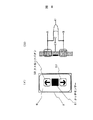
図12は、実施例4に関するボタン回路センサ図である。
【0086】
視覚障害者が、フェースプレート部6を探し当て、次にフェースプレート部上の乗り場ボタン7を探す際、ボタンを探す基準として固定しておく手がフェースプレート部のエッジ(端面部)71に触れているという行動に注目し、この部分をタッチセンサー部72とする。そして、この部分に触れてから、ストロークボタンが押されるまでに、触れていた合算時間がある一定時間以上なら視覚障害者と判別する。論理フロー図は、実施例3と同様である。この際は、最上階、最下階のボタンにも有効である。
【0087】
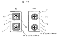
図13は、実施例5に関するボタン回路センサ図である。
【0088】
視覚障害者が、フェースプレート部6を探し当て、次にフェースプレート部上の乗り場ボタン7を探す際、指を滑らせるようにボタンの位置を探し当てる、つまり、ほぼ連続した軌跡でボタンに行きつく行動に注目し、ボタンの周辺部74をタッチセンサー74とする。(イ)は四角ボタン例、(ロ)は丸ボタンの例を示す。そして、この部分に触れた後、ストロークボタンが押された場合に視覚障害者と判別する。範囲を狭めることで、晴眼者がフェースプレート部6に自然に触れても晴眼者を視覚障害者と判別しない確率を上げることができる。論理フロー図は、実施例2と同様である。この例は、最上階、最下階のボタンにも有効である。
【0089】
図14は、実施例6に関するボタン回路センサ図である。
【0090】
点字銘板部をタッチセンサー部とする考えもあるが、晴眼者が点字銘板を興味本位に触れることがよくあり、このままでは判別が困難である。
【0091】
そこで点字を探す視覚障害者が触れながら探す行為に着目し、上下の点字銘板75の間、もしくはその周辺にタッチセンサー部76を設ける。そして、この部分に触れた後、ストロークボタンが押された場合に視覚障害者と判別する。晴眼者は、興味本位に触れるとしても、点字銘板部のみにそれぞれ触れ、このタッチセンサー部には触れないと考えられるからである。
【0092】
また、独立して検知できるタッチセンサー部を点字名板部にも設け、それぞれ触れた情報を計算することで判別の確率を上げることも可能と考えられる。論理フロー図は、実施例2と同様である。
【0093】
図15および図16は、エレベータ内での視覚障害者自動認識と動作とを示す。図15は行先階ボタン回路センサ図である。
【0094】
図において、操作盤10のフェースプレート部81、上には行先階ボタン11が設けられている。この行先階ボタン11がタッチセンサ+ストロークセンサーボタンの機能を果す。認知パターンは、図2と同様である。これまでは、エレベータホールにおける視覚障害者の自動認識および動作であるが、エレベータに乗り込んでから、行先階などを指定する視覚障害者の検索行為に着目して、自動認識できれば、行先階ボタンが押された時の視覚障害者の特定、エレベータ内は暗い場合があるので、弱視の人も同様の検索行為を行うとすれば、視覚障害者として特定できるの範囲を広げられ、より多くの視覚障害者に、エレベータの使い勝手を向上させる手段を提供できる。
【0095】
自動認識の原理は、乗り場ボタンの時の実施例を応用して判別できる。例えば、実施例1のように、タッチセンサー+ストロークセンサーボタンをエレベータ内の操作パネルの行先階ボタンに用いる。視覚障害者(点字を読まない人)は、自分が目標とする階を、操作盤にあるボタンの数や一般的な慣習に基づく配列をイメージしながら、例えば左下から1、2、3・・・と順次探していく。このため、近接した複数の行先階ボタンに触れることが多い。
【0096】
そこで、行先階ボタンに触れた情報と、その後でストロークにより押された情報と時間の関係から、ある時間内に近接(連続した)複数の行先階ボタンに触れたこと、そのあとでボタンが押された場合、その行先階ボタンが視覚障害者の目的階であると判別することができる。
【0097】
図16は、視覚障害者認識回路のフローを示す。フローはS41からS52のステップからなる。
【0098】
図において、
Jは(直前と異なる)SNを記憶する1次行列である。
Sをタッチセンサーとして触れた(ON)出力情報とする。
(SNは触れた行先階ボタンの階)
Pを行先階ボタンがストロークで押された出力情報とする。
(PNは押された行先階ボタンの階)
Tはタイマー。Tlimitは人がボタン上に触れて、離してから一定時間を過ぎても触れなかった、またはストロークが押されなかったときに判定をストップしてリセットするための設定制限時間。
【0099】
ここでは、Tlimit=3秒程度に設定する。
【0100】
PとJの比較すなわち設定条件との比較(S50)に当って、記憶された一次行列Jの最後から2番目のSNが、(PN+1)か(PN−1)のとき(すなわち押されたボタンの直前に上か下の階のボタンに触れた場合)、YESとする。それ以外はNOとする。すなわち、視覚障害者と認識する。
【0101】
(例)PN=6、J=(6)→晴眼者
PN=6、J=(12、6)→晴眼者(6階を押そうとして12階のボタンに触れた可能性がある)
PN=6、J=(2、1、2、3、4、5、6)→視覚障害者(6階を押す前に5階のボタンに触れている)
【0102】
このようにエレベータ内の操作盤の自動認識において視覚障害者と認識した場合、その時点から視覚障害者モードに設定し、乗り場ボタンで認識した際の「視覚障害者モード時の動作例」に示したような動作を行うものとする。
【0103】
ただし、視覚障害者の行先階が特定できることとし、上記で設定した行先階に到着し、ドアが開閉した後に視覚障害者モードを解除する。
【0104】
また、音声案内装置が具備されている場合は、次のような機能を付加することも可能である。すなわち、エレベータ内の操作盤の行先階ボタンにおいて、ストロークが押されることなく、ある一定時間内に行先階ボタンが複数(例えば3つ以上)触れられた場合には、触れている人が視覚障害者であると認識して(確率が高い)、その時点から、触れているボタンの階の数字を音声出力すれば、視覚障害者はどの行先階ボタンに触れているかを知ることができ、目的のボタンを正確にかつ迅速に探すことが可能となるであろう。
【0105】
もちろん、検索後に行先階を押した場合、(例)「6階を登録しました」等の音声案内が出るとなお便利であることはまちがいない。
【0106】
エレベータ内の操作盤における、視覚障害者の認識方法については、上記以外にも、乗り場の操作盤と同様に、
・行先階ボタンをタッチセンサー&ストロークボタンとし、複数(例えば3つ)以上のボタンに触れた後にボタンが押された場合
・エレベータ内操作盤のフェースプレート部全面をタッチセンサーとし、ある一定時間以上触れていた後にボタンが押された場合
・点字銘板部間のフェースプレート部をタッチセンサーとし、ここに触れた後にボタンが押された場合
・点字銘板部をタッチセンサーとし、点字部に触れた後にその点字に対応するボタンが押された場合
等を、視覚障害者として認識することが可能である。
【0107】
【発明の効果】
本発明によれば、視覚障害者がまず触れることなり、かつ一方の手でかつ継続して触れることになるフェースプレートに対する触手状態を検知し、これを1つの条件とし、他の触手状態を他の条件としてAND信号があったときに視覚傷害者が利用者であるとの認識を行うようにしているので、更には、操作ボタンが押圧されるまでの時間を求めて論理的に視覚障害者であるとの認識を行うようにすることができるので、視覚障害者の操作ボタン探索の行動に沿って視覚障害者が利用者であるとの判別をすることになるから視覚障害者自動認識が確実に行われることになる。これに伴なって高い認識率の下にエレベータの運転を視覚障害者運転モードに移行せしめることができるから扉開放時間の延長、音声付加案内情報の提供、音声案内注意喚起チャイムなどのサービスを確実に行うことが出来るようになる。また、これに伴なって、視覚障害者運転モードによって通常運転時の運転効率を落とさずに済み、また周りの人たちへの音声ノイズを減らすことができる。
【図面の簡単な説明】
【図1】本発明の実施例にかかわるエレベータシステム構成図。
【図2】視覚障害者のボタン認知パターン図。
【図3】ボタン回路センサ図。
【図4】視覚障害者認識フローチャート図。
【図5】視覚障害者認識後のモード設定および解除の動作図。
【図6】視覚障害者認識時の動作フローチャート図。
【図7】エレベータシステムの構成を示すブロック図。
【図8】他のボタン回路センサ図。
【図9】視覚障害者認識回路のフローチャート図。
【図10】他のボタン回路センサ図。
【図11】最下階乗り場ボタン図。
【図12】他のボタン回路センサ図。
【図13】他のボタン回路センサ図。
【図14】他のボタン回路センサ図。
【図15】行先階ボタン回路センサ図。
【図16】視覚障害者認識回路のフローチャート図。
【符号の説明】
1…エレベータ、2…エレベータ制御装置、3…マイコン、4…運転コントローラ、5…操作盤、6…フェースプレート部、7…乗り場ボタン、8…扉、9…行先階表示板、10…操作盤、11…行先階ボタン、12…視覚障害者用音声案内装置、13…かご、14…検知装置、61…タッチセンサ、81…フェースプレート部[0001]
BACKGROUND OF THE INVENTION
The present invention relates to an elevator operation control apparatus suitable for use by visually impaired persons.
[0002]
[Prior art]
Japanese Patent Application Laid-Open No. 7-206290 describes that a dedicated hall button for visually handicapped persons is provided, and a broadcasting facility is provided for notifying elevator users of the car call registration status by linking these buttons.
[0003]
Japanese Patent Application Laid-Open No. 9-110319 includes a call registration device in a hall and a car, and in an elevator of an automatic driving system equipped with a Braille plate expressed in Braille so that a visually impaired person can operate the call registration device, A sensor for detecting that a human body has come into contact with the Braille board, and the Braille content of the touched Braille nameplate is broadcasted by voice by a voice guidance device according to the sensing signal. An apparatus is described.
[0004]
Japanese Patent Application Laid-Open No. 8-34581 discloses a braille nameplate that detects that an elevator user has touched, and a button switch that is pressed within a predetermined time after detecting that the braille nameplate is touched. When this is detected, there is described a control device for an elevator, comprising door opening time extension means for sending a door opening time extension signal to the door electric opening and closing device.
[0005]
[Problems to be solved by the invention]
The prior art includes the following problems.
・ It is difficult for visually impaired people to understand the opening and closing of doors and the current floor. Some voice guidance devices are installed, but they do not always provide sufficient content. Conversely, if the office is close to the elevator installation, the voice guidance is changed and the person who works in the office. May cause audio noise.
・ If there is a visual impairment, it may take time to get on and off the elevator and operate, and if the door opening and closing time is short, it is difficult to get on and off in accordance with the door opening and closing timing.
・ If there are multiple elevators in the elevator hall, it may be difficult to know which elevator has arrived due to echoing the hall even if there is a voice guidance device.
・ There is an invention that automatically recognizes people who touch the braille nameplate as visually impaired people, but the percentage of visually impaired people who can read braille is low, and there are quite a few visually impaired people who do not even touch the braille nameplate. it is conceivable that.
[0006]
In view of such a point, the present invention reliably determines whether the user is visually impaired or not according to the behavior of elevator call or destination floor button search when the visually impaired uses the elevator. Provided an elevator operation control device that recognizes people with disabilities and does not reduce the driving efficiency during normal driving by the visually impaired driving mode, and can reduce voice noise to people around. The purpose is to do.
[0007]
[Means for Solving the Problems]
Tactile sensors are provided on the operation panel that calls the elevator in the elevator hall, the operation buttons on the operation panel in the elevator, and the face plate, and the visually impaired person automatically recognizes the visually impaired person by sensing the action of searching for the button. . Thereby, the operation | movement (usability) of the elevator suitable for the condition of an elevator and a visually handicapped person can be provided to a visually handicapped person. Here, the elevator call button (up) and the elevator call button (down) are collectively referred to as a landing button, and the landing button and the destination floor button are collectively referred to as an operation button.
[0008]
・ The visually handicapped person searches for the desired operation button while confirming the number and position of the face plate and buttons. Paying attention to this series of actions and the touched part, it is determined whether or not the person is visually impaired from the relationship between the touched part, the pressed button, and the timing.
[0009]
When it is determined that the person is visually impaired as described above, it is possible to extend the door opening time or add audio information that is optimal for the visually impaired person, thereby improving the usability of the visually impaired person.
[0010]
・ By automatic recognition, only when using visually impaired people, it is possible to operate the above functions as a visually impaired person mode so that the driving efficiency during normal driving is not reduced. It can be reduced to the minimum.
[0011]
-With the above method, visually impaired persons who do not read Braille, that is, do not rely on Braille nameplates, can be distinguished from visually impaired persons, and the usability of more visually impaired persons can be improved.
[0012]
・ Because there is no special button for visually handicapped people, there is the merit that it does not lead to a special view of a healthy person for a handicapped person without confusion as tactile information.
[0013]
・ Because it can be constructed with the application of conventional technology and a simple system, cost increases can be suppressed.
[0014]
For example, a landing button on the middle floor is a stroke button with a touch sensor, and the relationship between touched information and time is calculated to determine whether or not the person is visually impaired. When it is determined that the person is visually impaired, the control of the elevator is changed to extend the door opening / closing time or add audio information optimal for the visually impaired. In addition, the face plate can be used as a touch sensor, and the touched part can be identified to identify the visually impaired person.
[0015]
Specifically, the present invention provides the following apparatus.
[0016]
The present inventionA hall-side operation panel provided in an elevator hall with a landing button and an elevator with an elevator operation control device that controls the operation of the elevator based on the operation of the landing button, wherein the hall-side operation panel has a face plate portion And a landing button provided on the face plate portion for detecting an operation pressed by the user, and a touch sensor provided so as to surround the landing button and detecting an operation touched by the user, The elevator operation control device includes a normal operation mode and a visually impaired person operation mode, and when the touch sensor is touched and detects that the landing button is pressed within a certain period of time, the visually impaired person The operation is determined to be an operation and the driving is controlled in the visually impaired driving mode, and the landing button is directly pressed. Elevator and controlling the operation in the normal operation mode when it detects that it has beenI will provide a.
[0017]
The present inventionThe elevator operation control device includes an in-car operation panel provided with a destination floor button in the elevator car, and the elevator operation control device, when the visually impaired person operation mode is determined, determines the elevator in the direction called by the operation of the landing button. Arrives at the top or bottom floor set in the floor via the destination floor button, continues until the elevator door opens and closes, and is released when the door is closed Elevator featuresI will provide a.
[0018]
The present inventionThe elevator car includes a destination floor button and an operation panel in the car provided with a voice guidance device, a hall voice guidance device is provided in the elevator hall, and the elevator operation control device is in the visually impaired person operation mode,
(1) Extending door opening time to extend the opening time of elevator doors during normal operation,
(2) A fixed time standby function for waiting for destination floor input by the destination floor button for a fixed time on the floor determined to be operated by a visually impaired person;
(3) A platform voice additional guidance information function for performing voice guidance of additional information until an elevator arrives at a floor platform determined to be operated by a visually impaired person,
(4) In the elevator, at least one of the in-elevator voice additional guidance information functions for performing voice guidance of additional information until the disabled person operation mode is canceled from the floor determined to be operated by the visually impaired Elevator characterized byI will provide a.
[0019]
The present invention further includesThe hall button has a circular appearance shape, and the touch sensor is arranged so as to surround the circle hall button.I will provide a.
[0033]
DETAILED DESCRIPTION OF THE INVENTION
Embodiments of the present invention will be described below with reference to the drawings.
[0034]
FIG. 1 shows an example of an elevator system having a visually impaired person automatic recognition and a visually impaired driving mode.
[0035]
A
[0036]
A visually handicapped person generally uses one hand to place one hand with a part of the face plate part 6 (mainly the end face part) as a reference point and looks for tactile information with the other hand. Since there are up and down
[0037]
That is, it can be regarded as a visually handicapped person when searching while touching the fingertip on the
[0038]
An example of a recognition pattern using a button tentacle of a visually handicapped person will be described by taking as an example a case where an upstairs landing button is pressed. FIG. 2 shows an example of a button recognition pattern of a visually impaired person.
[0039]
(1) Using both hands, search for the
[0040]
(2) One
[0041]
(3) The
[0042]
(4) Since the upper and lower buttons are confirmed, it is determined that the upper button is going up, and it is pushed. That is, it is possible to recognize that the visually handicapped person is a user on condition that a press on the elevator call button (up) or the elevator call button (down) is detected. The use of the visually impaired person based on the fact that both the elevator call button (up) and the elevator call button (down) on the operation panel on the hall side are sequentially touched under detection of the touch state of the
[0043]
The detection of two tentacles on the face plate portion where the landing button or the destination floor button (operation button) is arranged is a condition for recognizing whether the person is visually impaired.
[0044]
The platform button on the middle floor is a stroke sensor button with a touch sensor, and the information on touching the button, the relationship between the pressed information and the time are calculated, and as a result, it is determined whether the person is visually impaired.
[0045]
As a logic, first, the determination is started from the moment when one of the buttons is touched (including when it is directly pressed). Then, if any one of the upper and lower buttons is pressed after the two upper and lower buttons are touched, it is determined that the visually impaired person is a visually impaired person based on the button search behavior of the visually impaired person. When only one of the buttons is touched and the button is pressed, it is determined that the person is sighted. As described above, the recognition means for detecting the tentacles includes the face plate part, a specific setting part on the face plate part, the touched place such as the button surface part, the order of the touched place, the touched time, and the tentacles to the landing button. The visually handicapped person is logically determined from the time until tentacle detection is started or after the tentacle detection is completed until the landing button is pressed. When it is determined that the user is visually impaired, the mode is shifted to the visually impaired mode. The elevator operation and mode cancellation in the visually impaired person mode will be described later.
[0046]
In addition, when a visually impaired person searches for a button, the touch on the
[0047]
Note that, as a premise, unless one person mistakenly operates, the stroke button is normally only pressed by one person, so that the logic judgment is reset every time the stroke button is pressed.
[0048]
FIG. 3 shows a button circuit sensor diagram. The
[0049]
In the figure,
A, C: Touch sensor circuit output
This is a general touch sensor button circuit that can recognize whether the button surface is touched by an induced current method.
Turn on when touching.
B, D: Stroke sensor circuit output
A general stroke button circuit in which the contact is turned on by pressing the button several millimeters.
Turn on when contact is connected.
E: OR output of A and C
F: OR output of B and D
[0050]
Here, in order to explain the logic flow shown below, E and F (OR circuit) are described, but in reality, each of the circuit output lines A, B, C, and D determines the logic. It is only necessary to calculate within the microcomputer, and there is no need for such an OR circuit outside the microcomputer.
[0051]
In addition, when the landing button is pressed directly, the output of the touch sensor circuit is turned on first, and then the output of the stroke sensor circuit is turned on.
[0052]
FIG. 4 shows one flow of the visually impaired person recognition circuit. In the figure, T is a timer, and Tlimit is a setting to stop and reset the judgment when a person has touched the button, but it has not touched or the stroke has not been pressed even if a certain time has passed after leaving the button. R represents a time limit, and R is a flag indicating whether or not both buttons have been touched. When both are touched, R = 1, otherwise R = 0.
[0053]
In the figure, S4 to S11 indicate cases where the upper button is first touched, and S15 to S21 indicate cases where the lower button is first touched. T count indicates that the time of T is counted.
[0054]
In the figure, when T> Tlimit (S11, S21), END (S25) is obtained, and when R = 1 (S22, S23), the visually handicapped person recognizes the user and the visually handicapped person driving mode. The elevator is operated by S24.
[0055]
FIG. 5 shows operations for mode setting and cancellation after recognition of the visually impaired. As shown in the figure, as an example, visually impaired person A gets on the second floor, registers the fifth floor, sighted person B who gets on the same floor registers the sixth floor, and sighted person C gets on the third floor and the seventh floor Indicates the case of registration. The 2nd to 6th floors are in visually impaired driving mode. The driving state in the viewer driving mode is shown on the right side of the figure.
[0056]
If it is recognized that the person is visually impaired, the elevator operated by the call button is set to the visually impaired mode. The timing is set to the visually impaired mode from the point when the landing button that identifies the visually impaired person is pressed, the elevator in the called direction arrives, and the destination that is pressed on the operation panel in the elevator on that floor Suppose you arrive at the top floor (up) or bottom floor (down) of the floor button until the elevator door opens and closes. Cancel the visually impaired mode when closed. Even if it is recognized as a visually handicapped person, if there is more than one destination floor boarded by another person on the same floor and pressed in the elevator, specify which destination floor button the visually handicapped person pressed. This is because it is difficult.
[0057]
Identification is possible if a certain kind of visually impaired person recognition function is installed on the operation panel in the elevator.
[0058]
Next, an example of operation in the visually impaired driving mode is shown.
[0059]
As an operation on the elevator side when it is recognized as a visually handicapped person, physical machine control such as provision of voice guidance information in consideration of the visually handicapped person and door opening / closing time control is considered to be effective. Information that considers visually impaired people includes elevator operation status, explanation of operations and functions, floor guidance, people getting on and off, door opening and closing information, operation panel usability, current floor information during ascent and descent, emergency response information Etc.
[0060]
1) Extension of door opening time
The elevator door opening time will be extended more than usual so that visually impaired people can get on and off comfortably.
(Example) Normal 5 seconds → Visually
[0061]
2) A fixed time standby function
Normally, if the destination floor is not registered even if the elevator is called and boarded, when the elevator is called on another floor, it will move to that floor. A visually impaired person is expected to take time to register the destination floor, and the elevator may move in such an unexpected direction. Therefore, in order to secure the time until the visually impaired person gets in and registers the destination floor of the operation panel in the elevator, the elevator is put in a standby state (waiting for destination floor input) for a certain time. The waiting is canceled when a certain time has elapsed or the destination floor is registered.
(Example) The fixed time is set to about 10 seconds.
[0062]
3) Platform audio additional guidance information
○ Time from when the platform button is pressed until the elevator arrives at the platform
Equipment configuration: Platform voice guidance device
-Information on the location where the target elevator is located for the landing button (if there are reciprocal units)
Why: If you use a single landing button to control multiple elevators, visually impaired people don't know where they are and which one goes to the target floor.
Example "Please wait for the elevator on the left"
・ Elevator operation floor information
Reason: If there are multiple elevators, the operation floor may be restricted. If the operation floor is known, it is easy to imagine the layout of the destination floor buttons on the operation panel in the elevator.
Example “This elevator operates from the XX floor to the XX floor”
・ Position information of the operation panel in the elevator
Reason: Since the position of the operation panel in the elevator varies depending on the model, it is easy for visually impaired people to search for the operation panel by flowing position information.
Example “The control panel in the elevator is on the left side wall after entering”
・ Current operating status of elevators
Reason: Waiting for the elevator is anxious for the visually impaired. A sense of security is increased by notifying the current location as appropriate. In addition, in the case of a store or the like, it is possible to know what is on which floor by adding floor guidance.
Example “Elevator is currently stopped at the 3rd floor women ’s clothing department.
-Opening / closing doors, extended release time information, and getting-on / off warning information
Reason: By informing you that the opening time of the door will be extended, you can respond here mentally and comfortably.
Example “The door will be open for about 15 seconds.
"The door opens. Please be careful."
"The door has opened. Please be careful of the gap and gap"
・ Human information
Why: Visually impaired people don't know if anyone gets off before getting in and how the person moves. By notifying in advance that there are people getting off the elevator on that floor (it can be recognized from the fact that the destination floor has been reserved on the inside control panel), it avoids the trouble of accidentally colliding with the person getting off.
Example "There are people getting off on this floor. Please be careful"
[0063]
4) Elevator voice additional guidance information
When a visually handicapped person recognizes that he / she is an elevator user, the hall floor using the visually handicapped is detected from the
・ Information in the elevator
Equipment configuration: Elevator voice guidance device
・ Current floor, floor facility information
Reason: The display of the indicator cannot be recognized by visually impaired people, and it may be difficult to understand what is on the current floor or which floor. Also, if you know roughly the location of stairs and toilets that are useful in an emergency, you can feel secure.
Example “3rd floor ladies' clothing store. The stairs are on the right and the restroom is on the left.”
・ Emergency response information
Reason: It may be difficult for visually impaired people to understand when the elevator stops due to a malfunction.
Example “In an emergency, keep pressing the button on the top of the control panel.
・ Door opening / closing and getting-on / off warning information
Reason: You can get on and off mentally by notifying the door opening / closing information. It is possible to encourage safe boarding / exiting by notifying information on gaps and steps between the elevator and the hall.
Example “The door opens. Please be careful”
"The door has opened. Please be careful not to get off the steps or gaps."
[0064]
5) Elevator operation panel upper destination floor button flashing function
-The destination floor button pressed on the floor where the visually impaired person is identified blinks before the arrival of that floor (for example, from 2 seconds before arrival on the floor until just before the door opens).
Reason: There is a possibility that even a visually impaired person can be identified as a visually impaired person. In the case of a low-sighted person, if the indicator is not visible in an elevator without voice guidance, it may be determined whether or not the destination floor has been reached rather than turning on and off the destination floor button that the user has pressed. By flashing the destination floor when arriving, it is possible to make it easier for low-sighted people to understand that the floor they pressed has arrived.
[0065]
6) Voice guidance warning chime
・ Sounds a chime to call attention that voice guidance will flow immediately before broadcasting important guidance that depends on voice for visually impaired people, such as arrival floor, door opening and closing, etc. by voice guidance in the elevator. The arrival forecast chime changes the tone. This prevents missed listening.
Example: Arrival floor "Chen" "3rd floor"
Door closed "Boo" "Door closes"
[0066]
7) Door open / close chimes
・ Even if there is a voice guidance for opening and closing the door, it may be difficult to understand when it closes and when it opens. Therefore, a suitable chime is sounded during the opening / closing operation. For example, a pleasant sound when opening. A little unpleasant sound like a buzzer when closing.
[0067]
FIG. 6 shows an operation flow when recognizing a visually impaired person.
[0068]
The operation flow when it is recognized as a visually handicapped person will be specifically shown based on several operation examples. Here, the difference between the visually impaired person mode and the normal mode is described so that it can be easily understood. In addition, functional examples of user behavior and elevator operation
(1) Extension of door opening time
▲ 2 ▼ Provision of additional voice guidance information
(3) Voice guidance alert chime
Show about. The detailed contents are as shown in the figure.
[0069]
FIG. 7 is a block diagram showing a configuration of an elevator system having a visually impaired driving mode.
[0070]
The landing-side system 41 includes a
[0071]
The sound device includes a sound effect output such as a warning sound in addition to the sound. With this configuration, it is possible to realize all operation examples in the visually impaired person mode.
[0072]
Unlike the middle floor, the top and bottom floors operated by the elevator have a single landing button, so that the conventional recognition methods cannot identify visually impaired persons. Therefore, for these floors, please refer to the recognition system as in the third embodiment.
[0073]
8 and 9 show a second embodiment of the method for automatically recognizing the visually impaired.
[0074]
FIG. 8 is a button circuit sensor diagram. In this example, a
[0075]
The visually impaired person touches the
[0076]
In the figure,
A, B: Stroke sensor circuit output
A general stroke button circuit in which the contact is turned on by pressing the button several millimeters.
Turn on when contact is connected.
C: Touch sensor circuit output
A general touching state that can recognize whether or not the button surface is touched by an induced current method or the like is set to ON.
D: A or B stroke or output
When attention is paid to the action principle and application of the button search for the visually impaired and the example (4) of the recognition pattern of the button of the visually impaired, in this recognition pattern, the upper and lower buttons are always touched. Therefore, a
[0077]
Here, in order to explain the logic flow shown below, D (Ao circuit) has been described, but in reality, each of the circuit output lines A, B, and C determines the logic (such as a timer). It is only necessary to be calculated in the microcomputer, and there is no need for such an OR circuit outside the microcomputer.
[0078]
FIG. 9 shows a flow of the visually impaired person recognition circuit. The flow includes steps from S31 to S39.
[0079]
In the figure, T is a timer, and Tlimit is a setting for stopping and resetting the judgment when a person touches the touch sensor unit and does not touch even after a certain period of time has passed since it was released, or when the stroke is not pressed Time limit. Since the touch sensor part is limited, it may be possible to touch a face plate part or button other than this part, so it is set a little longer. Here, Tlimit = 20 seconds is set.
[0080]
Although this method is implemented with a simpler circuit than that of the first embodiment, there is a high possibility that even a sighted person will casually touch the touch sensor unit, and the probability that it can be determined as a visually impaired person may be lower than that of the first embodiment. There is sex.
[0081]
10 and 11 show a third embodiment. FIG. 10 shows a button circuit sensor.
[0082]
In the figure, a touch sensor 61 is provided on the entire upper surface of the
[0083]
The lowest floor landing button is configured as shown in FIG. 11, and a touch sensor 61 and a
[0084]
In the method of the third embodiment, the following various variations can be considered as a method of not identifying a portion that is difficult for a sighted person to touch as a touch sensor unit, and specifying a portion that is easily touched by a visually impaired person. By adopting such a variation, it can be combined with the recognition method described above, and the recognition rate with the visually impaired can be increased.
[0085]
FIG. 12 is a button circuit sensor diagram according to the fourth embodiment.
[0086]
When a visually handicapped person locates the
[0087]
FIG. 13 is a button circuit sensor diagram according to the fifth embodiment.
[0088]
When the visually handicapped person locates the
[0089]
FIG. 14 is a button circuit sensor diagram according to the sixth embodiment.
[0090]
Although there is an idea that the Braille nameplate part is a touch sensor part, a sighted person often touches the Braille nameplate in an interesting way, and it is difficult to distinguish it as it is.
[0091]
Therefore, paying attention to the action of a visually handicapped person who searches for Braille while touching, a touch sensor unit 76 is provided between or around the upper and lower
[0092]
It is also possible to increase the probability of discrimination by providing a touch sensor unit that can be detected independently in the braille name plate unit and calculating the information touched by each. The logic flow diagram is the same as in the second embodiment.
[0093]
15 and 16 show the automatic recognition and operation of the visually impaired in the elevator. FIG. 15 is a destination floor button circuit sensor diagram.
[0094]
In the figure, a
[0095]
The principle of automatic recognition can be determined by applying the embodiment at the landing button. For example, as in the first embodiment, the touch sensor + stroke sensor button is used as the destination floor button of the operation panel in the elevator. Visually handicapped people (people who do not read Braille), for example, from the lower left, 1, 2, 3 ...・ Search sequentially. For this reason, it often touches a plurality of adjacent destination floor buttons.
[0096]
Therefore, based on the relationship between the information that touched the destination floor button and the information that was subsequently pressed by the stroke and the time, it touched multiple (sequential) destination floor buttons within a certain time, and then the button pressed. If it is determined, the destination floor button can be determined as the destination floor for the visually impaired.
[0097]
FIG. 16 shows a flow of the visually impaired person recognition circuit. The flow consists of steps S41 to S52.
[0098]
In the figure,
J is a primary matrix that stores SN (different from the previous one).
Let S be (ON) output information touched as a touch sensor.
(SN is the floor of the touched destination floor button)
Let P be the output information that the destination floor button is pressed by a stroke.
(PN is the floor of the pressed destination floor button)
T is a timer. Tlimit is a set time limit for stopping and resetting when a person touches the button and does not touch it after a certain period of time after it is released or when the stroke is not pressed.
[0099]
Here, Tlimit = 3 seconds is set.
[0100]
When the second SN from the end of the stored primary matrix J is (PN + 1) or (PN-1) in the comparison of P and J, that is, the comparison with the set condition (S50) (ie, the button pressed) If you touch the button on the upper or lower floor just before), set YES. Otherwise NO. That is, it is recognized as a visually impaired person.
[0101]
(Example) PN= 6, J = (6) → sighted person
PN= 6, J = (12,6) → sighted person (may have touched the 12th floor button to press the 6th floor)
PN= 6, J = (2, 1, 2, 3, 4, 5,6) → Visually impaired (touching the 5th floor button before pressing the 6th floor)
[0102]
In this way, when it is recognized as a visually handicapped person in the automatic recognition of the operation panel in the elevator, it is set to the visually handicapped person mode from that point and is shown in `` Operation example in the visually handicapped person mode '' when recognized with the landing button Shall perform the same operation.
[0103]
However, it is assumed that the destination floor of the visually impaired person can be specified, and the visually impaired person mode is canceled after the arrival at the destination floor set above and the door opening and closing.
[0104]
If a voice guidance device is provided, the following functions can be added. That is, when a plurality of destination floor buttons (for example, three or more) are touched within a certain period of time without a stroke being pressed on the destination floor button of the operation panel in the elevator, the touching person is visually impaired. If you recognize that you are a person with a high probability, and then output the number of the floor of the button you ’re touching, you can know which destination floor button you ’re touching. It will be possible to find the button of the button accurately and quickly.
[0105]
Of course, if the destination floor is pushed after the search, it is certainly not convenient if a voice guidance such as “I registered the 6th floor” appears.
[0106]
In addition to the above, regarding the method of recognizing visually impaired persons on the operation panel in the elevator,
・ When the destination floor button is a touch sensor & stroke button and the button is pressed after touching more than one (for example, three) or more buttons
・ When the button is pressed after touching the entire faceplate part of the operation panel in the elevator for a certain period of time
・ When the button is pressed after touching the face plate between the braille nameplates as a touch sensor
・ When the braille nameplate is used as a touch sensor and the button corresponding to the braille is pressed after touching the braille
Can be recognized as a visually impaired person.
[0107]
【The invention's effect】
According to the present invention, a tentacle state with respect to a face plate that a visually handicapped person first touches and continuously touches with one hand is detected. Since the condition that the visual injured person is the user is recognized when there is an AND signal, the time until the operation button is pressed is further calculated logically. Because it is determined that the visually handicapped person is a user according to the behavior of the operation button search of the visually handicapped person, automatic recognition of the visually handicapped person is performed. It will be done reliably. Along with this, it is possible to shift the elevator operation to the visually impaired driving mode with a high recognition rate, so services such as extended door opening time, provision of additional voice guidance information, and voice guidance warning chimes are ensured. To be able to do it. As a result, it is not necessary to reduce the driving efficiency during normal driving by the visually impaired driving mode, and it is possible to reduce voice noise to surrounding people.
[Brief description of the drawings]
FIG. 1 is a configuration diagram of an elevator system according to an embodiment of the present invention.
FIG. 2 is a button recognition pattern diagram of a visually impaired person.
FIG. 3 is a button circuit sensor diagram.
FIG. 4 is a flowchart of visually impaired person recognition.
FIG. 5 is an operation diagram of mode setting and cancellation after recognition of a visually impaired person.
FIG. 6 is an operation flowchart when recognizing a visually handicapped person.
FIG. 7 is a block diagram showing the configuration of the elevator system.
FIG. 8 is another button circuit sensor diagram.
FIG. 9 is a flowchart of a visually impaired person recognition circuit.
FIG. 10 is another button circuit sensor diagram.
FIG. 11 is a bottom floor platform button diagram.
FIG. 12 is another button circuit sensor diagram.
FIG. 13 is another button circuit sensor diagram.
FIG. 14 is another button circuit sensor diagram.
FIG. 15 is a destination floor button circuit sensor diagram;
FIG. 16 is a flowchart of a visually impaired person recognition circuit.
[Explanation of symbols]
DESCRIPTION OF
Claims (4)
前記ホール側操作盤は、フェースプレート部と、該フェースプレート部に設けられて利用者の押下する操作を検知する乗り場ボタンと、該フェースプレート部に設けられて利用者のタッチする操作を検知するタッチセンサとを備え、
前記タッチセンサは、前記乗り場ボタンの周辺部に設けられ、
前記エレベータ運転制御装置は、通常運転モードと視覚障害者運転モードとを備えるとともに、前記タッチセンサがタッチされた後に、前記乗り場ボタンが押下されたことを一定の時間内に検知すると視覚障害者による操作と判定して前記視覚障害者運転モードで運転を制御し、前記乗り場ボタンが直接押下されたことを検知すると通常運転モードで運転を制御する
ことを特徴とするエレベータ。In an elevator equipped with a hall side operation panel provided in an elevator hall with a landing button, and an elevator operation control device for controlling the operation of the elevator based on the operation of the landing button,
The hall-side operation panel is provided with a face plate portion, a landing button provided on the face plate portion for detecting an operation pressed by the user, and an operation provided on the face plate portion for detecting a user touch operation. With a touch sensor,
The touch sensor is provided in the periphery of the landing button,
The elevator operation control device includes a normal operation mode and a visually impaired person operation mode, and when the touch sensor is touched and detects that the landing button is pressed within a certain period of time, the visually impaired person An elevator which is determined to be an operation, controls driving in the visually impaired driving mode, and controls driving in a normal driving mode when it is detected that the landing button is directly pressed.
該エレベータのかご内に行先階ボタンを備えたかご内操作盤を備え、
前記エレベータ運転制御装置は、前記視覚障害者運転モードが判定されると、前記乗り場ボタンの操作により呼ばれた方向のエレベータが到着し、前記行先階ボタンを介してその階床において設定された最上階または最下階に到着し、エレベータの扉が開き閉じるまで継続し、該扉が閉じた時点で解除される
ことを特徴とするエレベータ。The elevator according to claim 1,
A car operation panel with a destination floor button in the elevator car;
When the visually impaired person operation mode is determined, the elevator operation control device receives an elevator in the direction called by the operation of the landing button, and sets the uppermost floor set on the floor via the destination floor button. An elevator which arrives at the floor or the lowest floor, continues until the door of the elevator opens and closes, and is released when the door is closed.
該エレベータのかご内に行先階ボタンと音声案内装置を備えたかご内操作盤を備え、
前記エレベータホールに乗り場案内装置を備え、
前記エレベータ運転制御装置は、前記視覚障害者運転モードにおいて、
(1)通常運転時よりエレベータ扉の開放時間を延長する扉開放時間の延長機能、
(2)視覚障害者による操作と判定した階床において、一定時間前記行先階ボタンによる行き先階入力待ちをする一定時間待機機能、
(3)視覚障害者による操作と判定した階床の乗り場において、エレベータが到着するまでの間に付加情報の音声案内を行う乗り場音声案内付加情報機能、
(4)エレベータ内において、視覚障害者による操作と判定した階床から障害者運転モードが解除されるまでの間、付加情報の音声案内を行うエレベータ内音声付加案内情報機能
のうち少なくともひとつを実行する
ことを特徴とするエレベータ。The elevator according to claim 1,
A car operation panel equipped with a destination floor button and a voice guidance device in the elevator car,
The elevator hall has a platform guidance device,
In the elevator operation control device, the visually impaired operation mode,
(1) Extending the door opening time to extend the opening time of the elevator door from normal operation,
(2) A fixed time standby function for waiting for destination floor input by the destination floor button for a fixed time on the floor determined to be operated by a visually impaired person;
(3) A platform voice guidance additional information function that provides voice guidance of additional information until the elevator arrives at the floor platform determined to be operated by a visually impaired person,
(4) In the elevator, at least one of the in-elevator voice additional guidance information functions for performing voice guidance of additional information until the disabled person operation mode is canceled from the floor determined to be operated by the visually impaired An elevator characterized by that.
前記乗り場ボタンは、円形の外観形状を備え、
前記タッチセンサは、前記円形の乗り場ボタンの周辺部に設けられている
ことを特徴とするエレベータ。The elevator according to any one of claims 1 to 3,
The landing button has a circular appearance shape,
The said touch sensor is provided in the peripheral part of the said circular landing button, The elevator characterized by the above-mentioned.
Priority Applications (1)
| Application Number | Priority Date | Filing Date | Title |
|---|---|---|---|
| JP17534399A JP4237876B2 (en) | 1999-06-22 | 1999-06-22 | elevator |
Applications Claiming Priority (1)
| Application Number | Priority Date | Filing Date | Title |
|---|---|---|---|
| JP17534399A JP4237876B2 (en) | 1999-06-22 | 1999-06-22 | elevator |
Publications (3)
| Publication Number | Publication Date |
|---|---|
| JP2001002331A JP2001002331A (en) | 2001-01-09 |
| JP2001002331A5 JP2001002331A5 (en) | 2005-11-10 |
| JP4237876B2 true JP4237876B2 (en) | 2009-03-11 |
Family
ID=15994415
Family Applications (1)
| Application Number | Title | Priority Date | Filing Date |
|---|---|---|---|
| JP17534399A Expired - Fee Related JP4237876B2 (en) | 1999-06-22 | 1999-06-22 | elevator |
Country Status (1)
| Country | Link |
|---|---|
| JP (1) | JP4237876B2 (en) |
Cited By (1)
| Publication number | Priority date | Publication date | Assignee | Title |
|---|---|---|---|---|
| JP2014196192A (en) * | 2013-03-29 | 2014-10-16 | 三菱電機株式会社 | Elevator device |
Families Citing this family (7)
| Publication number | Priority date | Publication date | Assignee | Title |
|---|---|---|---|---|
| JP4312722B2 (en) | 2003-04-01 | 2009-08-12 | 三菱電機株式会社 | Elevator call registration device |
| WO2008155836A1 (en) * | 2007-06-20 | 2008-12-24 | Mitsubishi Electric Corporation | Elevator destination floor registration device |
| AU2009294573B2 (en) | 2008-09-19 | 2016-03-03 | Inventio Ag | Method for operating a lift system, call input device, lift system comprising a call input device of this type and method for retrofitting a lift system with a call input device of this type |
| KR101260756B1 (en) | 2011-05-02 | 2013-05-06 | 오티스 엘리베이터 컴파니 | Method for Guiding Blind Person Elevator and Elevator for Blind Person |
| JP5770658B2 (en) * | 2012-03-08 | 2015-08-26 | 東芝エレベータ株式会社 | Platform destination floor registration device |
| EP3495300B1 (en) * | 2017-12-07 | 2021-07-07 | Inventio AG | Elevator door system and a method for calling an elevator car |
| JP7249524B2 (en) * | 2021-06-23 | 2023-03-31 | フジテック株式会社 | Elevator sound guidance device |
-
1999
- 1999-06-22 JP JP17534399A patent/JP4237876B2/en not_active Expired - Fee Related
Cited By (1)
| Publication number | Priority date | Publication date | Assignee | Title |
|---|---|---|---|---|
| JP2014196192A (en) * | 2013-03-29 | 2014-10-16 | 三菱電機株式会社 | Elevator device |
Also Published As
| Publication number | Publication date |
|---|---|
| JP2001002331A (en) | 2001-01-09 |
Similar Documents
| Publication | Publication Date | Title |
|---|---|---|
| JP4279405B2 (en) | Elevator operation control device | |
| JP5274569B2 (en) | Elevator destination floor registration device | |
| JP5074088B2 (en) | Elevator equipment | |
| KR20070067191A (en) | Elevator landing call register | |
| JP4237876B2 (en) | elevator | |
| JP2011195225A (en) | Elevator for visually challenged people and method of controlling the same | |
| JP2002053273A (en) | Controller for elevator | |
| JP2015101442A (en) | Elevator system | |
| CN114988239B (en) | Elevator with a motor | |
| JP4385889B2 (en) | Elevator equipment | |
| KR100448869B1 (en) | An apparatus for controling service of elevator by recognize voice | |
| JP2001139240A (en) | Elevator | |
| JP6513775B1 (en) | Elevator system | |
| JP2005162463A (en) | Call registering device of elevator | |
| JP2002037552A (en) | Registration device by means of operation button of elevator | |
| JP2000034066A (en) | Control device for elevator | |
| JP5010500B2 (en) | Elevator voice destination floor registration device | |
| JP2002003092A (en) | Elevator control device | |
| JP2006036472A (en) | Elevator device | |
| JP2002003101A (en) | Elevator operation control system | |
| KR200271438Y1 (en) | An apparatus for controling service of elevator by recognize voice | |
| JPH0672648A (en) | Guide device for elevator | |
| JP2018184223A (en) | Elevator system with touch panel operation board | |
| JPH04116084A (en) | Elevator also used for visually handicapped passenger | |
| JP2002332179A (en) | Operation control system for elevator |
Legal Events
| Date | Code | Title | Description |
|---|---|---|---|
| A521 | Written amendment |
Free format text: JAPANESE INTERMEDIATE CODE: A523 Effective date: 20050922 |
|
| A621 | Written request for application examination |
Free format text: JAPANESE INTERMEDIATE CODE: A621 Effective date: 20050922 |
|
| A977 | Report on retrieval |
Free format text: JAPANESE INTERMEDIATE CODE: A971007 Effective date: 20071120 |
|
| A131 | Notification of reasons for refusal |
Free format text: JAPANESE INTERMEDIATE CODE: A131 Effective date: 20071218 |
|
| A521 | Written amendment |
Free format text: JAPANESE INTERMEDIATE CODE: A523 Effective date: 20080215 |
|
| A131 | Notification of reasons for refusal |
Free format text: JAPANESE INTERMEDIATE CODE: A131 Effective date: 20080812 |
|
| A521 | Written amendment |
Free format text: JAPANESE INTERMEDIATE CODE: A523 Effective date: 20081008 |
|
| TRDD | Decision of grant or rejection written | ||
| A01 | Written decision to grant a patent or to grant a registration (utility model) |
Free format text: JAPANESE INTERMEDIATE CODE: A01 Effective date: 20081209 |
|
| A01 | Written decision to grant a patent or to grant a registration (utility model) |
Free format text: JAPANESE INTERMEDIATE CODE: A01 |
|
| A61 | First payment of annual fees (during grant procedure) |
Free format text: JAPANESE INTERMEDIATE CODE: A61 Effective date: 20081219 |
|
| R150 | Certificate of patent (=grant) or registration of utility model |
Free format text: JAPANESE INTERMEDIATE CODE: R150 |
|
| FPAY | Renewal fee payment (event date is renewal date of database) |
Free format text: PAYMENT UNTIL: 20111226 Year of fee payment: 3 |
|
| FPAY | Renewal fee payment (event date is renewal date of database) |
Free format text: PAYMENT UNTIL: 20111226 Year of fee payment: 3 |
|
| FPAY | Renewal fee payment (event date is renewal date of database) |
Free format text: PAYMENT UNTIL: 20121226 Year of fee payment: 4 |
|
| FPAY | Renewal fee payment (event date is renewal date of database) |
Free format text: PAYMENT UNTIL: 20131226 Year of fee payment: 5 |
|
| LAPS | Cancellation because of no payment of annual fees |