JP4235342B2 - Imaging device - Google Patents
Imaging device Download PDFInfo
- Publication number
- JP4235342B2 JP4235342B2 JP2000131325A JP2000131325A JP4235342B2 JP 4235342 B2 JP4235342 B2 JP 4235342B2 JP 2000131325 A JP2000131325 A JP 2000131325A JP 2000131325 A JP2000131325 A JP 2000131325A JP 4235342 B2 JP4235342 B2 JP 4235342B2
- Authority
- JP
- Japan
- Prior art keywords
- recording
- image signal
- special effect
- effect processing
- signal
- Prior art date
- Legal status (The legal status is an assumption and is not a legal conclusion. Google has not performed a legal analysis and makes no representation as to the accuracy of the status listed.)
- Expired - Fee Related
Links
Images

Classifications
-
- H—ELECTRICITY
- H04—ELECTRIC COMMUNICATION TECHNIQUE
- H04N—PICTORIAL COMMUNICATION, e.g. TELEVISION
- H04N1/00—Scanning, transmission or reproduction of documents or the like, e.g. facsimile transmission; Details thereof
- H04N1/21—Intermediate information storage
- H04N1/2104—Intermediate information storage for one or a few pictures
- H04N1/2158—Intermediate information storage for one or a few pictures using a detachable storage unit
-
- H—ELECTRICITY
- H04—ELECTRIC COMMUNICATION TECHNIQUE
- H04N—PICTORIAL COMMUNICATION, e.g. TELEVISION
- H04N1/00—Scanning, transmission or reproduction of documents or the like, e.g. facsimile transmission; Details thereof
- H04N1/21—Intermediate information storage
- H04N1/2104—Intermediate information storage for one or a few pictures
- H04N1/2112—Intermediate information storage for one or a few pictures using still video cameras
-
- H—ELECTRICITY
- H04—ELECTRIC COMMUNICATION TECHNIQUE
- H04N—PICTORIAL COMMUNICATION, e.g. TELEVISION
- H04N5/00—Details of television systems
- H04N5/222—Studio circuitry; Studio devices; Studio equipment
- H04N5/262—Studio circuits, e.g. for mixing, switching-over, change of character of image, other special effects ; Cameras specially adapted for the electronic generation of special effects
-
- H—ELECTRICITY
- H04—ELECTRIC COMMUNICATION TECHNIQUE
- H04N—PICTORIAL COMMUNICATION, e.g. TELEVISION
- H04N5/00—Details of television systems
- H04N5/76—Television signal recording
- H04N5/765—Interface circuits between an apparatus for recording and another apparatus
- H04N5/77—Interface circuits between an apparatus for recording and another apparatus between a recording apparatus and a television camera
- H04N5/772—Interface circuits between an apparatus for recording and another apparatus between a recording apparatus and a television camera the recording apparatus and the television camera being placed in the same enclosure
-
- H—ELECTRICITY
- H04—ELECTRIC COMMUNICATION TECHNIQUE
- H04N—PICTORIAL COMMUNICATION, e.g. TELEVISION
- H04N2101/00—Still video cameras
-
- H—ELECTRICITY
- H04—ELECTRIC COMMUNICATION TECHNIQUE
- H04N—PICTORIAL COMMUNICATION, e.g. TELEVISION
- H04N2201/00—Indexing scheme relating to scanning, transmission or reproduction of documents or the like, and to details thereof
- H04N2201/21—Intermediate information storage
- H04N2201/212—Selecting different recording or reproducing modes, e.g. high or low resolution, field or frame
-
- H—ELECTRICITY
- H04—ELECTRIC COMMUNICATION TECHNIQUE
- H04N—PICTORIAL COMMUNICATION, e.g. TELEVISION
- H04N2201/00—Indexing scheme relating to scanning, transmission or reproduction of documents or the like, and to details thereof
- H04N2201/21—Intermediate information storage
- H04N2201/216—Arrangements for recording on different types of storage medium, e.g. IC card or magnetic tape; Recording on a plurality of storage media
-
- H—ELECTRICITY
- H04—ELECTRIC COMMUNICATION TECHNIQUE
- H04N—PICTORIAL COMMUNICATION, e.g. TELEVISION
- H04N5/00—Details of television systems
- H04N5/76—Television signal recording
- H04N5/907—Television signal recording using static stores, e.g. storage tubes or semiconductor memories
Landscapes
- Engineering & Computer Science (AREA)
- Multimedia (AREA)
- Signal Processing (AREA)
- Television Signal Processing For Recording (AREA)
- Studio Circuits (AREA)
- Studio Devices (AREA)
- Signal Processing For Digital Recording And Reproducing (AREA)
Description
【0001】
【発明の属する技術分野】
本発明は、撮像装置に関する。
【0002】
【従来の技術】
近年、画像信号を磁気テープ等の第1の記録媒体に記録すると同時に任意のタイミングでメモリ等の第2の記録媒体に記録することが可能なビデオカメラ装置が提案されている。これは、例えば、一方で、動画像の記録を行なっている途中でも、記録動作を停止することなく同時に静止画像を、動画像を記録している記録媒体とは別の記録媒体に記録することができる等の利点がある。
【0003】
【発明が解決しようとする課題】
しかしながら、上述したような2つの記録媒体に同時に画像を記録可能な従来のビデオカメラ装置では、一方にフェードやモノクロ撮影等の特殊効果を用いた撮影/記録を行なっている最中に、それに影響されることのない通常の画像を他方で記録したり、各々に異なった特殊効果処理を施して記録することは不可能であるという問題点があった。
【0004】
本発明は上述した従来の技術の有するこのような問題点に鑑みてなされたものであり、その目的とするところは、一方で任意の処理、例えば、特殊効果処理を施した撮影/記録を行なっている途中でも、それに影響されることのない通常の画像を、任意のタイミングで同時に記録したり、2つの画像信号各々に異なった任意の処理、例えば、特殊効果処理を施して任意のタイミングで同時に記録することが可能な撮像装置を提供することにある。
【0005】
【課題を解決するための手段】
上記目的を達成するために請求項1に記載の撮像装置は、撮像手段と、前記撮像手段から出力された画像信号に対して複数種類の特殊効果処理を施して、それぞれ特殊効果処理が施された第1の画像信号と第2の画像信号を出力する特殊効果処理手段と、前記特殊効果処理手段から出力された第1の画像信号を第1の記録媒体に記録する第1の記録手段と、前記特殊効果処理手段から出力された第2の画像信号を前記第1の記録媒体とは異なる第2の記録媒体に記録する第2の記録手段と、前記特殊効果処理手段により前記第1の画像信号に対して施す特殊効果処理の種類と前記第2の画像信号に対して施す特殊効果処理の種類とを、前記複数種類の特殊効果処理よりそれぞれ任意に選択する選択手段とを備えたことを特徴とする。
【0006】
請求項2に記載の撮像装置は、請求項1に記載の撮像装置において、前記第2の記録手段は、前記第1の記録手段による前記第1の画像信号の記録中に前記第2の画像信号を記録可能であることを特徴とする。
【0007】
請求項3に記載の撮像装置は、請求項1または2に記載の撮像装置において、前記第2の記録手段は、前記第1の記録手段による前記第1の画像信号の記録中における記録開始の指示に応じて前記第2の画像信号を記録することを特徴とする。
【0025】
【発明の実施の形態】
以下、本発明の一実施の形態を図面に基づき説明する。
【0026】
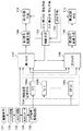
図1は、本実施の形態に係るビデオカメラ装置の構成を示すブロック図である。同図において、101はCCD等の撮像素子、102はCDS回路で、撮像素子101から出力された信号からクロック成分を除去し、連続した撮像信号を生成するものである。103はAGC回路で、入力信号の利得を自動的に制御するものである。104はA/Dコンバータで、AGC回路103からの信号をA/D変換するものである。105はカメラ信号処理回路で、A/Dコンバータ104からの信号を画像として処理するものである。106は特殊効果処理手段で、ワイプ処理部106a、フェード処理部106b、モザイク処理部106c等を有しており、これらの各処理部106a乃至106cによって、前段で処理された画像信号にワイプやフェードやモザイク等の特殊効果処理を施すものである。
【0027】
107は第1セレクタ、108は第2セレクタである。これら第1セレクタ107及び第2セレクタ108は、特殊効果処理手段106から出力された信号を任意に切り換えて、それぞれ後述する第1信号処理手段109及び第2信号処理手段110に入力するものである。109は第1信号処理手段、110は第2信号処理手段である。第1信号処理手段109は、第1セレクタ107で選択された信号を記録可能なように圧縮処理等を行ない、第1の画像信号として後述する第1記録手段111に入力するものである。また、第2信号処理手段110は、第2セレクタ108で選択された信号を記録可能なように圧縮処理等を行ない、第2の画像信号として後述する第2記録手段112に入力するものである。
【0028】
111は第1記録手段、112は第2記録手段である。第1の記録手段111は、第1の画像信号を記録媒体に記録するものである。第2の記録手段112は、第2の画像信号を記録媒体に記録するものである。113は制御手段で、第1、第2の画像信号それぞれに選択された特殊効果処理を施して記録するための動作を制御するものである。114は第1トリガ発生手段、115は第2トリガ発生手段である。これら第1、第2トリガ発生手段114,115は、任意のタイミングで、それぞれ第1、第2の画像信号の記録の実行/停止を指示するためのトリガ信号を発生するものである。116は選択手段で、本装置の使用者が第1、第2の画像信号に対して特殊効果処理を施すか否か及び施す特殊効果処理の種類を選択するためのものである。
【0029】
図1において、撮像素子101から読み出された信号は、CDS回路102においてクロック成分が除去されて連続した信号となり、AGC回路103によりCDS回路102から出力された信号の利得を制御し、A/Dコンバータ104によりデジタル信号に変換する。その後、カメラ信号処理部105により画像信号として処理される。
【0030】
そして、特殊効果処理手段106においてワイプやフェード、モザイク処理等の特殊効果処理が施される。この特殊効果処理手段106は、施す効果毎に内部で幾つかのブロックに分かれて処理を行うようになっており、複数種の特殊効果を並行して同時に処理することが可能であり、また、複数種の特殊効果処理手段を直列に並べることにより、幾つかの効果を組み合わせて施すことも可能である。
【0031】
第1セレクタ107及び第2セレクタ108には、特殊効果処理手段106から特殊効果処理を施された画像が入力されると共に、通常の画像がカメラ信号処理部105から入力され、それぞれのセレクタ107,108は、使用者の選択に応じて任意に入力画像を選択して第1、第2信号処理手段109,110に対して出力する。
【0032】
第1信号処理手段109及び第2信号処理手段110では、信号を記録するために必要な圧縮等の信号処理を行い、それぞれ第1の画像信号として第1記録手段111に、第2の画像信号として第2記録手段112に対して出力される。これら両信号処理手段111,112は、それぞれ処理方式の異なるものを用いることも可能であり、例えば、第1の画像信号は動画像、第2の画像信号は静止画像として処理すること等も考えられる。
【0033】
そして、第1記録手段111及び第2記録手段112は、それぞれ第1信号処理手段109及び第2信号処理手段110から出力された信号を後述する使用者が指定した任意のタイミングで記録する。これら両信号記録手段109,110は、同じ記録媒体を用いたものでも良いし、例えば、一方を磁気テープに、他方をメモリやディスクにといった異なった記録媒体を用いることも考えられる。
【0034】
使用者は選択手段116を用いて第1の画像信号及び第2の画像信号それぞれに対して特殊効果の種類や特殊効果の有無を選択する。このとき、選択手段116により選択された内容は図示していない表示手段を用いて表示確認できるようにすることも考えられる。そして、選択手段116により選択された内容を示す信号は制御手段113に送られる。制御手段113は、第1、第2セレクタ107,108を制御して、選択手段116により選択された内容に沿った画像をそれぞれ第1の画像信号、第2の画像信号として選び出す。そして、使用者は第1のトリガ発生手段114を操作することにより、第2の画像信号の記録の実行・中止を制御手段113に命令し、これに応じて制御手段113は、第1記録手段111と第2記録手段112を制御する。このとき、第1の画像信号が第1記録手段111に記録されている最中でも、第2の画像信号を第2記録手段112に記録することが可能であり、また、2つのトリガ発生手段114,115は1つで二通りのトリガを発生させる構成とすることにより、1つにまとめることも考えられる。
【0035】
次に、上記構成になる本実施の形態に係るビデオカメラ装置の動作を図2のフローチャートに基づき説明する。
【0036】
図2において、まず、ステップS201で使用者が選択手段116を通じて第1の画像信号及び第2の画像信号を適用する特殊効果の有無及び種類を選択する。次に、ステップS202で第1、第2セレクタ107,108を制御することにより、前記ステップS201において選択した内容に応じた特殊効果画像若しくは通常の画像が選択されて、後段へ出力される。
【0037】
前記ステップS202において第1セレクタ107側が選択された場合は、ステップS203で第1トリガ発生手段114から記録開始のトリガが発生したか否かを発生するまで判断する。そして、記録開始のトリガが発生すると、ステップS204で第1記録手段111を制御して、第1セレクタ107から第1信号処理手段109を通じて処理された第1の画像信号の第1記録手段111への記録を開始する。
【0038】
次に、ステップS205で第1トリガ発生手段114から記録終了のトリガが発生したか否かを発生するまで判断する。そして、記録終了のトリガが発生すると、ステップS206で第1記録手段111を制御して、その記録動作を停止した後、前記ステップS203へ戻って、再び記録開始のトリガの発生を待つ。
【0039】
一方、前記ステップS202において第2セレクタ108側が選択された場合は、ステップS207で第2トリガ発生手段115から記録開始のトリガが発生したか否かを発生するまで判断する。そして、記録開始のトリガが発生すると、ステップS208で第2記録手段112を制御して、第2セレクタ108から第2信号処理手段110を通じて処理された第2の画像信号の第2記録手段112への記録を開始する。
【0040】
次に、ステップS209で第2トリガ発生手段115から記録終了のトリガが発生したか否かを発生するまで判断する。そして、記録終了のトリガが発生すると、ステップS210で第2記録手段112を制御して、その記録動作を停止した後、前記ステップS203へ戻って、再び記録開始のトリガの発生を待つ。
【0041】
【発明の効果】
以上詳述したように本発明の撮像装置によれば、一方で任意の処理、例えば、特殊効果処理を施した撮影・記録を行っている途中でも、それに影響されることなのない通常の画像を、任意のタイミングで同時に記録したり、二つの画像信号各々に異なった任意の処理、例えば特殊効果を施して、任意のタイミングで同時に記録することが可能である。
【図面の簡単な説明】
【図1】本発明の一実施の形態に係るビデオカメラ装置の内部構成を示すブロック図である。
【図2】本発明の一実施の形態に係るビデオカメラ装置の動作の流れを示すフローチャートである。
【符号の説明】
101 撮像素子
102 CDS回路
103 AGC回路
104 A/Dコンバータ
105 カメラ信号処理回路
106 特殊効果処理手段
106a ワイプ処理部
106b フェード処理部
106c モザイク処理部
107 第1セレクタ
108 第2セレクタ
109 第1信号処理手段
110 第2信号処理手段
111 第1記録手段
112 第2信号処理手段
113 制御手段
114 第1トリガ発生手段
115 第2トリガ発生手段
116 選択手段[0001]
BACKGROUND OF THE INVENTION
The present invention relates to an imaging apparatus.
[0002]
[Prior art]
In recent years, there has been proposed a video camera apparatus capable of recording an image signal on a first recording medium such as a magnetic tape and at the same time recording it on a second recording medium such as a memory. For example, on the other hand, even during recording of a moving image, a still image is recorded on a recording medium different from the recording medium on which the moving image is recorded without stopping the recording operation. There are advantages such as being able to.
[0003]
[Problems to be solved by the invention]
However, in the conventional video camera apparatus capable of simultaneously recording images on the two recording media as described above, it is affected during shooting / recording using special effects such as fading and monochrome shooting. There is a problem that it is impossible to record a normal image which is not performed on the other side or to record each image with different special effect processing.
[0004]
The present invention has been made in view of the above-described problems of the prior art described above, and the object of the present invention is to perform shooting / recording on which arbitrary processing, for example, special effect processing is performed. A normal image that is not affected by the recording can be recorded simultaneously at any timing, or different processing can be performed on each of the two image signals, for example, special effect processing can be performed at any timing. An object of the present invention is to provide an imaging apparatus capable of recording simultaneously.
[0005]
[Means for Solving the Problems]
In order to achieve the above object, the imaging apparatus according to claim 1 performs a plurality of types of special effect processing on the imaging unit and the image signal output from the imaging unit, and each of the special effect processing is performed. Special effect processing means for outputting the first image signal and the second image signal, and first recording means for recording the first image signal output from the special effect processing means on the first recording medium; A second recording means for recording the second image signal output from the special effect processing means on a second recording medium different from the first recording medium; and Selection means for arbitrarily selecting the type of special effect processing to be performed on the image signal and the type of special effect processing to be performed on the second image signal from the plurality of types of special effect processing. It is characterized by.
[0006]
The imaging device according to claim 2 is the imaging device according to claim 1, wherein the second recording unit is configured to record the second image during recording of the first image signal by the first recording unit. A signal can be recorded .
[0007]
The image pickup apparatus according to claim 3 is the image pickup apparatus according to claim 1 or 2, wherein the second recording unit is configured to start recording during recording of the first image signal by the first recording unit. The second image signal is recorded in response to an instruction .
[0025]
DETAILED DESCRIPTION OF THE INVENTION
Hereinafter, an embodiment of the present invention will be described with reference to the drawings.
[0026]
FIG. 1 is a block diagram showing the configuration of the video camera apparatus according to the present embodiment. In the figure,
[0027]
107 is a first selector and 108 is a second selector. The
[0028]
[0029]
In FIG. 1, the signal read from the
[0030]
Then, special effect processing means 106 performs special effect processing such as wipe, fade, and mosaic processing. The special effect processing means 106 is configured to perform processing divided into several blocks for each effect to be applied, and can simultaneously process a plurality of types of special effects in parallel. It is possible to combine several effects by arranging a plurality of types of special effect processing means in series.
[0031]
The
[0032]
The first
[0033]
Then, the
[0034]
The user uses the
[0035]
Next, the operation of the video camera apparatus according to the present embodiment having the above configuration will be described with reference to the flowchart of FIG.
[0036]
In FIG. 2, first, in step S <b> 201, the user selects presence / absence and type of special effects to which the first image signal and the second image signal are applied through the
[0037]
If the
[0038]
Next, in step S205, determination is made until whether or not a recording end trigger is generated from the first trigger generating means 114. When a recording end trigger is generated, the
[0039]
On the other hand, if the
[0040]
Next, in step S209, it is determined until whether or not a recording end trigger is generated from the second trigger generating means 115. When a recording end trigger is generated, the
[0041]
【The invention's effect】
As described above in detail, according to the imaging apparatus of the present invention, a normal image that is not affected by an arbitrary process, for example, a shooting / recording process that has undergone a special effect process, can be obtained. It is possible to record simultaneously at an arbitrary timing, or simultaneously record at an arbitrary timing by applying different processes such as special effects to each of the two image signals.
[Brief description of the drawings]
FIG. 1 is a block diagram showing an internal configuration of a video camera apparatus according to an embodiment of the present invention.
FIG. 2 is a flowchart showing an operation flow of the video camera apparatus according to the embodiment of the present invention.
[Explanation of symbols]
DESCRIPTION OF
Claims (3)
前記撮像手段から出力された画像信号に対して複数種類の特殊効果処理を施して、それぞれ特殊効果処理が施された第1の画像信号と第2の画像信号を出力する特殊効果処理手段と、
前記特殊効果処理手段から出力された第1の画像信号を第1の記録媒体に記録する第1の記録手段と、
前記特殊効果処理手段から出力された第2の画像信号を前記第1の記録媒体とは異なる第2の記録媒体に記録する第2の記録手段と、
前記特殊効果処理手段により前記第1の画像信号に対して施す特殊効果処理の種類と前記第2の画像信号に対して施す特殊効果処理の種類とを、前記複数種類の特殊効果処理よりそれぞれ任意に選択する選択手段とを備えたことを特徴とする撮像装置。 Imaging means;
A special effect processing unit that performs a plurality of types of special effect processing on the image signal output from the imaging unit, and outputs a first image signal and a second image signal each subjected to the special effect processing;
First recording means for recording the first image signal output from the special effect processing means on a first recording medium;
Second recording means for recording the second image signal output from the special effect processing means on a second recording medium different from the first recording medium;
The type of special effect processing applied to the first image signal by the special effect processing means and the type of special effect processing applied to the second image signal can be arbitrarily selected from the plurality of types of special effect processing. An image pickup apparatus comprising: a selecting unit that selects the image pickup device .
Priority Applications (2)
| Application Number | Priority Date | Filing Date | Title |
|---|---|---|---|
| JP2000131325A JP4235342B2 (en) | 2000-04-28 | 2000-04-28 | Imaging device |
| US09/839,904 US6978086B2 (en) | 2000-04-28 | 2001-04-20 | Imaging apparatus |
Applications Claiming Priority (1)
| Application Number | Priority Date | Filing Date | Title |
|---|---|---|---|
| JP2000131325A JP4235342B2 (en) | 2000-04-28 | 2000-04-28 | Imaging device |
Publications (3)
| Publication Number | Publication Date |
|---|---|
| JP2001313857A JP2001313857A (en) | 2001-11-09 |
| JP2001313857A5 JP2001313857A5 (en) | 2006-09-21 |
| JP4235342B2 true JP4235342B2 (en) | 2009-03-11 |
Family
ID=18640238
Family Applications (1)
| Application Number | Title | Priority Date | Filing Date |
|---|---|---|---|
| JP2000131325A Expired - Fee Related JP4235342B2 (en) | 2000-04-28 | 2000-04-28 | Imaging device |
Country Status (2)
| Country | Link |
|---|---|
| US (1) | US6978086B2 (en) |
| JP (1) | JP4235342B2 (en) |
Families Citing this family (12)
| Publication number | Priority date | Publication date | Assignee | Title |
|---|---|---|---|---|
| DE19957540B4 (en) * | 1999-11-30 | 2005-07-07 | Infineon Technologies Ag | A method of fabricating a field effect transistor having an anti-punch-through implantation region |
| US7755669B2 (en) * | 2003-11-28 | 2010-07-13 | Canon Kabushiki Kaisha | Image capture apparatus and image capture method in which an image is processed by a plurality of image processing devices |
| JP4001135B2 (en) | 2004-08-18 | 2007-10-31 | ソニー株式会社 | Video signal processing device |
| JP2006186420A (en) * | 2004-12-24 | 2006-07-13 | Canon Inc | Imaging apparatus and its control method |
| US7495274B2 (en) | 2004-12-30 | 2009-02-24 | Ess Technology, Inc. | Method and apparatus for controlling charge transfer in CMOS sensors with a graded transfer-gate work-function |
| JP2010258757A (en) * | 2009-04-24 | 2010-11-11 | Olympus Imaging Corp | Moving image recording apparatus, imaging apparatus, moving image recording method, and moving image recording program |
| JP5300756B2 (en) * | 2010-02-05 | 2013-09-25 | キヤノン株式会社 | Imaging apparatus and image processing method |
| US20110295988A1 (en) * | 2010-05-28 | 2011-12-01 | Le Jouan Herve | Managing data on computer and telecommunications networks |
| JP5806512B2 (en) * | 2011-05-31 | 2015-11-10 | オリンパス株式会社 | Imaging apparatus, imaging method, and imaging program |
| US8827022B2 (en) | 2011-09-30 | 2014-09-09 | Mohammad Sadegh Jaberian | Chassis assembly for an electrical powered vehicle |
| JP6071610B2 (en) * | 2013-02-12 | 2017-02-01 | キヤノン株式会社 | Recording device |
| JP6082269B2 (en) * | 2013-02-21 | 2017-02-15 | キヤノン株式会社 | Recording apparatus and control method thereof |
Family Cites Families (4)
| Publication number | Priority date | Publication date | Assignee | Title |
|---|---|---|---|---|
| US5130860A (en) * | 1985-12-10 | 1992-07-14 | Canon Kabushiki Kaisha | Video signal recording apparatus |
| US6359649B1 (en) * | 1995-04-04 | 2002-03-19 | Canon Kabushiki Kaisa | Video camera integrated with still camera |
| JP4045651B2 (en) * | 1997-11-19 | 2008-02-13 | ソニー株式会社 | Information processing apparatus, information processing method, and program recording medium |
| JP2000050194A (en) * | 1998-07-27 | 2000-02-18 | Sony Corp | Image pickup device |
-
2000
- 2000-04-28 JP JP2000131325A patent/JP4235342B2/en not_active Expired - Fee Related
-
2001
- 2001-04-20 US US09/839,904 patent/US6978086B2/en active Active
Also Published As
| Publication number | Publication date |
|---|---|
| US20020008764A1 (en) | 2002-01-24 |
| JP2001313857A (en) | 2001-11-09 |
| US6978086B2 (en) | 2005-12-20 |
Similar Documents
| Publication | Publication Date | Title |
|---|---|---|
| JP4235342B2 (en) | Imaging device | |
| US8102434B2 (en) | Imaging apparatus, imaging method, and program | |
| JPH0795507A (en) | Electronic still camera | |
| JP2010226702A (en) | Imaging apparatus | |
| JP2003259301A (en) | System and method for capturing and embedding high- resolution still image data into video data stream | |
| KR100564186B1 (en) | Electronic camera | |
| JP4123352B2 (en) | Movie imaging device and movie playback device | |
| US20070081085A1 (en) | Image processing apparatus, image capturing apparatus, image processing method, and computer program | |
| JP4360781B2 (en) | Digital camera | |
| JP4429148B2 (en) | Image photographing and recording apparatus and method | |
| JP4313907B2 (en) | Imaging apparatus and control method thereof | |
| JP2004072374A (en) | Electronic still camera and image pickup method | |
| JP2006333216A (en) | Image reproducing apparatus, image reproducing method and control program | |
| JP3495582B2 (en) | Digital camera | |
| JP3915404B2 (en) | Imaging apparatus and white balance adjustment method thereof | |
| JP5600888B2 (en) | Image processing device | |
| JP4163297B2 (en) | Electronic still camera | |
| JP2008005350A (en) | Imaging apparatus and its control method | |
| JP3919534B2 (en) | Image reproducing apparatus and image reproducing method | |
| JPH0923371A (en) | Image pickup device | |
| JP2003199033A (en) | Image recording system, post-processing device for such system and cartridge associated therewith | |
| KR100708473B1 (en) | photographing apparatus for editing a screen in part and the screen in part editing method thereof | |
| JP4228479B2 (en) | Imaging apparatus and imaging method | |
| JP4147098B2 (en) | Image processing apparatus and image processing method | |
| JP3867737B2 (en) | Data processing apparatus and method |
Legal Events
| Date | Code | Title | Description |
|---|---|---|---|
| RD03 | Notification of appointment of power of attorney |
Free format text: JAPANESE INTERMEDIATE CODE: A7423 Effective date: 20060316 |
|
| A521 | Request for written amendment filed |
Free format text: JAPANESE INTERMEDIATE CODE: A523 Effective date: 20060727 |
|
| A621 | Written request for application examination |
Free format text: JAPANESE INTERMEDIATE CODE: A621 Effective date: 20060727 |
|
| RD05 | Notification of revocation of power of attorney |
Free format text: JAPANESE INTERMEDIATE CODE: A7425 Effective date: 20070626 |
|
| A977 | Report on retrieval |
Free format text: JAPANESE INTERMEDIATE CODE: A971007 Effective date: 20081119 |
|
| TRDD | Decision of grant or rejection written | ||
| A01 | Written decision to grant a patent or to grant a registration (utility model) |
Free format text: JAPANESE INTERMEDIATE CODE: A01 Effective date: 20081202 |
|
| A01 | Written decision to grant a patent or to grant a registration (utility model) |
Free format text: JAPANESE INTERMEDIATE CODE: A01 |
|
| A61 | First payment of annual fees (during grant procedure) |
Free format text: JAPANESE INTERMEDIATE CODE: A61 Effective date: 20081215 |
|
| FPAY | Renewal fee payment (event date is renewal date of database) |
Free format text: PAYMENT UNTIL: 20111219 Year of fee payment: 3 |
|
| R150 | Certificate of patent or registration of utility model |
Free format text: JAPANESE INTERMEDIATE CODE: R150 Ref document number: 4235342 Country of ref document: JP Free format text: JAPANESE INTERMEDIATE CODE: R150 |
|
| FPAY | Renewal fee payment (event date is renewal date of database) |
Free format text: PAYMENT UNTIL: 20121219 Year of fee payment: 4 |
|
| FPAY | Renewal fee payment (event date is renewal date of database) |
Free format text: PAYMENT UNTIL: 20131219 Year of fee payment: 5 |
|
| LAPS | Cancellation because of no payment of annual fees |