JP4230636B2 - Moving picture playback method and moving picture playback apparatus - Google Patents
Moving picture playback method and moving picture playback apparatus Download PDFInfo
- Publication number
- JP4230636B2 JP4230636B2 JP2000054598A JP2000054598A JP4230636B2 JP 4230636 B2 JP4230636 B2 JP 4230636B2 JP 2000054598 A JP2000054598 A JP 2000054598A JP 2000054598 A JP2000054598 A JP 2000054598A JP 4230636 B2 JP4230636 B2 JP 4230636B2
- Authority
- JP
- Japan
- Prior art keywords
- moving image
- delay
- decoding
- image signal
- reproduction
- Prior art date
- Legal status (The legal status is an assumption and is not a legal conclusion. Google has not performed a legal analysis and makes no representation as to the accuracy of the status listed.)
- Expired - Fee Related
Links
Images


Classifications
-
- H—ELECTRICITY
- H04—ELECTRIC COMMUNICATION TECHNIQUE
- H04N—PICTORIAL COMMUNICATION, e.g. TELEVISION
- H04N19/00—Methods or arrangements for coding, decoding, compressing or decompressing digital video signals
- H04N19/80—Details of filtering operations specially adapted for video compression, e.g. for pixel interpolation
-
- H—ELECTRICITY
- H04—ELECTRIC COMMUNICATION TECHNIQUE
- H04N—PICTORIAL COMMUNICATION, e.g. TELEVISION
- H04N21/00—Selective content distribution, e.g. interactive television or video on demand [VOD]
- H04N21/40—Client devices specifically adapted for the reception of or interaction with content, e.g. set-top-box [STB]; Operations thereof
- H04N21/43—Processing of content or additional data, e.g. demultiplexing additional data from a digital video stream; Elementary client operations, e.g. monitoring of home network or synchronising decoder's clock; Client middleware
- H04N21/4302—Content synchronisation processes, e.g. decoder synchronisation
- H04N21/4307—Synchronising the rendering of multiple content streams or additional data on devices, e.g. synchronisation of audio on a mobile phone with the video output on the TV screen
- H04N21/43072—Synchronising the rendering of multiple content streams or additional data on devices, e.g. synchronisation of audio on a mobile phone with the video output on the TV screen of multiple content streams on the same device
-
- H—ELECTRICITY
- H04—ELECTRIC COMMUNICATION TECHNIQUE
- H04N—PICTORIAL COMMUNICATION, e.g. TELEVISION
- H04N21/00—Selective content distribution, e.g. interactive television or video on demand [VOD]
- H04N21/40—Client devices specifically adapted for the reception of or interaction with content, e.g. set-top-box [STB]; Operations thereof
- H04N21/43—Processing of content or additional data, e.g. demultiplexing additional data from a digital video stream; Elementary client operations, e.g. monitoring of home network or synchronising decoder's clock; Client middleware
- H04N21/432—Content retrieval operation from a local storage medium, e.g. hard-disk
- H04N21/4325—Content retrieval operation from a local storage medium, e.g. hard-disk by playing back content from the storage medium
Description
【0001】
【発明の属する技術分野】
本発明は符号化された動画像信号を復号および再生するための動画像再生方法および動画再生装置に関し、特に滑らかな動画再生が行えるように改善された動画像再生方法および動画再生装置に関する。
【0002】
【従来の技術】
近年、コンピュータ技術の発達に伴い、デジタルビデオプレーヤ、セットトップボックス、デジタルTV、デジタルVCR、パーソナルコンピュータ等のマルチメディア対応の各種電子機器が開発されている。この種の電子機器では、MPEG2/MPEG4などの動画像高能率符号化方式で符号化された動画データを復号・再生するためのデコーダが設けられている。
【0003】
この種のデコーダにおいては、動画像信号を復号した後に、その復号画像に対してポストフィルタと称される画質改善のためのフィルタ処理が施されるのが通常である。MPEG2/MPEG4などに代表されるように、多くの符号化方式では画像をブロック単位で処理するため、その復号画像にはブロックノイズやエッジノイズといった劣化が生じる。ブロックノイズとは、本来の画像の絵柄にはないブロックパターン状の幾何学模様が見える歪みである。また、エッジノイズはエッジ付近に生じるリンギング状の歪み(モスキートノイズともいう)である。
【0004】
このような符号化方式固有のノイズを除去するのが、ポストフィルタである。ポストフィルタは復号画像信号を平滑化して、ブロック間の境界部における高域成分を取り除く等の処理を行う。このようなポストフィルタを動画像復号器後段に配したものとしては、たとえば特開昭64−55987号公報が知られている。この特開昭64−55987号公報には、ブロック単位処理を基本とする動画像復号器から出力された復号動画像信号に対して、動ブロック領域と静ブロック領域の判別を行い、その結果に応じて平滑化フィルタにおける平滑化の度合いを切り替え、処理を効率化する技術が開示されている。
【0005】
【発明が解決しようとする課題】
しかし、このようなポストフィルタによるフィルタ処理は比較的多くの演算量を必要とするため、フィルタ処理に時間がかかり、結果的に再生処理の遅れが引き起こされる場合がある。特に、マイクロプロセッサベースでソフトウェアデコードを行うシステムでは、動きの激しい場面においては復号処理そのものにプロセッサ資源が占有されてしまうので、それによってプロセッサ負荷が高くなり、再生処理の遅れが多々引き起こされることになる。再生処理の遅れは、音声と同期して動画像の復号・再生をソフトウェアによって行う場合に特に顕在化され、音声とのずれや、コマ落ちなどの問題が生じることになる。
【0006】
すなわち、動画像の再生処理に遅れが生じた場合には、通常、その遅れを解消するために、いくつかのフレームに関する復号処理を省くというフレームスキップが行われる。これにより、コマ落ちが発生し、ギクシャクとした再生画像となってしまう。
【0007】
本発明は上述の事情に鑑みてなされたものであり、フレームスキップの発生を極力排除できるようにし、滑らかな動画再生を行うことが可能な動画再生方法および動画再生装置を提供することを目的とする。
【0008】
【課題を解決するための手段】
上述の課題を解決するため、本発明は、符号化された動画像信号を復号および再生するための動画像再生方法であって、前記符号化された動画像信号を復号する復号ステップと、前記復号ステップによって復号された動画像信号に対してフィルタ処理を施すフィルタ処理ステップと、前記フィルタ処理ステップによってフィルタ処理された動画像信号を再生出力するステップと、前記動画像信号の再生状況に基づき、前記フィルタ処理ステップによるフィルタ処理を制御する再生制御ステップとを具備することを特徴とする。
【0009】
この動画再生方法においては、動画像信号の再生状況に基づいて、フィルタ処理の制御が行われ、現在の再生状況に最適なフィルタ処理を行うことができる。このように、画質調整のためのフィルタ処理の内容を最適化することにより、フレームスキップなどの処理を行わずとも、プロセッサの負荷状況に合わせて演算処理量を調整することができるので、滑らかな動画再生を実現することが可能となる。
【0010】
動画像信号の再生状況を表す指標としては、再生処理の遅れの度合いを用いることが好ましい。再生処理の遅れが検出された場合には、フィルタ処理の実行をスキップしたり、フィルタ処理の種類を処理量の少ない簡便なものに切り換えるという制御を行うことにより、再生処理の遅れを回復することが可能となる。これにより、フレームスキップによるコマ落ちの発生を防止できる。よって、プロセッサ負荷が増大する動きの激しいシーンなどにおいても滑らかな動画再生を実現することができる。なお、フィルタ処理をスキップしたり、フィルタ処理の種類を切り換えることにより、画質改善効果については低下するものの、一般に、それによって視覚的に認識される画質低下の度合いは、コマ落ちの発生に比べ非常に小さい。
【0011】
また、再生処理の遅れ量を、状態変数などを用いて管理することにより、遅れの度合いに応じてフィルタ処理の種類を処理量の少ないものに段階的に切り換えていき、最終的にフィルタ処理の実行をスキップするという多段階制御を利用することにより、画質改善効果の低下を最小限に抑えることができる。
【0012】
また、上述のフィルタ処理の制御とフレームスキップ処理とを組み合わせて、再生処理の遅れの度合いがある一定の範囲内のうちはフィルタ処理の制御のみを行い、遅れ量が所定の値に達した場合に初めて復号ステップの実行を所定フレーム数分スキップさせるように制御することにより、滑らかな動画再生と、破綻のない正常な再生処理を両立することが可能となる。
【0013】
【発明の実施の形態】
以下、図面を参照して本発明の実施形態を説明する。
図1には、本発明の一実施形態に係る動画再生装置の一例として、パーソナルコンピュータを用いた場合の構成が示されている。このパーソナルコンピュータはノートブックタイプの携帯型のコンピュータシステムであり、MPEG2/MPEG4等によって圧縮符号化されたオーディオ・ビデオストリームをソフトウェアによって復号・再生することができる。
【0014】
図1のコンピュータシステムにおいては、図示のように、CPU11、ホスト−PCIブリッジ12、主メモリ13、表示コントローラ14、サウンドコントローラ15、通信インターフェース16、I/Oコントーラ17、PCI−ISAブリッジ18、カメラ20、ハードディスクドライブ(HDD)21、DVDドライブ22などが設けられている。
【0015】
CPU11は本システム全体を制御するためのものであり、主メモリ13にロードされたオペレーティングシステムや他の各種プログラムを実行する。本実施形態においては、オーディオ・ビデオストリームの復号・再生のためのプログラムとして、動画再生ソフトウェア100が用いられる。この動画再生ソフトウェア100は、MPEG2、MPEG4、AVI、DVIなどの各種圧縮形式のAV(オーディオ・ビデオ)データに対応しており、AVデータの符号化ファイルを読み込み、それを復号・再生することができる。
【0016】
ホスト−PCIブリッジ12はCPUバス1とPCIバス2を接続するバスブリッジであり、ここには主メモリ13を制御するためのメモリコントロールロジックも内蔵されている。表示コントローラ14は本コンピュータシステムのディスプレイモニタとして使用されるLCDや外部CRTディスプレイを制御する。AVデータの再生時には、動画再生ソフトウェア100によって得られた復号画像信号が表示コントローラ14を通じてディスプレイモニタに表示されることになる。
【0017】
サウンドコントローラ15は音源として用いられるものであり、各種オーディオデータの入出力を行う。AVデータの再生時には、動画再生ソフトウェア100によって得られた復号音声信号がサウンドコントローラ15を通じてスピーカから再生、あるいはラインアウト端子から外部オーディオ機器に出力される。
【0018】
通信インターフェース16は、たとえばUSBやIEEE1394などのシリアルインターフェース規格で外部または内蔵のカメラ20と通信するためのものであり、カメラ20からビデオデータを取り込むことができる。カメラ20によって撮影された動画像信号は、そのまま再生表示したり、あるいはMPEG2、MPEG4、AVI、DVIなどの各種圧縮形式に変換した後にI/Oコントローラ17を介してHDD21、DVDドライブ22、メモリカード23などの各種記録メディアに記録することができる。
【0019】
PCI−ISAブリッジ18はPCIバス2とISAバス3との間を接続するバスブリッジであり、ここにはリアルタイムクロック(RTC)181などの各種システムデバイスが内蔵されている。リアルタイムクロック(RTC)181は時計モジュールであり、本実施形態では、このリアルタイムクロック(RTC)181から取得した時刻を用いてAVデータの再生処理の遅れを管理している。
【0020】
(動画再生ソフト)
ここで、図2および図3を参照して、動画再生ソフト100の基本機能について説明する。
【0021】
前述したように、動画再生ソフトウェア100は、HDD21、DVDドライブ22、またはメモリカード23などの蓄積メディアに記録されているAVデータの符号化ファイルを読み込み、それを復号・再生することができる。図2には、HDD21に記録されているAV符号化ファイル210を復号・再生する場合の様子が示されている。
【0022】
AV符号化ファイル210には、動画像信号とオーディオ信号をそれぞれデジタル圧縮符号化した後にそれらの符号化ビットストリームを多重化することによって生成されたものである。動画再生ソフト100は、HDD21からAV符号化ファイル210を読み取り、動画像信号とオーディオ信号とに分離した後にそれぞれを伸張するための復号処理を行い、そして動画像をディスプレイモニタに表示すると共に、オーディオ信号をスピーカなどから再生する。
【0023】
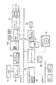
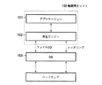
動画再生ソフトウェア100は、図3に示されているように、アプリケーションプログラム101と再生エンジン102とから構成されている。アプリケーションプログラム101は動画再生処理のためのユーザインターフェースと再生エンジン102を制御するためのインターフェースとを有しており、ユーザから指定されたAV符号化ファイル210の再生に必要な動作を、再生エンジン102に対して指示する。再生エンジン102は、オペレーティングシステム(OS)103上に実装されたマルチメディア処理用のプラットホームであり、ファィル入出力処理や動画/音声再生のためのレンダリング処理をはじめとする、動画・音声再生のために必要な処理を行う種々のプログラムモジュール(フィルタ)群から構成されている。これらモジュールはアプリケーションプログラム101からの指示により任意に組み合わせて用いることができる。
【0024】
(再生エンジン)
次に、再生エンジン102の機能構成を説明する。図4は、AV符号化ファイルの再生時におけるモジュール構成を示している。
【0025】
AV符号化ファイルに含まれる動画・オーディオの再生は、マネージャ301、ファイルリーダ302、デマルチプレクサ(DMUX)303、ビデオデコーダ304、ビデオレンダラ305、オーディオデコーダ306、オーディオレンダラ307を図示のようにリンクさせることによって実現される。
【0026】
まず、再生対象の符号化ファイルがファイルリーダ302によってリードされ、そこに含まれる符号化ビットストリームがデマルチプレクサ(DMUX)303に送られ、そこで動画データとオーディオデータとに分離される。
【0027】
動画データについては、デマルチプレクサ(DMUX)303内でフレーム単位に分離され、1フレームずつビデオデコーダ304に送られる。ビデオデコーダ304は動画データを復号・再生するためのモジュールであり、ここには画像伸張処理機能および画質改善のためのフィルタ処理機能などが含まれている。ビデオデコーダ304によって得られた復号画像はビデオレンダラ305を介して表示コントローラ14に送られ、モニタ上に画面表示される。一方、オーディオデータはオーディオデコーダ306によって復号された後に、オーディオレンダラ307を介してサウンドコントローラ15に送られ、スピーカなどから再生出力される。
【0028】
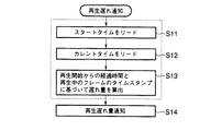
マネージャ301は動画の再生状況を管理するためのものであり、再生処理に遅れが生じたときにそれを最下流のビデオレンダラ305に通知する(再生遅れ通知)。符号化された動画データには、図5に示すようにフレーム毎にタイムスタンプTSが埋め込まれているため、マネージャ301は、再生開始からの経過時間と再生中のフレームのタイムスタンプとを比較することにより、再生処理速度を監視することができる。マネージャ301からの再生処理の遅れ通知は、ビデオレンダラ305から順に上流側のモジュールへと伝達される。つまり、ビデオデコーダ304による復号・再生処理の状況が、ビデオレンダラ305を介してビデオデコーダ304にフィードバックされることになる。
【0029】
(再生遅れ通知)
図6には、再生遅れ通知を発行するために必要なマネージャ301の処理手順が示されている。マネージャ301は、動画再生の開始時にRTC181からそのときの時刻(スタートタイム)を取得する(ステップS11)。そして、定期的にRTC181から現在時刻(カレントタイム)を取得し(ステップS12)、再生開始からの経過時間と再生中のフレームのタイムスタンプとを比較することによって、遅れ量を算出する(ステップS13)。再生中フレームのタイムスタンプはビデオレンダラ305から取得してもよいが、再生中フレームの何フレームか後のフレームのタイムスタンプをデマルチプレクサ(DMUX)303から取得し、それを再生中フレームのタイムスタンプの値に換算してもよい。AVIフォーマットの符号化データの場合には、たとえばMPEG2/MPEG4等で圧縮符号化されたストリームに対してタイムスタンプを含むヘッダが挿入されるので、MPEG2/MPEG4固有のタイムスタンプではなく、AVIフォーマットのタイムスタンプを利用することもできる。
【0030】
算出された遅れ量は、再生速度などの値に換算されてビデオレンダラ305に通知される(ステップS14)。この場合、再生速度は100%を正常速度として表し、遅れ量の度合いに応じて再生速度を示す%の値は低下する。
【0031】
(ビデオデコーダ)
次に、図7を参照して、本実施形態の特徴とするビデオデコーダ304の構成を説明する。
ビデオデコーダ304は、前述したように再生エンジン102内の1モジュールとして動作するものであり、図示のように、画像伸張部501、画質改善部502、画像出力部503、遅れ検出部504、状態変数505、およびコントロール部506から構成されている。符号化された動画像信号の復号・再生を行うための復号処理部は、画像伸張部501、画質改善部502、および画像出力部503から構成されている。
【0032】
画像伸張部501は圧縮動画像を復号して伸張するためのものであり、MPEG2/MPEG4で圧縮された動画像信号については、可変長復号処理、逆量子化、逆DCT、動き補償予測、差分復号画像への予測画像の加算などの処理を行う。画像伸張部501によって1フレーム分の復号画像が得られると、それが画質改善部502に送られる。
【0033】
画質改善部502は復号画像の画質改善のためにブロックノイズ削減等のための平滑化フィルタ処理を行うためのものポストフィルタであり、フィルタの種類(IIRフィルタ、FIRフィルタ)の切り換え、およびフィルタパラメータの設定により、処理速度やフィルタ強度の異なる様々なフィルタ処理を復号画像信号に対して施すことができる。なお、ここで平滑化フィルタ処理は画質調整のための演算処理の一例であり、それ以外の様々な画質調整処理を含めて以下ではフィルタ処理と称することにする。
【0034】
この画質改善部502によるフィルタ処理の内容はコントロール部506によって制御される。
【0035】
画像出力部503は、画質改善部502によって処理された復号画像を前述のビデオレンダラ305に出力する。遅れ検出部504はビデオレンダラ305を通じてマネージャ301から伝達される遅れ通知に従って動画像信号の再生処理の遅れを検出するためのものであり、状態変数505を用いて再生処理の遅れの度合いを現在の再生状況として管理する。
【0036】
コントロール部506は、画像伸張部501、画質改善部502、および画像出力部503から構成される復号処理部の動作を制御するためのものであり、画質改善部502によるフィルタ処理の最適化制御を行う。具体的には、コントロール部506は、画像伸張部501による復号処理のスキップ(フレームスキップ)を極力排除した状態で、再生処理の遅れを回復させるための制御を行うために、状態変数505の値に応じてフィルタ処理の実行をスキップしたり、あるいはフィルタ処理の種類を処理量の少ない簡便なものに切り換えるなどの遅れ回復制御を行う。以下、遅れ回復制御処理の具体的な手順について説明する。
【0037】
(遅れ回復制御#1)
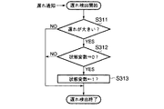
まず、図8および図9を参照して、遅れ回復制御処理の第1の例について説明する。本例では、2値の状態変数505(“0”または“1”)によって遅れ回復が必要な遅れであるか否かを管理し、遅れ回復が必要な遅れである場合には(状態変数=“1”)、画質改善のためのフィルタ処理をスキップさせるという処理が行われる。
【0038】
図8は遅れ検出部504による遅れ検出処理を示したフローチャートである。図8に示されているように、遅れ検出部504は、ビデオレンダラ305を通じてマネージャ301からの再生遅れ通知を受けると、まず、その再生遅れ通知によって遅れ量として指定される再生速度(%)の値に基づき、再生処理の遅れがあらかじめ決められた所定量よりも大きいか否かを判定する(ステップS311)。再生処理の遅れが所定量以下であれば(ステップS311のNO)、なにもせずに処理を終了する。一方、再生処理の遅れが所定量よりも大きい場合には(ステップS311のYES)、状態変数505の現在の値をチェックする(ステップS312)。
【0039】
状態変数=“0”であれば(ステップS312のYES)、遅れ検出部504は、遅れ回復処理が必要であることをコントロール部506に通知するために、状態変数の値を“1”に変更し(ステップS313)、状態変数がすでに“1”であれば(ステップS312のNO)、なにもせずに処理を終了する。
【0040】
図9はコントロール部506によって各フレーム毎に行われる復号制御処理の手順を示すフローチャートである。まず、画像伸張部501によって該当するフレームの復号処理が実行される(ステップS351)。1フレーム分の復号処理が終了した時点で、コントロール部506は、状態変数505をチェックする(ステップS352)。状態変数が“0”であれば(ステップS352のNO)、コントロール部506は、通常通り、復号された1フレーム画像を画質改善部502に渡し、画質改善のための平滑化フィルタ処理を実行させる(ステップS353)。そして、フィルタ処理を受けた画像信号が画像出力部503から出力される(ステップS354)。一方、状態変数が“1”であれば(ステップS352のYES)、コントロール部506は、画質改善部502による画質改善のためのフィルタ処理をスキップさせ、フィルタ処理を実行せずに、復号画像をそのまま画像出力部503から出力させる(ステップS354)。
【0041】
このように、CPU負荷が高く、再生処理速度に遅れが生じた場合でも、復号処理自体は間引くことなく、フィルタ処理の最適化制御を行うことにより、こま落ちのない滑らかな動画再生が可能となる。
【0042】
(遅れ回復制御#2)
次に、図10および図11を参照して、遅れ回復制御処理の第2の例について説明する。本例では、“0”,“1”,“2”,“3”の4値の状態変数505によって再生処理の遅れ量の度合いを管理し、それに応じて段階的にフィルタ処理の内容を変更するという処理が行われる。
【0043】
図10は遅れ検出部504による遅れ検出処理を示したフローチャートである。図10に示されているように、遅れ検出部504は、ビデオレンダラ305を通じてマネージャ301からの再生遅れ通知を受けると、まず、その再生遅れ通知によって遅れ量として指定される再生速度(%)の値に基づき、再生処理の遅れがあらかじめ決められた所定量よりも大きいか否かを判定する(ステップS411)。再生処理の遅れが所定量以下であれば(ステップS411のNO)、なにもせずに処理を終了する。一方、再生処理の遅れが所定量よりも大きい場合には(ステップS411のYES)、状態変数505の現在の値をチェックする(ステップS412)。
【0044】
状態変数が最高値“3”よりも小さい場合には(ステップS412のYES)、遅れ検出部504は、遅れ量の度合いを示す状態変数の値を+1増加させ(ステップS413)、状態変数がすでに最高値“3”であれば(ステップS412のNO)、なにもせずに処理を終了する。
【0045】
図11はコントロール部506によって各フレーム毎に行われる復号制御処理の手順を示すフローチャートである。まず、画像伸張部501によって該当するフレームの復号処理が実行される(ステップS451)。1フレーム分の復号処理が終了した時点で、コントロール部506は、状態変数505をチェックし(ステップS452)、その状態変数の値に応じてフィルタの内容を切り換える。本例では、演算処理量の異なる3つのフィルタ処理A,B,Cがあらかじめ用意されている。フィルタ処理Aはもっとも画質改善に効果のあるフィルタ処理であるが、演算処理に時間を要する。次に、画質改善効果が期待できるのがフィルタ処理Bで、最後がフィルタ処理Cである。CPU11の負荷はフィルタ処理A,B,Cの順で少なくなる。
【0046】
状態変数が“0”であれば、コントロール部506は、復号された1フレーム画像を画質改善部502に渡し、フィルタ処理Aを実行させる(ステップS353)。そして、フィルタ処理を受けた画像信号が画像出力部503から出力される(ステップS456)。同様に、状態変数が“1”であればフィルタ処理Bを、状態変数が“2”であればフィルタ処理Cを実行させる(ステップS454,S455)。一方、状態変数が最高値“3”であれば、コントロール部506は、画質改善部502による画質改善のためのフィルタ処理をスキップさせ、フィルタ処理を実行せずに、復号画像をそのまま画像出力部503から出力させる(ステップS456)。
【0047】
このように、遅れの度合いに応じて徐々にフィルタ処理の内容を粗くするという制御を行うことにより、急激な画質変化をもたらすことなく、こま落ちのない滑らかな動画再生を行うことが可能となる。
【0048】
(遅れ回復制御#3)
次に、図12および図13を参照して、遅れ回復制御処理の第3の例について説明する。本例は、“0”,“1”,“2”の3値の状態変数505によって再生処理の遅れ量の度合いを管理し、フィルタ処理の実行の有無の切り替えと、フレームスキップとを組み合わせて行う場合の例である。
【0049】
図12は遅れ検出部504による遅れ検出処理を示したフローチャートである。図12に示されているように、遅れ検出部504は、ビデオレンダラ305を通じてマネージャ301からの再生遅れ通知を受けると、まず、その再生遅れ通知によって遅れ量として指定される再生速度(%)の値に基づき、再生処理の遅れがあらかじめ決められた所定量よりも大きいか否かを判定する(ステップS511)。再生処理の遅れが所定量以下であれば(ステップS511のNO)、なにもせずに処理を終了する。一方、再生処理の遅れが所定量よりも大きい場合には(ステップS511のYES)、状態変数505の現在の値をチェックする(ステップS512)。
【0050】
状態変数が最高値“2”よりも小さい場合には(ステップS512のYES)、遅れ検出部504は、遅れ量の度合いを示す状態変数の値を+1増加させ(ステップS513)、状態変数がすでに最高値“2”であれば(ステップS512のNO)、なにもせずに処理を終了する。
【0051】
図13はコントロール部506によって各フレーム毎に行われる復号制御処理の手順を示すフローチャートである。コントロール部506は、まず、画像伸張部501によるフレームの復号処理の実行に先立ち、状態変数505をチェックする(ステップS551)。状態変数505が最高値“2”であれば(ステップS511のYES)、復号処理、フィルタ処理、画像出力処理をすべてスキップし、これによりフレームスキップを行う。
【0052】
一方、状態変数505が“1”以下であれば(ステップS511のNO)、コントロール部506は、画像伸張部501に該当するフレームの復号処理を実行させた後に(ステップS552)、状態変数505が“0”であるか“1”であるかを判断する(ステップS553)。状態変数が“0”であれば(ステップS553のNO)、コントロール部506は、通常通り、復号された1フレーム画像を画質改善部502に渡し、画質改善のための平滑化フィルタ処理を実行させる(ステップS554)。そして、フィルタ処理を受けた画像信号が画像出力部503から出力される(ステップS555)。状態変数が“1”であれば(ステップS553のYES)、コントロール部506は、画質改善部502による画質改善のためのフィルタ処理をスキップさせ、フィルタ処理を実行せずに、復号画像をそのまま画像出力部503から出力させる(ステップS555)。
【0053】
このように、再生遅れ量がある一定の範囲内にある場合にはフィルタ処理のスキップのみを行い、ある一定の範囲以上になったときに初めてフレームスキップを実行するという制御を行うことにより、滑らかな動画再生と、破綻のない再生処理との両立を図ることが可能となる。なお、この制御は、前述の第2の例においても適用することができる。この場合、再生遅れ量がある一定の範囲内にある場合にはフィルタ処理の段階的な制御が行われ、ある一定の範囲以上になったときにフレームスキップが実行されることになる。
【0054】
以上のように、本実施形態においては、CPU負荷が大きくなり再生処理に遅れが生じた場合にはフィルタ処理の内容を制御することによってCPU負荷を低減するという制御を行っているので、CPUの負荷状況に合わせて画質調整処理の内容を最適化できるようになり、ソフトウェアデコードによって音声と同期して動画の復号・再生を行う場合においても、フレームスキップが発生する頻度を極力抑えることが可能となる。
【0055】
また、本実施形態では、再生中のフレームのタイムスタンプと再生開始からの経過時間との比較によって再生遅れ通知を生成する場合を例示したが、たとえばレート制御されたバッファの占有量などを用いて再生遅れの度合いを検出し、それに応じてフィルタ処理の内容を制御することも可能である。
【0056】
また、本実施形態では、状態変数を低下させる処理については特に説明しなかったが、状態変数の値は再生遅れが少なくなったときなどに低下させればよいことはもちろんである。
【0057】
さらに、本実施形態のソフトウェアデコードの方法は、その手順を含むコンピュータプログラムをコンピュータ読み取り可能な記録媒体を通じて通常のコンピュータに導入するだけで、容易に実現することができる。また、コンピュータのみならず、ゲーム機や、デジタルTV、セットトップボックスなどにも適用することができる。
【0058】
【発明の効果】
以上説明したように、本発明によれば、復号画像の画質改善ためのフィルタ処理を制御することにより、フレームスキップの発生を極力排除できるようになり、滑らかな動画再生を行うことが可能となる。
【図面の簡単な説明】
【図1】本発明の一実施形態に係るコンピュータシステムの構成を示すブロック図。
【図2】同実施形態で用いられる動画再生ソフトの基本機能を説明するための図。
【図3】同実施形態で用いられる動画再生ソフトの構造を示す図。
【図4】同実施形態で用いられる動画再生ソフトの再生エンジン部の機能構成を示す図。
【図5】同実施形態における動画像信号のストリーム構造の一例を示す図。
【図6】同実施形態で用いられる再生遅れ通知処理の手順を示すフローチャート。
【図7】同実施形態の再生エンジン部に設けられるビデオデコーダの機能構成を示す図。
【図8】同実施形態で用いられる遅れ検出処理の第1の例を示すフローチャート。
【図9】同実施形態で用いられる復号制御処理の第1の例を示すフローチャート。
【図10】同実施形態で用いられる遅れ検出処理の第2の例を示すフローチャート。
【図11】同実施形態で用いられる復号制御処理の第2の例を示すフローチャート。
【図12】同実施形態で用いられる遅れ検出処理の第3の例を示すフローチャート。
【図13】同実施形態で用いられる復号制御処理の第3の例を示すフローチャート。
【符号の説明】
11…CPU
100…動画再生ソフト
101…動画再生用アプリケーションプログラム
102…再生エンジン
301…マネージャ
302…ファイルリーダ
303…デマルチプレクサ(DMUX)
304…ビデオデコーダ
305…ビデオレンダラ
306…オーディオデコーダ
307…オーディオレンダラ
501…画像伸張部
502…画質改善部
503…画像出力部
504…遅れ検出部
505…状態変数
506…コントロール部[0001]
BACKGROUND OF THE INVENTION
The present invention relates to a moving image reproducing method and a moving image reproducing device for decoding and reproducing an encoded moving image signal, and more particularly to a moving image reproducing method and a moving image reproducing device improved so that smooth moving image reproduction can be performed.
[0002]
[Prior art]
In recent years, with the development of computer technology, various electronic devices for multimedia such as digital video players, set-top boxes, digital TVs, digital VCRs, personal computers and the like have been developed. In this type of electronic device, a decoder is provided for decoding and reproducing moving image data encoded by a moving image high-efficiency encoding method such as MPEG2 / MPEG4.
[0003]
In this type of decoder, after decoding a moving image signal, a filter process for improving image quality called a post filter is usually performed on the decoded image. As represented by MPEG2 / MPEG4 and the like, in many encoding methods, an image is processed in units of blocks, so that the decoded image is deteriorated such as block noise and edge noise. Block noise is a distortion in which a block pattern-like geometric pattern that does not exist in the original image pattern can be seen. Edge noise is ringing-like distortion (also referred to as mosquito noise) generated near the edge.
[0004]
It is the post filter that removes such noise inherent to the encoding system. The post filter performs a process such as smoothing the decoded image signal and removing a high frequency component at a boundary between blocks. For example, Japanese Patent Application Laid-Open No. 64-55987 is known as such a post filter disposed in the latter stage of the moving picture decoder. In this Japanese Patent Application Laid-Open No. 64-55987, a moving block area and a static block area are discriminated from a decoded moving image signal output from a moving image decoder based on block unit processing, and the result is shown in FIG. Accordingly, a technique for switching the degree of smoothing in the smoothing filter to improve the processing efficiency is disclosed.
[0005]
[Problems to be solved by the invention]
However, since the filtering process using such a post filter requires a relatively large amount of calculation, the filtering process takes time, and as a result, a reproduction process may be delayed. In particular, in a microprocessor-based software decoding system, processor resources are occupied by the decoding process itself in a scene where motion is intense, which increases the processor load and causes many delays in the reproduction process. Become. The delay in reproduction processing becomes particularly apparent when software decodes and reproduces a moving image in synchronization with audio, and causes problems such as deviation from audio and frame dropping.
[0006]
That is, when a delay occurs in the moving image playback process, frame skip is usually performed in order to eliminate the delay in order to eliminate the delay. As a result, frame dropping occurs, resulting in a jerky reproduced image.
[0007]
The present invention has been made in view of the above circumstances, and an object thereof is to provide a moving image reproducing method and a moving image reproducing apparatus capable of eliminating the occurrence of frame skip as much as possible and performing smooth moving image reproduction. To do.
[0008]
[Means for Solving the Problems]
In order to solve the above-described problem, the present invention provides a moving image reproduction method for decoding and reproducing an encoded moving image signal, the decoding step for decoding the encoded moving image signal, Based on a filtering process step of performing a filtering process on the moving image signal decoded by the decoding step, a step of reproducing and outputting the moving image signal filtered by the filtering step, and a reproduction state of the moving image signal, And a regeneration control step for controlling the filter processing by the filter processing step.
[0009]
In this moving image reproduction method, the filter processing is controlled based on the reproduction status of the moving image signal, and the optimum filter processing can be performed for the current reproduction status. As described above, by optimizing the contents of the filter processing for image quality adjustment, the calculation processing amount can be adjusted according to the load state of the processor without performing processing such as frame skipping. It is possible to realize video playback.
[0010]
It is preferable to use the degree of delay in the reproduction process as an index representing the reproduction status of the moving image signal. When a delay in the playback process is detected, the delay in the playback process can be recovered by performing control such as skipping the execution of the filter process or switching the filter process type to a simple process with a small amount of processing. Is possible. As a result, frame dropping due to frame skipping can be prevented. Therefore, smooth moving image reproduction can be realized even in a scene where the processor load increases and the movement is intense. Note that skipping filter processing or switching the type of filter processing reduces the image quality improvement effect, but generally the degree of image quality degradation visually recognized by this is much less than the occurrence of frame dropping. Small.
[0011]
In addition, by managing the amount of delay in playback processing using state variables, etc., the type of filter processing is switched step by step to one with less processing amount according to the degree of delay, and finally the filter processing By using multi-stage control of skipping execution, it is possible to minimize the deterioration of the image quality improvement effect.
[0012]
In addition, when the above-described filter processing control and frame skip processing are combined, only the filter processing is controlled within a certain range where the degree of delay in the reproduction processing is reached, and the delay amount reaches a predetermined value By first controlling the execution of the decoding step to skip a predetermined number of frames, it is possible to achieve both smooth moving image reproduction and normal reproduction processing without failure.
[0013]
DETAILED DESCRIPTION OF THE INVENTION
Hereinafter, embodiments of the present invention will be described with reference to the drawings.
FIG. 1 shows a configuration in which a personal computer is used as an example of a moving image playback apparatus according to an embodiment of the present invention. This personal computer is a notebook type portable computer system, which can decode and reproduce audio / video streams compressed and encoded by MPEG2 / MPEG4 or the like by software.
[0014]
In the computer system of FIG. 1, as shown in the figure, a
[0015]
The
[0016]
The host-
[0017]
The
[0018]
The
[0019]
The PCI-
[0020]
(Video playback software)
Here, with reference to FIG. 2 and FIG. 3, the basic function of the moving
[0021]
As described above, the moving
[0022]
The AV encoded
[0023]
As shown in FIG. 3, the moving
[0024]
(Playback engine)
Next, the functional configuration of the
[0025]
For reproduction of video / audio included in an AV encoded file, the
[0026]
First, an encoded file to be reproduced is read by the
[0027]
The moving image data is separated into frames in a demultiplexer (DMUX) 303 and sent to the
[0028]
The
[0029]
(Playback delay notification)
FIG. 6 shows a processing procedure of the
[0030]
The calculated delay amount is converted into a value such as a playback speed and notified to the video renderer 305 (step S14). In this case, the playback speed is expressed as 100% as a normal speed, and the value of% indicating the playback speed decreases according to the degree of delay.
[0031]
(Video decoder)
Next, the configuration of the
As described above, the
[0032]
The
[0033]
The image
[0034]
The contents of the filter processing by the image
[0035]
The
[0036]
The
[0037]
(Delayed recovery control # 1)
First, a first example of the delay recovery control process will be described with reference to FIGS. 8 and 9. In this example, the binary state variable 505 (“0” or “1”) manages whether or not the delay needs to be delayed, and if the delay needs to be recovered (state variable = “1”), a process of skipping filter processing for improving image quality is performed.
[0038]
FIG. 8 is a flowchart showing a delay detection process by the
[0039]
If the state variable = “0” (YES in step S312), the
[0040]
FIG. 9 is a flowchart showing a decoding control process performed by the
[0041]
As described above, even when the CPU load is high and the playback processing speed is delayed, the decoding process itself is not thinned out, and the filtering process optimization control is performed, so that smooth video playback without dropping can be performed. Become.
[0042]
(Delayed recovery control # 2)
Next, a second example of the delay recovery control process will be described with reference to FIGS. 10 and 11. In this example, the degree of delay in the reproduction process is managed by the four-
[0043]
FIG. 10 is a flowchart showing a delay detection process by the
[0044]
When the state variable is smaller than the maximum value “3” (YES in step S412), the
[0045]
FIG. 11 is a flowchart illustrating a procedure of decoding control processing performed for each frame by the
[0046]
If the state variable is “0”, the
[0047]
In this way, by controlling so as to gradually roughen the content of the filter processing in accordance with the degree of delay, it becomes possible to perform smooth video reproduction without dropping a sharpness without causing a sudden change in image quality. .
[0048]
(Delayed recovery control # 3)
Next, a third example of the delay recovery control process will be described with reference to FIGS. In this example, the degree of delay in the reproduction process is managed by a
[0049]
FIG. 12 is a flowchart showing a delay detection process by the
[0050]
When the state variable is smaller than the maximum value “2” (YES in step S512), the
[0051]
FIG. 13 is a flowchart showing a decoding control process performed by the
[0052]
On the other hand, if the
[0053]
As described above, when the playback delay amount is within a certain range, only the filtering process is skipped, and the frame skip is performed only when the playback delay amount exceeds the certain range, thereby performing smoothness. It is possible to achieve both the reproduction of a moving image and the reproduction processing without failure. This control can also be applied to the second example described above. In this case, when the reproduction delay amount is within a certain range, stepwise control of the filter processing is performed, and frame skip is executed when it exceeds a certain range.
[0054]
As described above, in the present embodiment, when the CPU load increases and a delay occurs in the reproduction process, control is performed to reduce the CPU load by controlling the content of the filter process. It is now possible to optimize the contents of image quality adjustment processing according to the load situation, and it is possible to suppress the frequency of frame skips as much as possible even when decoding and playing video in synchronization with audio by software decoding Become.
[0055]
Further, in the present embodiment, the case where the reproduction delay notification is generated by comparing the time stamp of the frame being reproduced and the elapsed time from the reproduction start is illustrated, but for example, the rate-controlled buffer occupation amount is used. It is also possible to detect the degree of reproduction delay and control the contents of the filter processing accordingly.
[0056]
In the present embodiment, the process for reducing the state variable has not been described in particular. However, it is needless to say that the value of the state variable may be reduced when the reproduction delay is reduced.
[0057]
Furthermore, the software decoding method of the present embodiment can be easily realized simply by introducing a computer program including the procedure into a normal computer through a computer-readable recording medium. Further, it can be applied not only to a computer but also to a game machine, a digital TV, a set top box, and the like.
[0058]
【The invention's effect】
As described above, according to the present invention, by controlling the filter processing for improving the image quality of the decoded image, the occurrence of frame skip can be eliminated as much as possible, and smooth moving image reproduction can be performed. .
[Brief description of the drawings]
FIG. 1 is a block diagram showing a configuration of a computer system according to an embodiment of the present invention.
FIG. 2 is a view for explaining basic functions of moving image playback software used in the embodiment;
FIG. 3 is an exemplary view showing the structure of moving image playback software used in the embodiment.
FIG. 4 is a diagram showing a functional configuration of a playback engine unit of the video playback software used in the embodiment.
FIG. 5 is a view showing an example of a stream structure of a moving image signal in the embodiment.
FIG. 6 is a flowchart showing the procedure of a reproduction delay notification process used in the embodiment.
FIG. 7 is an exemplary diagram showing a functional configuration of a video decoder provided in the playback engine unit of the embodiment.
FIG. 8 is a flowchart showing a first example of delay detection processing used in the embodiment.
FIG. 9 is a flowchart showing a first example of decoding control processing used in the embodiment.
FIG. 10 is a flowchart showing a second example of delay detection processing used in the embodiment.
FIG. 11 is a flowchart showing a second example of the decoding control process used in the embodiment;
FIG. 12 is a flowchart showing a third example of the delay detection process used in the embodiment.
FIG. 13 is a flowchart showing a third example of the decoding control process used in the embodiment.
[Explanation of symbols]
11 ... CPU
100 ... Video playback software
101. Application program for moving image reproduction
102 ... Playback engine
301 ... Manager
302: File reader
303 ... Demultiplexer (DMUX)
304: Video decoder
305 ... Video renderer
306 ... Audio decoder
307 ... Audio renderer
501: Image expansion unit
502: Image quality improvement unit
503: Image output unit
504 ... Delay detection unit
505 ... State variable
506: Control unit
Claims (6)
前記符号化された動画像信号を復号する復号処理を実行する復号ステップと、
前記復号ステップによって復号された動画像信号に対してフィルタ処理を施すフィルタ処理ステップと、
前記フィルタ処理ステップによってフィルタ処理された動画像信号を再生出力するステップと、
前記動画像信号の再生処理の遅れを検出する遅れ検出ステップと、
前記検出された遅れが所定の第1の遅れ量よりも大きい場合、前記フィルタ処理ステップによるフィルタ処理の実行をスキップし、前記検出された遅れが前記所定の第1の遅れ量よりも大きい所定の第2の遅れ量よりも大きい場合、前記復号ステップによる復号処理の実行をスキップしてフレームスキップを行う再生制御ステップとを具備することを特徴とする動画像再生方法。A moving image reproduction method for decoding and reproducing an encoded moving image signal,
A decoding step of executing a decoding process for decoding the encoded moving image signal;
A filtering process step of performing a filtering process on the moving image signal decoded by the decoding step;
Reproducing and outputting the moving image signal filtered by the filtering step;
A delay detection step of detecting a delay in the reproduction processing of the moving image signal;
When the detected delay is larger than the predetermined first delay amount, the execution of the filtering process by the filter processing step is skipped, and the detected delay is larger than the predetermined first delay amount. And a playback control step for skipping the execution of the decoding process in the decoding step and performing a frame skip when the delay amount is greater than the second delay amount .
前記符号化された動画像信号を復号する復号処理を実行する復号手段と、Decoding means for executing decoding processing for decoding the encoded moving image signal;
前記復号手段によって復号された動画像信号に対してフィルタ処理を施すフィルタ処理手段と、Filter processing means for performing filter processing on the moving image signal decoded by the decoding means;
前記フィルタ処理手段によってフィルタ処理された動画像信号を再生出力する再生出力手段と、Reproduction output means for reproducing and outputting the moving image signal filtered by the filter processing means;
前記動画像信号の再生処理の遅れを検出する遅れ検出手段と、Delay detection means for detecting a delay in the reproduction processing of the moving image signal;
前記検出された遅れが所定の第1の遅れ量よりも大きい場合、前記フィルタ処理手段によるフィルタ処理の実行をスキップし、前記検出された遅れが前記所定の第1の遅れ量よりも大きい所定の第2の遅れ量よりも大きい場合、前記復号手段による復号処理の実行をスキップしてフレームスキップを行う再生制御手段とを具備することを特徴とする動画像再生装置。When the detected delay is larger than a predetermined first delay amount, the execution of the filter processing by the filter processing means is skipped, and the detected delay is larger than the predetermined first delay amount. And a playback control unit that skips execution of the decoding process by the decoding unit and performs frame skipping when larger than the second delay amount.
前記符号化された動画像信号を復号する復号処理を実行する復号手順と、A decoding procedure for executing a decoding process for decoding the encoded moving image signal;
前記復号ステップによって復号された動画像信号に対してフィルタ処理を施すフィルタ処理手順と、A filter processing procedure for performing a filter process on the moving image signal decoded by the decoding step;
前記フィルタ処理手順によってフィルタ処理された動画像信号を再生出力する手順と、A procedure for reproducing and outputting the moving image signal filtered by the filtering procedure;
前記動画像信号の再生処理の遅れを検出する遅れ検出手順と、A delay detection procedure for detecting a delay in the reproduction processing of the moving image signal;
前記検出された遅れが所定の第1の遅れ量よりも大きい場合、前記フィルタ処理手順によるフィルタ処理の実行をスキップし、前記検出された遅れが前記所定の第1の遅れ量よりも大きい所定の第2の遅れ量よりも大きい場合、前記復号手順による復号処理の実行をスキップしてフレームスキップを行う再生制御手順とをコンピュータに実行させるプログラムが格納された記録媒体。When the detected delay is larger than the predetermined first delay amount, the execution of the filtering process by the filter processing procedure is skipped, and the detected delay is larger than the predetermined first delay amount. A recording medium storing a program that, when greater than the second delay amount, causes a computer to execute a playback control procedure that skips execution of decoding processing by the decoding procedure and performs frame skipping.
Priority Applications (2)
| Application Number | Priority Date | Filing Date | Title |
|---|---|---|---|
| JP2000054598A JP4230636B2 (en) | 2000-02-29 | 2000-02-29 | Moving picture playback method and moving picture playback apparatus |
| US09/793,087 US7174091B2 (en) | 2000-02-29 | 2001-02-27 | Method and apparatus for improving video reproduction quality |
Applications Claiming Priority (1)
| Application Number | Priority Date | Filing Date | Title |
|---|---|---|---|
| JP2000054598A JP4230636B2 (en) | 2000-02-29 | 2000-02-29 | Moving picture playback method and moving picture playback apparatus |
Publications (3)
| Publication Number | Publication Date |
|---|---|
| JP2001245294A JP2001245294A (en) | 2001-09-07 |
| JP2001245294A5 JP2001245294A5 (en) | 2006-03-16 |
| JP4230636B2 true JP4230636B2 (en) | 2009-02-25 |
Family
ID=18575831
Family Applications (1)
| Application Number | Title | Priority Date | Filing Date |
|---|---|---|---|
| JP2000054598A Expired - Fee Related JP4230636B2 (en) | 2000-02-29 | 2000-02-29 | Moving picture playback method and moving picture playback apparatus |
Country Status (2)
| Country | Link |
|---|---|
| US (1) | US7174091B2 (en) |
| JP (1) | JP4230636B2 (en) |
Families Citing this family (26)
| Publication number | Priority date | Publication date | Assignee | Title |
|---|---|---|---|---|
| JP3936335B2 (en) * | 2001-11-30 | 2007-06-27 | 株式会社エヌ・ティ・ティ・ドコモ | Moving picture encoding apparatus, moving picture decoding apparatus, moving picture encoding method, moving picture decoding method, program, and computer-readable recording medium storing program |
| JP4090293B2 (en) * | 2002-06-28 | 2008-05-28 | 三洋電機株式会社 | Video playback device |
| US7330596B2 (en) | 2002-07-17 | 2008-02-12 | Ricoh Company, Ltd. | Image decoding technique for suppressing tile boundary distortion |
| US20060119707A1 (en) * | 2002-09-12 | 2006-06-08 | Merrell John D | Personal video message system |
| FR2849331A1 (en) * | 2002-12-20 | 2004-06-25 | St Microelectronics Sa | METHOD AND DEVICE FOR DECODING AND DISPLAYING ACCELERATED ON THE ACCELERATED FRONT OF MPEG IMAGES, VIDEO PILOT CIRCUIT AND DECODER BOX INCORPORATING SUCH A DEVICE |
| DE602005015067D1 (en) | 2004-09-30 | 2009-08-06 | Toshiba Kk | Information processing device and program |
| JP2006254231A (en) * | 2005-03-11 | 2006-09-21 | Toshiba Corp | Information processing apparatus and program used for the apparatus |
| JP2006254320A (en) * | 2005-03-14 | 2006-09-21 | Toshiba Corp | Information processing apparatus and program used for the same |
| JP4618676B2 (en) * | 2005-04-28 | 2011-01-26 | 株式会社リコー | Structured document code transfer method, image processing system, server device, program, and information recording medium |
| JP2007013315A (en) * | 2005-06-28 | 2007-01-18 | Toshiba Corp | Information processor and method of reproducing dynamic image |
| US20070025695A1 (en) * | 2005-07-26 | 2007-02-01 | Lg Electronics Inc. | Method and apparatus for making a recording space for video signals on a recording medium |
| JP4592562B2 (en) * | 2005-11-01 | 2010-12-01 | シャープ株式会社 | Image decoding device |
| JP2007174196A (en) * | 2005-12-21 | 2007-07-05 | Toshiba Corp | Information processing unit, control method, and program |
| JP4643437B2 (en) * | 2005-12-27 | 2011-03-02 | 株式会社東芝 | Information processing device |
| JP4643453B2 (en) * | 2006-01-10 | 2011-03-02 | 株式会社東芝 | Information processing apparatus and moving picture decoding method for information processing apparatus |
| JP4649347B2 (en) * | 2006-02-28 | 2011-03-09 | 株式会社東芝 | Information processing apparatus and moving picture decoding method for information processing apparatus |
| JP2008092107A (en) * | 2006-09-29 | 2008-04-17 | Toshiba Corp | Information processor and audio/video data reproducing method |
| US8296662B2 (en) * | 2007-02-05 | 2012-10-23 | Brother Kogyo Kabushiki Kaisha | Image display device |
| WO2008137432A2 (en) * | 2007-05-01 | 2008-11-13 | Dyyno | Sharing of information and formatting information for transmission over a communication network |
| JP4346663B2 (en) | 2008-01-18 | 2009-10-21 | 株式会社東芝 | Information processing apparatus and program |
| JP5233014B2 (en) * | 2008-09-09 | 2013-07-10 | マーベル ワールド トレード リミテッド | Method and apparatus |
| CN105872541B (en) * | 2009-06-19 | 2019-05-14 | 三菱电机株式会社 | Picture coding device, image encoding method and picture decoding apparatus |
| CN102065329A (en) * | 2009-11-12 | 2011-05-18 | 鸿富锦精密工业(深圳)有限公司 | Set top box and monitoring quality improving method thereof |
| EP2599311B1 (en) | 2010-07-28 | 2020-02-05 | Synaptics Incorporated | Block compression artifact detection in digital video signals |
| JP5653307B2 (en) * | 2011-06-27 | 2015-01-14 | 日本電信電話株式会社 | Image coding method, image coding apparatus and program thereof |
| CN106357896B (en) * | 2016-08-31 | 2017-10-24 | 广东欧珀移动通信有限公司 | It is a kind of fall frame information output intent, device and mobile terminal |
Family Cites Families (9)
| Publication number | Priority date | Publication date | Assignee | Title |
|---|---|---|---|---|
| JPH0750797Y2 (en) | 1987-10-05 | 1995-11-15 | カシオ計算機株式会社 | Electronic stringed instrument |
| JP2956213B2 (en) * | 1990-11-30 | 1999-10-04 | ソニー株式会社 | Image processing device |
| JP3509080B2 (en) * | 1993-10-15 | 2004-03-22 | ソニー株式会社 | Data playback device |
| US5949956A (en) * | 1994-09-22 | 1999-09-07 | Matsushita Electric Industrial Co., Ltd. | Variable bit rate video encoder, and video recorder, including code amount allocation |
| US5920589A (en) * | 1995-06-07 | 1999-07-06 | Sanconix Inc. | Direct sequence spread spectrum DSP system |
| US5845015A (en) * | 1995-10-12 | 1998-12-01 | Sarnoff Corporation | Method and apparatus for resizing images using the discrete cosine transform |
| JP3047812B2 (en) * | 1996-05-08 | 2000-06-05 | 日本ビクター株式会社 | Magnetic recording / reproducing device |
| EP0823823A3 (en) * | 1996-08-07 | 2001-02-14 | Matsushita Electric Industrial Co., Ltd. | Digital broadcasting system |
| KR100561454B1 (en) * | 1999-05-03 | 2006-03-16 | 삼성전자주식회사 | method for detecting playback signal compensated by time delay and circuit therefor |
-
2000
- 2000-02-29 JP JP2000054598A patent/JP4230636B2/en not_active Expired - Fee Related
-
2001
- 2001-02-27 US US09/793,087 patent/US7174091B2/en not_active Expired - Fee Related
Also Published As
| Publication number | Publication date |
|---|---|
| US20010017977A1 (en) | 2001-08-30 |
| JP2001245294A (en) | 2001-09-07 |
| US7174091B2 (en) | 2007-02-06 |
Similar Documents
| Publication | Publication Date | Title |
|---|---|---|
| JP4230636B2 (en) | Moving picture playback method and moving picture playback apparatus | |
| US8411735B2 (en) | Data processing apparatus, data processing method, and program | |
| JP2001346216A (en) | Moving picture compression method and information processor | |
| US8934550B2 (en) | Data processing apparatus, data processing method, and program for processing image data of a moving image | |
| US7756203B2 (en) | Image processing apparatus | |
| US20040103446A1 (en) | Audio-video multiplexed data generating apparatus, reproducing apparatus and moving video decoding apparatus | |
| US20090052869A1 (en) | Multiplexing method preventing overflow of audio decoder buffer | |
| JP3159098B2 (en) | Synchronized playback device for image and audio | |
| JP2007158432A (en) | Video recording device | |
| CN1826806A (en) | Exploitation of discontinuity indicator for trick mode operation | |
| US7512311B2 (en) | Data output apparatus and method with managed buffer | |
| JP4217934B2 (en) | Transport stream recording apparatus and method, and recording medium | |
| JP2010050616A (en) | Recording device and recording method, reproduction device and reproduction method, program, and recording/reproducing device | |
| US7200562B2 (en) | Multimedia data decoder | |
| JP3986147B2 (en) | Acoustic signal processing apparatus and audio high-speed playback method | |
| JP3888204B2 (en) | Recording apparatus and method, reproducing apparatus and method, recording medium, and program | |
| JP3775525B2 (en) | Decoding device and decoding method | |
| JP4703733B2 (en) | Video / audio playback device | |
| JP2004140723A (en) | Method and device for reproducing digital video information | |
| JPH08205093A (en) | Computer system | |
| JP2004007359A (en) | Multimedia data decoding device | |
| JP2005260440A (en) | Video audio recording and reproducing apparatus | |
| JP2001291342A (en) | Digital information recording and reproducing device | |
| KR100188214B1 (en) | Decoding control device of moving picture compression disc | |
| JP2000013741A (en) | Video recorder and video reproducing device |
Legal Events
| Date | Code | Title | Description |
|---|---|---|---|
| A521 | Written amendment |
Free format text: JAPANESE INTERMEDIATE CODE: A523 Effective date: 20060126 |
|
| A621 | Written request for application examination |
Free format text: JAPANESE INTERMEDIATE CODE: A621 Effective date: 20060126 |
|
| A977 | Report on retrieval |
Free format text: JAPANESE INTERMEDIATE CODE: A971007 Effective date: 20071228 |
|
| A131 | Notification of reasons for refusal |
Free format text: JAPANESE INTERMEDIATE CODE: A131 Effective date: 20080108 |
|
| A521 | Written amendment |
Free format text: JAPANESE INTERMEDIATE CODE: A523 Effective date: 20080307 |
|
| TRDD | Decision of grant or rejection written | ||
| A01 | Written decision to grant a patent or to grant a registration (utility model) |
Free format text: JAPANESE INTERMEDIATE CODE: A01 Effective date: 20081202 |
|
| A01 | Written decision to grant a patent or to grant a registration (utility model) |
Free format text: JAPANESE INTERMEDIATE CODE: A01 |
|
| A61 | First payment of annual fees (during grant procedure) |
Free format text: JAPANESE INTERMEDIATE CODE: A61 Effective date: 20081204 |
|
| FPAY | Renewal fee payment (event date is renewal date of database) |
Free format text: PAYMENT UNTIL: 20111212 Year of fee payment: 3 |
|
| LAPS | Cancellation because of no payment of annual fees |