JP4228706B2 - Electronic control device and storage device of the electronic control device - Google Patents
Electronic control device and storage device of the electronic control device Download PDFInfo
- Publication number
- JP4228706B2 JP4228706B2 JP2003017546A JP2003017546A JP4228706B2 JP 4228706 B2 JP4228706 B2 JP 4228706B2 JP 2003017546 A JP2003017546 A JP 2003017546A JP 2003017546 A JP2003017546 A JP 2003017546A JP 4228706 B2 JP4228706 B2 JP 4228706B2
- Authority
- JP
- Japan
- Prior art keywords
- data
- value
- map
- electronic control
- floating point
- Prior art date
- Legal status (The legal status is an assumption and is not a legal conclusion. Google has not performed a legal analysis and makes no representation as to the accuracy of the status listed.)
- Expired - Fee Related
Links
Images
Classifications
-
- G—PHYSICS
- G06—COMPUTING; CALCULATING OR COUNTING
- G06F—ELECTRIC DIGITAL DATA PROCESSING
- G06F1/00—Details not covered by groups G06F3/00 - G06F13/00 and G06F21/00
- G06F1/02—Digital function generators
- G06F1/03—Digital function generators working, at least partly, by table look-up
- G06F1/035—Reduction of table size
-
- G—PHYSICS
- G01—MEASURING; TESTING
- G01F—MEASURING VOLUME, VOLUME FLOW, MASS FLOW OR LIQUID LEVEL; METERING BY VOLUME
- G01F23/00—Indicating or measuring liquid level or level of fluent solid material, e.g. indicating in terms of volume or indicating by means of an alarm
- G01F23/80—Arrangements for signal processing
- G01F23/802—Particular electronic circuits for digital processing equipment
-
- H—ELECTRICITY
- H03—ELECTRONIC CIRCUITRY
- H03M—CODING; DECODING; CODE CONVERSION IN GENERAL
- H03M7/00—Conversion of a code where information is represented by a given sequence or number of digits to a code where the same, similar or subset of information is represented by a different sequence or number of digits
- H03M7/14—Conversion to or from non-weighted codes
- H03M7/24—Conversion to or from floating-point codes
Landscapes
- Engineering & Computer Science (AREA)
- Theoretical Computer Science (AREA)
- Physics & Mathematics (AREA)
- General Physics & Mathematics (AREA)
- Signal Processing (AREA)
- General Engineering & Computer Science (AREA)
- Fluid Mechanics (AREA)
- Combined Controls Of Internal Combustion Engines (AREA)
Description
【0001】
【発明の属する技術分野】
本発明は、浮動小数点演算機能を有して所定のプログラムに従った各種の演算及び制御を実行する電子制御装置に関する。
【0002】
【従来の技術】
近年、車載エンジンの制御等に用いられる電子制御装置においても、各種演算の実行に、整数型データ(固定小数点型データ)を用いる代わりに、浮動小数点型データを用いるタイプのものが実用化されてきている(例えば特許文献1参照)。この浮動小数点型データを用いることにより、整数型のデータを用いたものと比較して、より高精度な演算を行うことができるようになる。
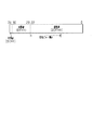
【0003】
図8に、こうした浮動小数点型データの1つであるIEEE754の規格に従って構成される単精度記憶形式のデータについて、そのフォーマットを示す。同図8に示されるように、単精度記憶形式のデータは、4バイトからなり、1ビットの符号部と、8ビットの指数部と、23ビットの仮数部とを有している。このように、図8に示す単精度記憶形式の浮動小数点型データにあっては、仮数部が23ビットで構成される。このため、この浮動小数点型データを用いることで、「1/223≒0.0000001」の精度、すなわち小数点以下7桁の精度で演算が実施されることとなる。
【0004】
【特許文献1】
特開2001―282505号公報
【0005】
【発明が解決しようとする課題】
ところで、上記電子制御装置は通常、各種制御の実行のために、所定のマップ点と同マップ点におけるマップ値との関係を定めたマップデータが記憶されたROM(Read Only Memory)を備えている。そして、各マップ点が与えられることに基づき上記マップ値を算出すると共に、これら各マップ点間の値に対しては、該当するマップ値の補間値を算出することで所望の値を得るようにしている。
【0006】
ただし、例えば上記単精度記憶形式のデータを用いてマップを構成すると、各マップ点及びマップ値にそれぞれ4バイトずつのデータが必要となる。このため、各種プログラムやマップデータを記憶する上記ROMにおいては、マップデータを記憶するための領域が自ずと拡大することとなる。特に近年、例えば車載エンジンの制御の複雑化等に起因して、上記ROMに格納されるマップの数も増大する傾向にあり、こうした問題は深刻である。
【0007】
本発明は、こうした実情に鑑みてなされたものであり、その目的は、浮動小数点型データを用いた演算に採用されるマップデータについてその好適な削減を図ることのできる電子制御装置を提供することにある。
【0008】
【課題を解決するための手段】
こうした目的を達成すべく請求項1記載の電子制御装置では、浮動小数点型のデータからなるマップ点及び該マップ点に対応した整数型のデータからなるマップ値を備えて構成されるマップデータについて、前記マップ値を整数型のデータから浮動小数点型のデータに変換するとともに、この変換した浮動小数点型データと前記マップ値の整数型のデータの最下位ビットに対応する物理量の値を表現する浮動小数点型のデータであるLSBデータとを用いて前記マップデータの補間値に対応する物理量の値を表現する浮動小数点型のデータを生成する変換手段を備える。これにより、電子制御装置内に記憶されるマップデータのうち、少なくともマップ値を整数型のデータとすることができる。したがって、電子制御装置内に記憶されるデータ量を好適に削減することができるようになる。また、マップ点については浮動小数点型のデータを用いることで、マップ点に対応する物理量が広帯域にわたる場合であれ、これを簡易且つ精度よく表現することができるようになる。さらに、マップ値の整数型のデータは、直接的に物理量を表現することなくこれを間接的に表現するものとすることができる。すなわち、マップ値の整数型のデータは、LSBデータを介して所望の物理量を表現する浮動小数点型のデータと対応付けられることとなる。したがって、LSBデータを用いることで、マップ値の整数型のデータに基づき、マップデータの補間値に対応する物理量の値を表現する浮動小数点型のデータを生成することができるようになる。
【0013】
さらに、請求項1記載の電子制御装置の変換手段は、電子制御装置に入力される検出値から、マップデータのうち当該検出値に近接する2つのマップ点を求め、当該2つのマップ点から補間係数を算出する補間係数算出手段を有し、前記変換手段は、算出した補間係数と前記変換した浮動小数点型のデータとを用いて前記マップデータの補間値を演算するとともに、前記LSBデータと該演算した補間値のデータとを用いて前記マップデータの補間値に対応する物理量の値を表現する浮動小数点型のデータを生成する。このように、入力された検出値に近接する2つのマップ点から補間係数を求め、当該補間係数を用いて浮動小数点型のデータにて補間値を演算した後、物理量を表現するデータに変換するために、補間値の演算の前に物理量を表現するデータに変換する場合と比較して、物理量を表現するデータに変換する処理数を低減することができる。
【0014】
また、請求項2記載の電子制御装置では、前記マップデータの補間値に対応する物理量の値を表現する浮動小数点型のデータの生成を、前記LSBデータを用いて前記演算した補間値のデータの論理値を対応する物理量の値に一旦変換し、且つこの変換した値に前記マップデータに対応して設けられたオフセット値を加算することで行う。このように、オフセット値を用いることで、マップ値とする整数型のデータに基づき物理量をより適切に表現することができるようになる。
【0017】
また、請求項3記載の電子制御装置では、前記変換手段は、前記マップ値とする整数型のデータについての型情報を示すIDデータに基づき、同マップ値とする整数型のデータを前記浮動小数点型のデータに変換するものである。これにより、マップ値として用いる整数型のデータとして、様々な型のデータを用いた場合であれ、これらに適切に対処することができるようになる。
【0018】
また、請求項4記載の電子制御装置では、前記変換手段を、アセンブリ言語にて記述されたプログラムを用いて前記変換を実行するものとした。これにより、C言語等、高水準言語を用いて記述したプログラムと比較して、プログラムの冗長性を低減することができ、処理速度を向上させることができる。
【0024】
【発明の実施の形態】
以下、本発明にかかる電子制御装置を車載エンジンシステムを制御する電子制御装置に適用した一実施形態について、図面を参照しつつ説明する。
【0025】
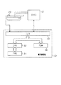
図1は、本実施形態の構成を示すブロック図である。図1に示されるエンジンシステムは、エンジン2と同エンジン2へ燃料を供給する燃料タンク4とを備えて構成されている。ここでエンジン2は、例えばガソリン噴射式内燃機関やディーゼル噴射式内燃機関である。
【0026】
こうしたエンジンシステムを制御する電子制御装置10は、中央処理装置(CPU)12や浮動小数点演算プロセッサ(FPU:Floating-Point Unit)14、読み取り専用記憶装置(ROM)16、入出力装置(I/O)18を備えている。
【0027】
ここで、中央処理装置12は、整数型にて表現されるデータを演算する機能を有する。一方、浮動小数点演算プロセッサ14は、浮動小数点型のデータ(詳しくは、先の図8に示したIEEE754に従って構成される単精度記憶形式のデータ)を演算する機能を有する。また、読み取り専用記憶装置16には、電子制御装置10の行うエンジンシステムの制御についてのプログラム等が記憶されている。なお、これらプログラムは、中央処理装置12や浮動小数点演算プロセッサ14によって実行される。
【0028】
上記構成を有する電子制御装置10には、エンジン2の運転状態や運転環境を検出する各種センサの検出値や燃料タンク4の燃料残量を検出する残量センサ20の検出結果が入力される。そして、電子制御装置10では、これら検出結果に基づき各種演算やエンジンシステムの各種制御を行う。
【0029】
特に電子制御装置10では、上記読み取り専用記憶装置16に様々なマップを備えており、上記各種制御等にかかる演算においてこのマップを用いた演算を行う。詳しくは、上記読み取り専用記憶装置16には、浮動小数点演算に用いられる様々なマップデータが記憶されており、これらは浮動小数点演算プロセッサ14にて演算される。ここで、上記残量センサの検出値に基づき燃料タンク4の燃料残量を演算する処理を例として、本実施形態にかかるマップ演算について詳細に説明する。ちなみに、こうして算出される燃料残量の値は、例えば適宜の表示器へ出力される。
【0030】
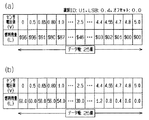
図2(a)に、上記読み取り専用記憶装置16に記憶されている燃料残量の算出に用いるマップデータを示す。同図2(a)に示されるように、このマップデータは、上記残量センサ20の検出値(電圧値)が所定の値となる25個の格子点をマップ点とし、これら検出値に対応した燃料残量をマップ値としている。
【0031】
ここで、25個のマップ点のそれぞれは、先の図8に示したフォーマットを有する浮動小数点型にて表現されているデータである。これら各データは、浮動小数点型のデータにて実際の物理量の値を表現しているため、図2(a)では、便宜上10進数表示としている。
【0032】
一方、マップ値は、整数型にて表現されたデータである。詳しくは、この整数型のデータは、U1(unsigned 1byte)形式のデータ(符号を伴わない1バイトのデータ)である。ちなみに、図2(a)中、「$」は、16進数であることを示している。
【0033】
更に、上記読み取り専用記憶装置16には、マップデータとともに、次のデータが記憶されている。
IDデータ:マップ値を表現するデータの型情報を示すデータ。このデータのデータ量は1バイトである。
LSBデータ:整数型のデータの最下位ビットに対応する物理量の値を表現する浮動小数点型のデータ(先の図8に示したフォーマットを有するデータ)。ちなみに、図2(a)に示すマップデータに対応するLSBデータでは、これは「0.4(10進数表示)」となっている。
オフセット値を示すデータ:マップ値が上記LSBデータを用いて変換されたデータと物理量の値との差を表現する浮動小数点型のデータ(先の図8に示したフォーマットを有するデータ)。すなわち、上記マップ値は、浮動小数点型のデータに変換された後、LSBデータを用いて更に変換され、オフセット値が加算されることで物理量の値となる。ちなみに、図2(a)に示すマップデータに対応するオフセット値を示すデータは、「0.0(10進数表示)」となっている。
【0034】
上記LSBデータやオフセット値を有することで、マップ値を物理量の値を表現する浮動小数点型のデータとすることができる。すなわち、例えばセンサ電圧値「0.8」に対応する燃料残量「$8C」は、2進数表示で「10001100」であり、10進数表示で「140」である。これは、LSBデータを用いて変換されることで「56(10進数表示)」となり、オフセット値を加えて物理量の値「56(10進数表示)」となる。
【0035】
ちなみに、浮動小数点演算プロセッサを搭載する従来の電子制御装置では、こうしたマップデータは、図2(b)に示すようにマップ点、マップ値ともに浮動小数点型にて表現されていた(図2(b)では、便宜上、10進数表示)。このため、各マップ点及びマップ値にそれぞれ4バイトのデータが必要となり、図2(b)に示すマップデータとしては、200バイトのデータを必要とすることとなる。
【0036】
これに対し、図2(a)に示すマップデータでは、各マップ点については各4バイトのデータが必要であるが、各マップ値については各1バイトのデータを要するのみである。そして、IDデータに1バイト、LSBデータ及びオフセットデータに4バイト必要であるため、これら各データとマップデータとの合計のデータ量は、「25×4+25×1+1+4+4=134」バイトとなる。
【0037】
したがって、本実施形態によれば、マップにかかるデータ量を削減することが可能となっている。
なお、上記読み取り専用記憶装置16には、必ずしも図2(a)に示すものと同一のデータフォーマットを有するものに限らず、例えばマップ値が2バイトの整数型のデータにて表現されたものや、マップ点及びマップ値が全て浮動小数点型のデータにて表現されたもの等も記憶されている。
【0038】
以下、本実施形態にかかるマップを用いた演算について、図2(a)に示すマップデータを用いた場合を例として詳細に説明する。
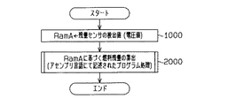
図3は、本実施形態における燃料残量の算出の処理手順を示すフローチャートである。この処理は、所定の周期で繰り返し実行される。
【0039】
すなわち、この一連の処理においては、先ずステップ1000において、上記残量センサ20の検出値が、電子制御装置10内において、先の図8に示したフォーマットを有する浮動小数点型のデータRamAに変換される。
【0040】
次に、ステップ2000において、データRamAに基づいて燃料残量が算出された後、この一連の処理を一旦終了する。なお、図3のステップ2000にかかる処理は、アセンブリ言語にて記述されたプログラムを用いて行われるようにする。すなわち、上記読み取り専用記憶装置16には、ステップ2000に示す処理に対応するプログラムとして、アセンブリ言語にて記述されたプログラムを記憶しておく。このように、アセンブリ言語にて記述されたプログラムは、C言語等の高水準言語にて記述されたプログラムと比較して、冗長性が低減されるため、プログラム処理の処理速度の向上が図られる。
【0041】
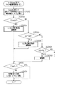
ここで、データRamAに基づいた燃料残量の算出にかかる処理について、図4を用いて説明する。図4は、電子制御装置10の備えるマップについての演算処理を行う共通の処理手順を示すフローチャートである。この図4に示す処理は、全てのマップデータに対して共通の単一のプログラムである。ここでは、この図4の処理が、データRamが上記残量センサ20の検出値である燃料残量の算出にかかる処理である場合を、換言すれば先の図3に示したステップ2000の処理の詳細である場合を例として説明することとなる。
【0042】
この一連の処理においては、先ずステップ2100において、データRamAに基づき、上記残量センサ20の検出値に最も近い2つのマップ点を指示するために用いる近接マップ点指示値Indexと、同検出値に応じた補間態様を定める補間係数Deltaとを算出する。
【0043】
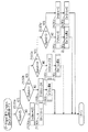
詳しくは、このステップ2100の処理は、図5に示す処理にて示される。ここで、この図5に示される処理について説明する。
この図5に示す一連の処理においては、ステップ2110a〜2110yまでの処理において、浮動小数点演算プロセッサ14にて上記データRamAと近似するマップ点を検索する処理を行う。そして、これらステップ2110a〜2110yまでの処理に基づき、ステップ2120a〜2120zのいずれかにおいて、中央処理装置12にてデータRamAに最も近い2つのマップ点を指示するために用いる近接マップ点指示値Indexの値を定める。例えば、ここでは、センサ電圧値が「5.0」以上のときには近接マップ点指示値Indexの値を「25」とする。また、例えば、センサ電圧値が「5.0」と「4.8」との間にあるときには、近接マップ点指示値Indexの値を「24」とする。なお、この近接マップ点指示値Indexは、整数型のデータとする。
【0044】
こうして近接マップ点指示値Indexの値を設定した後、ステップ2130a〜2130zのいずれかにおいて、浮動小数点演算プロセッサ14にて上記検出値に応じた補間態様を定める補間係数Deltaを算出する。そして、これらステップ2130a〜2130zのいずれかにおいて補間係数Deltaの値を算出した後、先の図4に示したステップ2100に戻る。
【0045】
なお、ステップ2130a又は2130zにおいては、検出値(データRamA)が図2(a)にて定義されるマップ点の最大値以上であるか、最小値以下であるため、補間係数Deltaを「0」とする。一方、ステップ2130b〜2130yにおいては、検出値(データRamA)が図2(a)にて定義される2つのマップ点間にある場合であるため、補間係数Deltaを図6に示す処理にて算出するようにする。
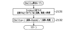
【0046】
すなわち、図6に示す一連の処理では、まずステップ2131において、中央処理装置12にて、近接マップ点指示値Indexに基づいて検出値(データRamA)と近接する2つのマップ点を取得する。すなわち、例えば検出値が「0.9(10進数表示)」である場合、近接するマップ点として高値「1.0(10進数表示)」と低値「0.8(10進数表示)」とを取得する。なお、検出値がマップ点の1つの一致するときには、低値としてそのマップ点を選択するようにする。
【0047】
次に、ステップ2132において、浮動小数点演算プロセッサ14にて、補間係数Deltaを下式にて演算する。
Delta={(高値−RamA)/(高値−低値)}
こうして補間係数Deltaを算出すると、先の図5に示したステップ2130b〜2130yのいずれかに戻る。
【0048】
上記態様にてデータRamAに基づき、近接マップ点指示値Indexと補間係数Deltaとを算出すると、図4に示すステップ2100が終了する。そして、図4のステップ2200a、2200b、…2200β、…では、中央処理装置12にて、上記ステップ2100において用いたマップにおけるマップ値を表現するデータの型情報であるIDを識別する。ちなみに、ステップ2200bでは、型情報がU2(unsigned 2byte)、すなわち符号のない2バイトの整数型のデータを示すものであるか否かを判断している。また、ステップ2200βでは、型情報が浮動小数点型のデータを示すものであるか否かを判断している。
【0049】
そして、これらステップ2200a、2200b、…2200β、…において識別された型情報に基づき、ステップ2300a、2300b、…2300β、…のいずれかにおいて補間演算を行う。詳しくは、ステップ2200βにおいて浮動小数点型である旨識別されたときには、先の図6のステップ2131にて取得された2つのマップ点に対応するマップ値に基づき、浮動小数点演算プロセッサ14にて補間演算を行う。一方、ステップ2200β以外のステップにおいて、マップ値が整数型である旨識別されたときには、同マップ値を浮動小数点型に変換した後、補間演算を行う。詳しくは、マップ値が整数型である旨識別されたときに行う処理は、図7に示される処理である。以下、これについて詳述する。
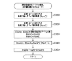
【0050】
すなわち、この一連の処理においては、まずステップ2310において、中央処理装置12にて、上記近接マップ点指示値Indexに基づき取得される隣接する2つのマップ点のうちの低値に対応するマップ値を、データRamDとして取得する。また、ステップ2320においては、中央処理装置12にて、上記近接マップ点指示値Indexに基づき取得される隣接する2つのマップ点のうちの高値に対応するマップ値を、データRamEとして取得する。
【0051】
次に、ステップ2330においては、これら整数型で表現されているデータRamD及びデータRamEを、浮動小数点型のデータRamF及びデータRamGに変換する。
【0052】
すなわち、例えばデータRamAが「0.9(10進数表示)」である場合、データRamDが「$8C」となり、また、データRamEが「$87」となる。そして、データRamDを先の図8に示したフォーマットの浮動小数点型のデータに変換すると、「0x430c0000」となる。また、データRamEを上記フォーマットの浮動小数点型のデータに変換すると、「0x43070000」となる。
【0053】
ちなみに、この浮動小数点型のデータにおいて、先頭に「0x」が付く数字は16進数を示す。そして、符号部S、指数部E、仮数部Mとしたとき、浮動小数点型のデータは、
(−1)S×2(E-127)×(1+M)
で表される。
【0054】
したがって、例えば「0x430c0000」は、2進数では以下のようになる。
0100 0011 0000 1100 0000 0000 0000 0000
ここで、符号部S、指数部E、仮数部Mはそれぞれ以下となる。

【0055】
こうしてデータRamD及びデータRamEを、浮動小数点型のデータRamF及びデータRamGに変換すると、ステップ2340に移行する。このステップ2340においては、浮動小数点演算プロセッサ14にて、線形補間量(データRamH)を下式にて算出する。
【0056】
RamH=(RamG−RamF)×Delta
次に、データRamHを用いてステップ2350においては、浮動小数点演算プロセッサ14にて、線形補間値(データRamI)を下式にて算出する。
【0057】
RamI=RamF+RamH
なお、データRamIの表現する補間値は論理値となっている。
そして、このステップ2350の処理が終了すると、先の図4のステップ2300へ戻る。
【0058】
ちなみに、この図7に示す処理は、先の図4のステップ2200による処理によって識別された整数型のデータについての型情報に応じて、それぞれ扱う整数型のデータの型が異なることを考慮した処理を行うこととなる。実際には、この図7に示した処理は、整数型データの各型毎に各別のプログラムからなる処理とすることが望ましい。
【0059】
ここで、図4のステップ2300において補間演算を終了すると、ステップ2400に移行する。そして、このステップ2400においてIDデータが浮動小数点型であることを示すデータであるか否かを判断する。
【0060】
そして、ステップ2400においてIDデータが浮動小数点型であることを示すデータでないと判断されると、ステップ2500において、浮動小数点演算プロセッサ14にて物理量の値への変換にかかる処理を行う。これは、先の図7のステップ2350で求めたデータRamIと、上記LSBデータ、オフセット値のデータを用いて下式にて行われる。
【0061】
RamI×LSB+(オフセット値)
これにより、物理量を整数型のデータの制約の中で表現すべく、間接的な表現を用いてマップ値を作成した場合であれ、先の図2(a)に示したマップデータの補間値に対応する物理量の値を適切に求めることができるようになる。なお、このように、補間演算の後に物理量への変換を行うことで、図4に示す一連の処理にかかる演算負荷の低減を図ることができる。すなわち、ステップ2300において、補間演算に先立ち物理量へ変換する処理をすると、補間に用いる2つのデータについて物理量への変換を行う必要が生じるが、本実施形態のように補間後に物理量へ変換する処理をすることで演算負荷の低減を図ることができる。
【0062】
こうしてステップ2500の処理が終了した場合や、ステップ2400においてIDデータが浮動小数点型であることを示すデータであると判断された場合には、この一連の処理を一旦終了する。ちなみに、ステップ2300βで算出された補間値は実際の物理量の値を示すものであるため、ステップ2400においてIDデータが浮動小数点型であることを示すデータであると判断された場合には、ステップ2500の処理を行わない。
【0063】
なお、この図7に示す一連の処理の後、算出された補間値を用いるルーチンへ移行する。すなわち、補間値が先の図3のステップ2000に該当するものであるときには、同ステップ2000へ戻る。
【0064】
以上のように、本実施形態では、所定のマップデータにおいて、浮動小数点型のデータよりもデータ量の小さい整数型のデータを用いてマップ値を表現した。これにより、マップデータのデータ量を低減することが可能となる。しかも、補間演算に際し、マップ値を表現する整数型のデータを浮動小数点型のデータに変換した。このため、全てを浮動小数点型で表現した場合の様々な効果を略同等に得ることができる。
【0065】
ちなみに、マップ値を予め浮動小数点型で表現した場合と本実施形態の場合とでは、これらマップ値が同一である限り、これらマップ値を用いて算出された補間値は同一となる。すなわち、マップ値を整数型とするとともに中央処理装置12にて終始整数型のデータを扱った場合と比較して、算出される補間値の精度を向上させることができる。
【0066】
また、図4にて示したマップ補間値を算出する処理を、全てのマップについて共通としたために、マップ補間にかかるプログラムのデータ量を削減することもできる。更に、この図4においては、IDデータの識別により様々な型のデータに対応することができるようにしたため、マップデータの型が代わった場合であれ、プログラムを変更することなく、IDデータの定義書き換えで対応することができる。
【0067】
以上詳述した本実施形態によれば、以下の効果が得られるようになる。
(1)マップ値を整数型にて表現するとともに、これを整数型から浮動小数点型に変換するようにした。これにより、マップを用いた演算として浮動小数点演算を行いつつも、マップデータのデータ量を好適に削減することができるようになる。
【0068】
(2)マップ点を浮動小数点型にて表現するとともに、マップ値を整数型にて表現した。これにより、マップ値のデータ量をマップ点のデータ量よりも小さくすることができる。また、マップ点については浮動小数点型のデータを用いることで、マップ点に対応する物理量が広帯域にわたる場合であれ、これを簡易且つ精度よく表現することができるようになる。
【0069】
(3)LSBデータを用いて浮動小数点型に変換されたマップ値に関するデータを物理量の値を表現するデータに変換するようにした。これにより、マップ値を表現する整数型のデータは、直接的に物理量を表現することなくこれを間接的に表現するものとすることができる。
【0070】
(4)オフセット値を用いることで、整数型のデータに基づき物理量をより適切に表現することができるようになる。
(5)マップ値に関する浮動小数点型のデータを補間演算した後、物理量を表現するデータに変換するようにした。このため、補間演算の前に物理量を表現するデータに変換する場合と比較して、物理量を表現するデータに変換する処理数を低減することができる。
【0071】
(6)マップ値を表現するデータについての型情報を示すIDデータに基づき、整数型のデータを浮動小数点型のデータに変換するようにした。これにより、マップ値を表現するデータとして、様々な型のデータを用いた場合であれ、これらに適切に対処することができるようになる。
【0072】
(7)図4〜図7にかかる処理を、アセンブリ言語にて記述されたプログラムを用いて行った。これにより、高水準言語にて記述されるプログラムと比較して、プログラムの冗長性を低減することができ、処理速度を向上させることができる。
【0073】
なお、上記実施形態は、以下のように変更して実施してもよい。
・上記実施形態では、整数型としてU1、U2を例示したがこれに限らない。例えば、S1(signed 1bitye:符号を伴う1バイトのデータ)や、S2(signed 2bitye:符号を伴う2バイトのデータ)等でもよい。
【0074】
・マップ値が整数型にて表現されたマップデータのみを備えるようにしてもよい。この場合、浮動小数点型のデータを示すものであるか否かの処理や、浮動小数点型のデータであるときの補間演算処理、物理量の値への変換を行うか否かを判断する処理(図4のステップ2200β、2300β、2400)等を行うことを禁止する禁止手段を有しなくてもよい。
【0075】
・単一の整数型にて表現されたマップデータのみを扱うならIDデータにてマップ値のデータの型情報を識別する処理を行う機能を有しなくてもよい。
・補間演算に先立ち、LSBデータ等を用いてマップ値を物理量の値に変換する処理を行うようにしても、上記実施形態の上記(1)の効果等を得ることはできる。
【0076】
・マップ値をLSBデータを用いて変換させるのみで物理量の値を表現できるなら、オフセット値のデータを有しなくてもよい。
・更に、整数型のデータにてマップ値として所望される物理量の値を表現することができるなら、LSBデータを有しなくてもよい。この場合であれ、マップ値を浮動小数点型のデータに変換することで、補間値の算出精度を向上させることはできる。
【0077】
・上記実施形態では、マップ点を浮動小数点型のデータとするとともにマップ値を整数型のデータとしたが、マップ点を整数型のデータとするとともにマップ値を浮動小数点型のデータとしてもよい。これによっても、マップ点を浮動小数点型のデータに変換する処理を施すことで、補間値の算出精度を向上させることができる。なお、この際、マップ点を表現する整数型のデータの最下位ビットに対応する物理量の値を表現する浮動小数点型のデータであるLSBデータを備えることで、所望する物理量の値を表現する浮動小数点型のデータとマップ点とを的確に対応付けることができる。更に、オフセット値に関する浮動小数点型のデータを有するようにすれば、所望する物理量の値を表現する浮動小数点型のデータとマップ点とをいっそう的確に対応付けることができる。ちなみにこれは、マップ点を整数型で十分に表現することができ、同マップ点に対応するマップ値が広帯域にわたる場合や微小な数値にて表現することが望まれる場合に特に有効である。
【0078】
・マップ点及びマップ値をいずれも整数型にて表現するようにしてもよい。この場合であれ、これらマップ点及びマップ値を浮動小数点型のデータに変換するようにすれば、補間値を精度よく算出することができる。しかも、この場合、マップデータのデータ量をいっそう削減することができる。
【0079】
・マップ値の補間は、上記実施形態で例示したように線形補間に限らない。
・浮動小数点型のデータとしては、単精度記憶形式のものに限らず、例えば倍精度記憶形式のものであってもよい。
【0080】
・マップ点及びマップ値の少なくとも一方を整数型から浮動小数点型に変換する変換手段としては、上記実施形態のように中央処理装置及び浮動小数点演算プロセッサを備えて構成されるものに限らない。例えば浮動小数点演算プロセッサと専用のハードウェアとを備えて構成されるものであってもよい。また、こうした変換手段は、必ずしもアセンブリ言語で記述されたプログラムを備えるものに限らない。
【0081】
・マップデータやLSBデータ、オフセット値に関するデータ等を記憶する記憶装置としては、ROMに限らない。
・更に、浮動小数点演算機能を有して所定のプログラムに従った各種演算及び制御を実行する電子制御装置としては、エンジンシステムを制御対象とするものに限らず、例えば車両の任意箇所を制御するものであってもよい。
【図面の簡単な説明】
【図1】本実施形態にかかる電子制御装置の構成を示すブロック図。
【図2】同実施形態にかかる残量センサの検出値と燃料残量との関係を定義するマップを示す図。
【図3】同実施形態にかかる燃料残量の算出の処理手順を示すフローチャート。
【図4】同実施形態にかかるマップ補間値の算出の処理手順を示すフローチャート。
【図5】同実施形態にかかるマップ補間のための演算処理の手順を示すフローチャート。
【図6】同実施形態にかかるマップ補間のための演算処理の手順を示すフローチャート。
【図7】同実施形態にかかるマップ補間演算の処理手順を示すフローチャート。
【図8】単精度記憶形式の浮動小数点データのフォーマットを示す図。
【符号の説明】
2…エンジン、4…燃料タンク、10…電子制御装置、12…中央処理装置、14…浮動小数点演算プロセッサ、16…読み取り専用記憶装置、18…入出力装置、20…残量センサ。[0001]
BACKGROUND OF THE INVENTION
The present invention relates to an electronic control device that has a floating point arithmetic function and executes various arithmetic operations and controls according to a predetermined program.In placeRelated.
[0002]
[Prior art]
In recent years, electronic control devices used for in-vehicle engine control and the like have also been put into practical use that use floating point type data instead of integer type data (fixed point type data) for execution of various operations. (For example, refer to Patent Document 1). By using this floating point type data, it becomes possible to perform a calculation with higher accuracy than that using integer type data.
[0003]
FIG. 8 shows the format of single-precision storage format data configured in accordance with the IEEE 754 standard, which is one of such floating point type data. As shown in FIG. 8, single precision storage format data is composed of 4 bytes, and has a 1-bit sign part, an 8-bit exponent part, and a 23-bit mantissa part. As described above, in the floating-point data in the single-precision storage format shown in FIG. 8, the mantissa part is composed of 23 bits. Therefore, by using this floating point type data, “1/2twenty threeThe calculation is performed with an accuracy of “≈0.0000001”, that is, with an accuracy of 7 digits after the decimal point.
[0004]
[Patent Document 1]
JP 2001-282505 A
[0005]
[Problems to be solved by the invention]
By the way, the electronic control device usually includes a ROM (Read Only Memory) in which map data defining a relationship between a predetermined map point and a map value at the same map point is stored for executing various controls. . Then, the map value is calculated based on the given map points, and a desired value is obtained by calculating an interpolated value of the corresponding map value for the values between these map points. ing.
[0006]
However, for example, when a map is constructed using data in the above single precision storage format, 4 bytes of data are required for each map point and map value. For this reason, in the ROM for storing various programs and map data, the area for storing the map data naturally expands. In particular, in recent years, for example, the number of maps stored in the ROM tends to increase due to, for example, complicated control of the vehicle-mounted engine, and such a problem is serious.
[0007]
The present invention has been made in view of such circumstances, and an object of the present invention is to provide an electronic control device that can achieve a suitable reduction of map data employed in computation using floating point type data.PlaceIt is to provide.
[0008]
[Means for Solving the Problems]
In order to achieve such an object, in the electronic control device according to claim 1,Consists of floating point type dataCorresponding to the map point and the map pointConsists of integer type dataAbout map data configured with map values,in frontMapThe valueConvert integer data to floating point dataAnd the interpolated value of the map data using the converted floating point type data and LSB data which is a floating point type data representing the value of the physical quantity corresponding to the least significant bit of the integer type data of the map value Generates floating-point data representing the value of the physical quantity corresponding toConversion means is provided. Thereby, at least the map data stored in the electronic control unitMap valueCan be integer data. Therefore, the amount of data stored in the electronic control device can be suitably reduced.Further, by using floating point type data for the map points, even if the physical quantity corresponding to the map points covers a wide band, this can be expressed easily and accurately. Furthermore, the integer data of the map value can be expressed indirectly without directly expressing the physical quantity. That is, the integer data of the map value is associated with the floating-point data that expresses a desired physical quantity via the LSB data. Therefore, by using the LSB data, it becomes possible to generate floating point type data representing a physical quantity value corresponding to the interpolation value of the map data based on the integer type data of the map value.
[0013]
further,Claim1Electronic control device as describedThe conversion means includes interpolation coefficient calculation means for obtaining two map points close to the detection value from the detection values input to the electronic control unit and calculating an interpolation coefficient from the two map points. AndThe converting means includesCalculated interpolation coefficient andThe converted floating point type dataWhenIs used to calculate an interpolation value of the map data, and floating point type data expressing a physical quantity value corresponding to the interpolation value of the map data using the LSB data and the calculated interpolation value data. Generate. in this way,An interpolation coefficient is obtained from two map points close to the input detection value, and the interpolation coefficient is used.After calculating the interpolation value with floating point type data, express the physical quantity compared to the case where it is converted to the data expressing the physical quantity before calculating the interpolation value in order to convert it into the data expressing the physical quantity. The number of processes converted into data can be reduced.
[0014]
Claims2In the electronic control device described above, the generation of the floating point type data representing the physical quantity value corresponding to the interpolation value of the map data corresponds to the logical value of the interpolation value data calculated using the LSB data. This is performed by once converting into a physical quantity value and adding an offset value provided corresponding to the map data to the converted value. As described above, by using the offset value, the physical quantity can be expressed more appropriately based on the integer type data as the map value.
[0017]
Claims3In the electronic control device described above, the conversion unit converts the integer type data as the map value into the floating point type data based on ID data indicating type information about the integer type data as the map value. To do. As a result, even when various types of data are used as integer type data used as the map value, it is possible to appropriately deal with them.
[0018]
Claims4In the described electronic control device, the conversion means executes the conversion using a program written in an assembly language. Thereby, compared with a program described using a high-level language such as C language, the redundancy of the program can be reduced and the processing speed can be improved.
[0024]
DETAILED DESCRIPTION OF THE INVENTION
Hereinafter, an embodiment in which an electronic control device according to the present invention is applied to an electronic control device that controls an in-vehicle engine system will be described with reference to the drawings.
[0025]
FIG. 1 is a block diagram showing the configuration of the present embodiment. The engine system shown in FIG. 1 includes an
[0026]
An
[0027]
Here, the
[0028]
The
[0029]
In particular, the
[0030]
FIG. 2A shows map data used for calculating the remaining amount of fuel stored in the read-
[0031]
Here, each of the 25 map points is data expressed in a floating-point type having the format shown in FIG. Since each of these data expresses the actual physical quantity value as floating point type data, in FIG. 2A, it is displayed in decimal notation for convenience.
[0032]
On the other hand, the map value is data expressed in an integer type. Specifically, the integer type data is U1 (unsigned 1 byte) format data (1 byte data without a sign). Incidentally, “$” in FIG. 2A indicates a hexadecimal number.
[0033]
Further, the read-
ID data: Data indicating type information of data representing a map value. The data amount of this data is 1 byte.
LSB data: Floating point type data (data having the format shown in FIG. 8) that represents the value of a physical quantity corresponding to the least significant bit of integer type data. Incidentally, in the LSB data corresponding to the map data shown in FIG. 2A, this is “0.4 (decimal number display)”.
Data indicating an offset value: Floating point type data (data having the format shown in FIG. 8) that expresses the difference between the map value converted from the LSB data and the physical quantity value. That is, the map value is converted into floating point type data, further converted using LSB data, and an offset value is added to obtain a physical quantity value. Incidentally, the data indicating the offset value corresponding to the map data shown in FIG. 2A is “0.0 (decimal number display)”.
[0034]
By having the LSB data and the offset value, the map value can be made to be a floating point type data representing a physical quantity value. That is, for example, the remaining fuel amount “$ 8C” corresponding to the sensor voltage value “0.8” is “10001100” in binary notation and “140” in decimal notation. This is converted to “56 (decimal number display)” by being converted using the LSB data, and becomes the physical quantity value “56 (decimal number display)” by adding the offset value.
[0035]
Incidentally, in a conventional electronic control device equipped with a floating-point arithmetic processor, such map data is represented in a floating-point type as shown in FIG. 2B (see FIG. 2B). ), For convenience, decimal number display). Therefore, 4 bytes of data are required for each map point and map value, and 200 bytes of data are required as the map data shown in FIG.
[0036]
On the other hand, the map data shown in FIG. 2A requires 4 bytes of data for each map point, but only 1 byte of data for each map value. Since 1 byte is required for ID data and 4 bytes are required for LSB data and offset data, the total amount of data and map data is “25 × 4 + 25 × 1 + 1 + 4 + 4 = 134” bytes.
[0037]
Therefore, according to this embodiment, it is possible to reduce the data amount concerning a map.
The read-
[0038]
Hereinafter, the calculation using the map according to the present embodiment will be described in detail by taking as an example the case of using the map data shown in FIG.
FIG. 3 is a flowchart showing a processing procedure for calculating the remaining fuel amount in the present embodiment. This process is repeatedly executed at a predetermined cycle.
[0039]
That is, in this series of processing, first, in
[0040]
Next, in
[0041]
Here, processing related to calculation of the remaining amount of fuel based on the data RamA will be described with reference to FIG. FIG. 4 is a flowchart illustrating a common processing procedure for performing arithmetic processing on a map included in the
[0042]
In this series of processing, first, in step 2100, based on the data RamA, the proximity map point instruction value Index used for indicating the two map points closest to the detection value of the remaining
[0043]
Specifically, the processing in step 2100 is shown by the processing shown in FIG. Here, the process shown in FIG. 5 will be described.
In the series of processing shown in FIG. 5, in the processing from
[0044]
After setting the value of the proximity map point instruction value Index in this way, in any of
[0045]
In
[0046]
That is, in the series of processing shown in FIG. 6, first, in
[0047]
Next, in step 2132, the floating-
Delta = {(high value−RamA) / (high value−low value)}
When the interpolation coefficient Delta is calculated in this way, the process returns to one of
[0048]
When the proximity map point instruction value Index and the interpolation coefficient Delta are calculated based on the data RamA in the above manner, step 2100 shown in FIG. 4 ends. Then, in
[0049]
Then, based on the type information identified in these
[0050]
That is, in this series of processing, first, in
[0051]
Next, in
[0052]
That is, for example, when the data RamA is “0.9 (decimal notation)”, the data RamD is “$ 8C”, and the data RamE is “$ 87”. Then, when the data RamD is converted into the floating-point type data having the format shown in FIG. 8, “0x430c0000” is obtained. Further, when the data RamE is converted into the floating-point data of the above format, “0x43070000” is obtained.
[0053]
Incidentally, in this floating point type data, a number preceded by “0x” indicates a hexadecimal number. When the sign part S, the exponent part E, and the mantissa part M are used, the floating-point data is
(-1)S× 2(E-127)× (1 + M)
It is represented by
[0054]
Therefore, for example, “0x430c0000” is as follows in binary number.
0100 0011 0000 1100 0000 0000 0000 0000
Here, the sign part S, the exponent part E, and the mantissa part M are as follows.
[0055]
When the data RamD and the data RamE are thus converted into the floating-point data RamF and the data RamG, the process proceeds to step 2340. In
[0056]
RamH = (RamG-RamF) × Delta
Next, in
[0057]
RamI = RamF + RamH
Note that the interpolation value represented by the data RamI is a logical value.
When the processing in
[0058]
Incidentally, the process shown in FIG. 7 is a process that takes into account that the type of integer type data to be handled differs according to the type information about the integer type data identified by the process in
[0059]
Here, when the interpolation calculation is completed in step 2300 in FIG. 4, the process proceeds to step 2400. In
[0060]
If it is determined in
[0061]
RamI × LSB + (offset value)
As a result, even if the map value is created using indirect expression to express the physical quantity within the constraints of the integer type data, the interpolation value of the map data shown in FIG. The value of the corresponding physical quantity can be obtained appropriately. In this way, by performing the conversion to the physical quantity after the interpolation calculation, it is possible to reduce the calculation load for the series of processes shown in FIG. That is, in step 2300, if the process of converting to a physical quantity is performed prior to the interpolation calculation, it is necessary to convert the two data used for the interpolation into a physical quantity. However, the process of converting to a physical quantity after the interpolation as in this embodiment is performed. By doing so, the calculation load can be reduced.
[0062]
When the processing of
[0063]
After the series of processing shown in FIG. 7, the routine proceeds to a routine that uses the calculated interpolation value. That is, when the interpolated value corresponds to step 2000 in FIG.
[0064]
As described above, in the present embodiment, the map value is expressed using integer type data having a smaller data amount than the floating point type data in the predetermined map data. As a result, the amount of map data can be reduced. In addition, in the interpolation operation, the integer type data representing the map value is converted to the floating point type data. For this reason, various effects when all are expressed in the floating-point type can be obtained substantially equivalently.
[0065]
Incidentally, in the case where the map values are expressed in the floating point type in advance and the case of this embodiment, the interpolation values calculated using these map values are the same as long as these map values are the same. That is, the accuracy of the calculated interpolation value can be improved as compared with the case where the map value is an integer type and the
[0066]
Further, since the process for calculating the map interpolation value shown in FIG. 4 is common to all maps, the data amount of the program related to the map interpolation can be reduced. Further, in FIG. 4, since various types of data can be handled by identifying the ID data, the definition of the ID data can be defined without changing the program even if the map data type is changed. It can respond by rewriting.
[0067]
According to the embodiment described in detail above, the following effects can be obtained.
(1) The map value is represented by an integer type, and this is converted from an integer type to a floating point type. As a result, the data amount of the map data can be suitably reduced while performing the floating point calculation as the calculation using the map.
[0068]
(2) Map points are expressed in floating-point type and map values are expressed in integer type. Thereby, the data amount of the map value can be made smaller than the data amount of the map point. Further, by using floating point type data for the map points, even if the physical quantity corresponding to the map points covers a wide band, this can be expressed easily and accurately.
[0069]
(3) The data relating to the map value converted into the floating point type using the LSB data is converted into data representing the value of the physical quantity. As a result, the integer type data representing the map value can be indirectly represented without directly representing the physical quantity.
[0070]
(4) By using the offset value, the physical quantity can be expressed more appropriately based on the integer type data.
(5) The floating point type data related to the map value is interpolated and then converted to data representing a physical quantity. For this reason, compared with the case where it converts into the data expressing a physical quantity before interpolation calculation, the number of processes converted into the data expressing a physical quantity can be reduced.
[0071]
(6) Based on the ID data indicating the type information about the data representing the map value, the integer type data is converted into the floating point type data. As a result, even when various types of data are used as data representing map values, these can be appropriately dealt with.
[0072]
(7) The processes according to FIGS. 4 to 7 were performed using a program written in assembly language. Accordingly, program redundancy can be reduced and processing speed can be improved as compared with a program written in a high-level language.
[0073]
The above embodiment may be modified as follows.
-In above-mentioned embodiment, although U1 and U2 were illustrated as an integer type, it is not restricted to this. For example, S1 (signed 1 bitye: 1-byte data with a sign), S2 (signed 2 bitye: 2-byte data with a sign), or the like may be used.
[0074]
-You may make it provide only the map data by which the map value was represented by the integer type. In this case, processing for determining whether to indicate floating-point type data, interpolation calculation processing for floating-point type data, or processing for determining whether to convert to a physical value (see FIG. 4, step 2200β, 2300β, 2400) and the like may not be provided.
[0075]
If only map data expressed in a single integer type is handled, it is not necessary to have a function of performing processing for identifying type information of map value data using ID data.
Even if the process of converting the map value into a physical quantity value using LSB data or the like is performed prior to the interpolation calculation, the effect (1) of the above embodiment can be obtained.
[0076]
If the physical quantity value can be expressed only by converting the map value using the LSB data, it is not necessary to have the offset value data.
Further, if the desired physical quantity value can be expressed as a map value with integer type data, the LSB data need not be provided. Even in this case, the calculation accuracy of the interpolation value can be improved by converting the map value into the floating point type data.
[0077]
In the above embodiment, the map point is a floating point type data and the map value is an integer type data. However, the map point may be an integer type data and the map value may be a floating point type data. Also by this, the calculation accuracy of the interpolation value can be improved by performing the process of converting the map point into the floating point type data. At this time, by providing LSB data which is floating point type data representing the value of the physical quantity corresponding to the least significant bit of the integer type data representing the map point, a floating value representing the desired physical quantity value is provided. The decimal point data and the map points can be associated with each other accurately. Further, if the floating point type data relating to the offset value is provided, the floating point type data representing the desired physical quantity value and the map point can be more accurately associated with each other. Incidentally, this is particularly effective when the map point can be sufficiently expressed in an integer type, and the map value corresponding to the map point covers a wide band or is desired to be expressed with a small numerical value.
[0078]
-Both map points and map values may be expressed in integer form. Even in this case, if these map points and map values are converted into floating point type data, the interpolation values can be calculated with high accuracy. In addition, in this case, the amount of map data can be further reduced.
[0079]
The map value interpolation is not limited to linear interpolation as exemplified in the above embodiment.
The floating point type data is not limited to the single precision storage format, but may be, for example, a double precision storage format.
[0080]
The conversion means for converting at least one of the map point and the map value from the integer type to the floating point type is not limited to the one having the central processing unit and the floating point arithmetic processor as in the above embodiment. For example, it may be configured to include a floating point arithmetic processor and dedicated hardware. Further, such conversion means is not necessarily provided with a program written in assembly language.
[0081]
A storage device that stores map data, LSB data, data related to an offset value, and the like is not limited to a ROM.
In addition, the electronic control device that has a floating point arithmetic function and executes various arithmetic operations and controls according to a predetermined program is not limited to an engine system to be controlled, but controls any part of the vehicle, for example. It may be a thing.
[Brief description of the drawings]
FIG. 1 is a block diagram showing a configuration of an electronic control device according to an embodiment.
FIG. 2 is a diagram showing a map that defines a relationship between a detection value of a remaining amount sensor and a remaining amount of fuel according to the embodiment;
FIG. 3 is a flowchart showing a processing procedure for calculating a remaining amount of fuel according to the embodiment;
FIG. 4 is a flowchart showing a processing procedure for calculating a map interpolation value according to the embodiment;
FIG. 5 is a flowchart showing a procedure of calculation processing for map interpolation according to the embodiment;
FIG. 6 is a flowchart showing a procedure of calculation processing for map interpolation according to the embodiment;
FIG. 7 is an exemplary flowchart showing a map interpolation calculation processing procedure according to the embodiment;
FIG. 8 is a diagram showing a format of floating point data in a single precision storage format.
[Explanation of symbols]
DESCRIPTION OF
Claims (4)
浮動小数点型のデータからなるマップ点及び該マップ点に対応した整数型のデータからなるマップ値を備えて構成されるマップデータについて、前記マップ値を整数型のデータから浮動小数点型のデータに変換するとともに、この変換した浮動小数点型データと前記マップ値の整数型のデータの最下位ビットに対応する物理量の値を表現する浮動小数点型のデータであるLSBデータとを用いて前記マップデータの補間値に対応する物理量の値を表現する浮動小数点型のデータを生成する変換手段を備え、
該変換手段は、当該電子制御装置に入力される検出値から、前記マップデータのうち当該検出値に近接する2つの前記マップ点を求め、当該2つのマップ点から補間係数を算出する補間係数算出手段を有し、
該変換手段は、前記算出した補間係数と、前記変換した浮動小数点型のデータとを用いて前記マップ値の補間値を演算するとともに、前記LSBデータと該演算した補間値のデータとを用いて前記マップ値の補間値に対応する物理量の値を表現する浮動小数点型のデータを生成する
ことを特徴とする電子制御装置。In an electronic control device having a floating point arithmetic function and executing various arithmetic operations and controls according to a predetermined program,
For map data comprising map points consisting of floating-point data and map values consisting of integer data corresponding to the map points, the map values are converted from integer data to floating-point data And interpolating the map data using the converted floating point type data and LSB data which is a floating point type data representing the value of the physical quantity corresponding to the least significant bit of the integer type data of the map value. Conversion means for generating floating-point data representing the value of the physical quantity corresponding to the value ,
The conversion means obtains two map points close to the detected value from the detected value input to the electronic control device, and calculates an interpolation coefficient from the two map points. Having means,
The conversion means calculates the interpolation value of the map value using the calculated interpolation coefficient and the converted floating point type data, and uses the LSB data and the calculated interpolation value data. An electronic control device characterized by generating floating point type data representing a physical quantity value corresponding to an interpolation value of the map value .
請求項1記載の電子制御装置。The generation of the floating point type data representing the physical quantity value corresponding to the interpolation value of the map data temporarily converts the logical value of the calculated interpolation value data into the corresponding physical quantity value using the LSB data. The electronic control unit according to claim 1 , wherein the electronic control unit is performed by adding an offset value provided corresponding to the map data to the converted value.
請求項1または2に記載の電子制御装置。2. The conversion unit is configured to convert integer type data to be the map value into the floating point type data based on ID data indicating type information about the integer type data to be the map value. Or the electronic control apparatus of 2.
請求項1〜3のいずれかに記載の電子制御装置。 And the converting means, the electronic control device according to any one of claims 1 to 3, in which to perform the conversion using the program written in assembly language.
Priority Applications (3)
| Application Number | Priority Date | Filing Date | Title |
|---|---|---|---|
| JP2003017546A JP4228706B2 (en) | 2003-01-27 | 2003-01-27 | Electronic control device and storage device of the electronic control device |
| EP04001591.9A EP1441277B1 (en) | 2003-01-27 | 2004-01-26 | Electronic control apparatus |
| US10/764,583 US7558811B2 (en) | 2003-01-27 | 2004-01-27 | Electronic control apparatus and memory apparatus for electronic control apparatus |
Applications Claiming Priority (1)
| Application Number | Priority Date | Filing Date | Title |
|---|---|---|---|
| JP2003017546A JP4228706B2 (en) | 2003-01-27 | 2003-01-27 | Electronic control device and storage device of the electronic control device |
Publications (2)
| Publication Number | Publication Date |
|---|---|
| JP2004225668A JP2004225668A (en) | 2004-08-12 |
| JP4228706B2 true JP4228706B2 (en) | 2009-02-25 |
Family
ID=32588709
Family Applications (1)
| Application Number | Title | Priority Date | Filing Date |
|---|---|---|---|
| JP2003017546A Expired - Fee Related JP4228706B2 (en) | 2003-01-27 | 2003-01-27 | Electronic control device and storage device of the electronic control device |
Country Status (3)
| Country | Link |
|---|---|
| US (1) | US7558811B2 (en) |
| EP (1) | EP1441277B1 (en) |
| JP (1) | JP4228706B2 (en) |
Families Citing this family (5)
| Publication number | Priority date | Publication date | Assignee | Title |
|---|---|---|---|---|
| JP4645519B2 (en) * | 2006-04-27 | 2011-03-09 | 株式会社デンソー | Arithmetic processing device, control device and program |
| JP2009110353A (en) * | 2007-10-31 | 2009-05-21 | Hitachi Ltd | Microcontroller and control system |
| JP4629750B2 (en) * | 2008-03-31 | 2011-02-09 | 日立オートモティブシステムズ株式会社 | Embedded control unit |
| GB2481579B (en) * | 2010-06-25 | 2014-11-26 | Enmodus Ltd | Monitoring of power-consumption |
| CN104166535B (en) * | 2013-07-19 | 2017-07-28 | 郑州宇通客车股份有限公司 | Fixed-point processor and its overflow prevention method |
Family Cites Families (17)
| Publication number | Priority date | Publication date | Assignee | Title |
|---|---|---|---|---|
| JPS63223825A (en) | 1987-03-12 | 1988-09-19 | Nec Corp | Data type converting circuit |
| JPH0314128A (en) | 1989-06-13 | 1991-01-22 | Tomio Kurokawa | Arithmetic unit utilizing logarithmic expression numerical value |
| US5638312A (en) * | 1995-03-03 | 1997-06-10 | Hal Computer Systems, Inc. | Method and apparatus for generating a zero bit status flag in a microprocessor |
| US6144977A (en) * | 1995-07-10 | 2000-11-07 | Motorola, Inc. | Circuit and method of converting a floating point number to a programmable fixed point number |
| US5682896A (en) * | 1996-03-28 | 1997-11-04 | Diasonics Ultrasound, Inc. | Method and apparatus for generating volume flow measurement |
| US5751611A (en) | 1996-10-03 | 1998-05-12 | Prime Technology, Inc. | Display device for linearly displaying a non-linear input variable |
| CA2227531C (en) * | 1997-01-20 | 2003-03-18 | Hitachi, Ltd. | Graphics processing unit and graphics processing system |
| US6282554B1 (en) * | 1998-04-30 | 2001-08-28 | Intel Corporation | Method and apparatus for floating point operations and format conversion operations |
| JP3123047B2 (en) | 1998-10-02 | 2001-01-09 | 日本電気株式会社 | Microprocessor |
| US6757700B1 (en) * | 1999-10-28 | 2004-06-29 | Phillip Druck | Self-stabilizing, portable and efficient computer arithmetic using mappings of D Scale points |
| JP3644350B2 (en) | 2000-04-03 | 2005-04-27 | 株式会社デンソー | Automotive electronic control device with floating point arithmetic function |
| JP3551875B2 (en) * | 2000-01-11 | 2004-08-11 | 株式会社デンソー | Electronic control unit with floating point arithmetic function |
| US6671796B1 (en) * | 2000-02-25 | 2003-12-30 | Sun Microsystems, Inc. | Converting an arbitrary fixed point value to a floating point value |
| JP2002008060A (en) | 2000-06-23 | 2002-01-11 | Hitachi Ltd | Data processing method, recording medium and data processing device |
| JP2002157004A (en) | 2000-11-20 | 2002-05-31 | Denso Corp | Electronic control unit |
| US7051060B2 (en) * | 2001-09-28 | 2006-05-23 | Intel Corporation | Operand conversion optimization |
| US7236995B2 (en) * | 2002-12-27 | 2007-06-26 | Arm Limited | Data processing apparatus and method for converting a number between fixed-point and floating-point representations |
-
2003
- 2003-01-27 JP JP2003017546A patent/JP4228706B2/en not_active Expired - Fee Related
-
2004
- 2004-01-26 EP EP04001591.9A patent/EP1441277B1/en not_active Expired - Fee Related
- 2004-01-27 US US10/764,583 patent/US7558811B2/en not_active Expired - Fee Related
Also Published As
| Publication number | Publication date |
|---|---|
| JP2004225668A (en) | 2004-08-12 |
| US20040186866A1 (en) | 2004-09-23 |
| US7558811B2 (en) | 2009-07-07 |
| EP1441277A3 (en) | 2006-10-25 |
| EP1441277A2 (en) | 2004-07-28 |
| EP1441277B1 (en) | 2018-08-01 |
Similar Documents
| Publication | Publication Date | Title |
|---|---|---|
| US8484266B2 (en) | Embedded control system with floating-point conversion | |
| JP4228706B2 (en) | Electronic control device and storage device of the electronic control device | |
| JP2004135312A (en) | Image processor, image processing system, image forming apparatus, image processing method, and program | |
| KR940006026A (en) | Compilation Raster Operation Code Generation Method and System | |
| JPH1049369A (en) | Data processor | |
| US20110144927A1 (en) | Method for real time capability simulation of an air system model of an internal combustion engine | |
| JP2012185542A (en) | Code generation device and code generation program | |
| JP2001195233A (en) | Electronic controller having floating point arithmetic function | |
| JP4194433B2 (en) | Likelihood calculation apparatus and method | |
| JP3935908B2 (en) | Apparatus and method for reducing quantization error | |
| JP4534447B2 (en) | Digital data alteration detection program, alteration detection method and alteration detection device | |
| JP3465592B2 (en) | Data format converter | |
| CN109710310B (en) | Data processing method, system, terminal and storage medium for embedded environment | |
| JP3666226B2 (en) | Electronic control unit | |
| JP4196773B2 (en) | Electronic control device design and development system, program, recording medium | |
| CN117707471A (en) | Environment acquisition equipment, target equipment and data processing method and system thereof | |
| JPH0743566B2 (en) | Angle calculator | |
| JPH1027011A (en) | Programmable controller | |
| JPH09167005A (en) | Programmable controller | |
| JP6260179B2 (en) | Arithmetic apparatus and arithmetic method | |
| JP2005031847A (en) | Method, program, and device for integer arithmetic operation | |
| JP3499481B2 (en) | Data multiplier | |
| JPH07325710A (en) | Production of high-level language program simulated from assembler of fixed point arithmetic and arithmetic accuracy studying method | |
| Ndeekor | Algorithm for output of floating-point numbers in fixed-point form | |
| JP2009067071A (en) | Electronic control unit |
Legal Events
| Date | Code | Title | Description |
|---|---|---|---|
| A621 | Written request for application examination |
Free format text: JAPANESE INTERMEDIATE CODE: A621 Effective date: 20050413 |
|
| A131 | Notification of reasons for refusal |
Free format text: JAPANESE INTERMEDIATE CODE: A131 Effective date: 20070918 |
|
| A521 | Written amendment |
Free format text: JAPANESE INTERMEDIATE CODE: A523 Effective date: 20071116 |
|
| A02 | Decision of refusal |
Free format text: JAPANESE INTERMEDIATE CODE: A02 Effective date: 20080527 |
|
| A521 | Written amendment |
Free format text: JAPANESE INTERMEDIATE CODE: A523 Effective date: 20080728 |
|
| A911 | Transfer to examiner for re-examination before appeal (zenchi) |
Free format text: JAPANESE INTERMEDIATE CODE: A911 Effective date: 20080922 |
|
| TRDD | Decision of grant or rejection written | ||
| A01 | Written decision to grant a patent or to grant a registration (utility model) |
Free format text: JAPANESE INTERMEDIATE CODE: A01 Effective date: 20081111 |
|
| A01 | Written decision to grant a patent or to grant a registration (utility model) |
Free format text: JAPANESE INTERMEDIATE CODE: A01 |
|
| A61 | First payment of annual fees (during grant procedure) |
Free format text: JAPANESE INTERMEDIATE CODE: A61 Effective date: 20081124 |
|
| R150 | Certificate of patent or registration of utility model |
Ref document number: 4228706 Country of ref document: JP Free format text: JAPANESE INTERMEDIATE CODE: R150 Free format text: JAPANESE INTERMEDIATE CODE: R150 |
|
| FPAY | Renewal fee payment (event date is renewal date of database) |
Free format text: PAYMENT UNTIL: 20111212 Year of fee payment: 3 |
|
| FPAY | Renewal fee payment (event date is renewal date of database) |
Free format text: PAYMENT UNTIL: 20121212 Year of fee payment: 4 |
|
| FPAY | Renewal fee payment (event date is renewal date of database) |
Free format text: PAYMENT UNTIL: 20131212 Year of fee payment: 5 |
|
| R250 | Receipt of annual fees |
Free format text: JAPANESE INTERMEDIATE CODE: R250 |
|
| R250 | Receipt of annual fees |
Free format text: JAPANESE INTERMEDIATE CODE: R250 |
|
| R250 | Receipt of annual fees |
Free format text: JAPANESE INTERMEDIATE CODE: R250 |
|
| R250 | Receipt of annual fees |
Free format text: JAPANESE INTERMEDIATE CODE: R250 |
|
| R250 | Receipt of annual fees |
Free format text: JAPANESE INTERMEDIATE CODE: R250 |
|
| R250 | Receipt of annual fees |
Free format text: JAPANESE INTERMEDIATE CODE: R250 |
|
| LAPS | Cancellation because of no payment of annual fees |