JP4226079B2 - Writing apparatus and writing method - Google Patents
Writing apparatus and writing method Download PDFInfo
- Publication number
- JP4226079B2 JP4226079B2 JP52338098A JP52338098A JP4226079B2 JP 4226079 B2 JP4226079 B2 JP 4226079B2 JP 52338098 A JP52338098 A JP 52338098A JP 52338098 A JP52338098 A JP 52338098A JP 4226079 B2 JP4226079 B2 JP 4226079B2
- Authority
- JP
- Japan
- Prior art keywords
- area
- writing
- information
- record carrier
- unwritten
- Prior art date
- Legal status (The legal status is an assumption and is not a legal conclusion. Google has not performed a legal analysis and makes no representation as to the accuracy of the status listed.)
- Expired - Lifetime
Links
Images


Classifications
-
- G—PHYSICS
- G11—INFORMATION STORAGE
- G11B—INFORMATION STORAGE BASED ON RELATIVE MOVEMENT BETWEEN RECORD CARRIER AND TRANSDUCER
- G11B7/00—Recording or reproducing by optical means, e.g. recording using a thermal beam of optical radiation by modifying optical properties or the physical structure, reproducing using an optical beam at lower power by sensing optical properties; Record carriers therefor
- G11B7/007—Arrangement of the information on the record carrier, e.g. form of tracks, actual track shape, e.g. wobbled, or cross-section, e.g. v-shaped; Sequential information structures, e.g. sectoring or header formats within a track
- G11B7/00736—Auxiliary data, e.g. lead-in, lead-out, Power Calibration Area [PCA], Burst Cutting Area [BCA], control information
-
- G—PHYSICS
- G11—INFORMATION STORAGE
- G11B—INFORMATION STORAGE BASED ON RELATIVE MOVEMENT BETWEEN RECORD CARRIER AND TRANSDUCER
- G11B20/00—Signal processing not specific to the method of recording or reproducing; Circuits therefor
- G11B20/10—Digital recording or reproducing
- G11B20/12—Formatting, e.g. arrangement of data block or words on the record carriers
-
- G—PHYSICS
- G11—INFORMATION STORAGE
- G11B—INFORMATION STORAGE BASED ON RELATIVE MOVEMENT BETWEEN RECORD CARRIER AND TRANSDUCER
- G11B27/00—Editing; Indexing; Addressing; Timing or synchronising; Monitoring; Measuring tape travel
- G11B27/02—Editing, e.g. varying the order of information signals recorded on, or reproduced from, record carriers
- G11B27/031—Electronic editing of digitised analogue information signals, e.g. audio or video signals
- G11B27/034—Electronic editing of digitised analogue information signals, e.g. audio or video signals on discs
-
- G—PHYSICS
- G11—INFORMATION STORAGE
- G11B—INFORMATION STORAGE BASED ON RELATIVE MOVEMENT BETWEEN RECORD CARRIER AND TRANSDUCER
- G11B27/00—Editing; Indexing; Addressing; Timing or synchronising; Monitoring; Measuring tape travel
- G11B27/10—Indexing; Addressing; Timing or synchronising; Measuring tape travel
- G11B27/102—Programmed access in sequence to addressed parts of tracks of operating record carriers
- G11B27/105—Programmed access in sequence to addressed parts of tracks of operating record carriers of operating discs
-
- G—PHYSICS
- G11—INFORMATION STORAGE
- G11B—INFORMATION STORAGE BASED ON RELATIVE MOVEMENT BETWEEN RECORD CARRIER AND TRANSDUCER
- G11B27/00—Editing; Indexing; Addressing; Timing or synchronising; Monitoring; Measuring tape travel
- G11B27/10—Indexing; Addressing; Timing or synchronising; Measuring tape travel
- G11B27/11—Indexing; Addressing; Timing or synchronising; Measuring tape travel by using information not detectable on the record carrier
-
- G—PHYSICS
- G11—INFORMATION STORAGE
- G11B—INFORMATION STORAGE BASED ON RELATIVE MOVEMENT BETWEEN RECORD CARRIER AND TRANSDUCER
- G11B27/00—Editing; Indexing; Addressing; Timing or synchronising; Monitoring; Measuring tape travel
- G11B27/10—Indexing; Addressing; Timing or synchronising; Measuring tape travel
- G11B27/19—Indexing; Addressing; Timing or synchronising; Measuring tape travel by using information detectable on the record carrier
- G11B27/22—Means responsive to presence or absence of recorded information signals
-
- G—PHYSICS
- G11—INFORMATION STORAGE
- G11B—INFORMATION STORAGE BASED ON RELATIVE MOVEMENT BETWEEN RECORD CARRIER AND TRANSDUCER
- G11B27/00—Editing; Indexing; Addressing; Timing or synchronising; Monitoring; Measuring tape travel
- G11B27/10—Indexing; Addressing; Timing or synchronising; Measuring tape travel
- G11B27/19—Indexing; Addressing; Timing or synchronising; Measuring tape travel by using information detectable on the record carrier
- G11B27/28—Indexing; Addressing; Timing or synchronising; Measuring tape travel by using information detectable on the record carrier by using information signals recorded by the same method as the main recording
- G11B27/30—Indexing; Addressing; Timing or synchronising; Measuring tape travel by using information detectable on the record carrier by using information signals recorded by the same method as the main recording on the same track as the main recording
- G11B27/3027—Indexing; Addressing; Timing or synchronising; Measuring tape travel by using information detectable on the record carrier by using information signals recorded by the same method as the main recording on the same track as the main recording used signal is digitally coded
-
- G—PHYSICS
- G11—INFORMATION STORAGE
- G11B—INFORMATION STORAGE BASED ON RELATIVE MOVEMENT BETWEEN RECORD CARRIER AND TRANSDUCER
- G11B27/00—Editing; Indexing; Addressing; Timing or synchronising; Monitoring; Measuring tape travel
- G11B27/10—Indexing; Addressing; Timing or synchronising; Measuring tape travel
- G11B27/19—Indexing; Addressing; Timing or synchronising; Measuring tape travel by using information detectable on the record carrier
- G11B27/28—Indexing; Addressing; Timing or synchronising; Measuring tape travel by using information detectable on the record carrier by using information signals recorded by the same method as the main recording
- G11B27/32—Indexing; Addressing; Timing or synchronising; Measuring tape travel by using information detectable on the record carrier by using information signals recorded by the same method as the main recording on separate auxiliary tracks of the same or an auxiliary record carrier
- G11B27/327—Table of contents
- G11B27/329—Table of contents on a disc [VTOC]
-
- G—PHYSICS
- G11—INFORMATION STORAGE
- G11B—INFORMATION STORAGE BASED ON RELATIVE MOVEMENT BETWEEN RECORD CARRIER AND TRANSDUCER
- G11B27/00—Editing; Indexing; Addressing; Timing or synchronising; Monitoring; Measuring tape travel
- G11B27/36—Monitoring, i.e. supervising the progress of recording or reproducing
-
- G—PHYSICS
- G11—INFORMATION STORAGE
- G11B—INFORMATION STORAGE BASED ON RELATIVE MOVEMENT BETWEEN RECORD CARRIER AND TRANSDUCER
- G11B7/00—Recording or reproducing by optical means, e.g. recording using a thermal beam of optical radiation by modifying optical properties or the physical structure, reproducing using an optical beam at lower power by sensing optical properties; Record carriers therefor
- G11B7/007—Arrangement of the information on the record carrier, e.g. form of tracks, actual track shape, e.g. wobbled, or cross-section, e.g. v-shaped; Sequential information structures, e.g. sectoring or header formats within a track
- G11B7/0079—Zoned data area, e.g. having different data structures or formats for the user data within data layer, Zone Constant Linear Velocity [ZCLV], Zone Constant Angular Velocity [ZCAV], carriers with RAM and ROM areas
-
- G—PHYSICS
- G11—INFORMATION STORAGE
- G11B—INFORMATION STORAGE BASED ON RELATIVE MOVEMENT BETWEEN RECORD CARRIER AND TRANSDUCER
- G11B2220/00—Record carriers by type
- G11B2220/20—Disc-shaped record carriers
- G11B2220/21—Disc-shaped record carriers characterised in that the disc is of read-only, rewritable, or recordable type
- G11B2220/215—Recordable discs
- G11B2220/216—Rewritable discs
-
- G—PHYSICS
- G11—INFORMATION STORAGE
- G11B—INFORMATION STORAGE BASED ON RELATIVE MOVEMENT BETWEEN RECORD CARRIER AND TRANSDUCER
- G11B2220/00—Record carriers by type
- G11B2220/20—Disc-shaped record carriers
- G11B2220/21—Disc-shaped record carriers characterised in that the disc is of read-only, rewritable, or recordable type
- G11B2220/215—Recordable discs
- G11B2220/218—Write-once discs
-
- G—PHYSICS
- G11—INFORMATION STORAGE
- G11B—INFORMATION STORAGE BASED ON RELATIVE MOVEMENT BETWEEN RECORD CARRIER AND TRANSDUCER
- G11B2220/00—Record carriers by type
- G11B2220/20—Disc-shaped record carriers
- G11B2220/25—Disc-shaped record carriers characterised in that the disc is based on a specific recording technology
- G11B2220/2525—Magneto-optical [MO] discs
-
- G—PHYSICS
- G11—INFORMATION STORAGE
- G11B—INFORMATION STORAGE BASED ON RELATIVE MOVEMENT BETWEEN RECORD CARRIER AND TRANSDUCER
- G11B2220/00—Record carriers by type
- G11B2220/20—Disc-shaped record carriers
- G11B2220/25—Disc-shaped record carriers characterised in that the disc is based on a specific recording technology
- G11B2220/2537—Optical discs
- G11B2220/2545—CDs
-
- G—PHYSICS
- G11—INFORMATION STORAGE
- G11B—INFORMATION STORAGE BASED ON RELATIVE MOVEMENT BETWEEN RECORD CARRIER AND TRANSDUCER
- G11B2220/00—Record carriers by type
- G11B2220/20—Disc-shaped record carriers
- G11B2220/25—Disc-shaped record carriers characterised in that the disc is based on a specific recording technology
- G11B2220/2537—Optical discs
- G11B2220/2562—DVDs [digital versatile discs]; Digital video discs; MMCDs; HDCDs
- G11B2220/2575—DVD-RAMs
-
- G—PHYSICS
- G11—INFORMATION STORAGE
- G11B—INFORMATION STORAGE BASED ON RELATIVE MOVEMENT BETWEEN RECORD CARRIER AND TRANSDUCER
- G11B2220/00—Record carriers by type
- G11B2220/60—Solid state media
- G11B2220/65—Solid state media wherein solid state memory is used for storing indexing information or metadata
-
- G—PHYSICS
- G11—INFORMATION STORAGE
- G11B—INFORMATION STORAGE BASED ON RELATIVE MOVEMENT BETWEEN RECORD CARRIER AND TRANSDUCER
- G11B27/00—Editing; Indexing; Addressing; Timing or synchronising; Monitoring; Measuring tape travel
- G11B27/02—Editing, e.g. varying the order of information signals recorded on, or reproduced from, record carriers
- G11B27/031—Electronic editing of digitised analogue information signals, e.g. audio or video signals
- G11B27/036—Insert-editing
-
- G—PHYSICS
- G11—INFORMATION STORAGE
- G11B—INFORMATION STORAGE BASED ON RELATIVE MOVEMENT BETWEEN RECORD CARRIER AND TRANSDUCER
- G11B7/00—Recording or reproducing by optical means, e.g. recording using a thermal beam of optical radiation by modifying optical properties or the physical structure, reproducing using an optical beam at lower power by sensing optical properties; Record carriers therefor
- G11B7/004—Recording, reproducing or erasing methods; Read, write or erase circuits therefor
- G11B7/0045—Recording
Description
技術分野
本発明は、再書込可能型の記録担体のトラックパターンに情報ブロックを書き込む装置に関する。かかる装置には、その情報ブロックを表すマークを電磁放射ビームによって記録担体の各エリアに書き込む書込ユニットと、当該記録担体のトラック構造に基づいて書込ユニットを位置決めする位置決め手段とが設けられるものである。ここで言うところのトラック構造は、トラックパターンを示している。
本発明はまた、再書込可能型の記録担体のトラックパターンに情報ブロックを書き込む方法に関する。かかる方法においては、情報ブロックを表すマークが書込ユニット及び電磁放射ビームによって当該記録担体の各エリアに書き込まれ、またその書込ユニットが、トラックパターンを示すトラック構造に基づいて位置決めされるものである。
本発明はまた、上記書込装置に用いられる記録担体に関する。
さらに、本発明は、記録担体のトラックパターンにおける光学的読取可能なマークによって表される情報ブロックを読み取る読取手段が設けられた読取装置に関する。かかる装置には、電磁放射ビームによってマークを読み取る読取ユニットと、マークに基づいて読取ユニットを位置決めする位置決め手段とが設けられるものである。
背景技術
従来の、情報ブロックを書き込む冒頭の段落において述べたタイプの書込装置、方法及び記録担体は、US4,901,300(PHN12.398)に開示されている。この文書に記述されているシステムにおいては、情報ブロックは、記録担体のトラックパターンに記録されるものであり、光学的に読取可能なマークによって表されるものである。この記録担体は、位置情報を表す変動周波数を有するウォブリングの施されたプリグルーブの形態を採るトラック構造を有している。書込装置は、電磁放射ビームによって記録担体をスキャン(走査)しこれに伴いその反射される放射成分からトラッキング信号を得るようにした書込ヘッドと、上記位置情報に基づいてスキャン中の書込ヘッドの位置決めをなす位置決め手段とを備えている。スキャン中は、上記ウォブルがトラッキング信号に変調成分を生じさせる。この変調成分は、その成分中でコード化されている位置情報を有しており、該位置情報は、情報用に設けられたエリアの始端箇所に関しての当該トラックにおける絶対位置を示している。この各情報ブロックは、その位置情報に基づいて、必要であれば当該トラックのジャンプを用いて書込ヘッドを位置決めしつつ、それぞれのアドレスに従って所望の位置に記録担体に記録される。記録担体は、部分的に書き込まれうるものであり、この場合、マークの存在する書込エリアと、トラック構造のみ存在する未書込エリアとを有する。読取装置には、マークからトラッキング信号及び/又は位置情報を得るものがある。これら読取装置の問題は、未書込エリアにおいて位置情報を生成できない点である。それ故、部分的に書き込まれる記録担体は、確実な読み取りができない。
発明の開示
本発明の主たる目的は、部分的に書き込まれる記録担体を、より確実に読み取ることのできる手段を提供することである。
そこで、本発明の第1の態様によれば、書込装置は、情報ブロックを書き込むために使用されている前記記録担体のエリアを検出する第1検出手段と、前記使用されているエリアに隣接する未書込境界エリアを検出する第2検出手段と、前記未書込境界エリアにダミー情報を書き込む初期化手段とが設けられることを特徴としている。この発明による書込装置は、特に、マークからトラッキング信号及び位置情報を得る読取装置によって部分的書込済みの記録担体を確実に読み取ることができる、という利点がある。なぜなら、隔離された情報ブロックに隣接する境界エリアに書込がなされるからである。かかるエリアへのジャンプがなされる場合、読取ユニットは、例えば、読取ユニットを変位させるモータの速度センサから得られる距離情報に基づいて、読み取るべき情報ブロック前方で少しだけ距離の離れたところに全体的大まかな位置決めがなされる。そしてこの読取ユニットは、読み取るべき情報ブロックの前方で少しだけ距離を隔てて当該隣接エリアに到達することとなる。このエリアにおいては、ダミー情報のマークが存在しており、それ故に読取ユニットが、記録担体から読み取られた情報に基づいて通常の様式で正確に位置決めされる。また、他にも、全体的位置決め時の不正確さのために読み取るべき情報ブロックの後方に少しだけ距離を隔てて読取ユニットが位置決めされる場合のために、境界エリアが、読み取るべき情報ブロックを越えて書き込まれる、という利点がある。
注記するに、ディスク形の記録担体におけるデータ記憶用のエリアに対し、一部を実際にデータ記憶する必要がある場合はいつも、各部の連続的なフォーマット化が施されるディスク記憶システムがEP 0 328 240に記載されている。フォーマット時においてエリアは位置情報が設けられ、その後、書込動作及びこれに続く読取動作の形態によって該エリアが使用されかつ解読されるとともに、エラー制御情報が当該解読内容に基づいて発生される。本発明によるシステムにおいては、位置情報が既にトラック構造に存在し、使用されていないエリアすなわち使用されているエリアの未書込境界エリアには、ダミー情報がデータ記憶エリアの使用前または使用後において書込動作の形態で書き込まれる。
本発明による装置の一実施例は、前記第1検出手段が、前記使用されているエリアを、当該装置により受信された書込指令に基づいて検出するように構成されていることを特徴としている。こうすることにより、エリアが使用されているかどうかの事実を、記憶手段を用いることなく判定することができる、という効果を奏する。
本発明による装置の他の実施例は、前記第1検出手段が、前記使用されているエリアを、前記記録担体の使用情報に基づいて検出するように構成されていることを特徴としている。これにより、エリアが使用されているかどうかの事実を、関連のあるエリアをその本来の目的のための読み取りをなす必要なく使用情報から直接判定することができる、という効果を奏する。
本発明による装置のさらに他の実施例は、前記初期化手段は、所定の幅を有する帯状エリアに書込処理を施すように構成されていることを特徴としている。この場合、かかる未書込境界エリアは、ジャンプ後に読取装置の読取ユニットを到達(着地)させる到達エリアを形成する最小幅として少なくとも十分なものとされる。この幅は、多くの標準的読取装置でその読取ユニットがジャンプ時にこの幅の中で到達できるように選定される。これにより、部分的書込済みの記録担体は、標準的読取装置によって確実に読取可能となる。
本発明によるまた別の実施例は、前記初期化手段は、書込指令の実行後の時点で書込処理を施すように構成され、前記時点は、動作状況に基づいて決定されることを特徴としている。こうすることにより、当該初期化の性能によるユーザへの邪魔を可能な限り低減することができる。
本発明によるまたさらに他の実施例は、前記ダミー情報は、N個のダミー情報ブロックとして構成され、Nは、1以上であり、前記ダミー情報ブロックには位置情報が設けられることを特徴としている。これら隣接エリアにおいて、初期化手段は、例えばアドレスのような通常の様式の位置情報を有するダミー情報ブロックを書き込む。この実施例には、読取ユニットが、その読取ユニットの位置を通常様式にて当該位置情報に基づいて決定することができる、という利点がある。値の小さいNのもとでは、書込境界エリアは、読取ユニットが到達するのに小さすぎることがあるが、使用されている該当エリアにおける情報ブロックを読み取る前に読取手段をロックインさせるために、助走エリアが形成されることとなる。これは、当該書込エリアを検索することのできる本発明による読取装置においては有益なものである。なぜなら、読取ユニットは、この助走エリアを経て情報ブロックに接近し、トラッキング手段及び読取信号復号手段がロックインするからである。
本発明の第2の態様によれば、上記書込装置に用いられる記録担体は、前記記録担体のエリアの未書込または書込済み状態についてのステータス情報が設けられ、このステータス情報は、所定の様式で再生可能であることを特徴としている。この利点は、書込エリアを検出する検出手段によりステータス情報を再生した後には、書込装置が、書き込まれているかまたは未書込となっているかどちらかであるエリアの状態を検知しており、したがって、当該エリアが最初に読まれる必要がない故に、初期化すべきかどうかを直ちに決定することができる、という点である。これは、書込指令を実行し、必要であれば隣接領域を初期化するための時間が短くてすむ。
本発明の第3の態様によれば、読取装置に、マークが書き込まれたエリアを検索する検索手段を設けたことを特徴としている。この読取装置は、マークによってのみトラックを追従することができ、位置情報を生成することができる。接触しておらずしかも未書込エリアにより分離されているエリアが読み取られる場合、かかるエリアへのジャンプが行われると、概して読取ユニットは、読み取られるべき情報ブロックの前方に少し離れて到達することとなる。ここで、この検索手段は、例えばマークを見つけられるまで当該ジャンプの向きにさらに読取ユニットを変位させることにより書込エリアが検索される、という利点を持つ。したがって、本発明による読取装置は、部分的に書き込まれた記録担体を確実に読み取ることができるのである。
本発明のこれらの態様及びその他の態様は、以下に記述された実施例から明らかであるし、該実施例を参照して説明される。
【図面の簡単な説明】
第1図は、トラック構造が設けられた記録担体を示している。
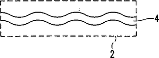
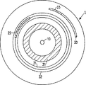
第2図は、部分的に書込済みの記録担体を示している。
第3図は、ダミー情報を有する部分的書込済みの記録担体を示している。
第4図は、情報ブロックを書き込む書込装置を示している。
第5図は、読取装置を示している。
各図において、既に説明した部分(部品)に対応する部分(部品)には同じ参照番号が付されている。
発明を実施するための最良の形態
第1a図は、記録用に形成されたトラック9と中心孔10とが設けられたディスク形記録担体1を示している。トラック9は、巻回(周回)部3による渦巻パターンに応じて形成される。トラック9は、何も記録されていない記録担体の製造において造られたトラック構造によって、記録担体に表される。トラック構造は、例えば、スキャン時に読取/書込ヘッドがトラック9を追従可能とするプリグルーブ4によって構成される。第1b図は、記録担体1の線b−bにおいて得られる断面図であり、透明基板5には、記録層6及び保護層7が設けられる。プリグルーブ4は、ピット又は凸状に形成しても良いし、その状態から遷移する材料特性を有するものとしても良い。さらに、トラック構造は、ランド及びグルーブパターンと呼ばれる凸状及び凹状の巻回部が交互に配される構成とすることができる。この構成には、巻回部毎になされるランドからグルーブへの転換或いはその逆の転換を伴う。記録層6は、知られているCD−レコーダブルのような情報の読取及び/又は書込を行う装置によって、光学的に或いは磁気光学的に書き込み可能である。かかる情報は、ブロック毎に構成され、CDにおける連続する種々の長さのピット群のように、多量の放射と少量の放射とを反射させる連続するエリア群の形態を採る光学的に読取可能なマークによって表される。このような再書込可能なディスクは、新しい高密度光ディスクであるディジタルバーサタイルディスク(DVD)のシステムにおいて提供される。第1c図及び第1d図は、プリグルーブの周期的な変調(ウォブル)について2つの例を示している。このウォブルが、トラッキングサーボセンサに付加的信号を生じさせるのである。このウォブルは例えば周波数変調され、アドレス又はタイムコードといった位置情報が当該変調において符号化される。このようにして位置情報が設けられる書込可能なCDシステムの説明は、米国特許4,901,300号(出願人整理番号PHN12.398)及び米国特許5,187,699号(出願人整理番号PHQ88.002)において読むことができる。トラック構造はまた、例えば、トラッキング信号を周期的に発生させる規則的に分割された部分的パターンからなるものとすることもできる。トラック構造のもう1つの例は、アドレスを示しかつ情報ブロック記録用のエリアの先頭を示す光学的読取可能なマークによって形成されるヘッダシンボルである。この説明は、例えばCD−ROMにおけるが如き内側から外側へと蓄積される渦巻トラックパターンにおける情報記憶に基づくものである。本発明は、巻回部が渦巻ではなく同心的である他のトラックパターンの場合、又は光学テープのような別に形成された記録担体の場合にも、同様の態様で適用可能である。
第2図は、部分的に書込済みのディスク状記録担体1を概略的に示している。リードインエリア、ファイル管理情報及び使用情報(use information)は、第1の書込エリア21に記録される。さらに第2及び第3の書込エリア22及び23が図示されており、これらは隔離され使用情報を格納するのに用いられる。記録担体1は、第1図を参照して説明したようなトラック構造が設けられるが、標準的な読取装置にとって、当該読取装置がマークに基づきトラッキング情報及び/又は位置情報を得るに際して位置決めするのに満足に利用できるものではない。全体に書き込まれたエリア21は、どんな読取装置にも読取可能である筈である。なぜなら、(当該タイプの記録担体において)最低限使用されるべき半径位置から途切れることなくマークが形成されているからである。しかしながら、かかる標準の読取装置は、例えば読取命令によりアドレス指定された当該隔離エリア22又は23を読み取らなければならない場合、読取ヘッドをそのアドレスに対応する半径位置にジャンプさせて移動させることとなる。全体として大まかに位置決めした後、この標準の読取装置は、精密な位置決めのために記録担体の位置情報の読み取りを試行することとなる。しかしながら、マークが検出されないので、標準の読取装置は、かかる読取ユニットのさらなる位置決めができず、情報を再生しないであろう。トラック構造がマークにより構成されるヘッダを有する場合、この標準の読取装置は、原理的にはこれらを読み取ることができる筈である。ところが、未書込エリアにおいて中間のマークが存在しないために、読取ユニットを当該トラック上方に旨く位置決めすることができず、未書込エリアにおける当該ヘッダの読取動作は確実性が失われてしまうこととなる。
第3図は、本発明によるダミー情報を有する部分的書込済みの記録担体を示している。第2図において用いられたエリア21、22及び23に加えて、エリア31、32及び33は、マークによるそれらの書込によって初期化される。かかる初期化エリア31は、中心孔10からの半径方向における読取方向において隔離エリア22と隣接する。エリア22を読み取る指示がなされた場合、読取装置は、このエリアの前に少しだけ離れて読取ヘッドを位置決めすることとなる。最初の全体的位置決めは、現実の位置(例えば、エリア21のファイル管理情報における位置)と、例えば読取ユニットの半径方向駆動モータに取付けられた変位センサにより測定された変位とに基づいている。こうして読取ユニットは初期化エリア31に到達することができる。その後、ダミー情報のマークにより反射される放射成分に基づいて精確な位置決めがなされる。これにより読取ユニットは、当該トラック上方に精確に位置付けされることになり、当該トラックを正しく追従することによって所望のエリア22を検出することができる。本発明の一実指例によれば、ダミー情報は、例えば複数のゼロの如き固定された値を有するダミー情報ブロック(ゼロブロック、ZB)として構成される。これらZBは、通常の形態で制御及びアドレス情報が例えばヘッダに設けられる。ZBの構成は、例えばエラー訂正及び上記ヘッダに関して普通の情報ブロックと変わらないことが好ましい。読取ユニットがこのようなZBを検出したとき、全体的位置決め後の通常の手法でその位置から読取ユニットの現在位置が得られる。そしてこの現在位置に基づいて、精確な位置決めが、例えばトラックからトラックへと幾つかのトラックをジャンプすることにより行われる。
本発明によるシステムの一実施例においては、使用されている離隔エリア22の後ろにある境界エリア32にもダミー情報が書き込まれる。全体的位置決めのときには、読取ユニットは所望エリア22を丁度飛び越えたところの境界エリア32にも到達する場合がある。精確な位置決め(この場合、使用されているエリア22の前方位置に何本かのトラックをジャンプすることによりなされる)は、エリア22の後ろにある境界エリア32におけるダミー情報から得られる現在位置を基準にすることができる。この境界エリア32の(半径方向の)幅は、エリア31の幅よりも小さく選定すると良い。その理由は、使用されているエリア22の前方位置に向けて、かかる全体的位置決めが行われるからである。後続エリア32の幅は、例えば、先行エリア31の幅から、使用されているエリア22の幅を引いた差にほぼ等しく選定されうる。このため、使用されているエリア22の幅は、認識されるべきものである。境界エリア31及び32の各々と、これら境界エリア31及び32の合成部と、使用されるエリアとは、全体的位置決めの際に読取ユニットが到達しうるテープ状エリアを構成する。このテープ状エリアの幅は、予想される読取装置において予期される位置決め許容誤差によって選定される。実際上、例えば0.2mm範囲内の全体的位置決めが可能である。したがって、かかるテープ状エリアの幅は、少なくとも0.2mmであり、これは0.74μmのトラックピッチで約270周の巻回部を有するテープ状エリアを形成するものである。例えばDVD−ROMにおいて、記録担体は、標準速度で概ね1時間内に全ての書き込みがなされ、書込可能エリア全体が半径方向に約34mmの長さを持つものであるので、0.2mmの初期化に必要な時間は、およそ20秒となる。本発明による読取装置に適合するよう記録担体を製作するならば、狭いエリアを初期化するだけで十分である。この読取装置は、ジャンプ時における読取ユニットの高い搬送速度で、少なくとも、書込エリアと未書込エリアとの差を認識することとなる。書込エリアに達すると、この読取装置は、当該書込エリアにおけるマークを読み取ることができてかつそこから位置情報を取り出すことができるよう搬送速度を落とすこととなる。なお、原理的には、記録担体のシステム仕様の範囲内で許される限りのトラックパターンの偏心は、位置決め誤差に加える必要はない。何となれば、当該書込エリアは、少し回転すればいずれにせよ読取ユニットの下に位置することになって位置決め手段がロックインすることができるからである。また、データ記憶用のエリアの先端部(例えばアドレス0000を有する情報ブロックの半径位置)の半径方向における許容誤差も、考慮する必要がない。これは、ジャンプ間距離が現ヘッド位置に関連づけて決定されるからである。
本発明によるシステムの他の実施例においては、使用されているエリア23に先行する境界エリア33に、ダミー情報が書き込まれる。このエリア33は、使用されるエリアの直前のトラックにおいて、少数のダミー情報ブロック(少なくとも1つ)を有する。本発明による読取装置は、第5図を参照して後述されるように、全体的位置決め後に書込エリアを検索する手段が設けられる。使用状態にあって読み取りの対象となっているエリア23が書込エリア33に先行されることによって、このような読取装置のトラッキング手段及び読取手段がその読み取るべきエリア到達前にロックインすることができる、という利点がある。同じことが、例えばヘッダを備えたトラック構造の場合に十分正確に読取ユニットを位置決めできて読み取るべきエリアに到達する標準の読取装置に当てはまる。そのエリアに到達すると、トラッキング及び読取手段がロックイン状態に入り、所望の情報ブロックが確実な形式で読み取られることとなる。
第4図は、例えば、電磁放射ビームを使って(相変化による)光磁気又は光学的な形態で書込可能なディスク形記録担体に、情報ブロックを書き込む装置を示している。書込中に、情報を表すマークが記録担体に形成される。かかる装置には、記録担体1を回転する駆動手段45と、記録担体のトラック構造により表されるトラックをスキャンする書込ヘッド42とが設けられる。書込ヘッド42は、位置決め手段44により、トラックに対し半径方向における位置決めを受けるとともに、トラック構造からは位置情報が検出される。知られているトラッキング及びフォーカスの手法により、トラックは書込ヘッドでスキャンされ、例えばトラッキング信号はプリグルーブのウォブルによる変調成分を有する。このトラッキング信号は復調され、この信号中に符号化されている位置情報が位置決め手段44において得られ、システム制御ユニット46へ伝送される。書込ヘッドの半径位置は、得られた位置情報により確認されうる。書込手段41の入力に供給される情報は、必要であれば当該手段において情報ブロックに分割され、書込ヘッド42用の書込信号に変換される。書込手段41は、例えばエラーコーダ及びチャネルコーダを有する。システムコントロールユニット46は、位置決め手段44、書込手段41及び駆動手段45を制御しており、後述されるような、使用されているエリアであるかどうかを検出する処理や、未書込境界エリアを検出しダミー情報で初期化する処理を実行するような構成を擁している。
先ず、システムコントロールユニット46は、情報ブロックが使用されているかどうかを検出するように構成されている。この検出をなす第1実施例では、かかるブロックが使用されているという事実が、受信した書込指令から、そして出来れば良好に実行された読取指令からも得られる。記録担体が装置に導入された瞬間、システム制御ユニットは、使用されているエリアのトラックに留まる状態を保つ。これは、例えば、ビットマップとしてのアドレスのリストによってなされる。かかるビットマップにおいては、記録担体の所定のアドレスのビット各々が使用情報(use information)を示している。例えば、DVDにおいては、情報ブロックの大きさが32Kbyteとされ、8Gbyteのビットマップが、情報ブロック当たり1ビットで1つの情報ブロックに一致する。所定アドレスに対する書込指令があった場合には、このアドレスに対応するビットが使用中の状態を示す値にセットされる。第2実施例においては、記録担体についてのこのようなリスト又はビットマップは、使用情報が記憶されることのない例えばリードインエリア内の所定位置または該エリアの前にある所定位置に固定される。その代わり、かかる使用情報が1つのファイルとして記憶されてもよいが、用いられるファイル管理システムのルール(例えばISO9660におけるが如きディレクトリ及びパステーブルによるもの)を考慮に入れなければならない。もう1つの実施例においては、ファイル管理システムに応じて記録担体に存在する情報からその使用情報が得られる。ここで、使用情報を得る元の情報は、慣例的には、当該記録担体におけるアドレス指定可能エリアの使用または未使用状態についてのテーブルを有する。さらに、システム制御ユニットは、記録担体の書込エリアを検索しその後に検出情報ブロックの内容に基づいて当該エリアが使用状態にあるか又は初期化状態のままであるかを判定するよう構成されてもよい。
次に、システム制御ユニット46は、使用されているエリアに隣接するエリアが既に書き込まれているかどうかを検出するよう構成される。その後、以下に述べるように、未書込境界エリアが初期化される。第1の実施例においては、書込ユニットは、トラック構造に基づいて、使用されているエリアに先行または後続するエリアの上方に位置決めされる。マークの存在は、慣例的には、反射された放射成分から確認することができる。マークがあれば、そのエリアには書込がなされており、それ自身正に使用中にある可能性がある。多くの書込装置は、一般には書込/読取の組合せユニットによるものであるが、読取機能を持っている。関連の境界エリアを読み取ることによって、そのエリアが書込済みか否かを直接確認することができる。ダミー情報が標準の情報から区別されうるものである場合には、読み取られた内容から、ダミー情報に関係しているかどうかをも判定することができる。この区別は、例えばダミー情報ブロックのヘッダに設けたり、或いは、例えばダミー情報ブロックに敢えてエラーパターンを設けることによって実現したりすることができる。第2実施例では、本発明による記録担体に、記録担体の各エリアに書き込みがなされているかいないかについての状態(ステータス)情報が与えられる。本発明による書込装置の一実施例においては、記録担体のステータス情報を書き込んだり読み取ったりするようにシステム制御ユニットが構成される。かかるステータス情報を固定するのに選択される形態により、システム制御ユニットは、当該ステータス情報の位置又は当該ステータス情報の参照情報を検知するか、或いは当該ステータス情報を再生するように慣例的な手法のファイル管理情報を使用する。ステータス情報は、例えばビットマップの形式で、情報ブロックの最短長に対応する大きさの固定エリアの状態を示す1つのビットで、固定される。現存の光学ディスクシステムにおいては、この長さは使用されるエラー訂正符号化の形態により決定される。変更例又は追加例として、書込エリアを伴うテーブルは、固定(確定)可能であり、(上記中心孔から半径方向に沿って見た場合の)最初の書込エリアの少なくとも末端部が与えられる。使用情報を伴う場合と同様に、記録担体のステータス情報は、例えば使用情報の記憶されることのないリードインエリアの中或いはその前といった当該記録担体上の所定位置に固定されることもある。もう1つの適合する位置は、データ記憶用のエリアの末端部近傍である。なぜなら、全体的に見れば、記録担体はその先頭部から情報が書き込まれていくものであるからである。記録担体が殆ど完全に情報で書き込まれているときに当該末端近傍のエリアがデータ記憶に必要となった場合、(実質的に)未書込エリアが残らなくなるので、ステータス情報は、少ない量に限られてしまうかまたは完全に省かれる可能性がある。その代わり、ステータス情報はファイルとして固定されるものとしても良い。書込装置の一実施例においては、記録担体のステータス情報の読取後にこのステータス情報の有効性が判定される。極めて安全な方法は、最初はいつも、初期化すべき各エリアを読み取り、その後にこれらエリアが実際に未だ未書込である場合にのみ初期化を行うことである。したがって、初期化に必要な時間は2倍となるが、ステータス情報が用いられない前述のシステムについては、それでも有利な面がある。何となれば、このシステムにおいては最初に全てのエリアを読み取ることが必要であるが、ここではそのステータス情報に応じて各エリアのうちの一部を読み取る必要がないからである。もう1つの実施例としては、例えば、付加的有効性情報が記録担体に記憶されるようにしても良い。第1の書込指令を実行する場合、当該装置は、記録担体にその有効性情報を書き込むが、この情報は、記録担体が、これに存在するステータス及び/又は使用情報により示されているものよりも多くの書込エリア又は使用エリアを有することを示している。動作状況が許せば、ステータス及び/又は使用情報の新しいバージョンが確定され、その後、ここではステータス及び/又は使用情報が最新情報を含んでいるという内容で最終的に有効性情報が再度固定される。例えば電流のドロップアウト又は手動による記録担体の取り出しによって、かかる動作が中断された場合は、記録担体の有効性情報がステータス情報は不完全である旨を示すこととなる。未だ確定していない暫定的なステータス情報は、記録装置において不揮発性メモリに記憶するのが好ましい。これにより、電流ドロップアウトの終了後に当該暫定的ステータス情報をその時点で確定することができる。その他の実施例においては、別の示すべき内容、すなわち、記録担体が読取装置の条件に完全に従う前になおも多数のエリアが初期化されるべきであることを示す内容、例えば「部分的にROMドライブが用意された」こと及びなおも初期化すべき境界エリアのリストが、有効性情報に含まれるようにしても良い。その上、例えば、ここで述べているエリアの最小の幅の程度、例えば「最小ROMドライブの到達エリア0.2mm」が含まれる。さらに、全ての介在するエリアが初期化されている故に隔離されたエリアのない記録担体は、「最大限にROMドライブが用意された」といったようにマークされても良い。境界エリアを伴うリストも記憶されても良いが、これは、より高い確実性が達成されるように拡大しなければならない場合がある。書込装置において適合する記録担体の次の使用時における動作状況が許せば、これらの拡大化は、さらに境界エリアを初期化することにより達成される。また、ステータス及び/又は使用情報が記憶される場合、この情報が2重に確定されることで、最初の記憶エリアが損傷した場合にこれらの重要なデータの予備コピーを具備するようになる。
システム制御ユニットは、未書込境界エリアを初期化し、このため、位置決め後にトラック構造に基づいて書込ヘッド42によりダミー情報を書き込むように構成されている。このダミー情報は、対応するヘッダ及びアドレス情報を有する通常の情報ブロックの如く構成されるのが好ましい。例えば、内容としては複数のゼロ(の値)が用いられる。第1の実施例においては、使用状態にあるエリアに先行する未書込境界エリア31が初期化される。そして、1つまたはそれより大なる数の情報ブロックによって形成される助走(ならし動作用の)エリア33が書き込まれ、或いは第3図を参照して説明したように、帯状エリアの幅が記録されても良い。システム制御ユニットはまた、使用されている当該エリアに先行する全体的未書込エリアを書き込むように構成されても良い。かかる全体的エリアは、常に当該最小半径位置以降にそして使用状態にある新しく検出されるエリアを含んで書き込まれる。これにより、使用されているエリアへのジャンプ時に読取装置が未書込エリアに交差する必要が全くない、という効果を奏する。段階的アプローチにおける両対策の組合せは、次のように達成される。システム制御ユニットは、その境界エリアを少なくとも助走に必要な長さで、しかも当該動作状況がこれを許容するのであればそれよりも長くテープ状エリアを書き込む。また、少なくとも帯状エリアを書き込むようにしても良く、動作状況が許せば、当該全体的エリアに、データ記憶用のエリアの始端から、使用状態にある最も遠く離れたエリアまで記録を済ますことができる。したがって、これらの組合せにおいては、システム制御ユニットは、記録担体を搬出する指令が与えられたときに可及的に小さく初期化するよう最初に当該エリアを書き込むこととなり、そしてその搬出指令を実行するに過ぎない。第2の実施例においては、第3図において説明したように、使用されているエリア直後の未書込エリア32を書き込むようシステム制御ユニットが構成される。使用エリアの前及び後の境界エリアについての書込動作の組合せが望ましい。もちろん、これらの対策を組合せ段階的にこれらを行うようにすることも可能である。書込指令の受付は、一例として説明することができる。位置決め時において、システム制御ユニットは、アドレス指定されたエリアに先行する短いエリアは当該所望アドレスに到達するまでそのエリアを読み取るので書き込まれないことを検出する。この時点から、システム制御ユニットは、そのアドレス指定されたエリアに書込指令時に受け取った情報を書き込むのである。その後、システム制御ユニットは、書き込まれたばかりのそのエリアの直後の境界エリアを読み取る。実際の書込指令を実行した後、システム制御ユニットは、検出された未書込境界エリアを書き込むように切り替わる。しかしながら、これを行う時点は、他方で新しい書込指令が受け取られた場合には延期されるようにすることができる。そこで、メモリがあれば、どのエリアが依然として初期化されるべきかを記憶することができる。後の時点で、以前検出された未書込エリアに先行する広いエリアを、このエリアが未書込なのかどうか確認するように読み取ることもでき、このエリアはその後初期化することができる。例えば、第3図において説明したような本発明による記録担体から読み取られたステータス情報からそのエリアが(未)書込であることが既知であれば、使用されようとしている新しいエリアに先行する境界エリアは、アドレス指定エリアに書込処理を施す直前で書込が可能となる。これにより、書込ユニットが一度だけ位置決めされ、その後長い時間期間に亘って連続的な書込を行う、という利点が得られる。これは、連続的に書込動作を2回又は3回行うよりも少ない時間消費で済む。その他の実施例においては、かかる初期化の時点は、他の動作状況においても採用される。例えば、システム制御ユニットは、ホストコンピュータが次の指令を書込装置に送ることができるよう最後の書込又は読取指令が実行された後初期化を固定された時間期間だけ待機する。そしてこの待機時間後、書込装置は、自発的に初期化動作に切り替わる「アイドルモード」を得る。このアイドルモードにおける新たな書込又は読取指令が受信された場合には、書込装置は少し長い応答時間を呈する。なぜなら、書込装置は、最初にその時点で書き込みが行われているダミー情報ブロックを完結させるからである。なおも初期化すべきエリアの特定の部分も必要なものとみなされるかもしれないし、使用されているエリアから離れている他の部分が所望のものとみされるかもしれない。上記アイドルモードにおいて十分な時間があれば、両カテゴリーともに初期化されるが、記録担体を排出する指令が前に受信されていれば、少なくとも必要なカテゴリーがここでは初期化されることとなる。こうすることにより、ユーザに対しては短い待機時間で済ませる。排出指令までの初期化動作の延期は、最低限の数のエリアが初期化される、という利点を持つものである。実際には、記録担体の挿入から排出までの間のセッションにおいて、各エリアを先ず未書込境界エリアとみなし、そしてそれ自身を使用に供してもよい。かかるセッションにおける初期化はそれゆえ不要であり、損耗(wear)をもたらすに過ぎないであろう。
第5図は、情報ブロックを読み取る本発明による読取装置を示している。この読取装置は、ディスク形記録担体1を回転する駆動手段45と、記録担体のトラックをスキャンする読取ヘッド52とが設けられる。この読取ヘッド52は、記録担体のマークから得られる信号に基づいて位置決め手段44によりトラックに半径方向に位置決めされる。典型的な位相差検出又は時間差検出システム(DPD又はDTD)によれば、例えば、検出器(図示せず)上の反射された放射成分を受信することができる。かかる検出器は4つの副検出器に小分割されている。この副検出器の信号間の位相又は時間の差を測定することによって、当該トラックに書き込まれたマーク列に対してのスキャンスポットの位置を判定することができる。この点につき注記するに、例えばDVD−ROMの如き読取専用の記録担体を読み取るために構成されたこのような装置には、再書込可能な記録担体のトラック構造からトラッキング及び/又は位置情報を得る手段が設けられないであろう。読取時には、読取ヘッド52からの信号が読取手段43において情報に変換される。この読取手段は、例えばチャネルコーダやエラー訂正器を有する。さらにこの装置には、システム制御ユニット46が設けられる。このユニットは、読取ヘッド52を半径方向のポジションに変位させるものであり、主として読取命令に基づいている。かかるポジションは、読み取るべきエリアの前方に少し離れたところとなる(粗い位置決め)。かかる位置決めの後は、システム制御ユニットは、読取ヘッド52及び位置決め手段44によって記録担体から読み取られた位置情報から現在の位置を得、その後にこの位置情報に基づいて読取ヘッドを(精確に)位置決めする。本発明による読取装置は、位置決め動作においてマークを読み取ることが出来なかった場合に書込エリアを検索する検索手段が設けられる。このために、システム制御ユニット46は、ジャンプ後に読取ヘッド52が達しているエリアにおいてマークがあるかどうかを検出する。もしもマークが存在していなければ、読取ヘッド52は、マークが検出されるまで位置決め手段44によりさらに変位される。第1に、システム制御ユニットは、読取ヘッドの当該情報ブロック前方への位置づけが上記全体的位置決め動作において試行されるので、その読み取るべき情報ブロックが期待される方向に読取ヘッドを変位することができる。第2に、他の実施例においては、所定距離の変位後にかかる第1方向においてマークが検出されなかった場合には逆の方向に変位させるものとしている。この利点は、機械的誤差又はその他の原因により、ジャンプ後読取ヘッドが読み取るべき当該エリアを越えて到達した場合にある。
読取装置の実施例には、マークの存在を検出する検出手段が設けられる。例えば当該検出器からの高周波信号のレベルを検出するのである。全体的位置決め動作の後には、読取ヘッドは、書込エリアが見つかるまで高い半径方向の速度で変位させられる。このとき読取手段による記録担体からの情報再生は行う必要はなく、しかもトラッキング手段はロックイン状態に入ってもいない。
また、読取装置の実施例には、平均的トラックピッチを判定する手段が設けられる。かかる半径方向の距離はジャンプがなされているときに計算されなければならないので、実際のトラックピッチは、読み取るべきエリアの半径位置に影響を与える。一般的には、読取装置は、該当の記録担体のシステム仕様に記載されているトラックピッチから始めることとする。変位センサに基づいた全体的位置決め動作の間、その精確さは、計算された到達位置と以前に実行されたジャンプ指令で実際に検出された到達位置との間の偏差を比較することによって、そしてそれから得られる計算されたジャンプ距離と次のジャンプにおいて実現されるべき実際のジャンプ距離との訂正(補正)係数を決定することによって改善されうるものである。結果として、変位センサに予想される偏倚と該当の記録担体の平均トラックピッチの偏倚との双方が、ジャンプ距離を判定するときの訂正処理に考慮される。
また、読取装置の実施例には、検索手段が設けられる。この手段は、トラックパターンの未書込エリアにおけるトラックに対するビームのトラック交差を検出する手段を有し、上記位置決め手段は、この検出されたトラック交差に基づいて位置決めするように構成される。書込エリアに位置決めするために、DPD又はDTDの位置決め手段は、記録担体上のビームにより投影されたスキャンスポットに対するトラック中心の偏倚を検出するよう構成される。書込エリアに位置決めするとき、これらの偏倚は、通例の手法でスキャンスポットがトラックを交差した回数のカウントに置き換えることができ、当該距離の測定基準となる。ここでこの読取装置には、未書込エリアにおけるトラック構造を検出することのできるプッシュプル検出として知られているようなトラック交差を検出する手段を設けることができる。これには、第1図において説明したような変調成分から位置情報を復調し復号する必要はない。トラック構造により示される如きトラックの検出とカウントとを行うことによって、ジャンプ時の距離が測定され、これにより上記位置決め手段は、その測定された距離に基づいて制御されるのである。Technical field
The present invention relates to an apparatus for writing information blocks on a track pattern of a rewritable record carrier. Such an apparatus is provided with a writing unit for writing marks representing the information block in each area of the record carrier by means of an electromagnetic radiation beam, and positioning means for positioning the writing unit based on the track structure of the record carrier. It is. The track structure here indicates a track pattern.
The invention also relates to a method for writing information blocks on a track pattern of a rewritable record carrier. In such a method, marks representing information blocks are written to each area of the record carrier by means of a writing unit and an electromagnetic radiation beam, and the writing unit is positioned on the basis of a track structure indicating a track pattern. is there.
The invention also relates to a record carrier used in the writing device.
Furthermore, the present invention relates to a reading apparatus provided with reading means for reading an information block represented by an optically readable mark in a track pattern of a record carrier. Such an apparatus is provided with a reading unit for reading a mark with an electromagnetic radiation beam and positioning means for positioning the reading unit based on the mark.
Background art
A conventional writing device, method and record carrier of the type described in the opening paragraph for writing information blocks is disclosed in US 4,901,300 (PHN 12.398). In the system described in this document, the information blocks are recorded in a track pattern on the record carrier and are represented by optically readable marks. This record carrier has a track structure in the form of a wobbling pre-groove having a variable frequency representing position information. The writing device scans the record carrier with an electromagnetic radiation beam and accordingly obtains a tracking signal from the reflected radiation component, and writing during scanning based on the positional information. Positioning means for positioning the head. During scanning, the wobble causes a modulation component in the tracking signal. This modulation component has position information encoded in that component,The location information isThe absolute position on the track with respect to the start end of the area provided for information is shown. Each information block is recorded on a record carrier at a desired position according to each address while positioning the write head using a jump of the track if necessary based on the position information. The record carrier can be partially written,in this case,It has a writing area where a mark exists and an unwritten area where only a track structure exists. Some readers obtain tracking signals and / or position information from marks. The problem with these readers is that position information cannot be generated in an unwritten area. Therefore, a partially written record carrier cannot be reliably read.
Disclosure of the invention
The main object of the invention is to provide a means by which a partially written record carrier can be read more reliably.
Therefore, according to the first aspect of the present invention, the writing device includes first detection means for detecting an area of the record carrier used for writing the information block, and adjacent to the used area. The second detecting means for detecting the unwritten boundary area and the initializing means for writing the dummy information in the unwritten boundary area are provided. The writing device according to the invention is particularly advantageous in that the partially written record carrier can be reliably read by a reading device that obtains tracking signals and position information from marks. This is because writing is performed in the boundary area adjacent to the isolated information block. If a jump to such an area is made,The reading unitFor example, on the basis of distance information obtained from a speed sensor of a motor that displaces the reading unit, an overall rough positioning is performed at a distance slightly away in front of the information block to be read. The reading unit reaches the adjacent area with a slight distance in front of the information block to be read. In this area, there is a mark of dummy information, so that the reading unit is correctly positioned in the usual manner based on the information read from the record carrier. In addition, when the reading unit is positioned a little behind the information block to be read due to inaccuracies in overall positioningforIn addition, the boundary area is advantageously written beyond the information block to be read.
It should be noted that whenever a part of the data storage area of a disk-shaped record carrier needs to be actually stored, a disk storage system in which each part is continuously formatted is EP 0. 328 240. At the time of formatting, the area is provided with position information, and then the area is used and decoded according to the form of writing operation and subsequent reading operation, and error control informationButGenerated based on the decrypted content. In the system according to the present invention, dummy information is recorded before or after using the data storage area in the area where the position information already exists in the track structure and is not used, that is, in the unwritten boundary area of the used area. It is written in the form of a write operation.
An embodiment of the device according to the invention is characterized in that the first detection means are arranged to detect the used area on the basis of a write command received by the device. . By doing so, there is an effect that it is possible to determine whether or not the area is used without using the storage means.
Another embodiment of the device according to the invention is characterized in that the first detection means are arranged to detect the used area based on usage information of the record carrier. This has the effect that the fact of whether an area is being used can be determined directly from the usage information without having to read the relevant area for its original purpose.
Still another embodiment of the apparatus according to the present invention is characterized in that the initialization means is configured to perform a writing process on a band-shaped area having a predetermined width. In this case, the unwritten boundary area is at least sufficient as a minimum width for forming an arrival area for reaching (landing) the reading unit of the reading apparatus after the jump. This width is chosen so that in many standard readers the reading unit can be reached within this width when jumping. This ensures that a partially written record carrier can be reliably read by a standard reader.
In another embodiment according to the present invention, the initialization means includes a write command.ExecutionA writing process is performed at a later time point, and the time point is determined based on an operation state. In this way, the initialization performanceAs much as possibleCan be reduced.
According to still another embodiment of the present invention, the dummy information is configured as N dummy information blocks, where N is 1 or more,dummyThe information block is characterized in that position information is provided. In these adjacent areas, the initialization means writes a dummy information block having position information in a normal format such as an address. In this embodiment, the reading unit determines the position of the reading unit in the normal manner based on the position information.DecisionThere is an advantage that you can. Under a low value of N, the writing boundary area may be too small for the reading unit to reach, but to lock in the reading means before reading the information block in the area used. A run-up area will be formed. This is useful in the reading apparatus according to the present invention that can search the writing area. This is because the reading unit approaches the information block through this running area, and the tracking means and the read signal decoding means are locked in.
According to a second aspect of the present invention, the record carrier used in the writing device is provided with status information about the unwritten or written state of the area of the record carrier, the status information It is characterized by being reproducible. This advantage is that after the status information is reproduced by the detection means for detecting the writing area, the writing device detects the state of the area that is either written or unwritten. Thus, it is possible to immediately determine whether to initialize because the area does not need to be read first.This requires less time for executing the write command and initializing the adjacent area if necessary.
According to the third aspect of the present invention, the reader is provided with a search means for searching for the area where the mark is written. This reading apparatus can follow the track only by the mark and can generate position information. Areas that are not touched and are separated by unwritten areas are readCaseWhen a jump to such an area takes place, generally the reading unit will reach some distance ahead of the information block to be read. Here, this search means, for example, until a mark is foundFurther to the direction of the jumpThere is an advantage that the writing area is searched by displacing the reading unit. Thus, the reader according to the invention can reliably read a partially written record carrier.
These and other aspects of the invention are apparent from and will be elucidated with reference to the embodiments described hereinafter.
[Brief description of the drawings]
FIG. 1 shows a record carrier provided with a track structure.
FIG. 2 shows a partially written record carrier.
FIG. 3 shows a partially written record carrier with dummy information.
FIG. 4 shows a writing device for writing information blocks.
FIG. 5 shows a reading device.
In each figure, the same reference number is attached | subjected to the part (part) corresponding to the part (part) already demonstrated.
BEST MODE FOR CARRYING OUT THE INVENTION
FIG. 1a shows a disc-shaped
FIG. 2 schematically shows a partially written disc-shaped
FIG. 3 shows a partially written record carrier with dummy information according to the invention. In addition to
In one embodiment of the system according to the invention, dummy information is also written to the
In another embodiment of the system according to the invention, dummy information is written in the
FIG. 4 shows an apparatus for writing information blocks on a disc-shaped record carrier which can be written in magneto-optical or optical form (by phase change), for example using an electromagnetic radiation beam. During writing, marks representing information are formed on the record carrier. Such an apparatus is provided with driving means 45 for rotating the
First, the
The
The system control unit is configured to initialize the unwritten boundary area and thus write dummy information by the write head 42 based on the track structure after positioning. The dummy information is preferably configured as a normal information block having corresponding header and address information. For example, a plurality of zeros (values) are used as the contents. In the first embodiment, the
FIG. 5 shows a reader according to the invention for reading an information block. This reading device is provided with driving means 45 for rotating the disk-
In the embodiment of the reading device, a detecting means for detecting the presence of the mark is provided. For example, the level of the high frequency signal from the detector is detected. After the overall positioning operation, the read head is displaced at a high radial speed until a writing area is found. At this time, it is not necessary to reproduce information from the record carrier by the reading means, and the tracking means is not in the lock-in state.
The reading device embodiment is also provided with means for determining the average track pitch. Since such a radial distance has to be calculated when a jump is made, the actual track pitch affects the radial position of the area to be read. In general, the reading device starts with a track pitch as described in the system specification of the relevant record carrier. During the overall positioning operation based on the displacement sensor, its accuracy is obtained by comparing the deviation between the calculated arrival position and the arrival position actually detected with the previously executed jump command, and A correction (correction) factor between the calculated jump distance obtained from it and the actual jump distance to be realized in the next jumpDecisionIt can be improved by doing. As a result, both the deviation expected in the displacement sensor and the deviation of the average track pitch of the corresponding record carrier are taken into account in the correction process when determining the jump distance.
In the embodiment of the reading device, a search means is provided. The means includes means for detecting a track crossing of the beam with respect to a track in an unwritten area of the track pattern, and the positioning means is configured to position based on the detected track crossing. For positioning in the writing area, the positioning means of the DPD or DTD is controlled by a beam on the record carrier.projectionConfigured to detect a deviation of the track center relative to the scanned spot. When positioning in the writing area, these deviations are the number of times the scan spot crosses the track in the usual wayCountIt becomes a measurement standard of the distance. Here, the reading device can be provided with means for detecting track crossing, known as push-pull detection, which can detect the track structure in the unwritten area. This includes position information from the modulation component as described in FIG.demodulationThere is no need to decrypt it. By detecting and counting the track as indicated by the track structure, the distance at the time of jumping is measured, whereby the positioning means is controlled based on the measured distance.
Claims (12)
情報ブロックを書き込むために使用されている前記記録担体のエリアを検出する第1検出手段と、
前記使用されているエリアに隣接する未書込境界エリアを検出する第2検出手段と、
前記未書込境界エリアにダミー情報を書き込む初期化手段と、
を有し、
前記初期化手段は、前記情報ブロックの書込指令の実行後の時点で、当該書込装置が自発的に初期化動作に切り替わるアイドルモードを得て、前記ダミー情報の書込処理を施すように構成され、前記時点は、動作状況に基づいて決定され、前記動作状況は、新たな書込指令の欠如を有し、前記アイドルモードにおいて、当該書込装置は、新たな書込又は読取指令の受信に応答する、書込装置。A writing unit for writing a mark representing the information block by an electromagnetic radiation beam in an area of the record carrier to write an information block in a track pattern on a rewritable record carrier; and the writing unit as the record carrier Positioning means for positioning on the basis of the track structure, and the track structure having the track pattern,
First detection means for detecting an area of the record carrier used for writing the information block;
Second detecting means for detecting an unwritten boundary area adjacent to the used area;
Initialization means for writing dummy information to the unwritten boundary area;
Have
The initialization means obtains an idle mode in which the writing device spontaneously switches to the initialization operation at a time after execution of the information block write command, and performs the dummy information write processing. Configured, and the time point is determined based on an operating condition, the operating condition having a lack of a new write command, and in the idle mode, the writing device is responsible for a new write or read command. A writing device that responds to receipt.
情報ブロックを書き込むために、使用されている前記記録担体のエリアを検出し、
前記使用されているエリアに隣接している未書込境界エリアを検出し、
前記未書込境界エリアにダミー情報を書き込み、
前記情報ブロックの書込指令の実行後の時点で、当該書込方法が自発的に初期化動作に切り替わるアイドルモードを得て、前記ダミー情報の書込処理を施し、前記時点は、動作状況に基づいて決定され、前記動作状況は、新たな書込指令の欠如を有し、前記アイドルモードにおいて、当該書込方法は、新たな書込又は読取指令の受信に応答する、
書込方法。In order to write an information block on a rewritable record carrier in a track pattern, a mark representing the information block is written to each area of the record carrier by a writing unit and an electromagnetic radiation beam, and the writing unit is written to the track A writing method for positioning based on a track structure showing a pattern,
Detecting the area of the record carrier being used to write the information block;
Detect unwritten boundary areas adjacent to the used area;
Write dummy information to the unwritten boundary area,
At the time after the execution of the information block write command, the writing method spontaneously switches to the initialization operation to obtain an idle mode, and the dummy information is written. The operating status has a lack of a new write command, and in the idle mode, the writing method is responsive to receiving a new write or read command;
Writing method.
Applications Claiming Priority (3)
| Application Number | Priority Date | Filing Date | Title |
|---|---|---|---|
| EP96203218 | 1996-11-18 | ||
| EP96203218.1 | 1996-11-18 | ||
| PCT/IB1997/001300 WO1998022946A2 (en) | 1996-11-18 | 1997-10-20 | Writing device, record carrier and writing method, and reading device for reading information blocks |
Publications (3)
| Publication Number | Publication Date |
|---|---|
| JP2000504462A JP2000504462A (en) | 2000-04-11 |
| JP2000504462A5 JP2000504462A5 (en) | 2005-06-16 |
| JP4226079B2 true JP4226079B2 (en) | 2009-02-18 |
Family
ID=8224590
Family Applications (1)
| Application Number | Title | Priority Date | Filing Date |
|---|---|---|---|
| JP52338098A Expired - Lifetime JP4226079B2 (en) | 1996-11-18 | 1997-10-20 | Writing apparatus and writing method |
Country Status (8)
| Country | Link |
|---|---|
| US (2) | US6208602B1 (en) |
| EP (1) | EP0880780B1 (en) |
| JP (1) | JP4226079B2 (en) |
| KR (1) | KR100518641B1 (en) |
| CN (1) | CN1126101C (en) |
| DE (1) | DE69728859T2 (en) |
| TW (1) | TW367488B (en) |
| WO (1) | WO1998022946A2 (en) |
Families Citing this family (29)
| Publication number | Priority date | Publication date | Assignee | Title |
|---|---|---|---|---|
| CN1126102C (en) * | 1996-11-18 | 2003-10-29 | 皇家菲利浦电子有限公司 | Writing device, record carrier and method of writing information blocks, and reading device for reading information blocks |
| US6222806B1 (en) | 1997-10-15 | 2001-04-24 | Matsushita Electric Industrial Co., Ltd. | Information storing disk, reproduction apparatus, and reproduction method |
| JPH11167729A (en) * | 1997-12-03 | 1999-06-22 | Yamaha Corp | Seek operation control method of optical disk and device therefor |
| FR2787232B1 (en) * | 1998-12-15 | 2001-02-23 | Thomson Csf | ANTI-HACK OPTICAL RECORDING DISC AND METHOD FOR PLAYING SUCH A DISC |
| CA2322580C (en) * | 1999-01-08 | 2010-03-09 | Koninklijke Philips Electronics N.V. | Method and device for recording real-time information |
| CN101312052B (en) * | 1999-12-02 | 2011-04-06 | 松下电器产业株式会社 | Method for manufacturing optical recording medium, recording method thereof an regeneration method |
| JP2001184801A (en) * | 1999-12-24 | 2001-07-06 | Sony Corp | Optical recording medium and recording and reproducing device |
| GB0010648D0 (en) * | 2000-05-04 | 2000-06-28 | Ibm | Methods,apparatus and system for caching data |
| JP2002074691A (en) * | 2000-08-31 | 2002-03-15 | Pioneer Electronic Corp | Track search controller, track search control method, information recording device and information reproducing device as well as information recording medium |
| JP3792169B2 (en) * | 2001-03-19 | 2006-07-05 | パイオニア株式会社 | Optical recording medium recording apparatus |
| DK1386236T3 (en) * | 2001-04-24 | 2007-06-18 | Koninkl Philips Electronics Nv | Mapping successive regions into information blocks |
| KR20040028469A (en) | 2002-09-30 | 2004-04-03 | 엘지전자 주식회사 | Method for managing a defect area on optical disc write once |
| US7355934B2 (en) | 2003-01-27 | 2008-04-08 | Lg Electronics Inc. | Optical disc of write once type, method, and apparatus for managing defect information on the optical disc |
| JP4100208B2 (en) * | 2003-03-20 | 2008-06-11 | 株式会社日立製作所 | Disk management information authentication method and disk device |
| EP2068322A3 (en) | 2003-05-09 | 2009-09-23 | LG Electronics Inc. | Write once optical disc, and method and apparatus for recovering disc management information from the write once optical disc |
| DE04747473T1 (en) | 2003-07-08 | 2006-11-30 | Matsushita Electric Industrial Co., Ltd., Kadoma | RETRIEVABLE RECORDING MEDIUM, RECORDING METHOD, RECORDING DEVICE, PLAYING METHOD AND PLAYING DEVICE |
| KR20050008141A (en) * | 2003-07-14 | 2005-01-21 | 엘지전자 주식회사 | Method for recording management information on optical disc write once |
| KR20050009031A (en) * | 2003-07-15 | 2005-01-24 | 엘지전자 주식회사 | Method for recording management information on optical disc write once |
| JP4373441B2 (en) | 2003-09-08 | 2009-11-25 | エルジー エレクトロニクス インコーポレイティド | Write-once optical disc and method for recording management information thereon |
| KR20050025450A (en) * | 2003-09-08 | 2005-03-14 | 엘지전자 주식회사 | Method for recording management information on optical disc write once |
| JP2005209322A (en) | 2003-12-26 | 2005-08-04 | Nec Corp | Optical disk device, method for recording optical disk information, and optical disk medium |
| JP4102775B2 (en) | 2004-04-23 | 2008-06-18 | 日本電気株式会社 | Optical disc apparatus, optical disc information recording method, and optical disc medium |
| EP2383739A1 (en) * | 2004-05-25 | 2011-11-02 | NEC Corporation | Optical disc recording system |
| US7161753B2 (en) * | 2005-01-28 | 2007-01-09 | Komag, Inc. | Modulation of sidewalls of servo sectors of a magnetic disk and the resultant disk |
| JP4340732B2 (en) * | 2006-08-03 | 2009-10-07 | 日本電気株式会社 | Information management method, recording method and information recording / reproducing apparatus for information recording medium |
| JP4625816B2 (en) * | 2007-02-19 | 2011-02-02 | 株式会社東芝 | Master production method, magnetic recording medium production method, and magnetic recording medium |
| JP4835623B2 (en) * | 2008-03-24 | 2011-12-14 | ソニー株式会社 | Recording apparatus, recording method, and recording data generation apparatus |
| CN101631065B (en) * | 2008-07-16 | 2012-04-18 | 华为技术有限公司 | Method and device for controlling congestion of wireless multi-hop network |
| TWI391924B (en) * | 2010-02-26 | 2013-04-01 | Sunplus Technology Co Ltd | Method of recognizing track pitch of optical disk |
Family Cites Families (12)
| Publication number | Priority date | Publication date | Assignee | Title |
|---|---|---|---|---|
| CA1165871A (en) * | 1978-11-08 | 1984-04-17 | Kornelis Bulthuis | Optically inscribable record carrier |
| NL8800151A (en) * | 1988-01-22 | 1989-08-16 | Philips Nv | METHOD AND APPARATUS FOR RECORDING AN INFORMATION SIGNAL |
| US5187699A (en) | 1988-01-22 | 1993-02-16 | U.S. Philips Corporation | Method and apparatus for successively recording two EFM-modulated signals enabling detection of boundary condition for transitioning between signals |
| JP3283559B2 (en) * | 1992-01-24 | 2002-05-20 | パイオニア株式会社 | CD playback device |
| US5471441A (en) * | 1992-01-24 | 1995-11-28 | Pioneer Electronic Corporation | CD player capable of playing back partially recorded CD |
| EP0552985B1 (en) * | 1992-01-24 | 1998-07-08 | Pioneer Electronic Corporation | Method and apparatus for reproducing information |
| JP3233234B2 (en) * | 1992-09-07 | 2001-11-26 | ソニー株式会社 | Disk recording device |
| JPH07261939A (en) * | 1994-03-18 | 1995-10-13 | Fujitsu Ltd | Method and device for format control in disk device |
| DE69721718T2 (en) * | 1996-09-03 | 2004-03-11 | Koninklijke Philips Electronics N.V. | INFORMATION CARRIER, READING / WRITING DEVICE AND READING DEVICE FOR READING AND / OR WRITING INFORMATION BLOCKS |
| CN1126102C (en) * | 1996-11-18 | 2003-10-29 | 皇家菲利浦电子有限公司 | Writing device, record carrier and method of writing information blocks, and reading device for reading information blocks |
| JPH11126428A (en) * | 1997-10-20 | 1999-05-11 | Ricoh Co Ltd | Information recorder |
| JPH11296996A (en) * | 1998-04-15 | 1999-10-29 | Ricoh Co Ltd | Information recording method for information recording medium |
-
1997
- 1997-10-20 EP EP97943105A patent/EP0880780B1/en not_active Expired - Lifetime
- 1997-10-20 JP JP52338098A patent/JP4226079B2/en not_active Expired - Lifetime
- 1997-10-20 WO PCT/IB1997/001300 patent/WO1998022946A2/en active IP Right Grant
- 1997-10-20 CN CN97193136A patent/CN1126101C/en not_active Expired - Lifetime
- 1997-10-20 DE DE69728859T patent/DE69728859T2/en not_active Expired - Lifetime
- 1997-10-20 KR KR10-1998-0705494A patent/KR100518641B1/en not_active IP Right Cessation
- 1997-10-30 TW TW086116202A patent/TW367488B/en not_active IP Right Cessation
- 1997-11-17 US US08/971,186 patent/US6208602B1/en not_active Expired - Lifetime
-
2000
- 2000-08-11 US US09/636,723 patent/US6359844B1/en not_active Expired - Lifetime
Also Published As
| Publication number | Publication date |
|---|---|
| US6359844B1 (en) | 2002-03-19 |
| CN1214147A (en) | 1999-04-14 |
| DE69728859D1 (en) | 2004-06-03 |
| TW367488B (en) | 1999-08-21 |
| DE69728859T2 (en) | 2005-04-07 |
| WO1998022946A2 (en) | 1998-05-28 |
| EP0880780A2 (en) | 1998-12-02 |
| KR19990077347A (en) | 1999-10-25 |
| KR100518641B1 (en) | 2005-12-14 |
| EP0880780B1 (en) | 2004-04-28 |
| CN1126101C (en) | 2003-10-29 |
| WO1998022946A3 (en) | 1998-07-16 |
| JP2000504462A (en) | 2000-04-11 |
| US6208602B1 (en) | 2001-03-27 |
Similar Documents
| Publication | Publication Date | Title |
|---|---|---|
| JP4226079B2 (en) | Writing apparatus and writing method | |
| KR910001274B1 (en) | Optical disc apparatus and data-processing method for optical disc | |
| JP4666696B2 (en) | Writing device, record carrier, information block writing method, and information block reading device | |
| EP0628952B1 (en) | Optical disk, and information recording/reproduction apparatus | |
| US6452897B1 (en) | Optical disc and apparatus for scanning the optical disc | |
| JP2002535801A (en) | Record carrier and apparatus for scanning record carrier | |
| KR100280688B1 (en) | How to record and play back optical disc drives, timing signal generators and information | |
| KR100633477B1 (en) | Optical disc and apparatus for scanning the optical disc | |
| EP1150291B1 (en) | Optical disc drive, and recording/reproducing method | |
| US7085209B2 (en) | Record carrier having a servo track with non-modulated parts at a first frequency and modulated parts at a second frequency, and apparatus for scanning the record carrier | |
| JPH10124878A (en) | Optical disk and its device | |
| US6700861B2 (en) | Optical disc and apparatus for scanning the optical disc | |
| US7046596B2 (en) | Record carrier having an improved modulated servo track for more reliable synchronization and an apparatus for scanning the record carrier | |
| JP4271442B2 (en) | Optical type record carrier and device for recording and / or reproduction for use with such a record carrier | |
| US20050018580A1 (en) | Method and apparatus for rapidly accessing a physical position on an optical disc | |
| EP1381052A2 (en) | Writing device, record carrier and method of writing information blocks, and reading device for reading information blocks | |
| JP3477168B6 (en) | Optical disc having rewritable area and read-only area | |
| JP3059168B2 (en) | optical disk | |
| JP2000057705A (en) | Optical disk |
Legal Events
| Date | Code | Title | Description |
|---|---|---|---|
| A521 | Written amendment |
Free format text: JAPANESE INTERMEDIATE CODE: A523 Effective date: 20041018 |
|
| A621 | Written request for application examination |
Free format text: JAPANESE INTERMEDIATE CODE: A621 Effective date: 20041018 |
|
| A131 | Notification of reasons for refusal |
Free format text: JAPANESE INTERMEDIATE CODE: A131 Effective date: 20070717 |
|
| A601 | Written request for extension of time |
Free format text: JAPANESE INTERMEDIATE CODE: A601 Effective date: 20071017 |
|
| A602 | Written permission of extension of time |
Free format text: JAPANESE INTERMEDIATE CODE: A602 Effective date: 20071126 |
|
| A524 | Written submission of copy of amendment under section 19 (pct) |
Free format text: JAPANESE INTERMEDIATE CODE: A524 Effective date: 20080117 |
|
| A02 | Decision of refusal |
Free format text: JAPANESE INTERMEDIATE CODE: A02 Effective date: 20080318 |
|
| A521 | Written amendment |
Free format text: JAPANESE INTERMEDIATE CODE: A523 Effective date: 20080716 |
|
| A911 | Transfer to examiner for re-examination before appeal (zenchi) |
Free format text: JAPANESE INTERMEDIATE CODE: A911 Effective date: 20080731 |
|
| A131 | Notification of reasons for refusal |
Free format text: JAPANESE INTERMEDIATE CODE: A131 Effective date: 20080918 |
|
| A521 | Written amendment |
Free format text: JAPANESE INTERMEDIATE CODE: A523 Effective date: 20080926 |
|
| TRDD | Decision of grant or rejection written | ||
| A01 | Written decision to grant a patent or to grant a registration (utility model) |
Free format text: JAPANESE INTERMEDIATE CODE: A01 Effective date: 20081028 |
|
| A01 | Written decision to grant a patent or to grant a registration (utility model) |
Free format text: JAPANESE INTERMEDIATE CODE: A01 |
|
| A61 | First payment of annual fees (during grant procedure) |
Free format text: JAPANESE INTERMEDIATE CODE: A61 Effective date: 20081126 |
|
| FPAY | Renewal fee payment (event date is renewal date of database) |
Free format text: PAYMENT UNTIL: 20111205 Year of fee payment: 3 |
|
| R150 | Certificate of patent or registration of utility model |
Free format text: JAPANESE INTERMEDIATE CODE: R150 |
|
| FPAY | Renewal fee payment (event date is renewal date of database) |
Free format text: PAYMENT UNTIL: 20111205 Year of fee payment: 3 |
|
| FPAY | Renewal fee payment (event date is renewal date of database) |
Free format text: PAYMENT UNTIL: 20121205 Year of fee payment: 4 |
|
| FPAY | Renewal fee payment (event date is renewal date of database) |
Free format text: PAYMENT UNTIL: 20121205 Year of fee payment: 4 |
|
| FPAY | Renewal fee payment (event date is renewal date of database) |
Free format text: PAYMENT UNTIL: 20131205 Year of fee payment: 5 |
|
| R250 | Receipt of annual fees |
Free format text: JAPANESE INTERMEDIATE CODE: R250 |
|
| R250 | Receipt of annual fees |
Free format text: JAPANESE INTERMEDIATE CODE: R250 |
|
| R250 | Receipt of annual fees |
Free format text: JAPANESE INTERMEDIATE CODE: R250 |
|
| R250 | Receipt of annual fees |
Free format text: JAPANESE INTERMEDIATE CODE: R250 |
|
| EXPY | Cancellation because of completion of term |