JP4222658B2 - Cell support substrate, culture apparatus and liquid processing apparatus - Google Patents
Cell support substrate, culture apparatus and liquid processing apparatus Download PDFInfo
- Publication number
- JP4222658B2 JP4222658B2 JP19239098A JP19239098A JP4222658B2 JP 4222658 B2 JP4222658 B2 JP 4222658B2 JP 19239098 A JP19239098 A JP 19239098A JP 19239098 A JP19239098 A JP 19239098A JP 4222658 B2 JP4222658 B2 JP 4222658B2
- Authority
- JP
- Japan
- Prior art keywords
- cell
- cell support
- cells
- pore diameter
- support substrate
- Prior art date
- Legal status (The legal status is an assumption and is not a legal conclusion. Google has not performed a legal analysis and makes no representation as to the accuracy of the status listed.)
- Expired - Fee Related
Links
Images


Classifications
-
- C—CHEMISTRY; METALLURGY
- C12—BIOCHEMISTRY; BEER; SPIRITS; WINE; VINEGAR; MICROBIOLOGY; ENZYMOLOGY; MUTATION OR GENETIC ENGINEERING
- C12M—APPARATUS FOR ENZYMOLOGY OR MICROBIOLOGY; APPARATUS FOR CULTURING MICROORGANISMS FOR PRODUCING BIOMASS, FOR GROWING CELLS OR FOR OBTAINING FERMENTATION OR METABOLIC PRODUCTS, i.e. BIOREACTORS OR FERMENTERS
- C12M25/00—Means for supporting, enclosing or fixing the microorganisms, e.g. immunocoatings
- C12M25/14—Scaffolds; Matrices
-
- C—CHEMISTRY; METALLURGY
- C12—BIOCHEMISTRY; BEER; SPIRITS; WINE; VINEGAR; MICROBIOLOGY; ENZYMOLOGY; MUTATION OR GENETIC ENGINEERING
- C12N—MICROORGANISMS OR ENZYMES; COMPOSITIONS THEREOF; PROPAGATING, PRESERVING, OR MAINTAINING MICROORGANISMS; MUTATION OR GENETIC ENGINEERING; CULTURE MEDIA
- C12N5/00—Undifferentiated human, animal or plant cells, e.g. cell lines; Tissues; Cultivation or maintenance thereof; Culture media therefor
- C12N5/0068—General culture methods using substrates
-
- C—CHEMISTRY; METALLURGY
- C12—BIOCHEMISTRY; BEER; SPIRITS; WINE; VINEGAR; MICROBIOLOGY; ENZYMOLOGY; MUTATION OR GENETIC ENGINEERING
- C12N—MICROORGANISMS OR ENZYMES; COMPOSITIONS THEREOF; PROPAGATING, PRESERVING, OR MAINTAINING MICROORGANISMS; MUTATION OR GENETIC ENGINEERING; CULTURE MEDIA
- C12N5/00—Undifferentiated human, animal or plant cells, e.g. cell lines; Tissues; Cultivation or maintenance thereof; Culture media therefor
- C12N5/06—Animal cells or tissues; Human cells or tissues
- C12N5/0602—Vertebrate cells
- C12N5/067—Hepatocytes
- C12N5/0671—Three-dimensional culture, tissue culture or organ culture; Encapsulated cells
-
- A—HUMAN NECESSITIES
- A61—MEDICAL OR VETERINARY SCIENCE; HYGIENE
- A61K—PREPARATIONS FOR MEDICAL, DENTAL OR TOILETRY PURPOSES
- A61K35/00—Medicinal preparations containing materials or reaction products thereof with undetermined constitution
- A61K35/12—Materials from mammals; Compositions comprising non-specified tissues or cells; Compositions comprising non-embryonic stem cells; Genetically modified cells
-
- C—CHEMISTRY; METALLURGY
- C12—BIOCHEMISTRY; BEER; SPIRITS; WINE; VINEGAR; MICROBIOLOGY; ENZYMOLOGY; MUTATION OR GENETIC ENGINEERING
- C12N—MICROORGANISMS OR ENZYMES; COMPOSITIONS THEREOF; PROPAGATING, PRESERVING, OR MAINTAINING MICROORGANISMS; MUTATION OR GENETIC ENGINEERING; CULTURE MEDIA
- C12N2533/00—Supports or coatings for cell culture, characterised by material
- C12N2533/30—Synthetic polymers
-
- C—CHEMISTRY; METALLURGY
- C12—BIOCHEMISTRY; BEER; SPIRITS; WINE; VINEGAR; MICROBIOLOGY; ENZYMOLOGY; MUTATION OR GENETIC ENGINEERING
- C12N—MICROORGANISMS OR ENZYMES; COMPOSITIONS THEREOF; PROPAGATING, PRESERVING, OR MAINTAINING MICROORGANISMS; MUTATION OR GENETIC ENGINEERING; CULTURE MEDIA
- C12N2533/00—Supports or coatings for cell culture, characterised by material
- C12N2533/70—Polysaccharides
- C12N2533/78—Cellulose
Description
【0001】
【発明の属する技術分野】
本発明は、細胞を支持する細胞支持基材、および、この細胞支持基材を用いた培養装置、さらには、液体処理装置に関するものである。
【0002】
【従来の技術】
従来、細胞の培養を行う方法として、マイクロキャリアー法、ホロファイバー法、多孔質担体法、マイクロカプセル法などが知られている。
【0003】
これらの中でも特に、三次元多孔質構造を有する担体に、細胞の懸濁液を注入もしくは含浸することにより、細胞を固定化し、培養する方法が注目されている。
【0004】
前記細胞支持担体を用いて灌流培養するためには、液体培地の流路を確保する必要がある。このため、前記担体に直径1.5mmの培地流路用細管を3mmピッチで開けたり(井嶋ら 人工臓器 23巻 463頁(1994))、前記担体を2mm角のブロック片にする(大島ら アーティフィシャル オーガンズ 21巻
1169頁(1997))などの工夫が行われている。
【0005】
しかし、重力による自然沈降での細胞播種をこれらの方法を用いて行った場合には、細胞の固定化率は10〜30%と極めて低い。従って、これらの方法では、細胞を効率よく固定化できず、実用的でない。
【0006】
また、細胞充填後の担体に、遠心による加速度を与えて担体中で細胞を外方へ移動させ、細胞の固定化率を高める工夫も行われている。この方法では、固定化率は80%にまで高められている。
【0007】
しかしながら、この方法では、細胞を固定化するまでに長時間を要し、しかも、操作が煩雑となるので、実用的ではない。
【0008】
従って、細胞を簡単に、短時間で効率よく、しかも高密度で固定化し、培養できる技術は、現在のところ存在していない。
【0009】
【発明が解決しようとする課題】
本発明の目的は、細胞を短時間で効率よく、しかも高密度に支持できる細胞支持基材、および、この細胞支持基材を用いた培養装置、さらには、液体処理装置を提供することにある。
【0010】
【課題を解決するための手段】
このような目的は、下記(1)〜(10)の本発明により達成される。
【0011】
(1) 厚さ方向に、細胞を含有する液体を通過させたときに、前記細胞を捕捉し、支持する細胞支持層を有する細胞支持基材であって、
前記細胞支持層は、平均孔径が100〜1000μmの複数の巨大孔と、平均孔径が5〜100μmの複数の連通孔とを備え、
前記複数の連通孔は、前記細胞支持層の前記液体を通過させる際の上流端および前記巨大孔の内面から離間するに従って、孔径が減少するように形成されていることを特徴とする細胞支持基材。
【0012】
(2) 前記連通孔の孔径は、前記細胞の径より大きい孔径から小さい孔径まで分布している上記(1)に記載の細胞支持基材。
【0013】
(3) 厚さ方向に、細胞を含有する液体を通過させたときに、前記細胞を捕捉し、支持する細胞支持層を有する細胞支持基材であって、
前記細胞支持層は、平均孔径が100〜1000μmの複数の巨大孔と、平均孔径が5〜100μmの複数の連通孔とを備え、
前記連通孔の孔径は、前記細胞の径より大きい孔径から小さい孔径まで分布していることを特徴とする細胞支持基材。
【0014】
(4) 前記巨大孔は、前記細胞支持層の上流端に開放しているものを含んでいる上記(1)ないし(3)のいずれかに記載の細胞支持基材。
【0015】
(5) 前記巨大孔は、指状構造をなすものである上記(1)ないし(4)のいずれかに記載の細胞支持基材。
【0016】
(6) 前記細胞支持層の下流側に、前記連通孔の平均孔径よりも小さい平均孔径の多孔質のスキン層を有する上記(1)ないし(5)のいずれかに記載の細胞支持基材。
【0017】
(7) 前記複数の連通孔は、隣接する連通孔同士が相互に連通して、三次元的な孔の連続集合体を構成するものである上記(1)ないし(6)のいずれかに記載の細胞支持基材。
【0018】
(8) 前記細胞支持層は、伸縮性を有するものである上記(1)ないし(7)のいずれかに記載の細胞支持基材。
【0019】
(9) 上記(1)ないし(8)のいずれかに記載の細胞支持基材を有し、
該細胞支持基材で前記細胞を支持し、培養することを特徴とする培養装置。
【0020】
(10) 上記(1)ないし(8)のいずれかに記載の細胞支持基材を有し、
該細胞支持基材に液体を通過させ、該細胞支持基材で支持した前記細胞の代謝・合成機能により前記液体を処理することを特徴とする液体処理装置。
【0028】
【発明の実施の形態】
以下、本発明を添付図面に示す好適実施例に基づいて説明する。
【0029】
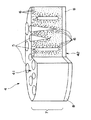
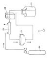
図1は、本発明の細胞支持基材の実施例の断面を示す模式図、図2は、本発明の培養装置の実施例を示す回路図である。
【0030】
図1に示すように、細胞支持基材4は、細胞を支持する細胞支持層7と、スキン層8とを有している。
【0031】
細胞支持基材4では、通過する液体は、原則として、細胞支持層7からスキン層8へ流れる。以下、細胞支持基材4において、細胞支持層7が存在する側を「上流端」といい、これに対向する面、すなわちスキン層8が存在する側を「下流端」という。
【0032】
細胞支持層7には、大きい孔径を有する複数の巨大孔5と小さい孔径を有する複数の連通孔6とが形成されている。
【0033】
巨大孔5は、例えば円柱状、円錐状等の指状構造をしており、細胞支持基材4中に分布して存在している。そして、巨大孔5の長手方向は、細胞支持基材4を通過する液が流れる方向とほぼ等しい。また、巨大孔5は、細胞支持基材4を貫通していない。
【0034】
巨大孔5は、細胞支持基材4を通過する液体の流路となる。さらには、細胞支持基材4に細胞懸濁液を流した場合には、該細胞が通過する通路になると考えられる。
【0035】
上流端41側に存在する巨大孔5の中には、上流端41の端面に開放しているものもある。この開放した巨大孔5では、上流端41の端面と巨大孔5の内面が連続している。この開放した巨大孔5により、細胞懸濁液を上流側から流した場合に、細胞支持基材4の深部にまで細胞が入りやすくなる。
【0036】
開放している巨大孔5の開口部の平均孔径は、目的細胞の大きさや種類(性質)によって異なり、特に限定されないが、細胞の充填性の観点からは、100〜2000μm 程度が好ましく、500〜1500μm 程度がより好ましい。
【0037】
巨大孔5の孔径は、上流端41から下流端42の方向に行くに従って、小さくなっていく傾向を有していることが好ましい。このような傾向を有していると、細胞支持基材4が支持する目的細胞を細胞支持層7に、より均等に分布させることが可能になる。
【0038】
巨大孔5の平均孔径は、特に限定されないが、100〜1000μm 程度が好ましく、100〜500μm 程度がより好ましい。平均孔径がこの範囲の下限値を下回ると、細胞支持基材4内を細胞懸濁液が円滑に流れなくなる、もしくは、目的細胞を深部まで導入することが困難となる場合があるからである。一方、上限値を超えると、細胞支持層7の実質的な体積が減少して、目的細胞の担持力が減少する場合があるからである。
【0039】
連通孔6は、隣接する連通孔6同士が相互に連通して、三次元的な孔の連続集合体を構成するものである。
【0040】
連通孔6は、細胞支持基材4を通過する液体の流路となると同時に、後述するような特徴により、目的細胞(支持すべき細胞)を捕捉する。
【0041】
この連通孔6は、基本的には、上流端41の端面および巨大孔5の内面(以下、これらを総称して「表面」という)から内部(奥部)に向かって、すなわち表面から離間するに従って、孔径が減少するように形成されている。
【0042】
また、連通孔6の孔径は、細胞充填時に細胞の通路として適切な程度の目的細胞の径より大きい孔径から、細胞を捕捉するのに適切な程度の目的細胞の径より小さい孔径まで分布している。
【0043】
従って、連通孔6の表面に近い部分では、細胞は通過し易く、すなわち捕捉されにくく、奥部に行くに従って捕捉され易くなる。
【0044】
但し、連通孔6の孔径が減少する度合いは、細胞支持層7の場所ごとにある程度相違していることが好ましい。これにより、目的細胞が捕捉される場所は、前記表面から一定の距離のところに集中せず、細胞支持基材4中の広い範囲に分布、特に均一に分布するようになる。このために、連通孔6が目的細胞を捕捉した後も、連通孔6を通過する液体の流路が確保され、細胞支持後も細胞支持基材4中を液体が万遍なく、かつ速やかに通過できるようになると考えられる。さらには、より多くの目的細胞を細胞支持基材4中で均一に支持すること、すなわち細胞支持基材4が目的細胞を高密度で担持することが可能となると考えられる。
【0045】
連通孔6の平均孔径は、特に限定されないが、5〜100μm であることが好ましく、10〜70μm であることがより好ましい。平均孔径がこの範囲の上限値を超えると、目的細胞の捕捉率が下がる場合があり、下限値を下回ると、目的細胞が連通孔6の奥まで入って行かない、あるいは、細胞を支持した後、通過する液体の流路を十分に確保できない場合があるからである。
【0046】
連通孔6の最大孔径は、特に限定されないが、前記と同様の理由から、30〜200μm であることが好ましく、50〜150μm であることがより好ましい。ここで、最大孔径とは、存在する全ての連通孔6のうちの最大孔径という意味ではなく、孔径分布の中から偏差5%以上のものを除外した上での最大孔径をいう。
【0047】
連通孔6の最小孔径は、特に限定されないが、前記と同様の理由から、0.1〜10μm であることが好ましく、1〜10μm であることがより好ましい。ここで、最小孔径とは、存在する全ての連通孔6のうちの最小孔径という意味ではなく、孔径分布の中から偏差5%以下のものを除外した上での最小孔径をいう。
【0048】
細胞支持層7に用いられる材質は、多孔質で、細胞を支持可能なものであればよい。細胞の捕捉され易さの観点からは、伸縮性を有するものが好ましい。また、液体を通過させる観点からは、親水性・保水性を有するものが好ましい。さらに、安定性の観点からは、支持する細胞によって代謝されにくいものが好ましい。このような材質としては、天然産生物、合成樹脂発泡体などが挙げられる。合成樹脂発泡体としては、例えば、ポリウレタン、ポリビニルアルコールなどが挙げられる。
【0049】
以上のような細胞支持層7で非常に高い細胞捕捉率が得られるが、さらにスキン層8を設けることによって、細胞支持層7で捕捉されなかった微量の細胞があったとしても、この細胞の漏出を防止することができる。
【0050】
スキン層8は、多孔質体で構成されている。このスキン層8の平均孔径は、連通孔6の平均孔径よりも小さいことが好ましい。スキン層8の平均孔径を連通孔6の平均孔径よりも小さくすると、細胞の漏出をさらに効果的に防止できるようになり、より確実に細胞支持基材4に目的細胞を支持させることが可能になる。
【0051】
スキン層8の平均孔径は、特に限定されないが、0.2〜35μm 程度であることが好ましく、1〜10μm 程度であることがより好ましく、1〜5μm 程度であることがさらに好ましい。平均孔径がこの範囲の上限値を超えると、細胞の漏出を効果的に防止できない場合があり、下限値を下回ると、通過する液体の流路を十分に確保できない場合があるからである。
【0052】
スキン層8の厚さは、特に限定されないが、10μm 〜2mm程度が好ましく、100μm 〜1mm程度がより好ましい。厚さがこの範囲の上限値を超えると、スキン層8の孔径によっては、細胞支持基材4を液体が速やかに通過しなくなる場合があり、下限値を下回ると、前記スキン層8の機能が十分に発揮されない場合があるからである。
【0053】
スキン層8には、細胞支持層7に使用可能な材質と同様のものが好適に用いられる。
【0054】
スキン層8は、細胞支持層7と一体的に形成されていてもよく、また、別部材が細胞支持層7に接合されていてもよい。
【0055】
細胞支持層7とスキン層8が一体化された細胞支持基材4は、製造が容易であり、細胞支持層7とスキン層8の接合強度を高めることができる。
【0056】
スキン層8が接合された細胞支持基材4では、孔径のコントロールが容易である。
【0057】
なお、細胞支持基材4は、細胞支持層7とスキン層8との間や、スキン層8の下流側に少なくとも1つの他の層を有してもよい。
【0058】
また、スキン層8は、細胞支持層7から分離したものとなっていてもよい。すなわち、スキン層8は、細胞支持層7の下流側で、細胞支持層7とある程度距離が離れたところに設けられていてもよい。
【0059】
さらに、細胞支持基材4は、スキン層8を有していなくともよい。
特に、支持できる細胞数を上げるために、複数の細胞支持基材4を後述する細胞支持モジュール3などに重ねて収納するような場合などには、最下流に位置する細胞支持基材4以外はスキン層を設けないことにより、上流側から下流側までの各細胞支持基材4は、より均等に目的細胞を担持できるようになる。従って、細胞支持モジュール3の担持できる細胞数を向上させることができる。
【0060】
細胞支持基材4は、円柱状である。細胞支持基材4を円柱状にすると、目的細胞を細胞支持基材4内に、より均一に担持させることが可能になる。なお、細胞支持基材4は、円柱状以外の任意の形状とすることも可能である。細胞支持モジュール3を充填する場所によっては、かかる場所に適した形状とすることにより、より好適に使用することが可能となる。
【0061】
細胞支持基材4の厚さは、特に限定されないが、0.1〜300mm程度が好ましく、0.5〜10mm程度がより好ましい。厚さが、この範囲の上限値を超えると、目的細胞の充填性が悪くなる場合があり、下限値を下回ると、目的細胞の捕捉率が低くなる場合があるからである。
【0062】
細胞支持基材4には、動物細胞、植物細胞、細菌などの細胞(遺伝子操作、細胞融合等がなされた形質転換細胞も含む)を支持させることが可能である。特に、この細胞支持基材4を用いると、従来高密度培養が困難であった動物細胞(その中でも特に、肝細胞、肺細胞、腎細胞、卵巣細胞、膵ランゲルハンス島細胞、神経細胞、下垂体細胞、甲状腺細胞、副腎皮質細胞等の臓器を構成する細胞、繊維芽細胞、上皮細胞、内皮細胞など、培養する際に被付着体が必要な付着性動物細胞)を容易に、しかも高い捕捉率で支持・培養することが可能となる。また、浮遊性細胞である造血幹細胞、ストローマ細胞等についても、従来技術より遥かに容易かつ高い捕捉率で支持・培養が可能となる。
【0063】
細胞支持基材4に目的細胞の懸濁液を通過させると、かかる液が細胞支持層7を通過する際に、目的細胞が連通孔6に捕捉され、支持される。すなわち、細胞支持基材4には、目的細胞の懸濁液を上流側から通過させるだけで、目的細胞を捕捉、担持させることができる。
【0064】
このように、細胞支持基材4を用いると、容易に細胞を担持させることができる。しかも、細胞を支持する際に特別な操作を必要としないので、短時間で細胞を支持することができる。また、短時間で大量の細胞を担持できるので充填作業の効率もよい。
【0065】
細胞支持基材4に液体を通過させる方法としては、例えば、細胞懸濁液を上流側から重力で自然流下させる方法、シリンジポンプなどの定流速ポンプ、アスピレーターなどを用いる方法が挙げられる。
【0066】
そして、このような細胞支持基材4は、例えば、培養装置、液体処理装置等に用いることができ、この場合には、細胞の培養や、細胞を用いた処理が容易に可能となる。
【0067】
以下、この細胞支持基材4を用いた培養装置1について説明する。
図2に示すように、培養装置1は、灌流系とガスを加えるガスラインとを有している。灌流系は、リザーバー21と、ポンプ22と、ガス付加装置23と、細胞支持モジュール3とを有している。ガスラインの一端はガスボンベ24に接続され、他端はガス付加装置23に接続されている。
リザーバー21は、培養装置1内を灌流する培地等の灌流液を貯留する。
【0068】
ポンプ22は、培養装置1の灌流系内で灌流液を循環させるものであり、例えばローラポンプが使用される。
【0069】
ガス付加装置23は、内部に例えば中空糸膜を有し、この膜を介してガスボンベ24から供給される酸素(または酸素を含む混合ガス)を灌流液に付与する。これにより、酸素付加された灌流液が、後述する細胞支持モジュール3中の細胞支持基材4に支持された細胞に接触し、該細胞に酸素を供給する。なお、ガスボンベ24から供給される気体は酸素に限られず、例えば、二酸化炭素、窒素、エチレン等またはこれらの混合気体など他の気体をガス付加装置23に供給してもよい。
【0070】
細胞支持モジュール3には、前述した細胞支持基材4が少なくとも1つ収納(充填)されている。この収納した細胞支持基材4中に細胞が支持されている。そして、ここで細胞は、生存、増殖、代謝・合成等の処理など種々の活動を行う。
【0071】
なお、必要に応じ、細胞支持モジュール3の内部の細胞支持基材4の下流側に、メッシュ、紙、織布、不織布、多孔質膜、多孔板、各種フィルター(例えばメンブランフィルターなど)などの濾材を設置してもよい。これにより、細胞支持モジュール3内での液流をより円滑にすることが可能となるとともに、細胞支持モジュール3の下流へ細胞が漏出するのをさらに確実に防止できる。
【0072】
そして、これらが灌流系を構成することにより、培養装置1内の密閉性が高まり、培養装置1内に雑菌等が侵入するのを防止することができる。
【0073】
以下、培養装置1の作用(使用方法)について説明する。
まず、細胞を支持した細胞支持基材4を細胞支持モジュール3に充填する。なお、充填してから、細胞支持基材4に細胞を支持させてもよい。
【0074】
次に、ポンプ22を作動させると、リザーバー21内に貯留された灌流液が、培養装置1内を灌流する。
【0075】
リザーバー21を出た灌流液は、まず、ガス付加装置23において酸素が付与される。また、このとき同時に、二酸化炭素などの灌流液中に溶解していた不要な気体が排出される。
【0076】
この酸素が付与された灌流液が細胞支持モジュール3に到達し、細胞支持基材4を通過することにより、細胞支持基材4内に担持された細胞が生命活動を行うために必要な酸素、さらには栄養素が細胞に供給される。
【0077】
その後、細胞支持モジュール3を通過した灌流液は、再びリザーバー21内に貯留される。
【0078】
このように、灌流液が細胞支持基材4を通過することにより、細胞支持基材4内に担持された細胞に酸素、栄養素等が供給され、目的細胞を培養することが可能となる。
【0079】
培養装置1は、さらに、培養中もしくは培養後に、細胞支持基材4内に担持された細胞が産生したタンパク質、糖、ホルモン、その他化学物質等の産生物を、灌流液から回収するための機構を備えていてもよい。この機構としては、例えば、灌流系の途中あるいは灌流系からの分岐路、バイパス路等に、前記産生物を吸着、濾別等により除去し得るフィルター(産生物除去手段)を設けたものや、リザーバー21内の灌流液を定期的に洗浄、濾過等の処理あるいは交換する方法などが挙げられる。
【0080】
このような機構を備えることにより、培養の継続を維持もしくは培養を促進することができる。
【0081】
また、図2に示す装置は、液体処理装置1’として使用することもできる。すなわち、細胞支持基材4で支持した細胞の代謝・合成機能を利用して、細胞支持基材4を通過する液体を処理することができる。
【0082】
例えば、細胞支持基材4に肝細胞などの臓器を構成する細胞を支持させることにより、液体処理装置1’を人工肝臓などの人工臓器として機能させることができる。
この場合、灌流液には血漿、血液等の被処理液を用いることが可能である。
【0083】
また、細胞支持基材4に固定化細胞を支持させることにより、液体処理装置1’で特定の物質を合成・分解・処理することもできる。すなわち、液体処理装置1’をバイオリアクターとして機能させることも可能である。
また、このとき、支持した細胞により処理された液体を得ることもできる。
【0084】
以上、本発明を図示の実施例に基づいて説明してきたが、本発明はこれに限定されるものではない。
【0085】
例えば、目的細胞を固定した細胞支持基材4を、静置培養に供してもよい。
さらには、目的細胞を固定した細胞支持基材4を前述以外の他の用途、例えばウイルス生産などに用いてもよい。
【0086】
【実施例】
以下、本発明を具体的実施例に基づいてさらに詳細に説明する。
【0087】
1.細胞支持基材の製造
[1.1]細胞支持基材の材料の調整。
【0088】
まず、溶剤であるN−メチル−2−ピロリドン(NMP)に、ポリウレタン(PU)を濃度が11重量%となるように加え、さらにそこに、核剤としてポリウレタン100重量部に対し30重量部となるように塩化カルシウム(CaCl2 )を加えた。
【0089】
次に、この溶液を攪拌した。攪拌速度は1000rpm 、攪拌時間は6時間、水浴温度は40℃以下であった。
【0090】
攪拌後、8時間以上静置してから、この溶液を800g計り取り、これをプラネタリーミキサーのタンクに入れた。さらにそこに、孔形成剤として前記溶液中に含まれるポリウレタンと同重量のメチルセルロース(MC)を加え、混練した。混練速度は60rpm 、湯浴温度は60℃であった。
【0091】
[1.2]細胞支持基材の製型。
混練直後の細胞支持基材の材料を、減圧条件下におき、脱泡(脱気)した。
【0092】
次に、この脱泡した細胞支持基材の材料を、不織布で作製した箱型の容器に、厚さが15mmとなるように入れ、上面を不織布でカバーした。
【0093】
次に、これを50℃の湯浴に入れ、2時間程度浸漬し、凝固させた。さらにその後、湯浴温度を室温(水浴)とし、そこで16時間以上浸漬して、凝固をさらに促進させた。
【0094】
このとき、核剤と孔形成剤が溶け出すことにより巨大孔と連通孔が形成されたと考えられる。
【0095】
[1.3]細胞支持基材の洗浄およびスライス。
前記凝固させた細胞支持基材の材料を不織布からはがし、流水下でロール絞りにて洗浄した。
【0096】
次に、これを60℃で乾燥した。
乾燥後、この材料をスライス機で横に均等に3分割することにより、巨大孔および連通孔を有し、全体としてスポンジ状の多孔質体である細胞支持層と、スキン層とを有する細胞支持基材を得た。
【0097】
2.巨大孔、連通孔、スキン層の解析
[2.1]肉眼による細胞支持基材の観察。
【0098】
前記分割により細胞支持基材が2種類(不織布に接していた面を有するものと、不織布に接していた面を有さないもの)得られたが、その中から不織布に接していた面を有する細胞支持基材を取り出し、肉眼で観察した。
【0099】
その結果、不織布に接していた面は表面が非常に密かつ平滑であり、特に肉眼で認識できる孔は発見できなかった。一方、この面と対向する面、すなわち、スライス前の材料においてカッター(刃)が入ることにより形成された面(前記材料において内部に存在していたところ)は、表面が粗く凹凸があり、肉眼で観察できるほどの孔(巨大孔)が多数、表面全体にわたって形成されていた。
【0100】
以上の結果から、不織布に接していた面にはスキン層が形成され、これに対向する面には多数の巨大孔が開放していたことが分かった。
これを確認すべく、以下の測定を行った。
【0101】
なお、以下、不織布に接していた面を「下流端」といい、これに対向する面を「上流端」という。
【0102】
[2.2]デジタルスコープによる巨大孔の解析。
前記細胞支持基材をスライス機で横方向に8分割した。
【0103】
次に、端面をデジタルスコープ(キーエンス社製「VH−6300」)で観察した。倍率は100〜500倍であった。なお、すべての断片においてランダムに5ヶ所を観察した。
【0104】
その結果、明らかに大きな孔(巨大孔)と明らかに小さな孔(連通孔)の2種類の孔が細胞支持基材に形成されていることが確認された。また、各断片の画像を比較すると、巨大孔の大きさは、上流側から下流側へ行くに従って徐々に小さくなっていることが確認された。また、巨大孔の数は、上流側から下流側へいくに従って増加していることが確認された。
【0105】
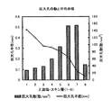
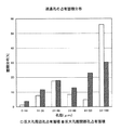
さらに、上記デジタルスコープによる観察において画像解析を行った。そして、各断片の上流側の端面1cm2 あたりに形成された巨大孔の数と巨大孔の平均半径をそれぞれ測定した。その結果を図3に示す。なお、図3中、断片の番号は、上流側から下流側へ数が大きくなるように付した。また、1〜7番目の断片は、細胞支持層を構成していた部分であり、8番目の断片は、スキン層を構成していた部分であった。
【0106】
図3の結果に示されるように、巨大孔の数は、細胞支持層においては上流側から下流側に行くに従って増加しているが、スキン層では激減していることが分かった。これにより、巨大孔は、下流端に貫通していないことが推察された。
【0107】
また、巨大孔の平均半径は、上流側から下流側へ行くに従って漸減していることが分かった。
【0108】
さらに、この細胞支持基材の上流端に開放している巨大孔の開口部の平均孔径は、952μm であった。
さらに、巨大孔の平均孔径は、530μm でった。
【0109】
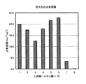
これらの結果に基づいて、各断面1cm2 あたりにおける巨大孔の占有面積を求めた。
【0110】
その結果を図4に示す。
図4の結果に示されるように、巨大孔の占有面積は、上流側から下流側の2つ手前の断片までは均等に分布していたが、スキン層の1つ手前の断片では激減し、スキン層下流側の端面ではほとんどゼロであった。従って、巨大孔は下流端に貫通していないことが確認された。
【0111】
[2.3]電子顕微鏡による連通孔の解析。
前記細胞支持基材の上流端の表面から、横方向に3分割し、その中間層を上流側の表面から、0.5mm角の大きさの立方体状の断片を切り出した。
【0112】
次に、マグネトロン・スパッタリング(日本電子社製「JUC−5000」)を用い、切り出した断片の上流側の端面に金蒸着を行った。
【0113】
そして、この金蒸着を行った端面を走査型電子顕微鏡(「日本電子社製「JSM−840」)で観察した。倍率は20〜150倍であった。
【0114】
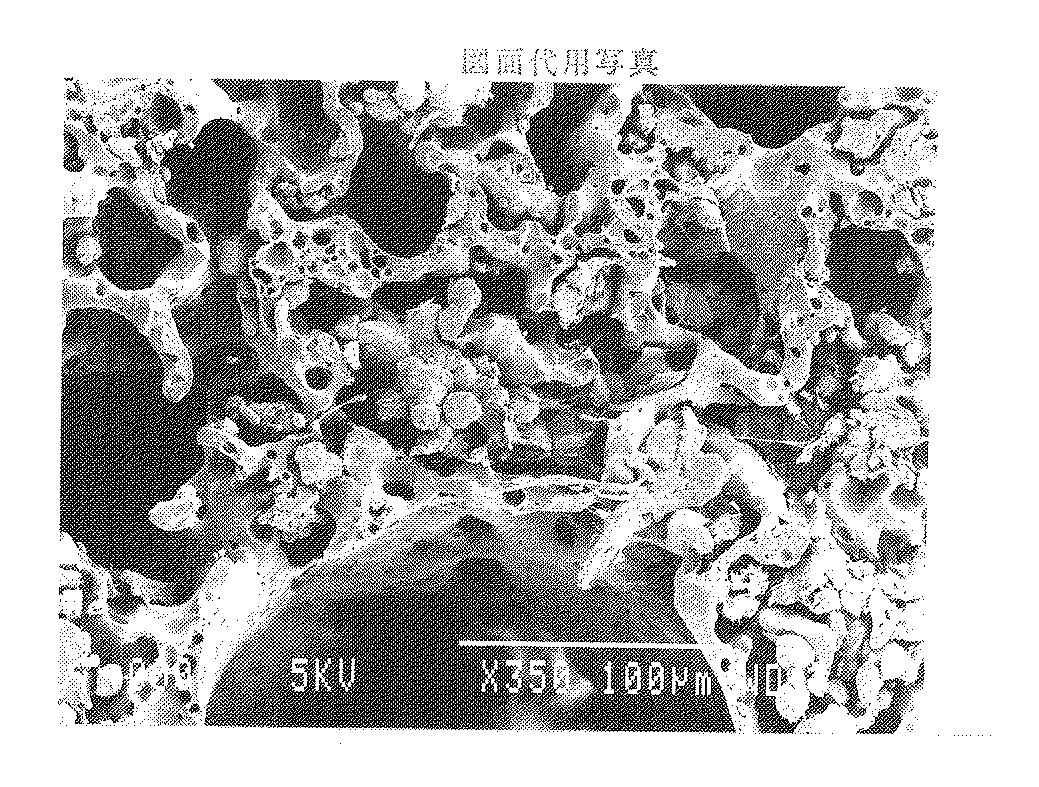
なお、得られた電子顕微鏡写真を図5に示す。図5は、細胞支持基材が横方向にスライスされた切り口の写真である。
【0115】
図5においては、写真中央の右寄りに巨大孔が形成されている。
この写真に示されるように、巨大孔の表面から、写真中の外方向に至るまで、多数の連通孔が形成されていることが確認された。しかも、巨大孔の表面から内部に行くに従って、孔が小さくなっていく、すなわち連通孔の孔径が減少していることも確認された。
【0116】
次に、この写真を前述の画像解析装置に取り込み、画像解析を行った。そして、連通孔の孔占有面積分布を測定した。
この測定は、以下のようにして行った。
【0117】
[イ]図7(図7と図5の写真は同じものである)に示す写真において、四角い枠Aの中をそれぞれサンプリングした。このサンプリングは、巨大孔周辺(巨大孔表面から0〜0.5mm程度の範囲)で4箇所行った。
【0118】
[ロ]次に、サンプリングした4箇所について、それぞれ、その中に存在する連通孔の孔径をすべて測定した。
【0119】
[ハ]次に、孔径の範囲(大きさ)ごとに連通孔の数を分類・集計した。さらにそこから、連通孔の孔径の範囲ごとに、孔占有面積を求めた。
【0120】
[ニ]さらに、4箇所の孔占有面積の値を平均して、最終的な孔占有面積の値を各孔径の範囲ごとに求めた。
【0121】
[ホ]また、図7中の巨大孔から離れた部分(巨大孔表面から0.5〜2mm程度の範囲)である四角い枠Bの中についても4箇所サンプリングし、前記と同様の測定を行い、最終的な孔占有面積の値を求めた。
【0122】
このようにして測定した巨大孔周辺および巨大孔から離れた部分の孔占有面積を図8に示す。
【0123】
図8の結果に示されるように、巨大孔周辺の連通孔では、巨大孔から離れた連通孔に比べて、孔径が大きいものが多く分布していた。すなわち、連通孔周辺では、大きい孔径の連通孔の割合が多く、巨大孔から離れたところでは、小さい孔径の連通孔の割合が増加していた。
【0124】
これにより、巨大孔の表面から内部に向かって連通孔の孔径が減少していることが確認された。
【0125】
さらには、これらの結果より、巨大孔周辺の連通孔では、大きい孔径のものが多く分布しているので、細胞が通過し易く(細胞が奥へ移行し易い)、巨大孔から離れた連通孔では、中小の孔径のものが多く分布しているので、細胞の通路(細胞を連通孔の奥まで到達させる通路)となる連通孔と細胞が捕捉される(詰まる)連通孔とがバランスよく分布していると考えられる。
【0126】
また、これらを集計した結果、連通孔の最大孔径は51〜142μm になっていることが分かった。さらに、連通孔の最小孔径は0.5〜10μm となっていることが分かった。そしてさらに、連通孔の平均孔径は20μm 前後であることが分かった。
【0127】
また、サンプリング部分を変えて同様の測定を行ったところ、値は微妙に異なったが、同様の傾向を示す結果が得られた。これにより、連通孔の孔径が減少する度合いは、細胞支持層の場所ごとにある程度相違していることが確認された。
【0128】
[2.4]電子顕微鏡によるスキン層の観察。
前記細胞支持基材の下流端、すなわちスキン層の表面を、前記と同様に電子顕微鏡で観察した。
【0129】
その結果、前記[2.3]と同じ倍率で観察したところ、スキン層に存在する孔の孔径は、連通孔の平均的な孔径よりも明らかに小さいことが確認された。
【0130】
さらに、この写真を前述の画像解析装置に取り込み、画像解析を行った。そして、スキン層の平均孔径を測定した。
その結果、平均孔径は10.55μm であった。
【0131】
3.細胞支持基材による細胞の支持
[3.1]支持する細胞の調整。
【0132】
体重180〜250gのウイスター系ラットから、コラゲナーゼ灌流法(セグレン ピー オー著、メソッズ イン セル バイオロジー(Seglen P O, Methods in Cell biology )、13巻、29頁(1976)参照)により、実質肝細胞(平均径30μm )を得た。得た肝細胞の生存率は85%以上であった。
【0133】
[3.2]培地の調整。
純水1リットルに基本培地としてウィリアムズE培地(ギブコ・ビー・アール・エル(GIBCO BRL)社製)を10gを溶解させ、さらにそこに以下の物質を、以下の濃度で添加することにより液体培地を調整した。
【0134】
インスリン :10μg/ml
エプターマルグロースファクター(EGF):50ng/ml
プロラクチン :20mU/ml
リノレン酸 :5μg/ml
CuSO4・5H2O :0.1μM
H2SeO3 :3nM
ZnSO4・7H2O :50pM
ペニシリンG :100unit/ml
ストレプトマイシン :100μg/ml
【0135】
[3.3]細胞支持基材の準備。
前記[1.細胞支持基材の製造]と同様にして製造した細胞支持基材の材料を、直径30mm、厚さ5.7mmの円盤上(容積4cm3 )に切り抜いて、細胞支持基材を得た。この細胞支持基材の一方の面は、不織布に接していた部分であり、厚さ0.9mm のスキン層を有しているものであった。
【0136】
次に、この細胞支持基材を、外周面からの液漏れがないように平膜固定用の容器に装填し、前記[3.2]で調整した培地で湿潤させた。
【0137】
[3.4]細胞支持基材の細胞捕捉率の測定。
前記細胞支持基材を装填した平膜固定用の容器に50mlリザーバーを取り付け、前記[3.1]で調整した肝細胞の懸濁液(細胞密度1.0×10⁶ cells/ml)を40ml、自然流下で流し、細胞支持基材に肝細胞を充填、支持させた(充填細胞数4.0×107 cells(細胞支持基材1cm3 あたり1.0×10⁷ cells))。充填に要した時間は、3分であった。
【0138】
次に、前記[3.2]で調整した培地を6ml/minの流速で10分間流し、漏出した細胞数を測定した。この測定は光学顕微鏡による顕微観察により行った。そして、この測定値から細胞漏出率と細胞捕捉率を求めた。
【0139】
また、充填細胞数を1.2×10⁸cells(細胞支持基材1cm3 あたり3.0×10⁷cells)にして同様の測定を行った。
【0140】
さらに、充填細胞数を2.0×10⁸cells(細胞支持基材1cm3 あたり5.0×10⁷cells)にして同様の測定を行った。
これらの結果を下記表1、表2に示す。
【0141】
【表1】
【表2】
表1、表2の結果に示されるように、本発明の細胞支持基材は、非常に多量の細胞を支持することができ(高い密度で細胞を支持できる)、さらに、高い細胞捕捉率を有していることが確認された。
【0144】
[3.5]細胞支持状態の確認。
前記[3.4]により肝細胞を支持した細胞支持基材を前記スライス機で縦方向に均等に3分割したものおよび横方向に均等に3分割したものを作製し、それらの各断面を前記と同様に電子顕微鏡で観察した。各所で撮影した写真のうちの一枚を図6に示す。なお、倍率は350倍であった。
【0145】
これらの結果から、肝細胞は一箇所に集中することなく、全体にわたってまんべんなく存在していた。これにより、目的細胞が捕捉される場所は、細胞支持基材中の一定の場所に集中しているわけではなく、広い範囲に分布していることが確認された。
【0146】
4.培養装置
[4.1]肝細胞の培養。
【0147】
前記[3.細胞支持基材による細胞の支持]と同様にして、最終細胞充填密度が1×10⁷cells/cm3となるように肝細胞を細胞支持基材に充填、支持させた。
これを図2に示す構成の培養装置にて培養した。
【0148】
灌流液には前記[3.2]で調整した培地と同様のものを50ml用い、流速6ml/minで灌流させた。また、灌流液に酸素を付与するため、酸素(O2 )95%、二酸化炭素(CO2 )5%の混合ガスを流速200ml/minでガス付加装置に流した。使用したガス付加装置の中空糸膜の膜面積は、0.03m2であった。
【0149】
培地は、12時間ごとに半量ずつ交換した。
その結果、5日後でも肝細胞は生存し、活動していることが確認された。これにより、本発明の細胞支持基材を用いた培養装置を用いると、従来は培養が困難であった付着性動物細胞ですら十分に培養できることが確認された。
【0150】
[4.2]培養装置における肝細胞の固定化率。
前記[3.細胞支持基材による細胞の支持]と同様にして、最終細胞充填密度が1×10⁷cells/cm3となるように肝細胞を細胞支持基材に充填、支持させた。これを前記[4.1]と同様の培養装置に充填した。
【0151】
そして、流速5ml/minで24時間、前記[4.1]と同様にして灌流液を灌流させた。なお、灌流液には前記[3.2]で調整した培地と同様のものを50ml用いた。
【0152】
そして、灌流後の培地について、前記[3.4]と同様の測定を行うことにより、この培養装置を稼働させた後の細胞の固定化率を求めた。
【0153】
その結果、固定化率は99.9%以上であり、非常に優れた固定化率を有していることが確認された。
【0154】
5.人工肝臓
さらに、前記[4.1]と同様の装置を人工肝臓としても機能させた。
【0155】
灌流液には、前記[3.2]で調整した培地を用いた。また、灌流液は、12時間ごとに半量ずつ交換した。
【0156】
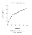
この装置の人工肝臓としての能力を調べるため、ELISA法(酵素抗体法)にて交換した前記培地中のアルブミンの濃度を測定し、肝細胞が合成したアルブミンの量を調べた。
【0157】
この測定結果に基づき求められた肝細胞を支持した細胞支持基材1cm3 あたり(肝細胞1×10⁷cellsあたり)のアルブミン合成量の経時的変化を図9に示す。
【0158】
図9に示すように、処理開始後5日間、細胞支持基材により支持された肝細胞がアルブミンを合成したことが確認された。
これにより、この装置は人工肝臓として機能することが確認された。
【0159】
なお、人工肝臓として用いた当該装置について、前記[4.2]の結果を考慮すると、前記と同様の非常に高い固定化率を有することが推測される。
【0160】
【発明の効果】
以上述べたように、本発明によれば、簡単な操作で、しかも短時間に細胞を支持することができる。
【0161】
さらには、高い捕捉率、固定化率で目的細胞を支持することができる。
また、細胞支持基材内部に均一に、しかも高密度で細胞を支持することが可能になる。
【0162】
また、通常の細胞はもとより、従来は培養が困難であった付着性動物細胞も培養することができる等、その適用範囲や応用分野が広い。
【0163】
以上より、培養装置や人工臓器のような液体処理装置への適用が可能であり、特に、高性能、高効率で、安全性の高い培養装置や液体処理装置を提供することが可能になる。
【図面の簡単な説明】
【図1】本発明の細胞支持基材の実施例の断面を示す模式図である。
【図2】本発明の培養装置の実施例を示す回路図である。
【図3】本発明の実施例における細胞支持基材の各断片の上流側端面上に存在する巨大孔の数と巨大孔の平均半径とを示すグラフである。
【図4】図3と同一の各断片の上流側端面上に存在する巨大孔の占有面積を示すグラフである。
【図5】顕微鏡写真である。
【図6】顕微鏡写真である。
【図7】図5の写真におけるサンプリング領域を示す図である。
【図8】本発明の実施例における細胞支持基材において巨大孔周辺および巨大孔から離れた部分の孔径ごとの孔占有面積を表したグラフである。
【図9】本発明の実施例における人工肝臓においてアルブミン合成量の経時的変化を表したグラフである。
【符号の説明】
1 培養装置
1’ 液体処理装置
21 リザーバー
22 ポンプ
23 ガス付加装置
24 ガスボンベ
3 細胞支持モジュール
4 細胞支持基材
41 上流端
42 下流端
5 巨大孔
6 連通孔
7 細胞支持層
8 スキン層[0001]
BACKGROUND OF THE INVENTION
The present invention relates to a cell support substrate that supports cells, a culture apparatus using the cell support substrate, and a liquid treatment apparatus.
[0002]
[Prior art]
Conventionally, a microcarrier method, a holofiber method, a porous carrier method, a microcapsule method and the like are known as methods for culturing cells.
[0003]
Among these, a method of immobilizing and culturing cells by injecting or impregnating a cell suspension into a carrier having a three-dimensional porous structure has attracted attention.
[0004]
In order to perform perfusion culture using the cell support carrier, it is necessary to secure a flow path for the liquid medium. For this reason, a medium channel narrow tube having a diameter of 1.5 mm is opened on the carrier at a pitch of 3 mm (Ijima et al., Artificial Organ 23, 463 (1994)), or the carrier is made into a 2 mm square block (Oshima et al.
1169 (1997)).
[0005]
However, when cell seeding by natural sedimentation by gravity is performed using these methods, the cell immobilization rate is as extremely low as 10 to 30%. Therefore, these methods cannot immobilize cells efficiently and are not practical.
[0006]
In addition, a device has been devised to increase the cell immobilization rate by applying acceleration by centrifugation to the carrier after cell filling to move the cells outward in the carrier. In this method, the immobilization rate is increased to 80%.
[0007]
However, this method is not practical because it takes a long time to immobilize cells and the operation becomes complicated.
[0008]
Therefore, there is currently no technology that can fix and culture cells easily, efficiently in a short time, and at a high density.
[0009]
[Problems to be solved by the invention]
An object of the present invention is to provide a cell support substrate capable of supporting cells efficiently in a short time and at a high density, a culture apparatus using the cell support substrate, and a liquid treatment apparatus. .
[0010]
[Means for Solving the Problems]
The purpose of this is as follows (1) to(10)This is achieved by the present invention.
[0011]
(1)In the thickness direction,CellsCapture the cells when the containing liquid is passed through,To supportHas cell support layerA cell support substrate,
The cell support layer has an average pore size of 100 to 1000 μm.Multiple giant holesAnd a plurality of communication holes having an average pore diameter of 5 to 100 μm,
The plurality of communication holes are configured such that the hole diameter decreases as the distance from the upstream end of the cell support layer through which the liquid passes and the inner surface of the giant hole is increased.A cell-supporting base material formed.
[0012]
(2) The hole diameter of the communication hole isThe cellThe cell-supporting substrate according to (1), wherein the cell-supporting substrate is distributed from a larger pore diameter to a smaller pore diameter.
[0013]
(3)In the thickness direction,CellsCapture the cells when the containing liquid is passed through,To supportHas cell support layerA cell support substrate,
The cell support layer has an average pore size of 100 to 1000 μm.Multiple giant holesAnd a plurality of communication holes having an average pore diameter of 5 to 100 μm,
The hole diameter of the communication hole isThe abovePore size larger than cell sizeTo small pore sizesA cell-supporting substrate characterized by being distributed.
[0014]
(4) The giant hole, Upstream end of the cell support layerThe cell-supporting substrate according to any one of the above (1) to (3), wherein the cell-supporting substrate includes those that are open.
[0015]
(5) The giant hole,The cell-supporting substrate according to any one of the above (1) to (4), which has a finger-like structure.
[0016]
(6)The cell support substrate according to any one of the above (1) to (5), which has a porous skin layer having an average pore size smaller than the average pore size of the communication pores on the downstream side of the cell support layer.
[0017]
(7)The cell support according to any one of (1) to (6), wherein the plurality of communication holes are configured such that adjacent communication holes communicate with each other to form a three-dimensional continuous assembly of holes. Base material.
[0018]
(8)The cell support layer isThe cell-supporting substrate according to any one of (1) to (7), which has stretchability.
[0019]
(9) having the cell-supporting substrate according to any one of (1) to (8) above,
With the cell support substrateThe cellA culture apparatus characterized by supporting and culturing.
[0020]
(10)(1) to (8) aboveHaving a cell-supporting substrate according to any one of
Liquid was passed through the cell support substrate and supported by the cell support substrate.AboveA liquid processing apparatus, wherein the liquid is processed by a cell metabolism / synthesis function.
[0028]
DETAILED DESCRIPTION OF THE INVENTION
The present invention will be described below based on preferred embodiments shown in the accompanying drawings.
[0029]
FIG. 1 is a schematic diagram showing a cross-section of an embodiment of the cell-supporting substrate of the present invention, and FIG.
[0030]
As shown in FIG. 1, the
[0031]
In the
[0032]
The
[0033]
The giant holes 5 have a finger-like structure such as a columnar shape or a conical shape, and are distributed in the
[0034]
The
[0035]
Some of the
[0036]
The average pore size of the opening of the open
[0037]
It is preferable that the hole diameter of the
[0038]
The average pore diameter of the
[0039]
The
[0040]
The
[0041]
The
[0042]
Further, the pore diameter of the
[0043]
Therefore, in the portion close to the surface of the
[0044]
However, the degree to which the hole diameter of the
[0045]
The average pore diameter of the communication holes 6 is not particularly limited, but is preferably 5 to 100 μm, and more preferably 10 to 70 μm. If the average pore diameter exceeds the upper limit of this range, the capture rate of the target cells may be reduced. If the average pore diameter is lower than the lower limit, the target cells do not enter the back of the
[0046]
Although the maximum hole diameter of the
[0047]
The minimum hole diameter of the
[0048]
The material used for the
[0049]
Although a very high cell capture rate can be obtained with the
[0050]
The
[0051]
The average pore diameter of the
[0052]
The thickness of the
[0053]
The
[0054]
The
[0055]
The
[0056]
In the
[0057]
The
[0058]
The
[0059]
Furthermore, the
In particular, in order to increase the number of cells that can be supported, a plurality of
[0060]
The
[0061]
Although the thickness of the cell
[0062]
The
[0063]
When the suspension of target cells is passed through the
[0064]
Thus, when the
[0065]
Examples of the method of allowing the liquid to pass through the
[0066]
And such a cell
[0067]
Hereinafter, the
As shown in FIG. 2, the
The
[0068]
The
[0069]
The
[0070]
The
[0071]
If necessary, a filter medium such as mesh, paper, woven fabric, non-woven fabric, porous membrane, porous plate, various filters (for example, a membrane filter) is provided downstream of the
[0072]
And when these comprise a perfusion system, the airtightness in the
[0073]
Hereinafter, an operation (usage method) of the
First, the
[0074]
Next, when the
[0075]
The perfusate exiting the
[0076]
When the perfusate to which oxygen is applied reaches the
[0077]
Thereafter, the perfusate that has passed through the
[0078]
Thus, when the perfusate passes through the
[0079]
The
[0080]
By providing such a mechanism, the continuation of the culture can be maintained or the culture can be promoted.
[0081]
Also, the apparatus shown in FIG. 2 can be used as the
[0082]
For example, the
In this case, a liquid to be treated such as plasma and blood can be used as the perfusate.
[0083]
In addition, a specific substance can be synthesized / decomposed / processed by the
At this time, a liquid treated with the supported cells can also be obtained.
[0084]
Although the present invention has been described based on the illustrated embodiment, the present invention is not limited to this.
[0085]
For example, the
Furthermore, you may use the cell
[0086]
【Example】
Hereinafter, the present invention will be described in more detail based on specific examples.
[0087]
1. Cell support substrate production
[1.1] Preparation of material for cell support substrate.
[0088]
First, polyurethane (PU) is added to N-methyl-2-pyrrolidone (NMP), which is a solvent, so as to have a concentration of 11% by weight, and 30 parts by weight with respect to 100 parts by weight of polyurethane as a nucleating agent. Calcium chloride (CaCl2 ) Was added.
[0089]
The solution was then stirred. The stirring speed was 1000 rpm, the stirring time was 6 hours, and the water bath temperature was 40 ° C. or lower.
[0090]
After stirring, the mixture was allowed to stand for 8 hours or more, and 800 g of this solution was weighed and placed in a tank of a planetary mixer. Further, methylcellulose (MC) having the same weight as the polyurethane contained in the solution was added as a pore-forming agent and kneaded. The kneading speed was 60 rpm, and the hot water bath temperature was 60 ° C.
[0091]
[1.2] Molding of cell support substrate.
The cell support base material immediately after kneading was placed under reduced pressure conditions and degassed (degassed).
[0092]
Next, the defoamed cell support base material was put into a box-shaped container made of a nonwoven fabric so that the thickness was 15 mm, and the upper surface was covered with the nonwoven fabric.
[0093]
Next, this was placed in a 50 ° C. hot water bath and immersed for about 2 hours to solidify. Thereafter, the hot water bath temperature was set to room temperature (water bath), where it was immersed for 16 hours or more to further promote solidification.
[0094]
At this time, it is considered that the nucleating agent and the pore-forming agent were dissolved to form a giant hole and a communicating hole.
[0095]
[1.3] Wash and slice cell support substrate.
The coagulated cell support base material was peeled off from the nonwoven fabric and washed with a roll squeeze under running water.
[0096]
Next, this was dried at 60 ° C.
After drying, this material is equally divided into three horizontally by a slicing machine, thereby having a cell support layer having a large pore and a communication hole, which is a sponge-like porous body as a whole, and a skin layer. A substrate was obtained.
[0097]
2. Analysis of giant holes, communication holes and skin layers
[2.1] Observation of cell-supporting substrate with the naked eye.
[0098]
Two types of cell-supporting substrates (one having a surface in contact with the non-woven fabric and one having no surface in contact with the non-woven fabric) were obtained by the above-mentioned division, and the surface having the surface in contact with the non-woven fabric was among them. The cell support substrate was removed and observed with the naked eye.
[0099]
As a result, the surface that was in contact with the nonwoven fabric was very dense and smooth, and no holes that could be recognized with the naked eye were found. On the other hand, the surface facing this surface, that is, the surface formed by the insertion of the cutter (blade) in the material before slicing (where it was present in the material) is rough and uneven, Many pores (giant pores) that can be observed in FIG. 1 were formed over the entire surface.
[0100]
From the above results, it was found that a skin layer was formed on the surface that was in contact with the nonwoven fabric, and a large number of large holes were opened on the surface facing the skin layer.
In order to confirm this, the following measurements were performed.
[0101]
Hereinafter, the surface in contact with the nonwoven fabric is referred to as “downstream end”, and the surface facing this is referred to as “upstream end”.
[0102]
[2.2] Analysis of giant holes using a digital scope.
The cell support substrate was divided into 8 in the transverse direction by a slicing machine.
[0103]
Next, the end surface was observed with a digital scope (“VH-6300” manufactured by Keyence Corporation). The magnification was 100 to 500 times. In all the fragments, 5 spots were observed at random.
[0104]
As a result, it was confirmed that two types of pores, apparently large pores (giant pores) and clearly small pores (communication pores), were formed in the cell support substrate. Further, comparing the images of each fragment, it was confirmed that the size of the giant hole gradually decreased from the upstream side to the downstream side. In addition, it was confirmed that the number of giant holes increased from upstream to downstream.
[0105]
Furthermore, image analysis was performed in the observation using the digital scope. And the end face 1cm upstream of each piece2 The number of giant holes formed around and the average radius of the giant holes were measured. The result is shown in FIG. In FIG. 3, the fragment numbers are assigned so that the number increases from the upstream side to the downstream side. The 1st to 7th fragments were portions constituting the cell support layer, and the 8th fragment was a portion constituting the skin layer.
[0106]
As shown in the results of FIG. 3, it was found that the number of macropores increased from the upstream side to the downstream side in the cell support layer, but decreased drastically in the skin layer. Thereby, it was guessed that the huge hole did not penetrate to the downstream end.
[0107]
Moreover, it turned out that the average radius of a huge hole is decreasing gradually as it goes downstream from an upstream.
[0108]
Further, the average pore diameter of the opening of the giant pore opened at the upstream end of the cell supporting substrate was 952 μm.
Furthermore, the average pore diameter of the giant pores was 530 μm.
[0109]
Based on these results, each cross-section 1cm2 The area occupied by the giant holes in the perimeter was obtained.
[0110]
The result is shown in FIG.
As shown in the results of FIG. 4, the occupied area of the giant pores was evenly distributed from the upstream side to the two previous fragments on the downstream side, but drastically decreased in the fragment immediately before the skin layer, The end face on the downstream side of the skin layer was almost zero. Therefore, it was confirmed that the giant hole did not penetrate the downstream end.
[0111]
[2.3] Analysis of communication hole by electron microscope.
From the surface of the upstream end of the cell support substrate, it was divided into three in the lateral direction, and the intermediate layer was cut out from the upstream surface to form a 0.5 mm square cubic piece.
[0112]
Next, using magnetron sputtering (“JUC-5000” manufactured by JEOL Ltd.), gold deposition was performed on the upstream end face of the cut piece.
[0113]
And the end surface which performed this gold vapor deposition was observed with the scanning electron microscope ("JSM-840" by JEOL Ltd.). The magnification was 20 to 150 times.
[0114]
In addition, the obtained electron micrograph is shown in FIG. FIG. 5 is a photograph of a cut surface obtained by slicing the cell support substrate in the lateral direction.
[0115]
In FIG. 5, a huge hole is formed on the right side of the center of the photograph.
As shown in this photograph, it was confirmed that a large number of communication holes were formed from the surface of the huge hole to the outside in the photograph. Moreover, it has been confirmed that the holes become smaller as they go from the surface of the giant hole to the inside, that is, the diameter of the communication hole is reduced.
[0116]
Next, this photograph was taken into the above-described image analysis apparatus and image analysis was performed. And the hole occupation area distribution of the communicating hole was measured.
This measurement was performed as follows.
[0117]
[A] In the photograph shown in FIG. 7 (the photographs in FIGS. 7 and 5 are the same), the inside of the square frame A was sampled. This sampling was performed at four locations around the large hole (a range of about 0 to 0.5 mm from the surface of the large hole).
[0118]
[B] Next, all of the diameters of the communication holes existing in the four sampled locations were measured.
[0119]
[C] Next, the number of communication holes was classified and tabulated for each range (size) of hole diameter. Furthermore, the hole occupation area was calculated | required for every range of the hole diameter of a communicating hole from there.
[0120]
[D] Further, the values of the four hole occupation areas were averaged, and the final value of the hole occupation area was determined for each hole diameter range.
[0121]
[E] In addition, four points were sampled in the square frame B which is a part away from the giant hole in FIG. 7 (a range of about 0.5 to 2 mm from the giant hole surface), and the same measurement as above was performed Then, the final hole occupation area value was determined.
[0122]
FIG. 8 shows the hole occupying area around the giant hole and the part away from the giant hole measured in this way.
[0123]
As shown in the results of FIG. 8, in the communication holes around the large holes, many holes having a large hole diameter were distributed compared to the communication holes apart from the large holes. That is, in the periphery of the communication hole, the ratio of communication holes having a large hole diameter is large, and the ratio of communication holes having a small hole diameter is increased away from the giant hole.
[0124]
Thereby, it was confirmed that the hole diameter of the communicating hole is decreasing from the surface of the giant hole to the inside.
[0125]
Furthermore, from these results, the communication holes around the large hole have many large pore diameters distributed, so that cells can easily pass through (cells can easily move to the back), and the communication holes separated from the large hole. Since there are many small and medium pore diameter distributions, there is a balanced distribution of communication holes that serve as cell passages (passages that allow cells to reach the back of the communication holes) and communication holes that capture (clog) cells. it seems to do.
[0126]
Moreover, as a result of totaling these, it was found that the maximum hole diameter of the communication holes was 51 to 142 μm. Furthermore, it was found that the minimum hole diameter of the communication hole was 0.5 to 10 μm. Furthermore, it was found that the average hole diameter of the communication holes was around 20 μm.
[0127]
Moreover, when the same measurement was performed by changing the sampling part, the value was slightly different, but the result showing the same tendency was obtained. Thereby, it was confirmed that the degree to which the hole diameter of the communication hole decreases is somewhat different for each location of the cell support layer.
[0128]
[2.4] Observation of skin layer by electron microscope.
The downstream end of the cell supporting substrate, that is, the surface of the skin layer was observed with an electron microscope in the same manner as described above.
[0129]
As a result, when observed at the same magnification as [2.3], it was confirmed that the pore diameter of the pores existing in the skin layer was clearly smaller than the average pore diameter of the communication holes.
[0130]
Furthermore, this photograph was taken into the above-mentioned image analysis apparatus and image analysis was performed. And the average hole diameter of the skin layer was measured.
As a result, the average pore diameter was 10.55 μm.
[0131]
3. Cell support by cell support substrate
[3.1] Preparation of supporting cells.
[0132]
Parenchymal hepatocytes (see Seglen PO, Methods in Cell biology, Vol. 13, p. 29 (1976)) from Wistar rats weighing 180-250 g by collagenase perfusion (Seglen PO, Methods in Cell biology), Vol. An average diameter of 30 μm) was obtained. The survival rate of the obtained hepatocytes was 85% or more.
[0133]
[3.2] Preparation of medium.
Dissolve 10 g of Williams E medium (GIBCO BRL) as a basic medium in 1 liter of pure water, and add the following substances to the liquid medium at the following concentrations. Adjusted.
[0134]
Insulin: 10 μg / ml
Eptermal Growth Factor (EGF): 50ng / ml
Prolactin: 20mU / ml
Linolenic acid: 5μg / ml
CuSOFour・ 5H2O: 0.1 μM
H2SeOThree : 3nM
ZnSOFour・ 7H2O: 50 pM
Penicillin G: 100unit / ml
Streptomycin: 100 μg / ml
[0135]
[3.3] Preparation of cell support substrate.
[1. The material of the cell support base material manufactured in the same manner as in [Manufacture of cell support base material] on a disc having a diameter of 30 mm and a thickness of 5.7 mm (volume: 4 cm)Three ) To obtain a cell supporting substrate. One surface of this cell-supporting base material was a portion in contact with the nonwoven fabric and had a skin layer having a thickness of 0.9 mm.
[0136]
Next, this cell-supporting substrate was loaded into a flat membrane-fixing container so as not to leak from the outer peripheral surface, and was wetted with the medium prepared in the above [3.2].
[0137]
[3.4] Measurement of cell capture rate of cell support substrate.
A 50 ml reservoir was attached to the flat membrane-fixing container loaded with the cell support substrate, and the hepatocyte suspension prepared in [3.1] (cell density 1.0 × 10 66 cells / ml) was allowed to flow under natural flow, and the cell support substrate was filled with hepatocytes and supported (number of packed cells: 4.0 × 10⁷ cells (cell support substrate 1cmThree Per 1.0 × 10⁷ cells)). The time required for filling was 3 minutes.
[0138]
Next, the medium prepared in [3.2] was flowed at a flow rate of 6 ml / min for 10 minutes, and the number of leaked cells was measured. This measurement was performed by microscopic observation with an optical microscope. Then, the cell leakage rate and the cell capture rate were determined from the measured values.
[0139]
In addition, the number of packed cells is 1.2 × 10⁸cells (cell support substrate 1cmThree 3.0 × 10 per7cells) and the same measurement was performed.
[0140]
Furthermore, the number of packed cells is 2.0 × 10⁸cells (cell support substrate 1cmThree Per 5.0 × 10⁷cells) and the same measurement was performed.
These results are shown in Tables 1 and 2 below.
[0141]
[Table 1]
[Table 2]
As shown in the results of Tables 1 and 2, the cell support substrate of the present invention can support a very large amount of cells (can support cells at a high density), and has a high cell capture rate. It was confirmed to have.
[0144]
[3.5] Confirmation of cell support state.
The cell support base material supporting the hepatocytes according to [3.4] above was prepared by equally slicing the cell support substrate in the longitudinal direction into three parts and in the lateral direction equally dividing into three parts. In the same manner as above, it was observed with an electron microscope. One of the photographs taken at various places is shown in FIG. The magnification was 350 times.
[0145]
From these results, hepatocytes were present uniformly throughout without being concentrated in one place. As a result, it was confirmed that the places where the target cells were captured were not concentrated in a certain place in the cell support substrate but distributed over a wide range.
[0146]
4). Incubator
[4.1] Culture of hepatocytes.
[0147]
[3. In the same manner as in [Supporting Cells by Cell Support Substrate], the final cell packing density is 1 × 10⁷cells / cmThreeThus, hepatocytes were filled and supported on a cell support substrate.
This was cultured in a culture apparatus having the configuration shown in FIG.
[0148]
As the perfusate, 50 ml of the same medium as prepared in [3.2] was used, and the perfusate was perfused at a flow rate of 6 ml / min. In order to give oxygen to the perfusate, oxygen (O2 ) 95%, carbon dioxide (CO2 ) 5% mixed gas was flowed through the gas addition device at a flow rate of 200 ml / min. The membrane area of the hollow fiber membrane of the gas addition device used was 0.03m2Met.
[0149]
The medium was changed by half every 12 hours.
As a result, it was confirmed that hepatocytes survived and were active even after 5 days. Thus, it was confirmed that even the adherent animal cells, which were conventionally difficult to culture, can be sufficiently cultured by using the culture apparatus using the cell-supporting substrate of the present invention.
[0150]
[4.2] Immobilization rate of hepatocytes in the culture apparatus.
[3. In the same manner as in [Supporting Cells by Cell Support Substrate], the final cell packing density is 1 × 10⁷cells / cmThreeThus, hepatocytes were filled and supported on a cell support substrate. This was filled into a culture apparatus similar to [4.1] above.
[0151]
Then, the perfusate was perfused in the same manner as in [4.1] at a flow rate of 5 ml / min for 24 hours. As the perfusate, 50 ml of the same medium as prepared in [3.2] was used.
[0152]
And about the culture medium after perfusion, the immobilization rate of the cell after operating this culture apparatus was calculated | required by performing the same measurement as said [3.4].
[0153]
As a result, the immobilization rate was 99.9% or more, and it was confirmed that the immobilization rate was excellent.
[0154]
5). Artificial liver
Furthermore, the same device as [4.1] was made to function as an artificial liver.
[0155]
As the perfusate, the medium prepared in [3.2] was used. The perfusate was exchanged by half every 12 hours.
[0156]
In order to examine the ability of this apparatus as an artificial liver, the concentration of albumin in the medium exchanged by ELISA (enzyme antibody method) was measured, and the amount of albumin synthesized by hepatocytes was examined.
[0157]
[0158]
As shown in FIG. 9, it was confirmed that hepatocytes supported by the cell support base material synthesized albumin for 5 days after the start of the treatment.
This confirmed that this device functions as an artificial liver.
[0159]
In addition, when the result of said [4.2] is considered about the said apparatus used as an artificial liver, it is estimated that it has the very high immobilization rate similar to the above.
[0160]
【The invention's effect】
As described above, according to the present invention, cells can be supported in a short time with a simple operation.
[0161]
Furthermore, the target cells can be supported with a high capture rate and immobilization rate.
In addition, it becomes possible to support cells uniformly and at a high density inside the cell support substrate.
[0162]
Moreover, not only normal cells but also adherent animal cells that have been difficult to cultivate in the past can be cultured.
[0163]
As described above, the present invention can be applied to a liquid treatment apparatus such as a culture apparatus or an artificial organ. In particular, it is possible to provide a culture apparatus or liquid treatment apparatus with high performance, high efficiency, and high safety.
[Brief description of the drawings]
FIG. 1 is a schematic view showing a cross section of an example of a cell-supporting substrate of the present invention.
FIG. 2 is a circuit diagram showing an embodiment of the culture apparatus of the present invention.
FIG. 3 is a graph showing the number of macropores and the average radius of macropores existing on the upstream end face of each piece of the cell-supporting substrate in an example of the present invention.
4 is a graph showing the occupied area of the giant holes existing on the upstream end face of each of the same pieces as in FIG. 3;
FIG. 5 is a photomicrograph.
FIG. 6 is a photomicrograph.
7 is a diagram showing a sampling area in the photograph of FIG. 5. FIG.
FIG. 8 is a graph showing the hole occupying area for each hole diameter in the periphery of the macropore and in the portion away from the macropore in the cell support substrate in the example of the present invention.
FIG. 9 is a graph showing changes over time in the amount of albumin synthesized in the artificial liver according to the example of the present invention.
[Explanation of symbols]
1 Incubator
1 'Liquid processing equipment
21 Reservoir
22 Pump
23 Gas addition equipment
24 gas cylinder
3 Cell support module
4 Cell support substrate
41 Upstream end
42 Downstream end
5 Giant hole
6 communication hole
7 Cell support layer
8 Skin layer
Claims (10)
前記細胞支持層は、平均孔径が100〜1000μmの複数の巨大孔と、平均孔径が5〜100μmの複数の連通孔とを備え、
前記複数の連通孔は、前記細胞支持層の前記液体を通過させる際の上流端および前記巨大孔の内面から離間するに従って、孔径が減少するように形成されていることを特徴とする細胞支持基材。 A cell-supporting substrate having a cell-supporting layer that captures and supports the cells when a cell- containing liquid is passed in the thickness direction ;
The cell support layer includes a plurality of giant pores having an average pore diameter of 100 to 1000 μm and a plurality of communication holes having an average pore diameter of 5 to 100 μm ,
The cell support base, wherein the plurality of communication holes are formed such that the pore diameter decreases as the distance from the upstream end of the cell support layer when the liquid passes through and the inner surface of the giant pore is increased. Wood.
前記細胞支持層は、平均孔径が100〜1000μmの複数の巨大孔と、平均孔径が5〜100μmの複数の連通孔とを備え、
前記連通孔の孔径は、前記細胞の径より大きい孔径から小さい孔径まで分布していることを特徴とする細胞支持基材。 A cell-supporting substrate having a cell-supporting layer that captures and supports the cells when a cell- containing liquid is passed in the thickness direction ;
The cell support layer includes a plurality of giant pores having an average pore diameter of 100 to 1000 μm and a plurality of communication holes having an average pore diameter of 5 to 100 μm ,
The cell support base material , wherein the pore diameter of the communication hole is distributed from a larger pore diameter to a smaller pore diameter .
該細胞支持基材で前記細胞を支持し、培養することを特徴とする培養装置。The cell-supporting substrate according to any one of claims 1 to 8,
A culture apparatus characterized by supporting and culturing the cells with the cell support substrate.
該細胞支持基材に液体を通過させ、該細胞支持基材で支持した前記細胞の代謝・合成機能により前記液体を処理することを特徴とする液体処理装置。The cell-supporting substrate according to any one of claims 1 to 8 ,
It is passed through the liquid to the cells supporting substrate, a liquid processing apparatus, which comprises treating the liquid by metabolic and synthesis function of the cells supported by the cell supporting substrate.
Priority Applications (4)
| Application Number | Priority Date | Filing Date | Title |
|---|---|---|---|
| JP19239098A JP4222658B2 (en) | 1998-06-23 | 1998-06-23 | Cell support substrate, culture apparatus and liquid processing apparatus |
| EP99401562A EP0967273B1 (en) | 1998-06-23 | 1999-06-23 | Cell supporting matrix, cell culture device, and fluid treating device |
| US09/338,382 US6303375B1 (en) | 1998-06-23 | 1999-06-23 | Cell supporting matrix, cell culture device, and fluid treating device |
| DE69928997T DE69928997T2 (en) | 1998-06-23 | 1999-06-23 | Cell carrier matrix, device for cell cultures and liquid treatment |
Applications Claiming Priority (1)
| Application Number | Priority Date | Filing Date | Title |
|---|---|---|---|
| JP19239098A JP4222658B2 (en) | 1998-06-23 | 1998-06-23 | Cell support substrate, culture apparatus and liquid processing apparatus |
Publications (3)
| Publication Number | Publication Date |
|---|---|
| JP2000004870A JP2000004870A (en) | 2000-01-11 |
| JP2000004870A5 JP2000004870A5 (en) | 2005-09-29 |
| JP4222658B2 true JP4222658B2 (en) | 2009-02-12 |
Family
ID=16290515
Family Applications (1)
| Application Number | Title | Priority Date | Filing Date |
|---|---|---|---|
| JP19239098A Expired - Fee Related JP4222658B2 (en) | 1998-06-23 | 1998-06-23 | Cell support substrate, culture apparatus and liquid processing apparatus |
Country Status (4)
| Country | Link |
|---|---|
| US (1) | US6303375B1 (en) |
| EP (1) | EP0967273B1 (en) |
| JP (1) | JP4222658B2 (en) |
| DE (1) | DE69928997T2 (en) |
Families Citing this family (27)
| Publication number | Priority date | Publication date | Assignee | Title |
|---|---|---|---|---|
| US6541243B1 (en) * | 2000-06-05 | 2003-04-01 | Axon Instruments, Inc. | Perfusion chamber for electrophysiological testing of oocytes |
| US20020045260A1 (en) * | 2000-10-17 | 2002-04-18 | Shih-Chieh Hung | Method of isolating mesenchymal stem cells |
| US20040029266A1 (en) * | 2002-08-09 | 2004-02-12 | Emilio Barbera-Guillem | Cell and tissue culture device |
| EP1616939A1 (en) * | 2003-03-24 | 2006-01-18 | National Institute for Environmental Studies | Cell culture medium and solidified preparation of cell adhesion protein or peptide |
| EP1475434A1 (en) * | 2003-05-09 | 2004-11-10 | Oncoscience AG | Method for storing tumor cells |
| GB2401612A (en) * | 2003-05-13 | 2004-11-17 | Univ Manchester | Method and device for culturing tissue |
| JP2006025635A (en) * | 2004-07-13 | 2006-02-02 | Kaneka Corp | Method, instrument or apparatus for disposing cells in porous support |
| US7514256B2 (en) * | 2005-02-11 | 2009-04-07 | Emilio Barbera-Guillem | Bioreactor for selectively controlling the molecular diffusion between fluids |
| US8865460B2 (en) | 2005-08-12 | 2014-10-21 | Clemson University Research Foundation | Co-culture bioreactor system |
| KR101420585B1 (en) | 2005-08-26 | 2014-07-17 | 리전츠 오브 더 유니버스티 오브 미네소타 | Decellularization and recellularization of organs and tissues |
| DE102005058187A1 (en) | 2005-12-01 | 2007-06-14 | Carl Zeiss Jena Gmbh | Arrangement for focusing illumination device for microscopes |
| WO2009108654A2 (en) * | 2008-02-25 | 2009-09-03 | Clemson University | Differential pressure pump system |
| JP2012522511A (en) * | 2009-03-31 | 2012-09-27 | リージェンツ オブ ザ ユニバーシティ オブ ミネソタ | Methods for decellularizing and recellularizing organs and tissues |
| KR101900116B1 (en) | 2010-09-01 | 2018-09-18 | 리전츠 오브 더 유니버스티 오브 미네소타 | Methods of recellularizing a tissue or organ for improved transplantability |
| US9969966B2 (en) | 2011-05-30 | 2018-05-15 | Atech Partners Limited | Bioreactor system for continuous cell cultivation |
| MX357469B (en) | 2012-09-06 | 2018-07-11 | Pluristem Ltd | Devices and methods for culture of cells. |
| EP2970891B1 (en) | 2013-03-15 | 2020-10-21 | Miromatrix Medical Inc. | Use of perfusion decellularized liver for islet cell recellularization |
| WO2014186411A1 (en) | 2013-05-17 | 2014-11-20 | Siemens Healthcare Diagnostics Inc. | Particle release and collection |
| FR3017877A1 (en) * | 2014-02-24 | 2015-08-28 | Univ Rouen | MATERIAL FOR CELL CULTURE, METHODS OF PREPARATION AND USES THEREOF |
| JPWO2017158791A1 (en) * | 2016-03-17 | 2019-01-17 | 株式会社Fuji | Cell chamber for artificial organs |
| WO2018048899A1 (en) | 2016-09-06 | 2018-03-15 | Micromatrix Medical Inc. | Use of resected liver serum for whole liver engineering |
| KR101846732B1 (en) * | 2016-11-04 | 2018-04-06 | 단국대학교 천안캠퍼스 산학협력단 | In vitro cultivation method for growing neuron |
| KR101856379B1 (en) * | 2016-11-04 | 2018-05-09 | 단국대학교 천안캠퍼스 산학협력단 | Method for seeding cell |
| US11661576B2 (en) | 2019-02-05 | 2023-05-30 | Corning Incorporated | Packed-bed bioreactor systems and methods of using the same |
| CN110556046B (en) * | 2019-08-09 | 2021-05-28 | 西安交通大学 | Dual-network structure three-dimensional tissue model and perfusion integrated preparation method thereof |
| US11118151B2 (en) | 2019-11-05 | 2021-09-14 | Corning Incorporated | Fixed bed bioreactor and methods of using the same |
| CN116529353A (en) * | 2020-11-30 | 2023-08-01 | 康宁股份有限公司 | Packed bed bioreactor with controlled zoned porosity |
Family Cites Families (14)
| Publication number | Priority date | Publication date | Assignee | Title |
|---|---|---|---|---|
| US4440853A (en) * | 1980-08-21 | 1984-04-03 | Board Of Trustees Of The Leland Stanford Junior University | Microbiological methods using hollow fiber membrane reactor |
| JPH0746988B2 (en) | 1986-03-14 | 1995-05-24 | 日東電工株式会社 | Cultivation method and culture device for adherent animal cells |
| GB8729889D0 (en) * | 1987-12-22 | 1988-02-03 | Unilever Plc | Bio-catalysts support systems |
| US5595909A (en) | 1988-05-23 | 1997-01-21 | Regents Of The University Of Minnesota | Filter device |
| JPH0825886B2 (en) | 1989-07-14 | 1996-03-13 | テルモ株式会社 | Leukocyte capturing filter material and method for producing the same |
| DE69020248T2 (en) | 1989-07-14 | 1996-01-25 | Terumo Corp | Filter material for the separation of leukocytes and method for its production. |
| JPH0576364A (en) | 1991-09-20 | 1993-03-30 | Kanegafuchi Chem Ind Co Ltd | Immobilized product of animal free cell, immobilizing method and culturing method |
| JP3339685B2 (en) | 1992-02-07 | 2002-10-28 | モンサント カンパニー | Biological artificial liver |
| JPH06284883A (en) | 1992-07-10 | 1994-10-11 | Sanyo Chem Ind Ltd | Hepatocyte cell culture |
| JPH06153905A (en) | 1992-11-24 | 1994-06-03 | Sanyo Chem Ind Ltd | Cell culture base and method for cell culture |
| JPH06277050A (en) | 1993-03-26 | 1994-10-04 | Kanegafuchi Chem Ind Co Ltd | Immobilization material for animal cell and culture method |
| JP3511399B2 (en) | 1993-03-31 | 2004-03-29 | 株式会社三菱化学ヤトロン | Cell culture substrate and cell culture method |
| US6372495B1 (en) | 1995-10-06 | 2002-04-16 | Seed Capital Investments-2 (Sci-2) B.V. | Bio-artificial organ containing a matrix having hollow fibers for supplying gaseous oxygen |
| JPH1146759A (en) | 1997-08-06 | 1999-02-23 | Terumo Corp | Cell culture fluid |
-
1998
- 1998-06-23 JP JP19239098A patent/JP4222658B2/en not_active Expired - Fee Related
-
1999
- 1999-06-23 EP EP99401562A patent/EP0967273B1/en not_active Expired - Lifetime
- 1999-06-23 DE DE69928997T patent/DE69928997T2/en not_active Expired - Fee Related
- 1999-06-23 US US09/338,382 patent/US6303375B1/en not_active Expired - Lifetime
Also Published As
| Publication number | Publication date |
|---|---|
| US6303375B1 (en) | 2001-10-16 |
| DE69928997T2 (en) | 2006-09-21 |
| DE69928997D1 (en) | 2006-01-26 |
| JP2000004870A (en) | 2000-01-11 |
| EP0967273B1 (en) | 2005-12-21 |
| EP0967273A1 (en) | 1999-12-29 |
Similar Documents
| Publication | Publication Date | Title |
|---|---|---|
| JP4222658B2 (en) | Cell support substrate, culture apparatus and liquid processing apparatus | |
| JP4112616B2 (en) | Solid phase support for use in cell culture, especially for culturing hepatocytes, biological reactors comprising said solid phase support, and their use in bioartificial liver systems | |
| US10717961B2 (en) | Cell culture system and cell culture method | |
| EP2329010B1 (en) | Device for renal cell expansion | |
| US5175093A (en) | Bioactive cells immobilized in alginate beads containing voids formed with polyethylene glycol | |
| EP2340106B1 (en) | Membrane for cell expansion | |
| EP3406705B1 (en) | Cell culturing method and kit | |
| JP2002514128A (en) | Apparatus and method for performing biological modification of a body fluid | |
| CN103328625A (en) | Bioreactor | |
| JP2005502351A (en) | Methods and structures for growing living organic tissue | |
| ITMI20011865A1 (en) | DEVICE FOR BIO-REACTOR | |
| JP4187167B2 (en) | Modified cross-section hollow fiber membrane cell-containing device | |
| US9957481B2 (en) | Scaffolds and other cell-growth structures using microfluidics to culture biological samples | |
| JP2015223111A (en) | Methods and apparatuses for long term perfusion of high density cell culture | |
| JP2619885B2 (en) | Cell culture method and device | |
| JPH06277050A (en) | Immobilization material for animal cell and culture method | |
| JPH0576364A (en) | Immobilized product of animal free cell, immobilizing method and culturing method | |
| JP2014117190A (en) | Device, module and method for non-adherent cell cultivation | |
| JPH0785715B2 (en) | Cell culture substrate and cell culture method | |
| Yanagi et al. | A high-density culture of hepatocytes using porous substrate for use as a bioartificial liver | |
| JPS62130678A (en) | Hollow fiber membrane for cultivating cell | |
| Ambrosino et al. | ALEX®(artificial liver for extracorporeal xenoassistance): A new bioreactor containing a porcine autologous biomatrix as hepatocyte support. Preliminary results in an ex vivo experimental model | |
| JPH0833475A (en) | Culture medium for adhered animal cell | |
| JPS62215386A (en) | Culture of adhering animal cell and equipment therefor | |
| CA2511457A1 (en) | Linear and membrane-like biodevices and bioreactors |
Legal Events
| Date | Code | Title | Description |
|---|---|---|---|
| A521 | Written amendment |
Free format text: JAPANESE INTERMEDIATE CODE: A523 Effective date: 20050509 |
|
| A621 | Written request for application examination |
Free format text: JAPANESE INTERMEDIATE CODE: A621 Effective date: 20050509 |
|
| A131 | Notification of reasons for refusal |
Free format text: JAPANESE INTERMEDIATE CODE: A131 Effective date: 20080722 |
|
| A521 | Written amendment |
Free format text: JAPANESE INTERMEDIATE CODE: A523 Effective date: 20080918 |
|
| TRDD | Decision of grant or rejection written | ||
| A01 | Written decision to grant a patent or to grant a registration (utility model) |
Free format text: JAPANESE INTERMEDIATE CODE: A01 Effective date: 20081104 |
|
| A01 | Written decision to grant a patent or to grant a registration (utility model) |
Free format text: JAPANESE INTERMEDIATE CODE: A01 |
|
| A61 | First payment of annual fees (during grant procedure) |
Free format text: JAPANESE INTERMEDIATE CODE: A61 Effective date: 20081118 |
|
| R150 | Certificate of patent or registration of utility model |
Free format text: JAPANESE INTERMEDIATE CODE: R150 |
|
| FPAY | Renewal fee payment (event date is renewal date of database) |
Free format text: PAYMENT UNTIL: 20111128 Year of fee payment: 3 |
|
| FPAY | Renewal fee payment (event date is renewal date of database) |
Free format text: PAYMENT UNTIL: 20121128 Year of fee payment: 4 |
|
| FPAY | Renewal fee payment (event date is renewal date of database) |
Free format text: PAYMENT UNTIL: 20121128 Year of fee payment: 4 |
|
| FPAY | Renewal fee payment (event date is renewal date of database) |
Free format text: PAYMENT UNTIL: 20131128 Year of fee payment: 5 |
|
| LAPS | Cancellation because of no payment of annual fees |