JP4217606B2 - Circuit switched and packet switched communications - Google Patents
Circuit switched and packet switched communications Download PDFInfo
- Publication number
- JP4217606B2 JP4217606B2 JP2003509802A JP2003509802A JP4217606B2 JP 4217606 B2 JP4217606 B2 JP 4217606B2 JP 2003509802 A JP2003509802 A JP 2003509802A JP 2003509802 A JP2003509802 A JP 2003509802A JP 4217606 B2 JP4217606 B2 JP 4217606B2
- Authority
- JP
- Japan
- Prior art keywords
- terminal
- address
- switched
- connection
- packet
- Prior art date
- Legal status (The legal status is an assumption and is not a legal conclusion. Google has not performed a legal analysis and makes no representation as to the accuracy of the status listed.)
- Expired - Lifetime
Links
- 238000004891 communication Methods 0.000 title claims abstract description 66
- 238000000034 method Methods 0.000 claims abstract description 44
- 230000000977 initiatory effect Effects 0.000 claims description 12
- 230000011664 signaling Effects 0.000 claims description 8
- 230000005540 biological transmission Effects 0.000 claims description 6
- 230000004044 response Effects 0.000 claims description 6
- 230000009471 action Effects 0.000 claims description 4
- 230000003796 beauty Effects 0.000 claims 1
- 230000006978 adaptation Effects 0.000 description 15
- 238000013507 mapping Methods 0.000 description 6
- 230000008569 process Effects 0.000 description 3
- 238000010586 diagram Methods 0.000 description 2
- 238000010295 mobile communication Methods 0.000 description 2
- 238000012545 processing Methods 0.000 description 2
- 238000012546 transfer Methods 0.000 description 2
- 230000003044 adaptive effect Effects 0.000 description 1
- 239000002131 composite material Substances 0.000 description 1
- 238000012790 confirmation Methods 0.000 description 1
- 230000001934 delay Effects 0.000 description 1
- 230000003993 interaction Effects 0.000 description 1
- 230000007246 mechanism Effects 0.000 description 1
- 238000012986 modification Methods 0.000 description 1
- 230000004048 modification Effects 0.000 description 1
- 230000000007 visual effect Effects 0.000 description 1
Images


Classifications
-
- H—ELECTRICITY
- H04—ELECTRIC COMMUNICATION TECHNIQUE
- H04W—WIRELESS COMMUNICATION NETWORKS
- H04W76/00—Connection management
- H04W76/10—Connection setup
- H04W76/15—Setup of multiple wireless link connections
Abstract
Description
本発明は、移動電話システムのような通信システムにおける接続の確立に係る。 The present invention relates to establishing a connection in a communication system such as a mobile telephone system.
図1は、一形式の通信システムを示す簡単な図である。図1の構造は、第三世代(3G)UMTS移動通信システムのアーキテクチャーに基づく。図1のシステムは、2つのユーザ装置又はターミナル(UE)1、2を備え、これらは、ネットワーク3により通信することができる。各ターミナルは、ネットワークと無線で通信し、無線アクセスネットワーク(RAN)4、5を経てネットワーク3へのアクセスを得る。ネットワーク3は、ターミナル間に2つの形式の通信を与える。例えば、音声通信用の回路交換接続は、移動交換センター(MSC)6、7を経て無線アクセスネットワーク4、5間に通される。例えば、データ接続用のパケット交換接続は、サービングGPRSサポートノード(SGSN)8、9及びゲートウェイGPRSサポートノード(GGSN)10、11を経て無線アクセスネットワーク間に通される。 FIG. 1 is a simplified diagram illustrating one type of communication system. The structure of FIG. 1 is based on the architecture of a third generation (3G) UMTS mobile communication system. The system of FIG. 1 comprises two user equipments or terminals (UE) 1, 2, which can communicate via a network 3. Each terminal communicates wirelessly with the network and gains access to the network 3 via radio access networks (RAN) 4, 5. Network 3 provides two types of communication between terminals. For example, circuit switched connections for voice communication are routed between the radio access networks 4 and 5 via mobile switching centers (MSCs) 6 and 7. For example, a packet switched connection for data connection is passed between radio access networks via serving GPRS support nodes (SGSN) 8, 9 and gateway GPRS support nodes (GGSN) 10, 11.
従来、2つのターミナル間に接続を設定すべきときには、ターミナルが、提案された接続の性質、例えば、必要なデータレート、及び許容できる遅延量に基づいて、パケット交換接続を設定すべきか回路交換接続を設定すべきか判断する。あるアプリケーションは、いずれかの形式の接続で満足することができる。例えば、多くの状態において、音声トラフィックは、回路交換接続又はパケット交換接続を経て満足に搬送することができる(例えば、SIP又はH.323プロトコルにより)。特に、パケット交換接続では、リンクを経て2つ以上の形態のデータを搬送することができ、従って(例えば)、音声及び映像データを同時に搬送することができる。これは、クリック・ツー・トークホワイトボード及びチャットのような拡張サービスを実施する便利な手段を提供する。 Traditionally, when a connection should be set up between two terminals, the terminal should set up a packet-switched connection or a circuit-switched connection based on the nature of the proposed connection, eg, the required data rate and the amount of delay allowed Judge whether to set. An application can be satisfied with either type of connection. For example, in many situations, voice traffic can be satisfactorily carried over a circuit switched connection or a packet switched connection (eg, via SIP or H.323 protocol). In particular, packet-switched connections can carry more than one form of data over a link, and thus (for example) can carry voice and video data simultaneously. This provides a convenient means of implementing extended services such as click-to-talk whiteboards and chat.
しかしながら、パケット交換音声は、比較的新規なものである。ほとんどの既存のネットワークでは、音声トラフィックが回路交換リンクを経てほぼ独占的に搬送される。というのは、これらのネットワークでは、パケット交換リンクは、音声トラフィックに対して過剰な遅延のおそれがあるために、充分なサービスクオリティを与える保証がないからである。将来、これらのネットワークは、上述した形式の拡張サービスをパケット交換リンク上で確実にサポートするのを許すサービスレベルでパケット交換トラフィックを搬送できることが期待される。しかしながら、それまでの間、このような拡張サービスの需要が成長するにつれて、高い能力のパケット交換ネットワークが一般に入手できるまでギャップを埋めると共に、より多くの従来型ネットワークを経てこのような拡張サービスを提供できることが要望される。 However, packet-switched voice is relatively new. In most existing networks, voice traffic is carried almost exclusively over circuit-switched links. This is because in these networks, packet switched links are not guaranteed to provide sufficient quality of service due to the possibility of excessive delay for voice traffic. In the future, these networks are expected to be able to carry packet-switched traffic at a service level that will allow reliable support of extended services of the type described above on packet-switched links. In the meantime, however, as the demand for such extended services grows, it will fill the gap until high-capacity packet-switched networks are generally available and provide such extended services over more traditional networks It is desired to be able to do it.
更に、より高い能力のネットワークが入手できるときでも、多くの場合、回路交換及びパケット交換チャンネルを使用できることが予想される。本発明者は、ネットワークの両方の部分に対する帯域巾の使用のバランスをとるために、使用可能な形式のチャンネルへの接続の割り当てに付加的な融通性をもたせることが有用であると気付いた。 Furthermore, it is expected that circuit switched and packet switched channels can often be used even when higher capacity networks are available. The inventor has found it useful to allow additional flexibility in assigning connections to available types of channels in order to balance the use of bandwidth for both parts of the network.
本発明の1つの特徴によれば、第1ネットワークアクセスポイント及び第2ネットワークアクセスポイントを有し、第1ベアラ及び第2ベアラによりこれら第1ネットワークアクセスポイントと第2ネットワークアクセスポイントとの間でデータを搬送することのできるネットワークと、
上記第1ネットワークアクセスポイントに接続することのできる第1ターミナル及び上記第2ネットワークアクセスポイントに接続することのできる第2ターミナルであって、各ターミナルは、他のターミナルとで上記ネットワークを経て単一の論理通信構成体として第1形式の接続及び第2形式の接続を同時にサポートできるようにされた第1及び第2のターミナルと、
を備え、上記第1形式の接続は、上記ターミナル間の通信の始めに確立され、そして上記第2形式の接続は、その後に、新たな形式のデータが通信に導入されて、その送信が第2形式の接続により良好にサポートされる場合に上記ターミナル間に確立される通信システムが提供される。
According to one aspect of the present invention, a first network access point and a second network access point are provided, and data is transmitted between the first network access point and the second network access point by the first bearer and the second bearer. A network that can carry
A first terminal that can be connected to the first network access point and a second terminal that can be connected to the second network access point, each terminal being connected to the other terminal via the network. First and second terminals adapted to simultaneously support a first type of connection and a second type of connection as logical communication constructs of
The first type of connection is established at the beginning of the communication between the terminals, and the second type of connection is followed by the introduction of a new type of data into the communication and the transmission of the first type of connection. A communication system is provided that is established between the terminals when well supported by two types of connections.
本発明の第2の特徴によれば、第1ネットワークアクセスポイント及び第2ネットワークアクセスポイントを有し、パケット交換ベアラ及び回路交換ベアラによりこれら第1ネットワークアクセスポイントと第2ネットワークアクセスポイントとの間でデータを搬送することのできるネットワークを備えた通信システムにより、第1ターミナルと第2ターミナルとの間で通信する方法において、
上記第1ターミナルは、上記第1ネットワークアクセスポイントに接続し、
上記第2ターミナルは、上記第2ネットワークアクセスポイントに接続し、そして
各ターミナルは、他のターミナルとで上記ネットワークを経て単一の論理通信構成体としてパケット交換接続及び回路交換接続を同時にサポートし、そして
一方の形式の接続は、上記ターミナル間の通信の始めに確立し、そして他方の形式の接続は、その後に、新たな形式のデータが通信に導入されて、その送信が上記他方の形式の接続により良好にサポートされる場合に上記ターミナル間に確立するという段階を備えた方法が提供される。
According to a second aspect of the invention, there is a first network access point and a second network access point, and between the first network access point and the second network access point by means of a packet switched bearer and a circuit switched bearer. In a method of communicating between a first terminal and a second terminal by a communication system comprising a network capable of carrying data,
The first terminal is connected to the first network access point,
The second terminal connects to the second network access point, and each terminal simultaneously supports packet-switched connections and circuit-switched connections as a single logical communication entity over the network with other terminals; And one type of connection is established at the beginning of the communication between the terminals, and the other type of connection is followed by the introduction of a new type of data into the communication and transmission of the other type of connection. A method is provided that comprises establishing between the terminals if well supported by the connection.
好ましくは、第1ベアラは、パケット交換ベアラであり、第1接続の形式は、パケット交換である。好ましくは、第2ベアラは、回路交換ベアラであり、第2接続の形式は、回路交換である。 Preferably, the first bearer is a packet-switched bearer, and the first connection type is packet-switched. Preferably, the second bearer is a circuit switched bearer and the type of the second connection is circuit switched.
好ましくは、ターミナルは、回路交換接続を確立し、そして各ターミナルが回路交換接続によりそのパケット交換アドレスを他のターミナルへ送信するという段階により、同時パケット交換及び回路交換接続を確立する動作を実行するように構成される。従って、好ましくは、ターミナルは、回路交換接続を経て送信されたパケット交換アドレスによりパケット交換接続を確立するように構成される。 Preferably, the terminal performs the operation of establishing a simultaneous packet switching and circuit switched connection by establishing a circuit switched connection and each terminal sending its packet switched address to the other terminal over the circuit switched connection. Configured as follows. Thus, preferably, the terminal is configured to establish a packet switched connection with a packet switched address transmitted via a circuit switched connection.
或いは又、第1ベアラは、回路交換ベアラであり、第1接続の形式は、回路交換であり、そして第2ベアラは、パケット交換ベアラであり、第2接続の形式は、パケット交換である。ターミナルは、回路交換接続を確立し、そして各ターミナルがネットワークのプロキシーサーバーと通信して、該プロキシーサーバーから他のターミナルのパケット交換アドレスを得るという段階により、同時パケット交換及び回路交換接続を確立する動作を実行するように構成される。各ターミナルは、各プロキシーサーバーに他のターミナルのネットワークアドレスを与えるように構成され、そしてプロキシーサーバーは、そのアドレスに応答して、上記他のターミナルのパケット交換アドレスを与えるように構成される。ネットワークアドレスは、E.164番号である。ターミナルは、プロキシーにより得られたパケット交換アドレスによりパケット交換接続を確立するように構成されるのが適当である。プロキシーは、SIPプロキシーでよい。 Alternatively, the first bearer is a circuit switched bearer, the first connection type is circuit switched, and the second bearer is a packet switched bearer, and the second connection type is packet switched. The terminal establishes a circuit switched connection and establishes a simultaneous packet switched and circuit switched connection by each terminal communicating with the network proxy server to obtain the packet switching address of the other terminal from the proxy server. Configured to perform an action. Each terminal is configured to give each proxy server the network address of the other terminal, and the proxy server is configured to provide the packet switching address of the other terminal in response to the address. The network address is E.E. 164 number. The terminal is suitably configured to establish a packet switched connection with the packet switched address obtained by the proxy. The proxy may be a SIP proxy.
パケット交換アドレスは、インターネットプロトコルアドレスであるのが適当である。
パケット交換アドレスは、ユーザ対ユーザシグナリング(UUS)によりターミナルに送信される。パケット交換アドレスは、セッション記述プロトコル(SDP)によりターミナルへ送信される。UUSを使用して送信されるメッセージは、SDPプロトコルを使用して便利にコード化される。
The packet switching address is suitably an internet protocol address.
The packet switched address is sent to the terminal by user-to-user signaling (UUS). The packet exchange address is transmitted to the terminal by the session description protocol (SDP). Messages sent using UUS are conveniently encoded using the SDP protocol.
ターミナルは、パケット交換接続を確立し、そして各ターミナルがパケット交換接続によりその回路交換アドレスを他のターミナルへ送信するという段階により、同時パケット交換及び回路交換接続を確立する動作を実行するように構成される。従って、ターミナルは、回路交換接続を経て送信された回路交換アドレスにより回路交換接続を確立するように構成される。 The terminal is configured to perform the operation of establishing a simultaneous packet switching and circuit switched connection by establishing a packet switched connection and each terminal sending its circuit switched address to the other terminal via the packet switched connection. Is done. Accordingly, the terminal is configured to establish a circuit switched connection with a circuit switched address transmitted over the circuit switched connection.
回路交換アドレスは、移動加入者サービス総合デジタルネットワーク認識(MSISDN)、即ちE.164番号であるのが好ましい。
回路交換アドレスは、セッション開始プロトコル(SIP)によって送信されるのが適当である。
The circuit switched address is a mobile subscriber service integrated digital network identification (MSISDN), ie E.E. A 164 number is preferred.
Suitably the circuit switched address is transmitted by Session Initiation Protocol (SIP).
ネットワークは、移動通信ネットワークであるのが好ましい。ターミナルは、移動ターミナルであるのが好ましい。ターミナルは、無線インターフェイスを経てネットワークと通信できるのが好ましい。ネットワーク及び/又はターミナルは、GSM、GPRS又はUMTSシステム或いはその派生システムに基づいて動作することができる。ネットワークは、1つ以上のコアネットワークを含む。 The network is preferably a mobile communication network. The terminal is preferably a mobile terminal. The terminal is preferably capable of communicating with the network via a wireless interface. The network and / or terminal can operate based on a GSM, GPRS or UMTS system or a derivative system thereof. The network includes one or more core networks.
以下、添付図面を参照して、本発明を一例として詳細に説明する。
本発明は、一例として、3Gネットワークのアーキテクチャーを参照して説明する。しかしながら、本発明は、他の適当な形式のネットワークにも適用できることを理解されたい。
Hereinafter, the present invention will be described in detail by way of example with reference to the accompanying drawings.
The present invention will be described by way of example with reference to the architecture of a 3G network. However, it should be understood that the present invention is applicable to other suitable types of networks.
通信サービスのユーザから需要が生じ始めている多数の拡張サービスは、音声情報のように非常に遅延に厳格なデータと、あまり遅延に厳格でない関連データとの両方を使用する。このようにあまり遅延に厳格でないデータは、例えば、クリック・ツー・トーク(click-to-talk)サービスをサポートする映像や、ホワイトボードサービスに共用される図面や、チャットサービスをサポートするための参加者のアクションに関するサポートデータを含む。これら各々の場合に、音声データは、通常そうであるように、最小遅延で形成されねばならないが、サポートデータは、更なる遅延を許容することができる。以下に述べるように、これらのサービスは、普通のエンドポイント又はターミナル間の同時回路交換及びパケット交換リンクにより便利にサポートすることができる。このような構成は、図1に概略的に示すネットワークにおいて実施できるが、ターミナル/ユーザ装置及びネットワーク側の要素は、以下に述べるアーキテクチャー及び能力を有する。 Many extended services that are beginning to generate demand from users of communication services use both very delay-sensitive data, such as voice information, and related data that is less delay-strict. For example, data that is not very strict to delay, such as video that supports click-to-talk services, drawings shared by whiteboard services, and participation to support chat services Support data on the actions of the person. In each of these cases, the audio data must be formed with a minimum delay, as is usual, but the support data can tolerate further delays. As described below, these services can be conveniently supported by simultaneous circuit switching and packet switching links between ordinary endpoints or terminals. Such a configuration can be implemented in the network schematically shown in FIG. 1, but the terminal / user equipment and network side elements have the architecture and capabilities described below.
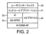
図2は、図1のアーキテクチャーにおいてUE1、2として動作しそして通常のエンドポイント間に同時回路交換及びパケット交換リンクを与えるのに適したターミナルの機能的アーキテクチャーを示す。このアーキテクチャーの上位レベル20は、下位レベル要素とユーザとの間の相互作用を取り扱うユーザインターフェイスである。ユーザインターフェイス20の下には、ターミナルにおいて実行されるアプリケーション21がある。この例では、このアプリケーションは、拡張サービス即ち「リッチコール(rich call)」サービスをサポートできるものである。アプリケーションの下には、パケット交換又は回路交換要求に基づいて、出て行くデータをフォーマットし又は到来するデータを処理する層がある。この例では、パケット交換(PS)層は、上位インターネットプロトコル(IP)層22と、ゲートウェイ汎用パケット無線サービス(G−GPRS)層23とを備えている。回路交換(CS)処理は、CSプロトコル層24により取り扱われる。PS及びCS特有の層は、並列であるのが効果的である。PS及びCS層の下には、3GワイドバンドCDMA(W−CDMA)への無線インターフェイスがある。
FIG. 2 shows a functional architecture of a terminal that operates as
リッチコールサービスを提供するときには、リッチコールアプリケーション(RCA)21は、PS特有の機能22、23及びCS特有の機能24の両方と通信することができる。RCAは、CS及びPS接続の使用を調整し、サービスが利用されるときにユーザインターフェイスを経て一貫したユーザ経験を与える。
When providing a rich call service, a rich call application (RCA) 21 can communicate with both PS-
図2に示す形式の1つのターミナルが、リッチコールサービスにより別のこのようなターミナルと通信すべきときには、各ターミナルのユーザが各ターミナルのアプリケーション21をアクチベートして、サービスをサポートする。アプリケーションは、ネットワーク3を経て互いにネゴシエーションし、サービスをいかに提供すべきか決定する。1つの考えられる構成は、音声データのような遅延に厳格なデータがターミナル間で回路交換接続を経て送信され、そして関連視覚データ又は記述データのようなあまり遅延に厳格でないデータが同じターミナル間でパケット交換接続を経て送信されることにターミナルが合意することである。ターミナルが、このような構成を両方ともサポートしそしてそのやり方に合意することが確立されると、ターミナルは、ネットワークを経て同時回路交換及びパケット交換接続を確立し、次いで、サービスを提供するための通信を続ける。 When one terminal of the type shown in FIG. 2 is to communicate with another such terminal via a rich call service, the user at each terminal activates the application 21 at each terminal to support the service. Applications negotiate with each other over the network 3 to determine how to provide the service. One possible configuration is that delay-sensitive data such as audio data is transmitted between terminals via circuit-switched connections, and less delay-sensitive data such as associated visual data or description data is transmitted between the same terminals. The terminal agrees to be transmitted over the packet switched connection. Once it is established that the terminal supports both such configurations and agrees on how to do so, the terminal establishes simultaneous circuit switched and packet switched connections over the network and then provides services Continue communication.
PS接続を与える1つの好ましい手段は、インターネットプロトコル(IP)である。この場合に、ターミナルは、互いのIPアドレス及びポート番号を知らねばならず、これらは、複合CS及びPS接続を設定するために使用される。この情報は、例えば、ユーザ対ユーザシグナリング(UUS)を使用してターミナル間で通信することができる。1つの特定の解決策は、RFC−2327で定義されたセッション記述プロトコル(SDP)を使用することである。 One preferred means for providing a PS connection is the Internet Protocol (IP). In this case, the terminals must know each other's IP address and port number, which are used to set up a composite CS and PS connection. This information can be communicated between terminals using, for example, user-to-user signaling (UUS). One particular solution is to use the Session Description Protocol (SDP) defined in RFC-2327.
ターミナルのIPアドレス等の情報は、例えば、ユーザが従来のコール中に拡張サービスをアクチベートすると判断した場合には、コール設定プロセス中又はその後のコール中に送信することができる。通常の状況では、前者の解決策が好ましい。
図3を参照して、設定手順の操作の一例を説明する。図3の例は、アン(A)及びボブ(B)と称するユーザ間のホワイトボードセッションの設定を示す。図3は、Aのターミナル30及びBのターミナル31を示す。各ターミナルは、リッチコールアプリケーション32、33と、PS通信を取り扱うためのIPスタック34、35と、CS通信を取り扱うためのCSプロトコル処理構成体36、37とを備えている。ターミナルは、ネットワークの移動交換センター38を経てCS通信に対して接続される。簡単化のために、ネットワークのPSユニットは図示されていない。
Information such as the IP address of the terminal can be transmitted during the call setup process or during subsequent calls if, for example, the user decides to activate the extended service during a conventional call. In normal circumstances, the former solution is preferred.
An example of the operation of the setting procedure will be described with reference to FIG. The example of FIG. 3 shows a whiteboard session setting between users named Ann (A) and Bob (B). FIG. 3 shows A terminal 30 and
この例では、両ターミナルが、最初に、アクティブなPDPコンテクストを、指定のIPアドレスと共に有すると仮定する。他の点では、更に別の設定を行う前にこれを構成することができる。
図3に示すプロセスでは、アンのターミナルがアイコンを表示し、アンはそれをクリックして(40において)、コールを開始する。RCA32は、要求を解釈し、そしてCS接続によりコールの要求を満足するのが好ましいと決定する。従って、ターミナル30及びターミナル31は、ステップ41から50に示す通常のやり方で通信して、ターミナル間にCSコールを確立すると共に、CSベアラチャンネルを使用してスピーチのための経路をオープンする。
In this example, assume that both terminals initially have an active PDP context with a specified IP address. In other respects, this can be configured before making further settings.
In the process shown in FIG. 3, Anne's terminal displays an icon that Anne clicks (at 40) to initiate a call. The RCA 32 interprets the request and determines that it is preferable to satisfy the call request via the CS connection. Accordingly, terminal 30 and terminal 31 communicate in the normal manner shown in
ターミナルは、コール設定中にUUSを経てSDP情報を互いに適当に交換する。
ボブは、ホワイトボードセッションをオープンすることを判断する(51において)。RCA33は、音声及びホワイトボードデータの要求を満足するために並列なCS及びPS接続を使用するのが好ましいと決定する。従って、アプリケーション33は、ホワイトボードセッションを開始することをIPスタック35に通知する(52において)。ターミナル30のIPアドレスが分かっている状態で、ターミナル31は、並列なPSリンクを経てホワイトボードセッションを開始するようインバイトすることをターミナル30に通知する(53において)。IPスタック34は、ホワイトボードセッションが要求されたことをRCA32に通知する(54において)。アンは、ターミナル30のユーザインターフェイスを経て、ホワイトボードセッションを受け入れることを指示する(55において)。RCA32は、要求が受け入れられたことをIPスタックに通知し(56において)、IPスタック34は、200OKメッセージをIPスタック35へ返送し(57において)、これは、ホワイトボードセッションが確立されたことをRCAに指示する(58において)。次いで、ホワイトボードセッションは、59で示すように、パケット交換ベアラチャンネルを使用して続けられる。
Terminals exchange SDP information appropriately with each other via UUS during call setup.
Bob decides to open a whiteboard session (at 51). The
図4に示すように、セッションは、アンがボブとのミーティングを予約するよう要求することにより続けられる。これを行うために、更に別のPS交換を使用して60で一般に示すようにミーティング情報が交換される。この交換は、59で示された形態の進行中の通信セッション/チャンネルを生じない。 As shown in FIG. 4, the session continues by requesting Anne to schedule a meeting with Bob. To do this, meeting information is exchanged as generally indicated at 60 using yet another PS exchange. This exchange does not result in an ongoing communication session / channel of the form indicated at 59.
コールを終了すべきときには、アンは、コールを終了することをRCA32に通知する(61において)。RCAは、進行中のホワイトボードセッションを終了することをIPスタック34に通知する(62において)と共に、CSコールを終了することをCSプロトコル36に通知する(62、63において)。切断メッセージ64、65が通常のやり方で送信される。CSプロトコル37は、終了を開始しなかった当事者のRCA35に、コールを切断すべきであることを通知する(66において)。このRCA35は、ホワイトボードセッションを終了すべきことをIPスタック36に通知し、そしてコールの切断をCSプロトコルに確認する(67及び68において)。確認69、70、71は、次いで、通常のやり方で送信される。CS及びPS接続は、単一の論理通信構成体として取り扱われる。接続のこのリンケージは、ターミナルが、接続の一方が終了された場合にその他方を終了するのが単純であることを意味する。
When the call should be terminated, Ann informs RCA 32 that the call will be terminated (at 61). The RCA notifies the IP stack 34 (at 62) that it will terminate the ongoing whiteboard session and also notifies the CS protocol 36 (at 62, 63) that it will terminate the CS call. Disconnect
エンドユーザアプリケーションは、接続の数及び特性をユーザの観点から透過的に管理し、接続が異なる形式のものであっても、ユーザにとって接続を単純に行いそして終了できるようにする。
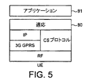
図5及び6は、別の構成を示す。図5及び6の実施形態において、A及びBのターミナルは、適応層80を含む(図5を参照)。この適応層は、CS又はPSコールの確立を、ターミナルで実行されているアプリケーション81にとって透過的であるようにする。適応層は、ターミナルで実行されるべきアプリケーションとは独立してターミナルに設けることができる。適応層は、アプリケーションとCS及びPS通信層との間に位置する。アプリケーションが接続の要求を発生すると、適応層は、その要求を解釈し、それを適宜にCS又はPS層へ通す。
End-user applications transparently manage the number and characteristics of connections from the user's perspective, allowing users to simply make and terminate connections, even if the connections are of different types.
5 and 6 show another configuration. In the embodiment of FIGS. 5 and 6, the A and B terminals include an adaptation layer 80 (see FIG. 5). This adaptation layer makes CS or PS call establishment transparent to the
図6は、図5に示すアーキテクチャーを有するターミナルによりサポートされるオペレーションの一例を示す。図6の例では、2つのターミナル90、91がパケット交換接続により既に通信していると仮定する(92を参照)。ターミナルは、アプリケーション層93、94と、適応層95、96と、IPスタック97、98と、回路交換プロトコルスタック99、100とを有する。ターミナルは、CSコールについてMSC101を経て通信することができる。
FIG. 6 shows an example of operations supported by a terminal having the architecture shown in FIG. In the example of FIG. 6, it is assumed that the two
ユーザAは、ユーザBと音声コールを開始することを判断する。ユーザAは、ユーザAは、自分のターミナルのアプリケーション層93に、音声コールを開始すべきであることを指示する。ターミナルは、PSコールに既に参加しているので、この例では、アプリケーション層が、例えば、SIP(セッション開始プロトコル)フォーマットで、PS接続に適するものとして、相手ターミナルのアドレスに基づいて、要求(例えば、図6に示すようにフォーマットされた)により音声コールを開始すると仮定する。適応層は、PSリンクにわたって音声コールを開始するように試みることができる。しかしながら、この例では、適応層が、CSベアラを使用すべきと判断するものと仮定する。この判断は、ネットワークの能力についての適応ユニットの知識に基づいて行うことができる。図6に示すように、適応層は、IPスタック97を経てBのターミナルへ「SIPインバイト」メッセージを送信する。「インバイト」メッセージは、CSベアラを使用すべきであることを指示するSIPパラメータを含み、AのターミナルのMSISDNを指示する(103を参照)。このMSISDNの知識は、コールの設定要求がBのターミナルに到着するときにBのターミナルがコールを識別できるようにする。
User A determines to initiate a voice call with user B. User A instructs user
Bのターミナルの適応層は、到来する「インバイト」メッセージを検出する。「インバイト」メッセージのフォームは、到来するCSコールの要求を指示するので、ターミナルBのMSISDNを含む200OKメッセージで応答する(104を参照)。ターミナルBのMSISDNの知識は、ターミナルAがそのMSISDNにコールして、差し迫ったCSコールを設定できるようにする。 The adaptation layer of B's terminal detects an incoming “invite” message. The "Invite" message form indicates a request for an incoming CS call, so it responds with a 200 OK message containing the BSIS MSISDN (see 104). Terminal B's knowledge of MSISDN allows terminal A to call that MSISDN and set up an impending CS call.
ターミナルBのMSISDNをもつOKメッセージがターミナルAに到着すると、ターミナルAの適応層95は、そのMSISDNへのコールを確立し始める(105を参照)。受信ターミナルの適応層98は、到来するコールのMSISDNを、ステップ103で受信したものと比較する。それらが一致する場合には、ターミナルBの適応層100に、到来するコールを通知する(106において)。適応層100は、受け入れメッセージ107で応答し、そしてそれに応答して、適応層98は、CSコールを受け入れる(108において)。次いで、CSコールが、同時に、且つ元のIP接続92と同じエンドポイント間に確立される(109において)。
When an OK message with terminal B's MSISDN arrives at terminal A, terminal A's
SIPプロキシー(又はCSCF)が含まれる場合にも、同じ手順を使用することができる。
他の手段を使用して、PS接続を確立してもよい。
2つの従来型のGPRS(汎用パケット無線サービス)ターミナルが回路交換コールに参加する場合には、その各々が他方のE.164番号を知るが、GGSNにより指定される他方のIPアドレスは必ずしも知らない。この場合に、PS接続が既存のCS接続と並列に確立されるべき場合には、ターミナルが他方の各IPアドレスや必要なファイアウオール及び/又はプロキシー横断情報にアクセスするための手段が必要となる。
The same procedure can be used if a SIP proxy (or CSCF) is included.
Other means may be used to establish the PS connection.
When two conventional GPRS (General Packet Radio Service) terminals participate in a circuit switched call, each of them is the other E.P. Know the 164 number, but not necessarily the other IP address specified by the GGSN. In this case, if the PS connection is to be established in parallel with the existing CS connection, a means is required for the terminal to access each other IP address and the necessary firewall and / or proxy traversal information.
この状態では、ボイス・オーバー・IPコールに対して最初に指定されたSIPプロトコル(RFC−2543)を、CSコールの進行中に使用することができる。CSユーザのSIP URLを決定するために、E.164認識からSIP URLへの所定のマッピングがあるのが好ましい。このマッピングは、所定のロジックを使用してもよいし、又はルックアップテーブルとして記憶されてもよい。このようなアドレスマッピングは、ネットワークにおいてSIPプロキシーにより実行することができる(図1の120)。これは、単純なマッピングテーブルを実施してもよいし、又はマッピングを決定するためにサーチされねばならない更に複雑なデータベースを使用してもよい。前者の解決策では、ルックアップテーブルは、例えば、各E.164番号に対応するSIPプロキシーをリストすることができる。
E.165番号 SIPプロキシー オペレータ
+358 40 sip.soneragprs.fi DONERA
+358 41 sipgw.teliagprs.com TELIA
+1 30 mcigprs.com MCI
In this state, the first designated SIP protocol (RFC-2543) for voice over IP calls can be used while the CS call is in progress. In order to determine the SIP URL of the CS user, There is preferably a predetermined mapping from 164 recognition to SIP URL. This mapping may use predetermined logic or may be stored as a lookup table. Such address mapping can be performed by a SIP proxy in the network (120 in FIG. 1). This may implement a simple mapping table or use a more complex database that must be searched to determine the mapping. In the former solution, the lookup table is, for example, each E.D. SIP proxies corresponding to 164 numbers can be listed.
E. 165 number SIP proxy operator
+358 40 sip.soneragprs.fi DONERA
+358 41 sipgw.teliagprs.com TELIA
+1 30 mcigprs.com MCI
後者の解決策では、SIPプロキシーは、DNS SRV記録を使用して本質的にDNS(ドメインネームサービス)問合せサービスを提供する。
CSコール中に、ユーザは、リモート当事者のE.164アドレスを知る。別のターミナルへのPSベアラ接続を開始すべき開始ターミナルのアプリケーションは、E.164アドレスを使用して、SIP INVITE(又はSIP INFO)メッセージを形成しそしてそれをローカルSIPプロキシーへ送信する。行先は、他の当事者のE.164番号(アドレスがユーザ名ではなく電話番号であることを指示するためのタグと共に送信された)であり、そしてそのローカルプロキシーは、そのマッピングテーブル(又はより複雑な機構)を使用して、対応する行先SIPプロキシーを決定する。行先SIPプロキシーの認識は、開始ターミナルへ返送される。開始ターミナルは、INVITE(又はINFO)メッセージを、他のターミナルのE.164認識を指示する行先プロキシーへ送信する。行先プロキシーは、そのE.164認識を使用してターミナルに割り当てられたSIP URLアドレスを決定する。行先プロキシーは、次いで、その要求を上記他のターミナルへそのIPアドレスにより転送することができ、そしてPS接続の設定を通常のように一般的に続けることができる。行先プロキシーは、INVITE(又はINFO)メッセージのペイロードにセッション情報がないことから、メッセージがコール設定を指示しないことを決定できる。
In the latter solution, the SIP proxy essentially provides a DNS (Domain Name Service) query service using DNS SRV records.
During the CS call, the user can connect to the remote party's E.C. Know the 164 address. The application of the initiating terminal that should initiate the PS bearer connection to another terminal is The 164 address is used to form a SIP INVITE (or SIP INFO) message and send it to the local SIP proxy. The destination is the other party's E.D. 164 number (sent with a tag to indicate that the address is a phone number, not a username), and the local proxy responds using its mapping table (or more complex mechanism) The destination SIP proxy to be determined is determined. Recognition of the destination SIP proxy is returned to the initiating terminal. The initiating terminal sends an INVITE (or INFO) message to the E. It transmits to the destination proxy which instruct | indicates 164 recognition. The destination proxy is the E.D. 164 recognition is used to determine the SIP URL address assigned to the terminal. The destination proxy can then forward the request to the other terminal by its IP address and can generally continue setting up the PS connection as usual. The destination proxy can determine that the message does not indicate call setup because there is no session information in the payload of the INVITE (or INFO) message.
例えば、パーズされたペイロード形式又は搬送されるべきデータのサイズに基づいて、適当な勘定手順を適用することができる。例えば、大きな非圧縮の映像ファイルは、小さな圧縮された映像ファイルより転送コストがかかる。又、SIPプロキシーは、日時、ペイロード形式等に基づいて異なるファンクションを適用できる登録サービスも維持することができる。例えば、ユーザは、GIF像を受け取りそして時刻が16:00以降である場合にその映像を指定のe−メールアドレスに転送することを定義できる。 For example, an appropriate accounting procedure can be applied based on the parsed payload format or the size of the data to be carried. For example, a large uncompressed video file costs more to transfer than a small compressed video file. The SIP proxy can also maintain a registration service that can apply different functions based on date and time, payload format, and the like. For example, the user can define to receive a GIF image and forward the video to a designated e-mail address if the time is after 16:00.
或いは又、SIP INVITE又はINFOメッセージ自体を、ユーザデータの転送に使用することもできる。
本発明は、UMTS及びGPRSシステムを参照して説明した。しかしながら、本発明は、これらのシステムに限定されない。
本発明は、ここに暗示的に又は明確に開示した特徴又は特徴の組合せ或いはそれを一般化したものを包含するが、本発明の範囲を何ら限定するものではないことが明らかであろう。以上の説明から、当業者であれば、本発明の範囲内で種々の変更や修正がなされ得ることが明らかであろう。
Alternatively, the SIP INVITE or INFO message itself can be used to transfer user data.
The present invention has been described with reference to UMTS and GPRS systems. However, the present invention is not limited to these systems.
It will be apparent that the invention includes the features or combination of features or generalizations thereof implicitly or explicitly disclosed herein, but does not limit the scope of the invention in any way. From the above description, it will be apparent to those skilled in the art that various changes and modifications can be made within the scope of the present invention.
Claims (72)
前記第1ネットワークアクセスポイントに接続可能な第1端末及び前記第2ネットワークアクセスポイントに接続可能な第2端末であって、各端末が、前記ネットワークを介して単一の論理通信構成体として他方の端末とともに第1形式の接続及び第2形式の接続を同時にサポートすることが可能な、第1端末及び第2端末と、
を具備し、
前記第1形式がパケット交換ベアラであって、前記第2形式が回路交換ベアラであり、又は、前記第1形式が回路交換ベアラであって、前記第2形式がパケット交換ベアラであり、
前記第1形式の接続は、各端末の前記第1のベアラ形式のアドレスを用いた前記第1端末と前記第2端末との間における通信の開始のときに確立され、前記第2の形式の接続は、この後、新たな形式のデータであってその伝送が前記第2形式の接続によりさらに良好にサポートされるものである新たな形式のデータが前記通信に導入される場合に、前記第1端末と前記第2端末との間に確立され、
各端末が、他方の端末の前記第2形式のアドレスを用いて前記第2形式の接続を確立するように構成され、各端末の前記第1形式のアドレスが該端末の前記第2形式のアドレスと異なる、
ことを特徴とする通信システム。The first has a network access point and a second network access point, a network capable of transporting data in between the first network access point by the first bearer and the second bearer second network access point ,
A second terminal connectable to said first first terminal connectable to a network access point and the second network access point, each terminal, the other as a single logical communication structure via the network capable of simultaneously supporting a connection of the connection and the second type of the first type with the terminal, the first terminal及 beauty second terminal,
Comprising
The first type is a packet switched bearer and the second type is a circuit switched bearer, or the first type is a circuit switched bearer and the second type is a packet switched bearer;
The first type connection is established at the start of communication between the first terminal and the second terminal using the first bearer type address of each terminal, and the second type connection A connection is then made when the new type of data is introduced into the communication, which is a new type of data whose transmission is better supported by the connection of the second type. Established between one terminal and the second terminal;
Each terminal is configured to establish the second type connection using the second type address of the other terminal, and the first type address of each terminal is the second type address of the terminal Different from the
A communication system characterized by the above .
回路交換接続を確立する段階と、各端末が該回路交換接続により該端末のパケット交換アドレスを他方の端末に送信する段階と、により、パケット交換接続及び回路交換接続を同時に確立するための動作を実行するように構成される、請求項1に記載の通信システム。 The first terminal and the second terminal are
And establishing a circuit-switched connection, the steps of each terminal transmits to the other terminal of the packet switching address of the terminal by the circuit switched connection, by the operation for establishing a packet switched connection and circuit switched connection simultaneously Ru is configured to perform, the communication system according to claim 1.
回路交換接続を確立する段階と、各端末が前記ネットワークのプロキシサーバと通信して該プロキシサーバから他方の端末のパケット交換アドレスを取得する段階と、によりパケット交換接続及び回路交換接続を同時に確立するための動作を実行するように構成される、請求項1に記載の通信システム。 The first terminal and the second terminal are
Establishing a packet-switched connection and a circuit-switched connection simultaneously by establishing a circuit-switched connection and each terminal communicating with the proxy server of the network to obtain the packet-switched address of the other terminal from the proxy server Ru is configured to perform an operation for the communication system according to claim 1.
前記プロキシサーバが、そのアドレスに応答して、前記他方の端末のパケット交換アドレスを与えるように構成される、請求項4に記載の通信システム。Each terminal is configured to provide the network address of the terminal of the other hand to each proxy server,
The proxy server, in response to the address, the Ru is configured to provide other side of the packet switching address of the terminal, the communication system according to claim 4.
前記第1端末が前記第1ネットワークアクセスポイントに接続する段階と、
前記第2端末が前記第2ネットワークアクセスポイントに接続する段階と、
前記第1端末及び前記第2端末の各々が、他方の端末とともに前記ネットワークを介して単一の論理通信構成体としてパケット交換接続及び回路交換接続を同時にサポートする段階と、を含み、
一方の形式の接続が、各端末の前記第1形式のアドレスを用いた前記第1端末と前記第2端末との間における通信の開始のときに確立され、
他方の形式の接続が、この後、新たな形式のデータであってその伝送が前記他方の形式の接続によりさらに良好にサポートされる新たな形式のデータが前記通信に導入される場合に、前記第1端末と前記第2端末との間に確立され、
各端末が、他方の端末の前記第2形式のアドレスを用いて前記第2形式の接続を確立するように構成され、
前記第1形式がパケット交換ベアラであって、前記第2形式が回路交換ベアラであり、又は、前記第1形式が回路交換ベアラであって、前記第2形式がパケット交換ベアラであり、
各端末の前記第1形式のアドレスが該端末の前記第2形式のアドレスと異なる、
ことを特徴とする方法。The first has a network access point and a second network access point, a network capable of transporting data between said second network access point and the first network access point by the packet switched bearer and a circuit-switched bearer A method of communicating between a first terminal and a second terminal by a communication system comprising :
The method comprising the first terminal is connected to the first network access point,
The method comprising the second terminal is connected to the second network access point,
Wherein each of said first terminal and said second terminal, the steps of simultaneously supporting a packet-switched connection and circuit switched connection as a single logical communication structure through both the network and the other side of the terminal, and
One type of connection is established at the start of communication between the first terminal and the second terminal using the first type address of each terminal,
If the other type of connection is then introduced into the communication, a new type of data that is a new type of data and whose transmission is better supported by the other type of connection, the communication Established between the first terminal and the second terminal;
Each terminal is configured to establish a second type connection using the second type address of the other terminal;
The first type is a packet switched bearer and the second type is a circuit switched bearer, or the first type is a circuit switched bearer and the second type is a packet switched bearer;
The address of the first format of each terminal is different from the address of the second format of the terminal;
A method characterized by that .
該端末は、The terminal
前記他方の端末(2)の前記第1形式のアドレスを用いた該他方の端末(2)との通信の開始のときに前記第1形式の接続を確立し、この後、新たな形式のデータであってその伝送が前記第2形式の接続によりさらに良好にサポートされる新たな形式のデータが前記通信に導入される場合に、前記他方の端末(2)とともに前記第2形式の接続を確立するように構成され、Establishing a connection in the first format at the start of communication with the other terminal (2) using the address in the first format of the other terminal (2), after which a new format of data A connection of the second type is established with the other terminal (2) when a new type of data whose transmission is better supported by the connection of the second type is introduced into the communication Configured to
この場合、前記第1形式の接続がパケット交換接続であって、前記第2形式の接続が回路交換接続であり、又は、前記第1形式の接続が回路交換接続であって、前記第2形式の接続がパケット交換接続であり、In this case, the first type of connection is a packet switched connection and the second type of connection is a circuit switched connection, or the first type of connection is a circuit switched connection and the second type of connection. Is a packet-switched connection,
さらに、前記端末は、前記他方の端末(2)の前記第2形式のアドレスを用いて前記第2形式の接続を確立するように構成され、Further, the terminal is configured to establish the second type connection using the second type address of the other terminal (2),
前記他方の端末(2)の前記第1形式のアドレスが該他方の端末(2)の前記第2形式のアドレスと異なる、The address of the first format of the other terminal (2) is different from the address of the second format of the other terminal (2);
ことを特徴とする端末。A terminal characterized by that.
回路交換接続を確立する段階と、該端末のパケット交換アドレスを該回路交換接続により前記他方の端末に対して送信する段階と、により、パケット交換接続及び回路交換接続を同時に確立するための動作を実行するように構成される、請求項29に記載の端末。An operation for simultaneously establishing a packet switched connection and a circuit switched connection by establishing a circuit switched connection and transmitting the packet switched address of the terminal to the other terminal by the circuit switched connection; 30. The terminal of claim 29, configured to execute.
前記プロキシサーバが、そのアドレスに応答して前記他方の端末のパケット交換アドレスを与えるように構成される、請求項32に記載の端末。The terminal of claim 32, wherein the proxy server is configured to provide a packet switched address of the other terminal in response to the address.
該装置が、前記他方の端末(2)の前記第1形式のアドレスを用いた該他方の端末(2)との通信の開始のときに前記第1形式の接続を確立し、この後、新たな形式のデータであってその伝送が前記第2形式の接続によりさらに良好にサポートされる新たなデータが、前記通信に導入される場合に、前記他方の端末(2)とともに前記第2形式の接続を確立すること、を実行するように構成されており、The apparatus establishes a connection of the first type at the start of communication with the other terminal (2) using the address of the first type of the other terminal (2). New data that is better supported by the second type of connection and is introduced into the communication, the second type of data together with the other terminal (2) To establish a connection, and
前記第1形式がパケット交換であって、前記第2形式が回路交換であり、又は、前記第1形式が回路交換であって、前記第2形式がパケット交換であり、The first format is packet switching and the second format is circuit switching; or the first format is circuit switching and the second format is packet switching;
前記装置が、前記他方の端末(2)の前記第2形式のアドレスを用いて該第2形式の接続を確立するように構成されており、The device is configured to establish a second type connection using the second type address of the other terminal (2);
前記他方の端末(2)の前記第1形式のアドレスが該他方の端末(2)の前記第2形式のアドレスと異なる、The address of the first format of the other terminal (2) is different from the address of the second format of the other terminal (2);
ことを特徴とする装置。A device characterized by that.
前記第1端末(1)が、前記ネットワークのアクセスポイントに接続し、該ネットワークを介して単一の論理通信構成体として他方の端末(2)とともに第1形式の接続及び第2形式の接続を同時にサポートし、The first terminal (1) is connected to the access point of the network, and the first type of connection and the second type of connection are made with the other terminal (2) as a single logical communication construct via the network. Support at the same time,
前記第1端末(1)が、前記他方の端末の前記第1形式のアドレスを用いた該他方の端末との通信の開始のときに、前記第1形式の通信を確立し、この後、新たな形式のデータであってその伝送が前記第2形式の接続によりさらに良好にサポートされる新たなデータが前記通信に導入される場合に、前記他方の端末とともに前記第2形式の接続を確立し、The first terminal (1) establishes communication in the first format at the start of communication with the other terminal using the address in the first format of the other terminal. When new data is introduced into the communication that is better supported by the second type connection, the second type connection is established with the other terminal. ,
前記第1形式がパケット交換であって、前記第2形式が回路交換であり、又は、前記第1形式が回路交換であって、前記第2形式がパケット交換であり、The first format is packet switching and the second format is circuit switching; or the first format is circuit switching and the second format is packet switching;
前記第1端末(1)が前記他方の端末の前記第2形式のアドレスを用いて該第2形式の接続を確立し、The first terminal (1) establishes a second type connection using the second type address of the other terminal;
前記他方の端末の前記第1形式のアドレスが前記他方の端末の前記第2形式のアドレスと異なる、The address of the first format of the other terminal is different from the address of the second format of the other terminal;
ことを特徴とする方法。A method characterized by that.
前記装置が、前記第2端末の第1形式のアドレスを用いた該第2端末との通信の開始のときに、前記第1形式の接続を確立し、この後、新たなデータであってその伝送が前記第2形式の接続によりさらに良好にサポートされる新たなデータが、前記通信に導入される場合に、前記第2端末とともに前記第2形式の接続を確立し、The device establishes a connection in the first format at the start of communication with the second terminal using the first format address of the second terminal, after which new data Establishing new type of connection with the second terminal when new data is introduced into the communication, the transmission of which is better supported by the second type of connection;
前記第1形式がパケット交換型であって、前記第2形式が回路交換型であり、又は、前記第1形式が回路交換型であって、前記第2形式がパケット交換型であり、The first format is a packet switched type, the second format is a circuit switched type, or the first format is a circuit switched type, and the second format is a packet switched type,
前記装置が、前記第2端末の前記第2形式のアドレスを用いて前記第2形式の接続を確立するように構成され、The apparatus is configured to establish the second type connection using the second type address of the second terminal;
前記第2端末の前記第1形式のアドレスが該第2端末の前記第2形式のアドレスと異なる、The first terminal address of the second terminal is different from the second terminal address of the second terminal;
ことを特徴とする方法。A method characterized by that.
Applications Claiming Priority (2)
| Application Number | Priority Date | Filing Date | Title |
|---|---|---|---|
| GBGB0115996.1A GB0115996D0 (en) | 2001-06-29 | 2001-06-29 | Circuit-switched and packet-switched communications |
| PCT/IB2002/003164 WO2003003767A1 (en) | 2001-06-29 | 2002-06-28 | Circuit-switched and packet-switched communications |
Publications (3)
| Publication Number | Publication Date |
|---|---|
| JP2005507578A JP2005507578A (en) | 2005-03-17 |
| JP2005507578A5 JP2005507578A5 (en) | 2005-12-22 |
| JP4217606B2 true JP4217606B2 (en) | 2009-02-04 |
Family
ID=9917661
Family Applications (1)
| Application Number | Title | Priority Date | Filing Date |
|---|---|---|---|
| JP2003509802A Expired - Lifetime JP4217606B2 (en) | 2001-06-29 | 2002-06-28 | Circuit switched and packet switched communications |
Country Status (18)
| Country | Link |
|---|---|
| US (1) | US7600009B2 (en) |
| EP (2) | EP1400137B1 (en) |
| JP (1) | JP4217606B2 (en) |
| KR (1) | KR100701637B1 (en) |
| CN (2) | CN1611084B (en) |
| AT (1) | ATE493009T1 (en) |
| BR (2) | BR0210757A (en) |
| CA (1) | CA2451988C (en) |
| DE (1) | DE60238678D1 (en) |
| DK (1) | DK2265080T3 (en) |
| ES (2) | ES2354967T3 (en) |
| GB (1) | GB0115996D0 (en) |
| MX (1) | MXPA04000067A (en) |
| PT (1) | PT2265080E (en) |
| RU (2) | RU2334372C2 (en) |
| UA (1) | UA86919C2 (en) |
| WO (1) | WO2003003767A1 (en) |
| ZA (1) | ZA200400010B (en) |
Cited By (1)
| Publication number | Priority date | Publication date | Assignee | Title |
|---|---|---|---|---|
| US9532978B2 (en) | 2010-12-27 | 2017-01-03 | Intervet Inc. | Topical localized isoxazoline formulation |
Families Citing this family (74)
| Publication number | Priority date | Publication date | Assignee | Title |
|---|---|---|---|---|
| US7333505B2 (en) * | 2000-12-18 | 2008-02-19 | Nortel Networks Limited | Transaction management for interworking between disparate networks |
| EP1495583A1 (en) * | 2002-04-16 | 2005-01-12 | Nokia Corporation | Handling a request to establish a packet switched session |
| US7639601B2 (en) * | 2002-07-05 | 2009-12-29 | Nortel Networks Limited | Methods and apparatus for data communication |
| US6879828B2 (en) | 2002-09-09 | 2005-04-12 | Nokia Corporation | Unbroken primary connection switching between communications services |
| FR2850518B1 (en) * | 2003-01-29 | 2005-05-20 | Evolium Sas | METHOD FOR SIMULTANEOUSLY ACCESSING CIRCUIT SERVICES AND PACKET SERVICES IN A CELLULAR MOBILE RADIOCOMMUNICATIONS SYSTEM |
| GB2398458B (en) * | 2003-02-15 | 2005-05-25 | Ericsson Telefon Ab L M | Conversational bearer negotiation |
| TW200509628A (en) | 2003-04-15 | 2005-03-01 | Ericsson Telefon Ab L M | Bandwidth on demand for media services at stationary equipment unit |
| US7646710B2 (en) | 2003-07-28 | 2010-01-12 | Nortel Networks Limited | Mobility in a multi-access communication network |
| GB0321424D0 (en) * | 2003-09-12 | 2003-10-15 | Ericsson Telefon Ab L M | Bearer setup in a multimedia service |
| US6994245B2 (en) | 2003-10-17 | 2006-02-07 | James M. Pinchot | Micro-reactor fabrication |
| US7359373B2 (en) * | 2003-10-17 | 2008-04-15 | Nokia Corporation | System, apparatus, and method for establishing circuit-switched communications via packet-switched network signaling |
| GB2408654B (en) * | 2003-11-26 | 2006-01-11 | Motorola Inc | A cellular communication system and a method of operation therefor |
| DE102004007216A1 (en) * | 2004-02-13 | 2005-09-01 | Siemens Ag | A method for switching between a packet-oriented PTT session and a circuit-oriented telephone connection between at least two radio communication devices, associated radio communication device, network component and radio communication system |
| US7624188B2 (en) * | 2004-05-03 | 2009-11-24 | Nokia Corporation | Apparatus and method to provide conference data sharing between user agent conference participants |
| SE0401671D0 (en) * | 2004-06-29 | 2004-06-29 | Ericsson Telefon Ab L M | Network control of a combined circuit switched and packet switched session |
| MY145725A (en) * | 2004-07-30 | 2012-03-30 | Ericsson Telefon Ab L M | Method and system for retrieving network addresses in hybrid telecommunication networks |
| KR101149968B1 (en) | 2004-07-30 | 2012-06-04 | 텔레폰악티에볼라겟엘엠에릭슨(펍) | A method and device for providing correlation means in hybrid telecommunication networks |
| US8036244B2 (en) * | 2004-08-06 | 2011-10-11 | Sharp Kabushiki Kaisha | Transmitter, receiver, communication system, communication method, non-transitory computer readable medium |
| DE602005012817D1 (en) | 2004-09-30 | 2009-04-02 | Huawei Tech Co Ltd | PROCESS SYSTEM FOR REALIZING COMMUNICATION |
| CN100352295C (en) * | 2005-01-24 | 2007-11-28 | 华为技术有限公司 | Method for realizing IP multi media sub-system conversation falling to circuit switching call |
| CN101061729B (en) * | 2004-10-06 | 2011-11-02 | 意大利电信股份公司 | Method and related mobile communication system for providing combinational network services |
| GB2419258B (en) * | 2004-10-13 | 2007-04-18 | Siemens Ag | User preference for packet switched or circuit switched call in dual transfer mode |
| WO2006046577A1 (en) * | 2004-10-29 | 2006-05-04 | Nippon Telegraph And Telephone Corporation | Packet communication network and packet communication method |
| BRPI0419224B8 (en) * | 2004-11-15 | 2018-06-05 | Ericsson Telefon Ab L M | method for simultaneously enabling multimedia packet-switched communication during a switched circuit call, and mobile terminal |
| MX2007005842A (en) * | 2004-11-30 | 2007-07-04 | Ericsson Telefon Ab L M | Method for smm capability distribution. |
| ES2529680T3 (en) | 2004-12-03 | 2015-02-24 | Telecom Italia S.P.A. | Activation of combinational services in a communications network |
| EP1820306B1 (en) * | 2004-12-08 | 2013-08-28 | Telefonaktiebolaget L M Ericsson (publ) | Method and node of controlling the allocation of transmission resources to wireless terminals within a radio access network |
| EP1672866A1 (en) * | 2004-12-15 | 2006-06-21 | Siemens S.p.A. | Method and system to the instant transfer of multimedia files between mobile radio users within the scope of combinational services |
| EP1672867A1 (en) * | 2004-12-15 | 2006-06-21 | Siemens S.p.A. | Method to the fast and reliable transfer of large amount of data between mobile radio users involved in a SIP session |
| CN100407861C (en) * | 2004-12-21 | 2008-07-30 | 华为技术有限公司 | Method for implementing multimedia service calling in circuit domain |
| JP4523650B2 (en) * | 2004-12-21 | 2010-08-11 | テレフオンアクチーボラゲット エル エム エリクソン(パブル) | Method and apparatus for providing information on multimedia options |
| KR100902341B1 (en) | 2005-01-28 | 2009-06-12 | 샤프 가부시키가이샤 | Communication device, communication system, communication method, computer-readable recording media having communication program recorded therein, and communication circuit |
| GB0501829D0 (en) * | 2005-01-28 | 2005-03-09 | Nokia Corp | Providing services in a communication system |
| JP4198741B2 (en) | 2005-01-28 | 2008-12-17 | シャープ株式会社 | Communication device, communication system, communication method, communication program, communication circuit |
| KR101029814B1 (en) * | 2005-02-04 | 2011-04-20 | 엘지전자 주식회사 | Method for Transmitting and Receiving Data Using PS and CS |
| US7826408B1 (en) | 2005-03-14 | 2010-11-02 | Ozmo, Inc. | Apparatus and method for integrating short-range wireless personal area networks for a wireless local area network infrastructure |
| PL1867184T3 (en) | 2005-04-06 | 2011-07-29 | Ericsson Telefon Ab L M | A method, an apparatus and a system for uplink establishment in a wireless cellular communication having a delay dependent on connection type |
| CN100466639C (en) * | 2005-06-18 | 2009-03-04 | 华为技术有限公司 | Method for realizing two-directional interacting of circuit zone and grouping zone, and system therefor |
| US8401004B2 (en) | 2005-06-21 | 2013-03-19 | Lg Electronics Inc. | Terminal, method and system for performing combination service using terminal capability version |
| EP1900118B1 (en) * | 2005-06-21 | 2014-04-09 | LG Electronics Inc. | Terminal, method and system for performing combination service using terminal capability version |
| EP1969825B1 (en) * | 2005-12-07 | 2011-03-30 | Telefonaktiebolaget LM Ericsson (publ) | Method and network unit for setting up a connection in a second network |
| EP1958467B1 (en) * | 2005-12-09 | 2012-02-08 | Telecom Italia S.p.A. | Method of enabling a combinational service and communication network implementing the service |
| EP1799005B1 (en) * | 2005-12-15 | 2013-03-06 | Alcatel Lucent | A method to access subscription data stored in a database entity in a mobile communication network |
| US9723520B1 (en) | 2005-12-20 | 2017-08-01 | Microsoft Technology Licensing, Llc | Location based mode switching for dual mode mobile terminals |
| US7710950B2 (en) * | 2006-02-06 | 2010-05-04 | Research In Motion Limited | System and methods for originating a SIP call via a circuit-switched network from a user equipment device |
| TWI419517B (en) * | 2006-01-31 | 2013-12-11 | Interdigital Tech Corp | Method for supporting circuit switched interworking |
| US8432899B2 (en) | 2007-02-22 | 2013-04-30 | Aylus Networks, Inc. | Systems and methods for enabling IP signaling in wireless networks |
| US9026117B2 (en) | 2006-05-16 | 2015-05-05 | Aylus Networks, Inc. | Systems and methods for real-time cellular-to-internet video transfer |
| US20070286370A1 (en) * | 2006-05-24 | 2007-12-13 | Kauppinen Risto A | Apparatuses and methods for presenting caller identities for communications originating and terminating in different communication domains |
| FI118711B (en) * | 2006-05-29 | 2008-02-15 | Teliasonera Ab | Improved use of parallel media flows |
| FI119349B (en) * | 2006-06-22 | 2008-10-15 | Teliasonera Ab | Establishing a peer-to-peer packet-switched connection |
| ES2451499T3 (en) * | 2006-10-16 | 2014-03-27 | Motorola Mobility Llc | System and procedure to provide combined services to anonymous parties who call |
| US7983240B2 (en) | 2006-10-16 | 2011-07-19 | Telefonaktiebolaget Lm Ericsson (Publ) | System and method for communication session correlation |
| CN101595714B (en) * | 2007-01-15 | 2013-06-12 | Lm爱立信电话有限公司 | Method and arrangements for circuit switched services in communication networks |
| US20080317010A1 (en) * | 2007-06-22 | 2008-12-25 | Aylus Networks, Inc. | System and method for signaling optimization in ims services by using a service delivery platform |
| US8873521B2 (en) * | 2007-07-06 | 2014-10-28 | Sony Corporation | Methods of determining information regarding remote user terminals and related systems and computer program products |
| US8539098B2 (en) | 2007-10-17 | 2013-09-17 | Dispersive Networks, Inc. | Multiplexed client server (MCS) communications and systems |
| US8560634B2 (en) * | 2007-10-17 | 2013-10-15 | Dispersive Networks, Inc. | Apparatus, systems and methods utilizing dispersive networking |
| CN101453718B (en) * | 2007-11-30 | 2011-08-03 | 中国移动通信集团公司 | Method, device and system for triggering packet domain connection during circuit domain call |
| US9083793B2 (en) * | 2008-11-21 | 2015-07-14 | At&T Intellectual Property I, L.P. | Method and apparatus for providing network based services to private branch exchange endpoints |
| US20100150144A1 (en) * | 2008-12-12 | 2010-06-17 | Bernard Ku | Method and apparatus for completing a circuit switched service call in an internet protocol network |
| US9319942B2 (en) * | 2009-05-18 | 2016-04-19 | Nokia Technologies Oy | Systems, methods, and apparatuses for facilitating a circuit switched connection |
| JP4608005B1 (en) * | 2009-07-03 | 2011-01-05 | 株式会社エヌ・ティ・ティ・ドコモ | Mobile communication method, mobile communication system, subscriber management server device and switching center |
| US8948108B2 (en) * | 2009-10-21 | 2015-02-03 | Telefonaktiebolaget L M Ericsson (Publ) | Resource reservation in multiple accesses |
| WO2011145949A1 (en) * | 2010-05-18 | 2011-11-24 | Sibcom As | Method, system and devices for the establishment of a secure communication session |
| EP2418815B1 (en) * | 2010-08-12 | 2019-01-02 | Deutsche Telekom AG | Managing Session Initiation Protocol communications towards a user entity in a communication network |
| US8955110B1 (en) | 2011-01-14 | 2015-02-10 | Robert W. Twitchell, Jr. | IP jamming systems utilizing virtual dispersive networking |
| US8941659B1 (en) | 2011-01-28 | 2015-01-27 | Rescon Ltd | Medical symptoms tracking apparatus, methods and systems |
| US20120327790A1 (en) * | 2011-06-24 | 2012-12-27 | Mediatek Inc. | Apparatuses and methods for coordinating circuit switched (cs) services in packet transfer mode (ptm) |
| ES2404954B1 (en) * | 2011-07-06 | 2014-05-14 | Telefónica, S.A. | METHOD AND SYSTEM TO DISCOVER AND ESTABLISH A COMMUNICATION CHANNEL ENRICHED IN A VOICE CALL |
| US9462628B2 (en) | 2011-07-11 | 2016-10-04 | Qualcomm Incorporated | Apparatus and method for maintaining a circuit-switched voice call in a multi-RAB wireless communication system in an area of weak coverage |
| GB201211580D0 (en) | 2012-06-29 | 2012-08-15 | Microsoft Corp | Determining suitablity of an access network |
| GB201211565D0 (en) | 2012-06-29 | 2012-08-15 | Microsoft Corp | Determining availability of an acess network |
| GB201211568D0 (en) | 2012-06-29 | 2012-08-15 | Microsoft Corp | Determining network availability based on geographical location |
Family Cites Families (18)
| Publication number | Priority date | Publication date | Assignee | Title |
|---|---|---|---|---|
| US6185619B1 (en) * | 1996-12-09 | 2001-02-06 | Genuity Inc. | Method and apparatus for balancing the process load on network servers according to network and serve based policies |
| FI114178B (en) * | 1995-01-09 | 2004-08-31 | Nokia Corp | Dynamic allocation of radio capacity in a TDMA system |
| US6345145B1 (en) * | 1995-08-25 | 2002-02-05 | Sony Corporation | Signal recording/reproducing method and apparatus, signal record medium and signal transmission/reception method and apparatus |
| US5781547A (en) * | 1996-02-29 | 1998-07-14 | Motorola, Inc. | Router and method for use in a communication system |
| US6122263A (en) * | 1997-06-10 | 2000-09-19 | Telefonaktiebolaget Lm Ericsson | Internet access for cellular networks |
| US6608832B2 (en) * | 1997-09-25 | 2003-08-19 | Telefonaktiebolaget Lm Ericsson | Common access between a mobile communications network and an external network with selectable packet-switched and circuit-switched and circuit-switched services |
| GB2335825B (en) * | 1998-03-27 | 2001-07-18 | 3Com Technologies Ltd | Dual-circuit telephony |
| US6343318B1 (en) * | 1998-05-29 | 2002-01-29 | Palm, Inc. | Method and apparatus for communicating information over low bandwidth communications networks |
| JP4307728B2 (en) * | 1998-06-19 | 2009-08-05 | テレフオンアクチーボラゲット エル エム エリクソン(パブル) | Method and apparatus for dynamically adapting communication state of mobile communication system |
| US6862622B2 (en) * | 1998-07-10 | 2005-03-01 | Van Drebbel Mariner Llc | Transmission control protocol/internet protocol (TCP/IP) packet-centric wireless point to multi-point (PTMP) transmission system architecture |
| US6452915B1 (en) * | 1998-07-10 | 2002-09-17 | Malibu Networks, Inc. | IP-flow classification in a wireless point to multi-point (PTMP) transmission system |
| JP3239859B2 (en) * | 1998-09-24 | 2001-12-17 | 日本電気株式会社 | Mobile communication system and communication method thereof |
| FI109444B (en) * | 1999-01-11 | 2002-07-31 | Nokia Corp | Method and system for parallel use of data transmission channels |
| US6760775B1 (en) * | 1999-03-05 | 2004-07-06 | At&T Corp. | System, method and apparatus for network service load and reliability management |
| FI991092A (en) | 1999-05-12 | 2000-11-13 | Nokia Networks Oy | A method for improving the quality of a communication connection and a network element |
| US6992994B2 (en) * | 2000-04-17 | 2006-01-31 | Telcordia Technologies, Inc. | Methods and systems for a generalized mobility solution using a dynamic tunneling agent |
| US6721565B1 (en) * | 2000-08-07 | 2004-04-13 | Lucent Technologies Inc. | Handover of wireless calls between systems supporting circuit and packet call models |
| US20020062379A1 (en) * | 2000-11-06 | 2002-05-23 | Widegren Ina B. | Method and apparatus for coordinating quality of service requirements for media flows in a multimedia session with IP bearer services |
-
2001
- 2001-06-29 GB GBGB0115996.1A patent/GB0115996D0/en not_active Ceased
-
2002
- 2002-06-28 AT AT02765148T patent/ATE493009T1/en not_active IP Right Cessation
- 2002-06-28 JP JP2003509802A patent/JP4217606B2/en not_active Expired - Lifetime
- 2002-06-28 RU RU2004102514/09A patent/RU2334372C2/en active
- 2002-06-28 CN CN028142217A patent/CN1611084B/en not_active Expired - Lifetime
- 2002-06-28 WO PCT/IB2002/003164 patent/WO2003003767A1/en active Application Filing
- 2002-06-28 UA UA2004010108A patent/UA86919C2/en unknown
- 2002-06-28 EP EP02765148A patent/EP1400137B1/en not_active Expired - Lifetime
- 2002-06-28 ES ES02765148T patent/ES2354967T3/en not_active Expired - Lifetime
- 2002-06-28 CN CN201210246810.6A patent/CN102883462B/en not_active Expired - Lifetime
- 2002-06-28 DK DK10180142.1T patent/DK2265080T3/en active
- 2002-06-28 KR KR1020037017058A patent/KR100701637B1/en active IP Right Grant
- 2002-06-28 ES ES10180142T patent/ES2430392T3/en not_active Expired - Lifetime
- 2002-06-28 DE DE60238678T patent/DE60238678D1/en not_active Expired - Lifetime
- 2002-06-28 PT PT101801421T patent/PT2265080E/en unknown
- 2002-06-28 EP EP10180142.1A patent/EP2265080B1/en not_active Expired - Lifetime
- 2002-06-28 MX MXPA04000067A patent/MXPA04000067A/en active IP Right Grant
- 2002-06-28 BR BR0210757-0A patent/BR0210757A/en active IP Right Grant
- 2002-06-28 BR BRPI0210757-0A patent/BRPI0210757B1/en unknown
- 2002-06-28 CA CA002451988A patent/CA2451988C/en not_active Expired - Lifetime
- 2002-06-28 US US10/482,047 patent/US7600009B2/en not_active Expired - Lifetime
-
2004
- 2004-01-05 ZA ZA200400010A patent/ZA200400010B/en unknown
-
2008
- 2008-05-08 RU RU2008118379/07A patent/RU2463744C2/en active
Cited By (1)
| Publication number | Priority date | Publication date | Assignee | Title |
|---|---|---|---|---|
| US9532978B2 (en) | 2010-12-27 | 2017-01-03 | Intervet Inc. | Topical localized isoxazoline formulation |
Also Published As
| Publication number | Publication date |
|---|---|
| ATE493009T1 (en) | 2011-01-15 |
| ES2354967T3 (en) | 2011-03-21 |
| PT2265080E (en) | 2013-10-16 |
| RU2463744C2 (en) | 2012-10-10 |
| US7600009B2 (en) | 2009-10-06 |
| WO2003003767A1 (en) | 2003-01-09 |
| MXPA04000067A (en) | 2004-05-21 |
| BR0210757A (en) | 2004-07-20 |
| CA2451988C (en) | 2009-10-06 |
| US20040252674A1 (en) | 2004-12-16 |
| ES2430392T3 (en) | 2013-11-20 |
| DK2265080T3 (en) | 2013-10-28 |
| CN1611084A (en) | 2005-04-27 |
| DE60238678D1 (en) | 2011-02-03 |
| CA2451988A1 (en) | 2003-01-09 |
| UA86919C2 (en) | 2009-06-10 |
| BRPI0210757B1 (en) | 2017-06-13 |
| GB0115996D0 (en) | 2001-08-22 |
| CN1611084B (en) | 2012-09-05 |
| KR20040010784A (en) | 2004-01-31 |
| EP2265080A1 (en) | 2010-12-22 |
| RU2004102514A (en) | 2005-06-27 |
| ZA200400010B (en) | 2004-08-17 |
| CN102883462A (en) | 2013-01-16 |
| RU2334372C2 (en) | 2008-09-20 |
| EP1400137A1 (en) | 2004-03-24 |
| CN102883462B (en) | 2017-04-12 |
| EP1400137B1 (en) | 2010-12-22 |
| EP2265080B1 (en) | 2013-08-21 |
| KR100701637B1 (en) | 2007-03-30 |
| JP2005507578A (en) | 2005-03-17 |
| RU2008118379A (en) | 2009-11-20 |
Similar Documents
| Publication | Publication Date | Title |
|---|---|---|
| JP4217606B2 (en) | Circuit switched and packet switched communications | |
| US7058042B2 (en) | One-to-one communication | |
| EP1771983B1 (en) | A method and device for providing correlation means in hybrid telecommunication networks | |
| KR100797168B1 (en) | Setting up communication sessions | |
| US8717876B2 (en) | Providing packet-based multimedia services via a circuit bearer | |
| US7613147B2 (en) | Packet-based conversational service for a multimedia session in a mobile communications system | |
| EP1772003B1 (en) | Method and system for retrieving network addresses in hybrid telecommunication networks | |
| US7870269B2 (en) | Method and system for activating a packet data subscriber context for packet data | |
| US20040109459A1 (en) | Packet filter provisioning to a packet data access node | |
| US9356973B2 (en) | Method for the transmission of signalling data in a network interface unit and in a control unit and corresponding devices | |
| JP4268129B2 (en) | Signaling packet delivery control with specific commands from applications to optimize delivery to wireless networks | |
| JP2008523662A (en) | Image-based push-to-talk user interface image exchange method | |
| EP1380182B1 (en) | One-to-one communication in a system having different control plane and user plane logical entities | |
| US7024197B2 (en) | Wireless mid-call transfers | |
| WO2003107618A1 (en) | Megaco protocol with user termination | |
| JP4078381B2 (en) | Method and apparatus for push-to-talk | |
| AU2002329518B2 (en) | Circuit-switched and packet-switched communications | |
| AU2002329518A1 (en) | Circuit-switched and packet-switched communications |
Legal Events
| Date | Code | Title | Description |
|---|---|---|---|
| A521 | Request for written amendment filed |
Free format text: JAPANESE INTERMEDIATE CODE: A523 Effective date: 20050221 |
|
| A621 | Written request for application examination |
Free format text: JAPANESE INTERMEDIATE CODE: A621 Effective date: 20050221 |
|
| A977 | Report on retrieval |
Free format text: JAPANESE INTERMEDIATE CODE: A971007 Effective date: 20070405 |
|
| A131 | Notification of reasons for refusal |
Free format text: JAPANESE INTERMEDIATE CODE: A131 Effective date: 20080107 |
|
| A601 | Written request for extension of time |
Free format text: JAPANESE INTERMEDIATE CODE: A601 Effective date: 20080407 |
|
| A602 | Written permission of extension of time |
Free format text: JAPANESE INTERMEDIATE CODE: A602 Effective date: 20080414 |
|
| A521 | Request for written amendment filed |
Free format text: JAPANESE INTERMEDIATE CODE: A523 Effective date: 20080704 |
|
| TRDD | Decision of grant or rejection written | ||
| A01 | Written decision to grant a patent or to grant a registration (utility model) |
Free format text: JAPANESE INTERMEDIATE CODE: A01 Effective date: 20081020 |
|
| A01 | Written decision to grant a patent or to grant a registration (utility model) |
Free format text: JAPANESE INTERMEDIATE CODE: A01 |
|
| A61 | First payment of annual fees (during grant procedure) |
Free format text: JAPANESE INTERMEDIATE CODE: A61 Effective date: 20081110 |
|
| R150 | Certificate of patent or registration of utility model |
Free format text: JAPANESE INTERMEDIATE CODE: R150 Ref document number: 4217606 Country of ref document: JP Free format text: JAPANESE INTERMEDIATE CODE: R150 |
|
| FPAY | Renewal fee payment (event date is renewal date of database) |
Free format text: PAYMENT UNTIL: 20111114 Year of fee payment: 3 |
|
| FPAY | Renewal fee payment (event date is renewal date of database) |
Free format text: PAYMENT UNTIL: 20111114 Year of fee payment: 3 |
|
| FPAY | Renewal fee payment (event date is renewal date of database) |
Free format text: PAYMENT UNTIL: 20121114 Year of fee payment: 4 |
|
| R250 | Receipt of annual fees |
Free format text: JAPANESE INTERMEDIATE CODE: R250 |
|
| FPAY | Renewal fee payment (event date is renewal date of database) |
Free format text: PAYMENT UNTIL: 20121114 Year of fee payment: 4 |
|
| FPAY | Renewal fee payment (event date is renewal date of database) |
Free format text: PAYMENT UNTIL: 20131114 Year of fee payment: 5 |
|
| R250 | Receipt of annual fees |
Free format text: JAPANESE INTERMEDIATE CODE: R250 |
|
| R250 | Receipt of annual fees |
Free format text: JAPANESE INTERMEDIATE CODE: R250 |
|
| R250 | Receipt of annual fees |
Free format text: JAPANESE INTERMEDIATE CODE: R250 |
|
| S531 | Written request for registration of change of domicile |
Free format text: JAPANESE INTERMEDIATE CODE: R313531 |
|
| R350 | Written notification of registration of transfer |
Free format text: JAPANESE INTERMEDIATE CODE: R350 |
|
| S111 | Request for change of ownership or part of ownership |
Free format text: JAPANESE INTERMEDIATE CODE: R313113 |
|
| R250 | Receipt of annual fees |
Free format text: JAPANESE INTERMEDIATE CODE: R250 |
|
| R360 | Written notification for declining of transfer of rights |
Free format text: JAPANESE INTERMEDIATE CODE: R360 |
|
| R360 | Written notification for declining of transfer of rights |
Free format text: JAPANESE INTERMEDIATE CODE: R360 |
|
| R371 | Transfer withdrawn |
Free format text: JAPANESE INTERMEDIATE CODE: R371 |
|
| S111 | Request for change of ownership or part of ownership |
Free format text: JAPANESE INTERMEDIATE CODE: R313113 |
|
| R350 | Written notification of registration of transfer |
Free format text: JAPANESE INTERMEDIATE CODE: R350 |
|
| R250 | Receipt of annual fees |
Free format text: JAPANESE INTERMEDIATE CODE: R250 |
|
| R250 | Receipt of annual fees |
Free format text: JAPANESE INTERMEDIATE CODE: R250 |
|
| R250 | Receipt of annual fees |
Free format text: JAPANESE INTERMEDIATE CODE: R250 |
|
| R250 | Receipt of annual fees |
Free format text: JAPANESE INTERMEDIATE CODE: R250 |
|
| R250 | Receipt of annual fees |
Free format text: JAPANESE INTERMEDIATE CODE: R250 |
|
| R250 | Receipt of annual fees |
Free format text: JAPANESE INTERMEDIATE CODE: R250 |
|
| EXPY | Cancellation because of completion of term |