JP4215577B2 - Plug with extraction jig - Google Patents
Plug with extraction jig Download PDFInfo
- Publication number
- JP4215577B2 JP4215577B2 JP2003181175A JP2003181175A JP4215577B2 JP 4215577 B2 JP4215577 B2 JP 4215577B2 JP 2003181175 A JP2003181175 A JP 2003181175A JP 2003181175 A JP2003181175 A JP 2003181175A JP 4215577 B2 JP4215577 B2 JP 4215577B2
- Authority
- JP
- Japan
- Prior art keywords
- plug
- knob
- extraction
- removal
- adapter
- Prior art date
- Legal status (The legal status is an assumption and is not a legal conclusion. Google has not performed a legal analysis and makes no representation as to the accuracy of the status listed.)
- Expired - Fee Related
Links
Images


Landscapes
- Mechanical Coupling Of Light Guides (AREA)
- Details Of Connecting Devices For Male And Female Coupling (AREA)
Description
【0001】
【発明の属する技術分野】
本発明は、抜き治具付きプラグに係り、詳しくは、主に光ファイバ用のコネクタに嵌合されるプラグを、ワンタッチで抜きやすくし、更に、実装密度を上げた抜き治具付きプラグに関する。
【0002】
【従来の技術】
従来において、光ファイバー用のコネクタで、例えば、SC形光コネクタに嵌合されるケーブル用プラグは、実装密度を上げるために、プラグ抜去用の部品を削除して高さが高くならないようにしている。
【0003】
よって、嵌合させた前記プラグをコネクタから抜去させるには、別体の専用工具が必要であって、使い勝手上で不便であった。そこで、抜き治具付プラグが提案されて知られている(例えば、特許文献1参照。)。
【0004】
【特許文献1】
実用新案登録第2579870号公報(第2−4頁、第1図)
【0005】
【発明が解決しようとする課題】
しかしながら、この場合でも、アダプタからプラグを抜き取るには、▲1▼抜き治具を抜き取り方向とは逆方向に押し込み、アダプタロックを解除する、▲2▼その状態を維持しながらプラグを引いて、アダプタから抜き取る、という2アクションの抜き取り動作が必要である。また、この抜き治具部は多数の部品から構成されて、その組立工数も多く掛かり、製作コストが嵩むものである。本発明に係る抜き治具付きプラグはこのような課題を解決するために提案されたものである。
【0006】
【課題を解決するための手段】
上記課題を解決するために、本発明に係る抜き治具付きプラグの要旨は、アダプタに嵌合されるプラグにおいて、前記アダプタ側に設けられている弾性係止片をテーパ部で拡開させると共に段差部で係止させる一対の係合部が前記プラグの本体であるプラグハウジングの先端部に設けられ、前記一対の係合部の間に設けられる係止解除片であって、該係止解除片の上面が前記係合部の上面と同一面であり、その後端部にプラグ抜去時には前記弾性係止片の係止作用を解除させるテーパ部が設けられていると共に前記プラグハウジングを囲繞して挿抜方向に沿って移動自在な抜去ツマミに延設されて一体にされていて、
前記プラグハウジングと抜去ツマミとの間にはストッパー手段が設けられ、当該ストッパー手段が前記プラグハウジングの上部に固着され、その上部が前記抜去ツマミの上部開口部に遊嵌されて挿抜方向における相対的移動を規制すると共に、その下部がフェルールを支持するフランジの凹部に遊嵌されて前記フェルールと前記フランジとの挿入方向への抜出しを防止しており、
当該ストッパー手段により、
前記プラグの前記抜去ツマミを持ってアダプタに嵌合させる際には、
前記抜去ツマミの上部開口部に遊嵌されている前記ストッパー手段の上部に当該上部開口部の片側壁面が当接して、
前記プラグハウジングと抜去ツマミとが同時に挿入方向に移動するように位置決めされるとともに、
前記プラグをアダプタから抜去させる際には、
抜去ツマミがその上部開口部に遊嵌されている前記ストッパー手段に当接するまで抜去方向に移動して、
当該抜去ツマミの係止解除片で前記アダプタ側の弾性係止片の係止作用を解除させた後に、前記ストッパー手段を介して前記プラグハウジングと抜去ツマミとが同時に抜去方向に移動するように位置決めされることである。
【0008】
本発明に係る抜き治具付きプラグによれば、係止解除片と一体の抜去ツマミを挿抜方向のうちの抜去方向に引くだけで、プラグハウジングをアダプタから抜去させることができる。また、前記抜去ツマミとプラグハウジングとの相対的移動
を規制するストッパー手段により、プラグハウジングがスムーズにアダプタに挿抜されるようになる。
【0009】
【発明の実施の形態】
次に、本発明に係る抜き治具付きプラグ1について、図面を参照して説明する。なお、前記抜き治具付きプラグ1は、主に、光ケーブル用のコネクタに嵌合されるプラグとして説明するが、光ケーブルの分野に限らず、通常の電気コネクタや同軸ケーブル用コネクタ等、特に限定することなく本発明の要旨を変更しない範囲で、あらゆるアダプタとプラグ等の接続構造に適用できるものである。
【0010】
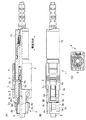
前記抜き治具付きプラグ1は、図1に示すように、嵌合相手方であるアダプタ側(図5参照)に設けられている弾性係止片15を、テーパ部2aで拡開させると共に段差部2bで係止させる係合部2cが、前記プラグ1の本体である合成樹脂製のプラグハウジング2の先端部で、その上下2箇所に設けられている。
【0011】
前記係合部2cに隣接する位置に、図1に示す例では両側に分かれた一対の係合部2c,2cの中間部に、係止解除片3aが設けられている。この係止解除片3aの上面が図1(A),(B)に示すように、前記係合部2c,2cの上面と同一面であり、半差し防止のため挿入力が変わらないようになっている。これは、前記弾性係止片15と係合部2cとの係止関係を解除するための係止片である。
【0012】
前記係止解除片3aの後端部に、前記弾性係止片15の係止作用を解除させるテーパ部3bが設けられていると共に、当該後端部から延設部3dが延設されていて、前記プラグハウジング2の外殻を囲繞して挿抜方向に沿って移動自在な抜去ツマミ3と前記係止解除片3aとが一体に形成されている。
【0013】
前記プラグハウジング2と抜去ツマミ3との間には、挿抜方向における相対的移動を規制する金属製又は合成樹脂製のストッパー手段であるストッパー4が設けられている。ストッパー4は、前記プラグハウジング2の上部に固着されており、その上部4aがプラグハウジング2の上面から突出し、抜去ツマミ3の上部開口部3cに遊嵌されるている。
【0014】
前記ストッパー4により、前記プラグ1を相手方のアダプタ8に嵌合させる際には、前記プラグハウジング2と抜去ツマミ3とが同時に挿入方向(図1において、左方向)に移動し、前記プラグ1をアダプタ8から抜去させる際には、抜去ツマミ3の係止解除片3aで弾性係止片15の係止作用を解除させた後に、前記プラグハウジング2と抜去ツマミ3とが同時に抜去方向(図1において右方向)に移動するように位置決めされる。
【0015】
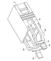
前記プラグハウジング2と抜去ツマミ3とは、図2乃至図4に示すように、合成樹脂製で形成されて、全体が矩形状で先端部が円筒状の嵌合部を有するプラグ框体1aとなるものである。
【0016】
なお、図1に示すように、符号5は光ファイバー接続用のフェルールを示し、符号6は、前記フェルール5を保持するフランジを示し、符号7は前記フランジ6を常に嵌合・接合方向に付勢するコイルバネを示している。前記ストッパー4の下部4bが、前記フランジ6の凹部6aに遊嵌状態で入り込んでいて、コイルバネ7によって付勢されるフランジ6が挿入方向へ抜け出すのを防止している。
【0017】
このように、ストッパー4は、フランジ6及びフェルール5の抜け出し防止部材を兼用している。よって、別途に抜出し防止部材を用意する必要がなく、部品点数を削減させてコスト低減となっている。また、組立時においては、プラグハウジング2と抜去ツマミ3とを嵌装させたストッパー4を半径方向の途中まで差し込んで仮組し、結線時に所望量押し込んで、フランジ6の挿抜方向の移動に差し支えないようにして、下部4bを凹部6aに遊嵌させるものである。
【0018】
このような本発明に係る抜き治具付きプラグ1により、相手方のアダプタ8に嵌合させ、または、抜去させる方法を説明する。まず、図5(A)に示すように嵌合時においては、挿入方向に抜去ツマミ3を押し込むと、開口部3cの片側壁面がストッパー4の上部4aに当接して、挿入方向の位置決めがされて、プラグハウジング2と抜去ツマミ3とが一緒に挿入方向に移動する。
【0019】
プラグハウジング2の先端部の係合部2cにおけるテーパ部2aが、弾性係止片15の係止部15aに摺接してこれを弾性力に抗して外側に拡開させる。
そして、図5(B)に示すように、前記係止部15aが、係合部2cの上面に乗り、そのまま移動する。係止解除片3aは、前記係合部2cとともに移動し、前記係止部15aの内側に入り込む。
【0020】
やがて、図5(C)に示すように、係止部15aが係合部2cの段差部2bに至ると、拡開された弾性反発力により内側に落ち込んで係止する。これにて、プラグ1の嵌合が完了する。
【0021】
次に、前記プラグ1をアダプタ8から抜去させる場合には、図6(A)に示すように、プラグ1の抜去ツマミ3を指で掴み抜去方向に引っ張る。前記抜去ツマミ3は、最初、図5(C)に示す状態から図6(A)に示す状態になり、プラグハウジング2に対して、抜去方向に移動している。開口部3cの右壁面がストッパー4の右側面に当接していたのが、開口部3cの左壁面がストッパー4の左側面に当接するようになったことで、明かである。
【0022】
前記抜去ツマミ3の抜去方向への移動で、係止解除片3aのテーパ部3bの作用により、アダプタ8側の弾性係止片15の係止部15aが、弾性力に抗して外側に拡開される。なお、プラグハウジング2は、段差部2bが係止部15aに係止されているので、抜去方向に移動できないものである。
【0023】
そして、図6(B)に示すように、抜去ツマミ3がストッパー4に当接するまで抜去方向に移動すると、係止部15aが外側に拡開されて前記段差部2bとの係止作用も解除される。よって、抜去ツマミ3を抜去方向に移動させると、ストッパー4で押されてプラグハウジング2も一緒に移動する。
【0024】
こうして、図6(C)に示すように、外側に拡開されていた係止部15aがテーパ部2aに沿って当接しながら弾性反発力で元の位置に戻り、プラグハウジング2と抜去ツマミ3とがアダプタ8から抜去される。前記抜去ツマミ3を、抜去方向に引くだけで、プラグ1をアダプタ8から抜去させることができるものである。
【0025】
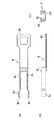
次に、本発明の他の実施例に係るもので、多数個のプラグが、例えば、格子状に密集して配設されて、格子状の中央部分のプラグに指が直接掛けられない場合があり、そのような場合に、抜去ツマミ3を間接的に引くことができるようにプルタブ9を使用する例である。
【0026】
前記プルタブ9は、図7乃至図8に示すように、全体が合成樹脂製で、先端側に抜去ツマミ3の外殻に被嵌されるカバー部9aと、係止突起9bとが設けられ、先端部から中央部にプラグ1のブーツ10に被嵌される取付部9cと、後端部に設けられるプル部9dとから構成されている。
【0027】
前記プルタブ9を、図8に示すように、抜去ツマミ3に前記係止突起9bを係止させて、プラグ1に装着するものである。この状態のまま、プラグ1を相手方のアダプタ8に嵌合させる。例えば、格子状に密集して配設されたプラグのうち、前記プラグ1を抜去させるには、指で掴むことのできる前記プルタブ9のプル部9dを掴んで、これを抜去方向に引くことで、抜去ツマミ3が引っ張られて、アダプタ8の弾性係止片15との係止作用が解除され、当該プラグ1がアダプタ8から、容易に抜去されるものである。
【0028】
以上のように、抜き治具付きプラグ1として説明したが、更に、図9に示すように、光伝送用の減衰器16として、フェルール5に減衰膜やフィルタ膜、減衰ファイバ等を組み込んで、光伝送路の途中に着脱自在に接続することができるものである。この減衰器16同士を首尾連接させることもできる。
【0029】
【発明の効果】
上記説明したように、本発明に係る抜き治具付きプラグは、アダプタに嵌合されるプラグにおいて、前記アダプタ側に設けられている弾性係止片をテーパ部で拡開させると共に段差部で係止させる一対の係合部が前記プラグの本体であるプラグハウジングの先端部に設けられ、前記一対の係合部の間に設けられる係止解除片であって、該係止解除片の上面が前記係合部の上面と同一面であり、その後端部にプラグ抜去時には前記弾性係止片の係止作用を解除させるテーパ部が設けられていると共に前記プラグハウジングを囲繞して挿抜方向に沿って移動自在な抜去ツマミに延設されて一体にされていて、前記プラグハウジングと抜去ツマミとの間にはストッパー手段が設けられ、当該ストッパー手段が前記プラグハウジングの上部に固着され、その上部が前記抜去ツマミの上部開口部に遊嵌されて挿抜方向における相対的移動を規制すると共に、その下部がフェルールを支持するフランジの凹部に遊嵌されて前記フェルールと前記フランジとの挿入方向への抜出しを防止しており、当該ストッパー手段により、前記プラグの前記抜去ツマミを持ってアダプタに嵌合させる際には、前記抜去ツマミの上部開口部に遊嵌されている前記ストッパー手段の上部に当該上部開口部の片側壁面が当接して、前記プラグハウジングと抜去ツマミとが同時に挿入方向に移動するように位置決めされるとともに、前記プラグをアダプタから抜去させる際には、抜去ツマミがその上部開口部に遊嵌されている前記ストッパー手段に当接するまで抜去方向に移動して、当該抜去ツマミの係止解除片で前記アダプタ側の弾性係止片の係止作用を解除させた後に、前記ストッパー手段を介して前記プラグハウジングと抜去ツマミとが同時に抜去方向に移動するように位置決めされるいるので、前記抜去ツマミを掴んで抜去方向に引くだけで、プラグをアダプタから抜くことができて、一度の操作で容易にプラグを抜去させることができると言う優れた効果を奏するものである。また、係止解除片が抜去ツマミに一体に形成されてプラグの部品高さが嵩張らないので、高密度実装に適している。また、該係止解除片の上面が前記係合部の上面と同一面なので挿入力が変わらず半差しが防止される。更に、専用の抜き治具に較べて部品点数が少なく、合成樹脂製で一体物として低コストで製作することができる。
【0030】
また、前記ストッパー手段により、プラグの嵌合及び嵌合係止解除が確実に行われ、挿抜作用がスムーズに行われる。
【0031】
ストッパーは、フランジ及びフェルールの抜け出し防止部材を兼用しているので、別途に抜出し防止部材を用意する必要がなく、部品点数を削減させてコスト低減となっている。
【図面の簡単な説明】
【図1】本発明に係る抜き治具付きプラグ1の一部を半断面にして示す正面図(A)、同平面図(B)、側面図(C)である。
【図2】同本発明に係る抜き治具付きプラグ1のプラグ框体1aの斜視図である。
【図3】同本発明に係る抜き治具付きプラグ1におけるプラグハウジング2の斜視図である。
【図4】同本発明に係る抜き治具付きプラグ1における抜去ツマミ3の斜視図である。
【図5】同本発明に係る抜き治具付きプラグ1の嵌合時の説明図(A),(B),(C)である。
【図6】同本発明に係る抜き治具付きプラグ1の抜去時の説明図(A),(B),(C)である。
【図7】プルタブ9の平面図(A)、同正面図(B)、側面図(C)である。
【図8】本発明に係る抜き治具付きプラグ1にプルタブ9を装着した際の、平面図(A)、正面図(B)、側面図(C)である。
【図9】抜け治具を減衰器16に適用した例の、平断面図(A)、正面図(B)、左右側面図(C),(D)である。
【符号の説明】
1 抜き治具付きプラグ、 2 プラグハウジング、
2a テーパ部、 2b 段差部、
2c 係合部、 3 抜去ツマミ、
3a 係止解除片、 3b テーパ部、
3c 開口部、 4 ストッパー、
5 フェルール、 6 フランジ、
7 コイルバネ、 8 アダプタ、
9 プルタブ、 9a カバー部、
9b 係止突起、 9c 取付部、
9d プル部、 10 ブーツ、
15 弾性係止片、 15a 係止部、
16 減衰器。[0001]
BACKGROUND OF THE INVENTION
The present invention relates to a plug with a removal jig. More specifically, the present invention relates to a plug with a removal jig that facilitates easy removal of a plug that is mainly fitted to an optical fiber connector and further increases the mounting density.
[0002]
[Prior art]
2. Description of the Related Art Conventionally, a plug for a cable that is fitted to an SC type optical connector, for example, an optical fiber connector, is not heightened by removing plug removal parts in order to increase the mounting density. .
[0003]
Therefore, in order to remove the fitted plug from the connector, a separate dedicated tool is required, which is inconvenient in terms of convenience. Therefore, a plug with a removal jig has been proposed and known (for example, see Patent Document 1).
[0004]
[Patent Document 1]
Utility Model Registration No. 2579870 (page 2-4, Fig. 1)
[0005]
[Problems to be solved by the invention]
However, even in this case, in order to extract the plug from the adapter, (1) push the extraction jig in the direction opposite to the extraction direction, release the adapter lock, (2) pull the plug while maintaining the state, A two-action extraction operation is required to extract from the adapter. In addition, the punching jig portion is composed of a large number of parts, which requires a large number of assembly steps and increases manufacturing costs. The plug with a removal jig according to the present invention has been proposed to solve such a problem.
[0006]
[Means for Solving the Problems]
In order to solve the above-mentioned problems, the gist of the plug with a removal jig according to the present invention is to expand the elastic locking piece provided on the adapter side at the taper portion in the plug fitted to the adapter. A pair of engaging portions to be locked by the stepped portion is provided at the tip end portion of the plug housing which is the main body of the plug, and is an unlocking piece provided between the pair of engaging portions, the unlocking The upper surface of the piece is flush with the upper surface of the engaging portion, and a taper portion is provided at the rear end portion for releasing the locking action of the elastic locking piece when the plug is removed, and surrounds the plug housing. It is extended and integrated with an extraction knob that is movable along the insertion / extraction direction,
Stopper means is provided between the plug housing and the removal knob, and the stopper means is fixed to the upper part of the plug housing, and the upper part is loosely fitted into the upper opening of the removal knob, so that it is relatively inserted in the insertion / removal direction. While restricting the movement, the lower part is loosely fitted in the concave part of the flange supporting the ferrule to prevent the ferrule and the flange from being pulled out in the insertion direction,
By the stopper means
When fitting the adapter with the removal knob of the plug,
One side wall surface of the upper opening is in contact with the upper part of the stopper means loosely fitted in the upper opening of the extraction knob,
The plug housing and the removal knob are positioned so as to move simultaneously in the insertion direction,
When removing the plug from the adapter,
Move in the extraction direction until the extraction knob comes into contact with the stopper means loosely fitted in the upper opening,
After releasing the locking action of the elastic locking piece on the adapter side with the locking release piece of the extraction knob, positioning is performed so that the plug housing and the extraction knob simultaneously move in the extraction direction via the stopper means. It is to be done .
[0008]
According to the plug with the extraction jig according to the present invention, the plug housing can be extracted from the adapter only by pulling the extraction knob integral with the locking release piece in the extraction direction of the insertion / extraction direction. Further, the plug housing is smoothly inserted into and removed from the adapter by the stopper means for restricting relative movement between the removal knob and the plug housing .
[0009]
DETAILED DESCRIPTION OF THE INVENTION
Next, the
[0010]
As shown in FIG. 1, the
[0011]
At a position adjacent to the
[0012]
A
[0013]
Between the
[0014]
When the
[0015]
As shown in FIGS. 2 to 4, the
[0016]
As shown in FIG. 1,
[0017]
Thus, the
[0018]
A description will be given of a method of fitting to or removing from the
[0019]
The
Then, as shown in FIG. 5B, the locking
[0020]
Eventually, as shown in FIG. 5 (C), when the locking
[0021]
Next, when the
[0022]
By the movement of the
[0023]
Then, as shown in FIG. 6 (B), when the
[0024]
Thus, as shown in FIG. 6 (C), the locking
[0025]
Next, according to another embodiment of the present invention, there are cases where a large number of plugs are densely arranged, for example, in a lattice shape, and a finger cannot be directly hung on the plug in the central portion of the lattice shape. There is an example in which the
[0026]
As shown in FIGS. 7 to 8, the
[0027]
As shown in FIG. 8, the
[0028]
As described above, the
[0029]
【The invention's effect】
As described above, in the plug with a removal jig according to the present invention, in the plug fitted to the adapter, the elastic locking piece provided on the adapter side is expanded at the taper portion and is engaged at the step portion. A pair of engaging portions to be stopped is provided at a distal end portion of a plug housing which is a main body of the plug, and is an unlocking piece provided between the pair of engaging portions, and an upper surface of the locking release piece is It is flush with the upper surface of the engaging portion, and a taper portion is provided at the rear end portion for releasing the locking action of the elastic locking piece when the plug is pulled out. have been integrally extends in the movable removal knob Te, the stopper means between the plug housing and the removal knob is provided, said stopper means is fixed to an upper portion of the plug housing The upper part is loosely fitted in the upper opening of the removal knob to restrict relative movement in the insertion / removal direction, and the lower part is loosely fitted in the concave part of the flange supporting the ferrule so that the insertion direction of the ferrule and the flange is When the stopper means is used to hold the extraction knob of the plug and is fitted to the adapter, the upper portion of the stopper means is loosely fitted in the upper opening of the extraction knob. The one side wall surface of the upper opening abuts and is positioned so that the plug housing and the removal knob move in the insertion direction at the same time, and when the plug is removed from the adapter, the removal knob It moves in the removal direction until it comes into contact with the stopper means loosely fitted in the opening, and the unlocking piece of the removal knob After allowed to release the locking action of the adapter side of the elastic locking piece, since the said plug housing and removal knob through said stopper means is positioned to move in removing direction simultaneously, grabbing the removal knob By simply pulling in the removal direction, the plug can be removed from the adapter, and an excellent effect is obtained that the plug can be easily removed by a single operation. Further, since the unlocking piece is formed integrally with the removal knob and the height of the plug part is not bulky, it is suitable for high-density mounting. Further, since the upper surface of the unlocking piece is flush with the upper surface of the engaging portion, the insertion force does not change and half insertion is prevented. Furthermore, the number of parts is smaller than that of a dedicated punching jig, and it can be manufactured at a low cost as a single unit made of synthetic resin.
[0030]
Further, the stopper means ensures that the plug is fitted and unlocked, and the insertion / extraction action is performed smoothly.
[0031]
Since the stopper also serves as a flange and ferrule pull-out prevention member, it is not necessary to prepare a separate pull-out prevention member, reducing the number of parts and reducing the cost.
[Brief description of the drawings]
FIG. 1 is a front view (A), a plan view (B), and a side view (C) showing a part of a
FIG. 2 is a perspective view of a
FIG. 3 is a perspective view of a
FIG. 4 is a perspective view of a
FIGS. 5A and 5B are explanatory views (A), (B), and (C) when the
FIGS. 6A and 6B are explanatory views (A), (B), and (C) at the time of removing the
7 is a plan view (A), a front view (B), and a side view (C) of the
FIG. 8 is a plan view (A), a front view (B), and a side view (C) when the
FIG. 9 is a cross-sectional view (A), a front view (B), and left and right side views (C) and (D) of an example in which the removal jig is applied to the
[Explanation of symbols]
1 Plug with extraction jig, 2 Plug housing,
2a taper part, 2b step part,
2c engaging part, 3 extraction knob,
3a unlocking piece, 3b taper part,
3c opening, 4 stopper,
5 Ferrule, 6 Flange,
7 Coil spring, 8 Adapter,
9 Pull tab, 9a Cover part,
9b Locking projection, 9c Mounting part,
9d pull section, 10 boots,
15 elastic locking piece, 15a locking part,
16 Attenuator.
Claims (1)
前記プラグハウジングと抜去ツマミとの間にはストッパー手段が設けられ、当該ストッパー手段が前記プラグハウジングの上部に固着され、その上部が前記抜去ツマミの上部開口部に遊嵌されて挿抜方向における相対的移動を規制すると共に、その下部がフェルールを支持するフランジの凹部に遊嵌されて前記フェルールと前記フランジとの挿入方向への抜出しを防止しており、
当該ストッパー手段により、
前記プラグの前記抜去ツマミを持ってアダプタに嵌合させる際には、
前記抜去ツマミの上部開口部に遊嵌されている前記ストッパー手段の上部に当該上部開口部の片側壁面が当接して、
前記プラグハウジングと抜去ツマミとが同時に挿入方向に移動するように位置決めされるとともに、
前記プラグをアダプタから抜去させる際には、
抜去ツマミがその上部開口部に遊嵌されている前記ストッパー手段に当接するまで抜去方向に移動して、
当該抜去ツマミの係止解除片で前記アダプタ側の弾性係止片の係止作用を解除させた後に、前記ストッパー手段を介して前記プラグハウジングと抜去ツマミとが同時に抜去方向に移動するように位置決めされること、
を特徴とする抜き治具付きプラグ。In the plug fitted to the adapter, a pair of engaging portions for expanding the elastic locking piece provided on the adapter side at the taper portion and locking at the stepped portion is a plug housing which is the main body of the plug. An unlocking piece provided between the pair of engaging portions, provided at the distal end portion, the upper surface of the unlocking piece being flush with the upper surface of the engaging portion, and a plug at the rear end portion A taper portion for releasing the locking action of the elastic locking piece at the time of extraction is provided, and the plug housing is extended and integrated with an extraction knob that is movable along the insertion / extraction direction,
Stopper means is provided between the plug housing and the removal knob, and the stopper means is fixed to the upper part of the plug housing, and the upper part is loosely fitted into the upper opening of the removal knob, so that it is relatively inserted in the insertion / removal direction. While restricting the movement, the lower part is loosely fitted in the concave part of the flange supporting the ferrule to prevent the ferrule and the flange from being pulled out in the insertion direction,
By the stopper means
When fitting the adapter with the removal knob of the plug,
One side wall surface of the upper opening is in contact with the upper part of the stopper means loosely fitted in the upper opening of the extraction knob,
The plug housing and the removal knob are positioned so as to move simultaneously in the insertion direction,
When removing the plug from the adapter,
Move in the extraction direction until the extraction knob comes into contact with the stopper means loosely fitted in the upper opening,
After releasing the locking action of the elastic locking piece on the adapter side with the locking release piece of the extraction knob, positioning is performed so that the plug housing and the extraction knob simultaneously move in the extraction direction via the stopper means. Being
A plug with a removal jig characterized by
Priority Applications (1)
| Application Number | Priority Date | Filing Date | Title |
|---|---|---|---|
| JP2003181175A JP4215577B2 (en) | 2003-06-25 | 2003-06-25 | Plug with extraction jig |
Applications Claiming Priority (1)
| Application Number | Priority Date | Filing Date | Title |
|---|---|---|---|
| JP2003181175A JP4215577B2 (en) | 2003-06-25 | 2003-06-25 | Plug with extraction jig |
Related Child Applications (1)
| Application Number | Title | Priority Date | Filing Date |
|---|---|---|---|
| JP2008229525A Division JP4783820B2 (en) | 2008-09-08 | 2008-09-08 | Plug with extraction jig |
Publications (2)
| Publication Number | Publication Date |
|---|---|
| JP2005017602A JP2005017602A (en) | 2005-01-20 |
| JP4215577B2 true JP4215577B2 (en) | 2009-01-28 |
Family
ID=34181945
Family Applications (1)
| Application Number | Title | Priority Date | Filing Date |
|---|---|---|---|
| JP2003181175A Expired - Fee Related JP4215577B2 (en) | 2003-06-25 | 2003-06-25 | Plug with extraction jig |
Country Status (1)
| Country | Link |
|---|---|
| JP (1) | JP4215577B2 (en) |
Families Citing this family (11)
| Publication number | Priority date | Publication date | Assignee | Title |
|---|---|---|---|---|
| EP1762870A1 (en) * | 2005-09-12 | 2007-03-14 | Reichle & De-Massari AG | Secured connector system |
| JP4726737B2 (en) | 2006-08-16 | 2011-07-20 | 富士通株式会社 | Auxiliary release releasing device for optical connector and printed circuit board device |
| JP4776504B2 (en) | 2006-11-15 | 2011-09-21 | 富士通株式会社 | Auxiliary release releasing device for optical connector and printed circuit board device |
| JP4767154B2 (en) | 2006-11-15 | 2011-09-07 | 富士通株式会社 | Auxiliary release releasing device for optical connector and printed circuit board device |
| JP5182893B2 (en) * | 2009-11-17 | 2013-04-17 | Nttエレクトロニクス株式会社 | Optical connector plug |
| JP6118882B1 (en) * | 2015-11-16 | 2017-04-19 | 株式会社フジクラ | Optical connector |
| CN106207563B (en) * | 2016-08-31 | 2019-03-26 | 维尔斯电子(昆山)有限公司 | A kind of self-locking plug adapter and power supply line |
| US10228521B2 (en) * | 2016-12-05 | 2019-03-12 | Senko Advanced Components, Inc. | Narrow width adapters and connectors with modular latching arm |
| US9958623B1 (en) | 2017-06-29 | 2018-05-01 | Seikoh Giken Co., Ltd. | Tool for plug, plug and cable with plug |
| JP7208623B2 (en) | 2019-03-04 | 2023-01-19 | 株式会社精工技研 | Tools for plugs and plugs and cables with plugs |
| JP6812037B1 (en) * | 2020-03-05 | 2021-01-13 | 株式会社精工技研 | Jig for connector plug, connector plug, cable with connector plug |
Family Cites Families (1)
| Publication number | Priority date | Publication date | Assignee | Title |
|---|---|---|---|---|
| JP3362014B2 (en) * | 1999-06-29 | 2003-01-07 | エヌイーシートーキン株式会社 | Lock and unlock structure of cable connector and method of locking and unlocking |
-
2003
- 2003-06-25 JP JP2003181175A patent/JP4215577B2/en not_active Expired - Fee Related
Also Published As
| Publication number | Publication date |
|---|---|
| JP2005017602A (en) | 2005-01-20 |
Similar Documents
| Publication | Publication Date | Title |
|---|---|---|
| JP3362014B2 (en) | Lock and unlock structure of cable connector and method of locking and unlocking | |
| JP4215577B2 (en) | Plug with extraction jig | |
| JPH089913Y2 (en) | connector | |
| JP2682554B2 (en) | Connector locking mechanism | |
| JPH0794230A (en) | Connector | |
| JP2002246110A (en) | Connector | |
| JP2001319731A (en) | Connecting device, connecting plug, connecting jack | |
| JP3651311B2 (en) | Optical connector | |
| JP2001160448A (en) | Connector | |
| JP4783820B2 (en) | Plug with extraction jig | |
| JP2990740B2 (en) | Optical connector | |
| JPH07249454A (en) | Connector | |
| JP5329339B2 (en) | connector | |
| JP3687537B2 (en) | Split connector | |
| JP2004079206A (en) | Connector | |
| JP4306573B2 (en) | connector | |
| JP4158898B2 (en) | Connector and its connector attaching / detaching tool | |
| JP2001160447A (en) | Connector | |
| JPH0312232Y2 (en) | ||
| JP3495701B2 (en) | Connector device | |
| JP4258146B2 (en) | connector | |
| KR100941829B1 (en) | Automobile Connecter | |
| JP2615310B2 (en) | Electrical connector with terminal lock | |
| JP4371021B2 (en) | connector | |
| JPH0142311Y2 (en) |
Legal Events
| Date | Code | Title | Description |
|---|---|---|---|
| A621 | Written request for application examination |
Free format text: JAPANESE INTERMEDIATE CODE: A621 Effective date: 20051014 |
|
| A977 | Report on retrieval |
Free format text: JAPANESE INTERMEDIATE CODE: A971007 Effective date: 20080124 |
|
| A131 | Notification of reasons for refusal |
Free format text: JAPANESE INTERMEDIATE CODE: A131 Effective date: 20080130 |
|
| A521 | Written amendment |
Free format text: JAPANESE INTERMEDIATE CODE: A523 Effective date: 20080317 |
|
| A131 | Notification of reasons for refusal |
Free format text: JAPANESE INTERMEDIATE CODE: A131 Effective date: 20080414 |
|
| A521 | Written amendment |
Free format text: JAPANESE INTERMEDIATE CODE: A523 Effective date: 20080612 |
|
| A02 | Decision of refusal |
Free format text: JAPANESE INTERMEDIATE CODE: A02 Effective date: 20080708 |
|
| A521 | Written amendment |
Free format text: JAPANESE INTERMEDIATE CODE: A523 Effective date: 20080908 |
|
| A521 | Written amendment |
Free format text: JAPANESE INTERMEDIATE CODE: A523 Effective date: 20080908 |
|
| A911 | Transfer of reconsideration by examiner before appeal (zenchi) |
Free format text: JAPANESE INTERMEDIATE CODE: A911 Effective date: 20080919 |
|
| TRDD | Decision of grant or rejection written | ||
| A01 | Written decision to grant a patent or to grant a registration (utility model) |
Free format text: JAPANESE INTERMEDIATE CODE: A01 Effective date: 20081009 |
|
| A01 | Written decision to grant a patent or to grant a registration (utility model) |
Free format text: JAPANESE INTERMEDIATE CODE: A01 |
|
| A61 | First payment of annual fees (during grant procedure) |
Free format text: JAPANESE INTERMEDIATE CODE: A61 Effective date: 20081104 |
|
| R150 | Certificate of patent or registration of utility model |
Free format text: JAPANESE INTERMEDIATE CODE: R150 |
|
| FPAY | Renewal fee payment (event date is renewal date of database) |
Free format text: PAYMENT UNTIL: 20111114 Year of fee payment: 3 |
|
| FPAY | Renewal fee payment (event date is renewal date of database) |
Free format text: PAYMENT UNTIL: 20121114 Year of fee payment: 4 |
|
| FPAY | Renewal fee payment (event date is renewal date of database) |
Free format text: PAYMENT UNTIL: 20121114 Year of fee payment: 4 |
|
| FPAY | Renewal fee payment (event date is renewal date of database) |
Free format text: PAYMENT UNTIL: 20131114 Year of fee payment: 5 |
|
| LAPS | Cancellation because of no payment of annual fees |