JP4214919B2 - Storage switch with bandwidth control function - Google Patents
Storage switch with bandwidth control function Download PDFInfo
- Publication number
- JP4214919B2 JP4214919B2 JP2004008619A JP2004008619A JP4214919B2 JP 4214919 B2 JP4214919 B2 JP 4214919B2 JP 2004008619 A JP2004008619 A JP 2004008619A JP 2004008619 A JP2004008619 A JP 2004008619A JP 4214919 B2 JP4214919 B2 JP 4214919B2
- Authority
- JP
- Japan
- Prior art keywords
- packet
- data
- user
- unit
- transfer
- Prior art date
- Legal status (The legal status is an assumption and is not a legal conclusion. Google has not performed a legal analysis and makes no representation as to the accuracy of the status listed.)
- Expired - Fee Related
Links
Images


Classifications
-
- H—ELECTRICITY
- H04—ELECTRIC COMMUNICATION TECHNIQUE
- H04L—TRANSMISSION OF DIGITAL INFORMATION, e.g. TELEGRAPHIC COMMUNICATION
- H04L49/00—Packet switching elements
- H04L49/20—Support for services
- H04L49/205—Quality of Service based
-
- H—ELECTRICITY
- H04—ELECTRIC COMMUNICATION TECHNIQUE
- H04L—TRANSMISSION OF DIGITAL INFORMATION, e.g. TELEGRAPHIC COMMUNICATION
- H04L49/00—Packet switching elements
- H04L49/35—Switches specially adapted for specific applications
-
- H—ELECTRICITY
- H04—ELECTRIC COMMUNICATION TECHNIQUE
- H04L—TRANSMISSION OF DIGITAL INFORMATION, e.g. TELEGRAPHIC COMMUNICATION
- H04L67/00—Network arrangements or protocols for supporting network services or applications
- H04L67/01—Protocols
- H04L67/10—Protocols in which an application is distributed across nodes in the network
- H04L67/1097—Protocols in which an application is distributed across nodes in the network for distributed storage of data in networks, e.g. transport arrangements for network file system [NFS], storage area networks [SAN] or network attached storage [NAS]
-
- H—ELECTRICITY
- H04—ELECTRIC COMMUNICATION TECHNIQUE
- H04L—TRANSMISSION OF DIGITAL INFORMATION, e.g. TELEGRAPHIC COMMUNICATION
- H04L69/00—Network arrangements, protocols or services independent of the application payload and not provided for in the other groups of this subclass
- H04L69/30—Definitions, standards or architectural aspects of layered protocol stacks
- H04L69/32—Architecture of open systems interconnection [OSI] 7-layer type protocol stacks, e.g. the interfaces between the data link level and the physical level
- H04L69/322—Intralayer communication protocols among peer entities or protocol data unit [PDU] definitions
- H04L69/329—Intralayer communication protocols among peer entities or protocol data unit [PDU] definitions in the application layer [OSI layer 7]
Abstract
Description
本発明は、ストレージデータの転送帯域を成形する帯域制御機能を有するストレージスイッチに関する。 The present invention relates to a storage switch having a bandwidth control function for shaping a storage data transfer bandwidth.
iSCSIは、パーソナルコンピュータとストレージ装置などの周辺機器を接続する規格であるSCSI(Small Computer System Interface)コマンドをTCP/IP(Transmission Control Protocol/Internet Protocol)でカプセリングする規格である。iSCSIを用いることでユーザはIPネットワーク上のiSCSIに対応するストレージ装置などの周辺機器(以下:ストレージ装置とするが、iSCSIに対応する装置なら何でも良い)へSCSIコマンドを利用してアクセス(データの読み出しRD(Read)、書き込みWR(Write)処理など)を行うことが出来る。ここではコマンドを発行する装置をイニシエータ、コマンドを受けてそのコマンドが要求する処理を行う装置をターゲットと呼ぶ。また、ここではiSCSIコマンドを含むIPパケットをiSCSIパケットと呼ぶことにする。 iSCSI is a standard for encapsulating Small Computer System Interface (SCSI) commands, which are standards for connecting personal computers and peripheral devices such as storage devices, using TCP / IP (Transmission Control Protocol / Internet Protocol). By using iSCSI, users can access peripheral devices such as storage devices that support iSCSI on the IP network (hereinafter referred to as storage devices, but any device that supports iSCSI) using SCSI commands (data Read RD (Read), write WR (Write) processing, etc.). Here, a device that issues a command is called an initiator, and a device that receives a command and performs processing requested by the command is called a target. Here, an IP packet including an iSCSI command is called an iSCSI packet.
例えば、図1は、遠隔地にいるユーザ100−i(i=1〜n)がユーザごとに帯域が保証されているIPネットワークもしくは広域イーサネット(登録商標)などで構築された広域ネットワーク網102を利用してデータセンタ103へiSCSIを利用してアクセスするアプリケーションを表している。データセンタ103内部はストレージスイッチ104とストレージ装置105−i(i=1〜n)によりIP−SANまたはFC−SAN(以下IP−SAN、FC−SANの総称としてSANを使用)106が構築されている。管理コンソール107はストレージスイッチ104の設定を行う。ユーザ100とデータセンタ103を結ぶ広域ネットワーク網102は帯域保証サービスにより保証されており、トラヒック量が契約帯域内の場合は途中でデータの廃棄は発生しない。
For example, FIG. 1 shows a case where a user 100-i (i = 1 to n) in a remote location has a
広域ネットワーク網102でのQoS(Quality of Service)制御には、網の入り口部のパケット転送装置101にてユーザが契約帯域内でデータの送受信を行っているか否かを監視するUPC(User Parameter Control)機能を利用することが一般的である。QoS制御とは、ベストエフォートが主流なIPネットワークにおいて、ユーザ毎に設定した通信帯域を保証する技術である。UPCは契約帯域を越えるトラヒックを検知した場合は、その場で違反パケットを廃棄するか、広域ネットワーク網内で輻輳が発生した時に廃棄の対象とするために転送優先度を低く設定する、等の転送優先制御を行う。
For QoS (Quality of Service) control in the
図2は図1のアプリケーション例においてユーザ100からデータセンタ103内のストレージ装置105−iへ対してデータのRDを行った場合の概念図を示す。ユーザとストレージ装置は簡単化のため1体ずつとし、他は省略している。図2を用いてストレージ装置105−iからのデータ読み出し方法を説明する。まずユーザ100はストレージ装置105−iへデータを要求するため、iSCSIコマンドのデータRD要求(正確にはiSCSI PDU(Protocol Data Unit)のBHS(Basic Header Segment)のオペコードが0x01で、Rbitに1が設定されているiSCSIパケットのこと(以下RD(Read)要求パケット)) を送信する。RD要求パケット200にはユーザが要求するデータのデータ容量(正確にはオペコードが0x01で、Rbitに1が設定されているBHSのExpected Data Transfer Lengthの値(以下要求RD長))が含まれている。RD要求パケット200を受信したストレージ装置105−iはユーザ100へ向けて要求RD長分のデータをiSCSI パケットのデータインコマンド(正確にはiSCSI PDUのBHSのオペコードが0x25のSCSI Data−in(以下RDデータパケット))201を利用してユーザへ送信する。RDデータがネットワークの経路MTU(Maximum Transfer Unit)を超える場合は複数のRDデータパケットに分割され転送される。以上がデータの読み出しの一連の流れとなる。
FIG. 2 is a conceptual diagram when data RD is performed from the
1つのRD要求パケット200のデータ容量は100バイト程度と小さい。一方RDデータパケット201のデータサイズはユーザが要求するデータ量により異なるが、数十キロバイト〜数百キロバイト以上となることが多い。このため、ユーザ100がストレージ装置105−iへ送信するRD要求パケット200のトラヒック量は契約帯域内であっても、ストレージ装置105−iがユーザ100へ送信するRDデータパケット201のトラヒック量がユーザ契約帯域違反となる可能性がある。契約帯域違反となったRDデータパケット201は、広域ネットワーク網内の輻輳スポットで帯域違反による廃棄202や、パケット転送装置101でのQoS制御による廃棄203などによりユーザ100へ到達できなくなる。
The data capacity of one
図3は図1のアプリケーション例においてユーザ100からデータセンタ103内のストレージ装置105−iへ対してデータのWR(Write)を行った場合の概念図を示す。ユーザとストレージ装置は簡単化のため1体ずつとし、他は省略している。iSCSIを用いたストレージ装置105−iへのデータ書き込み方法を説明する。まず、ユーザ100はストレージ装置105−iへデータの書き込みを要求するため、iSCSI コマンドのデータWR要求(正確にはiSCSI PDUのBHSのオペコードが0x01で、Wbitに1が設定されているiSCSIパケットのこと(以下WR(Write)要求パケット))を送信する。WR要求パケット300を受信したストレージ装置105−iはユーザ100へ向けてiSCSI パケットのR2Tコマンド(正確にはiSCSI PDUのBHSのオペコードが0x31のReady to Transfer(以下R2Tパケット))301を送信する。R2Tパケット 301はストレージ装置105−iがユーザ100から送信されるデータの書き込み準備が完了したことをユーザ100に示す役割を持つ。R2Tパケット301には一度に受け入れられるデータ量が何バイトであるかの情報(正確にはR2TのDesired Data Transfer Lengthの値(以下要求WR長))が入っている。R2Tパケット 301を受信したユーザ100はストレージ装置105−iへ向けてR2Tパケット 301の要求WR長分のデータをiSCSIパケットのデータアウトコマンド(正確にはiSCSI PDUのBHSのオペコードが0x05のSCSI Data−out(以下WRデータパケット))302を利用して送信する。WRデータがネットワークの経路MTUを超える場合は複数のWRデータパケットに分割され転送される。以上がデータWRの一連の流れとなる。
FIG. 3 is a conceptual diagram when data WR (Write) is performed from the
RDの場合と同様、WRデータパケット302のデータサイズとWR要求パケット300、R2Tパケット 301のデータサイズには大きな差がある。このためユーザ100がストレージ装置105−iへ送信するWR要求パケット300及びストレージ装置105−iがユーザ100へ送信するR2Tパケット 301のトラヒック量はユーザ契約帯域に収まるが、ユーザ100がストレージ装置105−iへ送信するWRデータパケット302のトラヒック量はユーザ契約帯域違反となる可能性がある。契約帯域違反となったWRデータパケット302は、広域ネットワーク網内の輻輳スポットで帯域違反による廃棄303や、パケット転送装置101でのQoS制御による廃棄304などによりストレージ装置105−iへ到達できなくなる。
As in the case of RD, there is a large difference between the data size of the
iSCSIは上位プロトコルにTCP/IPを用いる。そのため、途中経路でデータの廃棄が発生した場合は、再送制御が行われる。しかし、廃棄量が多くなると、広域ネットワーク網102での無駄なトラヒックの発生、ストレージスイッチ104およびストレージ装置105−iの無駄なリソース消費に繋がり装置全体の性能を劣化させる原因となる。
広域ネットワーク網102での送信データ帯域がユーザ契約帯域を越えないようにするために、従来からのIPネットワークでは、広域ネットワーク網の入り口にトラヒックシェーパという帯域制御機能を設置する必要があった。トラヒックシェーパはユーザが広域ネットワークへ送出するデータ量が契約帯域を超えないようにトラヒックを制御(シェーピング)し、広域ネットワーク網102内での送信データの廃棄を回避する。広域ネットワーク網102へ契約帯域以上のデータが転送されないように保証する帯域制御装置の特許として、例えば特許文献1がある。特許文献1で開示されている帯域制御装置は、ユーザから送出されるパケットを一旦帯域制御装置内部のバッファへ格納する。次に、バッファからのパケット読み出し量を常に計測して契約帯域を越えるパケット量をバッファから読み出した場合、バッファからのパケット読み出しを一時的に中断することでユーザから広域ネットワークへ送信するデータ量が契約帯域を超えないようにコントロールする。
iSCSI uses TCP / IP as the upper protocol. Therefore, when data is discarded on the way, retransmission control is performed. However, an increase in the amount of discard leads to generation of useless traffic in the
In order to prevent the transmission data band in the
特許文献1の帯域制御装置を図1で示すネットワークへ適用すると、3つ問題点がある。第一の問題点は、RDデータパケットおよびWRデータパケットが一時に大量に発生し(このような状況を以下、バーストという)、帯域制御装置に入力した場合はバッファがオーバーフローし、データを廃棄する点である。ストレージデータは、従来からIPネットワークで送受信されているデータにくらべ、大容量でかつバースト性を持つ特徴がある。このため、RDデータパケット201、WRデータパケット302を廃棄させること無く帯域制御を行うためには、トラヒックシェーパは数メガバイトから数10メガバイト程度の大容量なバッファをユーザ毎に確保する必要がある。このように大容量なバッファ領域をユーザごとに確保することは物理的に非常に厳しく、実現出来たとしても拡張性は非常に乏しい。
When the bandwidth control device of
第二の問題点は、ストレージ装置105−iおよびユーザのコンピュータ端末へ必要以上の負荷が掛かる点である。特許文献1の帯域制御装置では、広域ネットワークへ送出するデータ量が契約帯域内であるか否かだけを確認してパケットを送出する。RD要求パケット200、R2Tパケット 301には送信要求データ長情報が含まれている。これらiSCSIパケットを受けたユーザのコンピュータ端末、ストレージ装置105−iはデータの送出量が契約帯域内であるか否かに関わらずバースト的にデータの転送を行う。広域ネットワーク網の契約帯域以上のデータをバーストで読み出しても帯域制御装置で遅延させられるか、もしくは廃棄される。そのため、広域ネットワーク網の契約帯域以上のデータ読み出しはストレージ装置105−iおよびユーザのコンピュータ端末のリソースの無駄な消費に繋がる。
The second problem is that an unnecessary load is applied to the storage apparatus 105-i and the user's computer terminal. In the bandwidth control device of
第三の問題点は、RDデータパケット201はストレージ装置105−i側、WRデータパケット302はユーザ100側で帯域制御を行う必要があった。そのため、ストレージ装置105−i側、ユーザ100側両方に帯域制御装置が必要となる点である。
以上述べたように従来のIPネットワークの帯域制御装置では、ストレージデータの帯域を効率よく制御し、ストレージ装置およびユーザのコンピュータ端末の無駄なリソース消費を防止することが出来なかった。
本発明の目的は、大容量なバッファを必要とせず、拡張性に優れ、契約帯域以上の無駄なデータ送出をユーザ端末およびストレージ装置にもたらさない帯域制御を、ストレージ装置側ネットワークに用意するだけで可能とすることを提供することである。
The third problem is that the RD data packet 201 needs to be band-controlled on the storage device 105-i side, and the
As described above, the bandwidth control device of the conventional IP network cannot efficiently control the storage data bandwidth and prevent wasteful resource consumption of the storage device and the user's computer terminal.
The object of the present invention is to provide a storage device side network with bandwidth control that does not require a large-capacity buffer, has excellent expandability, and does not cause unnecessary data transmission beyond the contracted bandwidth to the user terminal and storage device. It is to provide what is possible.
上記目的を達成するために、本発明の帯域制御機能を有するストレージスイッチはRD要求パケット内にある要求RD長から該RD要求パケットをターゲットへ転送した場合ターゲットがネットワークへと送信するRDデータ量を予測して帯域制御を行う。また同様に、R2Tパケット内にある要求WR長から該R2Tパケットをイニシエータへ転送した場合イニシエータがネットワークへ送信するWRデータ量を予測して帯域制御を行う。
上記以外の本願が解決しようとする課題、その解決手段は、本願の「発明を実施するための最良の形態」の欄および図面で明らかにされる。
In order to achieve the above object, the storage switch having the bandwidth control function according to the present invention reduces the amount of RD data transmitted from the target to the network when the RD request packet is transferred from the request RD length in the RD request packet to the target. Predict and perform bandwidth control. Similarly, when the R2T packet is transferred to the initiator from the request WR length in the R2T packet, the bandwidth control is performed by predicting the amount of WR data transmitted from the initiator to the network.
Problems other than those described above and problems to be solved by the present application will be clarified in the "Best Mode for Carrying Out the Invention" column and drawings of the present application.
本発明によれば、RDデータパケットやWRデータパケットをバッファリングして帯域制御を行う従来の帯域制御装置のように大容量なバッファを必要としない。また、大容量バッファを必要としないため拡張性に優れる。また、ストレージ装置及びユーザのコンピュータ端末へ、広域ネットワーク網の契約帯域を超過するトラヒックが発生するRD要求パケット、R2Tパケットを転送しないので、ストレージ装置及びユーザのコンピュータ端末へ必要以上の高負荷を掛けることがない。また、RDデータとWRデータの帯域制御を1台で行うことが可能となる。 According to the present invention, a large-capacity buffer is not required unlike a conventional bandwidth control device that performs bandwidth control by buffering RD data packets and WR data packets. In addition, since a large-capacity buffer is not required, the expandability is excellent. In addition, since the RD request packet and R2T packet that generate traffic exceeding the contracted bandwidth of the wide area network are not transferred to the storage device and the user's computer terminal, an unnecessarily high load is applied to the storage device and the user's computer terminal. There is nothing. In addition, it is possible to control the bandwidth of RD data and WR data with a single unit.
以下に示す実施例は、ユーザがネットワーク上の装置へアクセスを行った場合に発生する、RD(Read)データ、WR(Write)データのトラヒック量を制御する帯域制御機能を所持した装置の例である。 The embodiment shown below is an example of a device having a bandwidth control function for controlling the traffic volume of RD (Read) data and WR (Write) data, which occurs when a user accesses a device on the network. is there.
以下では、本発明の実施形態について詳細に説明する。図18は本発明を適用する装置の構成を表すブロック図である。
本発明の帯域制御機能を有するストレージスイッチは、スイッチインタフェース1801−nとスイッチ部1802からなる。
入力インタフェース部1801−n、は装置1800−1及び装置1800−2を接続するパケット入出力部1803と、パケット処理部1804と、パケットを保持する記憶装置1805と、保持したパケットの解析を行うパケット解析部1806と、記憶装置1805で保持したパケットへ転送許可を与える転送制御部1807からなる。
装置1800−1及び装置1800−2は図18では、ストレージスイッチと直接接続する形態をとっているが、装置1800とストレージスイッチ間に他のスイッチが入っていても良い。また、装置1800の数は3つ以上であっても良い。
Hereinafter, embodiments of the present invention will be described in detail. FIG. 18 is a block diagram showing the configuration of an apparatus to which the present invention is applied.
The storage switch having the bandwidth control function of the present invention includes a switch interface 1801-n and a
The input interface unit 1801-n is a packet input / output unit 1803 that connects the devices 1800-1 and 1800-2, a
In FIG. 18, the device 1800-1 and the device 1800-2 are directly connected to the storage switch, but another switch may be inserted between the device 1800 and the storage switch. Further, the number of devices 1800 may be three or more.
装置1800−1が送信したパケットはストレージスイッチ部に入力すると、パケット入出力部1803を経由してパケット処理部1804へと転送される。パケット処理部1804は入力パケットが装置1800−2へのデータの送信を要求するパケットかどうかを判定する。装置1800−2へのデータの送信を要求するパケットの場合、パケット処理部1804は記憶装置1805へパケットを書き込む。そうでない場合はスイッチ部へとパケットを転送する。
記憶装置1805は書き込まれたパケットを送出信号が来るまで保管する。また、パケット解析部1806へパケットのヘッダ部を転送する。
パケットのヘッダ部を記憶装置1805から受け取ったパケット解析部1806はパケットのヘッダ部から、装置1800−2がパケットを受信した場合、装置1800−2が装置1800−1へ送信するデータ量を読み出し、転送制御部1807へとユーザの識別情報と共に装置1800−2が装置1800−1へ送信するデータ量の情報を転送する。
When the packet transmitted by the device 1800-1 is input to the storage switch unit, the packet is transferred to the
The storage device 1805 stores the written packet until a transmission signal is received. Further, the header portion of the packet is transferred to the
The
その情報を受けた転送制御部1807は、装置1800−1が装置1800−2へ送信したパケットを装置1800−2が受信した時に装置1800−2から装置1800−1へ送信されるデータ量が装置1800−1に与えられたネットワーク帯域をオーバしないように、パケットを送出する間隔を制御する。
パケットを装置1800−2へ転送しても、装置1800−2から転送されるデータが装置1800−1に与えられたネットワーク帯域をオーバしないと判定した場合、転送制御部1807は記憶装置1804へパケット送出信号を出す。
記憶装置1804はパケット送出信号を転送制御部1807から受けた時、信号の示すパケットをスイッチ部1802へと転送する。
スイッチ部1802は、パケットが出力されるスイッチインタフェース1801−nへパケットを転送する。
Upon receiving the information, the
If it is determined that the data transferred from the device 1800-2 does not exceed the network bandwidth given to the device 1800-1 even if the packet is transferred to the device 1800-2, the
When receiving the packet transmission signal from the
The
装置1800−2から装置1800−1へ対してデータの送信を要求するパケットに対しても本ストレージスイッチは同様のパケット処理を実行する。
なお、スイッチ1802、パケット入出力部1803、パケット解析部1806、パケット処理部1805、転送制御部1807は、それぞれ演算装置と記憶装置を含む機能モジュールで実現される。ただし、図18の装置構成と同等の機能で本発明の目的が達成されれば、これ以外の装置構成であってもよい。
本発明の帯域制御機能を有するストレージスイッチを使用することにより、装置1800から送出されるデータ量を、各装置1800に与えられたネットワーク帯域内に抑えることが可能となる。
The storage switch executes similar packet processing for a packet requesting data transmission from the device 1800-2 to the device 1800-1.
Note that the
By using the storage switch having the bandwidth control function of the present invention, the amount of data transmitted from the device 1800 can be suppressed within the network bandwidth given to each device 1800.
以下では、本発明の一実施例として、本発明の帯域制御機能を有するストレージスイッチを、iSCSIプロトコルを利用するネットワークへ適用した例をもって説明する。実施例ではiSCSIプロトコルを使用した場合を例としてあげているが、データを要求するコマンドを解析すれば、要求するデータ量が取得できるプロトコルならば全てに適用することが可能である。
まず、本発明の帯域制御機能を所持するストレージスイッチを図1と図4を用いて説明する。ストレージスイッチ104はデータセンタ103内などに設置され、RAID装置やJBOD(Just Bunch Of Disks)などのストレージ装置105−iと、IPネットワークで接続しSAN106を形成する。ストレージスイッチ104とストレージ装置105−iは複数のスイッチ(図示せず)を経由して接続する形態を取ることもある。
In the following, as an embodiment of the present invention, a storage switch having the bandwidth control function of the present invention will be described with an example applied to a network using the iSCSI protocol. In the embodiment, the iSCSI protocol is used as an example. However, if a command that requests data is analyzed, the protocol can be applied to any protocol that can acquire the requested data amount.
First, a storage switch having the bandwidth control function of the present invention will be described with reference to FIGS. The
ストレージスイッチ104はストレージ装置105−iのLU(Logical Unit)などのストレージボリューム構成情報を統合管理する。ユーザ100はストレージ装置105−iへ対してRD/WR要求を行う場合、ストレージ装置105−iの情報を統合管理するストレージスイッチ104をターゲットとしてiSCSIパケットを送信する。ストレージスイッチ104はユーザ100からのiSCSIパケットを終端し、ストレージスイッチがイニシエータとなりストレージ装置105−iへユーザからのiSCSIパケットを転送する。
The
図4は本発明を適用したストレージスイッチ104を示す。ストレージスイッチ104はパケットが入力するn個の入力回線412−i(i=1〜n)と、パケットが出力されるn個の出力回線413−i(i=1〜n)と、n個のスイッチインタフェース400−i(i=1〜n)と、スイッチ部401と、管理情報蓄積部405より構成される。
なお、図示していないが、スイッチインタフェースには、帯域制御機能およびiSCSIパケットの処理機能を含むスイッチインタフェース400−iと帯域制御機能およびiSCSIパケットの処理機能を含まず単純にIPパケットのルーティングをするスイッチインタフェースの2種類が存在する。パケット転送装置101−2と接続するスイッチインタフェースは帯域制御機能を含むスイッチインタフェースを用い、ストレージ装置105−iと接続するスイッチインタフェースは帯域制御機能を含まないスイッチインタフェースを用いる。
FIG. 4 shows a
Although not shown, the switch interface does not include the bandwidth control function and the iSCSI packet processing function and the switch interface 400-i including the bandwidth control function and the iSCSI packet processing function, and simply routes the IP packet. There are two types of switch interfaces. The switch interface connected to the packet transfer apparatus 101-2 uses a switch interface including a bandwidth control function, and the switch interface connected to the storage apparatus 105-i uses a switch interface that does not include a bandwidth control function.
管理情報蓄積部405は、各ユーザ100の広域ネットワーク網102の契約帯域情報や、各ユーザ100がRD/WRすることが出来るストレージ装置105−iおよびストレージ装置内のLUNの情報などの初期設定情報を各インタフェースへ送信する。初期設定情報は管理コンソール107から設定される。
スイッチインタフェース400−iは、パケットの受信処理を行うパケット受信回路402と、ユーザ100の認証処理やiSCSIパケットなどの終端処理およびストレージ装置105−iのストレージボリューム構成情報解決などを行うiSCSI処理部403と、入側帯域制御部404と、出側帯域制御部408と、パケットの送信処理を行うパケット送信回路410と、ストレージ装置105−iのストレージボリューム情報とユーザ100がアクセス可能なストレージ装置105−iのボリューム情報を管理するユーザ管理テーブル406と、IPパケットのルーティング情報を管理するルーティング管理テーブル407からなる。また、スイッチインタフェース400−iにはIPアドレスが割り振られている。図4では、スイッチインタフェース毎の入出力回線数は1個であるが、複数個用意されていても問題ない。
The management
The switch interface 400-i includes a
なお、スイッチ部401、パケット受信回路402、iSCSI処理部403、入側帯域制御部404、管理情報蓄積部405、出側帯域制御部408、パケット送信回路410は、それぞれ演算装置と記憶装置を持つ機能モジュールで実現され、ユーザ管理テーブル、ルーティング管理テーブルはそれぞれ記憶装置内の情報で実現される。ただし、図4の装置構成と同等の機能を持って、発明の目的を達成可能であれば、これ以外の構成であってもよい。
Note that the
図6は広域ネットワーク網102におけるiSCSIパケットフォーマット600の一例を示す。広域ネットワーク網102におけるiSCSIパケットフォーマット600はIPヘッダ部601、TCPヘッダ部602とiSCSIヘッダ部607とユーザデータ部608から構成される。IPヘッダ部601は送信元IPアドレス603(パケットを送信する端末のアドレス)と、宛先IPアドレス(パケットを受信する端末のアドレス)から構成される。TCPヘッダ部602は送信元のプロトコル(=上位アプリケーション)を表す送信元ポート605と、宛先のプロトコルを表す宛先ポート606から構成される。iSCSIヘッダ部607はイニシエータやターゲットが送出するコマンドの種類(主なコマンド種別に、iSCSIコマンド(0x01)やR2T(0x31)やデータアウト(0x05)やデータイン(0x25)などがある)に応じて内容が変化する。
FIG. 6 shows an example of the
図7、図8、図9は広域ネットワーク網102におけるiSCSIパケットフォーマットのiSCSIヘッダ607の一例である。
図7はイニシエータがターゲットへRead要求/Write要求を出した場合のiSCSIヘッダ部607のヘッダフォーマットの一例を示す。RD要求/WR要求を意味するiSCSIヘッダ部607はFinal(F)ビット701と、Read(R)ビット702と、Write(W)ビット703と、LUN704と、イニシエータタスクタグ705と、要求データ長706と、オプション要求RD長707から構成される。Fビット701はコマンドが複数のパケットから構成される場合に、後続パケットが存在するときには0が設定され、後続パケットが存在しない場合は1が設定される。コマンドが1つのパケットで構成される場合にも後続パケットがないため1が設定される。Rビット702はRDデータを要求する場合に1が立てられる。Wビット703はWRデータを要求する場合に1が立てられる。LUN704はストレージ装置iのロジカルユニット番号を表している。イニシエータタスクタグ705はコマンドを発行したイニシエータ装置が設定するタグであり、タスク管理に用いられる。要求データ長706は片方向RD要求の場合は要求RD長が、片方向WR要求の場合は要求WR長が格納されている。オプション要求RD長707は、Rビット702およびWビット703の双方に1が立つRDデータ/WRデータ双方向要求の場合に使用する。RDデータ/WRデータ双方向要求の場合は、要求データ長706にはWRデータのデータ長が格納される。そのため、RDデータ/WRデータ双方向要求の場合は、RDデータのデータ長はオプション要求RD長707に格納される。RDデータ/WRデータ双方向要求の場合以外は、iSCSIオプションヘッダにオプション要求RD長707は付いていない。
7, 8, and 9 are examples of the
FIG. 7 shows an example of the header format of the
図8はWrite要求コマンドを受信したターゲットがイニシエータへ転送するR2TコマンドのiSCSIヘッダ部607の一例を示す。R2TはLUN704とイニシエータタスクタグ705とターゲットタスクタグ801とR2Tシーケンスナンバー(SN)802とWR要求データ長803から構成される。イニシエータタスクタグ705はWR要求パケットのイニシエータタスクタグの値がそのまま格納されている。ターゲットタスクタグ801はWR要求パケットを受信したターゲット装置が設定するタグであり、タスク管理に用いられる。R2TSN 802はWR要求パケットに対する応答R2Tパケットのシーケンスナンバーを表し、イニシエータはイニシエータタスクタグ705とR2TSN 802でジョブの識別を行う。WR要求長はイニシエータから転送可能なWRデータ容量、つまりターゲットが受信可能なWRデータ容量を表す。
FIG. 8 shows an example of the
図9はReadデータ/Writeデータの転送に使用されるiSCSIヘッダ部607のヘッダフォーマットの一例を示す。RDデータ/WRデータ転送フォーマットはFビット701、イニシエータタスクタグ705、ターゲットタスクタグ801、Dataシーケンスナンバー(SN)901から構成される。DataSN901はRD要求パケットもしくはR2Tパケットに対する応答RDデータパケットもしくはWRデータパケットの一連のデータ群のシーケンスナンバーを表し、イニシエータもしくはターゲットはイニシエータタスクタグ705とターゲットタスクタグ801でジョブの識別を行う。RDデータパケットもしくはWRデータパケットの最後のパケットにはFビットに1が立てられ、RDデータパケットもしくはWRデータパケットの最終を表す。
FIG. 9 shows an example of the header format of the
図10は本発明を適用したストレージスイッチ104内部におけるパケットのフォーマットを示す。ストレージスイッチ104内部におけるパケットのフォーマットは広域ネットワーク網104におけるパケットのフォーマットに内部ヘッダ部1000が備わる。この内部ヘッダ部1000はパケットが入力した回線の識別子である入力回線番号1001と、パケットが出力される回線の識別子である出力回線番号1002と、パケットを送出したユーザの識別子であるユーザ識別番号1005と、RD要求パケットを表すRDビット1003と、R2Tパケットを表すR2Tビット1004と、RD要求パケットの場合は要求RD長をR2Tパケットの場合は要求WR長を格納する要求データ長1006から構成される。
FIG. 10 shows a packet format inside the
本発明を適用したストレージスイッチ104の入力回線412−iよりパケットが入力するとパケット受信回路402は内部ヘッダ部1000を付加する。次に、前記パケットが入力した入力回線412−iの回線番号を入力回線番号1001に書き込みiSCSI処理部403へ転送する。なお、この時点では、出力回線番号1002、ユーザ識別番号1005、RDビット1003、R2Tビット1004、要求データ長1006は無意味な値が書き込まれている。
iSCSI処理部403はパケット受信回路からパケットを受信すると宛先IPアドレス604を確認し、自スイッチインタフェース400−i宛でかつWRデータパケット以外のパケットの場合には以下の処理を行った後に入側帯域制御部404へパケットを転送する。送信元IPアドレス603からパケットを送信したユーザを判別し、ユーザ識別番号1005にユーザ識別番号を書き込む。送信元IPアドレスからユーザ識別番号を解決する対応表はユーザ管理テーブル406で管理されている。
When a packet is input from the input line 412-i of the
When the
次にiSCSIヘッダ部607のLUN704からユーザがアクセスしようとしているストレージ装置105−iのIPアドレスとそのストレージ装置の実際のLUNを解決する。ユーザが送信したiSCSIパケットのiSCSIヘッダ部607のLUN704からストレージ装置105−iのIPアドレスとストレージ装置105−iに実際に割り振られているLUNを解決する対応表はユーザ管理テーブル406で管理されている。次に、解決したストレージ装置のIPアドレスからルーティングテーブルを検索し、出力回線番号を解決する。解決したストレージ装置のIPアドレスは宛先IPアドレス604に上書きされ、ストレージ装置に実際に割り振られているLUNはiSCSIヘッダ部607内のLUN704に上書きされ 、出力回線番号は、内部ヘッダ部1000の出力回線番号1002に書き込まれる。次にiSCSIヘッダ部607から受信したパケットの判別を行う。RD要求パケットの場合はRDビット1003に1を書き込み、R2Tビットに0を書き込み、要求データ長1006へ要求RD長(RDデータ要求コマンドの場合は要求データ長706の値、RDデータ/WRデータ双方向要求コマンドの場合はオプション要求RD長707の値)を書き込む。その他のコマンドの場合はRDビット1003およびR2Tビット1004および要求データ長1006に0を書き込む。
Next, the IP address of the storage apparatus 105-i that the user is trying to access and the actual LUN of the storage apparatus are resolved from the
さらに、送信元IPアドレスに自スイッチインタフェース400−iに割り振られているIPアドレスを書き込む。自スイッチインタフェース400−iのIPアドレスはIPアドレスレジスタ(図示せず)で保持されており管理コンソール107から設定可能である。iSCSIヘッダ607のRビット702およびWビット703の双方に1が立つRDデータ/WRデータ双方向要求コマンドの場合は、ヘッダ情報からRD要求パケットとWR要求パケットをiSCSI処理部403で生成して内部ヘッダを付与した後に、上記iSCSI処理部での処理が行われる。生成したコマンドの情報はユーザ管理テーブルで管理される。また、自インタフェース400−i宛てでかつWRデータパケット以外のパケットは、ユーザ管理テーブルに、イニシエータタスクタグ705、ユーザ識別番号1005、ユーザが指定してきたLUN、ストレージ装置105−iに実際に割り振られているLUN、iSCSIパケットのコマンド種別などの情報(以下ユーザ管理情報)を格納する。
Further, the IP address assigned to the own switch interface 400-i is written in the source IP address. The IP address of the own switch interface 400-i is held in an IP address register (not shown) and can be set from the
iSCSI処理部が受信したパケットがWRデータパケットの場合はすでにユーザ管理テーブルにユーザ管理情報がエントリされているため、以下の処理を行う。送信元IPアドレス603とイニシエータタスクタグ705などの情報からユーザ管理テーブルを検索してWRデータパケットを転送するストレージ装置105−iのIPアドレスを宛先IPアドレスに変更し、送信元IPアドレスを自インタフェースIPアドレスに変更し、ルーティング管理テーブルから出力回線番号を解決し出力回線番号1002に書き込み、iSCSIヘッダ内のLUN704値をストレージ装置105−iのLUNに変更する。次にWRデータパケットを入側帯域制御部404へ送信する。受信したWRデータパケットのiSCSIヘッダ部607のFビット701に1が立っている場合は管理テーブル406のエントリを削除する。
iSCSI処理部が受信したパケットの宛先IPアドレスが自スイッチインタフェース宛で無い場合は、以下の処理を行った後に入側帯域制御部404へパケットを転送する。まず、ルーティング管理テーブル407を検索し、宛先IPアドレスから出力回線番号を解決し、出力回線番号を出力回線番号1002へ書き込む。RDビット1003およびR2Tビット1004およびユーザ識別番号1005および要求データ長1006は0を書き込む。
If the packet received by the iSCSI processing unit is a WR data packet, the user management information has already been entered in the user management table, so the following processing is performed. Search the user management table from information such as the
When the destination IP address of the packet received by the iSCSI processing unit is not addressed to the own switch interface, the packet is transferred to the ingress
入側帯域制御部404はユーザ毎のキューを備え、内部ヘッダ部1000のRDビット1003の値を確認し、値が1の場合は指定するキューに該パケットを蓄積する。ユーザ毎の契約帯域情報に基づいてパケットを送出するキューを判定し、該キューよりパケットを読みだし、スイッチ部401へパケットを転送する。また、内部ヘッダ部1000のRDビット1003の値が0の場合はすぐにスイッチ部401へとパケットを転送する。
スイッチ部401は出力回線番号1002に従いパケットをスイッチングし、iSCSI処理部403へとパケットを転送する。
The ingress
The
スイッチ部からパケットを受信したiSCSI処理部403は宛先IPアドレス604を確認し、自スイッチインタフェース400−i宛の場合には以下の処理を行った後に出側コマンドバッファ408へパケットを転送する。まず、送信元IPアドレス603とイニシエータタスクタグ705などの情報から登録しているユーザ情報を呼び出す。ユーザ管理情報からユーザ識別番号、ユーザが指定してきたLUN、ユーザの宛先IPアドレスを解決する。解決したユーザ識別番号を内部ヘッダ1000のユーザ識別番号1005に書き込み、IPアドレスを宛先IPアドレス603に上書きし、ユーザが指定してきたLUNをiSCSIヘッダ部607のLUN704へ書き込む。ユーザ管理情報はイニシエータからiSCSIパケットを受信した際にユーザ管理テーブル406に格納したものである。次にiSCSIヘッダ607から受信したパケットの判定を行う。R2Tパケットの場合はRDビット1003に0を書き込み、R2Tビット1004に1を書き込み、要求データ長1006へWR要求長706を書き込む。その他のコマンドの場合はRDビット1003およびR2Tビット1004および要求データ長1006に0を書き込む。さらに、送信元IPアドレスに自スイッチインタフェース400−iに割り振られているIPアドレスを書き込む。R2Tパケットを除く、その他のiSCSIパケットの場合はユーザ管理テーブルに格納していたユーザ管理情報をユーザ管理テーブルから消去する。
The
iSCSI処理部がスイッチ部401から受信したパケットの宛先IPアドレスが自スイッチインタフェース宛で無い場合は何も処理を行わずに出側帯域制御部408へ転送する。
出側帯域制御部408はユーザ毎のキューを備え、内部ヘッダ部1000のR2Tビット1004の値を確認し、値が1の場合は指定するキューに該パケットを蓄積する。ユーザ毎の契約帯域情報に基づいてパケットを送出するキューを判定し、該キューよりパケットを読みだし、パケット送信回路へパケットを転送する。帯域制御を行う。また、内部ヘッダ部1000のR2Tビット1004の値が0の場合はすぐにパケット送信回路410へとパケットを転送する。
パケット送信回路410はパケットを受信すると、内部ヘッダ部1000を削除し、出力回線413−iにパケットを送信する。
If the destination IP address of the packet received by the iSCSI processing unit from the
The outgoing side
When receiving the packet, the
次に、本発明の入側帯域制御部404の詳細動作について説明する。図5に本発明の入側帯域制御部404のブロック図を示す。また、図12、図13に帯域制御部501のパケット受信時、送信時のフローチャートを示す。入側帯域制御部404はパケット処理部500と帯域制御部501から構成される。
パケット処理部500はiSCSI処理部403から送られてきたパケット種別の判定を行うパケット判定回路502と、RD要求パケット200以外のパケットを一時的に保管する一時保管バッファ503と、ユーザ毎のキューにRD要求パケット200を格納するパケットバッファ部505と、一時保管バッファ503とパケットバッファ部505のどちらからパケットを送信するかを決定する送信判定回路508から構成される。
Next, detailed operation of the ingress
The
帯域制御部501は各ユーザの契約帯域に従った送信予定時刻を計算するパケット送出時刻算出部510と、各ユーザのパケットの中で最も送出予定時刻の早いフローを選び出す(すなわち、送信予定時刻でソーティングする)二分木ソート回路511と、二分木ソート回路511の結果を用いてパケット送信を行うユーザを決定してパケット処理部500に伝える送信制御部512と、二分木ソート回路511がソーティングを行うために必要な情報を記憶するユーザソーティング情報メモリ513から構成される。各ユーザの契約帯域は管理コンソール107から設定する。管理コンソールから設定された各ユーザの契約帯域は管理情報蓄積部405で格納され各インタフェースのパケット送出時刻算出部512のローカルメモリ(図示せず)へユーザ帯域情報518として送られる。
The bandwidth control unit 501 selects a packet transmission
ユーザソーティング情報メモリ513はユーザ毎に、ユーザ識別番号、送信予定時刻、VLD(各ユーザの送信待ちRD要求パケット有無を示すフラグ(以下、この三つをまとめてユーザソーティング情報と呼ぶ)を記憶する。このユーザソーティング情報メモリ513のメモリフォーマットを図11に示す。図11はユーザ数が8の場合を示している。アドレス1000から1111に対応するエントリ内にはユーザ(0)からユーザ(7)のソーティング情報がユーザ番号順に格納される。アドレス0000か0111に対応するエントリ内には送信予定時刻が最も早いユーザを選択するための情報が格納されている(詳細は後述)。アドレス1000から1111のエリアをユーザ情報エリアと、アドレス0000から0111のエリアをソーティング情報エリアと呼ぶ。
The user sorting information memory 513 stores, for each user, a user identification number, a scheduled transmission time, and a VLD (a flag indicating whether or not each user is waiting for a transmission RD request packet (hereinafter, these three are collectively referred to as user sorting information). The memory format of this user sorting information memory 513 is shown in Fig. 11. Fig. 11 shows the case where the number of users is 8. In the entries corresponding to
入側帯域制御部404は、パケット受信時には次に示す処理1〜3を、パケット送信時には処理4〜6を実行する。
(処理1)受信パケット判定処理
(処理2)送信予定時刻計算(パケット受信時)
(処理3)ソーティング処理(パケット受信時)
(処理4)パケット送信ユーザ選択処理
(処理5)送信予定時刻計算(パケット送信時)
(処理6)ソーティング処理(パケット送信時)
以下それぞれの処理を、図5、図12、図13を用いて詳細に説明する。また、複数のユーザを識別するために、ユーザ番号pを付して、ユーザ(p)と表記する。
The ingress
(Process 1) Received packet determination process (Process 2) Scheduled transmission time calculation (during packet reception)
(Process 3) Sorting process (when receiving a packet)
(Process 4) Packet transmission user selection process (Process 5) Scheduled transmission time calculation (during packet transmission)
(Process 6) Sorting process (when sending packets)
Hereinafter, each processing will be described in detail with reference to FIGS. 5, 12, and 13. FIG. In addition, in order to identify a plurality of users, a user number p is given and expressed as user (p).
(処理1)受信パケット判定処理
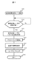
入側帯域制御部404に到着したパケットは、パケット処理部500のパケット判定回路502で内部ヘッダ部1000のRDビット1003に1が設定されているか判定される。RDビット1003に1が設定されている場合はRD要求パケットと判定されパケットバッファ部505のユーザ毎のキューに一時的に蓄積される(図12の1201と1202)。RDビット1003に1が設定されていない場合は入側帯域制御部404での帯域制御が不要なため一時保管バッファ部503に一時的に蓄積される。パケットバッファ部505は、RD要求パケットを受信すると、パケット受信情報514としてユーザ識別番号をパケット送出予定時刻計算回路510及び二分木ソート回路511に向けて通知する。
(Process 1) Received Packet Determination Processing A packet that has arrived at the ingress
(処理2)送信予定時刻計算(パケット受信時)
パケット受信情報514を受けたパケット送出予定時刻計算回路510は、ユーザソーティング情報メモリ513から、二分木ソート回路511経由でユーザ(p)のユーザソーティング情報の送信予定時刻とVLD情報を読み出す。また、VLDが‘0’であるか‘1’であるかを調べる(図12の1203)。VLDが‘1’であるときは、すでに該ユーザに送信待ちRD要求パケットが存在していることを示している。この場合、送信予定時刻を更新すると設定帯域を守ることが出来なくなるので、送信予定時刻を変更すべきでない。そこで、先ほどユーザソーティング情報メモリ513から読み出した送信予定時刻とRD要求パケット蓄積有無情報“有り”(VLD=1)の情報を、二分木ソート回路511に向けて、送信する(図12の1204)。
(Process 2) Scheduled transmission time calculation (during packet reception)
Upon receiving the
一方、VLDが‘0’であるときは、既に計算してある送信予定時刻が現在時刻を基準としたときに末来である(図12の1205)にもかかわらず送信予定時刻を更新すると、設定帯域を守ることが出来なくなるので、送信予定時刻を更新すべきではない。そこで、ユーザソーティング情報メモリ513から読み出した送信予定時刻とRD要求パケット蓄積有無情報“有り”(VLD=1)の情報を、二分木ソート回路511に向けて、送信する(図12の1204)。VLDが‘0’で、既に計算してある送信予定時刻が現在時刻を基準として過去または現在時刻と同時刻である場合(図12の1205)には、RD要求パケットはいつでも送信してよい状態となっているので送信予定時刻を適当な時刻に更新しても良い。この場合には、受信RD要求パケットの属するフローのパケットを最も早く送信させるために、
新規送信予定時刻=現在時刻+1
と、RD要求パケット蓄積情報を‘有り’と判定し、二分木ソート回路511に向けて、判定したこれらの情報を送信する(図12の1206)。
On the other hand, when VLD is “0”, updating the scheduled transmission time despite the fact that the estimated transmission time already calculated is based on the current time (1205 in FIG. 12), Since the set bandwidth cannot be protected, the scheduled transmission time should not be updated. Therefore, the information of the scheduled transmission time read from the user sorting information memory 513 and the RD request packet accumulation presence / absence information “present” (VLD = 1) is transmitted to the binary tree sort circuit 511 (1204 in FIG. 12). When VLD is “0” and the already calculated estimated transmission time is the same as the past or the current time based on the current time (1205 in FIG. 12), the RD request packet may be transmitted at any time. Therefore, the scheduled transmission time may be updated to an appropriate time. In this case, in order to send the packet of the flow to which the received RD request packet belongs the earliest,
New transmission scheduled time =
Then, the RD request packet accumulation information is determined to be “present”, and the determined information is transmitted to the binary tree sort circuit 511 (1206 in FIG. 12).
(処理3)ソーティング処理(パケット受信時)
パケットを受信し、ユーザの送信予定時刻が更新されると、ユーザの中で最も早くパケットを送信すべきユーザ(以下、暫定送信ユーザ)が変化している可能性がある。二分木ソート回路511において暫定送信ユーザを再判定するためのソーティングを行う(図12の1207)。
(Process 3) Sorting process (when receiving a packet)
When a packet is received and the scheduled transmission time of the user is updated, there is a possibility that the user (hereinafter, provisional transmission user) who should transmit the packet earliest among the users has changed. The binary tree sort circuit 511 performs sorting for re-determining the provisional transmission user (1207 in FIG. 12).
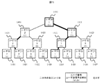
以下に8ユーザ(ユーザ(p):pは0から7の整数)存在し、これらの中から暫定送信ユーザとして一ユーザを選ぶ場合を、図14、図15を用いて説明する。図14はソーティング処理を行うための二分木構造を示している。二分木の頂点(以下、“根”と呼ぶ)、分岐点、先端(以下、“葉”と呼ぶ)にはエントリがある。二分木の根に位置するエントリを根エントリ、葉に位置するエントリを葉エントリ、任意のエントリからみて根側にあるエントリを親エントリ、葉側にある二つのエントリを子エントリと呼ぶ。
ユーザ情報エリアの葉エントリ1430〜1437(ユーザ番号順に並べておく)にはユーザ識別番号、各ユーザの送信予定時刻とVLD(括弧内の数値(0または1)がVLDを示す)が記憶してある。葉エントリを除く他のエントリにも同様の情報が記憶される。親エントリには配下の子エントリの一方が選択され格納される。この選択は以下の[1]〜[3]の規則に従う。
In the following, there are 8 users (user (p): p is an integer from 0 to 7), and the case where one user is selected as a provisional transmission user from among these will be described with reference to FIGS. FIG. 14 shows a binary tree structure for performing the sorting process. There are entries at the apex (hereinafter referred to as “root”), branch point, and tip (hereinafter referred to as “leaf”) of the binary tree. An entry located at the root of the binary tree is called a root entry, an entry located at a leaf is called a leaf entry, an entry on the root side from an arbitrary entry is called a parent entry, and two entries on the leaf side are called child entries.
The user information
[1] 子エントリのVLDが共に‘1’のときは、送信予定時刻がより過去である子エントリを親エントリとして選択する。例えばエントリ1420には、エントリ1431の情報がそのまま記憶される。送信予定時刻が同じ場合はどちらでも良い。
[2] 一方の子エントリのVLDが‘1’、他方が‘0’のときは、VLDが‘1’である子エントリを親エントリとして選択する。例えばエントリ1422には、VLDが‘1’のエントリ1435の情報が記憶される。
[3] 子エントリのVLDが共に‘0’のときは、送信予定時刻がより過去である子エントリを親エントリとして選択する。例えば、エントリ1421には、エントリ1432の情報がそのまま記憶される。送信予定時刻が同じ場合はどちらでも良い。
[1] When both the VLDs of the child entries are “1”, the child entry whose transmission scheduled time is earlier is selected as the parent entry. For example, the
[2] When the VLD of one child entry is “1” and the other is “0”, the child entry whose VLD is “1” is selected as the parent entry. For example, the
[3] When both of the VLDs of the child entries are “0”, the child entry whose transmission scheduled time is earlier is selected as the parent entry. For example, the
次に、ユーザソーティング情報メモリ513のユーザソーティング情報の管理方法について説明する。ここではユーザ数をM(=2のm乗)とする。例として、8フロー(m = 3)を収容するユーザソーティング情報メモリ513のメモリマップを図11に示す。前述の様に、ユーザソーティング情報メモリ513には、ユーザ毎にユーザ識別番号1100、送信予定時刻1101、およびVLD1102が記憶されている。各エントリと、ユーザソーティング情報メモリ513のアドレスの関係は、以下に示す通りである。以下では、アドレスは2進数(m+1ビット)で示すこととする。
Next, a method for managing user sorting information in the user sorting information memory 513 will be described. Here, the number of users is M (= 2 to the power of m). As an example, FIG. 11 shows a memory map of the user sorting information memory 513 that accommodates 8 flows (m = 3). As described above, the user sorting information memory 513 stores the
(1) 二分木の根に対応するアドレスは、000…001番地である。
(2) アドレス:xyy…yyz番地のエントリの親エントリのアドレスは0xy…yyy番地であり、二つの子エントリのアドレスはyyy…yz0番地とyyy…yz1番地である。葉エントリに対応するアドレスは、100…000番地から111…111番地(全部で2のm乗=M個)に記憶される。以上の規則でメモリのアドレスを管理していると、ソーティング時に行うメモリアクセスのためのアドレス生成回路を簡単に構成することができる。即ち、xyy…yyz番地の比較相手はxyy…yy(z)番地に記憶してある情報((z)はzの’0’←→’1’反転を示す)であり、その比較結果を書き込むのは0xy…yyy番地である。
(1) The address corresponding to the root of the binary tree is 000... 001.
(2) Address: The address of the parent entry of the entry at address xyy ... yyz is address 0xy ... yyy, and the addresses of the two child entries are address yyy ... yz0 and address yyy ... yz1. Addresses corresponding to leaf entries are stored at
以下では入側帯域制御部404の具体的なフローソーティング処理動作を説明する。
まず、二分木ソート回路511はユーザソーティング情報メモリ513のユーザ(p)に対応する葉エントリのVLDをRD要求パケット蓄積有無情報に従った値 (RD要求パケット受信時にはパケット蓄積有無情報は常に”有”であるため常に’1’である) に、また、送信予定時刻をパケット送出予定時刻計算回路510が通知する送信予定時刻に更新する。例えば図14において、ユーザ(4)の送信予定時刻が更新される場合、葉エントリ1434を書き換える。次に、葉エントリ以外の更新を行うが、二分木のすべてのエントリが更新される訳ではない。例えば、前述の例の場合に更新されるのは、葉エントリ1434から根エントリ1400に向かう経路にあるエントリ1422、1411、1400のみである。二分木ソート回路511はこれらのエントリを読みだして前述の[1]〜[3]の規則に従ってユーザ識別番号、送信予定時刻、VLDを更新する。(図12の1208と1209)更新結果を図15に示す。更新の結果ユーザ(4)が根エントリに選択された(図15の1500〜1534)。本処理が終了するとパケット受信時の処理は終了する。
以下、パケット送信時の処理4〜6を説明する。
Hereinafter, a specific flow sorting process operation of the ingress side
First, the binary tree sort circuit 511 sets the value of the VLD of the leaf entry corresponding to the user (p) in the user sorting information memory 513 according to the RD request packet storage presence / absence information. The transmission scheduled time is updated to the scheduled transmission time notified by the packet transmission scheduled
Hereinafter, processes 4 to 6 at the time of packet transmission will be described.
(処理4)送信ユーザ選択処理
二分木ソート回路511によって選ばれた暫定送信ユーザをユーザ(i)とする。また、以下では、現在時刻と送信予定時刻を比較した結果、現在時刻を基準として送信予定時刻が過去または同時刻であるとき、該ユーザは送信可能状態であると呼ぶことにする。送信制御部512は、パケットバッファ部505から送信起動信号517を受信するとユーザソーティング情報メモリ513の根エントリ内のVLDと送信予定時刻を読み出し、ユーザ(i)が送信可能状態か否かを監視する。ユーザが送信可能状態となっていない場合には、パケット受信による送信予定時刻の変更または、時間経過によりユーザが送信可能状態となるまで待機する(図13の1300〜1302)。送信可能状態となっている場合には、送信許可信号516をパケットバッファ部505へ出す。
(Processing 4) Transmission user selection process The provisional transmission user selected by the binary tree sort circuit 511 is defined as a user (i). In the following, when the current time and the scheduled transmission time are compared, and the scheduled transmission time is in the past or the same time with the current time as a reference, the user is referred to as being in a transmittable state. When receiving the
送信許可信号516を受信したパケットバッファ部505は、送信要求のあったユーザのキューからRD要求パケットを読み出す準備をし、送信判定回路508へ判定要求信号を出す。送信判定回路は一時保管バッファ部503とパケットバッファ部505のどちらからパケットを読み出すかを決定し、送信決定信号を一時保管バッファ部503とパケットバッファ部505のどちらかへ出す。送信判定回路から送信決定信号を受信したパケットバッファ部505はRD要求パケットを送信する(図13の1303)。さらに、RD要求パケットを送信したユーザのユーザ識別番号、送信したRD要求パケットの要求データ長1006、該ユーザの(パケット送信後の)パケット蓄積有無から構成されるRD要求パケット送信情報515をパケット送出予定時刻計算回路510と二分木ソート回路511へ送信する。また、パケットバッファ部505は次回送出するRD要求パケットを問い合わせるために、送信許可信号516を送信制御部512へ送信する。
Upon receiving the
(処理5)送信予定時刻計算(パケット送信時)
パケット送信情報515を受信したパケット送出予定時刻算出回路510は、設定するユーザの契約帯域に従ったユーザの送信予定時刻を計算する(図13の1304)。新規の送信予定時刻の計算は、例えば、1Byteのデータを送信する際の時間間隔を記憶しておき、以下の計算を行えばよい。
新規送信予定時刻=今回の送信予定時刻+時間間隔×要求データ長のバイト数
あるいは各ユーザの帯域が、The ATM Forum Specification version 4.0の4.4.2章に記載されているContinuous−State Leaky Bucket Algorithmの遵守・違反判定において、遵守と判定されるように新規送信予定時刻を計算しても良い。
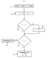
リーキーバケットアルゴリズムはある容量を持った穴の空いた漏れバケツのモデルで表され、バケツに水が入っている間は監視帯域に比例した量の水が漏れ、RD要求パケット到着時にはバケツに要求データ長分の水が注ぎ込まれる。ストレージ装置およびユーザ100から創出されるRDデータのバーストを許容するためにバケツに容量を持ち、バケツが溢れないうちは契約帯域を遵守と、溢れると違反と判定する。リーキーバケットアルゴリズムのフローチャートを図19に示す。
(Process 5) Scheduled transmission time calculation (during packet transmission)
Upon receiving the packet transmission information 515, the packet transmission scheduled
New transmission scheduled time = current transmission scheduled time + time interval x number of bytes of requested data length or the bandwidth of each user is determined by the Continuous-State Leaky Bucket Algorithm described in Chapter 4.4.2 of The ATM Forum Specification version 4.0 In the compliance / violation determination, a new transmission scheduled time may be calculated so as to determine compliance.
The leaky bucket algorithm is expressed as a leaky bucket model with a certain capacity, and when the bucket is filled with water, the amount of water leaks in proportion to the monitoring bandwidth, and when the RD request packet arrives, the request data is stored in the bucket. A long amount of water is poured. The bucket has a capacity to allow a burst of RD data created from the storage device and the
RD要求パケットが時間taに到着すると(ステップ1901)、前回遵守と判定されたRD要求パケットの到着時刻:LCTとの差分(バケツから漏れる水量に対応)が計算される。この値をカウンタ値:X(バケツの蓄積量に対応)から減算したX’が計算され (ステップ1902)、X’が負の場合にはX’が”0”に修正される(ステップ1903 ステップ1904)。X’とリミット:L(バケツの容量に対応)との比較が行われ (ステップ1905)、X’≧Lの場合にストレージ装置105から送出されるRDデータは違反と判定される(ステップ1906)。X’<Lの場合に遵守と判定され、X’に監視帯域より決まる固定値:I(要求データ長分の水量に対応)を加えた値がXとして保存される(ステップ1907)。なお、最初のRD要求パケットが到着した時に、X=0、LCTは該RD要求パケットの到着時刻に初期化される。
以上に説明した計算方法により計算された送信予定時刻と、パケット送信情報515内のパケット蓄積有無を、そのまま二分木ソート回路511に送信する。
When the RD request packet arrives at time ta (step 1901), the difference between the arrival time of the RD request packet determined to comply with the previous time: LCT (corresponding to the amount of water leaking from the bucket) is calculated. X 'is calculated by subtracting this value from the counter value: X (corresponding to the amount of accumulated bucket) (step 1902). If X' is negative, X 'is corrected to "0" (step 1903 step) 1904). A comparison is made between X ′ and limit: L (corresponding to the capacity of the bucket) (step 1905). If X ′ ≧ L, the RD data sent from the
The scheduled transmission time calculated by the calculation method described above and the packet storage presence / absence in the packet transmission information 515 are transmitted to the binary tree sort circuit 511 as they are.
(処理6)
RD要求パケットを送信して送信予定時刻を修正した場合には、RD要求パケットを受信した場合と同一の処理を行う(図13の1305と1306)。処理6は処理3に対応する。
次に、本発明の出側帯域制御部408の動作について説明する。出側帯域制御部408は入側帯域制御部404と同じ構成を取る。
異なる点は、入側帯域制御部404ではRD要求パケットに対し送信制御を行い、RDデータパケットによるトラヒック量がユーザの広域ネットワーク網の契約帯域を違反しないように制御するのに対し、出側帯域制御部408では、R2Tパケットに対し送信制御を行い、WRデータパケットによるトラヒック量がユーザの広域ネットワーク網の契約帯域を違反しないように制御する点である。
具体的にはパケット判定回路502で、内部パケット1000のR2Tビット1004に1が設定されているかどうかでR2Tパケットを識別し、R2Tパケットはパケットバッファ部505へ格納する。
(Process 6)
When the scheduled transmission time is corrected by transmitting the RD request packet, the same processing as when the RD request packet is received is performed (1305 and 1306 in FIG. 13).
Next, the operation of the outgoing side
The difference is that the ingress
Specifically, the packet determination circuit 502 identifies the R2T packet based on whether or not 1 is set in the
また、入側帯域制御部404では、パケットバッファ部505からRD要求パケットが送出された後に、送出したRD要求パケットの要求データ長1006とユーザ識別番号と該ユーザの(パケット送信後の)パケット蓄積有無から構成されるRD要求パケット送信情報515をパケット送出予定時刻計算回路510と二分木ソート回路511へ送信している。出側帯域制御部408では、パケットバッファ部505からR2Tパケットが送出された後に、送出したR2Tパケットの要求データ長1006とユーザ識別番号と該ユーザの(パケット送信後の)パケット蓄積有無から構成されるR2Tパケット送信情報をパケット送出予定時刻計算回路と二分木ソート回路へ送信する。それを除く他の動作に関しては入側帯域制御部404と出側帯域制御部408は同じ動作をする。
In addition, after the RD request packet is transmitted from the
上述する二分木ソート回路を使用することにより、次回パケットを送出することの出来るパケットバッファ部505のキューを高速に選択することが可能となる。
なお、パケット判定回路502、送信判定回路508、パケット送出予定時刻計算回路510、二分木ソート回路511、送信制御部512は、それぞれ演算装置と記憶装置を含む機能モジュールで実現され、一時管理バッファ503、パケットバッファ部505、ユーザソーティング情報メモリ513はそれぞれ記憶装置で実現される。ただし、図5の装置構成と同等の機能で本発明の目的が達成されれば、これ以外の装置構成であってもよい。
By using the binary tree sort circuit described above, it is possible to select at high speed a queue of the
Note that the packet determination circuit 502, the
本発明のiSCSIに適した帯域制御機能を有するストレージスイッチを使用することにより、RDデータパケット、WRデータパケットをパケットバッファ部に蓄積することなく帯域制御を行うことができるため、帯域制御部でのバッファ量を大幅に削減可能となる。また、広域ネットワーク網102でのユーザの契約帯域を違反することのないタイミングでRD要求パケット、R2Tパケットを転送するため、ストレージ装置およびユーザのコンピュータ端末装置が過剰にデータを送出することがなくなるため、リソースの有効利用に繋がる。さらに、従来の帯域制御装置ではRDデータパケットとWRデータパケットの帯域制御を行うためには、ユーザ側から広域ネットワークへの入り口とストレージ側から広域ネットワークの入り口への二つの装置が必要であったが、本発明の装置では一つの装置でRDデータパケットとWRデータパケットの両方の帯域制御を行うことが可能となる。
また、本発明の帯域制御機能を有するストレージスイッチ104とストレージ装置108とを1個の装置とすることで、ディスクアレイ制御装置と見立てることが可能である。
By using a storage switch having a bandwidth control function suitable for iSCSI of the present invention, bandwidth control can be performed without accumulating RD data packets and WR data packets in the packet buffer unit. The amount of buffer can be greatly reduced. In addition, since the RD request packet and the R2T packet are transferred at a timing that does not violate the user's contracted bandwidth in the
Further, the
本発明のiSCSIに適した帯域制御機能を有するストレージスイッチであり、RD要求パケットもしくはR2Tパケット(以下、RD要求パケットとR2Tパケットを総称してデータ要求パケットと呼ぶ)で要求する要求データ長が大きい場合に複数のデータ要求パケットに分割する機能を有する実施例を、図16を用いて説明する。本実施例を用いることで、一つのデータ要求パケットでイニシエータ、またはターゲットから送出されるデータ量の上限を設けることができる。
図16は本発明のストレージスイッチ104を表している。ストレージスイッチ104はパケットが入力するn個の入力回線1612−i(i=1〜n)と、パケットが出力されるn個の出力回線1613−i(i=1〜n)と、n個のスイッチインタフェース1600−i(i=1〜n)と、スイッチ部1601より構成される。
This is a storage switch having a bandwidth control function suitable for iSCSI of the present invention, and requires a long request data length with an RD request packet or R2T packet (hereinafter, the RD request packet and R2T packet are collectively referred to as a data request packet). An embodiment having a function of dividing the data request packet into a plurality of data request packets will be described with reference to FIG. By using this embodiment, it is possible to set an upper limit on the amount of data transmitted from the initiator or target in one data request packet.
FIG. 16 shows the
スイッチインタフェース1600−iは、パケットの受信処理を行うパケット受信回路1602と、ユーザ100の認証処理やiSCSIパケットなどの終端処理とストレージ装置105−iのストレージボリューム構成情報解決と要求データ長が大きい場合にデータ要求パケットを分割するパケット分割部1611を備えるiSCSI処理部1603と、一つのデータ要求パケットで要求可能なRDデータ量およびWRデータ量の上限をユーザ毎に管理する閾値レジスタ1605と、入側帯域制御部1604と、出側帯域制御部1608と、パケットの送信処理を行うパケット送信回路1610と、ストレージ装置105−iのストレージボリューム情報とユーザ100がアクセス可能なストレージ装置105−iのボリューム情報を管理するユーザ管理テーブル1606と、IPパケットのルーティング情報を管理するルーティング管理テーブル1607と、iSCSI処理部1603で分割したデータ要求パケットの分割前と分割後の構成情報を管理する分割管理テーブル1609から構成される。また、スイッチインタフェース1600−iにはIPアドレスが割り振られている。図16では、スイッチインタフェース毎の入出力回線数は1個であるが、複数個用意されていても問題ない。
The switch interface 1600-i has a
実施例2で示したストレージスイッチと本実施例のストレージスイッチはiSCSI処理部1603にパケット分割部1611を備えること、一つのデータ要求パケットで要求可能なデータ量の上限をユーザ単位で管理する閾値レジスタを備えること、iSCSI処理部1603で分割したデータ要求パケットの情報を管理する分割管理テーブル1609を備えること、ユーザ管理テーブル1604に分割管理ビットを備えることを除き同じである。
iSCSI処理部1603はパケット受信回路1602からデータ要求パケットを受信すると実施例2で説明したiSCSI処理部1603での処理を実行した後に閾値レジスタ1605で管理しているユーザ毎の最大要求データ長(つまり要求可能なデータ量の上限)を読み出し、要求データ長706と大きさの比較を行う。閾値レジスタ1605の値は管理コンソール107から設定が可能である。比較の結果要求データ長706が最大要求データ長よりも大きい場合はユーザ管理テーブル1606に分割管理ビットを立ててパケット分割が行われたことを示す。次にパケット分割部1611で分割処理が行われる。
The storage switch shown in the second embodiment and the storage switch of the present embodiment include a packet dividing unit 1611 in the iSCSI processing unit 1603, and a threshold register that manages the upper limit of the amount of data that can be requested by one data request packet for each user. Are the same except that the management unit 1603 includes a division management table 1609 for managing information of the data request packet divided by the iSCSI processing unit 1603 and the user management table 1604 includes a division management bit.
When the iSCSI processing unit 1603 receives the data request packet from the
パケット分割部1611は要求データ長が最大要求データ長を超えているデータ要求パケットを分割する。R2TパケットとRD要求パケットで処理が異なる。
要求パケットがR2Tパケットの場合の処理は以下の通りである。
自インタフェース宛てR2Tパケットを受信したiSCSI処理部1603は対応するユーザの最大要求データ長を閾値レジスタ1605から読み出し、要求データ長と比較を行う。要求データ長が最大要求データ長を超える場合、iSCSI処理部は従来技術1で説明したパケット情報と併せてパケット分割フラグを設定して、これらをユーザ管理テーブル1606で管理する。次にiSCSI処理部はパケット分割部へR2Tパケットとともに分割依頼を出す。パケット分割部は、オリジナルのR2Tパケットのコピーをn個作成(例えば、要求WR長が96キロバイトで、最大要求データ長が24キロバイトの場合はn=4となる。)する。次に要求WR長803を最大要求データ長に書き換え、一つ目のR2Tパケットの場合はR2TSN 802に0をセットする。分割したR2Tパケットのイニシエータタスクタグ、ターゲットタスクタグ、元のR2TパケットのR2TSN、分割個数、分割後のR2Tパケットへ割り振ったR2TSNなどの情報を分割管理テーブルへ書き込み、R2TパケットをiSCSI処理部へ渡す。
The packet division unit 1611 divides a data request packet whose request data length exceeds the maximum request data length. Processing is different for R2T packets and RD request packets.
Processing when the request packet is an R2T packet is as follows.
The iSCSI processing unit 1603 that has received the R2T packet addressed to its own interface reads the maximum request data length of the corresponding user from the
自インタフェース宛てWRデータパケットを受信した場合、iSCSI処理部1603はユーザ管理テーブル1606でユーザ識別番号の解決などを行った後に、分割管理ビットを確認する。分割管理ビットが設定されている場合はパケット分割部へ渡す。パケット分割部1611はイニシエータタスクタグ、ターゲットタスクタグ、ユーザ識別番号から分割管理テーブル1609を検索し、受信したWRデータパケットに対応する情報を分割管理テーブル1609から取得する。イニシエータはR2Tパケットに対する最後のWRデータパケットにはFビットを1に設定する。しかし、R2Tパケットを分割している場合はFビットに1が設定されているWRデータパケットであっても、分割前のR2Tパケットでは途中の可能性がある。そのため、受信したWRデータパケットが分割R2Tパケットに対応するならば、現在何バイトのWRデータパケットを受信したかを分割管理テーブルで管理しておく。 When the WR data packet addressed to its own interface is received, the iSCSI processing unit 1603 confirms the division management bit after resolving the user identification number in the user management table 1606. When the division management bit is set, it is passed to the packet division unit. The packet division unit 1611 searches the division management table 1609 from the initiator task tag, the target task tag, and the user identification number, and acquires information corresponding to the received WR data packet from the division management table 1609. The initiator sets the F bit to 1 in the last WR data packet for the R2T packet. However, if the R2T packet is divided, even if it is a WR data packet in which the F bit is set to 1, there is a possibility that the R2T packet before the division is in the middle. Therefore, if the received WR data packet corresponds to the divided R2T packet, the division management table manages how many bytes of the WR data packet are currently received.
分割前のR2Tでは途中パケットに当てはまる場合はFビットに1が設定されていても、Fビットを0に変更する。また、WRデータパケットのDataSN 901はR2Tパケット単位で、リセットされるのだが、分割されたR2Tパケットに対するWRデータパケットの場合は連続した値に変更する。その後入側帯域制御部1604へパケットは転送される。これらの処理をするための情報は分割管理テーブルで管理されている。元のR2Tパケットに対応するWRデータパケットを全て送信し終わった場合、分割管理テーブルからエントリを削除する。また同時に、分割管理テーブルはエントリ削除信号1614で先程分割管理テーブルから削除したエントリをユーザ管理テーブルから削除するように指示を出す。エントリ削除信号1614を受信したユーザ管理テーブル1606は該当するエントリを削除する。
上記方式を用いてR2Tパケットを分割することで、最大要求データ長を超えるR2Tパケットをユーザ100に転送することで、ユーザ100から大量のデータがバースト的にネットワークに発生することを防止できる。
In the case of R2T before division, if it is applicable to a packet in the middle, the F bit is changed to 0 even if 1 is set in the F bit. Further,
By dividing the R2T packet using the above method, the R2T packet exceeding the maximum required data length is transferred to the
また、上記方式を用いてR2Tパケット管理することで、ユーザ100及びストレージ装置105は、スイッチがR2Tパケットを分割して転送していることを意識しなくて良い。
要求パケットがRD要求パケットの場合の処理は以下の通りである。
RD要求パケットはSCSIのCDB(Command Descriptor Block)をヘッダ部に保有している。RD要求パケットのSCSI CDBはRDデータのストレージ上のブロックアドレスと転送するデータのブロック数情報を保持している。そのため、パケット分割を行う場合はSCSI CDBのブロックアドレスの値と転送ブロック数を変更する必要がある。ブロックアドレス数と転送ブロック数を変更するためにはストレージスイッチはストレージ装置105−iで使用している1ブロックのサイズ(以下ブロックサイズ)を知っておく必要がある。そのため、分割管理テーブル1609はストレージ装置105−iの1ブロックサイズを管理している。1ブロックサイズはiSCSIのログイン時の情報と一緒に取得できる。また、管理コンソール107より設定することも可能である。
In addition, by managing R2T packets using the above method, the
Processing when the request packet is an RD request packet is as follows.
The RD request packet has SCSI CDB (Command Descriptor Block) in the header. The SCSI CDB of the RD request packet holds the block address on the RD data storage and the number of blocks of data to be transferred. Therefore, when packet division is performed, it is necessary to change the value of the SCSI CDB block address and the number of transfer blocks. In order to change the number of block addresses and the number of transfer blocks, the storage switch needs to know the size of one block (hereinafter referred to as the block size) used in the storage apparatus 105-i. Therefore, the division management table 1609 manages one block size of the storage apparatus 105-i. One block size can be obtained together with information at the time of iSCSI login. It can also be set from the
自インタフェース宛てRD要求パケットをイニシエータから受信したiSCSI処理部1603は対応するユーザの最大要求データ長を閾値レジスタ1605から読み出し、要求データ長と比較を行う。要求データ長が最大要求データ長を超える場合、iSCSI処理部は従来技術1で説明したパケット情報と併せてパケット分割フラグを設定して、これらをユーザ管理テーブルで管理する。次にiSCSI処理部はパケット分割部へRD要求パケットとともに分割依頼を出す。パケット分割部は、オリジナルのRD要求パケットのコピーをn個作成(例えば、要求データ長が96キロバイトで、最大要求データ長が24キロバイトの場合はn=4となる。)する。次に要求データ長を最大要求データ長に書き換え、SCSI CDBの転送ブロック数およびブロックアドレスを書き直す。転送ブロック数は最大要求データ長と同じとなるブロック数を1ブロックサイズと最大要求データ長から割り出し書き込む。また、ブロックアドレスは分割後の第一番目のRD要求パケットのSCSI CDBにはオリジナルのRD要求パケットのSCSI CDBのブロックアドレスの値を書き込む。第二番目以降には前回送出データに続くブロックアドレスを設定する。分割したRD要求パケットのイニシエータタスクタグ、ターゲットタスクタグ、元のRD要求パケットの分割個数、などの情報を分割管理テーブルへ書き込む。
The iSCSI processing unit 1603 that has received the RD request packet addressed to its own interface from the initiator reads the maximum requested data length of the corresponding user from the
自インタフェース宛てRDデータパケットをターゲットから受信した場合、iSCSI処理部1603はユーザ管理テーブル1606でユーザ識別番号の解決などを行った後に、分割管理ビットを確認する。分割管理ビットが設定されている場合はパケット分割部1611へ渡す。パケット分割部1611はイニシエータタスクタグ、ターゲットタスクタグ、ユーザ識別番号から受信したRDデータパケットが分割したRD要求パケットのどれに対応するかを分割管理テーブル1609で確認する。ターゲットはRD要求パケットに対する最後のRDデータパケットではFビットを1に設定する。しかし、RD要求パケットを分割している場合はFビットに1が設定されているRDデータパケットであっても、元のRD要求パケットでは途中のパケットの可能性がある。そのため、受信したRDデータパケットが分割RD要求パケットに対応するならば、現在何バイトのRDデータパケットを転送したかを分割管理テーブルで管理しておき、Fビットに1が設定されていた場合でも元のRD要求パケッでは途中に当る場合はFビットを0に変更する。 When the RD data packet addressed to the own interface is received from the target, the iSCSI processing unit 1603 confirms the division management bit after resolving the user identification number in the user management table 1606. When the division management bit is set, the packet is transferred to the packet division unit 1611. The packet division unit 1611 confirms in the division management table 1609 which of the divided RD request packets the RD data packet received from the initiator task tag, the target task tag, and the user identification number corresponds to. The target sets the F bit to 1 in the last RD data packet for the RD request packet. However, when the RD request packet is divided, even if the RD data packet has the F bit set to 1, the original RD request packet may be an intermediate packet. Therefore, if the received RD data packet corresponds to the divided RD request packet, the number of bytes of the RD data packet currently transferred is managed in the divided management table, and even when the F bit is set to 1. If the original RD request packet is halfway, the F bit is changed to 0.
また、RDデータパケットのDataSN 901はRD要求パケット単位で、リセットされるのだが、分割されたRD要求パケットに対するRDデータパケットの場合は連続した値に変更する。その後出側帯域制御部1608へパケットは転送される。これらの処理をするための情報は分割管理テーブルで管理されている。元のRD要求パケットに対応するRDデータパケットを全て送信し終わった場合、分割管理テーブルからエントリを削除する。また同時に、分割管理テーブルはエントリ削除信号1614で先程分割管理テーブルから削除したエントリをユーザ管理テーブルから削除するように指示を出す。エントリ削除信号1614を受信したユーザ管理テーブル1606は該当するエントリを削除する。
上記方式を用いてRD要求パケットを分割することで、最大要求データ長を超えるRD要求パケットをストレージ装置105に転送することで、ストレージ装置105から大量のデータがバースト的にネットワークに発生することを防止できる。
The
By dividing the RD request packet using the above method, transferring an RD request packet exceeding the maximum requested data length to the
また、上記方式を用いてRD要求パケット管理することで、ユーザ100及びストレージ装置105は、スイッチがRD要求パケットを分割して転送していることを意識しなくて良い。
なお、スイッチ部1601、パケット受信回路1602、iSCSI処理部1603、入側帯域制御部1604、出側帯域制御部1608、パケット送信回路1610は、それぞれ演算装置と記憶装置を含む機能モジュールで実現され、閾値レジスタ1605は記憶装置で実現され、ユーザ管理テーブル1606、ルーティング管理テーブル1607、分割管理テーブル1609はそれぞれ記憶装置で実現される。ただし、図16の装置構成と同等の機能で本発明の目的が達成されれば、これ以外の装置構成であってもよい。
In addition, by managing the RD request packet using the above method, the
Note that the switch unit 1601, the
iSCSIに適した帯域制御機能を有するストレージスイッチに実施例3で示すデータ要求コマンドを分割する機能を追加することで実施例2よりの小さい単位で帯域制御を行うことが可能となる、そのため、実施例2よりもさらにデータのバースト性を小さく抑えることの出来る帯域制御を提供可能とする。 By adding a function for dividing the data request command shown in the third embodiment to a storage switch having a bandwidth control function suitable for iSCSI, it becomes possible to perform bandwidth control in a smaller unit than in the second embodiment. As compared with Example 2, it is possible to provide bandwidth control capable of suppressing the burst property of data.
実施例2および実施例3では、データセンタ103内にあるストレージスイッチ104と、データセンタ103と広域ネットワーク網102とを接続するパケット転送装置とが分離している実施例を示した。
実施例4ではパケット転送装置101−2とストレージスイッチ104とが融合し、かつIP、iSCSI、FCプロトコルを1筐体でサポートする実施形態について説明する。
マルチプロトコル対応ストレージスイッチ1700は図17に示す、データセンタと広域ネットワークの間に位置し、パケット転送装置101−2とストレージスイッチ104の両役割を持つ。
In the second and third embodiments, the
In the fourth embodiment, an embodiment will be described in which the packet transfer apparatus 101-2 and the
The multi-protocol
マルチプロトコル対応ストレージスイッチ1700はデータセンタ103内などに設置され、RAID装置やJBOD(Just Bunch Of Disks)などのストレージ装置105−iと、IPネットワークもしくはFCネットワークで接続しSAN106を形成する。マルチプロトコル対応ストレージスイッチ1700とストレージ装置105−iは複数のスイッチを経由して接続する形態を取ることもある。
マルチプロトコル対応ストレージスイッチ1700の詳細を図20に示す。マルチプロトコル対応ストレージスイッチ1700はiSCSIインタフェース2000と、ネットワークIPインタフェース2001と、IP/FC変換インタフェース2001と、ストレージネットワークIPインタフェース2003とスイッチ部403からなる。上記4種類のインタフェースはマルチプロトコル対応ストレージ1700に接続するネットワークに応じて最適なインタフェースが選択される。
The multi-protocol
Details of the multi-protocol
iSCSIインタフェース2000は、ストレージ装置にアクセスするユーザが接続するネットワークを接続するために用いる。iSCSIインタフェース2000の主な構成要素は、iSCSI処理部403、入り側帯域制御部404、出側帯域制御部408、帯域監視部2004からなる。iSCSI処理部403、入り側帯域制御部404、出側帯域制御部408は、ストレージスイッチ104のものと同じである。帯域監視部2004は、マルチプロトコル対応ストレージスイッチ1700から広域ネットワークへ転送するデータ量がユーザ契約帯域を越えるかどうかを監視する。ネットワークへ転送するデータ量がユーザ契約帯域を越えた場合、帯域監視部2004は、ユーザ帯域を越えたデータの廃棄処理や、優先順位を低く設定してネットワークへ転送するなどを行う。
The iSCSI interface 2000 is used to connect a network to which a user accessing the storage apparatus is connected. The main components of the iSCSI interface 2000 include an
ネットワークIPインタフェース2001は、ストレージ装置にアクセスしないユーザが接続するネットワークを接続するために用いる。ネットワークIPインタフェース2001の主な構成要素は、帯域監視部2004とIPルーティング部2005である。IPルーティング部2005はIPパケットの宛先アドレス検索などのルーティング処理をする。
IP/FC変換インタフェース2002はFCプロトコル対応のストレージ装置もしくはFCプロトコル対応のコンピュータを接続するインタフェースである。IP/FC変換インタフェース2002の主な構成要素は、IP/FC変換回路2006とFC送受信回路2007である。IP/FC変換回路2006は入力したFCプロトコルとIPとを変換する機能を有することを特徴とする。FC送受信回路2007はFCデータの送受信の処理を行う。
ストレージネットワークIPインタフェース2003は、帯域契約や帯域制御を行わないネットワークおよびiSCSI対応ストレージ装置を接続する。ストレージネットワークIPインタフェース2003の主な構成要素は、IPルーティング部2005である。
The network IP interface 2001 is used to connect a network to which a user who does not access the storage apparatus is connected. The main components of the network IP interface 2001 are a
The IP / FC conversion interface 2002 is an interface for connecting an FC protocol compatible storage device or FC protocol compatible computer. The main components of the IP / FC conversion interface 2002 are an IP /
The storage network IP interface 2003 connects a network that does not perform bandwidth contract or bandwidth control and an iSCSI-compatible storage device. The main component of the storage network IP interface 2003 is an
なお、iSCSI処理部403、入側帯域制御部404、出側帯域制御部408、帯域監視部2004、IPルーティング部2005、IP/FC変換回路2006、FC送受信回路2007は、それぞれ演算装置と記憶装置によって実現される。ただし、図20の装置構成と同等の機能で本発明の目的を達成可能ならば、これ以外の装置構成であってもよい。
本実施例を用いることで、パケット転送装置101−2とストレージスイッチ104を一つの筐体で実現することが出来る。
Note that the
By using this embodiment, the packet transfer apparatus 101-2 and the
100−i(i=1〜n):ユーザ、101−1,2:パケット転送装置、102:広域ネットワーク網、103:データセンタ、104:ストレージスイッチ、105−i(i=1〜n):ストレージ装置、106:SAN、107:管理コンソール。 100-i (i = 1 to n): user, 101-1, 2: packet transfer device, 102: wide area network, 103: data center, 104: storage switch, 105-i (i = 1 to n): Storage device, 106: SAN, 107: Management console.
Claims (9)
上記第一の装置から送信されたパケットを受信し、上記第二の装置へパケットを送信するパケト入出力部と、
上記受信したパケット内の情報から、上記第二の装置が上記パケットを受信した場合に、
上記第二の装置から上記第一の装置へ送信されるデータの量を解析するパケット解析部と、
上記パケットを保持する記憶装置と、
上記パケットを記憶装置に書き込むパケット処理部と、
上記解析されたデータの量と上記パケットを送信したユーザの保証帯域に応じて、上記保持されたパケットの上記第二の装置への送信を制御する転送制御部とを備え
上記パケット処理部は入力されたパケットが上記第二の装置にデータの送信を要求するパケットかどうかを判定し、
上記パケット解析部では、該パケット処理部で上記第二の装置にデータの転送を要求す
るパケットと判定されたパケットに対してのみ上記解析を行うことを特徴とするパケット
転送装置。 A packet transfer device connected to the first and second devices via a network,
A packet input / output unit for receiving a packet transmitted from the first device and transmitting the packet to the second device;
From the information in the received packet, when the second device receives the packet,
A packet analyzer for analyzing the amount of data transmitted from the second device to the first device;
A storage device for holding the packet;
A packet processing unit for writing the packet to a storage device;
A transfer control unit that controls transmission of the held packet to the second device in accordance with an amount of the analyzed data and a guaranteed bandwidth of a user who has transmitted the packet; Whether the received packet is a packet requesting data transmission to the second device,
The packet analysis unit, wherein the packet analysis unit performs the analysis only on a packet that is determined by the packet processing unit as a packet that requests the second device to transfer data.
フィック量が予め定められた帯域以上にならないように制御することを特徴とする請求項
1記載のパケット転送装置。 2. The packet transfer according to claim 1, wherein the transfer control unit controls the amount of traffic based on data transmitted from the second device to the first device so as not to exceed a predetermined bandwidth. apparatus.
徴とする請求項1記載のパケット転送装置。 The packet transfer apparatus according to claim 1, wherein the transfer control unit controls a time at which the packet is output to the second apparatus.
ケットを入力し、
上記転送制御部は、上記複数のパケットから一のパケットを選択し、上記選択された一
のパケットを優先して送信することを特徴とする請求項1記載のパケット転送装置。 The input / output unit inputs a plurality of packets respectively transmitted from a plurality of devices including the first device,
2. The packet transfer apparatus according to claim 1, wherein the transfer control unit selects one packet from the plurality of packets and preferentially transmits the selected one packet.
分割部を有することを特徴とする請求項1記載のパケット転送装置。 2. The packet transfer apparatus according to claim 1, wherein the packet processing unit includes a packet dividing unit that divides the held packet into a plurality of pieces and transmits the divided packets.
二の装置から上記第一の装置に送信されるデータの量が、上記分割される前のパケットを
受信した場合に上記第二の装置から上記第一の装置に送信されるデータの量よりも少なく
なるように分割されていることを特徴とする請求項5記載のパケット転送装置。 When each of the plurality of divided packets receives the packet before the division, the amount of data transmitted from the second device that received the divided packets to the first device 6. The packet transfer apparatus according to claim 5 , wherein the packet transfer apparatus is divided so as to be smaller than an amount of data transmitted from the second apparatus to the first apparatus.
二の装置から上記第一の装置に送信されるデータの量が、予め設定された上限値を超えな
いように分割されていることを特徴とする請求項6記載のパケット転送装置。 In each of the plurality of divided packets, the amount of data transmitted from the second device that has received the divided packets to the first device does not exceed a preset upper limit value. The packet transfer apparatus according to claim 6 , wherein the packet transfer apparatus is divided.
信されたパケットを、該第二のネットワーク上の送信先の装置へ転送可能なパケット転送
装置であって、
第一インタフェースと、
第二乃至第四のインタフェースのうち少なくともいずれか一のインタフェースと、上記
インタフェースのそれぞれと接続されたスイッチ部とを備え、
上記第一のインタフェースは、
上記第一のネットワークに接続されたインタフェースであって、
上記送信元の装置から上記送信先の装置へ送信された第一のプロトコルのパケットを送受信する入出力部と、
上記第一のプロトコルのパケットの転送処理を行う転送処理部と、
上記受信したパケット内の情報から、上記送信先の装置が上記パケットを受信した場合
に、上記送信先の装置から該パケットの送信元の装置へ送信されるデータ量を解析するパ
ケット解析部と、
上記受信した第一のプロトコルのパケットを保持する記憶部と、
上記解析されたデータの量と上記パケットを送信したユーザの保証帯域に応じて、上記
保持されたパケットの上記送信先への送信を制御する転送制御部を有し、
上記第二のインタフェースは、
上記第一のネットワークに接続されたインタフェースであって、
上記送信元の装置から上記送信先の装置へ送信された第二のプロトコルのパケットを送
受信する入出力部と、
上記第二のプロトコルのパケットの転送処理を行う転送処理部とを有し、
上記第三のインタフェースは、
上記第二のネットワークに接続されたインタフェースであって、
上記送信元の装置から上記送信先の装置へ送信された第一又は第二のプロトコルのパケ
ットを送受信する入出力部と、
上記第一又は第二のプロトコルのパケットを第三のプロトコルのパケットに変換する変換部と、
上記第三のプロトコルに変換されたパケットの転送処理を行う転送処理部とを有し、
上記第四のインタフェースは、
上記第二のネットワークに接続されたインタフェースであって、
上記送信元の装置から上記送信先の装置へ送信された第一又は第二のプロトコルのパケッ
トを送受信する入出力部と、
上記第一又は第二のプロトコルのパケットの転送処理を行う転送処理部とを有し、
上記スイッチ部は、
上記インタフェース間で転送されるパケットの入出力先を制御することを特徴とするパケット転送装置。 A packet transfer device connected to the first and second networks and capable of transferring a packet transmitted from a transmission source device on the first network to a transmission destination device on the second network. ,
A first interface;
At least one of the second to fourth interfaces, and a switch unit connected to each of the interfaces,
The first interface is
An interface connected to the first network,
An input / output unit for transmitting and receiving a packet of the first protocol transmitted from the transmission source device to the transmission destination device;
A transfer processing unit for transferring the packet of the first protocol;
A packet analysis unit for analyzing the amount of data transmitted from the transmission destination device to the transmission source device when the transmission destination device receives the packet from the information in the received packet;
A storage unit for holding the received packet of the first protocol;
A transfer control unit that controls transmission of the held packet to the destination according to the amount of the analyzed data and the guaranteed bandwidth of the user who transmitted the packet;
The second interface is
An interface connected to the first network,
An input / output unit that transmits and receives a packet of a second protocol transmitted from the transmission source device to the transmission destination device;
A transfer processing unit that performs transfer processing of the packet of the second protocol,
The third interface is
An interface connected to the second network,
An input / output unit for transmitting and receiving a packet of the first or second protocol transmitted from the transmission source device to the transmission destination device;
A conversion unit that converts the packet of the first or second protocol into a packet of the third protocol;
A transfer processing unit that performs transfer processing of the packet converted into the third protocol,
The fourth interface is
An interface connected to the second network,
An input / output unit for transmitting and receiving a packet of the first or second protocol transmitted from the transmission source device to the transmission destination device;
A transfer processing unit that performs transfer processing of the packet of the first or second protocol,
The switch part
A packet transfer apparatus for controlling an input / output destination of a packet transferred between the interfaces.
三のプロトコルはファイバチャネルであることを特徴とする請求項8のパケット転送装置
。 9. The packet transfer apparatus according to claim 8 , wherein the first protocol is iSCSI, the second protocol is TCP / IP, and the third protocol is Fiber Channel.
Priority Applications (2)
| Application Number | Priority Date | Filing Date | Title |
|---|---|---|---|
| JP2004008619A JP4214919B2 (en) | 2004-01-16 | 2004-01-16 | Storage switch with bandwidth control function |
| US10/889,139 US7133363B2 (en) | 2004-01-16 | 2004-07-13 | Storage switch with bandwidth control function |
Applications Claiming Priority (1)
| Application Number | Priority Date | Filing Date | Title |
|---|---|---|---|
| JP2004008619A JP4214919B2 (en) | 2004-01-16 | 2004-01-16 | Storage switch with bandwidth control function |
Publications (3)
| Publication Number | Publication Date |
|---|---|
| JP2005204092A JP2005204092A (en) | 2005-07-28 |
| JP2005204092A5 JP2005204092A5 (en) | 2006-12-21 |
| JP4214919B2 true JP4214919B2 (en) | 2009-01-28 |
Family
ID=34747186
Family Applications (1)
| Application Number | Title | Priority Date | Filing Date |
|---|---|---|---|
| JP2004008619A Expired - Fee Related JP4214919B2 (en) | 2004-01-16 | 2004-01-16 | Storage switch with bandwidth control function |
Country Status (2)
| Country | Link |
|---|---|
| US (1) | US7133363B2 (en) |
| JP (1) | JP4214919B2 (en) |
Families Citing this family (36)
| Publication number | Priority date | Publication date | Assignee | Title |
|---|---|---|---|---|
| JP2001111619A (en) * | 1999-10-12 | 2001-04-20 | Sony Corp | Transmitter, communication system and its communication method |
| BR0208493A (en) * | 2001-03-28 | 2005-12-13 | Qualcomm Inc | Power control for point-to-multipoint services provided in communication systems |
| US7853676B1 (en) * | 2004-06-10 | 2010-12-14 | Cisco Technology, Inc. | Protocol for efficient exchange of XML documents with a network device |
| JP4825580B2 (en) * | 2005-09-05 | 2011-11-30 | アラクサラネットワークス株式会社 | Method and apparatus for reducing power consumption of network connection device |
| US20070121633A1 (en) * | 2005-11-30 | 2007-05-31 | Michael Moretti | Active-active fibre channel capability in SATA and SAS devices |
| US20070121668A1 (en) * | 2005-11-30 | 2007-05-31 | Michael Moretti | Firmware architecture of active-active fibre channel capability in SATA and SAS devices |
| US20070121621A1 (en) * | 2005-11-30 | 2007-05-31 | Michael Moretti | Integrated active-active fibre channel capability in SATA and SAS devices |
| US8176217B2 (en) * | 2005-12-20 | 2012-05-08 | Lsi Corporation | System and method for implementing a storage protocol with initiator controlled data transfer |
| US7952997B2 (en) * | 2006-05-18 | 2011-05-31 | Mcdata Corporation | Congestion management groups |
| JP4509068B2 (en) * | 2006-07-24 | 2010-07-21 | 富士通株式会社 | Packet processing device |
| WO2008021372A2 (en) * | 2006-08-11 | 2008-02-21 | Slt Logic Llc | Enhanced ethernet protocol for shortened data frames within a constrained neighborhood based on unique id |
| US7733874B2 (en) * | 2006-10-27 | 2010-06-08 | International Business Machines Corporation | Communicating packets between devices involving the use of different communication protocols |
| US7548998B2 (en) * | 2006-10-27 | 2009-06-16 | International Business Machines Corporation | Modifying host input/output (I/O) activity to allow a storage drive to which I/O activity is directed to access requested information |
| JP4755066B2 (en) * | 2006-10-30 | 2011-08-24 | 富士通株式会社 | BAND CONTROL DEVICE AND BAND CONTROL METHOD |
| US20080181243A1 (en) * | 2006-12-15 | 2008-07-31 | Brocade Communications Systems, Inc. | Ethernet forwarding in high performance fabrics |
| US20080159277A1 (en) * | 2006-12-15 | 2008-07-03 | Brocade Communications Systems, Inc. | Ethernet over fibre channel |
| US7680917B2 (en) * | 2007-06-20 | 2010-03-16 | Red Hat, Inc. | Method and system for unit testing web framework applications |
| US7917683B1 (en) | 2007-07-23 | 2011-03-29 | Augmentix Corporation | Method and system for utilizing multiple storage devices |
| US8161222B1 (en) * | 2007-07-23 | 2012-04-17 | Augmentix Corporation | Method and system and apparatus for use in data storage |
| US7958302B2 (en) * | 2007-10-30 | 2011-06-07 | Dell Products L.P. | System and method for communicating data in a storage network |
| US8583780B2 (en) * | 2007-11-20 | 2013-11-12 | Brocade Communications Systems, Inc. | Discovery of duplicate address in a network by reviewing discovery frames received at a port |
| US20090296726A1 (en) * | 2008-06-03 | 2009-12-03 | Brocade Communications Systems, Inc. | ACCESS CONTROL LIST MANAGEMENT IN AN FCoE ENVIRONMENT |
| US8111696B2 (en) * | 2008-10-14 | 2012-02-07 | Emulex Design & Manufacturing Corporation | Method to improve the performance of a computer network |
| US8923322B2 (en) * | 2008-12-17 | 2014-12-30 | Emulex Corporation | Stateless fibre channel sequence acceleration for fibre channel traffic over Ethernet |
| US20100161786A1 (en) * | 2008-12-22 | 2010-06-24 | Inventec Corporation | Qos control method for iscsi |
| US8848575B2 (en) | 2009-02-23 | 2014-09-30 | Brocade Communications Systems, Inc. | High availability and multipathing for fibre channel over ethernet |
| JP5524885B2 (en) * | 2011-03-08 | 2014-06-18 | 株式会社日立製作所 | Collector device, network management system, and network management method |
| US8909764B2 (en) * | 2011-07-28 | 2014-12-09 | Xyratex Technology Limited | Data communication method and apparatus |
| US9130969B2 (en) * | 2012-08-23 | 2015-09-08 | Seagate Technology Llc | Data storage I/O communication method and apparatus |
| GB2508403B (en) * | 2012-11-30 | 2016-01-27 | Xyratex Tech Ltd | Data communication method and apparatus |
| JP2014233028A (en) * | 2013-05-30 | 2014-12-11 | 富士通株式会社 | Communication control device, information processing device, storage device, communication control method, and communication control program |
| US9319154B2 (en) * | 2014-04-18 | 2016-04-19 | Litepoint Corporation | Method for testing multiple data packet signal transceivers with a shared tester to maximize tester use and minimize test time |
| CN105916059A (en) * | 2016-04-29 | 2016-08-31 | 北京奇虎科技有限公司 | Video transmitting and processing method and apparatus |
| US11543967B2 (en) * | 2017-02-23 | 2023-01-03 | Samsung Electronics Co., Ltd. | Method for controlling BW SLA in NVME-of ethernet SSD storage systems |
| US11050653B2 (en) * | 2019-06-11 | 2021-06-29 | Burlywood, Inc. | Telemetry capture system for storage systems |
| US11693800B2 (en) * | 2020-07-13 | 2023-07-04 | EMC IP Holding Company LLC | Managing IO path bandwidth |
Family Cites Families (10)
| Publication number | Priority date | Publication date | Assignee | Title |
|---|---|---|---|---|
| US6205119B1 (en) | 1997-09-16 | 2001-03-20 | Silicon Graphics, Inc. | Adaptive bandwidth sharing |
| JP3689580B2 (en) * | 1999-01-29 | 2005-08-31 | 株式会社日立製作所 | Internet telephone connection method, bandwidth management device, and gatekeeper device |
| JP3714036B2 (en) | 1999-06-07 | 2005-11-09 | 株式会社日立製作所 | Communication device |
| US6977930B1 (en) * | 2000-02-14 | 2005-12-20 | Cisco Technology, Inc. | Pipelined packet switching and queuing architecture |
| US7058723B2 (en) | 2000-03-14 | 2006-06-06 | Adaptec, Inc. | Congestion control for internet protocol storage |
| US20020048277A1 (en) * | 2000-05-01 | 2002-04-25 | Bennett Jon C.R. | Packetized data discard |
| JP3869769B2 (en) | 2002-07-24 | 2007-01-17 | 株式会社日立製作所 | Switching node device for storage network and access method of remote storage device |
| US7327692B2 (en) | 2002-09-10 | 2008-02-05 | International Business Machines Corporation | System and method for selecting fibre channel switched fabric frame paths |
| US8520520B2 (en) | 2002-11-06 | 2013-08-27 | Avaya, Inc. | System and method for per flow guaranteed throughput, multiple TCP flow bandwidth provisioning, and elimination of packet drops for transmission control protocol (TCP) and TCP-friendly protocols |
| JP4123988B2 (en) | 2003-03-12 | 2008-07-23 | 株式会社日立製作所 | Communication device |
-
2004
- 2004-01-16 JP JP2004008619A patent/JP4214919B2/en not_active Expired - Fee Related
- 2004-07-13 US US10/889,139 patent/US7133363B2/en not_active Expired - Fee Related
Also Published As
| Publication number | Publication date |
|---|---|
| US7133363B2 (en) | 2006-11-07 |
| US20050157752A1 (en) | 2005-07-21 |
| JP2005204092A (en) | 2005-07-28 |
Similar Documents
| Publication | Publication Date | Title |
|---|---|---|
| JP4214919B2 (en) | Storage switch with bandwidth control function | |
| KR100977651B1 (en) | Method and apparatus for network congestion control | |
| KR101494561B1 (en) | Technique for managing traffic at a router | |
| US7313625B2 (en) | Dynamic configuration of network devices to enable data transfers | |
| US7400638B2 (en) | Apparatus and methods for managing packets in a broadband data stream | |
| US20040019686A1 (en) | Switching node apparatus for storage network and method of accessing remote storage apparatus | |
| WO2021114793A1 (en) | Data forwarding method, data buffering method, device, and related apparatus | |
| JP2003258871A (en) | Automatic router constitution based on traffic and service level agreement | |
| US20100002714A1 (en) | PCI express network | |
| US20140211623A1 (en) | Balancing Load Distributions of Loopback Ports | |
| WO2015000357A1 (en) | Congestion method, device and system | |
| US20090240793A1 (en) | Memory Buffer Management Method and System Having Multiple Receive Ring Buffers | |
| CN109714128B (en) | Data transmission method, device and computer storage medium | |
| KR20140051802A (en) | Method for setting packet forwarding rule and control apparatus using the method | |
| AU2013235609A1 (en) | Read-throttled input/output scheduler | |
| CN113765812A (en) | Method and device for marking message | |
| JP5087595B2 (en) | Edge node, window size control method and program | |
| JP4409401B2 (en) | Packet transfer apparatus and storage system | |
| US20230013331A1 (en) | Adaptive Buffering in a Distributed System with Latency/Adaptive Tail Drop | |
| CN113297117B (en) | Data transmission method, device, network system and storage medium | |
| KR102371485B1 (en) | Method of controlling traffic in ethernet-based network | |
| JP3922567B2 (en) | Packet transfer control system, packet transfer control method, program, and router | |
| EP2759104B1 (en) | Communication apparatus, communication system, communication control method, and program | |
| US9154569B1 (en) | Method and system for buffer management | |
| WO2020036162A1 (en) | Load distribution system and load distribution method |
Legal Events
| Date | Code | Title | Description |
|---|---|---|---|
| RD04 | Notification of resignation of power of attorney |
Free format text: JAPANESE INTERMEDIATE CODE: A7424 Effective date: 20060424 |
|
| A521 | Written amendment |
Free format text: JAPANESE INTERMEDIATE CODE: A523 Effective date: 20061108 |
|
| A621 | Written request for application examination |
Free format text: JAPANESE INTERMEDIATE CODE: A621 Effective date: 20061108 |
|
| A977 | Report on retrieval |
Free format text: JAPANESE INTERMEDIATE CODE: A971007 Effective date: 20080807 |
|
| A131 | Notification of reasons for refusal |
Free format text: JAPANESE INTERMEDIATE CODE: A131 Effective date: 20080819 |
|
| A521 | Written amendment |
Free format text: JAPANESE INTERMEDIATE CODE: A523 Effective date: 20080926 |
|
| TRDD | Decision of grant or rejection written | ||
| A01 | Written decision to grant a patent or to grant a registration (utility model) |
Free format text: JAPANESE INTERMEDIATE CODE: A01 Effective date: 20081014 |
|
| A01 | Written decision to grant a patent or to grant a registration (utility model) |
Free format text: JAPANESE INTERMEDIATE CODE: A01 |
|
| A61 | First payment of annual fees (during grant procedure) |
Free format text: JAPANESE INTERMEDIATE CODE: A61 Effective date: 20081027 |
|
| FPAY | Renewal fee payment (event date is renewal date of database) |
Free format text: PAYMENT UNTIL: 20111114 Year of fee payment: 3 |
|
| FPAY | Renewal fee payment (event date is renewal date of database) |
Free format text: PAYMENT UNTIL: 20111114 Year of fee payment: 3 |
|
| FPAY | Renewal fee payment (event date is renewal date of database) |
Free format text: PAYMENT UNTIL: 20121114 Year of fee payment: 4 |
|
| FPAY | Renewal fee payment (event date is renewal date of database) |
Free format text: PAYMENT UNTIL: 20121114 Year of fee payment: 4 |
|
| FPAY | Renewal fee payment (event date is renewal date of database) |
Free format text: PAYMENT UNTIL: 20131114 Year of fee payment: 5 |
|
| LAPS | Cancellation because of no payment of annual fees |