JP4214284B2 - Dental root canal treatment instrument - Google Patents
Dental root canal treatment instrument Download PDFInfo
- Publication number
- JP4214284B2 JP4214284B2 JP35792799A JP35792799A JP4214284B2 JP 4214284 B2 JP4214284 B2 JP 4214284B2 JP 35792799 A JP35792799 A JP 35792799A JP 35792799 A JP35792799 A JP 35792799A JP 4214284 B2 JP4214284 B2 JP 4214284B2
- Authority
- JP
- Japan
- Prior art keywords
- root canal
- arc
- chord
- tip
- treatment instrument
- Prior art date
- Legal status (The legal status is an assumption and is not a legal conclusion. Google has not performed a legal analysis and makes no representation as to the accuracy of the status listed.)
- Expired - Lifetime
Links
Images


Classifications
-
- A—HUMAN NECESSITIES
- A61—MEDICAL OR VETERINARY SCIENCE; HYGIENE
- A61C—DENTISTRY; APPARATUS OR METHODS FOR ORAL OR DENTAL HYGIENE
- A61C5/00—Filling or capping teeth
- A61C5/40—Implements for surgical treatment of the roots or nerves of the teeth; Nerve needles; Methods or instruments for medication of the roots
- A61C5/42—Files for root canals; Handgrips or guiding means therefor
Landscapes
- Health & Medical Sciences (AREA)
- Engineering & Computer Science (AREA)
- Biomedical Technology (AREA)
- Neurology (AREA)
- Neurosurgery (AREA)
- Nuclear Medicine, Radiotherapy & Molecular Imaging (AREA)
- Surgery (AREA)
- Oral & Maxillofacial Surgery (AREA)
- Dentistry (AREA)
- Epidemiology (AREA)
- Life Sciences & Earth Sciences (AREA)
- Animal Behavior & Ethology (AREA)
- General Health & Medical Sciences (AREA)
- Public Health (AREA)
- Veterinary Medicine (AREA)
- Dental Tools And Instruments Or Auxiliary Dental Instruments (AREA)
Description
【0001】
【発明の属する技術分野】
本発明は、歯科用根管治療器具に関し、特に、根管の治療を開始するに際し該根管内に充満している内容物を刺し通して、時には硬質な根管壁からの突起部を切削して、他の歯科用根管治療器具を導く道筋を付けるための歯科用根管治療器具に関するものである。
【0002】
【従来の技術】
歯科に於ける根管治療では、根尖に至るまでの石灰化した根管壁を切削すると共に、切削屑及び根管に充満した内容物を排除して根管壁の新たな面を露出させることが行なわれる。このような治療を行なう場合、医師が各種サイズが設定されたリーマやKファイル,Hファイル等の根管治療器具の中から目的の治療に最適なものを選択し、直接手で操作することで或いはハンドピースを介して間接的に手で操作することで、操作時の感触によって治療の段階を把握するのが一般的である。
【0003】
リーマは断面が三角形又は四角形の棒状の材料を小さい角度で捻じって構成されており、主として回転操作されて根管壁を切削すると共に切削屑や根管に充満した内容物を排除する機能を有する。またKファイルは断面が三角形又は四角形の棒状の材料を比較的強い角度で捻じって形成されており、主として押し引き操作されて根管壁を切削すると共に切削屑や内容物を排除する機能を有する。またHファイルは棒状の材料を削り出して、半径方向の直線の一部と渦巻き状の曲線からなる断面形状に形成されており、押し引き操作されて根管壁を切削すると共に切削屑や内容物を排除する機能を有する。
【0004】
根管は根尖に接近するのに従って細くなる先細形状で且つ湾曲した形状を有しており、この湾曲形状は人によって大きな差がある。このため、リーマやKファイル,Hファイル等の根管治療器具は、先細状で且つ患者毎に異なる湾曲形状を持った根管(根管壁)に追従し得るように高度な柔軟性を持って構成されている。
【0005】
上記リーマやKファイル,Hファイル等の根管治療器具は、治療中に破断したり折損することがなく、且つ錆びの発生がないオーステナイト系ステンレスを用いて製造することが好ましい。本件出願人は、オーステナイト系ステンレスを冷間線引き加工することで組織をファイバー状に伸長させ、これにより高い硬度と高い曲げ強度を実現した材料を使用して各種医療用縫合針や前記根管治療器具を製造する技術を有している。
【0006】
一方、根管の内部には神経や血管更にリンパ管等からなる内容物(歯髄)が充満しており、時にはこれが硬化していることがある。このように、治療を開始する際には根管の湾曲形状や根管壁の石灰化による狭窄状態を肉眼で視認し得る状態ではない。このため、リーマやKファイル,Hファイル等の根管治療器具によって根管の治療を開始したとき、根管内の内容物に刺し通された根管治療器具の先端部分にはこの内容物を刺し通す際の抵抗が負荷として作用し、更に、内容物を通過した先端部分が根管壁に接触したとき、操作の際に付与した力に応じた負荷が作用する。
【0007】
根管治療器具の先端部分が根管壁に接触する時期は根管の湾曲状態や根管壁の石灰化による狭窄状態等の条件に応じて変化するため、前記接触する瞬間に、根管治療器具を操作する際に付与する力を小さくするように調節することは困難であり、この瞬間に先端部分に大きな負荷が作用することとなる。前記負荷は根管治療器具の許容負荷以上であることが多く、先端部分が永久変形して使用に耐えなくなるという問題が生じている。また場合によっては、先端部分が折れ込んでしまうことがあり、これは根管治療器具の消耗以上に深刻な問題である。
【0008】
特に、内容物が充満して根管壁を視認し得ない状態で治療するので、安全性を優先させるのが当然である。このため、折れ込みの問題を回避し得るように、本来使用し得るサイズよりも許容負荷の大きいサイズの根管治療器具を用いると、その分、根管壁にはばまれることが多くなり、道筋を付けるという目的を達し得ないという問題が生じる。また小さいサイズの器具を使うと、根管治療器具の先端部分に変形が生じることが多くなって、一度の治療に際し複数サイズの根管治療器具を消耗してしまうという問題が生じる。
【0009】
上記問題は、根管治療の開始に当たって根管に充満した内容物に対し、先ず最初に根管治療器具を導くために有効な道筋を付け、この道筋に対して最適なリーマやKファイル,Hファイル等を選択することで解決することが出来る。このような機能を発揮させるには、根管治療器具の少なくとも先端部分に、根管内に充満した内容物の抵抗による負荷及び根管壁に衝突したときの負荷に耐え得る強度を持たせれば良い。
【0010】
最近では、根管治療の開始に当たって根管に充満した内容物に道筋を付ける際に使用する治療器具が提供されている。この治療器具は、材料に炭素鋼を採用すると共に焼き入れ処理して構成したものである。この治療器具では、オーステナイト系ステンレスを材料としたものと比較して曲げ強度を大きくすることが出来るため、根管内に内容物が充満し且つこれが硬化している状態であっても、押し引き回転操作することによって根管に他の根管治療器具を導く道筋を付けることが出来る。
【0011】
上記リーマ、ファイルを製造する場合、丸棒(線)をそのままテーパーに見合う傾斜平面で研削などして四角、三角、長方形等の断面形状の先細角線としている。またHファイルを製造する場合、丸線をそのまま一筆書き的に研削している。
【0012】
【発明が解決しようとする課題】
上記の如く、根管治療の開始に当たってリーマやKファイル,Hファイルを利用した場合、根管内に充満した内容物の負荷、及び根管壁に接触する際の負荷によって過大な曲がりや永久変形が生じて消耗するという問題がある。また治療に当たって必要以上の数の根管治療器具を用いたり、消耗させたりして治療時間が掛かり、治療コストが増大するという問題がある。更に、これらの治療器具では、根尖まで道筋を付けることが出来ない場合すらある。
【0013】
また上記問題を解決した炭素鋼からなる治療器具では、焼き入れ処理が必須である。しかし、焼き入れ部位が極めて細く熱容量が小さいため、全体を均一な温度に上昇させることが容易ではなく、全長にわたって均一な強度を発揮させることが困難であり、更に、多数の治療器具の均一性を保持することが困難であるという問題がある。これは時として根管内で破折するようなもろいものが混入するという深刻な問題まで引き起こす。また炭素鋼という材料の特性上、錆び易く、一度使用した治療器具をオートクレーブ処理により滅菌すると、腐食して使用できなくなる。錆を取り除いても必要な強度を発揮し得なくなるという問題がある。このため、一度使用したものは廃棄処分することとなり、器具コストが高くなるという問題がある。
【0014】
本発明の目的は、根管治療の開始に際し、確実に他の根管治療器具を導く道筋をつけることが出来る歯科用根管治療器具と、その器具を安価に確実に製造する方法を提供することにある。
【0015】
【課題を解決するための手段】
上記課題を解決する歯科用根管治療器具を得るために、本件発明者等は種々の実験を行なった。その結果、根管に充満した内容物にリーマやKファイル,Hファイルを導く道筋を付けるには、以下の各要素が必要であることが判明した。
【0016】
第1の要素は、少なくとも先端部分は内容物に押し込む際の負荷に対抗し得る曲げ強度を発揮し得ることであり、更に、根管の湾曲状態や石灰化により根管が狭窄している場合、この部位に於ける根管壁に不意に接触した場合でもこのときの負荷に耐え得る曲げ剛性を有することである。
【0017】
このように、先端部分を押し込むことで目的を達成し得ることから、同様の操作を行っているKファイルの曲げ強度を基準とし、このKファイルの強度よりも充分に大きいものであることが必要である。
【0018】
曲げ強度を向上させる場合、高い強度を有する材料を選択することが必要である。しかし、熱処理を必須とする材料では熱処理に伴うバラツキを発生し易く、また錆びを発生し易い材料では前もっての滅菌ができず、又、繰り返し使用の問題や保管日数に限度がある等の問題が発生するため、錆びが発生する虞のないオーステナイト系ステンレスを使用することが好ましく、この材料を冷間線引き加工して組織をファイバー状に伸長させることで硬さと曲げに対する強さを発揮させた材料を使用することが望ましい。
【0019】
そして冷間線引き加工したオーステナイト系ステンレスの材料を使用して断面形状を設定することで曲げ剛性を向上することが出来る。
【0020】
第2の要素は、根管に充満した内容物を移動させ易いことである。この場合、必ずしも内容物を外部に排除する必要はなく、少なくとも根管内で移動させて道筋を付け得れば良い。内容物を根管内で移動させるには、歯科用根管治療器具の先端部分と根管壁との間に内容物が移動し得る隙間が存在することが必要である。
【0021】
第3の要素は、根管に充満した内容物に刺し通す際の抵抗が可及的に小さいことである。この場合、内容物の内部に刺し通す部位の表面に凹凸が少ないことが必要である。特に、内容物中に刺し通す場合、先端部が根管壁等の異物に接触したときの微妙な感触が操作する医師に伝わることが必要である。このため、抵抗が小さいことが好ましいものの、ある程度の抵抗を医師に感じさせることが必要となる。
【0022】
第4の要素は、根管の湾曲状態や石灰化による狭窄部を切削して通過できる最小限の切れ刃を有することである。そもそも道筋をつける器具であるので非常に細いことが要求され、先端部分の径は0.06mm〜0.10mmの範囲が好ましい。このため、湾曲した根管に沿って曲がるしなやかさは充分にある。従って、硬化した内容物の切削や根管壁の一部の突出部の切削が可能な強い切刃を有することが必要である。
【0023】
従って、本発明に係り上記各要素を満足する歯科用根管治療器具は、シャフト部とシャフト部に連なる作業部を有する歯科用根管治療器具であって、作業部は先端から元部までが螺旋状に捻られており、且つ少なくとも作業部の先端から所定長さ範囲までの断面形状が、1つの円弧と1つの弦とからなり、前記弦の垂直二等分線に於ける弦と円弧とを結ぶ線分の長さが円弧を構成する円の直径の5/8以上であることを特徴とするものである。
【0024】
上記歯科用根管治療器具では、根管治療を開始するに当たって根管に充満した内容物に対し有効な道筋を付けることが出来る。(本発明に係る歯科用根管治療器具は根管に道筋を付けることを目的とするため以下「穿通器具」という)
【0025】
上記穿通器具では、作業部の先端から所定の長さ範囲の断面形状が、円弧と弦とからなり、円弧と弦とを結ぶ線分の長さが円弧を構成する円の5/8以上とすることによって、従来根管の治療に際し最初に内容物に刺し通していた根管治療器具であるKファイルの断面積よりも大きい断面積と断面二次モーメントを持つ断面とすることが出来る。
【0026】
このため、前記Kファイルと比較して充分に高い曲げ強度と曲げ剛性を得ることが出来る。
【0027】
また断面形状を円弧と弦とで構成することによって、根管内に於ける内容物の移動を容易にすることが出来る。
【0028】
特に、弦と円弧との接続部位に形成されたエッジを切刃として機能させることが出来る。このため、根管内に石灰化した根管壁の一部が突起部として存在するような場合、穿通器具を回転させることでこの突起部を切除することが出来る。
【0029】
このように、本発明では曲げ強度の点で穿通器具の先端部分は断面が円形であることが好ましいにも関わらず、前記切刃としての機能を考慮して断面形状を弦と円弧との組み合わせとしている。
【0030】
また本発明に係る製造方法は、シャフト部とシャフト部に連なる作業部を有する歯科用根管治療器具であって、少なくとも作業部の先端から所定長さ範囲までの断面形状が、円弧と弦とからなる歯科用根管治療器具の製造方法において、少なくとも作業部の先端から所定長さ範囲に所定の先細テーパーの円柱を形成し、その後先端から所定長さ範囲の側面を、横断面が1つの円弧と1つの弦とからなり、前記弦の垂直二等分線に於ける弦と円弧とを結ぶ線分の長さが円弧を構成する円の直径の5/8以上となるような所定平面で削除し、その後螺旋状にねじって形成することを特徴とするものである。
【0031】
穿通器具を上記方法によって製造することで、安価に且つ確実な品質を有するものをに提供することができる。
【0032】
【発明の実施の形態】
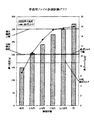
以下、上記穿通器具の好ましい実施形態について図を用いて説明する。図1は穿通器具の構成を説明する図である。図2は各種実験結果と設定値との関係を説明する図である。図3は穿通器具の比較例の断面形状を説明する図である。
【0033】
図1に於いて、穿通器具Aは、シャフト部1と、このシャフト部1に連なる作業部2と、シャフト部1に固定され治療の際に医師の手に把持されて操作され、或いはハンドピースに装着されて操作されるハンドル3とを有して構成されている。
【0034】
作業部2は先端部2aから所定の長さ範囲に、同図(b)に示すように断面が円弧4aと弦4bからなり、円弧4aを構成する円の径をDとし、弦4bの垂直二等分線に於ける円弧4aと弦4bとを結ぶ線分の長さをLとしたとき、この線分の長さLが5/8D以上に設定された穿通部4が形成されている。また穿通部4とシャフト部1の間には、断面形状が穿通部4に於ける断面形状に限定されることのない元部2bが形成されている。
【0035】
穿通部4の長さ範囲は5mmに設定されている。この長さ範囲5mmは実験及び経験的に得られた値である。即ち、根管を治療するに際し特に大きな負荷が作用するのは先端から5mmまでの範囲であり、従って、穿通部4の長さは5mmあれば充分である。そしてこの穿通部4に対応する部分の断面形状が上記の如く、Lの長さが5/8D以上の寸法を持って形成されている。
【0036】
作業部2に於ける穿通部4以外の部分、即ち、元部2bの断面形状は特に限定するものではない。このため、元部2bの断面形状は穿通部4と同様にLの長さが5/8D以上の寸法を持って形成されていても良く、5/8D以下の寸法を持って形成されていても良い。しかし、元部2bは断面積を小さくして曲げ剛性を小さくし、これにより、作業部2の長さ方向の曲げ剛性を全長にわたって穿通部4の曲げ剛性と大きく変化させることがないようにすることが好ましい。
【0037】
穿通部4及び元部2bからなる作業部2は同サイズのKファイルと同等の捩れ角を持って捻っても良い。即ち、穿通部4を根管内に充満している内容物に刺し通して筋道を付ける場合、穿通器具Aを押し引き操作することで実現するが、このとき、穿通部4と内容物との接触摩擦を可及的に小さくすることが好ましい。従って、リードの長い捻じりであれば特別に問題になることはない。また、押し引きと共に回転操作すればリードは短くても問題ない。また、作業部2の元部2bに行くに従って捩れ角を大きくすることで、良好なフレキシビリティを得ることが期待できる。さらに、穿通部である先端から5mmの部分の捩れ角を他の部分よりはっきりと小さくすることにより、回転操作させた際の食い込みを防止することができる。
【0038】
穿通部4の縮径率(テーパ角度)は同サイズのKファイルのテーパ角度と略等しく設定されている。しかし、穿通部4のテーパをKファイルのテーパよりも小さくすることで、先端部2aの近傍に於ける曲げ剛性を大きくすることが可能である。
【0039】
本実施例に於いて、作業部2は同サイズのKファイルと同等のサイズの材料を用いて形成され、且つKファイルと略等しい捩れ角を持って捩じられている。
【0040】
穿通部4に於ける断面形状は、穿通部4によって根管内に充満した内容物を刺し通す際の抵抗による負荷を想定した実験(根管挿入抵抗比較試験)と、作業部2に対する曲げ実験(曲げ比較試験)を行なった結果から得ている。
【0041】
根管挿入比較試験は、直線根管模型(#15、2/100テーパ)にイソプレン系ゴムからなる根管充填用ポイントを8mm部位まで充填し、テストピースが充填物に当接した後、3mm挿入する場合の抵抗を測定して比較した。テストピースとしては、穿通部4の断面形状とし弦と円弧を結ぶ線分の長さLを1/2D〜15/16Dの範囲内で種々設定したもの、円形、Kファイル#10とした。
【0042】
尚、以下の表1,表2に於いて例えば5/8円と記載されているのは、弦4bと円弧4aを結ぶ線分の長さLが5/8Dに設定されたものを示しており、他のテストピースでも同様である。
【0043】
また医師の聞き取り調査や他の調査の結果、根管に充満した内容物を刺し通す際の挿入抵抗の上限を、比較したKファイル#10に於ける抵抗値の150%として設定した。これは、現実の治療における抵抗の大きさは、内容物刺通の際ではなく石灰化や湾曲による狭窄部に突き当たった際に感じるものであり、よって内容物刺通の抵抗を150%と設定してもまだ太すぎることは無いという現場の多数の医師の意見による。この設定値を図2に挿入抵抗上限として記載した実線で示す。
【0044】
根管挿入比較試験の結果得られた数値を表1及び図2の棒グラフに示す。
【0045】
【表1】

この結果、Kファイル#10の挿入抵抗値が204.1g(図2に10K挿入抵抗として記載した点線で示す)であり、設定された上限の抵抗値は306.15gとなる。この数値は、比較実験した断面が円形のものを除いた全てが満足している。ちなみに、従来の技術で説明した焼入硬化したKファイル#10であっても、挿入抵抗は当然図2に示すKファイル#10の挿入抵抗値と同じである。
【0047】
曲げ比較試験は、ISO規格に準じた方法を採用してテストピースの先端(穿通部4の先端部)から3mmの部分の曲げトルクを測定して比較した。テストピースとしては、根管挿入比較試験に用いたテストピースと同一の断面を持ったものを用いた。
【0048】
曲げトルクの値は充分に大きいことが好ましく、比較対象となるKファイル#10の曲げトルクの120%の値を下限として設定した。ここでトルクを120%に設定したのは、従来のKファイルの曲げ強さの20%程度強ければ、根管の内容物を充分穿通して道筋をを付け得るとの現場の多数の医師の意見によるものである。この設定値を図2に曲げトルク下限として記載した実線で示す。
【0049】
曲げ比較試験の結果得られた数値を表2及び図2の折れ線グラフに示す。
【0050】
【表2】
Kファイル#10の曲げトルクの値が8.7g-cm(図2に10K曲げトルクとして記載した点線で示す)であり、設定された下限の曲げトルクは10.4g-cmとなる。この数値は断面形状が半円のテストピースを除く全てが満足している。ちなみに従来の焼入硬化したKファイル#10は12.7g-cmであるのでLが3/4Dのものに相当する。
【0052】
上記各試験の結果、根管挿入抵抗試験と曲げ比較試験に夫々設定された限度を満足する断面形状は、弦4bと円弧4aを結ぶ線分の長さLが5/8D〜15/16Dの範囲である。しかし、前記長さLが15/16Dよりも長くとも、弦4bと円弧4aからなる形状であれば前記各限度を満足することが可能である。
【0053】
従って、穿通部4の断面形状は、円弧4aと弦4bとからなり(円を除く)、弦4bと円弧4aとを結ぶ線分の長さLが5/8D以上である。
【0054】
また穿通器具Aは、挿入抵抗の値と曲げ剛性とがバランスのとれたものであることが好ましい。この点を考慮した場合、穿通部4に於ける断面形状は、弦4bと円弧4aとを結ぶ線分の長さLが3/4D程度であることが好ましい。
【0055】
次に、図3により穿通器具Aに於ける穿通部4の断面形状の比較例について説明する。図に示す各例は、弦が2つ、或いは3つと、長さが円弧を構成する円の1/2以上ある円弧との組み合わせによって構成したものである。
【0056】
同図(a)は弦4bの端点を起点に弦4cを設けたものであり、同図(b)は弦4c,4dを設けたものであり、更に同図(c)は上下に平行した2つの弦4e(3/16削除した面)と、弦4f(1/16削除した面)を設けたものである。 上記各断面を持った穿通器具Aを構成してテストピースとし、夫々先端から3mm部の曲げトルクを測定したところ、同図(a)のテストピースでは 13.08g-cm、同図(b)のテストピースでは12.9g-cm、同図(c)のテストピースでは13.5g-cmであった。このように、厚さLが5/8以上あり、弧4aが半円以上である場合は大きな曲げ力の低下にならず、切味を向上できることが判明した。これは特に石灰化した根管の穿通に良い結果を示した。
【0057】
即ち、弦の垂直二等分線における弦と弧、弦と弦との間の線分の内の最短のものの長さが円の直径の5/8以上であれば曲げ強さを保持し得る。また円弧が元の円の1/2以上残ることでエッジの角も90度以上となるので強さを保つことが可能である。更に、1/2以上の円周面となり凹凸が少ないので、器具を刺し通す際の抵抗も小さく、スムーズに刺し通すことが可能である。
【0058】
次に、穿通器具Aを製造する際の手順について簡単に説明する。先ず、生還線引き加工して組織をファイバー状に伸長させたオーステナイト系ステンレスの素材を目的の穿通器具Aに必要な長さに切断し、全長にわたって研削して、テーパー状円錐柱ワークを形成した後、その外側を所定平面(弦4bに相当する平面)に研削等の手段で削除して、元部2bの断面形状に形成すると共に、穿通部4の断面形状を前述した実施例の形状に形成する。
【0059】
本発明では穿通器具Aに於ける穿通部4を構成する際の研削手段や方法を限定するものではなく、最終製品として円弧4aと弦4bが形成されれば良いことは当然である。
【0060】
先細テーパー状円錐柱を製作する場合、切削加工、研削加工、転造加工、スエージング加工などの加工法を採用することが可能であり、特に、転造加工やスエージング加工では、加工硬化を期待することが可能である。また研削加工ではセンタレス研削や他の方法を採用することが可能である。このとき、研削方向は線材に対し略直角方向に、直角以外の角度で交差する方向に、線材の長手方向の何れかとする。また、特公昭58−52782号に記載した従来の研削方法のように、溝(V、U溝等)に線材を置いて回転させながら砥石で研削する方法を用いても良い。
【0061】
弦4bを構成する面は切削加工、研削加工等で加工することが可能である。研削加工では、砥石の外周に押し付けて研削した面を持った治具と砥石との間に上記円錐柱を入れて研削することが可能である。また研削方向は線材に対し略直角方向に、直角以外の角度で交差する方向に、線材の長手方向の何れかとする。また、前記した特公昭58−52782号に記載した従来の研削方法のように、溝(V、U溝等)に先細テーパー円錐柱材を入れてその上で砥石で研削する方法を用いても良い。
【0062】
本実施例のように、予め設定された捩れ角を持って捩れている穿通部4を形成する場合、円弧4aと弦4bをバイスによって挟持し、この状態で捩じりを加えて穿通器具Aを製造する。このとき、穿通部4の円弧4aと弦4bをバイスによって挟持するため、製造された穿通部4の断面に於ける円弧4aは厳密な意味で円弧とはいえない可能性があり、同様に弦4bも厳密な意味で直線とはいえない可能性がある。
【0063】
しかし、上記問題は捩じり加工に必然的に付随するものであり、このような製造過程で変形が発生した場合であっても、円弧4aの範疇に含まれ、同様に弦4bの範疇に含まれるものとする。同様に捩じり過程で、バイスによって挟持した以外の部分で捩じりに伴う潰れ等の変形が生じた場合であっても、この変形に関わらず穿通部4は円弧4aと弦4bとによって構成されたものとする。
【0064】
前述の実施例では、材料としてオーステナイト系ステンレスを用いた場合を説明したが、材料としては形状記憶機能を有するニッケル−チタン合金を用いても良い。
【0065】
この場合、加工工程と、熱処理工程を選択的に設定することで、シャフト部1及び作業部2を超弾性範囲を使用することも可能である。
【0066】
刺し通す際の抵抗を低減させるために、円弧4aの表面を鏡面に仕上げることが好ましい。また円弧4aと弦4bの接続点が複数形成される場合、選択された接続点を潰しておくことが好ましい。この場合、残された接続点が切刃として機能し、他の接続点は切刃としての機能を有することがない。
【0067】
またシャフト部1に接続するハンドル3は必ずしも必要なものではなく、ハンドピースやエンジン等の機械に装着する場合には、対応する機械にチャッキングし得るように構成することが必要である。
【0068】
また、穿通部4の全長にわたって曲げ強度或いは曲げ剛性の均一化をはかるために、穿通部4に於けるLの値を変化させることが好ましく、且つテーパを変化させることが好ましい。これらの変化率は一義的に限定するものではなく、穿通器具Aの太さやテーパ角等の条件によって選択的に設定することが好ましい。なお、通常のファイルは2/100テーパー率で製作されているが、本発明の器具は、2/100テーパー率又はそれより大小のテーパー率で製作して差し支えない。
【0069】
また、これまで、本発明の器具は穿通器具として述べてきたが、本発明の器具は、主に回転・ツイスト運動を行う機械式切削等に用いても効果を発揮する。即ち、従来の機械用根管拡大器具は切れすぎて食い込んでしまうため、様々な方法で対処しているが、本発明の器具はエッジが鈍く(90度以上)切れ刃が少ないので、食い込みにくく好適である。さらに、本発明のものを機械用切削に用いる場合、やや太目の先端径(0.15mm以上)のものを使用することが好ましい。径が太いと円周面が多くなるので、安定した切削が可能になるからである。
【0070】
【発明の効果】
以上詳細に説明したように本発明に係る穿通器具では、根管治療を開始するに際し、根管に充満した歯髄等の内容物に差し込まれ、他の根管治療器具であるリーマやKファイル,Hファイルを導くために有効な道筋を付けることが出来る。そして、内容物に挿入したときの抵抗による負荷や先端が根管壁に接触したときの負荷が作用しても、曲げ強度が大きく、且つ曲げ剛性が大きいため、曲げ変形を小さくすることが出来る。このため、操作する医師に抵抗の変化を敏感に伝達することが可能となり、医師の操作性が向上して消耗の度合いを軽減することが出来る。従って、器具のコストを低減することが出来る。
【0071】
また根管内の内容物に道筋を付けることを目的とし、必要最小限の凹凸であるため、根管刺通の抵抗は小さくそれでいて石灰化壁突起部等の切削も可能である。このため、内容物の内部に必要な深さの道筋を容易に付けることが出来、根管治療の際に余分な手間を掛けることなく円滑な治療を実現することが出来る。このため、治療コストを軽減することが出来る。
【図面の簡単な説明】
【図1】穿通器具の構成を説明する図である。
【図2】各種実験結果と設定値との関係を説明する図である。
【図3】穿通器具に於ける穿通部の断面形状の比較例を説明する図である。[0001]
BACKGROUND OF THE INVENTION
The present invention relates to a dental root canal treatment instrument, and in particular, at the time of starting root canal treatment, the contents filled in the root canal are pierced, and sometimes a protrusion from a hard root canal wall is cut. Thus, the present invention relates to a dental root canal treatment instrument for providing a path for guiding other dental root canal treatment instruments.
[0002]
[Prior art]
In root canal treatment in dentistry, the calcified root canal wall up to the apex is cut, and the new surface of the root canal wall is exposed by removing the cutting chips and the contents filled in the root canal. Is done. When performing such treatment, the doctor can select the best treatment for the target treatment from the reamer, K file, H file, etc. with various sizes, and directly operate by hand. Or it is common to grasp | ascertain the stage of a treatment by the touch at the time of operation by operating by hand indirectly through a handpiece.
[0003]
The reamer is formed by twisting a rod-like material with a triangular or quadrangular cross section at a small angle, and has a function of cutting the root canal wall mainly by rotating and removing the contents filled in the cutting waste and root canal. Have. The K file is formed by twisting a rod-like material with a triangular or square cross section at a relatively strong angle, and has a function of cutting the root canal wall mainly by pushing and pulling and removing cutting waste and contents. Have. The H file is formed by cutting a rod-shaped material into a cross-sectional shape consisting of a part of a straight line in the radial direction and a spiral curve, and is pushed and pulled to cut the root canal wall and cut chips and contents. It has the function to exclude things.
[0004]
The root canal has a tapered and curved shape that becomes thinner as it approaches the apex, and this curved shape varies greatly depending on the person. For this reason, root canal treatment devices such as reamers, K-files, and H-files have a high degree of flexibility so that they can follow a root canal (root canal wall) that is tapered and has a different curved shape for each patient. Configured.
[0005]
The root canal treatment instrument such as the reamer, the K file, and the H file is preferably manufactured using austenitic stainless steel that does not break or break during treatment and does not generate rust. The applicant of the present application uses various materials such as austenitic stainless steel that are cold-drawn to stretch the tissue into fibers, thereby realizing high hardness and high bending strength. Has the technology to manufacture instruments.
[0006]
On the other hand, the inside of the root canal is filled with contents (dental pulp) composed of nerves, blood vessels, and lymphatic vessels, and sometimes it is hardened. Thus, at the time of starting treatment, the curved shape of the root canal and the stenosis state due to calcification of the root canal wall are not in a state where the naked eye can visually recognize. Therefore, when root canal treatment is started with a root canal treatment device such as a reamer, K file, or H file, this content is placed on the distal end portion of the root canal treatment device pierced with the contents in the root canal. The resistance at the time of piercing acts as a load, and further, when the tip portion that has passed through the contents comes into contact with the root canal wall, a load according to the force applied during the operation acts.
[0007]
The timing when the tip of the root canal treatment instrument contacts the root canal wall changes depending on conditions such as the state of curvature of the root canal and stenosis due to calcification of the root canal wall. It is difficult to adjust the force applied when operating the instrument to be small, and a large load acts on the tip portion at this moment. The load is often more than the allowable load of the root canal treatment instrument, and there is a problem that the tip portion is permanently deformed and cannot be used. In some cases, the tip portion may be folded, which is more serious than the consumption of the root canal treatment instrument.
[0008]
In particular, since the treatment is performed in a state where the contents are full and the root canal wall cannot be visually recognized, it is natural to give priority to safety. For this reason, in order to avoid the problem of folding, if a root canal treatment device having a larger allowable load than the size that can be originally used is used, the root canal wall is often bound to that extent. The problem arises that the purpose of creating a path cannot be achieved. In addition, when a small-sized device is used, the distal end portion of the root canal treatment device is often deformed, resulting in a problem that a plurality of sizes of the root canal treatment device are consumed during a single treatment.
[0009]
The above problem is that the root canal is filled with the content that has been filled in the root canal, and an effective route is first introduced to guide the root canal treatment instrument. The optimal reamer, K file, H It can be solved by selecting a file. In order to exert such a function, at least the tip portion of the root canal treatment instrument should have a strength that can withstand the load caused by the resistance of the contents filled in the root canal and the load when colliding with the root canal wall. good.
[0010]
Recently, there has been provided a therapeutic device for use in laying a path to the contents filled in the root canal at the start of root canal treatment. This treatment instrument is constituted by adopting carbon steel as a material and quenching. In this treatment instrument, the bending strength can be increased as compared with the material made of austenitic stainless steel, so even if the contents are filled and hardened in the root canal, it is pushed and pulled. By rotating, it is possible to attach a path for guiding other root canal treatment instruments to the root canal.
[0011]
When the reamer and file are manufactured, the round bar (line) is directly ground with an inclined plane corresponding to the taper to form a tapered rectangular line having a cross-sectional shape such as a square, a triangle, or a rectangle. When manufacturing the H file, the round line is ground as it is with a single stroke.
[0012]
[Problems to be solved by the invention]
As described above, when using a reamer, K file, or H file at the start of root canal treatment, excessive bending or permanent deformation due to the load of the contents filled in the root canal and the load when contacting the root canal wall There is a problem that it occurs and is consumed. In addition, there is a problem that a treatment time is increased by using or depleting a root canal treatment instrument more than necessary for treatment, thereby increasing the treatment cost. In addition, these therapeutic devices may not even be able to attach a path to the apex.
[0013]
Moreover, in the treatment instrument which consists of carbon steel which solved the said problem, quenching process is essential. However, because the quenching part is extremely thin and the heat capacity is small, it is not easy to raise the whole to a uniform temperature, it is difficult to exert a uniform strength over the entire length, and the uniformity of many therapeutic instruments There is a problem that it is difficult to hold. This can cause serious problems that sometimes include brittle things that break in the root canal. In addition, due to the characteristics of the carbon steel material, it is easy to rust, and once a treatment instrument that has been used is sterilized by autoclaving, it cannot be used due to corrosion. There is a problem that even if rust is removed, the required strength cannot be exhibited. For this reason, what was used once will be discarded, and there exists a problem that an instrument cost becomes high.
[0014]
An object of the present invention is to provide a dental root canal treatment instrument capable of reliably providing a route for guiding another root canal therapy instrument at the start of root canal therapy, and a method for reliably and inexpensively manufacturing the instrument. There is.
[0015]
[Means for Solving the Problems]
In order to obtain a dental root canal treatment instrument that solves the above problems, the present inventors have conducted various experiments. As a result, it has been found that the following elements are necessary to provide a route for leading the reamer, K file, and H file to the contents filled in the root canal.
[0016]
The first element is that at least the tip portion can exhibit a bending strength that can resist a load when being pushed into the contents, and further, when the root canal is narrowed due to the curved state or calcification of the root canal Even when the root canal wall is unexpectedly contacted at this portion, it has a bending rigidity capable of withstanding the load at this time.
[0017]
As described above, since the object can be achieved by pushing the tip portion, it is necessary that the strength is sufficiently larger than the strength of the K file on the basis of the bending strength of the K file performing the same operation. It is.
[0018]
In order to improve the bending strength, it is necessary to select a material having a high strength. However, materials that require heat treatment are susceptible to variations due to heat treatment, and materials that are prone to rust cannot be sterilized in advance, and there are problems such as repeated use and limited storage days. Therefore, it is preferable to use austenitic stainless steel that does not cause rusting, and this material is cold drawn to elongate the structure into a fiber shape and exhibits strength against bending and strength It is desirable to use
[0019]
And bending rigidity can be improved by setting a cross-sectional shape using the material of the austenitic stainless steel which carried out the cold drawing process.
[0020]
The second element is that the contents filled in the root canal are easily moved. In this case, it is not always necessary to exclude the contents to the outside, and it is only necessary to move the path within the root canal. In order to move the contents in the root canal, it is necessary that there is a gap through which the contents can move between the distal end portion of the dental root canal treatment instrument and the root canal wall.
[0021]
The third factor is that resistance when piercing the contents filled in the root canal is as small as possible. In this case, it is necessary that the surface of the part pierced inside the contents has little unevenness. In particular, when piercing the contents, it is necessary to convey a delicate feeling to the operating doctor when the tip comes into contact with a foreign substance such as a root canal wall. For this reason, although it is preferable that resistance is small, it is necessary to make a doctor feel some resistance.
[0022]
The fourth element is to have a minimum cutting edge capable of cutting and passing through a narrowed portion due to a curved state of the root canal or calcification. In the first place, since it is a device for making a path, it is required to be very thin, and the diameter of the tip portion is preferably in the range of 0.06 mm to 0.10 mm. For this reason, there is sufficient flexibility to bend along the curved root canal. Therefore, it is necessary to have a strong cutting edge capable of cutting the hardened contents and cutting some protrusions of the root canal wall.
[0023]
Therefore, a dental root canal treatment instrument according to the present invention satisfying each of the above elements is a dental root canal treatment instrument having a shaft portion and a working portion connected to the shaft portion,The working part is spirally twisted from the tip to the base part, andAt least the cross-sectional shape from the tip of the working part to a predetermined length range consists of one arc and one chord, and the length of the line segment connecting the chord and arc in the perpendicular bisector of the chord is It is characterized by being 5/8 or more of the diameter of the circle constituting the arc.
[0024]
In the dental root canal treatment instrument, an effective path can be attached to the contents filled in the root canal when starting root canal treatment. (The dental root canal treatment instrument according to the present invention is hereinafter referred to as “penetration instrument” for the purpose of attaching a path to the root canal)
[0025]
In the penetrating device, the cross-sectional shape in a predetermined length range from the tip of the working unit is formed of an arc and a chord, and the length of a line segment connecting the arc and the chord is 5/8 or more of a circle constituting the arc. By doing so, it is possible to obtain a cross-section having a cross-sectional area larger than the cross-sectional area of the K file, which is a root canal treatment instrument that has been initially pierced with the contents in the treatment of the root canal, and a cross-sectional second moment.
[0026]
For this reason, sufficiently high bending strength and bending rigidity can be obtained compared with the K file.
[0027]
Further, by constituting the cross-sectional shape with an arc and a chord, the contents can be easily moved in the root canal.
[0028]
In particular, an edge formed at a connection portion between a string and an arc can be functioned as a cutting blade. For this reason, when a part of the root canal wall calcified in the root canal exists as a protrusion, the protrusion can be excised by rotating the penetrating instrument.
[0029]
As described above, in the present invention, although the distal end portion of the penetrating device is preferably circular in terms of bending strength, the cross-sectional shape is a combination of a chord and an arc in consideration of the function as the cutting blade. It is said.
[0030]
The manufacturing method according to the present invention is a dental root canal treatment instrument having a shaft portion and a working portion connected to the shaft portion, wherein at least a cross-sectional shape from the tip of the working portion to a predetermined length range is an arc and a chord. In the manufacturing method of a dental root canal treatment instrument consisting of: at least a cylinder with a predetermined taper taper in a predetermined length range from the tip of the working part, and then a side surface of the predetermined length range from the tip,The cross section consists of one arc and one chord, and the length of the line segment connecting the chord and the arc in the perpendicular bisector of the chord is 5/8 or more of the diameter of the circle constituting the arc Delete in a predetermined plane, and then spirally formIt is characterized by this.
[0031]
By manufacturing the penetrating device by the above method, it is possible to provide a penetrating device that is inexpensive and has a certain quality.
[0032]
DETAILED DESCRIPTION OF THE INVENTION
Hereinafter, a preferred embodiment of the penetrating device will be described with reference to the drawings. FIG. 1 is a diagram illustrating the configuration of the penetrating device. FIG. 2 is a diagram for explaining the relationship between various experimental results and set values. Figure 3 shows the penetration deviceComparisonIt is a figure explaining the cross-sectional shape of an example.
[0033]
In FIG. 1, a penetrating device A includes a shaft portion 1, a working
[0034]
The working
[0035]
The length range of the
[0036]
A portion other than the penetrating
[0037]
Working
[0038]
The diameter reduction rate (taper angle) of the penetrating
[0039]
In the present embodiment, the working
[0040]
The cross-sectional shape of the
[0041]
In the root canal insertion comparison test, a straight root canal model (# 15, 2/100 taper) was filled up to 8mm with root canal filling points made of isoprene-based rubber, 3mm after the test piece abuts the filling. The resistance when inserting was measured and compared. As the test piece, the cross-sectional shape of the penetrating
[0042]
In Tables 1 and 2 below, for example, 5/8 yen indicates that the length L of the line segment connecting the chord 4b and the arc 4a is set to 5 / 8D. The same applies to other test pieces.
[0043]
In addition, as a result of doctor interviews and other investigations, the upper limit of insertion resistance when the contents filled in the root canal were pierced was set as 150% of the resistance value in the compared
[0044]
The numerical values obtained as a result of the root canal insertion comparison test are shown in Table 1 and the bar graph of FIG.
[0045]
[Table 1]
As a result, the insertion resistance value of the
[0047]
In the bending comparison test, a method according to the ISO standard was adopted, and the bending torque of a
[0048]
The value of the bending torque is preferably sufficiently large, and a value of 120% of the bending torque of the
[0049]
Numerical values obtained as a result of the bending comparison test are shown in Table 2 and the line graph of FIG.
[0050]
[Table 2]
The value of the bending torque of the
[0052]
As a result of each of the above tests, the cross-sectional shape satisfying the limits set in the root canal insertion resistance test and the bending comparison test has a length L of a line segment connecting the chord 4b and the arc 4a of 5 / 8D to 15 / 16D. It is a range. However, even if the length L is longer than 15 / 16D, it is possible to satisfy the above-mentioned limits as long as the shape is composed of the chord 4b and the arc 4a.
[0053]
Accordingly, the cross-sectional shape of the penetrating
[0054]
Further, it is preferable that the penetrating instrument A has a balanced value of insertion resistance and bending rigidity. In consideration of this point, the length L of the line segment connecting the chord 4b and the arc 4a is preferably about 3 / 4D in the cross-sectional shape in the penetrating
[0055]
Next, the cross-sectional shape of the
[0056]
The figure (a) is provided with the
[0057]
That is, the bending strength can be maintained if the length of the shortest of the chords and arcs in the vertical bisector of the chord and the line segment between the chords and the chord is 5/8 or more of the diameter of the circle. . In addition, since the arc remains at half or more of the original circle, the edge angle becomes 90 degrees or more, so that the strength can be maintained. Furthermore, since it has a circumferential surface of 1/2 or more and less irregularities, resistance when piercing the instrument is small, and it can be smoothly pierced.
[0058]
Next, a procedure for manufacturing the penetrating instrument A will be briefly described. First, after cutting the austenitic stainless steel material, which has been stretched into a fiber shape by life-drawing, to the length required for the target penetrating device A, and grinding the entire length to form a tapered conical column workpiece The outer side is deleted to a predetermined plane (a plane corresponding to the chord 4b) by means such as grinding to form the cross-sectional shape of the
[0059]
In the present invention, the grinding means and the method for forming the penetrating
[0060]
When producing a tapered tapered conical column, it is possible to adopt machining methods such as cutting, grinding, rolling, swaging, etc. Especially in rolling and swaging, work hardening is required. It is possible to expect. In addition, centerless grinding or other methods can be employed in the grinding process. At this time, the grinding direction is any one of the longitudinal directions of the wire in a direction substantially perpendicular to the wire and a direction intersecting at an angle other than a right angle. Further, as in the conventional grinding method described in Japanese Patent Publication No. 58-52782, a method of grinding with a grindstone while putting a wire in a groove (V, U groove, etc.) and rotating it may be used.
[0061]
The surface constituting the string 4b can be processed by cutting, grinding, or the like. In the grinding process, it is possible to perform grinding by inserting the above-mentioned conical column between a jig having a ground surface pressed against the outer periphery of the grindstone and the grindstone. The grinding direction is any of the longitudinal directions of the wire in a direction substantially perpendicular to the wire and a direction intersecting at an angle other than a right angle. Alternatively, as in the conventional grinding method described in Japanese Patent Publication No. 58-52782, a method in which a tapered tapered columnar material is put in a groove (V, U groove, etc.) and then ground with a grindstone may be used. good.
[0062]
When the penetrating
[0063]
However, the above problem is inevitably associated with the twisting process, and even when deformation occurs in such a manufacturing process, it is included in the category of the arc 4a and similarly in the category of the string 4b. Shall be included. Similarly, even when deformation such as crushing due to torsion occurs in a portion other than the portion sandwiched by the vice during the twisting process, the penetrating
[0064]
In the above-described embodiment, the case where austenitic stainless steel is used as the material has been described. However, a nickel-titanium alloy having a shape memory function may be used as the material.
[0065]
In this case, it is also possible to use the superelastic range for the shaft portion 1 and the working
[0066]
In order to reduce the resistance at the time of piercing, it is preferable to finish the surface of the arc 4a into a mirror surface. Arc 4a and string 4bWhen a plurality of connection points are formed, it is preferable to collapse the selected connection points. In this case, the remaining connection points function as cutting edges, and other connection points do not have a function as cutting edges.
[0067]
Further, the
[0068]
Further, in order to make the bending strength or bending rigidity uniform over the entire length of the penetrating
[0069]
Further, although the instrument of the present invention has been described as a penetrating instrument so far, the instrument of the present invention is effective even when used for mechanical cutting or the like that mainly performs a rotation / twist motion. That is, since the conventional root canal enlargement device for machines is cut too much and bites in, various methods are used. However, the device of the present invention has a dull edge (90 degrees or more) and few cutting edges, so it is difficult to bite. Is preferred. Furthermore, when using the thing of this invention for machine cutting, it is preferable to use a thing with a somewhat large tip diameter (0.15 mm or more). This is because if the diameter is large, the circumferential surface increases, so that stable cutting is possible.
[0070]
【The invention's effect】
As described above in detail, in the penetrating device according to the present invention, when starting root canal treatment, the root canal is filled with contents such as dental pulp filled with the root canal, and other root canal treatment devices such as reamers and K files, An effective path to guide the H file can be created. Even when a load due to resistance when inserted into the contents or a load when the tip contacts the root canal wall acts, the bending deformation is large and the bending rigidity is large, so that bending deformation can be reduced. . For this reason, it becomes possible to transmit the change of resistance sensitively to the doctor who operates, the operability of the doctor is improved, and the degree of wear can be reduced. Therefore, the cost of the instrument can be reduced.
[0071]
In addition, the purpose is to provide a path to the contents in the root canal, and since it is the necessary minimum unevenness, the resistance of root canal piercing is small, and cutting of the calcified wall projections and the like is possible. For this reason, the path | route of the required depth can be easily attached to the inside of a content, and smooth treatment can be implement | achieved without taking an extra effort at the time of root canal treatment. For this reason, the treatment cost can be reduced.
[Brief description of the drawings]
FIG. 1 is a diagram illustrating a configuration of a penetrating device.
FIG. 2 is a diagram illustrating the relationship between various experimental results and set values.
FIG. 3 shows the cross-sectional shape of the penetration part in the penetration device.ComparisonIt is a figure explaining an example.
Claims (2)
Priority Applications (4)
| Application Number | Priority Date | Filing Date | Title |
|---|---|---|---|
| JP35792799A JP4214284B2 (en) | 1999-12-16 | 1999-12-16 | Dental root canal treatment instrument |
| DE60030398T DE60030398T2 (en) | 1999-12-16 | 2000-12-15 | Dental instrument for the treatment of the root canals |
| US09/736,269 US6524104B2 (en) | 1999-12-16 | 2000-12-15 | Dental instrument for root canal therapy |
| EP00127599A EP1108396B1 (en) | 1999-12-16 | 2000-12-15 | Dental instrument for root canal therapy |
Applications Claiming Priority (1)
| Application Number | Priority Date | Filing Date | Title |
|---|---|---|---|
| JP35792799A JP4214284B2 (en) | 1999-12-16 | 1999-12-16 | Dental root canal treatment instrument |
Publications (2)
| Publication Number | Publication Date |
|---|---|
| JP2001170076A JP2001170076A (en) | 2001-06-26 |
| JP4214284B2 true JP4214284B2 (en) | 2009-01-28 |
Family
ID=18456657
Family Applications (1)
| Application Number | Title | Priority Date | Filing Date |
|---|---|---|---|
| JP35792799A Expired - Lifetime JP4214284B2 (en) | 1999-12-16 | 1999-12-16 | Dental root canal treatment instrument |
Country Status (4)
| Country | Link |
|---|---|
| US (1) | US6524104B2 (en) |
| EP (1) | EP1108396B1 (en) |
| JP (1) | JP4214284B2 (en) |
| DE (1) | DE60030398T2 (en) |
Families Citing this family (10)
| Publication number | Priority date | Publication date | Assignee | Title |
|---|---|---|---|---|
| US20040058298A1 (en) * | 2002-09-25 | 2004-03-25 | Dennis Brava | Self centering endodontic files |
| WO2004086628A1 (en) * | 2003-03-25 | 2004-10-07 | Fujitsu Limited | Encoder circuit and a/d converter circuit |
| JP5286079B2 (en) | 2005-05-17 | 2013-09-11 | イエダ リサーチ アンド ディベロップメント カンパニー リミテッド | Low friction coating for dental and medical devices |
| US8047842B2 (en) * | 2008-08-18 | 2011-11-01 | Johnson William B | Reciprocal reverse rotation endodontic file |
| PL2401981T3 (en) * | 2009-02-27 | 2018-01-31 | Mani Inc | Gutta-percha remover |
| US9155595B2 (en) * | 2010-06-21 | 2015-10-13 | Yeda Research And Development Co. Ltd. | Endodontic files and method of preparation thereof |
| US11446413B2 (en) | 2014-01-06 | 2022-09-20 | Yeda Research And Development Co. Ltd. | Attenuation of encrustation of medical devices using coatings of inorganic fullerene-like nanoparticles |
| CN105287025B (en) * | 2015-10-26 | 2017-11-07 | 于金华 | A kind of personalized preparation method of dentistry root canal ultrasonic file |
| US10561475B2 (en) * | 2016-03-15 | 2020-02-18 | Essential Dental Systems, Inc. | Non-circular endodontic instruments |
| CN113197685B (en) * | 2020-01-31 | 2022-08-09 | 马尼株式会社 | Dental root canal treatment instrument |
Family Cites Families (4)
| Publication number | Priority date | Publication date | Assignee | Title |
|---|---|---|---|---|
| JPS5852782B2 (en) | 1981-09-24 | 1983-11-25 | 株式会社 松谷製作所 | Grinding method for dental ultra-fine square cutting tools |
| US4934934A (en) * | 1988-11-04 | 1990-06-19 | Quality Dental Products, Inc. | Dental file/reamer instrument |
| US5527205A (en) * | 1991-11-05 | 1996-06-18 | Tulsa Dental Products, L.L.C. | Method of fabricating an endodontic instrument |
| US5762497A (en) * | 1996-03-07 | 1998-06-09 | Tulsa Dental Products | Endodontic dental instrument |
-
1999
- 1999-12-16 JP JP35792799A patent/JP4214284B2/en not_active Expired - Lifetime
-
2000
- 2000-12-15 DE DE60030398T patent/DE60030398T2/en not_active Expired - Lifetime
- 2000-12-15 US US09/736,269 patent/US6524104B2/en not_active Expired - Lifetime
- 2000-12-15 EP EP00127599A patent/EP1108396B1/en not_active Expired - Lifetime
Also Published As
| Publication number | Publication date |
|---|---|
| JP2001170076A (en) | 2001-06-26 |
| US20010034005A1 (en) | 2001-10-25 |
| EP1108396A2 (en) | 2001-06-20 |
| US6524104B2 (en) | 2003-02-25 |
| EP1108396A3 (en) | 2003-01-08 |
| DE60030398D1 (en) | 2006-10-12 |
| EP1108396B1 (en) | 2006-08-30 |
| DE60030398T2 (en) | 2007-08-30 |
Similar Documents
| Publication | Publication Date | Title |
|---|---|---|
| US7731498B2 (en) | Endododontic file with multi-tapered flutes | |
| US7669332B2 (en) | Method for manufacturing endodontic reamers and files | |
| US6514076B1 (en) | Precipitation hardenable stainless steel endodontic instruments and methods for manufacturing and using the instruments | |
| US20050266375A1 (en) | Endodontic instrument having notched cutting surfaces | |
| US20080050697A1 (en) | Endodontic Instruments | |
| JP4269302B2 (en) | Dental reamer | |
| US20040023186A1 (en) | Multi-tapered endodontic file | |
| EP2174616B1 (en) | Stainless steel bur | |
| JP4214284B2 (en) | Dental root canal treatment instrument | |
| JP2009279427A (en) | Sharp-pointed needle | |
| JP4042814B2 (en) | Dental root canal treatment instrument | |
| JP5547711B2 (en) | Gutta-percha remover | |
| JP4186713B2 (en) | Root canal treatment instrument and manufacturing method | |
| US20060265858A1 (en) | Endodontic instrument having notched cutting surfaces | |
| US20050069837A1 (en) | Methods for manufacturing endodontic instruments | |
| JP2002537892A (en) | Non-circular endodontic instruments | |
| JP4214285B2 (en) | Dental root canal treatment instrument and manufacturing method thereof | |
| JP2006077313A (en) | Medical needle or cutter | |
| US20080213720A1 (en) | Endodontic instruments manufactured using chemical milling | |
| JP4653071B2 (en) | Root canal boring tool | |
| Ruddle | Finishing the apical one third: endodontic considerations | |
| JP4414887B2 (en) | Dental treatment instrument with point tip and parabolic cutting groove | |
| JP4214283B2 (en) | Root canal treatment instrument | |
| Kamatham | Quick reference guide to rotary endodontic instruments-A comprehensive | |
| JP3336170B2 (en) | Dental treatment instrument and method for manufacturing dental treatment instrument |
Legal Events
| Date | Code | Title | Description |
|---|---|---|---|
| A621 | Written request for application examination |
Free format text: JAPANESE INTERMEDIATE CODE: A621 Effective date: 20061120 |
|
| A131 | Notification of reasons for refusal |
Free format text: JAPANESE INTERMEDIATE CODE: A131 Effective date: 20080624 |
|
| A977 | Report on retrieval |
Free format text: JAPANESE INTERMEDIATE CODE: A971007 Effective date: 20080624 |
|
| A521 | Request for written amendment filed |
Free format text: JAPANESE INTERMEDIATE CODE: A523 Effective date: 20080821 |
|
| RD02 | Notification of acceptance of power of attorney |
Free format text: JAPANESE INTERMEDIATE CODE: A7422 Effective date: 20080821 |
|
| TRDD | Decision of grant or rejection written | ||
| A01 | Written decision to grant a patent or to grant a registration (utility model) |
Free format text: JAPANESE INTERMEDIATE CODE: A01 Effective date: 20081014 |
|
| A01 | Written decision to grant a patent or to grant a registration (utility model) |
Free format text: JAPANESE INTERMEDIATE CODE: A01 |
|
| A61 | First payment of annual fees (during grant procedure) |
Free format text: JAPANESE INTERMEDIATE CODE: A61 Effective date: 20081017 |
|
| R150 | Certificate of patent or registration of utility model |
Ref document number: 4214284 Country of ref document: JP Free format text: JAPANESE INTERMEDIATE CODE: R150 Free format text: JAPANESE INTERMEDIATE CODE: R150 |
|
| FPAY | Renewal fee payment (event date is renewal date of database) |
Free format text: PAYMENT UNTIL: 20111114 Year of fee payment: 3 |
|
| FPAY | Renewal fee payment (event date is renewal date of database) |
Free format text: PAYMENT UNTIL: 20121114 Year of fee payment: 4 |
|
| R250 | Receipt of annual fees |
Free format text: JAPANESE INTERMEDIATE CODE: R250 |
|
| FPAY | Renewal fee payment (event date is renewal date of database) |
Free format text: PAYMENT UNTIL: 20121114 Year of fee payment: 4 |
|
| FPAY | Renewal fee payment (event date is renewal date of database) |
Free format text: PAYMENT UNTIL: 20131114 Year of fee payment: 5 |
|
| R250 | Receipt of annual fees |
Free format text: JAPANESE INTERMEDIATE CODE: R250 |
|
| R250 | Receipt of annual fees |
Free format text: JAPANESE INTERMEDIATE CODE: R250 |
|
| R250 | Receipt of annual fees |
Free format text: JAPANESE INTERMEDIATE CODE: R250 |
|
| R250 | Receipt of annual fees |
Free format text: JAPANESE INTERMEDIATE CODE: R250 |
|
| R250 | Receipt of annual fees |
Free format text: JAPANESE INTERMEDIATE CODE: R250 |
|
| R250 | Receipt of annual fees |
Free format text: JAPANESE INTERMEDIATE CODE: R250 |
|
| R250 | Receipt of annual fees |
Free format text: JAPANESE INTERMEDIATE CODE: R250 |
|
| R250 | Receipt of annual fees |
Free format text: JAPANESE INTERMEDIATE CODE: R250 |
|
| EXPY | Cancellation because of completion of term |