JP4211955B2 - Digital video processing apparatus and sub video data processing method - Google Patents
Digital video processing apparatus and sub video data processing method Download PDFInfo
- Publication number
- JP4211955B2 JP4211955B2 JP09047798A JP9047798A JP4211955B2 JP 4211955 B2 JP4211955 B2 JP 4211955B2 JP 09047798 A JP09047798 A JP 09047798A JP 9047798 A JP9047798 A JP 9047798A JP 4211955 B2 JP4211955 B2 JP 4211955B2
- Authority
- JP
- Japan
- Prior art keywords
- data
- sub
- video
- image
- pixel
- Prior art date
- Legal status (The legal status is an assumption and is not a legal conclusion. Google has not performed a legal analysis and makes no representation as to the accuracy of the status listed.)
- Expired - Fee Related
Links
Images


Classifications
-
- H—ELECTRICITY
- H04—ELECTRIC COMMUNICATION TECHNIQUE
- H04N—PICTORIAL COMMUNICATION, e.g. TELEVISION
- H04N5/00—Details of television systems
- H04N5/44—Receiver circuitry for the reception of television signals according to analogue transmission standards
- H04N5/445—Receiver circuitry for the reception of television signals according to analogue transmission standards for displaying additional information
- H04N5/44504—Circuit details of the additional information generator, e.g. details of the character or graphics signal generator, overlay mixing circuits
-
- H—ELECTRICITY
- H04—ELECTRIC COMMUNICATION TECHNIQUE
- H04N—PICTORIAL COMMUNICATION, e.g. TELEVISION
- H04N21/00—Selective content distribution, e.g. interactive television or video on demand [VOD]
- H04N21/40—Client devices specifically adapted for the reception of or interaction with content, e.g. set-top-box [STB]; Operations thereof
- H04N21/43—Processing of content or additional data, e.g. demultiplexing additional data from a digital video stream; Elementary client operations, e.g. monitoring of home network or synchronising decoder's clock; Client middleware
- H04N21/431—Generation of visual interfaces for content selection or interaction; Content or additional data rendering
- H04N21/4312—Generation of visual interfaces for content selection or interaction; Content or additional data rendering involving specific graphical features, e.g. screen layout, special fonts or colors, blinking icons, highlights or animations
Description
【0001】
【発明の属する技術分野】
本発明は、デジタルビデオ処理装置及び副ビデオデータの処理方法に関する。例えば、本発明は、テレビジョン受像機の画面に画像を表示するためのビデオ信号のデジタル処理、特に、主ビデオ信号に基づく画像の上に、副ビデオデータに基づく画像をデジタル的にスーパインポーズする技術に関する。
【0002】
【従来の技術】
テレビジョン受像機の画面表示において、一方の画像上に他方の画像をスーパインポーズしなければならないことが多々ある。従来、このようにスーパインポーズされる画像のビデオ信号は、一般的にソース番組のビデオ信号の一部として生成されていた。ところで、ソース番組のビデオ信号からだけでなく、利用者の対話的な入力によっても、スーパインポーズ用の画像のビデオ信号を生成できることが必要とされることがある。今日製造されている殆どのテレビジョン受像機は、様々なソース機器からの素材のビデオ信号、例えばビデオテープレコーダ(以下、VTRという。)、デジタルビデオディスク(以下、DVDという。)プレーヤ、ケーブル放送、デジタル衛星放送(以下、DSSという。)等のからのビデオ信号が入力されるインタフェースを備えている。また、これらのソース機器には、ムービングピクチャエキスパートグループ(Moving Picture Experts Group、以下、MPEGという。)−2のオーディオ/ビデオ圧縮規格に準拠したデジタルオーディオ信号及びビデオ信号を出力するものもある。したがって、現代のテレビジョン受像機は、デジタル入力信号を処理するとともに、所望の画像を表示するためのデジタル信号を生成する機能を有することが求められている。多くの場合、これらのデジタル信号は、アナログのモニタ受像機で表示されるために、アナログ信号に変換される。
【0003】
また、今日製造されている殆どテレビジョン受像機、及び/又はそれらとプラグで接続することができる(プラグコンパチブルな)ソース機器は、番組の表示画像上に、操作や設定のメニューをスーパインポーズして、利用者が対話的にそれらを実行させる機能を備えている。そして、利用者は、スーパインポーズされたメニュー表示を用いて、例えばキャプション(captions)又はサブタイトルの表示を選択することができる。スーパインポーズの他の用途としては、利用者が好みに合わせて調整又は設定するためのメニュー、例えばオーディオ及びビデオのレベル、ゲーム時間、難易度等の設定メニューを表示することがある。これらの設定メニューのうちの幾つかは、利用者のボタン操作に応じて変化するリニアスケールの目盛バーとして表示される。
【0004】
番組のソース機器は、デジタル情報をデータパケットとして出力する。例えば、オーディオデータと主ビデオデータは、それぞれMPEG−2のフォーマットに準拠したデータパケットとして供給される。一方、副ビデオデータ、すなわちスーパインポーズされる画像に関する情報は、幾つかのフォーマットでデータパケットとして供給される。例えば、スーパインポーズされる画像情報は、所謂DVD規格で規定されたサブピクチャフォーマットで供給される。サブピクチャフォーマットには、ヘッダブロック、画素データブロック、命令データブロックが含まれている。一般的に、ヘッダは、データの一般的な性質を識別するのに用いられる。例えば、ヘッダは、画素データが圧縮されているか、命令構造が用いられているか、どのようにデータを読み出すか等のデータフォーマットを識別するために用いられる。サブピクチャフォーマットにおいて、画素データは、カラー情報とコントラスト情報からなり、所定の圧縮技術、例えばランレング符号化によって圧縮されている。サブピクチャフォーマットにおける命令データは、副画像内のハイライトされる領域(以下、ハイライト領域という。)の位置及び大きさを識別するのに用いられ、副画像内の小さな1つ又は複数のハイライト領域は、独自のカラー値、コントラスト値等を有する。
【0005】
また、スーパインポーズの他の用途では、スーパインポーズされる副ビデオデータは、主ビデオデータのデータフォーマットとは異なるフォーマットを有する。例えば、DVB/STB方式におけるオンスクリーンディスプレイフォーマット(on-screen display format)では、副ビデオデータは、一般的には、1つのヘッダブロック及び圧縮されていない画素データブロックのみを含んでいる。更に、視聴者には見えないが、副ビデオデータは、個々の完全な画像のフィールド又はフレーム間の垂直帰線期間(vertical blanking interval:以下、VBIという。)においても用いられる。また、他の用途では、副ビデオデータは、例えばデジタル衛星放送で用いられているDSSフォーマット等の独自のフォーマットや、表示装置で用いられているアナログ信号に直接変換することができる生の画素データとしても供給される。
【0006】
従来、単一のフォーマットに互換を有するように設計されたテレビジョン受像機、例えばスーパインポーズされるビデオ情報のオンスクリーンディスプレイフォーマットを有するテレビジョン受像機が、商業的に売られていた。しかしながら、近年開発され、DVD規格で規定されたデジタルサブピクチャフォーマットに準拠したテレビジョン受像機では、スーパインポーズされるビデオデータのそれぞれのフォーマットを認識して、処理する機能を必要とする。
【0007】
【発明が解決しようとする課題】
本発明は、上述した実情に鑑みてなされたものであり、本発明の目的は、主画像上にスーパインポーズされる副画像のビデオデータを処理するためのデジタルビデオ処理装置のアーキテクチャを改良することである。この改良されたアーキテクチャのデジタルビデオ処理装置では、中央処理装置(以下、CPUという。)と、CPUによって制御される専用のハードウェアとにおいて、副ビデオデータの処理を分担するようにしている。このアーキテクチャでは、専用ハードウェアにおいて、CPUに不必要な負荷をかけることなく、すなわちCPUが他のタスクを実行できる状態で、ビデオデータを実時間で高速に処理するようにし、CPUにおいて、様々なデータフォーマットで供給される副ビデオデータの処理に対応できるように柔軟性を持たしている。
【0008】
【課題を解決するための手段】
本発明に係るデジタルビデオ処理装置は、異なる2つのデータフォーマットで供給され、主画像上にスーパインポーズされる副ビデオデータを、画像表示のための走査処理期間中に処理するデジタルビデオ処理装置において、第1のフォーマットの第1の副ビデオデータ及び第2のフォーマットの第2の副ビデオデータを記憶するメモリと、メモリに接続され、第1及び第2の副ビデオデータの第1の部分を処理するとともに、第1の副ビデオデータが第1のデータフォーマットであるか、第2の副ビデオデータが第2のデータフォーマットであるかを検出する中央処理装置と、メモリに接続され、中央処理装置に応答して、第1のデータフォーマットの第1の副ビデオデータ及び第2のデータフォーマットの第2の副ビデオデータの画素データを、画像表示のための走査処理期間中に処理して、カラーコードを生成する副ビデオプロセッサとを備える。
【0009】
また、本発明に係るデジタルビデオ処理装置は、画素データ及び命令データを含み、主画像上にスーパインポーズされる副ビデオデータを、画像表示のための走査処理期間中に処理するデジタルビデオ処理装置において、副ビデオデータの画素データ及び命令データを記憶するメモリと、メモリに接続され、副ビデオデータの命令データの第1の部分を処理する中央処理装置と、メモリに接続され、中央処理装置に応答して、副ビデオデータの命令データの第2の部分及び画素データを、画像表示のための走査処理期間中に処理する副ビデオプロセッサとを備え、副ビデオプロセッサは、画素データを記憶する第1のメモリと、主画像上にスーパインポーズされる副画像の第1の領域を定義する命令データを記憶する第2のメモリと、副画像の第1の領域内で主画像のアクティブ画素の出現を検出する検出器と、検出器の検出結果に基づいて、第1のメモリに記憶されている画素データのうちの主画像のアクティブ画素と共に用いられる画素データに関するカラーコードを生成させる副ビデオカラーコントローラとを備え、中央処理装置及び副ビデオプロセッサは、副ビデオデータの命令データに基づいて、カラーコード及びコントラストデータを選択的に制御する。
【0010】
したがって、これらのデジタルビデオ処理装置では、画像表示のための走査処理期間中に、カラーコードが副ビデオプロセッサによって生成される。また、命令データの実行は、プログラムで動作する中央処理装置と、専用のハードウェアからなる副ビデオプロセッサで分担して行われる。具体的には、中央処理装置は、簡単で時間的に厳しくない画素データに関係しない処理を行い、専用のハードウェアからなる副ビデオプロセッサは、中央処理装置の制御の下で動作し、より複雑な、時間的に厳しい画素データの処理を実時間で行う。このように、ビデオデータの処理を分割して行うことにより、画素データを必要な速度で処理することができるとともに、中央処理装置は、他のタスクを実行することができる。
【0011】
また、本発明に係る副ビデオデータの処理方法は、主画像上にスーパインポーズされる副ビデオデータを、画像表示のための走査処理期間中に処理する副ビデオデータの処理方法において、第1及び第2の副ビデオデータを中央処理装置によって読み込むステップと、第1及び第2の副ビデオデータの第1の部分を中央処理装置によって処理するステップと、第1の副ビデオデータが第1のデータフォーマットであるか、第2の副ビデオデータが第2のデータフォーマットであるかを検出するステップと、第1及び第2の副ビデオデータに関する第1及び第2の画素データをメモリに記憶するステップと、第1及び第2の画素データを、中央処理装置に応答して副ビデオプロセッサに転送するステップと、第1及び第2の画素データを、副ビデオプロセッサにより、第1及び第2のデータフォーマットのそれぞれに基づいて処理して、第1及び第2の副ビデオデータの第1及び第2のカラーコードをそれぞれ生成するステップとを有する。
【0012】
また、本発明に係る副ビデオデータの処理方法は、主画像上にスーパインポーズされる副ビデオデータを、画像表示のための走査処理期間中に処理する副ビデオデータの処理方法において、第1の副ビデオデータを中央処理装置によって読み込むステップと、第1の副ビデオデータが、2つの副ビデオデータフォーマットのうちの第1のフォーマットであることを検出するステップと、第1の副ビデオデータに関する第1の画素データをメモリに記憶するステップと、第1の画素データを副ビデオプロセッサに転送するステップと、第1の画素データを、副ビデオプロセッサにより、第1のデータフォーマットに基づいて処理して、第1のカラーデータ及びコントラストデータを生成するステップとを有する。
【0013】
また、本発明に係る副ビデオデータの処理方法は、少なくとも画素データと命令データを含むフォーマットで供給され、主画像上にスーパインポーズされる副ビデオデータを、画像表示のための走査処理期間中に処理する副ビデオデータの処理方法において、画素データと、主画像上にスーパインポーズされる副画像の第1の領域を定義する命令データとをメモリに記憶するステップと、命令データの第1の部分を中央処理装置において処理するステップと、画素データ及び命令データの第2の部分を、副ビデオプロセッサにおいて、命令データの第1の部分を処理する中央処理装置に応答して処理し、走査処理期間中に、画素データで表されるカラーデータ及びコントラストデータを生成するステップとを有し、カラーデータ及びコントラストデータを生成するステップは、副ビデオプロセッサにおいて、走査処理期間中に、主画像のアクティブ画素を選択するステップと、アクティブ画素が副画像の第1の領域内かを識別するステップと、副画像の第1の領域内の主画像のアクティブ画素と共に用いられる画素に関するカラー情報を生成するステップとを有する。
【0014】
【発明の実施の形態】
以下、本発明に係るデジタルビデオ処理装置及び副ビデオデータの処理方法について図面を参照しながら説明する。図1は、本発明を適用したテレビジョン受像機の要部の構成を示すブロック図である。
【0015】
このテレビジョン受像機1は、図1に示すように、利用者が操作や設定をするためのリモートコントローラ2と、メニューを表示するためのビデオデータを発生するメニュー発生器3と、画像を表示するビデオモニタ4と、副ビデオデータを処理するデジタルオーディオ及びビデオプロセッサ(以下、単にデジタルビデオプロセッサという。)10とを備える。
【0016】
デジタルビデオプロセッサ10には、所望の画像を生成するために必要なオーディオ情報及びビデオ情報を含むデータパケットがストリームとして供給される。このデータストリームには、例えばMPEG−2フォーマットのデジタルビデオ情報からなる第1のデータパケットと、例えば同じくMPEG−2フォーマットのデジタルオーディオ情報からなる第2のデータパケットとが含まれている。また、供給されるデータストリームには、必要に応じて、ビデオモニタ4に表示された画像にスーパインポーズされるビデオ情報からなる第3のデータパケットが含まれている。このスーパインポーズされる第3のビデオ情報は、例えばビデオテープレコーダ(以下、VTRという。)、デジタルビデオディスク(以下、DVDという。)プレーヤ、ケーブル放送、デジタル衛星放送等の記録媒体から又は伝送媒体を介して、更にはテレビジョン受像機1自身のメニュー表示命令によって、それぞれのフォーマットで供給される。ここで、以下の説明では、スーパインポーズされるビデオ情報のデータパケットは、例えばDVD規格で規定されているサブピクチャフォーマットに基づくものとし、ヘッダと、画素データと、命令データとからなるものとする。そして、デジタルビデオプロセッサ10は、供給されるデータパケットをデコードして、各データパケットに含まれている主オーディオ情報と主ビデオ情報を記憶する。また、デジタルビデオプロセッサ10は、スーパインポーズされるビデオ情報を含むデータパケットをデコードして、画素データを記憶する。
【0017】
具体的には、デジタルビデオプロセッサ10は、同じく図1に示すように、データパケットをデコードするデコーダ11と、画素データ、命令データ等を記憶するメモリ12と、命令データの一部を実行するCPU13と、画素データを処理する副ビデオプロセッサ20と、主画像の画素データと副画像の画素データを混合するビデオ混合器14と、ビデオ混合器14からの混合ビデオデータを所定の規格のビデオデータに変換するエンコーダ15と、ビデオデータをアナログのビデオ信号に変換するD/A変換器16とを備える。
【0018】
デコーダ11は、入力端子5を介して入力される各データパケットを、データパケットのヘッダに含まれているインストラクションに基づいてデコードし、主オーディオ情報と主ビデオ情報とを分離し、それぞれをメモリ12に記憶し、また、スーパインポーズされる画像の画素データをメモリ12に記憶する。また、デコーダ11は、ヘッダに基づいて、副画像のデータパケットの命令データをメモリ12に記憶する。CPU13は、表示される画像のデータを生成する際に、メモリ12から主ビデオデータを連続して読み出して、ビデオ混合器14に供給する。また、CPU13は、副ビデオデータの命令データを、バスB1を介して副ビデオプロセッサ20に供給し、また、副ビデオデータの画素データとともに、任意の副ビデオデータの命令データをメモリ12から読み出し、バスB2を介して副ビデオプロセッサ20に供給する。CPU13は、表示ビデオデータの走査処理期間、主ビデオデータの画素データがメモリ12から連続して読み出され、バスB3を介してビデオ混合器14に供給されるようにメモリ12を制御し、同時に、副ビデオプロセッサ20は、必要に応じて、副ビデオデータの画素データを、バスB4を介してビデオ混合器14に供給する。ビデオ混合器14は、副ビデオプロセッサ20からの副ビデオデータの画素データを、メモリ12からの主ビデオデータの画素データと混合し、得られる所望の混合ビデオデータを、信号線L1を介してエンコーダ15に供給する。エンコーダ15は、所定の規格、例えばNTSC、PAL規格に基づいて、混合ビデオデータをエンコードし、エンコードされたビデオデータをD/A変換器16に供給し、D/A変換器16は、このビデオデータをアナログ信号に変換して、ビデオモニタ4に供給する。かくして、ビデオモニタ4に、主画像と、それにスーパインポーズされた副画像が表示される。
【0019】
ここで、ビデオモニタ4の表示画面の具体的な表示例について、図2及び図3を用いて説明する。表示画面40には、番組の画像が主画像として表示されるとともに、副画像が表示されている。この副画像が表示されている副画像領域41は、表示画面40に背景として表示された主画像と同じカラー及びコントラストを有しても、有しなくてもよい。副画像領域41内の第1の領域42内には、文字「SUCH IS LIFE」が表示されている。この第1の領域42は、副画像領域41と同じ又は異なるカラー及びコントラストを有する。更に、第1の領域42内の文字「IS LIFE」が表示されている第2の領域43は、例えば第1の領域42とは異なるカラー及びコントラストを有し、第2の領域43は、ハイライト表示されている。この実施例では、カラーとコントラストは、画像の各水平走査線の異なる8点において、変化するものとする。
【0020】
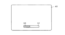
例えば、副画像が表示される3つの領域41,42,43は、同じ番組又は主画像としてのビデオ機器、例えばDVDプレーヤからのビデオデータから生成された画像が表示され、DVDのサブピクチャフォーマットでは、これらの領域41,42,43は、サブピクチャフォーマットの命令データのうちのカラー及びコントラスト変更命令に応じて生成される。これとは対照的に、図3において、ハイライトされた領域(以下、ハイライト領域という。)50は、利用者からの対話的な命令に応じて生成され、予めプログラムされた材料の一部ではない。例えば図1において、利用者がリモートコントローラ2のボタンスイッチを押すと、リモートコントローラ2は、その操作に対応した信号をメニュー発生器3に、例えば赤外線で送出する。メニュー発生器3は、ハイライト領域50及びメニュー表示領域51を表す副ビデオデータを発生して、メモリ12に記憶する。ハイライト領域50は、表示画面40に表示された背景とは異なるカラー及びコントラストを有する。
【0021】
図1に示すビデオ混合器14は、主ビデオデータと副ビデオデータを混合するための幾つかの技術のうちの1つを用いる。例えば、ビデオ混合器14は、表示画面40のカラー値及びコントラスト値と、副画像領域41のカラー値及びコントラスト値とを混合し、これによって、副画像が、表示画面40に表示された主画像上にスーパインポーズされ、主画像は、副画像領域41の副画像を透かして見ることができる。また、副ビデオプロセッサ20は、例えば副画像のビデオデータの処理において、カラー値及びコントラスト値を混合するのではなく、副画像領域41内の画素に対応した主画像のカラー値及びコントラスト値の代わりに、副画像領域41、第1の領域42、第2の領域43及びハイライト領域50のカラー値及びコントラスト値を用いるようにしている。なお、副ビデオプロセッサ20において何れのカラー値及びコントラスト値が選択されたとしても、選択されたカラー値及びコントラスト値は、ビデオ混合器14において主画像のカラー値及びコントラスト値と混合される。
【0022】
この実施例では、上述したように、副ビデオデータは、DVDのサブピクチャフォーマットで供給されるものとする。そして、副ビデオデータは、デジタルビデオプロセッサ10に入力され、CPU13の制御の下に、ヘッダ情報に応じて、デコーダ11でインタプリート、すなわち解釈され、メモリ12に記憶される。上述した実施例では、副画像領域41に表示される副画像のカラー値及びコントラスト値は、副画像領域41内のあらゆる走査線上の最大8点で変更することができる。命令データのうちのカラー及びコントラスト変更(以下、CHG_COLONという。)命令は、副画像領域41内のビデオデータを制御する命令である。CPU13は、記憶されているインストラクションに応じて動作し、サブピクチャフォーマットのフィールド及び走査線に対する命令データを効率良く、すなわち短い時間で簡単に処理する。なお、CPU13によって、画素データを実時間で効率的に処理することができないときは、画素データ及びそれに関連した命令データを、そのタスク専用のハードウェア、例えば副ビデオプロセッサ20によって処理するようにしている。副ビデオプロセッサ20内のハードウェア回路は、記憶されているインストラクションに応じて動作するのではなく、すなわち副ビデオプロセッサ20内のハードウェア回路は、CPU13から転送されてくる画素データ及びそれに関連した命令データを実行するように特別に設計されており、所望の副画像のビデオデータを生成するためのカラーデータ及びコントラストデータをビデオ混合器14に供給する。したがって、サブピクチャフォーマットの命令データのインタプリテション、すなわち実行は、CPU13の制御の下に、CPU13と専用の副ビデオプロセッサ20との間で分担される。ハードウェアで構成される副ビデオプロセッサ20は、画素データ及び比較的に複雑で負荷が大きなCHG_COLON命令を、CPU13よりも高速に処理する。また、副ビデオプロセッサ20は、データパスを選択できるように設計されており、副ビデオデータの他のフォーマット、例えばオンスクリーンディスプレイフォーマットや独自(proprietary)の副ビデオデータフォーマットを処理することができる。
【0023】
ビデオモニタ4は、その表示画面40に画像を表示するために、カラーデータ及び輝度データ、すなわちコントラストデータの連続したストリームを得るための周知の表示画像走査処理を実行する。ビデオモニタ4が、従来のアナログのモニタであるときは、表示される画像の走査処理は、ラスタスキャン処理であり、連続した水平走査線に対応した画素データを連続してD/A変換器16に供給することによって、例えば図2に示す画像が表示される。したがって、各画素データの位置は、直交座標系(Cartesian coordinate system)によって表すことができ、その直交座標系において、水平方向のx軸は、任意の1つの走査線上の画素データの位置によって定義され、その増加に従って目盛られ、垂直方向のy軸は、走査線番号で定義される水平の行によって目盛られる。したがって、副画像領域41の開始点44及び終了点45は、走査線上の位置及び走査線番号でそれぞれ定義されるx,y座標で表すことができる。また、開始点44及び終了点45は、副画像領域41を定義している。同様に、第1の領域42及び第2の領域43を表示するための走査線上のカラー及びコントラストの変更点は、画素番号、すなわちx座標で表すことができる。
【0024】
ここで、副ビデオプロセッサ20の具体的な構成について、図4を用いて説明する。
【0025】
ラスタスキャンの処理を開始する前に、CPU13は、メモリ12に記憶されている連続した走査線に対する命令データを順番に読み出す。命令データが簡単で複雑でない命令コードのときは、CPU13は、この命令データを、バスB1を介して副ビデオプロセッサ20のレジスタ21に転送する。例えば、CPU13は、処理されるブロックが副画像ブロック又は垂直帰線期間(vertical blanking interval:以下、VBIという。)ブロックに関係なく、用いられるモードがNTSCモード又はPALモードに関係なく、副ビデオデータのフォーマットがサブピクチャフォーマット、オンスクリーンディスプレイフォーマット又は独自のフォーマットに関係なく、フィールド及び走査線に対する命令データを、バスB1を介してレジスタ21の領域21aに転送する。また、CPU13は、副画像領域41の開始点44と終了点45を定義する垂直方向の走査線番号及び水平方向の画素番号を、バスB1を介して転送し、レジスタ21の領域21bに記憶する。同様にして、CPU13は、VBI領域及びHL(ハイライト)領域の開始点及び終了点の垂直方向の走査線番号及び水平方向の画素番号を、それぞれレジスタ21の領域21c,21dに転送する。
【0026】
命令データの調査において、CPU13は、CHG_COLON命令を検出すると、その命令データをメモリ12からバスB2を介して表示命令ファーストインファーストアウト(以下、FIFOという。)22に転送して記憶する。表示命令FIFO22は、2つのバッファからなり、2つのCHG_COLON命令を記憶する。表示命令解釈器23は、表示命令FIFO22から供給されるCHG_COLON命令をインタプリート、すなわち解釈して、命令データの要素を副ビデオプロセッサ20内の異なる場所に記憶する。具体的には、表示命令解釈器23は、カラー及びコントラストが次に変更される副画像領域41内の垂直方向の走査線番号をレジスタ21の領域21eに記憶する。また、表示命令解釈器23は、カラー及びコントラストを変更する走査線上の点を定義する画素番号をレジスタ21の領域21fに記憶する。書込アドレスコントローラ24は、カラーコードの命令データを、バスB5を介してカラーコードRAM25に転送して領域25aに記憶する。また、書込アドレスコントローラ24は、カラー及びコントラストのマップを示す命令データを、バスB5を介してカラー/コントラストRAM26に転送して領域26aに記憶する。
【0027】
また、ラスタスキャン処理が開始される前に、CPU13は、画素の要素のデータを、バスB2を介して画素FIFO27に転送して記憶する。また、CPU13は、画素データに関連する命令データを、バスB1を介して副ビデオプロセッサ20に転送する。このような命令データには、カラーコードをカラーコードRAM25に記憶する命令データ、カラー及びコントラストのマップをカラー/コントラストRAM26に記憶する命令データ、カラーパレットをカラーパレットRAM28に記憶する命令データが含まれる。具体的には、例えば、レジスタ21の領域21aに記憶されている制御データ(命令データ)が、テレビジョン受像機1がVBIモードであることを示しているときは、CPU13は、VBIカラーパレットコードをカラーパレットRAM28の領域28aに記憶する。このVBIモードにおけるカラーパレットコードは、グレースケールコードである。同様に、サブピクチャモードでは、CPU13は、副画像領域41の三原色データを示すカラーパレットを、バスB1を介してカラーパレットRAM28の領域28b,28c,28dに書き込む。なお、CPU13と、このテレビジョン受像機1のホストコンピュータ(図示せず)との間をバスB1で接続して、ホストコンピュータからカラーパレット情報をカラーパレットRAM28に書き込むようにしてもよい。また、CPU13が、VBIモード、サブピクチャモード又はハイライトモードに応じて、各モードに対応したカラー及びコントラストのマップデータをカラー/コントラストRAM26の領域26b,26c,26dに書き込むようにしてもよい。更に、CPU13が、VBIモード、サブピクチャモード又はハイライトモードに応じて、各モードに対応したカラーコードをカラーコードRAM25の領域25b,25c,25dに書き込むようにしてもよい。したがって、ラスタスキャンの処理が開始される前に、副ビデオプロセッサ20は、処理に必要なデータを記憶している。
【0028】
命令データの処理の一部として、CPU13は、ラスタスキャン処理を初期化する。その初期化において、CPU13は、1番目の走査線番号を、バスB1を介してレジスタ21の領域21gに記憶する。次に、走査線上の連続した水平方向の画素番号に関連した画素データが、メモリ12からバスB3を介してビデオ混合器14に転送される。この画素データの転送は、バスB6を介して供給される水平同期信号によって開始される。具体的には、画素カウンタ29は、水平同期信号によって初期化され、順次増加するクロック信号を生成し、このクロック信号を信号線L3を介してメモリ12に供給して、メモリ12からの画素データの転送を制御する。例えば、画素カウンタ29は、走査線上の画素の数に等しい多くの固有の状態、すなわちカウント値を有する。領域検出器30は、画素カウンタ29のカウント値に基づいて、画素カウンタ29が示す現在の画素の座標を求め、レジスタ21の領域21gに記憶されている走査線番号が領域21b〜21eに記憶されている走査線番号の座標と一致するのを検出する。なお、副ビデオプロセッサ20が動作していないときは、主ビデオデータは、メモリ12からバスB3を介してビデオ混合器14に転送され、そこで、変更されることなく、信号線L1を介してエンコーダ15に供給される。
【0029】
ラスタスキャン処理は、レジスタ21の領域21gで示される現在の走査線番号における画素カウンタ29の状態が、レジスタ21の領域21bに記憶されている副画像領域41の開始点44又は領域21dに記憶されているHL(ハイライト)領域50の走査線番号及び画素番号に一致したことを領域検出器30が検出するまで、画素及び走査線毎に行われる。領域検出器30は、カラー及びコントラストを変更する領域の開始点を表す現在の画素を検出すると、現在の画素に混合処理を適用させるフラグを信号線L6を介してビデオ混合器14に供給する。
【0030】
副画像領域41が検出されると、副画像のビデオデータは、副ビデオプロセッサ20によって、CPU13からそこに予め読み込まれた命令データと、CPU13から現在の画素のカウント値により同時に読み込まれた命令データとを用いて、処理される。サブピクチャフォーマットで圧縮された副画像の画素情報は、画素FIFO27からランレングスデコーダ31に供給され、そこで伸長されて、読出アドレスコントローラ32に供給される。読出アドレスコントローラ32は、画素データを解釈し、カラーコードRAM25の領域25cから信号線L2を介して所望のカラーコードを読み込む。そして、読出アドレスコントローラ32は、このカラーコードを用い、信号線L4を介してカラーパレットRAM28を制御し、カラーパレットRAM28の領域28b〜28dに記憶されているカラーパレットから適切なカラーデータを選択する。そして、カラーパレットRAM28は、この適切なカラーデータをバスB7を介してビデオ混合器14に供給する。また、読出アドレスコントローラ32は、信号線L5を介してカラー/コントラストRAM26を制御し、カラー/コントラストRAM26は、領域26cに予め読み込んでいるコントラストデータを、バスB8を介してビデオ混合器14に供給する。
【0031】
ビデオ混合器14は、副画像領域41内の現在の画素のカラーデータ及びコントラストデータを、主画像のカラーデータ及びコントラストデータと混合、すなわち副画像を主画像にスーパインポーズする。そして、バスB6を介して次の水平同期信号が画素カウンタ29に供給されると、それによって次の画素データに対する処理が開始される。上述した処理と同様の処理によって、領域検出器30は、副画像領域41内の次の画素を検出し、読出アドレスコントローラ32は、バスB7,B8を介して適切なカラーデータ及びコントラストデータがビデオ混合器14に供給されるように、カラーパレットRAM28及びカラー/コントラストRAM26を制御する。現在の走査線上の各画素に対する処理が順次返される。画素FIFO27は、そこに記憶している画素の半分に対して処理が行われると、信号線L7を介してCPU13に割込をかけ、それにより、CPU13は、バスB2を介して新たな画素データを画素FIFO27に転送する。
【0032】
現在の画素番号を処理する際に、領域検出器30は、現在の走査線番号が、他の領域42又は領域43に一致すること、すなわちレジスタ21の領域21eに記憶されている走査線番号の1つに一致したことを検出する。また、領域検出器30は、現在の画素が、他の領域42又は領域43の開始値であること、すなわちレジスタ21の領域21c,21fに記憶されている画素の1つに一致したことを検出する。具体的には、領域検出器30は、現在の画素が、点#1として記憶されている第1の領域42の開始点に一致したことを検出する。このとき、新たな命令データをカラーパレットRAM28の領域28b,28c,28dに記憶する。そして、読出アドレスコントローラ32は、カラーコードRAM25の領域25cの副画像のカラーコードを用いる代わりに、ランレングスデコーダ31からのデコードされた画素データを用いて、カラーコードRAM25の領域25aから点#1のカラーコードを読み出す。カラーコードRAM25の領域25aのカラーコードは、副画像領域41に関連したCHG_COLON命令の表示命令解釈器23による処理によって、予め記憶されたものである。そして、読出アドレスコントローラ32は、カラーパレットRAM28の領域28b,28c,28dに新たに記憶されたカラーパレットから適切なカラーデータを読み出し、バスB7を介して出力する。一方、書込アドレスコントローラ24は、カラー及びコントラストのマップをカラー/コントラストRAM26の領域26aに前もって記憶させており、読出アドレスコントローラ32は、領域26cの副画像のデータの代わりに、領域26aから点#1に対するカラー及びコントラストのマップを読み出し、バスB8を介して出力する。
【0033】
領域検出器30が現在処理中の画素(以下アクティブ画素ともいう。)がレジスタ21の領域21fに記憶されている点#2として定義された第2の領域43の開始点に一致することを検出するまで、点#1に関連したカラーコード及びコントラストデータが、その走査線上の連続した各画素に対して用いられる。その後、読出アドレスコントローラ32は、ランレングスデコーダ31からの画素データを用いて、カラーコードRAM25の領域25aから第2の領域43の点#2の所望のカラーコードを読み出し、そのカラーコードを解釈して、カラーパレットRAM28の領域28b,28c,28dから所望のカラーデータを選択する。また、同様に、読出アドレスコントローラ32は、カラー/コントラストRAM26の領域26aから点#2に対する所望のコントラストデータを選択する。これらのカラーデータ及びコントラストデータは、アクティブ画素が、点#3で定義される第2の領域43の終了点、すなわちカラーコード及びコントラストデータを第1の領域42のカラーコード及びコントラストデータに戻す点に一致するまで、用いられる。第1の領域42のカラーコード及びコントラストデータは、アクティブ画素が、点#4で定義される第1の領域42の終了点、すなわちカラーコード及びコントラストデータを副画像領域41のカラーコード及びコントラストデータに戻す点に一致するまで、用いられる。副画像領域41のカラーコード及びコントラストデータは、副画像領域41の終了点まで用いられる。その後、副ビデオプロセッサ20は、信号線L6及びバスB7,B8を介するデータの出力を停止し、この結果、表示画面40上の主画像のカラーコード及びコントラストデータが、混合されずに用いられる。主画像のカラーコード及びコントラストデータは、現在ラスタスキャンされている走査線が終了するまで用いられる。以上の処理が、表示画面40の各走査線に対して繰り返される。
【0034】
表示画面40の1つのフィールドに対する1つのCHG_COLON命令が実行された後、次のCHG_COLON命令が表示命令FIFO22から読み出されて、表示命令解釈器23に供給される。表示命令解釈器23は、この新たなCHG_COLON命令を解釈して、副画像を有する新たなフィールドを表示するために、新たな副画像の各データをレジスタ21の領域21b,21e,21fに記憶する。また、書込アドレスコントローラ24は、新たなカラーコードをカラーコードRAM25の領域25aに記憶するとともに、新たなカラー及びコントラストのマップをカラー/コントラストRAM26の領域26aに記憶する。更に、新たなCHG_COLON命令の処理を行うことによって表示命令FIFO22の片方のバッファが空になると、表示命令FIFO22は、信号線L9を介して、CPU13に割込をかける。そして、CPU13は、メモリ12からバスB3を介して、CHG_COLON命令用の新たな命令データを表示命令FIFO22に転送する。
【0035】
CPU13は、メモリ12に記憶されている命令データを順番に調べ、図3に示すハイライト領域50に対する命令データを検出すると、新たなカラーコードをカラーコードRAM25の領域25dに記憶し、新たなカラーパレットをカラーパレットRAM28の領域28b,28c,28dに記憶し、新たなカラー及びコントラストのマップをカラー/コントラストRAM26の領域26dに記憶する。領域検出器30が、アクティブ画素がハイライト領域50内にあることを検出すると、読出アドレスコントローラ32は、アクティブ画素のデータを用いて、カラーコードRAM25の領域25dから所望のハイライトのカラーコードを読み出し、このハイライトのカラーコードを用いて、カラーパレットRAM28の領域28b,28c,28dから適切なカラーデータを選択する。また、読出アドレスコントローラ32は、カラー/コントラストRAM26の領域26dからハイライト用のコントラストデータを読み出す。
【0036】
かくして、この本発明を適用したテレビジョン受像機1では、DVD規格に準拠したサブピクチャフォーマットのビデオデータを上述のように処理することによって、表示画面40に表示された主画像の上に、例えば図2に示す副画像領域41、第1の領域42、第2の領域43の副画像や、図3に示すハイライト領域50の画像をスーパインポーズすることができる。また、このテレビジョン受像機1では、サブピクチャフォーマットに準拠した副画像の情報の処理において、異なる表示を行わせる命令データを2つの異なる回路で分割して処理するようにしている。具体的には、単純で時間的に厳しくないフィールド及び走査線の命令データは、プログラムされたインストラクションで動作するCPU13で実行及び処理し、バスB1を介してレジスタ21に転送する。一方、CHG_COLON命令に関係する複雑な副ビデオデータの画素データは、CPU13で検出して、メモリ12から表示命令FIFO22に転送し、プログラムで動作しないハードウェア、すなわち表示命令解釈器23、書込アドレスコントローラ24、カラーコードRAM25で処理する。これらのハードウェアは、プログラムされたインストラクションで動作するものではなく、CHG_COLON命令をCPU13で処理するよりも高速に処理するように専用に設計されている。
【0037】
ここで、サブピクチャフォーマットの副ビデオデータの処理を、図5及び図6に示すフローチャートを用いて説明する。
【0038】
ステップS1において、CPU13は、入力端子5を介して供給される副ビデオデータをメモリ12に記憶する。
【0039】
ステップS2において、CPU13は、副ビデオデータがサブピクチャフォーマットかを判定し、該当する(Yes)ときはステップS3に進み、該当しない(No)ときはステップS5に進む。
【0040】
ステップS3おいて、CPU13は、簡単で複雑でない命令コードからなる第1の命令データを処理する。
【0041】
ステップS4において、CPU13は、より複雑な命令コード、例えばCHG_COLON命令の命令コードからなる第2の命令データと、画素データとを副ビデオプロセッサ20に転送する。
【0042】
ここで、ステップS4における副ビデオプロセッサ20の具体的な処理を、図6に示すフローチャートを用いて説明する。
【0043】
ステップS11において、副ビデオプロセッサ20の領域検出器30は、アクティブ画素が副画像領域内にあるかを判定し、該当するときはステップS12に進み、該当しないときは終了する。
【0044】
ステップS12において、領域検出器30は、アクティブ画素が点#1〜#8の何れか1つに一致するかを判定し、該当するときはステップS13に進み、該当しないときはステップS14に進む。
【0045】
ステップS13において、読出アドレスコントローラ32は、カラーパレットRAM28から適切なカラーデータを出力させるためのカラーコードを、カラーコードRAM25の領域25aから選択する。また、読出アドレスコントローラ32は、カラー/コントラストRAM26の領域26aから適切なコントラストデータを選択する。
【0046】
ステップS14において、領域検出器30は、アクティブ画素がハイライト領域内かを判定し、該当するときはステップS15に進み、該当しないときは16ステップSに進む。
【0047】
ステップS15において、読出アドレスコントローラ32は、カラーコードRAM25、カラーパレットRAM28からそれぞれ適切なカラーコード、カラーデータを選択し、カラー/コントラストRAM26の領域26dからコントラストデータを選択する。
【0048】
ステップS16において、読出アドレスコントローラ32は、アクティブ画素がVBI領域にあるかを判定し、該当するときはステップS17に進み、該当しないときはステップS18に進む。
【0049】
ステップS17において、読出アドレスコントローラ32は、カラーコードRAM25、カラーパレットRAM28及びカラー/コントラストRAM26から、適切なカラーコード、カラーデータ及びコントラストデータを選択する。
【0050】
ステップS18において、すなわちアクティブ画素が、副画像の領域にあるが、他の領域にないとき、読出アドレスコントローラ32は、カラーコードRAM25、カラーパレットRAM28及びカラー/コントラストRAM26から、適切なカラーコード、カラーデータ及びコントラストデータを選択する。
【0051】
ここで、領域検出器30は、画素データが圧縮されていないオンスクリーンディスプレイフォーマットの副ビデオデータの処理することができる。
【0052】
図5のステップS5において、CPU13は、副ビデオデータがオンスクリーンディスプレイフォーマットかを判定し、該当するときはステップS6に進み、該当しないときはステップS7に進む。
【0053】
ステップS6において、CPU13は、オンスクリーンディスプレイフォーマットの画素データを副ビデオプロセッサ20に転送する。なお、副ビデオデータがオンスクリーンディスプレイフォーマットのときは、ランレングスデコーダ31は不要であり、読出アドレスコントローラ32は、圧縮されていない画素データを、画素FIFO27から直接読み出す。そして、読出アドレスコントローラ32は、カラーコードRAM25から所望のカラーコードを読み出して、カラーパレットRAM28から所望のカラーデータを選択する。
【0054】
ステップS7において、CPU13は、副ビデオデータが独自のフォーマットかを判定し、該当するときはステップS8に進み、該当しないときはステップS9に進む。
【0055】
ステップS8において、CPU13は、独自のフォーマットの画素データを副ビデオプロセッサ20に転送する。
【0056】
ステップS9において、CPU13は、副ビデオデータが、表示装置で用いられているアナログ信号に直接変換することができる生の画素データであるかを判定し、該当するときはステップS10に進み、該当しないときは終了する。
【0057】
ステップS10において、CPU13は、供給される生の画素データを副ビデオプロセッサ20に供給し、副ビデオプロセッサ20は、その画素データをそのままビデオ混合器14に供給する。このとき、CPU13は、読出アドレスコントローラ32が生の画素データをバスB7に接続された信号線L8を介して出力するように制御し、これによって、生の画素データがビデオ混合器14に供給される。以上の説明でも明らかなように、CPU13が副ビデオデータの処理を行う際に、副ビデオプロセッサ20は、その内部状態又は条件が一旦設定されて、副ビデオデータの処理を一旦開始すると、その条件が更新されるまでは、その処理を続行する。また、副ビデオプロセッサ20は、上述したように、様々なフォーマットの副ビデオデータを処理することができる。更に、副ビデオプロセッサ20は、上述したように内部のデータパスを柔軟に変えることができ、新たなフォーマットの副ビデオデータも処理することができる。
【0058】
【発明の効果】
本発明に係るデジタルビデオ処理装置は、異なる2つのデータフォーマットで供給され、主画像上にスーパインポーズされる副ビデオデータを、画像表示のための走査処理期間中に処理するデジタルビデオ処理装置において、第1のフォーマットの第1の副ビデオデータ及び第2のフォーマットの第2の副ビデオデータを記憶するメモリと、メモリに接続され、第1及び第2の副ビデオデータの第1の部分を処理するとともに、第1の副ビデオデータが第1のデータフォーマットであるか、第2の副ビデオデータが第2のデータフォーマットであるかを検出する中央処理装置と、メモリに接続され、中央処理装置に応答して、第1のデータフォーマットの第1の副ビデオデータ及び第2のデータフォーマットの第2の副ビデオデータの画素データを、画像表示のための走査処理期間中に処理して、カラーコードを生成する副ビデオプロセッサとを備える。そして、このデジタルビデオ処理装置では、画像表示のための走査処理期間中に、カラーコードが副ビデオプロセッサによって生成される。また、命令データの実行は、プログラムで動作する中央処理装置と、専用のハードウェアからなる副ビデオプロセッサで分担して行われる。具体的には、中央処理装置は、簡単で時間的に厳しくない画素データに関係しない処理を行い、専用のハードウェアからなる副ビデオプロセッサは、中央処理装置の制御の下で動作し、より複雑な、時間的に厳しい画素データの処理を実時間で行う。このように、ビデオデータの処理を分割して行うことにより、画素データを必要な速度で処理することができるとともに、中央処理装置は、他のタスクを実行することができる。
【図面の簡単な説明】
【図1】 本発明を適用したテレビジョン受像機の要部の具体的な構成を示すブロック図である。
【図2】 ビデオモニタの表示画面の具体的な表示例を示す図である。
【図3】 ビデオモニタの表示画面の具体的な表示例を示す図である。
【図4】 副ビデオプロセッサの具体的な構成を示すブロック図である。
【図5】 副ビデオデータの処理を説明するためのフローチャートである。
【図6】 副ビデオデータの処理を説明するためのフローチャートである。
【符号の説明】
1 テレビジョン受像機、2 リモートコントローラ、3 メニュー発生器、4ビデオモニタ、10 デジタルビデオプロセッサ、11 デコーダ、12メモリ、13 CPU、14 ビデオ混合器、15 エンコーダ、16 D/A変換[0001]
BACKGROUND OF THE INVENTION
The present invention relates to a digital video processing apparatus and a sub video data processing method. For example, the present invention relates to digital processing of a video signal for displaying an image on a screen of a television receiver, in particular, superimposing an image based on sub-video data on an image based on a main video signal. Related to technology.
[0002]
[Prior art]
In the screen display of a television receiver, it is often necessary to superimpose the other image on one image. Conventionally, the video signal of the image superposed in this way is generally generated as part of the video signal of the source program. By the way, it may be necessary to be able to generate a video signal of a superimpose image not only from a video signal of a source program but also by interactive input of a user. Most television receivers manufactured today are video signals of material from various source devices such as video tape recorders (hereinafter referred to as VTRs), digital video discs (hereinafter referred to as DVDs) players, cable broadcasting. And an interface through which video signals from digital satellite broadcasting (hereinafter referred to as DSS) are input. Some of these source devices output digital audio signals and video signals compliant with the Moving Picture Experts Group (hereinafter referred to as MPEG) -2 audio / video compression standard. Therefore, a modern television receiver is required to have a function of processing a digital input signal and generating a digital signal for displaying a desired image. In many cases, these digital signals are converted to analog signals for display on an analog monitor receiver.
[0003]
Also, most television receivers manufactured today and / or (plug compatible) source devices that can be plugged into them superimpose a menu of operations and settings on the display image of the program. Thus, the user has a function to execute them interactively. Then, the user can select, for example, the display of captions or subtitles using the superimposed menu display. Another use of the superimpose is to display a menu for the user to adjust or set according to his / her preference, for example, a setting menu for audio and video levels, game time, difficulty level, and the like. Some of these setting menus are displayed as scale bars of a linear scale that changes according to the user's button operation.
[0004]
The source device of the program outputs digital information as a data packet. For example, audio data and main video data are supplied as data packets conforming to the MPEG-2 format. On the other hand, information about sub-video data, that is, an image to be superimposed, is supplied as data packets in several formats. For example, superimposed image information is supplied in a sub-picture format defined by the so-called DVD standard. The sub-picture format includes a header block, a pixel data block, and an instruction data block. In general, the header is used to identify the general nature of the data. For example, the header is used to identify a data format such as whether pixel data is compressed, an instruction structure is used, and how data is read. In the sub-picture format, pixel data includes color information and contrast information, and is compressed by a predetermined compression technique, for example, run-length encoding. The instruction data in the sub-picture format is used to identify the position and size of a highlighted area (hereinafter referred to as a highlight area) in the sub-image, and is used to identify one or more small highlights in the sub-picture format. The light area has a unique color value, contrast value, and the like.
[0005]
In another application of superimpose, the sub video data to be superposed has a format different from the data format of the main video data. For example, in the on-screen display format in the DVB / STB format, the sub video data generally includes only one header block and an uncompressed pixel data block. Further, although not visible to the viewer, the sub video data is also used in a vertical blanking interval (hereinafter referred to as VBI) between individual complete image fields or frames. Also, in other applications, the sub-video data is a raw pixel data that can be directly converted into an original format such as a DSS format used in digital satellite broadcasting or an analog signal used in a display device. Also supplied.
[0006]
Traditionally, television receivers designed to be compatible with a single format, such as television receivers having an on-screen display format of superimposed video information, have been sold commercially. However, television receivers developed in recent years and compliant with the digital sub-picture format defined by the DVD standard require a function for recognizing and processing the respective formats of video data to be superimposed.
[0007]
[Problems to be solved by the invention]
The present invention has been made in view of the above circumstances, and an object of the present invention is to improve the architecture of a digital video processing apparatus for processing video data of a sub-image superimposed on a main image. That is. In the digital video processing apparatus of this improved architecture, the processing of the sub video data is shared between a central processing unit (hereinafter referred to as CPU) and dedicated hardware controlled by the CPU. This architecture allows video data to be processed at high speed in real time without placing an unnecessary load on the CPU in dedicated hardware, that is, in a state where the CPU can execute other tasks. It is flexible so that it can handle the processing of sub-video data supplied in the data format.
[0008]
[Means for Solving the Problems]
A digital video processing apparatus according to the present invention is a digital video processing apparatus that processes sub-video data supplied in two different data formats and superimposed on a main image during a scan processing period for image display. A memory for storing the first sub-video data in the first format and the second sub-video data in the second format; and a first portion of the first and second sub-video data connected to the memory A central processing unit for processing and detecting whether the first sub-video data is in the first data format or whether the second sub-video data is in the second data format; In response to the device, the pixel data of the first sub-video data in the first data format and the second sub-video data in the second data format. The data were processed during the scanning process period for image display, and a sub-video processor for generating a color code.
[0009]
Also, the digital video processing apparatus according to the present invention is a digital video processing apparatus that processes sub-video data that includes pixel data and command data and is superimposed on a main image during a scanning processing period for image display. In Vice A memory for storing pixel data of video data and command data; a central processing unit connected to the memory for processing a first portion of the command data of sub-video data; and connected to the memory in response to the central processing unit A secondary video processor for processing the second portion of the instruction data of the secondary video data and the pixel data during a scanning process for image display; The sub-video processor has a first memory for storing pixel data, a second memory for storing command data defining a first area of the sub-image to be superimposed on the main image, and a second image of the sub-image. A detector that detects the appearance of an active pixel in the main image within one area, and the active pixel of the main image in the pixel data stored in the first memory based on the detection result of the detector. A sub-video color controller that generates a color code for pixel data; The central processing unit and the secondary video processor Secondary video data Color code and contrast data are selectively controlled based on the command data.
[0010]
Therefore, in these digital video processing apparatuses, the color code is generated by the secondary video processor during the scanning process for image display. In addition, execution of instruction data is performed in a shared manner by a central processing unit that operates according to a program and a sub video processor that includes dedicated hardware. Specifically, the central processing unit performs processing that is not related to pixel data that is simple and not strict in time, and the secondary video processor composed of dedicated hardware operates under the control of the central processing unit and is more complicated. In addition, time-critical pixel data processing is performed in real time. Thus, by dividing the processing of the video data, the pixel data can be processed at a necessary speed, and the central processing unit can execute other tasks.
[0011]
The sub-video data processing method according to the present invention is a sub-video data processing method for processing sub-video data superimposed on a main image during a scanning process period for displaying an image. And reading the second sub-video data by the central processing unit, processing the first part of the first and second sub-video data by the central processing unit, and the first sub-video data being the first Detecting whether the data format or the second sub-video data is the second data format, and storing the first and second pixel data relating to the first and second sub-video data in the memory Transferring the first and second pixel data to the secondary video processor in response to the central processing unit; and transferring the first and second pixel data to the secondary video processor; The O processor, and a step of processing based on each of the first and second data format, to generate first and second color code of the first and second sub-video data, respectively.
[0012]
The sub-video data processing method according to the present invention is a sub-video data processing method for processing sub-video data superimposed on a main image during a scanning process period for displaying an image. A step of reading the sub video data by the central processing unit, a step of detecting that the first sub video data is the first of the two sub video data formats, and the first sub video data Storing the first pixel data in the memory; transferring the first pixel data to the secondary video processor; and processing the first pixel data by the secondary video processor based on the first data format. Generating first color data and contrast data.
[0013]
Also, the sub-video data processing method according to the present invention supplies sub-video data supplied in a format including at least pixel data and command data and superposed on the main image during a scanning process period for image display. Storing the pixel data and command data defining a first region of the sub image to be superimposed on the main image in a memory; and a first command data Processing in a central processing unit and a second portion of pixel data and instruction data in a secondary video processor in response to a central processing unit processing the first part of the instruction data and scanning Generating color data and contrast data represented by pixel data during the processing period. The step of generating the color data and the contrast data is a step of selecting an active pixel of the main image and whether the active pixel is in the first region of the sub image during the scanning process in the sub video processor. And generating color information about the pixels used with the active pixels of the main image in the first region of the sub-image. To do.
[0014]
DETAILED DESCRIPTION OF THE INVENTION
A digital video processing apparatus and sub video data processing method according to the present invention will be described below with reference to the drawings. FIG. 1 is a block diagram showing a configuration of a main part of a television receiver to which the present invention is applied.
[0015]
As shown in FIG. 1, the
[0016]
The
[0017]
Specifically, as shown in FIG. 1, the
[0018]
The
[0019]
Here, a specific display example of the display screen of the
[0020]
For example, in the three
[0021]
The
[0022]
In this embodiment, as described above, the sub video data is supplied in the DVD sub picture format. Then, the sub video data is input to the
[0023]
In order to display an image on the
[0024]
Here, a specific configuration of the
[0025]
Before starting the raster scan process, the
[0026]
In examining the instruction data, when detecting the CHG_COLON instruction, the
[0027]
Further, before the raster scan processing is started, the
[0028]
As part of the instruction data processing, the
[0029]
In the raster scan process, the state of the
[0030]
When the
[0031]
The
[0032]
When processing the current pixel number, the
[0033]
The
[0034]
After one CHG_COLON instruction for one field of the
[0035]
When the
[0036]
Thus, in the
[0037]
Here, processing of sub-video data in the sub-picture format will be described using the flowcharts shown in FIGS.
[0038]
In step S <b> 1, the
[0039]
In step S2, the
[0040]
In step S3, the
[0041]
In step S <b> 4, the
[0042]
Here, specific processing of the
[0043]
In step S11, the
[0044]
In step S12, the
[0045]
In step S <b> 13, the
[0046]
In step S14, the
[0047]
In step S15, the
[0048]
In step S16, the
[0049]
In step S <b> 17, the
[0050]
In step S18, that is, when the active pixel is in the sub-image area but not in the other area, the
[0051]
Here, the
[0052]
In step S5 of FIG. 5, the
[0053]
In step S <b> 6, the
[0054]
In step S7, the
[0055]
In step S <b> 8, the
[0056]
In step S9, the
[0057]
In step S <b> 10, the
[0058]
【The invention's effect】
A digital video processing apparatus according to the present invention is a digital video processing apparatus that processes sub-video data supplied in two different data formats and superimposed on a main image during a scan processing period for image display. A memory for storing the first sub-video data in the first format and the second sub-video data in the second format; and a first portion of the first and second sub-video data connected to the memory A central processing unit for processing and detecting whether the first sub-video data is in the first data format or whether the second sub-video data is in the second data format; In response to the device, the pixel data of the first sub-video data in the first data format and the second sub-video data in the second data format. The data were processed during the scanning process period for image display, and a sub-video processor for generating a color code. In this digital video processing apparatus, the color code is generated by the sub video processor during the scanning processing period for image display. In addition, execution of instruction data is performed in a shared manner by a central processing unit that operates according to a program and a sub video processor that includes dedicated hardware. Specifically, the central processing unit performs processing that is not related to pixel data that is simple and not strict in time, and the secondary video processor composed of dedicated hardware operates under the control of the central processing unit and is more complicated. In addition, time-critical pixel data processing is performed in real time. Thus, by dividing the processing of the video data, the pixel data can be processed at a necessary speed, and the central processing unit can execute other tasks.
[Brief description of the drawings]
FIG. 1 is a block diagram illustrating a specific configuration of a main part of a television receiver to which the present invention is applied.
FIG. 2 is a diagram illustrating a specific display example of a display screen of a video monitor.
FIG. 3 is a diagram illustrating a specific display example of a display screen of a video monitor.
FIG. 4 is a block diagram showing a specific configuration of a sub video processor.
FIG. 5 is a flowchart for explaining processing of sub-video data.
FIG. 6 is a flowchart for explaining processing of sub-video data.
[Explanation of symbols]
1 TV receiver, 2 remote controller, 3 menu generator, 4 video monitor, 10 digital video processor, 11 decoder, 12 memory, 13 CPU, 14 video mixer, 15 encoder, 16 D / A conversion
Claims (12)
第1のフォーマットの第1の副ビデオデータ及び第2のフォーマットの第2の副ビデオデータを記憶するメモリと、
上記メモリに接続され、上記第1及び第2の副ビデオデータの第1の部分を処理するとともに、該第1の副ビデオデータが上記第1のデータフォーマットであるか、該第2の副ビデオデータが上記第2のデータフォーマットであるかを検出する中央処理装置と、
上記メモリに接続され、上記中央処理装置に応答して、上記第1のデータフォーマットの第1の副ビデオデータ及び上記第2のデータフォーマットの第2の副ビデオデータの画素データを、上記画像表示のための走査処理期間中に処理して、カラーコードを生成する副ビデオプロセッサとを備えるデジタルビデオ処理装置。In a digital video processing apparatus that processes secondary video data supplied in two different data formats and superimposed on a main image during a scanning process for image display.
A memory for storing first sub-video data in a first format and second sub-video data in a second format;
Connected to the memory and processing a first portion of the first and second sub-video data and whether the first sub-video data is in the first data format or the second sub-video A central processing unit for detecting whether the data is in the second data format;
In response to the central processing unit connected to the memory, the pixel data of the first sub video data of the first data format and the second sub video data of the second data format are displayed on the image display. A digital video processing apparatus comprising: a secondary video processor for processing during a scanning processing period for generating a color code.
上記副ビデオデータの画素データ及び命令データを記憶するメモリと、
上記メモリに接続され、上記副ビデオデータの命令データの第1の部分を処理する中央処理装置と、
上記メモリに接続され、上記中央処理装置に応答して、上記副ビデオデータの命令データの第2の部分及び画素データを、上記画像表示のための走査処理期間中に処理する副ビデオプロセッサとを備え、
上記副ビデオプロセッサは、
上記画素データを記憶する第1のメモリと、
上記主画像上にスーパインポーズされる副画像の第1の領域を定義する命令データを記憶する第2のメモリと、
上記副画像の第1の領域内で上記主画像のアクティブ画素の出現を検出する検出器と、
上記検出器の検出結果に基づいて、上記第1のメモリに記憶されている画素データのうちの上記主画像のアクティブ画素と共に用いられる画素データに関するカラーコードを生成させる副ビデオカラーコントローラとを備え、
上記中央処理装置及び副ビデオプロセッサは、上記副ビデオデータの命令データに基づいて、カラーコード及びコントラストデータを選択的に制御することを特徴とするデジタルビデオ処理装置。In a digital video processing apparatus that processes sub-video data that includes pixel data and command data and is superimposed on a main image during a scanning process for image display.
A memory for storing pixel data and command data of the sub- video data;
A central processing unit connected to the memory and processing a first portion of the instruction data of the sub-video data;
A sub-video processor connected to the memory and processing a second portion of the instruction data of the sub-video data and pixel data in response to the central processing unit during a scan processing period for the image display; Prepared,
The secondary video processor is
A first memory for storing the pixel data;
A second memory for storing command data defining a first region of the sub-image to be superimposed on the main image;
A detector for detecting the appearance of active pixels of the main image within a first region of the sub-image;
A sub-video color controller that generates a color code related to pixel data used together with active pixels of the main image among the pixel data stored in the first memory based on a detection result of the detector;
The digital video processing apparatus, wherein the central processing unit and the secondary video processor selectively control color code and contrast data based on the instruction data of the secondary video data .
上記副ビデオプロセッサは、上記副画像の第2の領域に関する命令データを処理して、カラーコードを上記副ビデオカラーコントローラに供給する命令データコントローラを更に備え、
上記副ビデオカラーコントローラは、上記副画像の第2の領域内の上記主画像のアクティブ画素と共に用いられる画素に関するカラーコードを上記命令データコントローラで生成させることを特徴とする請求項2に記載のデジタルビデオ処理装置。The detector detects the occurrence of an active pixel of the main image in the second region of said sub-image of the first region of the sub-image,
The sub video processor further includes a command data controller that processes command data related to the second region of the sub image and supplies a color code to the sub video color controller.
The sub video color controller, digital claim 2, characterized in that to produce a color code for a pixel for use with the active pixels of the main image in a second region of the sub image by the instruction data controller Video processing device.
第1及び第2の副ビデオデータを中央処理装置によって読み込むステップと、
上記第1及び第2の副ビデオデータの第1の部分を上記中央処理装置によって処理するステップと、
上記第1の副ビデオデータが第1のデータフォーマットであるか、上記第2の副ビデオデータが第2のデータフォーマットであるかを検出するステップと、
上記第1及び第2の副ビデオデータに関する第1及び第2の画素データをメモリに記憶するステップと、
上記第1及び第2の画素データを、上記中央処理装置に応答して副ビデオプロセッサに転送するステップと、
上記第1及び第2の画素データを、上記副ビデオプロセッサにより、上記第1及び第2のデータフォーマットのそれぞれに基づいて処理して、上記第1及び第2の副ビデオデータの第1及び第2のカラーコードをそれぞれ生成するステップとを有する副ビデオデータの処理方法。In a processing method of sub-video data, the sub-video data superposed on the main image is processed during a scanning process period for displaying an image.
Reading the first and second sub-video data by the central processing unit;
Processing the first portion of the first and second sub-video data by the central processing unit;
Detecting whether the first sub-video data is in a first data format or whether the second sub-video data is in a second data format;
Storing first and second pixel data relating to the first and second sub-video data in a memory;
Transferring the first and second pixel data to a secondary video processor in response to the central processing unit;
The first and second pixel data are processed by the sub video processor based on the first and second data formats, respectively, and the first and second sub video data are first and second processed. A method of processing sub-video data, comprising: generating each of the two color codes.
第1の副ビデオデータを中央処理装置によって読み込むステップと、
上記第1の副ビデオデータが、2つの副ビデオデータフォーマットのうちの第1のフォーマットであることを検出するステップと、
上記第1の副ビデオデータに関する第1の画素データをメモリに記憶するステップと、
上記第1の画素データを副ビデオプロセッサに転送するステップと、
上記第1の画素データを、上記副ビデオプロセッサにより、上記第1のデータフォーマットに基づいて処理して、第1のカラーデータ及びコントラストデータを生成するステップとを有する副ビデオデータの処理方法。In a processing method of sub-video data, the sub-video data superposed on the main image is processed during a scanning process period for displaying an image.
Reading the first sub-video data by the central processing unit;
Detecting that the first sub-video data is a first of two sub-video data formats;
Storing first pixel data relating to the first sub-video data in a memory;
Transferring the first pixel data to a secondary video processor;
And processing the first pixel data by the sub video processor based on the first data format to generate first color data and contrast data.
上記第2の副ビデオデータが、上記2つの副ビデオデータフォーマットのうちの第2のフォーマットであることを検出するステップと、
上記第2の副ビデオデータに関する第2の画素データを上記メモリに記憶するステップと、
上記第2の画素データを、上記第2のデータフォーマットの第1の部分を処理する上記中央処理装置に応答して、副ビデオプロセッサに転送するステップと、
上記第2の画素データを、上記副ビデオプロセッサにより、上記第2のデータフォーマットに基づいて処理して、第2のカラーデータ及びコントラストデータを生成するステップとを有する請求項6に記載の副ビデオデータの処理方法。And reading the second sub-video data by the central processing unit;
Detecting that the second sub-video data is a second one of the two sub-video data formats;
Storing second pixel data relating to the second sub-video data in the memory;
Transferring the second pixel data to a secondary video processor in response to the central processing unit processing a first portion of the second data format;
The sub-video according to claim 6 , further comprising: processing the second pixel data by the sub-video processor based on the second data format to generate second color data and contrast data. How to process the data.
上記画素データと、主画像上にスーパインポーズされる副画像の第1の領域を定義する上記命令データとをメモリに記憶するステップと、
上記命令データの第1の部分を中央処理装置において処理するステップと、
上記画素データ及び上記命令データの第2の部分を、副ビデオプロセッサにおいて、上記命令データの第1の部分を処理する中央処理装置に応答して処理し、上記走査処理期間中に、該画素データで表されるカラーデータ及びコントラストデータを生成するステップとを有し、
上記カラーデータ及びコントラストデータを生成するステップは、
上記副ビデオプロセッサにおいて、上記走査処理期間中に、上記主画像のアクティブ画素を選択するステップと、
上記アクティブ画素が上記副画像の第1の領域内かを識別するステップと、
上記副画像の第1の領域内の上記主画像のアクティブ画素と共に用いられる画素に関するカラー情報を生成するステップとを有する副ビデオデータの処理方法。In a method of processing sub-video data, wherein sub-video data supplied in a format including at least pixel data and command data and superposed on a main image is processed during a scan processing period for image display.
Storing the pixel data and the command data defining a first region of a sub-image to be superimposed on the main image in a memory;
Processing a first portion of the instruction data in a central processing unit;
The pixel data and the second portion of the command data are processed in a sub-video processor in response to a central processing unit that processes the first portion of the command data, and the pixel data during the scan processing period. and a step possess to generate color data and contrast data expressed in,
The step of generating the color data and contrast data includes:
Selecting an active pixel of the main image during the scanning process in the sub-video processor;
Identifying whether the active pixel is within a first region of the sub-image;
Method of processing sub-video data to chromatic and generating color information about the pixel for use with the active pixels of the main image in the first region of the sub-image.
上記副画像の第1の領域内の第2の領域内の上記主画像のアクティブ画素と共に用いられる画素に関するカラー情報を生成するステップとを有する請求項8に記載の副ビデオデータの処理方法。Further identifying whether the active pixel is in a second region within the first region of the sub-image;
9. The method of processing sub-video data according to claim 8 , further comprising the step of generating color information relating to pixels used together with active pixels of the main image in a second area within a first area of the sub-image.
上記副画像の第1の領域内のハイライト領域内の上記主画像のアクティブ画素と共に用いられる画素に関するカラー情報を生成するステップとを有する請求項9に記載の副ビデオデータの処理方法。Further identifying whether the active pixel is within a highlight area within a first area of the sub-image;
10. The method of processing sub-video data according to claim 9 , further comprising the step of generating color information relating to pixels used together with active pixels of the main image in a highlight area in a first area of the sub-image.
更に、上記圧縮された画素データを伸長するステップを有する請求項10に記載の副ビデオデータの処理方法。The pixel data is compressed,
The method of processing sub-video data according to claim 10 , further comprising a step of decompressing the compressed pixel data.
上記命令データの第2の部分を、記憶されているインストラクションを用いないで処理するステップとを有する請求項11に記載の副ビデオデータの処理方法。Further processing the first portion of the instruction data directly according to the stored instructions;
12. The method of processing sub-video data according to claim 11 , further comprising the step of processing the second portion of the instruction data without using stored instructions.
Applications Claiming Priority (2)
| Application Number | Priority Date | Filing Date | Title |
|---|---|---|---|
| US08/832378 | 1997-04-02 | ||
| US08/832,378 US5995161A (en) | 1997-04-02 | 1997-04-02 | Digital video processor with subvideo processor |
Publications (2)
| Publication Number | Publication Date |
|---|---|
| JPH1146328A JPH1146328A (en) | 1999-02-16 |
| JP4211955B2 true JP4211955B2 (en) | 2009-01-21 |
Family
ID=25261474
Family Applications (1)
| Application Number | Title | Priority Date | Filing Date |
|---|---|---|---|
| JP09047798A Expired - Fee Related JP4211955B2 (en) | 1997-04-02 | 1998-04-02 | Digital video processing apparatus and sub video data processing method |
Country Status (2)
| Country | Link |
|---|---|
| US (1) | US5995161A (en) |
| JP (1) | JP4211955B2 (en) |
Families Citing this family (11)
| Publication number | Priority date | Publication date | Assignee | Title |
|---|---|---|---|---|
| JPH1155569A (en) * | 1997-08-05 | 1999-02-26 | Sharp Corp | Display control circuit |
| US6678006B1 (en) * | 1998-01-07 | 2004-01-13 | Ati Technologies, Inc. | Method and apparatus for video processing that includes sub-picture scaling |
| US7068920B1 (en) * | 1998-02-04 | 2006-06-27 | Thomson Licensing | Digital baseband interface for a DVD player |
| US8098140B1 (en) | 2000-07-13 | 2012-01-17 | Universal Electronics Inc. | Customizable and upgradable devices and methods related thereto |
| US6871008B1 (en) * | 2000-01-03 | 2005-03-22 | Genesis Microchip Inc. | Subpicture decoding architecture and method |
| US7079113B1 (en) | 2000-07-06 | 2006-07-18 | Universal Electronics Inc. | Consumer electronic navigation system and methods related thereto |
| JP2004519921A (en) * | 2001-03-06 | 2004-07-02 | コーニンクレッカ フィリップス エレクトロニクス エヌ ヴィ | Video signal enhancement method and unit and display device using the method |
| US7773852B2 (en) | 2001-10-12 | 2010-08-10 | Funai Electric Co., Ltd. | Video processing apparatus, video processing method and DVD video apparatus |
| US7116894B1 (en) | 2002-05-24 | 2006-10-03 | Digeo, Inc. | System and method for digital multimedia stream conversion |
| US7312831B2 (en) * | 2003-09-16 | 2007-12-25 | Wegener Communications, Inc. | Re-inserting VBI data using OSD apparatus and method |
| KR100608056B1 (en) * | 2004-06-05 | 2006-08-02 | 삼성전자주식회사 | Reproducing apparatus of multimedia contents, reproducing method, creating apparatus, creating method, and storage medium thereof |
Family Cites Families (4)
| Publication number | Priority date | Publication date | Assignee | Title |
|---|---|---|---|---|
| CA1256984A (en) * | 1985-12-28 | 1989-07-04 | Kunio Hakamada | Television receiver |
| JP2891875B2 (en) * | 1994-06-09 | 1999-05-17 | 日本電気株式会社 | Liquid crystal display |
| JP3496100B2 (en) * | 1994-12-09 | 2004-02-09 | 株式会社ルネサステクノロジ | Screen display circuit |
| US5801785A (en) * | 1996-02-13 | 1998-09-01 | International Business Machines Corporation | Method and system for processing two analog composite video signals |
-
1997
- 1997-04-02 US US08/832,378 patent/US5995161A/en not_active Expired - Fee Related
-
1998
- 1998-04-02 JP JP09047798A patent/JP4211955B2/en not_active Expired - Fee Related
Also Published As
| Publication number | Publication date |
|---|---|
| US5995161A (en) | 1999-11-30 |
| JPH1146328A (en) | 1999-02-16 |
Similar Documents
| Publication | Publication Date | Title |
|---|---|---|
| US6493008B1 (en) | Multi-screen display system and method | |
| US6795125B2 (en) | Television signal reception apparatus | |
| KR100412763B1 (en) | Image processing apparatus | |
| US20020071055A1 (en) | Display apparatus and method | |
| JP3472667B2 (en) | Video data processing device and video data display device | |
| US20020167503A1 (en) | Display control apparatus | |
| US6166777A (en) | Picture-in-picture type video signal processing circuit and method of using the same for a multi-picture display circuit | |
| JP4211955B2 (en) | Digital video processing apparatus and sub video data processing method | |
| JP4478327B2 (en) | Digital video image generator | |
| EP0833506A1 (en) | Memory system for use in an image data processing apparatus | |
| US20040218098A1 (en) | Display device and image processing method thereof | |
| US7995896B1 (en) | System and user interface for a television receiver in a television program distribution system | |
| JP3497709B2 (en) | Simultaneous display of television image and personal computer image | |
| EP1134974B1 (en) | Image recording and playback apparatus and method | |
| EP0979005B1 (en) | Image decoder | |
| JPH0746508A (en) | Main picture position compensation circuit and its method | |
| JP4695240B2 (en) | MPEG decoder for caption display | |
| KR100499034B1 (en) | Selecting method of multi-input in television and device | |
| KR100408069B1 (en) | Selection method and apparatus for inpput signal of digital tv set | |
| KR100225860B1 (en) | Dvd subpicture demodulator | |
| JP2006019809A (en) | Video signal receiving apparatus and video signal receiving method | |
| KR100668930B1 (en) | On Screen Display Method for Digital TV Set-top box | |
| KR100404218B1 (en) | Video Processing Apparatus for DTV | |
| JP4235796B2 (en) | Electronic camera | |
| JPH099164A (en) | Multi-screen signal processing unit |
Legal Events
| Date | Code | Title | Description |
|---|---|---|---|
| A621 | Written request for application examination |
Free format text: JAPANESE INTERMEDIATE CODE: A621 Effective date: 20050404 |
|
| A521 | Written amendment |
Free format text: JAPANESE INTERMEDIATE CODE: A523 Effective date: 20060522 |
|
| A977 | Report on retrieval |
Free format text: JAPANESE INTERMEDIATE CODE: A971007 Effective date: 20071101 |
|
| A131 | Notification of reasons for refusal |
Free format text: JAPANESE INTERMEDIATE CODE: A131 Effective date: 20080318 |
|
| A601 | Written request for extension of time |
Free format text: JAPANESE INTERMEDIATE CODE: A601 Effective date: 20080618 |
|
| A602 | Written permission of extension of time |
Free format text: JAPANESE INTERMEDIATE CODE: A602 Effective date: 20080623 |
|
| A601 | Written request for extension of time |
Free format text: JAPANESE INTERMEDIATE CODE: A601 Effective date: 20080718 |
|
| A602 | Written permission of extension of time |
Free format text: JAPANESE INTERMEDIATE CODE: A602 Effective date: 20080724 |
|
| A601 | Written request for extension of time |
Free format text: JAPANESE INTERMEDIATE CODE: A601 Effective date: 20080818 |
|
| A602 | Written permission of extension of time |
Free format text: JAPANESE INTERMEDIATE CODE: A602 Effective date: 20080821 |
|
| A521 | Written amendment |
Free format text: JAPANESE INTERMEDIATE CODE: A523 Effective date: 20080918 |
|
| TRDD | Decision of grant or rejection written | ||
| RD02 | Notification of acceptance of power of attorney |
Free format text: JAPANESE INTERMEDIATE CODE: A7422 Effective date: 20081008 |
|
| RD03 | Notification of appointment of power of attorney |
Free format text: JAPANESE INTERMEDIATE CODE: A7423 Effective date: 20081008 |
|
| A01 | Written decision to grant a patent or to grant a registration (utility model) |
Free format text: JAPANESE INTERMEDIATE CODE: A01 Effective date: 20081014 |
|
| A01 | Written decision to grant a patent or to grant a registration (utility model) |
Free format text: JAPANESE INTERMEDIATE CODE: A01 |
|
| RD04 | Notification of resignation of power of attorney |
Free format text: JAPANESE INTERMEDIATE CODE: A7424 Effective date: 20081016 |
|
| A61 | First payment of annual fees (during grant procedure) |
Free format text: JAPANESE INTERMEDIATE CODE: A61 Effective date: 20081023 |
|
| FPAY | Renewal fee payment (event date is renewal date of database) |
Free format text: PAYMENT UNTIL: 20111107 Year of fee payment: 3 |
|
| R150 | Certificate of patent or registration of utility model |
Free format text: JAPANESE INTERMEDIATE CODE: R150 |
|
| LAPS | Cancellation because of no payment of annual fees |