JP4207470B2 - Electronic thermometer - Google Patents
Electronic thermometer Download PDFInfo
- Publication number
- JP4207470B2 JP4207470B2 JP2002173308A JP2002173308A JP4207470B2 JP 4207470 B2 JP4207470 B2 JP 4207470B2 JP 2002173308 A JP2002173308 A JP 2002173308A JP 2002173308 A JP2002173308 A JP 2002173308A JP 4207470 B2 JP4207470 B2 JP 4207470B2
- Authority
- JP
- Japan
- Prior art keywords
- temperature
- electronic thermometer
- measuring means
- heat insulating
- insulating material
- Prior art date
- Legal status (The legal status is an assumption and is not a legal conclusion. Google has not performed a legal analysis and makes no representation as to the accuracy of the status listed.)
- Expired - Fee Related
Links
Images


Landscapes
- Measuring Temperature Or Quantity Of Heat (AREA)
Description
【0001】
【発明の属する技術分野】
本発明は、生体外表面の温度情報から熱伝導方程式に従い、深部温度を算出する温度計に関する。
【0002】
【従来の技術】
従来、体温測定に用いられる水銀体温計等は、常態では深部温度と異なる生体の表面温度を測定するため、体温計を腋に挟んで測定する場合であれば、腋を閉じた状態で深部温度と表面温度が平衡になるまで待つ必要があった。
【0003】
また、特公平7−119656号公報に開示されているように、深部温度と表面温度が平衡に達するまでの温度変化の態様を式に当てはめ平衡点を予測し、この平衡点を体温とする方法も提案されている。
【0004】
また、体温としては、生体内部の温度を直接測定するのが好ましい。このために深部温度を測定する方法が求められている。これについては、生体表面温度から深部体温を推定する、すなわち、計測点から離れた位置の温度を推定する方法として一般的に熱伝導の逆問題として知られている方法がある。特に、異なる2点の温度計測からこの2点間の領域の外部の温度を求める方法の解が、例えば、庄司正弘著「伝熱工学」(東大出版会)p90に紹介されている。この方法を用いて生体内部の温度を推定する電子体温計がWO9850766で提案されている。ここで提案されている電子体温計は、表面温度ではなく、生体内部の温度を高速に推定するものである。
【0005】
【発明が解決しようとする課題】
しかしながら、表面温度が深部温度と平衡に達するのを待って測定を行う方法であれば、測定完了までに10分程度の長時間を要する。
【0006】
また、表面温度と深部温度が平衡に達するまでの温度変化の態様に基づいて体温を予測する方法の場合も、測定に要する時間は短縮されるものの90秒程度は必要とされ、個人差や環境変化に充分に対応することができず、精度に限界があった。
【0007】
また、WO9850766で提案されている推定方法は、生体からの熱伝導による温度変化に基づくものであり、繰り返し測定するためには、一旦、体温計を生体から離す必要があった。
【0008】
本発明は、かかる従来技術の課題を解決するためになされたものであって、その目的とするところは、所望のタイミングで、内部温度を高精度かつ短時間で推定できる電子体温計を提供することにある。
【0009】
【課題を解決するための手段】
上記目的を達成するために、本発明は、被測定体外表面の温度を直接リアルタイムで測定し、このようにして得られた値に基づいて、直接測定することのできない深部温度のような被測定体内部の温度を推定する。このような推定方法は、熱伝導方程式の逆問題に対応する。熱伝導方程式を被測定体外部の温度等のような直接測定可能な物理量を変数とする一次式等の低次の方程式として評価し、これらの物理量を直接測定することにより深部温度等の内部温度を推定する。少なくとも変数の数だけの異なる測定値が得られれば、内部温度の推定は連立一次方程式の解法に帰着するので、正確かつ短時間で算出することが可能となる。
【0010】
本発明は、第1の温度と第2の温度を測定する複数の温度測定手段と、被測定体と当該電子体温計との間で熱の流れを変化させるために前記複数の温度測定手段のうちの少なくともいずれかの温度を変化させる加熱温度を変更可能な可変温度加熱手段と、複数回測定された前記第1の温度測定値と前記第2の温度測定値とに基づいて被測定体内部の温度を推定する内部温度推定手段と、を備えたことを特徴とする電子体温計である。
【0011】
上述のように、熱伝導方程式の逆問題を解いて生体の深部温度等の被測定体の内部の温度を推定する際に、低次の方程式として表現された熱伝導方程式の少なくとも変数の和だけの異なる測定値を得る必要があるが、電子体温計を継続的に被測定体に接触させると、電子体温計と被測定体とは次第に熱平衡に近づいて行く。このため、時間の経過による測定値の変化が小さくなる。本発明では、このように継続的に電子体温計を被測定体に接触させて、熱平衡に近づいて行く場合でも、可変温度加熱手段の加熱温度を変化させることにより、被測定体と電子体温計との間での熱の流れを変化させて、あらたな熱の移動が生じる状態を積極的に出現させ、高精度な内部温度推定が可能な測定値を取得することができる。従って、可変温度加熱手段を駆動制御して、加熱温度を変化させることにより、所望のタイミングで短時間のうちに高精度の内部温度の推定を行うことができる。可変温度加熱手段の駆動制御は連続的に加熱温度を変化させておいて、任意のタイミングで測定指示がなされても内部温度の推定を行えるようにしてもよい。また、所定時間間隔で体温測定を行う場合であれば測定タイミングに合わせて加熱温度を変化させるように可変温度加熱手段を駆動制御してもよい。
【0012】
また、前記複数の温度測定手段は、第1及び第2の温度測定手段を含み、前記第1の温度測定手段と第2の温度測定手段との間に設けられる断熱材を備え、前記第1の温度測定手段は前記可変温度加熱手段とほぼ同じ部位の温度を測定し、前記第2の温度測定手段は前記可変温度加熱手段に対して断熱材を挟んで被測定体側の部位の温度を測定することが好適である。
【0013】
熱伝導方程式の逆問題を解くために直接測定される物理量としては、このように異なる部位における温度を選択することができる。また、第1及び第2の温度測定手段の間に断熱材を配することにより、安定した熱勾配を形成し、測定に好適な温度条件下におくことができ、より高精度な測定が可能となる。
【0014】
また、前記複数の温度測定手段は、第1及び第2の温度測定手段を含み、前記加熱手段と前記第1の温度測定手段との間に設けられる第1の断熱材と、前記加熱手段と前記第2の温度測定手段との間に設けられ、前記第1の断熱材とは異なる熱定数を有する第2の断熱材と、を備え、前記第1の温度測定手段は前記加熱手段に対して前記第1の断熱材を挟んで被測定体側の部位の温度を測定し、前記第2の温度測定手段は前記加熱手段に対して前記第2の断熱材を挟んで被測定体側の部位の温度を測定することが好適である。
【0015】
熱伝導方程式の逆問題を解くために直接測定される物理量として、加熱手段に対して異なる熱定数の断熱材を挟む部位の温度を選択することができる。また、第1及び第2の温度測定手段と可変温度加熱手段との間に断熱材を配することにより、安定した熱勾配を形成し、測定に好適な温度条件下におくことができ、より高精度な測定が可能となる。ここで、熱に関する特性を表す熱定数には、熱伝導率や比熱等があるがこれらに限られない。また、熱伝導率が同一である場合でも生体内部の被測定部位と直接温度を測定する位置との間に存在する物質の厚みが異なることにより熱に関して異なる特性を有する場合も含まれる。
【0017】
熱伝導方程式の逆問題を解くために直接測定される物理量として、可変温度加熱手段に対して断熱材を挟む部位の温度及び熱流束を選択することができる。また、可変温度加熱手段と温度測定手段、可変温度加熱手段と熱流束測定手段との間に断熱材を配することにより、安定した熱勾配を形成し、測定に好適な温度条件下におくことができ、より高精度な測定が可能となる。
【0018】
また、被測定体との接触部位に熱伝導率の大きい部材を備えたことが好適である。
【0019】
また、被測定体と接するプローブを備え、前記プローブは棒形状又は板形状をなすようにしてもよい。
【0020】
被測定体に接触するプローブは種々の形状とすることができるが、対象者が体温の測定に必要な状態を維持できる場合であれば、深部温度に比較的近い腋の下や舌下での測定に適した棒形状とすればよく、乳幼児のように対象者が体温の測定に必要な状態を維持するのが難しい場合には、板形状のように対象者の皮膚等に容易に接触させることができる形状とすればよい。
【0021】
また、内部温度の推定動作を制御する内部温度推定動作制御手段と、推定された内部温度を記憶する内部温度記憶手段と、を備え、前記内部温度推定制御手段は、内部温度推定を所定の時間間隔で行うとともに、推定された内部温度を前記内部温度記憶手段に記憶させることが好適である。
【0022】
本発明に係る電子体温計は、上述のように、継続的に被測定体に接触する場合でも、任意のタイミングで体温を測定することができるので、所定の時間間隔で体温測定を行い、体温測定値を記憶することにより、ICUや術後患者のモニター・管理を行うことができる。また、本発明に係る電子体温計を常時装着しておくことにより、発熱が気になる場合に測定操作を行うことなく、リアルタイムで体温を知ることができる。
【0023】
【発明の実施の形態】
以下、本発明を図示の実施の形態に基づいて説明する。
【0024】
(第1の実施形態)
まず、図1を参照して本発明の第1の実施形態に係る電子体温計の測定原理について説明する。
【0025】
すなわち、深部温度をTb、生体表面における温度及び熱流束をそれぞれT1及びq1、断熱材9を介して生体表面と接する部位の温度及び熱流束をT2及びq2、断熱材の密度及び比熱をそれぞれρ及びc、断熱材の熱伝導率をλ2、生体の熱伝導率をλ1、生体深部の厚みh1、断熱材の厚みh2とすると、熱量保存則と熱流束の定義式から、
【数1】

これをdT1/dtについて整理すると、
【数2】
![]()
【0027】
ここで、T1,dT1/dt,T2が得られれば、深部温度Tbを算出することができる。このとき、T2を可変温度ヒータによって変化させれば、任意のタイミングでT1,dT1/dt,T2を変化させることができる。すなわち、生体からの熱伝導による温度変化に基づいて深部温度を算出する場合であれば、体温計を継続的に装着していると、温度センサと生体が熱平衡に近づき、温度変化が生じなくなるため、T1,dT1/dtの異なる測定値が得られなくなり、精度の良い深部温度推定が困難になる。しかし、上述のように、T2を積極的に変化させれば、体温計を継続的に装着している場合でも、T1,dT1/dt,T2の異なる測定値を任意のタイミングで得ることができ、精度の良い深部温度推定が可能となる。
【0028】
図2に本発明の第1の実施形態に係る電子体温計の外観を示す。
【0029】
電子体温計1は、主として略直方体形状の本体部2と、本体部2から長手方向に突出形成されたプローブ3からなる。使用者は本体部2を持ち、プローブ3を腋に挟み、又は、舌下に挿入して測定を行う。
【0030】
本体部2にはLCD等から構成され、測定値等の情報を表示する表示部4と電源スイッチ5とが設けられている。プローブ3は図3に模式的に示すような内部構造を有する。図3は、プローブ3の延長方向に略直交するA−A断面(図2参照)を含み、生体に周りを覆われた状態を示す。断面略円形状のプローブ3の外周は薄いSUS材等の熱伝導率の高い材料からなるカバー6によって覆われている。カバー6の内周面に温度センサ(第2の温度測定手段)7が配置され、さらに内周側には温度センサ7をカバーとの間に挟むようにして断熱材9が配置されている。断熱材9は円筒状に形成され、内周側は中空部となっている。断熱材9の内周面には、断熱材9を介して温度センサ7と対向する位置に可変温度ヒータ(可変温度加熱手段)10及び温度センサ(第1の温度測定手段)8が近接して配置されている。中空部を通じて温度センサ7,8及び可変温度ヒータ10に接続されるリード線が引き出されるようにしてもよい。このとき、温度センサとしては、例えば、白金抵抗体, サーミスタ,熱電対,トランジスタ等の温度特性を利用したIC温度センサ等を用いることができる。
【0031】
図4は電子体温計1の内部の回路構成を示すブロック図である。
【0032】
電子体温計1は、制御部12,駆動部13,A/D部14,演算部15,メモリ16,電源部17,温度センサ7,温度センサ8,可変温度ヒータ10,電源スイッチ5,表示部4,ブザー18を備える。
【0033】
制御部(内部温度推定手段,内部温度推定動作制御手段)12は、CPU等からなり体温計全体の制御を行う。駆動部13は、制御部12からの信号に基づいて温度センサ7,温度センサ8及び可変温度ヒータ10を駆動する。駆動部13からの出力信号はA/D部14においてアナログ信号からデジタル信号に変換されて演算部15に入力される。演算部15はA/D部14からのデジタル信号に基づいて演算処理を行い、処理結果を制御部12に出力する。また、演算部15は温度等の測定値や内部温度の推定値等の所定のデータをメモリ(内部温度記憶手段)16に記憶させ、メモリ16に記憶されたデータを読み出して所定の処理を行う。電源部17は電池等を含み、制御部12及び駆動部13に対して電力を供給する。電源スイッチ5は電源の投入・切断を行う。ブザー18は制御部12からの指示に基づいて音を発し、使用者に対する報知を行う。
【0034】
図5に示すフローチャートを参照して、体温測定を行う場合の処理手順について説明する。
【0035】
まず、電源スイッチ5がオンされると(ステップ101)、温度センサ7又は温度センサ8によって予備的に温度測定を行う(ステップ102)。そして、温度測定値が所定の測定温度範囲内(例えば5℃〜45℃)か否かを判定する(ステップ103)。ここで、温度測定値が所定の測定温度範囲内でなければ、表示部4に測定温度外であることを示す表示を行い(ステップ104)、電源をオフする(ステップ105)。ステップ103において、温度測定値が所定の温度範囲内であれば、表示部4に「READY」等の測定準備完了を示す表示(図6(a)参照)を行うとともに「ピッ」とブザーを鳴らして使用者に対して測定準備完了を報知する(ステップ106)。次に、ヒータ10を駆動部13を介して駆動し(ステップ107)、T1,T2,dT1/dtのデータを収集する(ステップ108)。このようにして収集されたデータに基づいて深部温度の演算を行う(ステップ109)。次に、測定に充分なデータが収集されたか否かを判定する(ステップ110)。測定に充分なデータが収集されていない場合には、ステップ107に戻ってヒータ10を駆動する。ステップ110において、測定に充分なデータが収集されている場合には、表示部4に測定温度を表示(図6(b)参照)するとともに「ピッピッ」とブザーを鳴らすことにより測定結果の出力を報知する(ステップ111)。測定結果が出力されると、電源スイッチ5がオンか否かを判定する(ステップ112)。電源スイッチ5がオンであれば、電源をオフして(ステップ113)、測定処理を終了する。電源スイッチ5がオフであれば、ヒータ10をオフして所定時間待機し(ステップ114)、ステップ107に戻ってヒータ10を駆動する。
【0036】
上記手順において、ステップ106からステップ111までの処理の詳細を図7に示す。
【0037】
表示部4に測定準備完了を表示した後、ヒータ10を駆動し、T1,T2,dT1/dtを複数回測定し(ステップ108−1)、1回目の深部温度演算処理を行う(ステップ109−1)。ここで、測定に充分なデータが収集されているか否かを判定する。ステップ110における測定に充分なデータが収集されているか否かを、連続して算出された複数の深部温度値が(例えば小数点以下2桁まで)同じか否かという条件に基づいて判定している。ここでは、第1回目の深部温度算出を経たのみであり、比較すべき深部温度算出値がないので、ステップ110では、測定に十分なデータが収集されていないと判定され、ステップ107に戻り(図7では省略)、ヒータ10を駆動し、データ収集(ステップ108−2)及び2回目以降の深部温度演算処理を行う(ステップ109−2)。ここで、連続して算出された複数の深部温度値が同じか否かを判定し(ステップ110)、連続して算出された複数の深部温度値が同じでなければ、ステップ107に戻り(図7では省略)、同じであれば、測定結果を確定するとともに表示部4等に出力する(ステップ111)。
【0038】
上述の手順では、測定に充分なデータが収集されているか否かを、深部温度の算出値が連続して同じであるか否かによって判定しているが、連続して算出された複数の深部温度値の差が0.01℃以内であるか否かによって判定するようにすることもできる。
【0039】
ここで、本実施形態に係る電子体温計1におけるヒータ10の駆動方法としては、例えば、図8に示すような方法がある。
【0040】
まず、図8(a)に示すように、ヒータ10のオン・オフを等時間間隔(例えば5秒間)で繰り返す。この場合には、温度センサ8の温度は鋸刃状に変化する。
【0041】
次に、図8(b)に示すように、ヒータ10のオン時間を短く、オフ時間を長くしてオン・オフを繰り返す。このとき、温度センサ8の温度は正弦波状に変化する。
【0042】
他には、図8(c)に示すように、ヒータ10がオフの状態から所定時間ヒータ10をオンの状態で保持し、その後間欠的にオン・オフを繰り返し、再び所定時間ヒータ10をオンの状態で保持する。次に、間欠的にオン・オフを繰り返した後に、所定時間ヒータをオフの状態で保持し、さらに間欠的にオン・オフを繰り返す駆動を行う。ここで、ヒータをオンの状態で保持する期間を間に挟んでオン・オフを間欠的を繰り返す制御を行っている期間のうち、間欠的にオン・オフを繰り返す期間では温度センサ8の温度は一定温度に保持され、オンの状態で保持される期間では温度センサ8の温度は上昇する。一方、ヒータをオフの状態で保持する期間を間に挟んでオン・オフを間欠的を繰り返す制御を行っている期間のうち、間欠的にオン・オフを繰り返す期間では温度センサ8の温度は一定温度に保持され、オフの状態で保持される期間では温度センサ8の温度は低下する。
【0043】
図8の駆動方法は例示であり、ヒータ10の駆動により深部温度算出に用いられるT1,dT1/dt,T2の測定値を異ならしめればよいので、ヒータ10の駆動方法は上述の駆動方法に限られない。
【0044】
また、図8(a),(b),(c)のような波形の一周期分又は一周期の一部の波形を所定の時間間隔をおいて間欠的に繰り返し、加熱温度を変化させるタイミングに合わせて測定を行うようにしてもよい。
【0045】
このように、本実施形態に係る電子体温計1では、可変温度ヒータ10を制御し、加熱温度を積極的に変化させることにより、電子体温計と生体とが熱平衡となることが妨げられる。従って、電子体温計で継続的に測定を行う場合、あるいは、電子体温計で十分な時間間隔を置かずに再度測定する場合でも、精度の高い内部温度の推定が可能であり、任意のタイミングで内部温度の推定を行うことができる。
【0046】
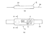
図9(a),(b)に第1の実施形態の変形例に係る電子体温計11の外観を示す。図9(a)は電子体温計11の側面図、図9(b)は同下面図である。
【0047】
電子体温計11は、扁平な略直方体形状をなす。電子体温計11の一方の広面には、端部のほぼ中央部に略四角柱形状のプローブ23が突出形成されている。電子体温計11の他方の広面には、プローブ23とは反対側の端部にLCDからなる表示部4及び電源スイッチ5が配置されている。電子体温計11の長手方向の両端部から固定ベルト24が延びている。固定ベルト24を巻きつけることにより、プローブ23を生体の額等の所定部位に接触した状態で連続的に測定を行うことができる。表示部4には、例えば、10分前の測定値と現在の測定値とを並べて表示するようにしてもよい。このようにすれば、連続的に体温を測定し、その変化を認識することもできる。ICU内に収容されている患者や術後患者のモニターや管理等のほか、常時装着しておくことにより、発熱に注意する必要がある場合に特別な測定動作を行うことなく、リアルタイムで体温を知ることができる。
【0048】
図10は、図9(b)のB−B断面におけるプローブの内部構造を示す図である。略四角柱柱状のプローブ23は、上面部26a及び下面部26bと側面部26cとからなり、薄いSUS材等からなるカバー26によって覆われており、カバー26の上面部26aの下方には温度センサ7が配置されている。カバー26の上面部26aの下方には、カバー上面部26aとの間に温度センサ7を挟んだ状態で略直方体形状の断熱材29が配置されている。断熱材29の下面に接して可変温度ヒータ10が配置され、断熱材29とカバー26の下面部26cとの間は中空部30となっている。
【0049】
このような構成の電子体温計11であれば、乳幼児のように腋の下や舌下にプローブを安定的に保持することが困難な場合であっても、プローブ23を額等の平坦な皮膚表面に接触させることによって容易に測定を行うことができる。また、電子体温計には固定ベルトが設けられているので、常時装着しておくことができる。
【0050】
(第2の実施形態)
図11を参照して本発明の第2の実施形態に係る電子体温計の測定原理について説明する。
【0051】
温度T0の可変温度ヒータ10から、異なる熱伝導率λ1,λ2の断熱材39a,39bをそれぞれ介して生体表面側に位置する部位の温度T1,T2、熱流束q1,q2とを測定することにより、生体表面からの距離hの内部における温度Tbを求める。ここで、断熱材39a,39bの厚さをX、生体の熱伝導率をλb、生体の温度伝導率をαbとすると、
熱伝導の一次元逆問題の基本解の二次項まで含めることにより
【数3】
【数4】
【数5】
T1,T2,dT1/dt,dT2/dtを測定することにより、Tbを求めることができる。
【0052】
このように、可変温度ヒータに対して熱伝導率の異なる断熱材を介して配置され、生体表面に接する部位の温度及びその時間変化を測定することにより、深部温度のような生体内部の温度を測定することができる。
【0053】
ここでは、熱伝導率の異なる断熱材を介して生体表面に接する部位の温度を及びその時間変化を測定し、深部温度を推定しているが、同じ熱伝導率を有し異なる厚さの断熱材を介して、それぞれ生体表面に接する部位の温度及びその時間変化を測定することにより、深部温度を推定するようにしてもよい。
【0054】
図12に本発明の第2の実施形態に係る電子体温計31の外観を示す。外観は、図2に示す第1の実施形態に係る電子体温計1と同じであるので、同様の符号を用いて説明を省略する。
【0055】
電子体温計31のプローブ33は図13に模式的に示すような内部構造を有する。図13は、プローブ33の延長方向に略直交するC−C断面(図12参照)を含み、生体に周囲を覆われた状態を示す。プローブ33は、図3に示す第1の実施形態とほぼ同様の構成を有する。電子体温計31では、カバー6の内周に径方向に分割された半円筒状の熱伝導率の異なる断熱材(第1の断熱材)39a,断熱材(第2の断熱材)39bが配置されている。それぞれの断熱材39a,39bとカバー6との間には温度センサ(第1の温度測定手段)37a及び温度センサ(第2の温度測定手段)37bが配置されている。そして、断熱材の内周面には、それぞれの断熱材39a,39bにまたがるように、可変温度ヒータ10が配置されている。このように、温度センサ37a,37b及び断熱材39a,39bを用いれば、熱流束センサを用いる場合に比べてより低コストで電子体温計31を提供することができる。
【0056】
図14は電子体温計31の内部の回路構成を示すブロック図である。
【0057】
電子体温計31は、制御部12,駆動部13,A/D部14,演算部15,メモリ16,電源部17,可変温度ヒータ10,電源スイッチ5,表示部4,ブザー18に加え、温度センサ37a及び温度センサ37bを備える。温度センサ37a及び温度センサ37bは制御部12からの信号に基づいて駆動部13によって駆動される。
【0058】
図15に電子体温計31の測定処理手順、図16にデータ収集処理の詳細を示す。電子体温計31における測定処理手順及びデータ収集処理は、第1実施形態に係る電子体温計1における場合と同様であるので、説明は省略する。
【0059】
図16に示すフローチャートのステップ210において、連続して算出された複数の深部温度値の差が0.01℃以内であるか否かによって判定するようにすることができる点も第1の実施形態に係る電子体温計の場合と同様である。
【0060】
本実施形態に係る電子体温計のヒータ10も図8に示すように駆動することができる。
【0061】
このように、本実施形態に係る電子体温計31においても、可変温度ヒータ10を制御し、加熱温度を積極的に変化させることにより、電子体温計と生体とが熱平衡となることが妨げられる。従って、電子体温計を継続的に耳に挿入して測定を行う場合、あるいは、耳から取り出した電子体温計を十分な時間間隔を置かずに再度耳に挿入する場合でも、精度の高い内部温度の推定が可能であり、所望のタイミングで内部温度の推定を行うことができる。
【0062】
また、本実施形態に係る電子体温計のプローブ33における温度センサ37a及び37b、断熱材39a及び39b、並びに可変温度ヒータ10の構成は、図9及び図10に示す第1の実施形態の変形例に係る電子体温計にも同様に適用することができる。
【0063】
(第3の実施形態)
図17を参照して本発明の第3の実施形態に係る電子体温計の測定原理について説明する。
【0064】
温度T0の可変温度ヒータ10から、熱伝導率λの断熱材49を介して生体表面側に位置する部位の温度T1,熱流束q1を測定することにより、生体表面からの距離hの内部における温度Tbを求める。
【0065】
熱流束の定義式から、又は熱伝導の一次元逆問題の基本解の一次項までを含めることにより、
【数6】
![]()
【数7】
![]()
ここで、Tb=B,T1=Y,−h/λ=A,q1=Zとおくと、
【数8】
![]()
【0066】
また、熱伝導方程式の差分法から又は熱伝導の一次元逆問題の基本解の二次項までを含めることにより、
【数9】
【数10】
![]()
ここで、Tb=C,T1=Y,−h/λ=A,q1=X1,−(h2/α)=B,(dT/dt)=X2とおくと、
【数11】
![]()
【0067】
0次式であれば、時間変化を追わなくてもよいので、最少1回の測定で深部温度を推定することができる。複数回の測定を行えば0次式でも精度を向上させることができ、高次の式を用いればさらに精度を向上させることができる。
【0068】
熱流束センサとしては、例えば、積層構造や平面展開型の作動型サーモパイル等を用いることができる。
【0069】
図18に本発明の第3の実施形態に係る電子体温計41の外観を示す。外観は図2に示す第1の実施形態に示す電子体温計1と同様であるので、同様の符号を用いて説明を省略する。
【0070】
電子体温計41のプローブ43は図18に模式的に示すような内部構造を有する。図19は、プローブ43の延長方向に略直交するC−C断面(図17参照)を含み、生体に周囲を覆われた状態を示す。プローブ43は、図3に示す第1の実施形態とほぼ同様の構成を有する。断面略円形状のプローブ3の外周はカバー6によって覆われている。カバー6の内周面に温度センサ(温度測定手段)47及び熱流束センサ(熱流束測定手段)48が配置され、さらに内周側には温度センサ47及び熱流束センサ48をカバー6との間に挟むようにして断熱材49が配置されている。断熱材49は円筒状に形成され、内周側は中空部となっている。断熱材9の内周面には、断熱材49を介して温度センサ47及び熱流束センサ48と対向する位置に可変温度ヒータ10が配置されている。
【0071】
図20は電子体温計41の内部の回路構成を示すブロック図である。
【0072】
電子体温計41は、制御部12,駆動部13,A/D部14,演算部15,メモリ16,電源部17,可変温度ヒータ10,電源スイッチ5,表示部4,ブザー18に加え、温度センサ47及び熱流束センサ48を備える。温度センサ47及び熱流束センサ48は制御部12からの信号に基づいて駆動部13によって駆動される。
【0073】
図21に示すフローチャートを参照して、体温測定を行う場合の処理手順について説明する。
【0074】
電源スイッチオン(ステップ301)から電源オフ(ステップ305)までの処理、及び自動的に電源をオフし(ステップ313)、処理を終了するまでの手順は図5に示す第1の実施形態と同様である。
【0075】
また、ステップ310において、連続して算出された複数の深部温度値の差が0.01℃以内であるか否かによって判定するようにすることもできる点も第1の実施形態と同様である。
【0076】
また、図22のデータ収集処理の詳細フローは、第1の実施形態の図7と同様である。
【0077】
本実施形態に係る電子体温計の可変温度ヒータ10も図8に示すように駆動することができる。
【0078】
このように、本実施形態に係る電子体温計41においても、可変温度ヒータ10を制御し、加熱温度を積極的に変化させることにより、電子体温計と生体とが熱平衡となることが妨げられる。従って、電子体温計で継続的に測定を行う場合、あるいは、一度測定した電子体温計で十分な時間間隔を置かずに再度測定する場合でも、精度の高い内部温度の推定が可能であり、所望のタイミングで内部温度の推定を行うことができる。
【0079】
また、本実施形態に係る電子体温計のプローブ43における温度センサ47及び熱流束センサ48、断熱材49、並びに可変温度ヒータ10の構成は、図9及び図10に示す第1の実施形態の変形例に係る電子体温計にも同様に適用することができる。
【0080】
【発明の効果】
以上、説明したように、本発明によれば、所望のタイミングで、内部温度を高精度かつ短時間で推定できる電子体温計を提供することができる。
【図面の簡単な説明】
【図1】図1は本発明の第1の実施形態に係る電子体温計の測定原理を説明する図である。
【図2】図2は本発明の第1の実施形態に係る電子体温計の外観を示す図である。
【図3】図3は本発明の第1の実施形態に係る電子体温計のプローブの内部構造を示す図である。
【図4】図4は本発明の第1の実施形態に係る電子体温計の回路構成を示すブロック図である。
【図5】図5は本発明の第1の実施形態に係る電子体温計の測定処理手順を示すフローチャートである。
【図6】図6(a),(b)は本発明の第1の実施形態に係る電子体温計の表示部の表示例を示す図である。
【図7】図7は本発明の第1の実施形態に係る電子体温計のデータ収集処理の詳細を示すフローチャートである。
【図8】図8(a),(b),(c)は本発明の第1の実施形態に係る電子体温計のヒータの駆動方法を示す図である。
【図9】図9(a),(b)は本発明の第1の実施形態の変形例に係る電子体温計の外観を示す図である。
【図10】図10は本発明の第1の実施形態の変形例に係る電子体温計のプローブの内部構造を示す図である。
【図11】図11は本発明の第2の実施形態に係る電子体温計の測定原理を説明する図である。
【図12】図12は本発明の第2の実施形態に係る電子体温計の外観を示す図である。
【図13】図13は本発明の第2の実施形態に係る電子体温計のプローブの内部構造を示す図である。
【図14】図14は本発明の第2の実施形態に係る電子体温計の回路構成をブロック図である。
【図15】図15は本発明の第2の実施形態に係る電子体温計の測定処理手順を示すフローチャートである。
【図16】図16は本発明の第2の実施形態に係る電子体温計のデータ収集処理の詳細を示すフローチャートである。
【図17】図17は本発明の第3の実施形態に係る電子体温計の測定原理を説明する図である。
【図18】図18は本発明の第2の実施形態に係る電子体温計の外観を示す図である。
【図19】図19は本発明の第3の実施形態に係る電子体温計のプローブの内部構造を示す図である。
【図20】図20は本発明の第3の実施形態に係る電子体温計の回路構成を示すブロック図である。
【図21】図21は本発明の第3の実施形態に係る電子体温計の測定処理手順を示すフローチャートである。
【図22】図22は本発明の第3の実施形態に係る電子体温計のデータ収集処理の詳細を示すフローチャートである。
【符号の説明】
1,11,31 電子体温計
2 本体部
3,23,33 プローブ
4 表示部
7,8,37a,37b,47 温度センサ
9,29,39a,39,49 断熱材
10 ヒータ
12 制御部
13 駆動部
15 演算部
16 メモリ
48 熱流束センサ[0001]
BACKGROUND OF THE INVENTION
The present invention relates to a thermometer that calculates a deep temperature according to a heat conduction equation from temperature information of an in vitro surface.
[0002]
[Prior art]
Conventionally, mercury thermometers and the like used for body temperature measurement normally measure the surface temperature of a living body, which is different from the deep temperature. It was necessary to wait until the temperature reached equilibrium.
[0003]
Further, as disclosed in Japanese Patent Publication No. 7-119656, a method of predicting an equilibrium point by applying a mode of temperature change until the deep part temperature and the surface temperature reach equilibrium is used as a body temperature. Has also been proposed.
[0004]
As body temperature, it is preferable to directly measure the temperature inside the living body. Therefore, a method for measuring the deep temperature is required. Regarding this, there is a method generally known as an inverse problem of heat conduction as a method of estimating the deep body temperature from the surface temperature of the living body, that is, estimating the temperature at a position away from the measurement point. In particular, a solution of a method for obtaining an external temperature in a region between two points from two different temperature measurements is introduced in, for example, Masahiro Shoji, “Heat Transfer Engineering” (Tokyo University Press) p90. An electronic thermometer that estimates the temperature inside the living body using this method is proposed in WO 9850766. The electronic thermometer proposed here estimates not the surface temperature but the temperature inside the living body at high speed.
[0005]
[Problems to be solved by the invention]
However, if the measurement is performed after waiting for the surface temperature to reach equilibrium with the deep temperature, it takes a long time of about 10 minutes to complete the measurement.
[0006]
Also, in the case of a method for predicting body temperature based on the mode of temperature change until the surface temperature and deep temperature reach equilibrium, the time required for measurement is reduced, but about 90 seconds are required. There was a limit in accuracy because it could not cope with the change sufficiently.
[0007]
In addition, the estimation method proposed in WO 9850766 is based on a temperature change due to heat conduction from a living body, and it has been necessary to once separate the thermometer from the living body in order to repeatedly measure.
[0008]
The present invention has been made to solve the problems of the prior art, and an object thereof is to provide an electronic thermometer capable of estimating the internal temperature with high accuracy and in a short time at a desired timing. It is in.
[0009]
[Means for Solving the Problems]
In order to achieve the above object, the present invention directly measures the temperature of the outer surface of the object to be measured in real time, and based on the value thus obtained, it is not possible to directly measure the temperature to be measured such as a deep temperature. Estimate the temperature inside the body. Such an estimation method corresponds to the inverse problem of the heat conduction equation. Evaluate the heat conduction equation as a low-order equation such as a linear equation with a directly measurable physical quantity such as the temperature outside the object to be measured as a variable, and directly measure these physical quantities to determine the internal temperature such as the deep temperature. Is estimated. If at least different measured values corresponding to the number of variables are obtained, the estimation of the internal temperature is reduced to the solution of the simultaneous linear equations, so that it can be calculated accurately and in a short time.
[0010]
The present inventionFirst temperature and secondMeasure temperaturepluralTemperature measuring means;Changing the temperature of at least one of the plurality of temperature measuring means to change the flow of heat between the measurement object and the electronic thermometer.Variable temperature heating means capable of changing the heating temperature;The first temperature measurement value measured a plurality of times and the second temperature measurement valueAn electronic thermometer comprising: an internal temperature estimating means for estimating a temperature inside a measurement object based on a temperature measurement value.
[0011]
As described above, when solving the inverse problem of the heat conduction equation and estimating the internal temperature of the measured object such as the deep temperature of the living body, at least the sum of the variables of the heat conduction equation expressed as a low-order equation However, when the electronic thermometer is continuously brought into contact with the object to be measured, the electronic thermometer and the object to be measured gradually approach thermal equilibrium. For this reason, the change of the measured value with progress of time becomes small. In the present invention, even when the electronic thermometer is continuously brought into contact with the object to be measured and approaches the thermal equilibrium in this way, the heating temperature of the variable temperature heating means is changed to change between the object to be measured and the electronic thermometer. It is possible to obtain a measurement value capable of estimating the internal temperature with high accuracy by changing the flow of heat between them and causing a new state of heat transfer to appear actively. Therefore, by driving and controlling the variable temperature heating means to change the heating temperature, it is possible to estimate the internal temperature with high accuracy in a short time at a desired timing. The drive control of the variable temperature heating means may be such that the heating temperature is continuously changed and the internal temperature can be estimated even if a measurement instruction is given at an arbitrary timing. If body temperature is measured at predetermined time intervals, the variable temperature heating means may be driven and controlled to change the heating temperature in accordance with the measurement timing.
[0012]
Also, the abovepluralThe temperature measurement means includes first and second temperature measurement means, and includes a heat insulating material provided between the first temperature measurement means and the second temperature measurement means, and the first temperature measurement means It is preferable that the temperature of the part approximately the same as the variable temperature heating means is measured, and the second temperature measuring means measures the temperature of the part on the measured object side with a heat insulating material interposed between the variable temperature heating means. is there.
[0013]
As physical quantities that are directly measured to solve the inverse problem of the heat conduction equation, temperatures at different sites can be selected in this way. In addition, by arranging a heat insulating material between the first and second temperature measuring means, a stable thermal gradient can be formed, and the temperature can be kept at a temperature suitable for the measurement, thereby enabling more accurate measurement. It becomes.
[0014]
Also, the abovepluralThe temperature measurement means includes first and second temperature measurement means, a first heat insulating material provided between the heating means and the first temperature measurement means, the heating means, and the second temperature. And a second heat insulating material provided between the measuring means and having a thermal constant different from that of the first heat insulating material, wherein the first temperature measuring means is the first heat measuring means with respect to the heating means. The temperature of the part on the measured object side is measured with the heat insulating material interposed therebetween, and the second temperature measuring means measures the temperature of the part on the measured object side with the second heat insulating material sandwiched with respect to the heating means. Is preferred.
[0015]
As a physical quantity that is directly measured to solve the inverse problem of the heat conduction equation, the temperature of the part sandwiching the heat insulating material having different thermal constants with respect to the heating means can be selected. In addition, by arranging a heat insulating material between the first and second temperature measuring means and the variable temperature heating means, a stable thermal gradient can be formed, and the temperature conditions suitable for measurement can be maintained. High-precision measurement is possible. Here, the thermal constant representing the heat-related characteristics includes, but is not limited to, thermal conductivity and specific heat. In addition, even when the thermal conductivity is the same, there is a case where the thickness of the substance existing between the measurement site inside the living body and the position where the temperature is directly measured has different characteristics regarding heat.
[0017]
As a physical quantity that is directly measured to solve the inverse problem of the heat conduction equation, the temperature and heat flux of the part sandwiching the heat insulating material with respect to the variable temperature heating means can be selected. In addition, a stable thermal gradient is formed by placing a heat insulating material between the variable temperature heating means and the temperature measuring means, and between the variable temperature heating means and the heat flux measuring means, and the temperature conditions are suitable for measurement. Therefore, more accurate measurement is possible.
[0018]
In addition, it is preferable that a member having a high thermal conductivity is provided at a contact portion with the measurement object.
[0019]
The probe may be in contact with the object to be measured, and the probe may have a rod shape or a plate shape.
[0020]
The probe that comes into contact with the body to be measured can have various shapes, but if the subject can maintain the state necessary for measuring body temperature, it can be used for measurement under the armpit or sublingual that is relatively close to the deep temperature. A suitable bar shape may be used, and when it is difficult for the subject to maintain the state necessary for measuring body temperature, such as an infant, it can be easily brought into contact with the skin of the subject like a plate shape. The shape can be made.
[0021]
The internal temperature estimation operation control means for controlling the internal temperature estimation operation, and the internal temperature storage means for storing the estimated internal temperature, wherein the internal temperature estimation control means performs the internal temperature estimation for a predetermined time. Estimated internal as well as at intervalstemperatureIs preferably stored in the internal temperature storage means.
[0022]
As described above, the electronic thermometer according to the present invention can measure the body temperature at an arbitrary timing even when it continuously contacts the body to be measured. By storing the values, it is possible to monitor and manage ICU and postoperative patients. In addition, by always wearing the electronic thermometer according to the present invention, it is possible to know the body temperature in real time without performing a measurement operation when fever is anxious.
[0023]
DETAILED DESCRIPTION OF THE INVENTION
Hereinafter, the present invention will be described based on the illustrated embodiments.
[0024]
(First embodiment)
First, the measurement principle of the electronic thermometer according to the first embodiment of the present invention will be described with reference to FIG.
[0025]
That is, the deep temperature is Tb, the temperature and heat flux at the living body surface are T1 and q1, respectively, and the heat insulating material.9The temperature and heat flux of the part in contact with the surface of the living body through T2 and q2, the density and specific heat of the heat insulating material ρ and c, the heat conductivity of the heat insulating material λ2, the heat conductivity of the living body λ1, Assuming that the thickness h1 is the thickness h2 of the heat insulating material, from the heat quantity conservation law and the heat flux definition formula,
[Expression 1]
DT1When organizing / dt,
[Expression 2]
![]()
[0027]
Where T1, DT1/ Dt, T2Is obtained, the deep temperature TbCan be calculated. At this time, if T2 is changed by the variable temperature heater, T1, DT1/ Dt, T2Can be changed. That is, if the deep temperature is calculated based on the temperature change due to heat conduction from the living body, if the thermometer is continuously worn, the temperature sensor and the living body approach thermal equilibrium, and the temperature change does not occur. T1, DT1Measurement values with different / dt cannot be obtained, and accurate depth temperature estimation becomes difficult. However, as mentioned above, T2If the thermometer is actively changed, even if the thermometer is continuously worn,1, DT1/ Dt, T2Can be obtained at an arbitrary timing, and it is possible to estimate the depth temperature with high accuracy.
[0028]
FIG. 2 shows the appearance of the electronic thermometer according to the first embodiment of the present invention.
[0029]
The
[0030]
The
[0031]
FIG. 4 is a block diagram showing an internal circuit configuration of the
[0032]
The
[0033]
The control unit (internal temperature estimation means, internal temperature estimation operation control means) 12 is composed of a CPU or the like and controls the whole thermometer. The
[0034]
With reference to the flowchart shown in FIG. 5, the process sequence in the case of measuring body temperature is demonstrated.
[0035]
First, when the
[0036]
FIG. 7 shows details of the processing from
[0037]
After the measurement preparation completion is displayed on the
[0038]
In the above procedure, whether or not sufficient data for measurement is collected is determined based on whether or not the calculated values of the depth temperature are continuously the same. The determination may be made based on whether or not the temperature value difference is within 0.01 ° C.
[0039]
Here, as a driving method of the
[0040]
First, as shown in FIG. 8A, the
[0041]
Next, as shown in FIG. 8B, the
[0042]
In addition, as shown in FIG. 8 (c), the
[0043]
The driving method of FIG. 8 is an example, and T used for calculating the deep temperature by driving the heater 10.1, DT1/ Dt, T2Therefore, the driving method of the
[0044]
Further, timing for changing the heating temperature by intermittently repeating a waveform of one period or a part of one period as shown in FIGS. 8A, 8B, and 8C at a predetermined time interval. You may make it measure according to.
[0045]
Thus, in the
[0046]
FIGS. 9A and 9B show the external appearance of an
[0047]
The
[0048]
FIG. 10 is a view showing the internal structure of the probe in the BB cross section of FIG. The substantially square
[0049]
With the
[0050]
(Second Embodiment)
The measurement principle of the electronic thermometer according to the second embodiment of the present invention will be described with reference to FIG.
[0051]
Temperature T0From the
By including up to quadratic terms of the basic solution of the one-dimensional inverse problem of heat conduction
[Equation 3]
[Expression 4]
[Equation 5]
T1, T2, DT1/ Dt, dT2By measuring / dt, TbCan be requested.
[0052]
In this way, the temperature inside the living body, such as the deep temperature, is measured by measuring the temperature of the part in contact with the surface of the living body and the time change thereof, which is arranged via the heat insulating material having different thermal conductivity with respect to the variable temperature heater. Can be measured.
[0053]
Here, the temperature of the part in contact with the surface of the living body through heat insulating materials having different thermal conductivities and the time variation thereof are measured, and the deep temperature is estimated, but the heat insulation having the same thermal conductivity and different thicknesses is estimated. The depth temperature may be estimated by measuring the temperature of the part in contact with the surface of the living body and the change with time through the material.
[0054]
FIG. 12 shows the appearance of an
[0055]
The
[0056]
FIG. 14 is a block diagram showing an internal circuit configuration of the
[0057]
The
[0058]
FIG. 15 shows the measurement processing procedure of the
[0059]
In the
[0060]
The
[0061]
Thus, also in the
[0062]
Further, the configurations of the
[0063]
(Third embodiment)
The measurement principle of the electronic thermometer according to the third embodiment of the present invention will be described with reference to FIG.
[0064]
Temperature T0The temperature T of the part located on the surface side of the living body from the
[0065]
From the definition of heat flux or by including up to the first order term of the basic solution of the one-dimensional inverse problem of heat conduction,
[Formula 6]
![]()
[Expression 7]
![]()
Where Tb= B, T1= Y, -h / λ = A, q1= Z
[Equation 8]
![]()
[0066]
Also, by including from the difference method of the heat conduction equation or to the quadratic terms of the basic solution of the one-dimensional inverse problem of heat conduction,
[Equation 9]
[Expression 10]
![]()
Where Tb= C, T1= Y, -h / λ = A, q1= X1,-(h2/ Α) = B, (dT / dt) = X2After all,
## EQU11 ##
![]()
[0067]
Since it is not necessary to follow a time change if it is a zero-order equation, the depth temperature can be estimated by a minimum of one measurement. If the measurement is performed a plurality of times, the accuracy can be improved even with a zero-order equation, and the accuracy can be further improved by using a higher-order equation.
[0068]
As the heat flux sensor, for example, a laminated structure, a flat-deployment type operation type thermopile, or the like can be used.
[0069]
FIG. 18 shows the appearance of an
[0070]
The
[0071]
FIG. 20 is a block diagram showing an internal circuit configuration of the
[0072]
The
[0073]
With reference to the flowchart shown in FIG. 21, the process sequence in the case of measuring body temperature is demonstrated.
[0074]
The processing from the power switch ON (step 301) to the power OFF (step 305) and the procedure from the automatic power OFF (step 313) to the end of the processing are the same as in the first embodiment shown in FIG. It is.
[0075]
Further, in
[0076]
Further, the detailed flow of the data collection process of FIG. 22 is the same as that of FIG. 7 of the first embodiment.
[0077]
The
[0078]
As described above, also in the
[0079]
The configuration of the
[0080]
【The invention's effect】
As described above, according to the present invention, it is possible to provide an electronic thermometer capable of estimating the internal temperature with high accuracy and in a short time at a desired timing.
[Brief description of the drawings]
FIG. 1 is a diagram for explaining the measurement principle of an electronic thermometer according to a first embodiment of the present invention.
FIG. 2 is a diagram showing an external appearance of the electronic thermometer according to the first embodiment of the present invention.
FIG. 3 is a diagram showing an internal structure of the probe of the electronic thermometer according to the first embodiment of the present invention.
FIG. 4 is a block diagram showing a circuit configuration of the electronic thermometer according to the first embodiment of the present invention.
FIG. 5 is a flowchart showing a measurement processing procedure of the electronic thermometer according to the first embodiment of the present invention.
FIGS. 6A and 6B are diagrams showing a display example of the display unit of the electronic thermometer according to the first embodiment of the present invention.
FIG. 7 is a flowchart showing details of data collection processing of the electronic thermometer according to the first embodiment of the present invention.
FIGS. 8A, 8B, and 8C are diagrams showing a method of driving a heater of the electronic thermometer according to the first embodiment of the present invention.
FIGS. 9A and 9B are views showing the external appearance of an electronic thermometer according to a modification of the first embodiment of the present invention.
FIG. 10 is a diagram showing an internal structure of a probe of an electronic thermometer according to a modification of the first embodiment of the present invention.
FIG. 11 is a diagram for explaining the measurement principle of an electronic thermometer according to a second embodiment of the present invention.
FIG. 12 is a view showing an appearance of an electronic thermometer according to a second embodiment of the present invention.
FIG. 13 is a diagram showing an internal structure of a probe of an electronic thermometer according to a second embodiment of the present invention.
FIG. 14 is a block diagram of a circuit configuration of an electronic thermometer according to a second embodiment of the present invention.
FIG. 15 is a flowchart showing a measurement processing procedure of the electronic thermometer according to the second embodiment of the present invention.
FIG. 16 is a flowchart showing details of data collection processing of the electronic thermometer according to the second embodiment of the present invention.
FIG. 17 is a view for explaining the measurement principle of an electronic thermometer according to a third embodiment of the present invention.
FIG. 18 is a view showing an appearance of an electronic thermometer according to a second embodiment of the present invention.
FIG. 19 is a diagram showing an internal structure of a probe of an electronic thermometer according to a third embodiment of the present invention.
FIG. 20 is a block diagram showing a circuit configuration of an electronic thermometer according to a third embodiment of the present invention.
FIG. 21 is a flowchart showing a measurement processing procedure of an electronic thermometer according to a third embodiment of the present invention.
FIG. 22 is a flowchart showing details of data collection processing of an electronic thermometer according to a third embodiment of the present invention.
[Explanation of symbols]
1,11,31 Electronic thermometer
2 Body
3,23,33 probe
4 display section
7, 8, 37a, 37b, 47 Temperature sensor
9, 29, 39a, 39, 49
10 Heater
12 Control unit
13 Drive unit
15 Calculation unit
16 memory
48 Heat flux sensor
Claims (6)
て前記第1の断熱材を挟んで被測定体側の部位の温度を測定し、前記第2の温度測定手段は前記可変温度加熱手段に対して前記第2の断熱材を挟んで被測定体側の部位の温度を
測定することを特徴とする請求項1に記載の電子体温計。Wherein the plurality of temperature measuring means, and a second temperature measuring means for measuring a first temperature measuring means and said second temperature measuring said first temperature, the variable temperature heating unit and the first A first heat insulating material provided between the temperature measuring means and a temperature constant different from that of the first heat insulating material provided between the variable temperature heating means and the second temperature measuring means. A second heat insulating material, wherein the first temperature measuring means measures the temperature of the part on the measured object side with the first heat insulating material sandwiched with respect to the variable temperature heating means, and the second temperature measuring means. 2. The electronic thermometer according to claim 1, wherein the temperature measuring unit measures the temperature of a portion on the measured object side with the second heat insulating material sandwiched with respect to the variable temperature heating unit.
Priority Applications (1)
| Application Number | Priority Date | Filing Date | Title |
|---|---|---|---|
| JP2002173308A JP4207470B2 (en) | 2001-06-18 | 2002-06-13 | Electronic thermometer |
Applications Claiming Priority (3)
| Application Number | Priority Date | Filing Date | Title |
|---|---|---|---|
| JP2001-184134 | 2001-06-18 | ||
| JP2001184134 | 2001-06-18 | ||
| JP2002173308A JP4207470B2 (en) | 2001-06-18 | 2002-06-13 | Electronic thermometer |
Publications (3)
| Publication Number | Publication Date |
|---|---|
| JP2003075262A JP2003075262A (en) | 2003-03-12 |
| JP2003075262A5 JP2003075262A5 (en) | 2005-10-13 |
| JP4207470B2 true JP4207470B2 (en) | 2009-01-14 |
Family
ID=26617145
Family Applications (1)
| Application Number | Title | Priority Date | Filing Date |
|---|---|---|---|
| JP2002173308A Expired - Fee Related JP4207470B2 (en) | 2001-06-18 | 2002-06-13 | Electronic thermometer |
Country Status (1)
| Country | Link |
|---|---|
| JP (1) | JP4207470B2 (en) |
Families Citing this family (8)
| Publication number | Priority date | Publication date | Assignee | Title |
|---|---|---|---|---|
| US7938783B2 (en) * | 2003-08-19 | 2011-05-10 | Advanced Monitors Corporation | Medical body core thermometer |
| JP4798280B2 (en) * | 2004-09-15 | 2011-10-19 | セイコーエプソン株式会社 | Thermometer, electronic device having thermometer, and body temperature measuring method |
| US7597668B2 (en) | 2006-05-31 | 2009-10-06 | Medisim Ltd. | Non-invasive temperature measurement |
| US8185341B2 (en) | 2008-05-30 | 2012-05-22 | Medisim Ltd. | Surface temperature profile |
| JP5844200B2 (en) * | 2012-03-30 | 2016-01-13 | シチズンホールディングス株式会社 | Contact type internal thermometer |
| JP6272352B2 (en) * | 2012-12-27 | 2018-01-31 | コーニンクレッカ フィリップス エヌ ヴェKoninklijke Philips N.V. | Apparatus and method for determining core temperature of food |
| JP7005513B2 (en) * | 2016-05-18 | 2022-01-21 | コーニンクレッカ フィリップス エヌ ヴェ | Single heat flux sensor device |
| US11744469B2 (en) | 2017-03-31 | 2023-09-05 | Nec Corporation | Thermal diffusion coefficient measuring device, and deep-body thermometer, deep-body temperature measuring device, and deep-body temperature measuring method using same |
-
2002
- 2002-06-13 JP JP2002173308A patent/JP4207470B2/en not_active Expired - Fee Related
Also Published As
| Publication number | Publication date |
|---|---|
| JP2003075262A (en) | 2003-03-12 |
Similar Documents
| Publication | Publication Date | Title |
|---|---|---|
| JP4310962B2 (en) | Electronic thermometer | |
| US6886978B2 (en) | Electronic clinical thermometer | |
| US6890096B2 (en) | Electronic clinical thermometer | |
| KR102630649B1 (en) | Apparatus, systems and methods for non-invasive thermal irradiation | |
| JP4600170B2 (en) | Thermometer and electronic device having thermometer | |
| JP3935915B2 (en) | Method of operating high-speed precision temperature measuring device and human body temperature measuring system | |
| CN102106724B (en) | Electronic clinical thermometer and body temperature measurement method | |
| US4848147A (en) | Thermal transient anemometer | |
| CN104083153A (en) | Thermometer and temperature measurement method | |
| JP2012517012A (en) | Method and system for temperature compensated temperature measurement | |
| JP4207470B2 (en) | Electronic thermometer | |
| JP4798280B2 (en) | Thermometer, electronic device having thermometer, and body temperature measuring method | |
| JP2005098982A (en) | Electronic clinical thermometer | |
| JP4982766B2 (en) | Sensor for thermoelectric property measurement | |
| JP3920662B2 (en) | Electronic thermometer | |
| JPS5951321A (en) | Electronic clinical thermometer | |
| US20230172456A1 (en) | Installation State Determination Method, and Installation State Determination System | |
| WO2022158343A1 (en) | Temperature measurement device, thermometer, temperature measurement method, and temperature attenuation measurement method | |
| JPS6039519A (en) | Electronic clinical thermometer | |
| KR200363872Y1 (en) | Sensor for a thermometer | |
| JPS63177029A (en) | Electronic clinical thermometer | |
| JP2003503694A (en) | Fast response thermometer | |
| JPS6036926A (en) | Electronic clinical thermometer | |
| JPS61274233A (en) | Temperature detector | |
| JPS62267627A (en) | Electronic clinical thermometer |
Legal Events
| Date | Code | Title | Description |
|---|---|---|---|
| A521 | Request for written amendment filed |
Free format text: JAPANESE INTERMEDIATE CODE: A523 Effective date: 20050608 |
|
| A621 | Written request for application examination |
Free format text: JAPANESE INTERMEDIATE CODE: A621 Effective date: 20050608 |
|
| A977 | Report on retrieval |
Free format text: JAPANESE INTERMEDIATE CODE: A971007 Effective date: 20071015 |
|
| A131 | Notification of reasons for refusal |
Free format text: JAPANESE INTERMEDIATE CODE: A131 Effective date: 20071023 |
|
| A521 | Request for written amendment filed |
Free format text: JAPANESE INTERMEDIATE CODE: A523 Effective date: 20071225 |
|
| TRDD | Decision of grant or rejection written | ||
| A01 | Written decision to grant a patent or to grant a registration (utility model) |
Free format text: JAPANESE INTERMEDIATE CODE: A01 Effective date: 20080930 |
|
| A01 | Written decision to grant a patent or to grant a registration (utility model) |
Free format text: JAPANESE INTERMEDIATE CODE: A01 |
|
| A61 | First payment of annual fees (during grant procedure) |
Free format text: JAPANESE INTERMEDIATE CODE: A61 Effective date: 20081013 |
|
| R150 | Certificate of patent or registration of utility model |
Ref document number: 4207470 Country of ref document: JP Free format text: JAPANESE INTERMEDIATE CODE: R150 Free format text: JAPANESE INTERMEDIATE CODE: R150 |
|
| FPAY | Renewal fee payment (event date is renewal date of database) |
Free format text: PAYMENT UNTIL: 20111031 Year of fee payment: 3 |
|
| FPAY | Renewal fee payment (event date is renewal date of database) |
Free format text: PAYMENT UNTIL: 20111031 Year of fee payment: 3 |
|
| FPAY | Renewal fee payment (event date is renewal date of database) |
Free format text: PAYMENT UNTIL: 20121031 Year of fee payment: 4 |
|
| FPAY | Renewal fee payment (event date is renewal date of database) |
Free format text: PAYMENT UNTIL: 20121031 Year of fee payment: 4 |
|
| FPAY | Renewal fee payment (event date is renewal date of database) |
Free format text: PAYMENT UNTIL: 20131031 Year of fee payment: 5 |
|
| LAPS | Cancellation because of no payment of annual fees |