JP4206353B2 - Steering damper device - Google Patents
Steering damper device Download PDFInfo
- Publication number
- JP4206353B2 JP4206353B2 JP2004085399A JP2004085399A JP4206353B2 JP 4206353 B2 JP4206353 B2 JP 4206353B2 JP 2004085399 A JP2004085399 A JP 2004085399A JP 2004085399 A JP2004085399 A JP 2004085399A JP 4206353 B2 JP4206353 B2 JP 4206353B2
- Authority
- JP
- Japan
- Prior art keywords
- steering
- damper
- cylindrical
- head pipe
- cylindrical damper
- Prior art date
- Legal status (The legal status is an assumption and is not a legal conclusion. Google has not performed a legal analysis and makes no representation as to the accuracy of the status listed.)
- Expired - Lifetime
Links
- 238000013016 damping Methods 0.000 claims description 66
- 230000007935 neutral effect Effects 0.000 description 15
- 230000000694 effects Effects 0.000 description 5
- 230000008602 contraction Effects 0.000 description 4
- 238000010586 diagram Methods 0.000 description 2
- 230000004048 modification Effects 0.000 description 2
- 238000012986 modification Methods 0.000 description 2
- 230000006835 compression Effects 0.000 description 1
- 238000007906 compression Methods 0.000 description 1
- 230000001419 dependent effect Effects 0.000 description 1
- 230000000149 penetrating effect Effects 0.000 description 1
Images


Classifications
-
- B—PERFORMING OPERATIONS; TRANSPORTING
- B62—LAND VEHICLES FOR TRAVELLING OTHERWISE THAN ON RAILS
- B62K—CYCLES; CYCLE FRAMES; CYCLE STEERING DEVICES; RIDER-OPERATED TERMINAL CONTROLS SPECIALLY ADAPTED FOR CYCLES; CYCLE AXLE SUSPENSIONS; CYCLE SIDE-CARS, FORECARS, OR THE LIKE
- B62K21/00—Steering devices
- B62K21/08—Steering dampers
-
- F—MECHANICAL ENGINEERING; LIGHTING; HEATING; WEAPONS; BLASTING
- F16—ENGINEERING ELEMENTS AND UNITS; GENERAL MEASURES FOR PRODUCING AND MAINTAINING EFFECTIVE FUNCTIONING OF MACHINES OR INSTALLATIONS; THERMAL INSULATION IN GENERAL
- F16F—SPRINGS; SHOCK-ABSORBERS; MEANS FOR DAMPING VIBRATION
- F16F9/00—Springs, vibration-dampers, shock-absorbers, or similarly-constructed movement-dampers using a fluid or the equivalent as damping medium
- F16F9/06—Springs, vibration-dampers, shock-absorbers, or similarly-constructed movement-dampers using a fluid or the equivalent as damping medium using both gas and liquid
- F16F9/064—Units characterised by the location or shape of the expansion chamber
-
- F—MECHANICAL ENGINEERING; LIGHTING; HEATING; WEAPONS; BLASTING
- F16—ENGINEERING ELEMENTS AND UNITS; GENERAL MEASURES FOR PRODUCING AND MAINTAINING EFFECTIVE FUNCTIONING OF MACHINES OR INSTALLATIONS; THERMAL INSULATION IN GENERAL
- F16F—SPRINGS; SHOCK-ABSORBERS; MEANS FOR DAMPING VIBRATION
- F16F9/00—Springs, vibration-dampers, shock-absorbers, or similarly-constructed movement-dampers using a fluid or the equivalent as damping medium
- F16F9/32—Details
- F16F9/34—Special valve constructions; Shape or construction of throttling passages
- F16F9/348—Throttling passages in the form of annular discs or other plate-like elements which may or may not have a spring action, operating in opposite directions or singly, e.g. annular discs positioned on top of the valve or piston body
Landscapes
- Engineering & Computer Science (AREA)
- General Engineering & Computer Science (AREA)
- Mechanical Engineering (AREA)
- Steering Devices For Bicycles And Motorcycles (AREA)
- Fluid-Damping Devices (AREA)
- Vibration Dampers (AREA)
Description
本発明は,自動二輪車等の小型車両に用いられるステアリングダンパ装置に関するものである。 The present invention relates to a steering damper device used in a small vehicle such as a motorcycle.
自動二輪車においては,ハンドル操作によって,前輪を支持するフロントフォークを,車体フレーム前端のヘッドパイプに回動自在に挿通されたステアリングステムを中心として回動させることにより,ステアリングが行われるようになっている。そのような自動二輪車には,ハンドル操作によって回動するステアリング側部材と,ハンドル操作によっても回動しない車体側部材との間に,ステアリングダンパ装置が装備されることがある。その場合,そのステアリングダンパ装置には,ハンドルの切れ角が小さくかつ角速度の遅い通常の走行においては減衰モーメントをほとんど発生させないこと,ハンドルの切れ角が大きくかつ角速度が速い領域では高い減衰モーメントを発生させること,スピードが遅く,細かなターンが連続して比較的ハンドル切れ角が大きくなるような状況では,低速域の減衰モーメントを小さく設定することによりハンドル操作の負担が極力抑えられるようにすること,操舵されたステアリングを戻すときには減衰モーメントをほとんど発生させないようにすること,などが求められる。そのために,従来の自動二輪車用ステアリングダンパ装置の中には,揺動型ダンパを用い,複雑に減衰力を変化させるバイパスを設けることによって上述のような要求に応えるようにしているものがある。 In motorcycles, steering is performed by turning the front fork that supports the front wheels around a steering stem that is rotatably inserted into the head pipe at the front end of the vehicle body frame by operating the steering wheel. Yes. Such a motorcycle may be equipped with a steering damper device between a steering side member that is turned by a handle operation and a vehicle body side member that is not turned by a handle operation. In that case, the steering damper device generates almost no damping moment during normal driving with a small steering angle and a low angular velocity, and a high damping moment in a region where the steering angle is large and the angular velocity is high. In a situation where the speed is slow and the turning angle is relatively large due to continuous small turns, the steering operation load should be minimized as much as possible by setting the damping moment in the low speed range small. , When returning the steered steering, it is required to generate almost no damping moment. For this reason, some of the conventional steering damper devices for motorcycles use a swinging damper and provide a bypass for changing the damping force in a complicated manner to meet the above-described requirements.
しかしながら,そのような揺動型ダンパを用いたステアリングダンパ装置は,構造が複雑で,価格が高く,しかも,大型で重量も大きくなるために,他の部品の配置等が制約される場合も生じることが考えられる。 However, the steering damper device using such a swinging damper has a complicated structure, is expensive, and has a large size and a large weight, which may restrict the arrangement of other components. It is possible.
自動二輪車用のステアリングダンパ装置を,単純な構造で価格も低い筒型ダンパによって構成するようにしたものも古くから知られている(例えば,特許文献1参照)。そのステアリングダンパ装置は,ダンパケースと,そのダンパケース内を摺動するダンパロッドとからなる筒型ダンパを用いたもので,そのダンパケースが車体側部材であるヘッドパイプあるいはステアリング側部材であるフォークブリッジのいずれか一方に回動可能に連結され,ダンパロッドがその他方に回動可能に連結される。その場合,フォークブリッジ側の連結点は,そのフォークブリッジの左右いずれかの端部寄りの位置とされる。 2. Description of the Related Art For a long time, it has been known that a steering damper device for a motorcycle is configured by a cylindrical damper having a simple structure and a low price (for example, see Patent Document 1). The steering damper device uses a cylindrical damper comprising a damper case and a damper rod that slides inside the damper case. The damper case is a head pipe that is a vehicle body side member or a fork that is a steering side member. A bridge rod is rotatably connected to one of the bridges, and a damper rod is rotatably connected to the other side. In this case, the connecting point on the fork bridge side is a position closer to either the left or right end of the fork bridge.
そのようなステアリングダンパ装置によれば,例えばハンドルを右回りに切ると筒型ダンパが収縮し,左回りでは伸長するので,いずれの側でもダンパ作用を発生させることができる。そして,それによって,その回動限で減衰力を得ることができる。
一般に,筒型ダンパは,そのダンパの収縮行程あるいは伸長行程において一様の減衰力を発生させる。したがって,上記特許文献1に記載されているように,ハンドルの回動方向に応じて,一方側では筒型ダンパを収縮させ,他方側では伸長させるようにしたものでは,ハンドルを操舵角0°から右に切ったときと左に切ったときとで同様の特性にすることは可能であるが,ハンドルを操舵角0°から操舵するときと操舵角0°に戻すときとで異なる減衰力が得られるようにすることは困難である。また,ハンドル操舵角に対して角度依存特性を持たせることも困難である。しかも,上記特許文献1に記載されているようなものでは,その構造上,長いダンパストロークが必要となるので,コンパクトなレイアウトとすることができない。
In general, a cylindrical damper generates a uniform damping force during the contraction stroke or extension stroke of the damper. Therefore, as described in
本発明は,かかる事情に鑑みてなされたもので,構造の簡単な通常の筒型ダンパを用いながら,所望の特性を持たせることのできるステアリングダンパ装置を提供することを目的とするものである。 The present invention has been made in view of such circumstances, and an object of the present invention is to provide a steering damper device capable of providing desired characteristics while using a normal cylindrical damper having a simple structure. .
上記目的を達成するために,請求項1に係る本発明は,ダンパロッドがダンパケース内を摺動する筒型ダンパを,ハンドル操作によりステアリングステムを中心として回動するステアリング側部材と,ハンドル操作によっても回動しない車体側部材との間に設けてなるステアリングダンパ装置において,前記ステアリングステムを回動自在に支持する前記車体側部材としてのヘッドパイプの前方にそのヘッドパイプの長手方向に沿って前記筒型ダンパが配置されるとともに,この筒型ダンパの一端部が前記ヘッドパイプに,またその他端部が,前記ヘッドパイプにその軸方向で隣接する前記ステアリング側部材にそれぞれ回動自在に連結され,ハンドル操舵角が0°から増加するのに応じて前記筒型ダンパが最短位置から前記ヘッドパイプの長手方向に沿って伸長することを特徴とする。
To achieve the above object, the present invention according to
また,請求項2に係る本発明は,上記請求項1に係るステアリングダンパ装置において,ハンドル操舵角が0°の近傍においては前記筒型ダンパの中心軸線が前記ステアリングステムの中心軸線を含む平面上にほぼ位置するように,前記筒型ダンパが配設されていることを特徴とする。 According to a second aspect of the present invention, in the steering damper device according to the first aspect, when the steering angle is near 0 °, the central axis of the cylindrical damper is on a plane including the central axis of the steering stem. The cylindrical damper is arranged so as to be positioned substantially at the center.
さらに,請求項3に係る本発明は,上記請求項2に係るステアリングダンパ装置において,ハンドル操舵角がの近傍において前記筒型ダンパの中心軸線が車体前後方向に延びる車体中心面にほぼ沿うように,前記筒型ダンパが配設されていることを特徴とする。
Furthermore, the present invention according to
さらにまた,請求項4に係る本発明は,上記請求項1に係るステアリングダンパ装置において,前記筒型ダンパが,ハンドル操舵角が0°の位置からハンドルを左右いずれの側に操舵したときにも前記ダンパロッドが前記ダンパケース内を同一の方向に摺動するようにして取り付けられていることを特徴とする。
Furthermore, the present invention according to
さらにまた,請求項5に係る本発明は,上記請求項4に係るステアリングダンパ装置において,前記ダンパロッドのハンドル操舵角に対する摺動量が,ハンドル操舵角が0°の近傍においては小さく,ハンドル操舵角が0°から離れるに従って大きくなるようにされていることを特徴とする。
Furthermore, the present invention according to
さらにまた,請求項6に係る本発明は,上記請求項4に係るステアリングダンパ装置において,前記筒型ダンパから前記ステアリング側部材に作用する減衰力が,ハンドル操舵角が0°の近傍においては小さく,ハンドル操舵角が0°から離れるに従って大きくなるようにされていることを特徴とする。
Furthermore, the present invention according to
さらにまた,請求項7に係る本発明は,上記請求項1に係るステアリングダンパ装置において,前記ヘッドパイプに,前方に向けて突出するステーが設けられ,このステーに前記筒型ダンパの前記一端部が連結されることを特徴とする。
Furthermore, the present invention according to
さらにまた請求項8に係る本発明は,上記請求項1又は6に係るステアリングダンパ装置において,前記ステアリング側部材に,前方に向けて突出するステーが設けられ,このステーに前記筒型ダンパ10の前記他端部が連結されることを特徴とする。
Furthermore, the present invention according to
また,請求項9に係る本発明は,ダンパロッドがダンパケース内を摺動する筒型ダンパを,ハンドル操作によりステアリングステムを中心として回動するステアリング側部材と,ハンドル操作によっても回動しない車体側部材との間に設けてなるステアリングダンパ装置において,前記ステアリングステムを回動自在に支持する前記車体側部材としてのヘッドパイプの前方にそのヘッドパイプの長手方向に沿って前記筒型ダンパが配置されるとともに,この筒型ダンパの一端部が前記ヘッドパイプに,またその他端部が,前記ヘッドパイプにその軸方向で隣接する前記ステアリング側部材にそれぞれ回動自在に連結され,ハンドル操舵角が0°から増加するのに応じて前記筒型ダンパが最短位置から前記ヘッドパイプの長手方向に沿って伸長するとともに,ハンドル操舵角が0°から増加するとき,操舵角に対する前記筒型ダンパの伸び量が操舵初期には小さく,操舵中盤では漸次増大し,操舵後半では,前記ステアリング軸まわりのモーメントアームの大幅な減少により減衰モーメントの上昇が鈍くなることを特徴とする。 According to a ninth aspect of the present invention, there is provided a tubular damper in which a damper rod slides in a damper case, a steering side member that rotates around a steering stem by a handle operation, and a vehicle body that does not rotate by a handle operation. the steering damper device in which provided between the side members, the steering stem a rotatably supported to the longitudinal direction on the tubular damper I along the head pipe in front of the head pipe as the vehicle body-side member The cylindrical damper has one end portion connected to the head pipe and the other end portion rotatably connected to the steering side member adjacent to the head pipe in the axial direction thereof. extended I along but from the cylindrical damper is shortest position according to increases from 0 ° to the longitudinal direction of the head pipe When the steering angle of the steering wheel increases from 0 °, the extension amount of the cylindrical damper with respect to the steering angle is small in the initial stage of steering, gradually increases in the middle of the steering, and in the latter half of the steering, the moment arm around the steering shaft It is characterized in that the increase of the damping moment becomes dull due to a large decrease.
上記請求項1に係る本発明によれば,操舵角0°からハンドルを右に切るときと左に切るときとのいずれにおいても,筒型ダンパは,最短位置からヘッドパイプの長手方向に沿って伸長することになるので,左右対称の特性を持たせることができる。そして,ハンドルを戻すときにはその逆となるが,筒型ダンパは,収縮行程と伸長行程とでは異なる減衰力特性を設定することができるので,ハンドルを切るときには減衰モーメントが発生し,ハンドルを戻すときには減衰モーメントが小さくなるようにすることができる。したがって,自動二輪車等のステアリングダンパ装置に求められる前述のような要求を満足させることができる。
According to the present invention according to the
また,筒型ダンパがヘッドパイプの前方にその長手方向に沿って設けられるので,そのステアリングダンパ装置によって車両のデザイン等が妨げられることを軽減することができる。 Further, since the cylindrical damper is provided I along the longitudinal direction in front of the head pipe, it is possible to reduce the design of the vehicle is prevented by the steering damper device.
上記請求項2に係る本発明によれば,筒型ダンパの中心軸線がステアリングステムの中心軸線を含む平面上に位置するように筒型ダンパが配設されることにより,その筒型ダンパは,操舵角0°からハンドルを右に切るときと左に切るときとで対称に伸縮することになるので,そのステアリングダンパ装置に左右対称の特性を持たせることができる。 According to the second aspect of the present invention, the cylindrical damper is disposed such that the central axis of the cylindrical damper is located on a plane including the central axis of the steering stem. Since the steering angle is expanded and contracted symmetrically when the steering wheel is turned to the right and when the steering wheel is turned to the left from the steering angle of 0 °, the steering damper device can have a symmetrical characteristic.
上記請求項3に係る本発明によれば,筒型ダンパが車体前後方向の中心面にほぼ沿って設けられるので,そのステアリングダンパ装置が車体の左右に大きくはみ出すことが防止されることになり,そのステアリングダンパ装置全体をコンパクトに配置することができる。 According to the third aspect of the present invention, since the cylindrical damper is provided substantially along the center plane in the longitudinal direction of the vehicle body, the steering damper device is prevented from protruding greatly to the left and right of the vehicle body, The entire steering damper device can be arranged compactly.
上記請求項4に係る本発明によれば,操舵角0°からハンドルを右に切るときと左に切るときとのいずれにおいても,筒型ダンパは伸長のみをすることになるので,前述した請求項1に係る本発明の効果と同様の効果を得ることができる。
According to the fourth aspect of the present invention, the cylindrical damper only extends when the steering wheel is turned to the right or left when the steering angle is 0 °. The effect similar to the effect of this invention which concerns on claim |
上記請求項5に係る本発明によれば,ハンドル操舵角が0°から離れるに従ってハンドル操舵角に対するダンパロッドの摺動量が大きくなるようにされるので,ハンドル切れ角が大きくかつ角速度が速い領域では高い減衰モーメントを発生させることができ,自動二輪車等のステアリングダンパ装置に求められる前述した要求を満足させることができる。 According to the fifth aspect of the present invention, the amount of sliding of the damper rod with respect to the steering angle of the steering wheel increases as the steering angle of the steering wheel departs from 0 °. Therefore, in a region where the steering angle is large and the angular velocity is high. A high damping moment can be generated, and the above-described requirements for a steering damper device such as a motorcycle can be satisfied.
上記請求項6に係る本発明によれば,筒型ダンパからステアリング側部材に作用する減衰力が,ハンドル操舵角が0°の近傍においては小さく,ハンドル操舵角が0°から離れるに従って大きくなるようにされるので,ハンドルの切れ角が小さい領域では減衰力はほとんど発生させず,ハンドル切れ角の大きい領域では大きな減衰力を発生させることができ,自動二輪車等のステアリングダンパ装置に求められる前述した要求を満足させることができる。 According to the sixth aspect of the present invention, the damping force acting on the steering side member from the cylindrical damper is small when the steering angle of the steering wheel is 0 °, and increases as the steering angle of the steering wheel is separated from 0 °. Therefore, almost no damping force is generated in the region where the steering angle of the steering wheel is small, and large damping force can be generated in the region where the steering angle of the steering wheel is large, which is required for a steering damper device such as a motorcycle as described above. The request can be satisfied.
上記請求項9に係る本発明によれば,請求項1に係る発明の効果を達成する上,筒型ダンパからステアリング側部材に作用する減衰力は,ハンドル操舵角0°から操舵初期に小さく,操舵中盤で漸次増加していき,そして操舵後半では,ステアリング軸まわりのモーメントアームが大幅に小さくなるので,減衰モーメントの上昇が鈍くなり,かくしてステアリングダンパ装置に求められる要求特性を満足させることができる。 According to the ninth aspect of the present invention, in addition to achieving the effect of the first aspect of the present invention, the damping force acting on the steering side member from the cylindrical damper is small from the steering wheel steering angle of 0 ° in the initial stage of steering. In the latter half of steering, the moment arm around the steering shaft becomes significantly smaller, so the damping moment rises slowly, thus satisfying the required characteristics required for the steering damper device. .
以下,本発明の実施の形態を,添付図面に示す本発明の好適な実施例に基づいて説明する。 Hereinafter, embodiments of the present invention will be described based on preferred examples of the present invention shown in the accompanying drawings.
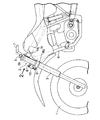
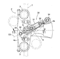
図中,図1〜図8は本発明によるステアリングダンパ装置の実施例を示すもので,図1はそのステアリングダンパ装置を備えた自動二輪車の要部を示す側面図,図2は図1の矢印2方向から見たフロントフォーク部の正面図,図3は図2の3−3線に沿う筒型ダンパ部分の断面図,図4および図5はその筒型ダンパの作用を説明するための拡大図,図6はハンドルを左に切ったときの状態を示す図2と同様の正面図,図7は図6の7−7線に沿う断面図,図8はそのステアリングダンパ装置の特性曲線図である。 1 to 8 show an embodiment of a steering damper device according to the present invention, FIG. 1 is a side view showing a main part of a motorcycle equipped with the steering damper device, and FIG. 2 is an arrow in FIG. FIG. 3 is a sectional view of the cylindrical damper portion taken along line 3-3 in FIG. 2, and FIGS. 4 and 5 are enlarged views for explaining the operation of the cylindrical damper. 6 is a front view similar to FIG. 2 showing the state when the steering wheel is turned to the left, FIG. 7 is a sectional view taken along line 7-7 in FIG. 6, and FIG. 8 is a characteristic curve diagram of the steering damper device. It is.
図1および図2に示すように,自動二輪車の前輪1を支持するフロントフォーク2は,左右のフォークパイプ3,3と,その上端部を連結するフォークブリッジ4とを備えている。フォークブリッジ4は,上下に離間して平行に配置されたトップブリッジ4aとボトムブリッジ4bとからなり,それらブリッジ4a,4bの左右方向中央部間には,それらを一体に連結するステアリングステム5が配置された。そのステアリングステム5は,車体フレーム6の前端に設けられるヘッドパイプ6hに回動自在に支承されている。そして,トップブリッジ4aに,ステアリング用のハンドル7が取り付けられている。こうして,ハンドル7の操作により,フロントフォーク2がステアリングステム5を中心として左右に回動し,そのフロントフォークに支持されている前輪1がそれとともに回動することによって,自動二輪車のステアリングが行われるようになっている。
As shown in FIGS. 1 and 2, the
ヘッドパイプ6hには,その下端部寄りの位置に,前方に向けて突出するステー8が設けられている。そのステー8は,車体前後方向に延びる車体中心面上に配置されている。また,ボトムブリッジ4bにも,その左右方向中央部に,前方に向けて突出するステー9が設けられている。そして,それらのステー8,9間に,筒型ダンパ10が配設されている。すなわち,筒型ダンパ10は,ヘッドパイプ6hの前方に,そのヘッドパイプ6hの長手方向に沿うようにして配設されている。
The
図3に示すように,筒型ダンパ10は,ダンパケース11と,そのダンパケース11内を摺動するダンパロッド12とからなるもので,そのダンパケース11が球面継手13を介してヘッドパイプ6h側,すなわち車体側のステー8に回動自在に連結され,ダンパロッド12が球面継手14を介してボトムブリッジ4b側,すなわちステアリング側のステー9に回動自在に連結されている。そして,ダンパケース11内を摺動するダンパロッド12の中心軸線,すなわち筒型ダンパ10の中心軸線D1が,球面継手13,14の各中心を通るようにされている。このようにして,筒型ダンパ10は,ハンドル7の操作時にも回動しない車体フレーム6と,ハンドル7の操作に伴って回動するフロントフォーク2との間に取り付けられている。図2に示すように,その筒型ダンパ10は,ハンドル7が中立位置にあるとき,すなわちハンドル操舵角が0°のとき,最も収縮した状態,すなわちダンパロッド12が最短位置となり,しかも,筒型ダンパ10の中心軸線D1がステアリングステム5およびヘッドパイプ6hの中心軸線Sに平行となるようにされている。したがって,そのときには,筒型ダンパ10の中心軸線D1が,ステアリングステム5の中心軸線Sを含む車体前後方向の平面,すなわち車体前後方向に延びる車体中心面上に位置するようになっている。 筒型ダンパ10のダンパケース11は,図3に示すように,ダンパ室15と,そのダンパ室15に油路16を介して連通するリザーバ室17とを備えている。それらダンパ室15およびリザーバ室17内にはオイルが封入されている。リザーバ室17の下面はピストン18によって形成され,そのピストン18が,その下方のガス室に封入される圧縮ガス19により上方に向けて押圧付勢されている。また,ダンパ室15は,ダンパロッド12の先端に取り付けられたピストン20によって上下の2室15a,15bに区画されている。そのピストン20には,上下に貫通する複数の開口21,21…とその開口21の下端を開閉制御するバルブ22とが設けられている。図4および図5に示すように,そのバルブ22は,比較的小径の弁孔23aを有する弁板23と,その弁孔23aを開閉するゴム板24と,弁板23を開口21の閉塞位置に向けて付勢する板ばね25とによって構成されている。さらに,ピストン20には,開口21とダンパ室15の下室15bとを常に連通させるオリフィス26が設けられている。
As shown in FIG. 3, the
このような構成を有する筒型ダンパ10においては,伸長するときには,ダンパロッド12の先端に取り付けられているピストン20がダンパ室15の下方側に向けて摺動することにより,そのダンパ室15の下室15b内の圧力が高くなるので,図4に矢印で示すように,下室15b内のオイルが弁孔23aを通り,開口21を経て上室15aへと流れる。そして,その弁孔23aを通るときの抵抗により,減衰力が発生する。また,収縮するときには,ダンパ室15の上室15a内の圧力が高くなるので,図5に仮想線で示すように,弁板23が板ばね25の付勢力に抗して下方に変形する。その結果,開口21が開くことになり,上室15a内のオイルが開口21を通って下室15bへと流れる。したがって,このときには,減衰力はほとんど発生しない。
In the
次に,このように構成されたステアリングダンパ装置の作用について説明する。 Next, the operation of the steering damper device configured as described above will be described.
上述のように,ハンドル7が中立位置にあるとき,すなわちハンドル操舵角が0°のときには,筒型ダンパ10は最も収縮した最短の状態にある。この状態で,ハンドル7を例えば左に切ると,図6に示すように,フロントフォーク2が,車体フレーム6のヘッドパイプ6hに回動自在に挿通されているステアリングステム5を中心として左方向に回動する。したがって,フロントフォーク2のフォークブリッジ4を構成するボトムブリッジ4bも同様に回動し,その左右方向の中央部に設けられているステー9と筒型ダンパ10のダンパロッド12とを連結する球面継手14が車体前後方向の車体中心面上から外れる。一方,ヘッドパイプ6hに設けられているステー8と筒型ダンパ10のダンパケース11とを連結する球面継手13は,ハンドル7の操作をしてもヘッドパイプ6hが回動しないので,元の位置,すなわち車体前後方向の車体中心面上にある。その結果,筒型ダンパ10が伸長して,ダンパロッド12がダンパケース11内を図3において下方に摺動することになり,減衰力が発生する。
As described above, when the
また,ハンドル7を右に切ったときにも,筒型ダンパ10は同様に伸長し,ダンパロッド12がダンパケース11内を図3において下方に摺動する。したがって,減衰力が発生する。このように,この筒型ダンパ10は,ハンドル操舵角が0°の位置からハンドル7を左右いずれの側に操舵したときにも,ダンパロッド12がダンパケース11内を同一の方向に摺動するようにして設けられている。
Further, when the
しかも,ハンドル7を右に切ったときも左に切ったときも,そのハンドル7の切れ角,すなわち操舵角が同じであれば,筒型ダンパ10の伸び量は同じとなる。したがって,その減衰力特性は,図8に示すように,左右対称となる。
Moreover, when the
そして,右あるいは左に切ったハンドル7を中立位置に戻すときには,いずれの場合も,筒型ダンパ10は収縮し,ダンパロッド12がダンパケース11内を図3において上方に摺動することになる。上述のように,その筒型ダンパ10は,収縮時にはほとんど減衰力を発生しないようにされている。したがって,操舵されたステアリングを戻すときには,減衰力はほとんど生じない。このようにして,このステアリングダンパ装置により,ハンドル7を操舵角0°から右あるいは左に切るときにはいずれの場合にも減衰力が発生し,ハンドル7を操舵角0°に戻すときには減衰力が小さくなるようにすることができる。
When the
図8は,筒型ダンパ10をある位置に取り付けて,ハンドル7をある一定速度で左右に操舵したときの減衰モーメントを計算により求めた結果を示すものである。ダンパ10の減衰力は,ダンパ10の伸縮速度に対して一定の割合で増加していく特性とした。
FIG. 8 shows the result of calculating the damping moment when the
図8に示すように,このステアリングダンパ装置によれば,ハンドル7の切れ角が小さいところでは発生する減衰モーメントは小さく,切れ角が大きくなるに従って大きな減衰モーメントが発生する。すなわち,筒型ダンパ10からステアリング側部材であるフロントフォーク2に作用する減衰力は,ハンドル操舵角が0°の近傍においては小さく,ハンドル操舵角が0°から離れるに従って大きくなる。しかも,その間は滑らかに連続する。
As shown in FIG. 8, according to this steering damper device, the damping moment generated is small where the turning angle of the
このように,ハンドル7を中立位置から操舵していくとき,その初期には減衰モーメントがほとんど発生しない理由は,ハンドル7の中立位置近辺ではハンドル7の切れ角に対して筒型ダンパ10の伸び量が小さいことによる。そして,中盤では,ハンドル7の切れ角に対してダンパストロークが漸次増大するので,減衰力も徐々に大きくなる。すなわち,このステアリングダンパ装置においては,ダンパロッド12のハンドル操舵角に対する摺動量が,ハンドル操舵角が0°の近傍においては小さく,ハンドル操舵角が0°から離れるに従って大きくなるようにされている。また,後半は,ステアリング軸まわりのモーメントアームが大幅に小さくなるので,減衰モーメントの上昇が鈍くなる。
Thus, when the
このようにして,このステアリングダンパ装置により,自動二輪車のステアリングダンパ装置に求められる前述したような要求を満足させることが可能となる。 In this manner, this steering damper device can satisfy the above-described requirements for a steering damper device for a motorcycle.
また,ヘッドパイプ6hの前方に比較的短い筒型ダンパ10を取り付けるのみでよいので,コンパクトかつ軽量に構成することができ,デザイン等を阻害するおそれも少ない。しかも,筒型ダンパ10は,生産性が高いので,そのコストも低減させることができる。
Further, since it is only necessary to attach the relatively short
図9〜図13は本発明の一要素の筒型ダンパを備えるステアリングダンパ装置の第1参考例を示すもので,図9はそのステアリングダンパ装置を備えた自動二輪車の要部を示す側面図,図10は図9の矢印10方向から見たフロントフォーク部の平面図,図11は図10の11−11線に沿う筒型ダンパの断面図,図12はハンドルを左に切ったときの状態を示す図10と同様の平面図,図13は図12の13−13線に沿う断面図である。
FIGS. 9 to 13 show a first reference example of a steering damper device including a cylindrical damper as one element of the present invention, and FIG. 9 is a side view showing a main part of a motorcycle including the steering damper device. 10 is a plan view of the front fork portion viewed from the direction of the
なお,この第1参考例において,前記実施例と対応する部分には同一の符号を付すことにより,重複する説明は省略する。 In the first reference example, the same reference numerals are given to the portions corresponding to the above-described embodiment, and the duplicated explanation is omitted.
図9および図10に示すように,この第1参考例の場合には,フォークブリッジ4の上部をなすトップブリッジ4aの上面中央部の,ステアリングステム5よりも前方の位置に,上方に突出するステー28が設けられている。また,車体フレーム6のヘッドパイプ6hには,その上端部から後方に向けて延出する延出部6jが設けられ,その延出部6jの上面に,上方に突出するステー29が設けられている。そして,それらのステー28,29間に,筒型ダンパ30が配設されている。図11に示すように,その筒型ダンパ30は,ダンパケース31と,そのダンパケース31内を摺動するダンパロッド32とからなるもので,そのダンパケース31が球面継手33を介してステアリング側部材であるトップブリッジ4a側のステー28に回動自在に連結され,ダンパロッド32が球面継手34を介して車体側部材であるヘッドパイプ6h側のステー29に回動自在に連結されている。しかも,ダンパロッド32の中心軸線,すなわち筒型ダンパ30の中心軸線D2が,球面継手33,34の各中心を通るようにされている。このようにして,筒型ダンパ30は,ハンドル7の操作時にも回動しない車体フレーム6と,ハンドル7の操作に伴って回動するフロントフォーク2との間に取り付けられている。図10に示すように,その筒型ダンパ30は,ハンドル7が中立位置にあるとき,すなわちハンドル操舵角が0°のとき,最も伸長した状態すなわちダンパロッド32が最長位置となり,しかも,ステアリングステム5およびヘッドパイプ6hを跨いで,車体前後方向の車体中心面上に位置するようにされている。したがって,そのときには,筒型ダンパ30の中心軸線D2が,ステアリングステム5の中心軸線Sを含む車体前後方向の平面,すなわち車体前後方向に延びる車体中心面上に位置するようになっている。
As shown in FIGS. 9 and 10, in the case of the first reference example, it projects upward at a position in front of the
筒型ダンパ30の構造は,バルブ35が,筒型ダンパ30の収縮時に減衰力を発生し,筒型ダンパ30の伸長時には減衰力をほとんど発生しない構成とされている以外は,前記実施例の筒型ダンパ10と同様であるので,その詳細な説明は省略する。また,その他の構成も前記実施例と同様である。
The structure of the
このような構成を有するステアリングダンパ装置においては,上述のように,ハンドル7が中立位置にあるときには,筒型ダンパ30は最も伸長した最長の状態にある。この状態から,ハンドル7を例えば左に切ると,図12に示すように,フロントフォーク2が,車体フレーム6のヘッドパイプ6hに回動自在に挿通されているステアリングステム5を中心として左方向に回動する。したがって,フロントフォーク2のフォークブリッジ4を構成するトップブリッジ4aも同様に回動し,その左右方向の中央部に設けられているステー28と筒型ダンパ30のダンパケース31とを連結する球面継手33が車体前後方向の車体中心面上から外れる。一方,ヘッドパイプ6hの延出部6jに設けられているステー29と筒型ダンパ30のダンパロッド32とを連結する球面継手34は,ハンドル7の操作をしてもヘッドパイプ6hが回動しないので,元の位置,すなわち車体前後方向の車体中心面上にある。その結果,筒型ダンパ30が収縮して,ダンパロッド32がダンパケース31内を図11において左方に摺動することになり,減衰力が発生する。また,ハンドル7を右に切ったときにも,筒型ダンパ30は同様に収縮し,ダンパロッド32がダンパケース31内を図11において左方に摺動する。したがって,減衰力が発生する。このように,この筒型ダンパ30も,ハンドル操舵角が0°の位置からハンドル7を左右いずれの側に操舵したときにも,ダンパロッド32がダンパケース31内を同一の方向に摺動するようにして設けられている。
In the steering damper device having such a configuration, as described above, when the
しかも,ハンドル7を右に切ったときも左に切ったときも,そのハンドル7の切れ角,すなわち操舵角が同じであれば,筒型ダンパ30の収縮量は同じとなる。したがって,その減衰力特性は左右対称となる。
Moreover, when the
そして,右あるいは左に切ったハンドル7を中立位置に戻すときには,いずれの場合も,筒型ダンパ30は伸長し,ダンパロッド32がダンパケース31内を図11において右方に摺動することになる。上述のように,その筒型ダンパ30は,伸長時にはほとんど減衰力を発生しないようにされている。したがって,操舵されたステアリングを戻すときには,減衰力はほとんど生じない。このようにして,この第1参考例のステアリングダンパ装置によっても,ハンドル7を切るときには減衰力が発生し,ハンドル7を戻すときには減衰力が小さくなるようにすることができる。 しかも,このステアリングダンパ装置においても,ダンパロッド32のハンドル操舵角に対する摺動量は,ハンドル操舵角が0°の近傍においては小さく,ハンドル操舵角が0°から離れるに従って大きくなる。また,筒型ダンパ30からステアリング側部材であるフロントフォーク2に作用する減衰力は,ハンドル操舵角が0°の近傍においては小さく,ハンドル操舵角が0°から離れるに従って大きくなる。したがって,このステアリングダンパ装置により,自動二輪車のステアリングダンパ装置に求められる前述したような要求を満足させることが可能となる。
When the
また,筒型ダンパ30が前後方向に設けられるので,そのステアリングダンパ装置は車体フレーム6にほぼ沿うように配置されることになり,そのステアリングダンパ装置によって他の部品の配置等が制限されることを少なくすることができる。
Further, since the
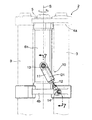
図14および図15は本発明の一要素の筒型ダンパを備えるステアリングダンパ装置の第3実施例を示すもので,図14はそのステアリングダンパ装置を備えた自動二輪車のフロントフォーク部の平面図,図15は図14の矢印15方向から見た側面図である。
14 and 15 show a third embodiment of a steering damper device having a cylindrical damper as one element of the present invention. FIG. 14 is a plan view of a front fork portion of a motorcycle equipped with the steering damper device. 15 is a side view seen from the direction of
なお,この第2参考例において,第1参考例と対応する部分には同一の符号を付すことにより,重複する説明は省略する。 In the second reference example, parts corresponding to those in the first reference example are denoted by the same reference numerals, and redundant description is omitted.
図14および図15に示すように,この第2参考例の場合には,ヘッドパイプ6hの上端部から後方に向けて延出する延出部6jの上面に,ほぼ三角形をなすリンクレバー38が,水平軸39を介して回動自在に支持されている。そして,そのリンクレバー38と,ヘッドパイプ6hとともに車体フレーム6を構成する左右のメインフレーム6m,6m間のダウンチューブ6dとの間に,筒型ダンパ40が配設されている。その筒型ダンパ40は,ダンパケース41と,そのダンパケース41内を摺動するダンパロッド42とからなるもので,そのダンパケース41が水平軸43を介してリンクレバー38の後端部に回動自在に連結され,ダンパロッド42が水平軸44を介してダウンチューブ6dの上端面に回動自在に連結されている。一方,リンクレバー38の前端部上面には,リンクロッド45が球面継手46を介して回動自在に連結されており,そのリンクロッド45の他端が,フォークブリッジ4の上部をなすトップブリッジ4aの上面中央部の,ステアリングステム5よりも前方の位置に,球面継手47を介して回動自在に連結されている。
As shown in FIGS. 14 and 15, in the case of the second reference example, a
このようにして,筒型ダンパ40は,ハンドル操作によりステアリングステム5を中心として回動するステアリング側部材のフォークブリッジ4に連結されるとともに,リンクレバー38とリンクロッド45とを介して,ハンドル操作によっても回動しない車体フレーム6に連結されている。そのリンクロッド45は,ハンドル7が中立位置にあるとき,すなわちハンドル操作角が0°のとき,リンクロッド45の両端の連結部である球面継手46,47の各中心を結ぶ直線L1が,ステアリングステム5の中心軸線Sを含み車体前後方向に延びる車体中心面上に位置するように配設されている。
In this way, the
また,その筒型ダンパ40は,収縮するとき減衰力を発生し,伸長するときにはほとんど減衰力を発生しないものとされている。
Further, the
その他の構成は第1参考例と同様である。 Other configurations are the same as those of the first reference example.
このように構成されたステアリングダンパ装置においては,例えば左にハンドル7を切ると,フロントフォーク2がステアリングステム5の中心軸線Sを中心として左方向に回動し,トップブリッジ4aが図14の二点鎖線位置へと回動するので,そのトップブリッジ4aの前部中央に結合されている球面継手47が,図14に矢印で示すように移動する。その結果,その球面継手47に連結されているリンクロッド45により,リンクレバー38に結合されている球面継手46が後方に向けて押圧されることになり,そのリンクレバー38が,水平軸39を中心として図15に矢印で示すように回動する。したがって,筒型ダンパ40が収縮し,その筒型ダンパ40からステアリング側部材のトップブリッジ4aに減衰力が加えられる。また,ハンドル7を右に切ったときにも,リンクレバー38側の球面継手46が後方に向けて押されるので,同様に筒型ダンパ40が収縮し,減衰力が発生する。
In the steering damper device configured as described above, for example, when the
そして,右あるいは左に切ったハンドル7を中立位置に戻すときには,いずれの場合も筒型ダンパ40が伸長するので,減衰力はほとんど生じない。
When the
このようにして,この第2参考例のステアリングダンパ装置によっても,操舵するときには減衰力が発生し,操舵されたステアリングを戻すときには減衰力がほとんど生じないようにすることができる。そして,このステアリングダンパ装置の場合には,ステアリング側部材の運動がリンクロッド45およびリンクレバー38を介して筒型ダンパ40に伝えられるようになるので,筒型ダンパ40をステアリング側部材から離して,しかも任意の方向に配置することが可能となり,上記実施例のように,メインフレーム6m,6m間のデッドスペース等を利用した筒型ダンパ40の配置を図ることも可能となる。
In this way, even with the steering damper device of the second reference example, it is possible to generate a damping force when steering, and hardly generate a damping force when returning the steered steering. In the case of this steering damper device, the movement of the steering side member is transmitted to the
図16および図17は本発明の一要素の筒型ダンパを備えるステアリングダンパ装置の第3参考例を示すもので,図16はそのステアリングダンパ装置を備えた自動二輪車の,フロントフォークのフォークブリッジ部分の側面図,図17は図16の矢印17方向から見た正面図である。
FIGS. 16 and 17 show a third reference example of a steering damper device having a cylindrical damper as one element of the present invention. FIG. 16 shows a fork bridge portion of a front fork of a motorcycle having the steering damper device. FIG. 17 is a front view seen from the direction of
なお,この第3参考例において,前記実施例と対応する部分には同一の符号を付すことにより,重複する説明は省略する。 In the third reference example, the same reference numerals are given to the portions corresponding to the above-described embodiment, and the duplicated explanation is omitted.
図16および図17に示すように,この第3参考例の場合には,ヘッドパイプ6hの上下方向中央部から前方に向けて突出するステー8aの前端部に,ほぼ三角形をなすリンクレバー48が,水平軸49を介して回動自在に支持されている。そして,そのリンクレバー48と,ヘッドパイプ6hの上端部との間に,筒型ダンパ50が配設されている。その筒型ダンパ50は,ダンパケース51と,そのダンパケース51内を摺動するダンパロッド52とからなるもので,そのダンパケース51が水平軸53を介してヘッドパイプ6hの上端部前面に回動自在に連結され,ダンパロッド52が水平軸54を介してリンクレバー48の前端部に回動自在に連結されている。一方,リンクレバー48の下端部前面には,リンクロッド55が球面継手56を介して回動自在に連結されており,そのリンクロッド55の他端が,フォークブリッジ4の下部をなすボトムブリッジ4bの左右方向中央部前面に,球面継手57を介して回動自在に連結されている。
As shown in FIGS. 16 and 17, in the case of the third reference example, a
このようにして,筒型ダンパ50は,ハンドル操作によっても回動しない車体フレーム6に連結されるとともに,リンクレバー48とリンクロッド55とを介して,ハンドル操作によりステアリングステム5を中心として回動するステアリング側部材のフォークブリッジ4に連結されている。そのリンクロッド55は,ハンドル7が中立位置にあるとき,すなわちハンドル操舵角が0°のとき,リンクロッド55の両端の連結部である球面継手56,57の各中心を結ぶ直線L2が,ステアリングステム5の中心軸線Sを含み車体前後方向に延びる車体中心面上に位置するように配設されている。
In this manner, the
また,その筒型ダンパ50は,伸長するとき減衰力を発生し,収縮するときにはほとんど減衰力を発生しないものとされている。
In addition, the
その他の構成は前記実施例と同様である。 Other configurations are the same as those in the above embodiment.
このように構成されたステアリングダンパ装置においては,例えば左にハンドル7を切ると,フロントフォーク2がステアリングステム5の中心軸線Sを中心として左方向に回動し,ボトムブリッジ4bが同様に回動するので,そのボトムブリッジ4bの前部中央に結合されている球面継手57が,図17に二点鎖線で示す位置へと移動する。その結果,その球面継手57に連結されているリンクロッド55により,リンクレバー48に結合されている球面継手56が引き下げられることになり,そのリンクレバー48が,水平軸49を中心として図16に矢印で示すように回動する。したがって,筒型ダンパ50が伸長し,その筒型ダンパ50からステアリング側部材のボトムブリッジ4bに減衰力が加えられる。また,ハンドル7を右に切ったときにも,リンクレバー48側の球面継手56が引き下げられるので,同様に筒型ダンパ50が伸長し,減衰力が発生する。 そして,右あるいは左に切ったハンドル7を中立位置に戻すときには,いずれの場合も筒型ダンパ50が収縮するので,減衰力はほとんど生じない。
In the steering damper device configured as described above, for example, when the
このようにして,この第3参考例のステアリングダンパ装置によっても,操舵するときには減衰力が発生し,操舵されたステアリングを戻すときには減衰力がほとんど生じないようにすることができる。そして,このステアリングダンパ装置の場合には,ステアリング側部材の運動がリンクロッド55およびリンクレバー48を介して筒型ダンパ50に伝えられるようになるので,筒型ダンパ50をステアリング側部材から離して,しかも任意の方向に配置することが可能となる。したがって,筒型ダンパ50の配置の自由度を一層高めることができる。
In this way, even with the steering damper device of the third reference example, it is possible to generate a damping force when steering, and hardly generate a damping force when returning the steered steering. In the case of this steering damper device, the movement of the steering side member is transmitted to the
図18は本発明の一要素の筒型ダンパを備えるステアリングダンパ装置の第4参考例を示すもので,そのステアリングダンパ装置を備えた自動二輪車のフロントフォーク部の平面図である。 FIG. 18 is a plan view of a front fork portion of a motorcycle including the steering damper device, showing a fourth reference example of the steering damper device including the cylindrical damper as one element of the present invention.
なお,この第4参考例は,前述した第1参考例における筒型ダンパ30の配置の位置および方向を変えただけの変形例であり,ほとんどの構成は第1参考例と同様であるので,第1参考例と対応する部分には同一の符号を付すこととして,重複する説明は省略する。
The fourth reference example is a modification in which the position and direction of the arrangement of the
図18に示すように,この第4参考例の場合には,第1参考例におけるステー28と同様に上端に球面継手33が取り付けられたステー(図示せず)が,フォークブリッジ4のトップブリッジ4aの上面の,左右方向中央部から左側に偏った位置に設けられている。そして,その球面継手33により,筒型ダンパ30のダンパケース31が,ロッド58を介して回動自在に連結支持されている。一方,車体フレーム6には,その右側面から右方に向けて延出する延出部6kが設けられており,その延出部6kの上面に,第1参考例におけるステー29と同様の上方に突出するステー(図示せず)が設けられている。そして,そのステーに,筒型ダンパ30のダンパロッド32が球面継手34を介して回動自在に連結されている。
As shown in FIG. 18, in the case of this fourth reference example, a stay (not shown) having a spherical joint 33 attached to the upper end is the top bridge of the
このようにして,この参考例の場合には,ハンドル操舵角が0°のときにも筒型ダンパ30の中心軸線D2が車体中心面に対して角度をなすように,筒型ダンパ30が配設されている。ただし,その場合にも,ハンドル操舵角が0°のときには,筒型ダンパ30の中心軸線D2がステアリングステム5の中心軸線Sと交わるようにされる。すなわち,ハンドル操舵角が0°のとき,筒型ダンパ30の中心軸線D2とステアリングステム5の中心軸線Sとが同一平面上に位置するようにされる。
Thus, in the case of this reference example, the
筒型ダンパ30がこのように配設されたステアリングダンパ装置においても,ハンドル操舵角が0°の状態からハンドル7を例えば左に切ると,ステアリング側のトップブリッジ4aがステアリングステム5の中心軸線Sを中心として左側に回動して,図18に二点鎖線で示すような状態となるので,球面継手33が矢印で示すように車体後方側に移動する。したがって,筒型ダンパ30が収縮し,減衰力が発生する。また,ハンドル7を右に切ったときにも,筒型ダンパ30は同様に収縮するので,減衰力が発生する。そして,右あるいは左に切ったハンドル7を中立位置に戻すときには,いずれの場合も筒型ダンパ30が伸長することになるので,減衰力はほとんど発生しないようにすることができる。
Also in the steering damper device in which the
このように,第1参考例のようなステアリングダンパ装置の場合にも,その筒型ダンパ30は,必ずしもハンドル7が中立位置にあるとき車体の前後方向中心面上に位置するように配置する必要はなく,車体の前後方向中心面から多少ずらして配置することもできる。
As described above, even in the case of the steering damper device as in the first reference example, the
さらに,筒型ダンパ30は,フォークブリッジ4のボトムブリッジ4b下面と車体フレーム6との間に設けるようにすることもできる。
Further, the
図19は本発明の一要素の筒型ダンパを備えるステアリングダンパ装置の第5参考例を示すもので,そのステアリングダンパ装置を備えた自動二輪車のフロントフォーク部の正面図である。 FIG. 19 is a front view of a front fork portion of a motorcycle including the steering damper device, showing a fifth reference example of the steering damper device including the cylindrical damper as one element of the present invention.
なお,この第5参考例は,前述した前記実施例における筒型ダンパ10の配置位置を変えただけの変形例であり,その他の構成は前記実施例と同様であるので,前記実施例と対応する部分には同一の符号を付すこととして,重複する説明は省略する。
The fifth reference example is a modification in which the arrangement position of the
図19に示すように,この第5参考例の場合には,ヘッドパイプ6hの左側面に,左方向に向けて突出するステー59が設けられている。また,ボトムブリッジ4bの上面には,その左右方向中央部から左側に偏った位置に,上方に向けて突出するステー60が設けられている。そして,ヘッドパイプ6h側のステー59に,球面継手13を介して筒型ダンパ10のダンパケース11が回動自在に連結され,ボトムブリッジ4b側のステー60に,球面継手14を介して筒型ダンパ10のダンパロッド12が回動自在に連結されている。その筒型ダンパ10は,ハンドル操舵角が0°のとき筒型ダンパ10の中心軸線D1がステアリングステム5の中心軸線Sと平行となるようにするなどにより,ハンドル操舵角が0°の近傍において筒型ダンパ10の中心軸線D1とステアリングステム5の中心軸線Sとがほぼ同一平面上に位置するようにされている。
As shown in FIG. 19, in the case of the fifth reference example, a
筒型ダンパ10をこのような配置としたステアリングダンパ装置においても,ハンドル7を操舵角0°から左右いずれかの側に切ると,筒型ダンパ10は常に伸長する。そして,右あるいは左に切ったハンドル7を中立位置に戻すときには,いずれの場合も筒型ダンパ10は収縮する。したがって,ハンドル7を切るときには減衰力が発生し,切られたハンドル7を戻すときにはほとんど減衰力が発生しないようにすることができる。
Even in the steering damper device in which the
このように,筒型ダンパ10を車体中心面から離して配置したステアリングダンパ装置によっても,前記実施例の基本的な効果と同様の効果は得ることができる。すなわち,ハンドル操舵角が0°の近傍において筒型ダンパ10の中心軸線D1とステアリングステム5の中心軸線Sとがほぼ同一平面上に位置するようにされてさえいれば,車体の前後方向中心面からは多少ずれていてもよい。
Thus, the same effect as the basic effect of the above-described embodiment can be obtained also by the steering damper device in which the
さらに,筒型ダンパ10は,フォークブリッジ4のトップブリッジ4aと車体フレーム6との間に設けるようにすることもできる。
Further, the
以上,本発明の好適実施例について説明したが,本発明はその実施例に限定されることなく,本発明の範囲内で種々の実施例が可能である。 Although the preferred embodiments of the present invention have been described above, the present invention is not limited to these embodiments, and various embodiments are possible within the scope of the present invention.
たとえば,筒型ダンパ10は,前記実施例のようにダンパ室15の一側部にリザーバ室17を設けたもののほか,ダンパ室の外周にリザーバ室を設けた二重管式のものを用いることもできる。また,リザーバ室17側に設けられるピストン18付勢用の圧縮ガス19の代わりに圧縮スプリングを用いてもよく,それらを両用してもよい。さらに,本発明は,上記実施例のような自動二輪車のほか,四輪バギー車などの他の車両にも適用することができる。
For example, the
1・・前輪
2・・フロントフォーク
4・・フォークブリッジ(ステアリング側部材)
4a・・トップブリッジ
4b・・ボトムブリッジ
5・・ステアリングステム
6・・車体フレーム(車体側部材)
6h・・ヘッドパイプ
10・・筒型ダンパ
11・・ダンパケース
12・・ダンパロッド
D1・・筒型ダンパの中心軸線
S・・ステアリングステムの中心軸線
1 ・ ・
4a ···
6h ・ ・
Claims (9)
前記ステアリングステム(5)を回動自在に支持する前記車体側部材(6)としてのヘッドパイプ(6h)の前方にそのヘッドパイプ(6h)の長手方向に沿って前記筒型ダンパ(10)が配置されるとともに,この筒型ダンパ(10)の一端部が前記ヘッドパイプ(6h)に,またその他端部が,前記ヘッドパイプ(6h)にその軸方向で隣接する前記ステアリング側部材(4)にそれぞれ回動自在に連結され,ハンドル操舵角が0°から増加するのに応じて前記筒型ダンパ(10)が最短位置から前記ヘッドパイプ(6h)の長手方向に沿って伸長することを特徴とする,ステアリングダンパ装置。 The cylindrical damper (10) in which the damper rod (12) slides in the damper case (11) is also operated by the steering side member (4) that rotates about the steering stem (5) by the steering operation and the steering operation. In the steering damper device provided between the vehicle body side member (6) which does not rotate,
The steering stem (5) the tubular damper I longitudinal direction along the head pipe in front of the head pipe as the vehicle body-side member rotatably supported to (6) (6h) (6h) (10) Is disposed, and one end portion of the cylindrical damper (10) is adjacent to the head pipe (6h), and the other end portion is adjacent to the head pipe (6h) in the axial direction thereof. ) to be respectively rotatably connected, said tubular damper according to the steering angle is increased from 0 ° (10) is extended I along the shortest position in the longitudinal direction of the head pipe (6h) A steering damper device characterized by
前記ステアリングステム(5)を回動自在に支持する前記車体側部材(6)としてのヘッドパイプ(6h)の前方にそのヘッドパイプ(6h)の長手方向に沿って前記筒型ダンパ(10)が配置されるとともに,この筒型ダンパ(10)の一端部が前記ヘッドパイプ(6h)に,またその他端部が,前記ヘッドパイプ(6h)にその軸方向で隣接する前記ステアリング側部材(4)にそれぞれ回動自在に連結され,ハンドル操舵角が0°から増加するのに応じて前記筒型ダンパ(10)が最短位置から前記ヘッドパイプ(6h)の長手方向に沿って伸長するとともに,ハンドル操舵角が0°から増加するとき,操舵角に対する前記筒型ダンパ(10)の伸び量が操舵初期には小さく,操舵中盤では漸次増大し,操舵後半では,前記ステアリング軸まわりのモーメントアームの大幅な減少により減衰モーメントの上昇が鈍くなることを特徴とする,ステアリングダンパ装置。 The cylindrical damper (10) in which the damper rod (12) slides in the damper case (11) is also operated by the steering side member (4) that rotates about the steering stem (5) by the steering operation and the steering operation. In the steering damper device provided between the vehicle body side member (6) which does not rotate,
The steering stem (5) the tubular damper I longitudinal direction along the head pipe in front of the head pipe as the vehicle body-side member rotatably supported to (6) (6h) (6h) (10) Is disposed, and one end portion of the cylindrical damper (10) is adjacent to the head pipe (6h), and the other end portion is adjacent to the head pipe (6h) in the axial direction thereof. ) to be respectively rotatably connected, with the steering angle is the cylindrical damper (10) is extended I along the shortest position in the longitudinal direction of the head pipe (6h) in response to increases from 0 ° When the steering angle of the steering wheel increases from 0 °, the extension amount of the cylindrical damper (10) with respect to the steering angle is small in the initial stage of steering, gradually increases in the middle of the steering, and in the latter half of the steering, the steering Steering damper device characterized in that the increase in damping moment becomes dull due to a significant decrease in moment arm around the shaft.
Priority Applications (9)
| Application Number | Priority Date | Filing Date | Title |
|---|---|---|---|
| JP2004085399A JP4206353B2 (en) | 2003-08-26 | 2004-03-23 | Steering damper device |
| TW093119209A TWI284610B (en) | 2003-08-26 | 2004-06-29 | Steering damper device |
| KR1020040062126A KR100558423B1 (en) | 2003-08-26 | 2004-08-06 | Steering damper device |
| CN2007100876970A CN101041376B (en) | 2003-08-26 | 2004-08-09 | Steering damper device |
| MXPA04007696A MXPA04007696A (en) | 2003-08-26 | 2004-08-09 | Steering damper device. |
| CNB2004100563597A CN100344499C (en) | 2003-08-26 | 2004-08-09 | Steering damper apparatus |
| CA002476975A CA2476975C (en) | 2003-08-26 | 2004-08-09 | Steering damper device |
| BR0403253-5A BRPI0403253A (en) | 2003-08-26 | 2004-08-16 | Steering Damping Device |
| US10/921,082 US7052027B2 (en) | 2003-08-26 | 2004-08-18 | Steering damper apparatus, and motorcycle including same |
Applications Claiming Priority (2)
| Application Number | Priority Date | Filing Date | Title |
|---|---|---|---|
| JP2003301072 | 2003-08-26 | ||
| JP2004085399A JP4206353B2 (en) | 2003-08-26 | 2004-03-23 | Steering damper device |
Related Child Applications (1)
| Application Number | Title | Priority Date | Filing Date |
|---|---|---|---|
| JP2006068309A Division JP4199244B2 (en) | 2003-08-26 | 2006-03-13 | Steering damper device |
Publications (2)
| Publication Number | Publication Date |
|---|---|
| JP2005096735A JP2005096735A (en) | 2005-04-14 |
| JP4206353B2 true JP4206353B2 (en) | 2009-01-07 |
Family
ID=34220734
Family Applications (1)
| Application Number | Title | Priority Date | Filing Date |
|---|---|---|---|
| JP2004085399A Expired - Lifetime JP4206353B2 (en) | 2003-08-26 | 2004-03-23 | Steering damper device |
Country Status (8)
| Country | Link |
|---|---|
| US (1) | US7052027B2 (en) |
| JP (1) | JP4206353B2 (en) |
| KR (1) | KR100558423B1 (en) |
| CN (1) | CN100344499C (en) |
| BR (1) | BRPI0403253A (en) |
| CA (1) | CA2476975C (en) |
| MX (1) | MXPA04007696A (en) |
| TW (1) | TWI284610B (en) |
Cited By (1)
| Publication number | Priority date | Publication date | Assignee | Title |
|---|---|---|---|---|
| JP2011148384A (en) * | 2010-01-21 | 2011-08-04 | Honda Motor Co Ltd | Steering damper device for saddle riding vehicle |
Families Citing this family (17)
| Publication number | Priority date | Publication date | Assignee | Title |
|---|---|---|---|---|
| JP4467050B2 (en) * | 2003-06-25 | 2010-05-26 | 本田技研工業株式会社 | Steering damper device for motorcycles |
| JP4206353B2 (en) * | 2003-08-26 | 2009-01-07 | 本田技研工業株式会社 | Steering damper device |
| JP4234045B2 (en) * | 2004-03-23 | 2009-03-04 | 本田技研工業株式会社 | Steering damper device |
| JP4921801B2 (en) | 2006-02-01 | 2012-04-25 | 本田技研工業株式会社 | Rear wheel suspension system for motorcycles |
| JP5002320B2 (en) * | 2006-07-26 | 2012-08-15 | 本田技研工業株式会社 | Vehicle number plate |
| JP4825623B2 (en) | 2006-08-30 | 2011-11-30 | 本田技研工業株式会社 | Vehicle steering damper mounting structure |
| JP4726746B2 (en) | 2006-08-30 | 2011-07-20 | 本田技研工業株式会社 | Vehicle steering damper mounting structure |
| JP4914730B2 (en) | 2007-01-30 | 2012-04-11 | 本田技研工業株式会社 | Saddle-type vehicle with steering damper |
| JP5033456B2 (en) | 2007-03-30 | 2012-09-26 | 本田技研工業株式会社 | Steering damper mounting structure |
| US7793957B2 (en) * | 2007-06-29 | 2010-09-14 | Kayaba Industry Co., Ltd. | Steering damping device |
| AR079383A1 (en) | 2010-12-27 | 2012-01-25 | Fischer Hugo Alfredo | STEERING STABILIZER DEVICE FOR VEHICLES WITH COLUMN AND HANDLEBAR. |
| DE102011009142B4 (en) * | 2011-01-21 | 2017-03-16 | Edgar Uden | Stabilization system for two-wheelers |
| US9238494B2 (en) * | 2012-09-24 | 2016-01-19 | Yamaha Hatsudoki Kabushiki Kaisha | Vehicle |
| JP6256837B2 (en) * | 2014-03-10 | 2018-01-10 | 本田技研工業株式会社 | Steering structure for saddle-ride type vehicles |
| US9393901B2 (en) * | 2014-07-21 | 2016-07-19 | Kostal Of America | Turn signal systems and methods |
| DE102019101612A1 (en) * | 2019-01-23 | 2020-07-23 | Bayerische Motoren Werke Aktiengesellschaft | Tilt-decoupled steering device of a motorcycle |
| JP7324099B2 (en) * | 2019-09-24 | 2023-08-09 | 本田技研工業株式会社 | Steering mechanism and wheelchair provided with the same |
Family Cites Families (14)
| Publication number | Priority date | Publication date | Assignee | Title |
|---|---|---|---|---|
| US615961A (en) * | 1898-12-13 | Steering-gear for bicycles | ||
| US2087535A (en) * | 1936-04-09 | 1937-07-20 | Dall John | Stabilizer |
| DE1244004B (en) * | 1960-06-10 | 1967-07-06 | Bayerische Motoren Werke Ag | Hydraulic steering damper for motor vehicles, especially for two-wheeled vehicles |
| DE2338720C3 (en) * | 1973-07-31 | 1979-03-08 | Bayerische Motoren Werke Ag, 8000 Muenchen | Hydraulic steering damper for two-wheeled vehicles, in particular motorcycles |
| DE2710651C3 (en) * | 1977-03-11 | 1981-06-25 | Bayerische Motoren Werke AG, 8000 München | Hydraulic steering damper for two-wheeled vehicles |
| JPS644633Y2 (en) * | 1980-09-01 | 1989-02-06 | ||
| US4558878A (en) * | 1983-09-23 | 1985-12-17 | Motrenec Donald L | All terrain cycle with steering stabilizer |
| JPS644633A (en) | 1987-06-26 | 1989-01-09 | Shunji Onishi | Bonding of polyolefin resin with other high-molecular material |
| JPH0699873A (en) * | 1992-09-17 | 1994-04-12 | Suzuki Motor Corp | Steering damper device for motorcycle |
| US5383676A (en) * | 1993-09-02 | 1995-01-24 | Valentino; Thomas J. | Centering apparatus for front wheel of three wheeled vehicle |
| IT237852Y1 (en) * | 1997-08-07 | 2000-09-29 | Crc Ct Ricerche Cagiva S A | STEERING DAMPER OF A MOTORCYCLE WITH A CONSTANTLY ORTHOGONAL AXIS TO THE LONGITUDINAL PLAN OF THE VEHICLE SYMMETRY |
| JP2003237672A (en) * | 2002-02-20 | 2003-08-27 | Yamaha Motor Co Ltd | Motorcycle steering damper |
| JP4206353B2 (en) * | 2003-08-26 | 2009-01-07 | 本田技研工業株式会社 | Steering damper device |
| JP4234045B2 (en) * | 2004-03-23 | 2009-03-04 | 本田技研工業株式会社 | Steering damper device |
-
2004
- 2004-03-23 JP JP2004085399A patent/JP4206353B2/en not_active Expired - Lifetime
- 2004-06-29 TW TW093119209A patent/TWI284610B/en not_active IP Right Cessation
- 2004-08-06 KR KR1020040062126A patent/KR100558423B1/en not_active IP Right Cessation
- 2004-08-09 MX MXPA04007696A patent/MXPA04007696A/en active IP Right Grant
- 2004-08-09 CN CNB2004100563597A patent/CN100344499C/en not_active Expired - Fee Related
- 2004-08-09 CA CA002476975A patent/CA2476975C/en not_active Expired - Fee Related
- 2004-08-16 BR BR0403253-5A patent/BRPI0403253A/en not_active Application Discontinuation
- 2004-08-18 US US10/921,082 patent/US7052027B2/en active Active
Cited By (2)
| Publication number | Priority date | Publication date | Assignee | Title |
|---|---|---|---|---|
| JP2011148384A (en) * | 2010-01-21 | 2011-08-04 | Honda Motor Co Ltd | Steering damper device for saddle riding vehicle |
| US8684385B2 (en) | 2010-01-21 | 2014-04-01 | Honda Motor Co., Ltd. | Steering damper device for saddle riding vehicle |
Also Published As
| Publication number | Publication date |
|---|---|
| JP2005096735A (en) | 2005-04-14 |
| TW200508085A (en) | 2005-03-01 |
| US7052027B2 (en) | 2006-05-30 |
| CN1590208A (en) | 2005-03-09 |
| TWI284610B (en) | 2007-08-01 |
| BRPI0403253A (en) | 2005-06-28 |
| CA2476975C (en) | 2008-07-08 |
| CA2476975A1 (en) | 2005-02-26 |
| KR100558423B1 (en) | 2006-03-07 |
| KR20050022295A (en) | 2005-03-07 |
| MXPA04007696A (en) | 2005-10-26 |
| CN100344499C (en) | 2007-10-24 |
| US20050046141A1 (en) | 2005-03-03 |
Similar Documents
| Publication | Publication Date | Title |
|---|---|---|
| JP4206353B2 (en) | Steering damper device | |
| JP4555750B2 (en) | Steering damper device | |
| US4433851A (en) | Front suspension system for motorcycles | |
| EP1580110B1 (en) | Steering damper device | |
| GB2094239A (en) | Front wheel suspension for motorcycles | |
| JP6256837B2 (en) | Steering structure for saddle-ride type vehicles | |
| JP4199244B2 (en) | Steering damper device | |
| JP4417345B2 (en) | bicycle | |
| TW201843401A (en) | Shock absorber, wheel assembly including the shock absorber, and a motor vehicle | |
| JP6179385B2 (en) | Suspension device | |
| JP4724213B2 (en) | Steering damper device | |
| JP6745975B2 (en) | Steering damper | |
| JP5142793B2 (en) | Steering damper | |
| JP4972603B2 (en) | Steering damper | |
| JP2007534545A (en) | Automotive steering system | |
| JP4428806B2 (en) | Vehicle steering device | |
| JP2008143355A (en) | Steering damper | |
| WO2024018091A1 (en) | Bicycle frame with adjustable saddle supporting frame | |
| JP5090125B2 (en) | Steering damper device | |
| CN101041376B (en) | Steering damper device | |
| JP2023151067A (en) | Rear suspension structure of motor cycle | |
| JPH035279A (en) | Steering angle control device for vehicle | |
| JP4110059B2 (en) | Bar handle vehicle control lever | |
| JPS61150814A (en) | Suspension device for vehicle |
Legal Events
| Date | Code | Title | Description |
|---|---|---|---|
| A621 | Written request for application examination |
Free format text: JAPANESE INTERMEDIATE CODE: A621 Effective date: 20061129 |
|
| A131 | Notification of reasons for refusal |
Free format text: JAPANESE INTERMEDIATE CODE: A131 Effective date: 20080416 |
|
| A977 | Report on retrieval |
Free format text: JAPANESE INTERMEDIATE CODE: A971007 Effective date: 20080417 |
|
| A521 | Request for written amendment filed |
Free format text: JAPANESE INTERMEDIATE CODE: A523 Effective date: 20080616 |
|
| A131 | Notification of reasons for refusal |
Free format text: JAPANESE INTERMEDIATE CODE: A131 Effective date: 20080709 |
|
| A521 | Request for written amendment filed |
Free format text: JAPANESE INTERMEDIATE CODE: A523 Effective date: 20080908 |
|
| TRDD | Decision of grant or rejection written | ||
| A01 | Written decision to grant a patent or to grant a registration (utility model) |
Free format text: JAPANESE INTERMEDIATE CODE: A01 Effective date: 20081001 |
|
| A01 | Written decision to grant a patent or to grant a registration (utility model) |
Free format text: JAPANESE INTERMEDIATE CODE: A01 |
|
| A61 | First payment of annual fees (during grant procedure) |
Free format text: JAPANESE INTERMEDIATE CODE: A61 Effective date: 20081020 |
|
| FPAY | Renewal fee payment (event date is renewal date of database) |
Free format text: PAYMENT UNTIL: 20111024 Year of fee payment: 3 |
|
| R150 | Certificate of patent or registration of utility model |
Ref document number: 4206353 Country of ref document: JP Free format text: JAPANESE INTERMEDIATE CODE: R150 Free format text: JAPANESE INTERMEDIATE CODE: R150 |
|
| FPAY | Renewal fee payment (event date is renewal date of database) |
Free format text: PAYMENT UNTIL: 20111024 Year of fee payment: 3 |
|
| FPAY | Renewal fee payment (event date is renewal date of database) |
Free format text: PAYMENT UNTIL: 20121024 Year of fee payment: 4 |
|
| FPAY | Renewal fee payment (event date is renewal date of database) |
Free format text: PAYMENT UNTIL: 20121024 Year of fee payment: 4 |
|
| FPAY | Renewal fee payment (event date is renewal date of database) |
Free format text: PAYMENT UNTIL: 20131024 Year of fee payment: 5 |
|
| R250 | Receipt of annual fees |
Free format text: JAPANESE INTERMEDIATE CODE: R250 |