JP4205379B2 - High speed data retransmission apparatus and method in code division multiple access mobile communication system - Google Patents
High speed data retransmission apparatus and method in code division multiple access mobile communication system Download PDFInfo
- Publication number
- JP4205379B2 JP4205379B2 JP2002217208A JP2002217208A JP4205379B2 JP 4205379 B2 JP4205379 B2 JP 4205379B2 JP 2002217208 A JP2002217208 A JP 2002217208A JP 2002217208 A JP2002217208 A JP 2002217208A JP 4205379 B2 JP4205379 B2 JP 4205379B2
- Authority
- JP
- Japan
- Prior art keywords
- bits
- systematic
- parity
- packet
- bit
- Prior art date
- Legal status (The legal status is an assumption and is not a legal conclusion. Google has not performed a legal analysis and makes no representation as to the accuracy of the status listed.)
- Expired - Fee Related
Links
- 238000000034 method Methods 0.000 title claims description 122
- 238000010295 mobile communication Methods 0.000 title claims description 24
- 230000009897 systematic effect Effects 0.000 claims description 173
- 230000005540 biological transmission Effects 0.000 claims description 154
- 230000008569 process Effects 0.000 claims description 19
- 238000013507 mapping Methods 0.000 claims description 9
- 239000000872 buffer Substances 0.000 description 35
- 238000010586 diagram Methods 0.000 description 16
- 230000000694 effects Effects 0.000 description 14
- 230000003044 adaptive effect Effects 0.000 description 11
- 230000008859 change Effects 0.000 description 11
- 239000002131 composite material Substances 0.000 description 9
- 238000004891 communication Methods 0.000 description 8
- 101000741965 Homo sapiens Inactive tyrosine-protein kinase PRAG1 Proteins 0.000 description 7
- 102100038659 Inactive tyrosine-protein kinase PRAG1 Human genes 0.000 description 7
- 230000007480 spreading Effects 0.000 description 6
- 238000012790 confirmation Methods 0.000 description 5
- 230000006870 function Effects 0.000 description 4
- 108010003272 Hyaluronate lyase Proteins 0.000 description 3
- 238000005516 engineering process Methods 0.000 description 3
- 230000008901 benefit Effects 0.000 description 2
- 230000002301 combined effect Effects 0.000 description 2
- 238000005562 fading Methods 0.000 description 2
- 238000004080 punching Methods 0.000 description 2
- 230000004044 response Effects 0.000 description 2
- 238000010187 selection method Methods 0.000 description 2
- 125000004122 cyclic group Chemical group 0.000 description 1
- 238000005553 drilling Methods 0.000 description 1
- 230000006872 improvement Effects 0.000 description 1
- 230000009467 reduction Effects 0.000 description 1
- 230000003252 repetitive effect Effects 0.000 description 1
- 230000002441 reversible effect Effects 0.000 description 1
- 230000011664 signaling Effects 0.000 description 1
- 230000001360 synchronised effect Effects 0.000 description 1
Images


Classifications
-
- H—ELECTRICITY
- H04—ELECTRIC COMMUNICATION TECHNIQUE
- H04B—TRANSMISSION
- H04B1/00—Details of transmission systems, not covered by a single one of groups H04B3/00 - H04B13/00; Details of transmission systems not characterised by the medium used for transmission
- H04B1/69—Spread spectrum techniques
- H04B1/707—Spread spectrum techniques using direct sequence modulation
-
- H—ELECTRICITY
- H04—ELECTRIC COMMUNICATION TECHNIQUE
- H04B—TRANSMISSION
- H04B7/00—Radio transmission systems, i.e. using radiation field
- H04B7/14—Relay systems
- H04B7/15—Active relay systems
- H04B7/204—Multiple access
- H04B7/216—Code division or spread-spectrum multiple access [CDMA, SSMA]
-
- H—ELECTRICITY
- H04—ELECTRIC COMMUNICATION TECHNIQUE
- H04L—TRANSMISSION OF DIGITAL INFORMATION, e.g. TELEGRAPHIC COMMUNICATION
- H04L1/00—Arrangements for detecting or preventing errors in the information received
- H04L1/12—Arrangements for detecting or preventing errors in the information received by using return channel
- H04L1/16—Arrangements for detecting or preventing errors in the information received by using return channel in which the return channel carries supervisory signals, e.g. repetition request signals
- H04L1/18—Automatic repetition systems, e.g. Van Duuren systems
- H04L1/1867—Arrangements specially adapted for the transmitter end
- H04L1/1893—Physical mapping arrangements
-
- H—ELECTRICITY
- H04—ELECTRIC COMMUNICATION TECHNIQUE
- H04B—TRANSMISSION
- H04B7/00—Radio transmission systems, i.e. using radiation field
- H04B7/24—Radio transmission systems, i.e. using radiation field for communication between two or more posts
- H04B7/26—Radio transmission systems, i.e. using radiation field for communication between two or more posts at least one of which is mobile
- H04B7/2628—Radio transmission systems, i.e. using radiation field for communication between two or more posts at least one of which is mobile using code-division multiple access [CDMA] or spread spectrum multiple access [SSMA]
- H04B7/2631—Radio transmission systems, i.e. using radiation field for communication between two or more posts at least one of which is mobile using code-division multiple access [CDMA] or spread spectrum multiple access [SSMA] for broadband transmission
-
- H—ELECTRICITY
- H04—ELECTRIC COMMUNICATION TECHNIQUE
- H04L—TRANSMISSION OF DIGITAL INFORMATION, e.g. TELEGRAPHIC COMMUNICATION
- H04L1/00—Arrangements for detecting or preventing errors in the information received
- H04L1/0001—Systems modifying transmission characteristics according to link quality, e.g. power backoff
- H04L1/0002—Systems modifying transmission characteristics according to link quality, e.g. power backoff by adapting the transmission rate
- H04L1/0003—Systems modifying transmission characteristics according to link quality, e.g. power backoff by adapting the transmission rate by switching between different modulation schemes
-
- H—ELECTRICITY
- H04—ELECTRIC COMMUNICATION TECHNIQUE
- H04L—TRANSMISSION OF DIGITAL INFORMATION, e.g. TELEGRAPHIC COMMUNICATION
- H04L1/00—Arrangements for detecting or preventing errors in the information received
- H04L1/004—Arrangements for detecting or preventing errors in the information received by using forward error control
- H04L1/0056—Systems characterized by the type of code used
- H04L1/0067—Rate matching
- H04L1/0068—Rate matching by puncturing
-
- H—ELECTRICITY
- H04—ELECTRIC COMMUNICATION TECHNIQUE
- H04L—TRANSMISSION OF DIGITAL INFORMATION, e.g. TELEGRAPHIC COMMUNICATION
- H04L1/00—Arrangements for detecting or preventing errors in the information received
- H04L1/004—Arrangements for detecting or preventing errors in the information received by using forward error control
- H04L1/0056—Systems characterized by the type of code used
- H04L1/0071—Use of interleaving
-
- H—ELECTRICITY
- H04—ELECTRIC COMMUNICATION TECHNIQUE
- H04L—TRANSMISSION OF DIGITAL INFORMATION, e.g. TELEGRAPHIC COMMUNICATION
- H04L1/00—Arrangements for detecting or preventing errors in the information received
- H04L1/12—Arrangements for detecting or preventing errors in the information received by using return channel
- H04L1/16—Arrangements for detecting or preventing errors in the information received by using return channel in which the return channel carries supervisory signals, e.g. repetition request signals
- H04L1/18—Automatic repetition systems, e.g. Van Duuren systems
- H04L1/1812—Hybrid protocols; Hybrid automatic repeat request [HARQ]
- H04L1/1816—Hybrid protocols; Hybrid automatic repeat request [HARQ] with retransmission of the same, encoded, message
-
- H—ELECTRICITY
- H04—ELECTRIC COMMUNICATION TECHNIQUE
- H04L—TRANSMISSION OF DIGITAL INFORMATION, e.g. TELEGRAPHIC COMMUNICATION
- H04L1/00—Arrangements for detecting or preventing errors in the information received
- H04L1/12—Arrangements for detecting or preventing errors in the information received by using return channel
- H04L1/16—Arrangements for detecting or preventing errors in the information received by using return channel in which the return channel carries supervisory signals, e.g. repetition request signals
- H04L1/18—Automatic repetition systems, e.g. Van Duuren systems
- H04L1/1812—Hybrid protocols; Hybrid automatic repeat request [HARQ]
- H04L1/1819—Hybrid protocols; Hybrid automatic repeat request [HARQ] with retransmission of additional or different redundancy
-
- H—ELECTRICITY
- H04—ELECTRIC COMMUNICATION TECHNIQUE
- H04L—TRANSMISSION OF DIGITAL INFORMATION, e.g. TELEGRAPHIC COMMUNICATION
- H04L1/00—Arrangements for detecting or preventing errors in the information received
- H04L1/0001—Systems modifying transmission characteristics according to link quality, e.g. power backoff
- H04L1/0009—Systems modifying transmission characteristics according to link quality, e.g. power backoff by adapting the channel coding
Landscapes
- Engineering & Computer Science (AREA)
- Computer Networks & Wireless Communication (AREA)
- Signal Processing (AREA)
- Quality & Reliability (AREA)
- Detection And Prevention Of Errors In Transmission (AREA)
- Mobile Radio Communication Systems (AREA)
- Error Detection And Correction (AREA)
- Digital Transmission Methods That Use Modulated Carrier Waves (AREA)
- Communication Control (AREA)
Description
【0001】
【発明の属する技術分野】
本発明は符号分割多重接続移動通信システムでのデータ送/受信装置及び方法に関するもので、特に再伝送時に変化される変調方式を適用してデータを送/受信する装置及び方法に関する。
【0002】
【従来の技術】
現在、移動通信システムは初期の音声中心サービスの提供からデータサービス及びマルチメディアサービス提供のための高速、高品質の無線データパケット通信システムに発展している。また、現在、非同期方式(3GPP)と同期方式(3GPP2)に両分される第3世代移動通信システムでは、高速、高品質の無線データパケットサービスのための標準化作業が遂行されている。その例として3GPPでは高速順方向パケット接続(High Speed Downlink Packet Access、以下、HSDPA)方式に対する標準化作業が進行されており、3GPP2では1xEV−DVに対する標準化作業が進行されている。このような標準化作業は第3世代移動通信システムで2Mbps以上の高速、高品質の無線データパケット伝送サービスに対する解法を探すための努力の代表的な反証ということができ、4世代移動通信システムはその以上の高速、高品質のマルチメディアサービス提供を基にしている。
【0003】
無線通信で高速、高品質のデータサービスを妨害する大部分の要因は無線チャネル環境に起因する。無線チャネルは白色雑音とフェーディングによる信号電力の変化、シャドーイング(Shadowing)、端末機の移動及び頻繁な速度変化によるドップラー効果、他の使用者及び多重経路信号による干渉などによりチャネル環境が頻繁に変化するようになる。従って、前記高速無線データパケットサービスを提供するためには、既存の2世代、または3世代移動通信システムで提供された一般的な技術以外に、チャネル変化に対する適応能力を高めることができる他の進歩された技術が必要である。既存システムで採択している高速電力制御方式もチャネル変化に対する適応力を高める。しかし、高速データパケット伝送システム標準を進行している3GPP、3GPP2では適応変調/コード方式(AMCS:Adaptive Modulation/Coding Scheme)及び複合再伝送方式(HARQ:Hybrid Automatic Repeat Request)などが共通的に言及されている。
【0004】
前記適応変調/コード方式は下向リンクのチャネル環境の変化に応じて変調方式とチャネル符号器の符号率を変化させる方法である。通常的に下向リンクのチャネル環境は、主に端末で信号対雑音比(signal-to-noise ratio:SNRを測定し、前記信号対雑音比に関する情報を上向リンクを通じて基地局に伝送することにより知らせる。一方、基地局は前記情報を基にして下向チャネルの環境を予測し、その予測された値により適切な変調方式と符号率を指定するようになる。現在変調方式にはQPSK、8PSK、16QAM及び64QAMなどが考慮されており、チャネル符号器の符号化率には1/2及び3/4が考慮されている。従って、適応変調/コード方式を使用しているシステムでは基地局近所にある端末のように良好なチャネル環境を有している端末に対しては高次変調方式(16QAM、64QAM)と高い符号率3/4を適用し、セルの境界地点にある端末に対しては低次変調方式(QPSK、8PSK)と低い符号率1/2を適用する。また高速電力制御に依存していた既存方式に比べて干渉信号を低減して平均的にシステムの性能を向上させる。
【0005】
前記複合再伝送方式は初期に伝送されたデータパケットにエラーが発生した場合、前記誤りパケットを補償するためにパケットの再伝送が要求されるが、この時、使用される所定のリンク制御技法を意味する。通常的に前記複合再伝送方式は、チェースコンバイン方式(Chase Combining、以下、CC)、全体リダンダンシー増加方式(Full Incremental Redundancy、以下、FIR)及び部分的リダンダンシー増加方式(Partial Incremental Redundancy、以下、PIR)に区分することができる。
【0006】
前記CCは再伝送時、初期伝送と同一の全体パケットを伝送する方式であり、受信端では再伝送されたパケットと受信バッファに貯蔵されていた初期伝送パケットを所定の方式によりコンバインする。このようにして復号器に入力される符号化ビットに対する信頼度を向上させ、全体的なシステム性能利得を得ることができる。この時、同一の二つのパケットをコンバインすることは反復符号化と類似な効果を有するので、平均的に約3dB程度の向上した性能利得を得ることができる。
【0007】
前記FIRは同一のパケット代わりにチャネル符号器で発生する剰余ビットのみに構成されたパケットを伝送させることにより、受信端にある復号器の性能を改善させる方法である。即ち、復号時、初期伝送された情報だけではなく新しい剰余ビットを利用することにより、結果的に符号化率を減少させ、復号器の性能を増大させるようになる。一般的に、低い符号率による性能利得が反復符号化による性能利得より高いというのは、符号理論で公知事項である。従って、性能利得のみを考慮する場合、FIRはCCに比べてより優秀な性能を示す。
【0008】
前記FIRとは異なり、PIRは再伝送時、情報ビットと新しい剰余ビットを組み合わせたデータパケットを伝送する方法である。従って、前記復号時に情報ビットに対しては初期伝送された情報ビットとコンバインすることにより、CCと類似な効果を得ることができ、剰余ビットを使用して復号することにより、FIRと類似な効果を得ることができる。この時、前記PIRは前記FIRよりは符号化率が多少高く、前記FIRと前記CCの中間程度の性能を示すようになる。しかし、前記複合再伝送技法は性能以外にも受信器のバッファ大きさ及びシグナリングなどシステムの複雑度側面も考慮されるべきであるので、いずれか一つのみを決定するのは容易でない。
【0009】
前記適応変調/コード方式と複合再伝送方式は、リンクの変化に対する適応能力を高めるための独立的な技術であるが、前記二つの方式を結合して使用すると、システムの性能を大幅に改善することができる。即ち、前記適応変調/コード方式により下向チャネル状況に適合な変調方式及びチャネル符号化器の符号率が決定されると、これに対応するデータパケットが伝送され、受信端では前記伝送されたデータパケットに対する復号化に失敗する場合、再伝送を要求する。基地局は前記受信端からの再伝送要求を受信して、前記複合再伝送方式により所定のデータパケットを再伝送する。
【0010】
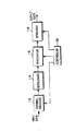
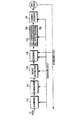
図1は既存の高速パケットデータ伝送のための送信器の一例を示したもので、前記図1のチャネル符号化部112を制御することにより、多様な適応変調/コード方式と複合再伝送方式を具現することができる。
前記図1を参照すると、チャネル符号化部112は符号器と穿孔部に構成される。前記チャネル符号化部112の入力端にデータ伝送速度に適合な所定のデータが入力されると、伝送エラー率を低減するために前記符号器で符号化を進行する。また、既に前記制御部120で決定された符号率及び複合再伝送形式に応じて前記符号器の出力を穿孔部で穿孔してチャネルインタリーバ114に出力させる。次世代移動通信システムでは高速のマルチメディアデータの信頼性ある伝送のため、より強力なチャネルコーディング技法が要求されるので、前記図1のチャネル符号化部を具現する一例として、母コード率が1/6であるターボ符号器200及び穿孔部216を図2で示した。前記ターボ符号器200を利用するチャネルコーディング技法は、低い信号対雑音比でもビットエラー率(BER)観点でシャノン限界(Shannon limit)に一番近接する性能を示すことに知らせている。前記ターボ符号器200によるチャネルコーディング技法は、現在3GPPと3GPP2で進行中であるHSDPA及び1xEV−DV標準化にも採択されている方式である。前記図2のターボ符号器200の出力は、システマテック(systematic)ビットとパリティ(parity)ビットに区別されることができる。前記システマテックビットは伝送しようとする情報ビットその自体を意味し、前記パリティビットは受信器で復号時、伝送中に発生されたエラーを補正するために使用される信号である。前記穿孔部216は前記符号器200の出力中、前記システマテックビット、またはパリティビットを選別的に穿孔、出力させることにより、決定された符号率を満足させるようになる。
【0011】
前記図2を参照すると、入力された一つの送信フレームはそのままシステマテックビットフレーム(X)に出力されると同時に、第1チャネル符号器210に入力され所定の符号化を通じて二つの相異なるパリティビットフレーム(Y1、Y2)に出力される。また、前記送信フレームは内部インタリーバ212に入力され、インタリービングされた送信フレームはそのままインタリービングされたシステマテックビットフレーム(X')に出力される。これと同時に、前記インタリービングされた送信フレームは第2チャネル符号器214に入力され、所定の符号化を通じて二つの相異なるパリティビットフレーム(Z1、Z2)に出力される。前記システマテックビットフレーム(X、X')及び前記パリティビットフレーム(Y1、Y2、Z1、Z2)はそれぞれ1、2、...、Nの伝送単位に穿孔部216に入力される。前記穿孔部216は前記図1の制御部120から制御信号を受信して穿孔パターン(Puncturing Pattern)を決定し、前記決定された穿孔パターンを利用して前記システマテックビットフレーム(X)、前記インタリービングされたシステマテックビットフレーム(X')及び前記四つの相異なるパリティビットフレーム(Y1、Y2、Z1、Z2)を穿孔して所望するシステマテックビット(S)とパリティビット(P)のみを出力する。
【0012】
一方、上述したように、前記穿孔器216で符号化ビットを穿孔する形態は、前記符号率と前記複合再伝送方式によって変化するようになる。即ち、CCの場合、所定の符号率に応じてシステマテックビットとパリティビットの固定された組み合わせを有するように、前記符号化ビットを穿孔することにより伝送時ごとに同一のパケットを送ることができる。FIR及びPIRの場合、初期伝送時は所定の符号率に応じて前記符号化ビットをシステマテックビットとパリティビットの組み合わせに穿孔し、再伝送ごとに多様なパリティビットの組み合わせに穿孔することにより、全体的に符号化率を低くする効果を有することができる。例えば、符号率が1/2である環境で、CCの場合、前記穿孔器216は前記穿孔パターンとして[X Y1 Y2 X' Z1 Z2]の符号化ビット順序に[110000]を固定使用することにより、初期伝送及び再伝送時、一つの入力ビットに対して同一のビットであるXとY1を続けて出力させることができる。IRの場合、前記穿孔器216は初期伝送時と再伝送時、前記穿孔パターンにそれぞれ[110000;100001]と[001001;010010]を使用することにより、二つの入力ビットに対して初期伝送時には[X1 Y11 X2 Z21]の順序に出力され、再伝送時には[Y21 Z21 Y12 Z12]の順序に出力される。一方、図示しないが、3GPP2で採択している符号率R=1/3ターボコードを使用する場合には、前記図2で示している第1チャネル符号器210と穿孔部216に容易に具現することができる。
【0013】
前記図1に基づいて前記適応変調/コード方式と複合再伝送方式を具現したシステムのパケットデータの伝送過程を説明すると、新しいパケットの伝送前に、送信端の制御部120では受信端から伝送された下向チャネル状態に対する情報に基づいて適切な変調方式と伝送データの符号率を決定する。そして、前記決定した変調方式と符号率をチャネル符号化部112、変調部116及び周波数拡散部118に知らせるようになる。前記決定された変調方式及び符号率に応じて物理階層でのデータ伝送速度が決定される。前記チャネル符号化部112は前記決定された変調方式及び符号率により符号化を進行した後、所定の穿孔パターンによるビット穿孔を遂行する。前記チャネル符号化部112で出力される符号化ビットは、チャネルインタリーバ114に入力されインタリービングが進行される。
【0014】
前記インタリービング技術は入力ビットの順序を相異なるようにすることにより、フェーディング環境でデータシンボルの損傷が一所に集中されなく、多所に分散されるようにして、バーストエラー(burst error)が発生しないようにする技術である。説明の便宜上、前記チャネルインタリーバ114の大きさは、全体符号化ビットの数より大きいか、同一であるものとする。変調部116に入力された前記インタリービングされた符号化ビットは、前記決定された変調方式によりシンボルマッピングされ変調シンボルに出力される。この時、Mを変調方式とする場合、一つのシンボルを形成するビット数はlog2Mになる。周波数拡散部118は前記決定されたデータ伝送速度により前記変調シンボルを伝送するための多重ウォルシュ(Walsh)コードを割り当て、前記割り当てられたウォルシュ(Walsh)コードに前記変調シンボルを拡散する。通常的に固定チップ伝送率と固定スプレディングファクタ(SF)を使用する場合、一つのウォルシュ(Walsh)コードに伝送されるシンボル伝送率は一定になる。従って、定められたデータ伝送速度を使用するためには、多重ウォルシュ(Walsh)コードの使用が要求される。一例に3.84Mcpsのチップ伝送率と16チップ/シンボルのSFを使用するシステムで、16QAMとチャネル符号率3/4を使用する場合、1個のウォルシュ(Walsh)コードに提供することができる伝送速度は1.08Mbpsになる。従って、10個のウォルシュ(Walsh)コードを利用する場合、最大10.8Mbpsの速度にデータを伝送することができる。
【0015】
前記図1の高速パケット伝送システムの送信器構造では、初期伝送時に適応変調/コード方式により決定された変調方式及び符号率を再伝送時にも変化なし適用する状況を仮定した。しかし、上述したように高速データ伝送チャネルは、セル内の通話端末数の変化及びドップラー変化などにより、複合再伝送期間の間にも十分にその状況が変化することができる。従って、初期伝送時に使用した変調/コード方式を維持することは、結果的にシステムの性能を低下させる要因になることができる。
【0016】
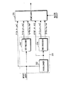
このような理由のため、現在進行されているHSDPA及び1xEV−DVの標準化では、再伝送期間中にも変調/コード方式を変化させることができる方法を考慮している。一例に複合再伝送方式にCCを使用するシステムで再伝送変調方式が変化した場合、送信端では初期伝送されたデータパケットの一部分、または全体を再伝送し、受信端では再伝送された部分的パケットを初期伝送された全体パケットと部分的にコンバインする。これは結果的に復号器の全体ビットエラー率を低くする。前記送信器の構造は図3で示しており、前記受信器の構造は図4でそれぞれ示している。
【0017】
前記図3の送信器構造から分かるように、上述した方式は、部分チェース符号器316を前記図1の送信器構造に添加したものである。前記図3を参照して送信手順を説明すると、チャネル符号化部312で所定の符号率と複合再伝送方式により出力された符号化ビットは、インタリーバ314でインタリービングされた後、前記部分チェース符号器316に出力される。前記部分チェース符号器316は制御部322から初期伝送、現在の変調方式及び使用するウォルシュ(Walsh)コードの数に対する情報を受信し、前記インタリービングされた符号化ビット中、再伝送時に伝送するデータの量を調節する。変調部318は前記部分チェース符号器316で出力された符号化ビットに対して所定の変調方式に基づいてシンボルマッピングを遂行した後、拡散部320に出力させる。前記拡散部320は使用可能なウォルシュ(Walsh)コード中で必要な数のウォルシュ(Walsh)コードを割り当てた後、各ウォルシュ(Walsh)コードに周波数拡散させる。この時、再伝送時のチャネル符号率は初期伝送時の符号率と同一であり、再伝送時に使用可能なウォルシュ(Walsh)コードの数は、初期伝送時に使用したウォルシュ(Walsh)コードの数と異なることもできる。しかし、本発明では初期伝送時と再伝送時に同じ数のウォルシュ(Walsh)コードを使用すると仮定する。従って、初期伝送時のシンボル伝送率と再伝送時のシンボル伝送率は同一になって、結局、再伝送される符号化ビットを調節すべきである。
【0018】
図4は前記図3の送信器構造に相応した受信器構造を示した図である。既存システムの受信器に前記図3の部分チェース符号器316に対応する部分チェースコンバイナ416を追加した。逆拡散部412は送信器と同一のウォルシュ(Walsh)コードを使用して前記送信器からのデータシンボルを復旧した後、復調部414に出力させる。前記復調部414は前記送信器で使用された変調方式に相応する復調方式に、前記逆拡散部412からのデータシンボルに対して復調を遂行して、これに対するLLR(Log Likelihood Ratio)値を部分チェースコンバイナ416に出力する。前記LLR値は復調された各符号化ビットに対してソフトディスィジョン(soft decision)を遂行した値を意味する。前記部分チェースコンバイナ416は既存の受信器構造のソフトコンバイナに代わるものである。これは、初期伝送と再伝送時の変調方式が異なる場合、再伝送されたデータの量が初期伝送されたデータの量と異なるので、パケットコンバインは部分的のみに遂行されるからである。前記部分チェースコンバイナ416は、再伝送時に高次変調方式が使用されると、全体パケットに対してコンバインを遂行する。しかし、再伝送時に低次変調方式が使用されると、部分的コンバインを遂行する。デインタリーバ418は前記部分チェースコンバイナ416からのデータを本来の順序通り再配置した後、チャネル復号化部420に出力する。前記チャネル復号化部420は前記再配置された符号化ビットを情報ビットに復号する。図4には図示なかったが、前記受信器は前記情報ビットに対してCRC(Cyclic Redundancy Check)検査を遂行した後、前記CRC検査結果に応じて確認信号として、ACK(Acknowledge)、またはNACK(Negative Acknowledge)信号を送信器に伝送して、新しいパケットの伝送、または誤りが発見された伝送パケットの再伝送を要求するようになる。
【0019】
図5Aと図5Cでは初期伝送及び再伝送時の変調方式の変化に応じて、部分チェース符号器316を通じて伝送されるパケット大きさ変化の一例を示した。
先ず、変調率が初期伝送より再伝送時に低い場合、部分チェース符号器316から出力される符号化ビットが、初期伝送に比べて再伝送時に減少することを前記図5Aから分かることができる。前記図5Aでは初期伝送時に16QAMを使用し、再伝送時にはQPSKを使用する場合を仮定した。従って、再伝送時には初期伝送時に伝送されたデータパケットの1/2のみを伝送することができる。
【0020】
次に、変調率が初期伝送より再伝送時に高い場合、部分チェース符号器316から出力される符号化ビットが初期伝送に比べて再伝送時に増加することを前記図5Cから分かることができる。前記図5Cでは初期伝送時にQPSKを使用し、再伝送時には16QAMを使用する場合を仮定した。従って、再伝送時には初期伝送時に伝送されたデータパケットを二度反復して伝送することができる。
【0021】
図5Bと図5Dでは初期伝送及び再伝送時の変調方式の変化による受信パケットが部分チェースコンバイナ416を通じてコンバインされる一例を示した。
先ず、変調率が初期伝送より再伝送時に低い場合、即ち、初期伝送時に16QAMを使用し、再伝送時にQPSKを使用すると、再伝送を通じて初期伝送されたパケットの1/2のみが追加に受信される。これは前記図5Bで詳細に示している。従って、前記部分チェースコンバイナ416は前記初期伝送を通じて受信したパケットと前記再伝送を通じて受信された1/2のパケットをコンバインすることにより、受信信号の信頼度を向上させることができる。
【0022】
次に、変調率が初期伝送より再伝送時に高い場合、即ち初期伝送時にQPSKを使用し、再伝送時に16QAMを使用すると、再伝送を通じて初期伝送されたパケットが追加に二回受信される。従って、前記部分チェースコンバイナ416は前記初期伝送及び再伝送を通じて3回受信した同一のパケットをコンバインすることにより、受信信号の信頼度を向上させることができる。
【0023】
複合再伝送方式にCCを使用する高速パケット伝送システムで、前記図3と前記図4で示した部分チェース符号器316及び部分チェースコンバイナ416を使用することにより、再伝送時にも変調方式を変えてチャネル変化にもう能動的に対処できるようにした。これはシステムの性能を向上させることができる利点がある。しかし、全体伝送パケットに対する部分的コンバインは、ビットエラー率を低減することはできるが、フレームエラー率を低減するにはその効果があまりない。これは、前記図3のチャネルインタリーバ314の出力は、前記チャネル符号化部312のシステマテックビットとパリティビットの無作為の組み合わせになるからである。即ち、再伝送時に初期伝送より小さい大きさのパケットを伝送する場合には、全体情報ビットに対してコンバインが遂行できないので、コンバイン効果はビット単位にランダムに発生する。特に、CCを使用するシステムで再伝送時に初期伝送時より小さいパケットを伝送すべきである場合にも、前記ターボコードのシステマテックビットとパリティビットの組み合わせに出力される特徴を利用して情報ビットに対して全体的に補償することにより、フレームエラー率を画期的に低減することができる新しい方法が提示されるべきである。
【0024】
【発明が解決しようとする課題】
上述した問題点を解決するための本発明の目的は、無線通信システムの性能を向上させるためのデータ送/受信装置及び方法を提供することにある。
本発明の他の目的は、無線通信システムでより高い受信確率によりデータビットを受信することができるデータ送/受信装置及び方法を提供することにある。
本発明のさらに他の目的は、ターボコードの出力でシステマテックビットとパリティビットに独立的に適用されたチャネルインタリーバ及びこれに相応する受信端でのデインタリーバを使用してより効率的な高速データ送/受信装置及び方法を提供することにある。
本発明のさらに他の目的は、ターボコードの出力でシステマテックビットとパリティビットに独立的に適用されたチャネルインタリーバと複合再伝送技法(HARQ)中、CC(Chase Combining)を連動してより効率的な高速データ送/受信装置及び方法を提供することにある。
本発明のさらに他の目的は、適応変調及びコーディング技法が要求される高速無線通信システムの送信端で、再伝送時にチャネル符号化率は初期伝送と同一に維持しながら、変調方式のみを適応的に変化させることにより、システムの性能利得を得ることができる装置及び方法を提供することにある。
本発明のさらに他の目的は、適応変調方式が適用された高速無線通信システムの送信端で、要求される変調方式に応じてシステマテックビットとパリティビットに分けられたデータパケット中の一つを選択的に再伝送することにより、システムの性能利得を得ることができる制御装置及び方法を提供することにある。
本発明のさらに他の目的は、高速無線通信システムの送信端で要求される変調方式により選択的に再伝送されたデータパケットを受信端で初期伝送されたデータパケットと選択的にソフトコンバインすることにより、性能利得を得ることができるようにする制御装置及び方法を提供することにある。
【0025】
【課題を解決するための手段】
上述したような目的を達成するための第1見地において、本発明は与えられた符号率を有するターボ符号器を含み、複数の変調方式中のいずれか一つを使用してデータを前記ターボ符号器により符号化したシステマテックビットとパリティビットを初期伝送する符号分割多重接続移動通信システムの送信器で受信器から再伝送要請により前記データの再伝送を遂行する方法において、前記再伝送要請時に前記送信器と前記受信器間に使用する変調方式を決定する過程と、前記所定符号率により符号化された符号化ビットをシステマテックビットとパリティビットに分配する過程と、前記決定された変調方式が前記初期伝送時に使用された変調方式と異なる場合、前記初期伝送時の前記システマテックビットと前記パリティビット中、前記決定した変調方式により伝送可能な符号化ビットを前記決定された変調方式に基づいた変調シンボルに変換して伝送する過程と、を含むことを特徴とする。
【0026】
上述したような目的を達成するための第2見地において、本発明は与えられた符号率を有するターボ符号器を含み、複数の変調方式中のいずれか一つを使用してデータを前記ターボ符号器により符号化したシステマテックビットとパリティビットを初期伝送する符号分割多重接続移動通信システムの送信器で受信器から再伝送要請により前記データの再伝送を遂行する装置において、前記再伝送要請時に前記送信器と前記受信器間に使用する変調方式を決定する制御部と、前記所定符号率により符号化された符号化ビットをシステマテックビットとパリティビットに分配する分配部と、前記決定された変調方式が前記初期伝送時に使用された変調方式と異なる場合、前記初期伝送時の前記システマテックビットと前記パリティビット中、前記決定した変調方式により伝送可能な符号化ビットを出力する選択部と、前記伝送可能な符号化ビットを前記決定された変調方式に基づいた変調シンボルに変換して伝送する変調部と、を含むことを特徴とする。
【0027】
上述したような目的を達成するための第3見地において、本発明は与えられた符号率を有するターボ符号器を含み、複数の変調方式中のいずれか一つを使用してデータを前記ターボ符号器により符号化したシステマテックビットとパリティビットを所定変調方式により変調シンボルとして初期伝送する符号分割多重接続移動通信システムの送信器から前記初期伝送時の変調方式と異なる変調方式により再伝送される変調シンボルを受信する方法において、前記変調シンボルを前記再伝送時に使用された変調方式に対応する復調方式に基づいて符号化ビットに出力する過程と、前記符号化ビットを前記システマテックビットに構成されたシステマテックパケットと前記パリティビットに構成されたパリティパケットに分離する過程と、前記システマテックパケットを以前に受信したシステマテックパケットとコンバインし、前記パリティパケットを以前に受信したパリティパケットとコンバインする過程と、前記コンバインされたシステマテックパケットと前記コンバインされたパリティパケットから情報ビットを復号する過程と、を含むことを特徴とする。
【0028】
上述したような目的を達成するための第4見地において、本発明は与えられた符号率を有するターボ符号器を含み、複数の変調方式中のいずれか一つを使用してデータを前記ターボ符号器により符号化したシステマテックビットとパリティビットを所定変調方式により変調シンボルとして初期伝送する符号分割多重接続移動通信システムの送信器から前記初期伝送時の変調方式と異なる変調方式により再伝送される変調シンボルを受信する装置において、前記変調シンボルを前記再伝送時に使用された変調方式に対応する復調方式に基づいて符号化ビットに出力する復調部と、前記符号化ビットを前記システマテックビットに構成されたシステマテックパケットと前記パリティビットに構成されたパリティパケットに分離するパケット分配部と、前記システマテックパケットを以前に受信したシステマテックパケットとコンバインし、前記パリティパケットを以前に受信したパリティパケットとコンバインするコンバイナと、前記コンバインされたシステマテックパケットと前記コンバインされたパリティパケットから情報ビットを復号する復号化部と、を含むことを特徴とする。
【0029】
【発明の実施形態】
以下、本発明の望ましい実施形態について添付図を参照しつつ詳細に説明する。下記の発明において、本発明の要旨のみを明瞭にする目的で、関連した公知機能又は構成に関する具体的な説明は省略する。先ず、後述される本発明の実施形態に従う詳細な説明では、チャネル符号化部の符号率に1/2と3/4を支援し、QPSK、8PSK、16QAM、64QAMの変調方式中、初期伝送を16QAM方式にし、再伝送時に他の変調方式に変わる場合に対する実施形態を提案する。また後述される詳細な説明では複合再伝送形式中、チェースコンバイン(Chase Combining)を使用する場合のみに対して説明する。
【0030】
以下、本発明の実施形態を添付された図を参照して説明すると、次のようである。
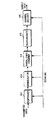
図6は本発明の実施形態に従う符号分割多重接続移動通信システムの送信器構成を示している図である。
前記図6を参照すると、制御部(AMCS)626は本発明の実施形態に従う送信器の全般的な動作を制御する。特に、前記制御部626は上位階層(図示せず)から提供される信号情報(Signaling Information)に基づいて伝送するデータの変調方式と符号率を決定する。前記制御部626は前記決定された符号率と変調方式に基づいて周波数拡散部624で要求される直交符号(一例としてウォルシュコード)の数を決定する。前記変調方式と符号率は前記上位階層により決定され、前記信号情報に含まれて前記制御部626に提供されることもできる。一方、前記変調方式を決定する代表的な方法は、初期伝送時と再伝送時ごとにデータを伝送する下向トラヒックチャネルの状態に対応して決定する方法である。従って、前記制御部626は初期伝送時と再伝送ごとに相異なる変調方式を決定することができる。前記初期伝送は受信器からの確認信号としてACKが受信される時に遂行され、前記再伝送は前記受信器からの確認信号としてNACKが受信される時に遂行される。前記下向トラヒックチャネルの状態は受信器で伝送された現在の下向トラヒックチャネルに対する情報により分かることができる。前記決定された変調方式情報は後述されるパケット選択部620と変調部622に提供される。また、前記決定された符号率情報はチャネル符号化部(Channel Encoder)612に提供される。
【0031】
前記チャネル符号化部612は所定コードと前記制御部626から提供される符号率を利用して入力されるデータを符号化して符号化ビットを出力する。前記入力されるデータには受信側でのエラー確認のためのCRCが追加される。前記所定コードは前記入力されるデータを符号化することにより伝送しようとするビットと前記ビットのエラー制御ビットに構成された符号化ビットを出力するようにするコードを通称する。例えば、前記所定コードにターボコードを使用する場合、前記伝送しようとするビットはシステマテックビットになり、前記エラー制御ビットはパリティビットになる。一方、前記チャネル符号化部612は符号器と穿孔器にその機能を分けることができる。前記符号器は所定符号率により前記入力されるデータを符号化し、前記穿孔器は前記所定符号率に応じて前記符号器から出力されるシステマテックビットとパリティビットの比率を決定する。例えば、前記所定符号率が対称として1/2である場合、前記チャネル符号化部612は1ビットを受信して一つのシステマテックビットと一つのパリティビットを出力する。しかし、前記所定符号率が非対称として3/4である場合、前記チャネル符号化部612は3ビットを受信して三つのシステマテックビットと一つのパリティビットを出力する。後述される本発明の実施形態に従う動作説明では、前記二つの相異なる符号率1/2、3/4を相異なる実施形態として説明する。
【0032】
分配部(Distributor)614は前記チャネル符号化部612から入力された前記システマテックビットと前記パリティビットを複数のインタリーバに分配する。前記複数のインタリーバに二つのインタリーバ616、618が存在する場合、前記分配器614は前記システマテックビットと前記パリティビットを二つのビットグループに分配する。例えば、前記チャネル符号化部612からの前記システマテックビットは第1インタリーバ616に分配し、残りのパリティビットは第2インタリーバ618に分配する。従って、1/2のように対称符号率を使用する場合には、同一のビット数のシステマテックビットとパリティビットが前記チャネル符号化部612から出力されるので、前記第1インタリーバ616と前記第2インタリーバ618には同一の量の符号化ビットが満たされる。しかし、3/4のように非対称符号率を使用する場合には、前記第1インタリーバ616に満たされるシステマテックビットが前記第2インタリーバ618に満たされるパリティビットに比べて3倍が多い。
【0033】
前記第1インタリーバ616は前記分配部614からのシステマテックビットをインタリービングして出力し、前記第2インタリーバ618は前記分配部614からのパリティビットをインタリービングして出力する。前記図6では前記第1インタリーバ616と前記第2インタリーバ618がハードウェアにより区分され示されている。しかし、前記第1インタリーバ616と前記第2インタリーバ618を単純に論理的に区分することもできる。前記論理的区分は一つのメモリのみを使用し、前記システマテックビットを貯蔵するメモリ領域と前記パリティビットを貯蔵するメモリ領域を区分して使用することを意味する。
【0034】
パケット選択部620は前記制御部626から変調方式情報を受信し、前記変調方式により通常的に伝送可能なデータ量を決定する。前記伝送可能なデータ量が決定されると、前記パケット選択部620は前記第1インタリーバ616と前記第2インタリーバ618から提供されるシステマテックビットとパリティビットに区分された所定パケット中の一つを選択して出力する。前記所定パケットは前記システマテックビットのみに構成されたシステマテックパケットと前記パリティビットのみに構成されたパリティパケットに区分することができる。通常的に送信器ではデータをTTI(Time To Interleaving)単位に伝送する。前記TTIは所定時点で符号化ビットの伝送をスタートして伝送が完了されるまで所要される時間を意味する。前記TTIはスロット(slot)単位を有する。例えば、前記TTIは3個のスロットに構成されることができる。従って、前記所定パケットは前記TTIの間に伝送される符号化ビットを意味する。
【0035】
一方、上述したように、前記パケット選択部620には前記制御部626から初期伝送時と再伝送ごとに相異なる変調方式が提供されることができる。従って、前記パケット選択部620は変調方式が変更されるごとに変更された変調方式に対応して伝送するパケットを適切に選択すべきである。例えば、前記パケット選択部620は初期伝送時には前記TTI単位のシステマテックパケットとパリティパケットを選択して出力する。しかし、再伝送時に変調方式が変更される場合、前記パケット選択部620は前記初期伝送時に伝送したパケットをそのまま伝送できない。従って、前記パケット選択部620は前記初期伝送されたTTI単位のシステマテックパケットと前記パリティパケットを所定大きさを有する複数のサブパケットに分離し、前記決定されたデータ量により前記複数のサブパケットを選択出力する。前記選択において、前記決定されたデータ量が初期伝送されたデータ量より少ない場合には、前記複数のサブパケット中の一部を選択する。しかし、前記決定されたデータ量が前記初期伝送されたデータ量より多い場合には、前記複数のサブパケットと前記複数のサブパケット中の一部を重複して選択する。従って、前記サブパケットは変化する変調方式に対応して伝送しようとするデータ量を容易に可変できるようにする大きさを有するべきである。また、前記パケット選択部620は前記データ量に応じてパケットを選択することにおいて、伝送しようとする符号化ビットの重要度と共に再伝送回数を勘案すべきである。即ち、前記初期に伝送されたシステマテックパケットとパリティパケット中の一部を伝送する場合には、実質的な情報ビットということができるシステマテックパケットを優先的に選択する。ここで、前記システマテックパケットは初期伝送時にTTI単位に伝送されたシステマテックビットに構成されたパケットを意味し、前記パリティパケットは初期伝送時にTTI単位に伝送されたパリティビットに構成されたパケットを意味する。また、前記初期に伝送されたシステマテックパケットとパリティパケット中の一部を反復して伝送する場合には、システマテックパケットを優先的に選択する。しかし、再伝送ごとにシステマテックパケットのみを伝送する代わり、伝送されない他のパケットを伝送するのがシステムの性能を向上させることができる。このため、前記パケット選択部620は前記再伝送回数を使用することができる。例えば、前記再伝送回数が奇数番目である場合には、システマテックパケットを優先的に伝送し、前記再伝送回数が偶数番目である場合には、パリティパケットを優先的に伝送する。従って、前記パケット選択部620は再伝送時に前記システマテックビットのみを出力させるか、前記パリティビットのみを出力させるか、前記システマテックビットとパリティビットの組み合わせの形態に出力させるようになる。前記パケット選択部620が多様な変調方式により符号化ビットを選択するパターンの例は図8Aと図8で示しており、これに対する詳細な説明は後述する。
【0036】
変調部(Modulator)622は前記制御部626から提供される変調方式に応じて前記パケット選択部620により選択されたパケットの符号化ビットを変調して出力する。前記符号化ビットの変調は所定のシンボルマッピング方式に基づいて前記符号化ビットを伝送するシンボルにマッピングさせる動作により遂行される。前記伝送するシンボルそれぞれのマッピングパターンは前記制御部626から提供される変調方式により決定される。例えば、前記制御部626から提供される変調方式が16QAMである場合、シンボルそれぞれが{H、H、L、L}のシンボルパターンを有するようになり、64QAMである場合にはシンボルそれぞれが{H、H、M、M、L、L}のシンボルパターンを有するようになる。前記シンボルパターンにおいて、“H”は高い信頼度を有するビット位置を意味し、“M”は中間信頼度を有するビット位置を意味し、“L”は低い信頼度を有するビット位置を意味する。一方、前記制御部626からの変調方式が8PSKの場合には、シンボルそれぞれが3個のビット位置に構成されたシンボルパターンを有するようになり、QPSKの場合にはシンボルそれぞれが2個のビット位置に構成されたシンボルパターンを有するようになる。
【0037】
拡散部(Spreader)624は前記変調部622から出力されるシンボルそれぞれに対して前記制御部626から割り当てられた直交符号(一例としてウォルシュコード)に周波数拡散させた後、受信器に伝送する。この時、前記直交符号の数は前記制御部626により決定されたチャネル符号率と変調方式に応じて決定され、前記決定された数の直交符号それぞれは前記変調部622から出力されるシンボルそれぞれに対して割り当てられる。
【0038】
図10は上述した本発明の実施形態に従う送信器の動作順序を示している処理流れ図である。前記図10で示しているように、本発明の実施形態に従う送信器の動作は、伝送しようとするデータに対して符号化を遂行し、前記符号化による符号化ビットを分配する過程と、前記分配された符号化ビットそれぞれに対してインタリービングを遂行した後、初期伝送及び再伝送ごとに変更可能な変調方式により前記インタリービングされた符号化ビット中に伝送する符号化ビットを選択し、前記変調方式により変調する過程と、を含む。
【0039】
図7は前記図6で示している送信器に対応した本発明の実施形態に従う受信器構造を示している図である。
前記図7を参照すると、送信器から多重直交符号により周波数拡散され伝送されたデータシンボル(Tx Data)は下向トラヒックチャネルを通じて受信される。逆拡散部712は前記受信されたデータシンボルを前記送信器で使用された直交符号により逆拡散し、前記逆拡散により得られる伝送シンボルを多重して直列に出力する。
【0040】
復調部714は前記送信器で使用した変調方式に相応した復調方式により前記逆拡散部712から出力される伝送シンボルに対して復調を遂行して復調シンボルを出力する。前記復調シンボルは前記送信器でのパケット選択部620からの出力符号化ビットに対応し、無線チャネルでの雑音などによりLLR値を有する。
【0041】
パケット分配部716は前記復調部714から出力される復調シンボルのLLR値を入力にし、前記復調シンボルを前記送信器で使用された変調方式によりシステマテックパケットとパリティパケットに分離して出力する。前記システマテックパケットはシステマテックビットに構成されたパケットを意味し、前記パリティパケットはパリティビットに構成されたパケットを意味する。前記パケット分配部716は前記復調シンボルを分配するために、初期伝送変調方式と現在の変調方式及び再伝送回数などの情報を利用して、前記復調シンボルの特性を判断する。前記復調シンボルの特性は、前記復調シンボルがシステマテックビットに構成されたシステマテックパケットであるか、パリティビットに構成されたパリティパケットであるか、またはシステマテックビットとパリティビットの組み合わせであるかを示す。前記パケット分配部716は前記判断された特性により前記復調シンボルをコンバイナ718に分配する。
【0042】
コンバイナ718は内部的にシステマテックパケットに対する第1バッファとパリティパケットに対する第2バッファに構成される。従って、前記コンバイナ718は前記第1バッファを利用して予め貯蔵されていた初期伝送時のシステマテックパケットを構成するシステマテックビット、再伝送ごとのシステマテックパケットを構成するシステマテックビット、及び新しい提供されたシステマテックパケットを構成するシステマテックビットをビット単位へのコンバインを遂行する。また、前記コンバイナ718は前記第2バッファを利用して予め貯蔵されていた初期伝送時のパリティパケットを構成するパリティビット、再伝送ごとのパリティパケットを構成するパリティビット、及び新しい提供されたパリティパケットを構成するパリティビットをビット単位へのコンバインを遂行する。この時、前記コンバイナ718は前記パケット分配部716により分配されたパケットと同一の特性を有する前記システマテックパケット、または前記パリティパケットに対して独立的にコンバインを遂行するようになる。
【0043】
例えば、再伝送時に前記送信器からシステマテックパケットのみが伝送されたら、前記分配部716はこれを前記コンバイナ718の前記第1バッファに提供し、前記コンバイナ718は初期伝送により前記第1バッファに貯蔵されていたシステマテックパケットと前記再伝送されたシステマテックパケットをコンバインする。この時、前記第2バッファに貯蔵されていたパリティパケットに対するコンバインは遂行されない。一方、前記再伝送時に前記送信器からパリティパケットのみが伝送されたら、前記パケット分配部716はこれを前記コンバイナ718の前記第2バッファに提供し、前記コンバイナ718は初期伝送により前記第2バッファに貯蔵されていたパリティパケットと前記再伝送されたパリティパケットをコンバインする。この時、前記第1バッファに貯蔵されていたシステマテックパケットに対するコンバインは遂行されない。
【0044】
デインタリーバ710は前記図6で示している送信器のインタリーバ610に相応する構成として、二つの独立的なデインタリーバに構成されている。前記二つのデインタリーバ中、第1デインタリーバ720は前記コンバイナ718の第1バッファから提供されるコンバインされたシステマテックパケットを構成するシステマテックビットに対してデインタリービング動作を遂行する。また、前記二つのデインタリーバ中、第2デインタリーバ722は前記コンバイナ718の第2バッファから提供されるコンバインされたパリティパケットを構成するパリティビットに対してデインタリービング動作を遂行する。この時、前記デインタリーバ710で使用されるデインタリービングパターンは、前記図6のインタリーバ610で使用されたインタリービングパターンの逆順であるので、前記デインタリーバ710は前記インタリービングパターンを予め知っているべきである。
【0045】
チャネル復号化部724は機能上、復号器とCRC検査器に区分することができる。前記復号器は前記デインタリーバ710からのシステマテックビットとパリティビットに構成された符号化ビットを受信し、前記受信された符号化ビットを所定復号化方式により復号化して所望する受信ビットを出力する。この時、前記所定復号化方式にはシステマテックビットとパリティビットを受信して、前記システマテックビットを復号する方式を使用し、前記復号化方式は前記送信器の符号化方式に対応して決定される。前記復号器から復号された後に出力される受信ビットは送信器でデータ伝送時に追加したCRCビットを含む。従って、前記CRC検査器は前記受信ビットに含まれたCRCビットを利用して前記受信ビットを検査してエラー発生可否を判断する。前記受信ビットにエラーが発生されなかったと判断されると、前記受信ビットを出力し、前記受信ビットの受信を確認する応答信号としてACKを前記送信器に伝送する。しかし、前記受信ビットにエラーが発生したと判断されると、応答信号として前記受信ビットの再伝送を要求するNACKを前記送信器に伝送する。
【0046】
この時、確認信号としてACKが伝送されるか、NACKが伝送されるかによって、前記コンバイナ718の第1バッファと第2バッファは初期化されるか、現在状態を維持するようになる。即ち、ACKが伝送される場合、新しいパケットを受信すべきであるので、前記第1バッファと第2バッファは初期化され、NACKが伝送される場合には、前記第1バッファと第2バッファの現在状態を維持して、再伝送されるパケットとのコンバインを準備する。
【0047】
一方、上述した構成から分かるように、受信器では復調及び復号などの動作のため、前記図6の送信器で使用された符号率、変調方式、直交符号及び再伝送回数などに対する情報を予め知っているべきである。即ち、前記送信器の動作に対応して前記受信器が動作できるように、上述した情報は前記受信器の逆拡散部712、復調部714、分配部716、コンバイナ718及び復号器724などに予め提供されるべきである。従って、上述した情報は下向制御チャネルを通じて前記送信器から前記受信器に提供される。
【0048】
図11は上述した本発明の実施形態に従う受信器の動作順序を示している処理流れ図である。前記図11で示しているように、本発明の実施形態に従う受信器での動作は、受信したデータを復調して送信器で使用された変調方式により復調シンボルを分配する過程と、前記分配した復調シンボルのそれぞれを以前に受信した復調シンボルとコンバインした後、デインタリービングを通じて出力される符号化ビットをチャネル復号化する過程と、を含む。
【0049】
先ず、本発明の実施形態による動作を詳細に説明する前に、本発明で提案しようとする実施形態に対して簡単に説明すると、次のようである。
本発明で提案する一番目の実施形態は、1/2の符号率と複合再伝送方式中のCCを支援する符号分割多重接続移動通信システムで、初期伝送と再伝送時、相異なる変調方式を支援する送信器及び受信器を提案する。この時、初期伝送時には16QAMを変調方式にし、再伝送時には64QAM、8PSK及びQPSKを変調方式にする。また、細部的には送信器で再伝送時に変化された変調方式に応じて伝送する符号化ビットを選択し、受信器でこれを効果的にコンバインする方法を提案する。
【0050】
本発明で提案する二番目の実施形態は、3/4の符号率と複合再伝送方式中のCCを支援する符号分割多重接続移動通信システムで、初期伝送と再伝送時、相異なる変調方式を支援する送信器及び受信器を提案する。この時にも、初期伝送時には16QAMを変調方式にし、再伝送時には64QAM、8PSK及びQPSKを変調方式にする。また、細部的には送信器で再伝送時に変化された変調方式に応じて伝送する符号化ビットを選択し、受信器でこれを効果的にコンバインする方法を提案する。
【0051】
1.第1実施形態(符号率が1/2である場合)
以下、上述した図を参照して本発明の第1実施形態に従う動作を詳細に説明する。先ず、後述する本発明の第1実施形態は1/2を符号率にし、CCを複合再伝送方式に使用する。また、初期伝送時の変調方式は16QAMに仮定し、再伝送時にも初期伝送時と同じ数の直交符号を使用すると仮定する。
【0052】
1.1 送信動作
1.1.1 チャネル符号化(図10の1010段階)
CRCが追加された伝送データはチャネル符号化器612に入力され、所定コードと制御部626から提供される1/2の符号率により符号化され、符号化ビットが直列に出力される。前記符号化ビットは伝送しようとする伝送データに該当するシステマテックビットと、前記伝送しようとする伝送データのエラー制御のためのパリティビットに出力される。この時、前記チャネル符号化器612は符号率が1/2として対称であるので、前記システマテックビットと前記パリティビットを同一の比率に出力する。一方、前記システマテックビットと前記パリティビットは前記チャネル符号化器612の内部に設けられた穿孔部の一定穿孔パターンによって穿孔が遂行される。複合再伝送方式がCCの場合、初期伝送及び再伝送時、同一の穿孔パターンが使用されるので、前記チャネル符号化器612は伝送時ごとに同一のデータビットストリームを出力させる。即ち、初期伝送及び再伝送ごとに同一のシステマテックビットとパリティビットを出力するようになる。通常的に、トランスポートチャネルマルチプレクシングがあるか、前記符号化器612からの符号化ビットが無線上で伝送されるべきであるビットと一致しない場合には、前記符号化ビットに対する反復(Repetition)、または穿孔(Puncturing)動作を遂行する構成が要求される。前記反復及び穿孔動作を“レートマッチング”という。本発明では前記チャネル符号化器612が前記レートマッチングを遂行し、これに対する詳細な説明は省略する。
【0053】
1.1.2 符号化ビット分配(図10の1012段階)
前記チャネル符号化器612から直列出力された符号化ビットは、分配器614を通じてシステマテックビットとパリティビットに区分された後、複数のインタリーバ中、対応するインタリーバに分配される。例えば、前記複数のインタリーバとして二つのインタリーバ616、618が存在する場合、前記分配器614は1/2を符号率に使用することによって、システマテックビットは前記第1インタリーバ616に分配し、パリティビットは前記第2インタリーバ618に同一に分配する。
【0054】
1.1.3 インタリービング遂行(図10の1014段階)
前記分配器614から分配されるシステマテックビットは、前記第1インタリーバ616に提供され、所定インタリービングパターンによりインタリービングされ出力される。また、前記分配器614から分配されるパリティビットは、前記第2インタリーバ618に提供され、所定インタリービングパターンによりインタリービングされ出力される。この時、前記第1インタリーバ616と前記第2インタリーバ618から出力されるインタリービングされたシステマテックビットとインタリービングされたパリティビットは、パターン選択部620に提供される。前記第1インタリーバ616と前記第2インタリーバ618のインタリービングパターンは、互いに同一であるか、異なることができる。しかし、前記決定されたインタリービングパターンは受信器も知っているべき情報である。
【0055】
1.1.4 パケット選択(図10の1016段階)
前記第1インタリーバ616と前記第2インタリーバ618から提供される前記インタリービングされたシステマテックビットと前記インタリービングされたパリティビットは、パケット選択部620により選択的に出力される。前記パケット選択部620は、前記インタリービングされたシステマテックビットを複数のシステマテックサブパケットに区分し、前記区分された複数のシステマテックサブパケット中、伝送するシステマテックサブパケットを選択して出力する。また、前記パケット選択部620は前記インタリービングされたパリティビットを複数のパリティサブパケットに区分し、前記区分された複数のパリティサブパケット中、伝送するパリティサブパケットを選択して出力する。前記伝送するシステマテックサブパケットと前記伝送するパリティサブパケットは、前記制御部626から提供される初期伝送、現在の変調方式及び現在再伝送回数に対する情報に基づいて決定される。
【0056】
1.1.5 現在変調方式による変調(図10の1018段階)
前記パケット選択部620からの選択されたサブパケットは変調部622に入力される。前記変調部622に入力された前記サブパケットを構成する符号化ビットは、前記制御部626から提供される所定の変調方式によるシンボルマッピング方式により変調される。即ち、前記選択されたサブパケットを構成する符号化ビットそれぞれを対応する伝送シンボルにマッピングして出力する。前記変調部622から出力される伝送シンボルは、周波数拡散部624に提供され、前記制御部626により決定された直交符号の数に応じて逆多重化された後、該当直交符号を利用して拡散されて、受信器に伝送される。
【0057】
上述した1010段階乃至1018段階により説明したように、本発明の実施形態に従う送信器は、再伝送時に変調方式が変更される場合、これにより伝送することができるデータ量に応じてインタリービングされた符号化ビットを適切に選択し、前記選択した符号化ビットを変更された変調方式により伝送する動作を遂行する。
【0058】
次に、上述したパケット選択部620で変調方式の変化に応じて伝送するサブパケットを選択する例をより具体的に説明する。
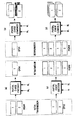
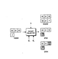
図8Aは前記1/2の符号率が適用された送信器のパケット選択部620で再伝送時に遂行される伝送パケットの決定方法を示した図である。
前記図8AでSはシステマテックビットのみに構成されたデータパケット(Sパケット)を意味し、Pはパリティビットのみに構成されたデータパケット(Pパケット)を意味する。前記図8Aのように、1/2の符号率の場合、前記Sパケットと前記Pパケットの大きさは同一である。前記図8Aでは説明の便宜のため、Sパケットは同一の大きさの二つのサブパケット(S0、S1)に区分し、Pパケットも同一の大きさの二つのサブパケット(P0、P1)に区分して示した。
【0059】
先ず、変調方式が変更される場合、実際伝送されるべきであるデータ量は下記<式1>と<式2>により決定することができる。
【0060】
【数1】
前記<式1>で、Miは初期伝送時の変調方式を示し、Mrは再伝送時の変調方式を示す。また、前記<式2>で、Diは初期伝送時に伝送した符号化ビットの数を示し、Drは再伝送時に伝送することができる符号化ビットの数を示す。
前記<式1>と前記<式2>で各変調方式に相応する値は、それぞれ64(64QAM)、16(16QAM)、8(8PSK)及び4(QPSK)である。
【0062】
前記図8Aは初期伝送の変調方式が16QAMであり、再伝送時の変調方式が64QAM、8PSK及びQPSKに変化される時の伝送されるデータパケットを選別する過程を示している図である。初期伝送時は全体データパケット、即ちS0、S1、P0及びP1が所定のシンボルマッピング方式に基づいて、4ビットに1シンボルにマッピングが遂行される。もし、再伝送時、変調方式が64QAMの高次変調方式に変化されると、前記<式1>と前記<式2>に基づいて1.5倍の符号化ビットが必要になる。これは現在符号化された全体符号化ビットだけではなく、その1/2の符号化ビットがもう必要になることを意味する。この場合、本発明では前記再伝送時に、初期伝送された全体符号化ビットを伝送し、さらにシステマテックビット全体、またはパリティビット全体をもう一度伝送するようになる。即ち、前記図8Aの場合、前記送信器は前記再伝送時、(S0、S1、P0、P1、S0、S1)、または(S0、S1、P0、P1、P0、P1)形態にデータパケットを伝送するようになる。この場合、受信器では同一サブパケット単位へのコンバインを遂行することができるとの利点がある。
【0063】
前記再伝送時、前記変調方式が前記64QAM方式に変化される時とは異なり、8PSK、またはQPSKの低次変調方式に変化される時には、前記<式1>及び前記<式2>により初期伝送時に伝送されたパケットの一部分、即ち全体パケットのそれぞれ3/4倍、1/2倍のデータビットが必要になる。前記変化可能な低次変調方式それぞれに対して、前記パケット選択部620は伝送のため、下記のようなサブパケットを選択することができる。
8PSK:(S0、S1、P0)、または(S0、S1、P1)、または(P0、P1、S0)、または(P0、P1、S1)
QPSK:(S0、S1)、または(P0、P1)
【0064】
前記のように多数の組み合わせが可能な理由は、ターボデコーダの性能を高めるためには、システマテックビット及びパリティビットの重要度が場合によって変わることができるからである。従って、再伝送回数、チャネル状態などによって、同一の組み合わせのサブパケット、または異なる組み合わせのサブパケットを伝送することにより、システムの性能向上を期待することができる。上述した既存の方式のように、システマテックビットとパリティビットが混じっているパケットを伝送する場合、チャネル符号化器612で符号化されたデータパケットの一部分のみが伝送されるべきであるので、結果的にランダムにコンバインされるしかない。このような方式はビット誤り率の低減には効果的であるが、フレームエラー率の低減には相対的に効果的ではない。これと異なり、本発明による送信器ではシステマテックビット、またはパリティビットのみに構成されたパケット全体をもう一度伝送する。これは、既に伝送された情報ビット全体に対するコンバイン効果を獲得し、ターボ復号器の入力端にコンバインされた符号化ビットを提供することにより、フレームエラーを低減できるからである。
【0065】
1.2 受信動作
次に、上述した送信器に対応して図7で示している受信器の構造を参照してデータを受信する動作を説明する。
1.2.1 受信データ復調(図11の1110段階)
前記送信器から受信されるデータは逆拡散部712により前記送信器で伝送時に使用された多重直交符号を利用して変調シンボルに逆拡散され、前記逆拡散されたシンボルはマルチプレクシングされ、一つのデータストリームの形態に直列出力される。復調部714は前記送信器の変調部622で使用された変調方式に対応する復調方式により、前記データストリームを復調させ、符号化ビットに対するLLR値を発生させ分配部716に出力させる。
【0066】
1.2.2 復調シンボル分配(図11の1112段階)
前記分配部716は前記復調された符号化ビットのLLR値を初期伝送、現在の変調方式、及び再伝送回数の情報に応じてコンバイナ718のシステマテックサブパケット、またはパリティサブパケットバッファに分配する。例えば、前記復調部714から復調された符号化ビットは、システマテックサブパケットとパリティサブパケットに構成される。従って、前記分配部716は前記復調部714からの符号化ビットをシステマテックサブパケットとパリティサブパケットに分離して出力することができる。
【0067】
1.2.3 コンバイン遂行(図11の1114段階)
前記分配部716からの出力はシステマテックサブパケットとパリティサブパケットに分離され出力されるので、コンバイナ718は前記システマテックサブパケットと前記パリティサブパケットを区分して貯蔵する二つのバッファを有する。従って、前記コンバイナ718は前記分配部716からのシステマテックサブパケットを第1バッファに貯蔵し、前記パリティサブパケットは第2バッファに貯蔵する。一方、前記分配部716からのシステマテックサブパケットとパリティサブパケットが再伝送されたサブパケットであれば、前記コンバイナ718は前記分配部716からのシステマテックサブパケットとパリティサブパケットを以前に貯蔵されたシステマテックサブパケット、またはパリティサブパケットとコンバインする。前記以前に貯蔵されたシステマテックサブパケットと前記パリティサブパケットは、初期伝送時に貯蔵されるか、以前再伝送により貯蔵された符号化ビットである。一方、再伝送時には変調方式が変化できることによって、前記再伝送時に前記分配部716から提供されるシステマテックサブパケットは、初期伝送時、または以前再伝送時に提供されたシステマテックサブパケットと相異なることができ、前記再伝送時に前記分配部716から出力されるパリティサブパケットも初期伝送時、または以前再伝送時に提供されたパリティサブパケットと相異なることができる。従って、前記コンバイナ718は前記分配部716から提供されるシステマテックサブパケット、またはパリティサブパケットに対する部分的なコンバインを遂行することができる。即ち、前記再伝送時に使用された変調方式による伝送データ量が初期伝送、または以前再伝送時に使用された変調方式による伝送データ量より少ない場合には、部分的なコンバインを遂行する。しかし、前記再伝送時に使用された変調方式による伝送データ量が初期伝送、または以前再伝送時に使用された変調方式による伝送データ量と同一の場合には、伝送されたすべての符号化ビットに対してコンバインを遂行する。一方、前記再伝送時に使用された変調方式による伝送データ量が初期伝送、または以前再伝送時に使用された変調方式による伝送データ量より多い場合には、伝送されたすべての符号化ビットに対してコンバインを遂行した後、反復伝送された符号化ビットに対する部分的なコンバインを追加に遂行する。
【0068】
上述したように前記コンバイナ718はシステマテックサブパケットを貯蔵するための第1バッファとパリティサブパケットを貯蔵するための第2バッファに構成されるが、前記第1バッファと前記第2バッファは前記送信器からのデータが正常的に処理される場合、次に伝送されるデータを貯蔵するため、初期化される。しかし、前記送信器からのデータが正常的に処理されなく、前記送信器への再伝送要請が遂行される場合には、前記第1バッファ及び第2バッファに貯蔵されたシステマテックサブパケットとパリティサブパケットは、コンバインのためそのまま維持される。前記コンバイナ718は再伝送時に変化される変調方式によりコンバインを遂行するために、変化された変調方式を予め知っているべきである。前記変化された変調方式は下向専用物理制御チャネル(DPCCH)のような下向制御チャネルを通じて前記送信器から提供されることができる。前記送信器から提供された前記変調方式は、前記送信器の上位階層(図示せず)から前記コンバイナ718に提供される。
【0069】
1.2.4 デインタリービング(図11の1116段階)
前記コンバイナ718によりコンバインされた符号化ビットはデインタリーバ710に出力される。前記デインタリーバ710も前記コンバイナ718に対応して二つのデインタリーバ720、722に構成されることができる。前記二つのデインタリーバ中、第1デインタリーバ720は前記コンバイナ718から提供されるシステマテックビットを受信し、所定パターンにより前記システマテックビットに対するデインタリービング動作を遂行する。また、前記二つのデインタリーバ中、第2デインタリーバ722は前記コンバイナ718から提供されるパリティビットを受信し、所定パターンにより前記パリティビットに対するデインタリービング動作を遂行する。前記第1デインタリーバ720と前記第2デインタリーバ722は前記送信器を構成するインタリーバ610でインタリービングのため使用したパターンに対応するパターンによりデインタリービング動作を遂行する。このためには前記送信器のインタリーバ610で使用したインタリービングパターンが前記第1デインタリーバ720と前記第2デインタリーバ722にそれぞれ提供されるべきである。前記送信器のインタリーバ610で使用したインタリービングパターンは、下向専用物理制御チャネル(DPCCH)のような下向制御チャネルを通じて前記送信器から提供されることができる。前記送信器から提供された前記インタリービングパターンは、前記送信器の上位階層(図示せず)から前記第1デインタリーバ720と前記第2デインタリーバ722にそれぞれ提供される。
【0070】
1.2.5 チャネル復号化遂行(図11の1118段階)
前記送信器で使用された所定の方式にそれぞれデインタリービングされた前記符号化ビットは、チャネル復号部724に提供され、所定の復号方式により復号化過程を遂行するようになる。この時、初期伝送時に伝送された全体符号化ビットに対して、システマテックビット、またはパリティビット全体がコンバインされることにより、前記復号部724に入力されるデータの信頼度が向上され、結果的に全体システムの性能が向上される。上述したように、前記チャネル復号部724は符号化ビットに対する復号を遂行するためには前記送信器で使用された変調方式を予め知っているべきである。上述したように前記送信器から下向専用物理制御チャネル(DPCCH)のような下向制御チャネルを通じて変調方式情報が提供されることができる。前記送信器から提供された前記変調方式は前記送信器の上位階層(図示せず)に提供され、前記上位階層により前記チャネル復号部724に提供される。前記変調方式は再伝送ごとに変更できるので、前記変調方式情報は再伝送時、または変調方式が変更されるごとに前記送信器から前記受信器に提供されるべきである。
【0071】
一方、前記チャネル復号部724により復号された前記情報ビットは、内部に含まれているCRCビットを利用してエラー検査を遂行することにより、前記情報ビットにエラーが発生したかを判断する。前記CRC検査部によりエラー発生が検査されると、前記上位階層は前記送信器に再伝送を要求するNACKを伝送し、エラー発生が検査されないと、受信を確認するACKを伝送する。前記NACKが伝送される場合、エラーが発生した符号化ビットは、前記コンバイナ718のパケットバッファにそのまま貯蔵され、前記ACKが伝送される場合、前記パケットバッファは次に伝送される新しいパケットを貯蔵するため初期化される。
【0072】
前記図8Aに例示された変調方式に従って再伝送されたパケットが前記図7の分配器716及びコンバイナ718で初期伝送されたパケットとコンバインされる過程を図9Aに示した。前記図9Aを参照してコンバイン過程を説明すると、先ず初期伝送時の変調方式より再伝送時の変調方式が高次である場合、前記<式1>及び前記<式2>により初期伝送パケットより大きなパケットが伝送されるので、全体パケットに対して十分なコンバイン効果を得ることができる。前記図8Aから分かるように、再伝送時の変調方式が64QAMの場合、一度の再伝送を通じて二つのシステマテックパケットと一つのパリティパケットが伝送されるので、コンバイン利得はより大きくなる。参考に、前記図8Aと前記図9Aで網かけ処理されたブロックは伝送されないパケットを意味する。
【0073】
これとは反対に、再伝送時の変調方式が初期伝送時の変調方式に比べて低次である場合、前記<式1>及び前記<式2>により初期伝送パケットの一部分が再伝送される。この時、再伝送されたシステマテックパケット、またはパリティパケットが選別的に初期伝送パケットとコンバインされる。一例に前記図8Aで再伝送時の変調方式が8PSKの場合、一度の再伝送を通じて1個のシステマテックパケットと1/2のパリティパケット(一つのサブパケット)のみが伝送される。前記再伝送時の変調方式がQPSKである場合、一度の再伝送を通じて1個のシステマテックパケットのみが伝送されるので、コンバインは初期伝送されたパケット全体に対して部分的に遂行される。しかし、システマテックパケット全体に対してコンバインを遂行できるので、前記ターボコードの特性上、情報ビット全体に対してコンバインされた効果を得ることができる。その結果、全般的に前記チャネル復号器の性能が向上され、フレームエラー率を低減できるようになる。
【0074】
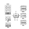
2.第2実施形態(符号率が3/4である場合)
符号率が1/2の場合とは異なり、符号率が3/4の場合には、チャネル符号化器612からの符号化ビット中、システマテックビットはパリティビットの3倍になる。これは第1インタリーバ616に提供される符号化ビットの数が第2インタリーバ618に提供される符号化ビット数の3倍になることを意味する。理解を助けるため、図8Bにその概念を示した。前記符号率が1/2の場合のように、初期伝送時の変調方式に16QAMを使用し、再伝送時に64QAM、8PSK及びQPSKに変調方式が変化される時、伝送されるパケットの単位を示すために、便宜上、システマテックパケットを同一の大きさを有するサブパケットS0、S1、S2に区分した。
【0075】
本発明の第2実施形態に従う送信器及び受信器の機能は、前記1/2の符号率である場合の第1実施形態で提示したことと同一であるので、これに対する詳細な説明は省略する。ここでは前記図6のパケット選択部620と前記図7の分配部716及びコンバイナ718の機能を重点的に説明する。
【0076】
前記パケット選択部620は初期伝送、現在の変調方式及び再伝送回数に対する変調方式に対する制御情報に応じて再伝送時に伝送するデータパケットを選択する。この時、再伝送時に伝送される符号化ビットの数は、前記<式1>と前記<式2>を通じて同一に決定される。即ち、64QAM、8PSK及びQPSKに対する再伝送パケットの大きさは、初期伝送時に伝送されたパケット大きさに比べてそれぞれ3/2、3/4及び1/2倍になる。これに対する一例に図8Bで前記パケット選択部620により決定された再伝送パケットの組み合わせ例を示しており、以外にも次のような組み合わせを予想することができる。
64QAM:(S0、S1、S2、S0、S1、P)、または(S0、S1、S2、S1、S2、P)、または(S0、S1、S2、S0、P、P)
8PSK:(S0、S1、S2)、または(P、P、P)
QPSK:(S0、S1)、または(S1、S2)、または(P、P)
【0077】
前記例以外にも前記パケット選択部620は各種組み合わせ形態にシステマテックビット、またはパリティビットのみに構成されたパケットを選択することができる。前記符号率が1/2の場合と同一に、パケット選択のパターンは各変調方式及び再伝送回数に応じて順次的に予め決定することもでき、またはいずれか一つの組み合わせに一貫的に伝送することもできる。前記のように予め指定されたパケット選択方式は受信器でも知っているべきであり、これを通じて前記分配部716及びコンバイナ718で適切に機能することができる。
【0078】
しかし前記図8Bから分かるように、符号率が非対称である場合、一例に3/4の場合には、前記1/2の符号率の場合とは異なり、変調方式の変化に応じてシステマテックパケットを全体的に選択して再伝送することができないので、前記1/2の符号率の場合に比べてフレームエラーに対する性能が少し低下される問題点がある。この場合、受信端ではさらに再伝送を要求する可能性が高く、再伝送時に前記例で示した再伝送パケット組み合わせを変更することにより、前記初期伝送された全体パケットに対するコンバイン効果を得ることができる。即ち、2回の再伝送を通じて初期伝送されたパケット全体に対して少なくとも一度のコンバインを遂行できるようになる。
【0079】
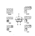
図9Bは前記符号率が3/4の場合、前記図8Bの各変調方式に応じて選択再伝送されたパケットを前記分配部716で該当コンバイナ718のバッファに分離し、前記コンバイナ718のバッファに貯蔵された初期伝送パケット及び以前に再伝送されたパケットとコンバインする過程の例を示したものである。一例に、前記再伝送時に変調方式に64QAMを使用する場合、一度の再伝送に前記初期伝送パケットと十分なコンバイン効果を得ることができる。前記再伝送時に変調方式に8PSKを使用する場合、一度の再伝送にシステマテックパケットに対するコンバイン効果を得ることができる。一方、前記再伝送時に変調方式にQPSKを使用する場合には、システマテックパケット全体の2/3に対する部分的なコンバイン効果のみを得ることができる。従って、この場合、もう一度の再伝送を通じてシステマテックパケットとパリティパケット全体に対するコンバイン効果を得ることができる。前記図9Bではシステマテックパケットを優先的に考慮した組み合わせの場合の例を示したものであり、これはシステマテックビットを優先的に補償する時、チャネル復号器に入力される符号化ビットの信頼度が向上されるからである。
【0080】
上述した本発明の実施形態において、パケット選択部はシステマテックパケット、またはパリティパケットを選択出力する時、その単位をサブパケット単位、またはパケット単位に選択することができる。また、コンバイナは受信されるシステマテックパケット、またはパリティパケットをサブパケット、またはパケット単位にコンバインを遂行することができる。
【0081】
【発明の効果】
上述したように本発明は再伝送時にチャネル状況に応じて変調方式が変化され、初期伝送パケットの部分のみを再伝送すべきである高速無線パケットデータ通信で、重要度が高いパケットを選別的に伝送することにより、ターボ復号器入力ビットLLR値に対する信頼度を増大させる。従って、既存のシステムに比べて、フレームエラー率を低くして、優秀な伝送効率を得ることができる。また本発明は有/無線通信などすべての送/受信装置に応用できるだけではなく、現在3GPPと3GPP2標準化会議で論議中であるHSDPA及び1xEV−DVに活用されると、システム全般の性能を向上させることができる。
【図面の簡単な説明】
【図1】 通常的な高速データ伝送のための符号分割多重接続移動通信システムで送信器構造の一例を示している図である。
【図2】 図1でのチャネル符号化部の詳細構成を示している図である。
【図3】 従来の高速データ伝送のための符号分割多重接続移動通信システムで再伝送時に変調方式が変化する送信器構造を示している図である。
【図4】 図3での送信器に対応した受信器構造を示している図である。
【図5】 従来の変調方式の変化に対応した符号化とコンバイン例を示している図である。
【図6】 本発明の実施形態に従う符号分割多重接続移動通信システムでの送信器構造を示している図である。
【図7】 本発明の実施形態に従う符号分割多重接続移動通信システムでの受信器構造を示している図である。
【図8A】 本発明の実施形態に従って再伝送時に変調方式が変更される場合、送信器で伝送するパケットを選択する例を示している図である。
【図8B】 本発明の実施形態に従って再伝送時に変調方式が変更される場合、送信器で伝送するパケットを選択する例を示している図である。
【図9A】 本発明の実施形態に従って再伝送時に変調方式が変更される場合、受信器で受信したパケットを分配する例を示している図である。
【図9B】 本発明の実施形態に従って再伝送時に変調方式が変更される場合、受信器で受信したパケットを分配する例を示している図である。
【図10】 本発明の実施形態に従う符号分割多重接続移動通信システムの送信器で遂行する動作を示している処理流れ図である。
【図11】 本発明の実施形態に従う符号分割多重接続移動通信システムの受信器で遂行する動作を示している処理流れ図である。
【符号の説明】
612 チャンネル符号化部
614 分配部
616・618 インターリーバ
620 パケット選択部
622 変調部
624 周波数拡散部
626 制御部
712 逆拡散部
714 復調部
716 パケット分配部
718 コンバイナ[0001]
BACKGROUND OF THE INVENTION
The present invention relates to a data transmission / reception apparatus and method in a code division multiple access mobile communication system, and more particularly, to an apparatus and method for transmitting / receiving data by applying a modulation scheme changed at the time of retransmission.
[0002]
[Prior art]
Currently, mobile communication systems have evolved from the provision of initial voice-centric services to high-speed, high-quality wireless data packet communication systems for providing data services and multimedia services. In addition, at present, standardization work for high-speed, high-quality wireless data packet services is being performed in the third generation mobile communication system that is divided into the asynchronous method (3GPP) and the synchronous method (3GPP2). As an example, standardization work for High Speed Downlink Packet Access (hereinafter referred to as HSDPA) system is in progress in 3GPP, and standardization work for 1xEV-DV is in progress in 3GPP2. Such standardization work can be regarded as a typical disproval of an effort to find a solution for a high-speed, high-quality wireless data packet transmission service of 2 Mbps or higher in a third generation mobile communication system. Based on the above provision of high-speed, high-quality multimedia services.
[0003]
Most of the factors that interfere with high-speed, high-quality data services in wireless communications result from the wireless channel environment. The radio channel has a frequent channel environment due to changes in signal power due to white noise and fading, shadowing, Doppler effect due to terminal movement and frequent speed changes, interference due to other users and multipath signals, etc. To change. Therefore, in order to provide the high-speed wireless data packet service, in addition to the general technology provided in the existing two-generation or three-generation mobile communication systems, other advances that can increase the adaptability to channel changes. Technology is needed. The high-speed power control method adopted in the existing system also increases the adaptability to channel changes. However, 3GPP and 3GPP2, which are proceeding with the high-speed data packet transmission system standard, commonly refer to Adaptive Modulation / Coding Scheme (AMCS) and Hybrid Automatic Repeat Request (HARQ). Has been.
[0004]
The adaptive modulation / coding scheme is a method of changing the modulation scheme and the code rate of the channel encoder in accordance with a change in the channel environment of the downlink. In general, the channel environment of the downlink is mainly that a terminal measures a signal-to-noise ratio (SNR) and transmits information on the signal-to-noise ratio to the base station through the uplink. Meanwhile, the base station predicts the environment of the downward channel based on the information, and specifies an appropriate modulation scheme and code rate according to the predicted value. 8PSK, 16QAM, 64QAM, etc. are considered, and 1/2 and 3/4 are considered for the coding rate of the channel encoder, so that a base station is used in a system using an adaptive modulation / coding scheme. For a terminal having a good channel environment such as a nearby terminal, a high-order modulation method (16QAM, 64QAM) and a
[0005]
In the complex retransmission scheme, when an error occurs in an initially transmitted data packet, a retransmission of the packet is required to compensate for the erroneous packet. At this time, a predetermined link control technique used is determined. means. In general, the above-mentioned complex retransmission scheme includes a chase combining scheme (hereinafter referred to as CC), an overall redundancy increment scheme (Full Incremental Redundancy, hereinafter referred to as FIR) and a partial redundancy increment scheme (hereinafter referred to as PIR). Can be divided into
[0006]
The CC is a method for transmitting the same whole packet as that for initial transmission at the time of retransmission, and the receiving end combines the retransmitted packet and the initial transmission packet stored in the reception buffer by a predetermined method. In this way, the reliability of the coded bits input to the decoder can be improved and an overall system performance gain can be obtained. At this time, combining the same two packets has an effect similar to that of iterative coding, and thus an average performance gain of about 3 dB can be obtained.
[0007]
The FIR is a method for improving the performance of a decoder at the receiving end by transmitting a packet composed only of surplus bits generated by a channel encoder instead of the same packet. That is, at the time of decoding, not only the initially transmitted information but also new surplus bits are used, thereby reducing the coding rate and increasing the performance of the decoder. In general, it is a well-known matter in coding theory that the performance gain due to a low code rate is higher than the performance gain due to repetitive coding. Therefore, when only the performance gain is considered, the FIR exhibits better performance than the CC.
[0008]
Unlike the FIR, the PIR is a method of transmitting a data packet in which information bits and new surplus bits are combined during retransmission. Accordingly, by combining the information bits with the initially transmitted information bits at the time of decoding, an effect similar to CC can be obtained. By decoding using the remainder bits, an effect similar to FIR can be obtained. Can be obtained. At this time, the PIR has a slightly higher coding rate than the FIR, and exhibits an intermediate performance between the FIR and the CC. However, since the complex retransmission technique should consider not only the performance but also the complexity of the system such as the buffer size and signaling of the receiver, it is not easy to determine any one of them.
[0009]
The adaptive modulation / coding scheme and the complex retransmission scheme are independent techniques for increasing the adaptability to link changes, but the combined use of the two schemes greatly improves system performance. be able to. That is, when a modulation scheme and a code rate of the channel encoder suitable for the downward channel condition are determined by the adaptive modulation / coding scheme, a data packet corresponding to the modulation scheme is transmitted, and the received data is transmitted at the receiving end. If the decoding of the packet fails, request retransmission. The base station receives a retransmission request from the receiving end and retransmits a predetermined data packet by the composite retransmission method.
[0010]
FIG. 1 shows an example of an existing transmitter for high-speed packet data transmission. By controlling the
Referring to FIG. 1, the
[0011]
Referring to FIG. 2, an input transmission frame is output to a systematic bit frame (X) as it is, and at the same time, input to the
[0012]
On the other hand, as described above, the form in which encoded bits are punctured by the
[0013]
Referring to FIG. 1, the packet data transmission process of the system embodying the adaptive modulation / coding scheme and the composite retransmission scheme will be described. Before transmitting a new packet, the
[0014]
The interleaving technique makes the order of the input bits different so that the damage of data symbols is not concentrated in one place in the fading environment, but distributed in many places, so that a burst error is generated. This is a technology to prevent the occurrence of For convenience of explanation, it is assumed that the size of the
[0015]
In the transmitter structure of the high-speed packet transmission system of FIG. 1, it is assumed that the modulation scheme and code rate determined by the adaptive modulation / coding scheme at the time of initial transmission are applied without change at the time of retransmission. However, as described above, the situation of the high-speed data transmission channel can be sufficiently changed during the complex retransmission period due to a change in the number of call terminals in the cell and a change in Doppler. Therefore, maintaining the modulation / coding scheme used at the time of initial transmission can result in a reduction in system performance.
[0016]
For this reason, the ongoing standardization of HSDPA and 1xEV-DV considers a method that can change the modulation / coding scheme even during the retransmission period. For example, when the retransmission modulation system changes in a system that uses CC for the complex retransmission system, a part or the whole of the initially transmitted data packet is retransmitted at the transmitting end, and the partially retransmitted data is transmitted at the receiving end. The packet is partially combined with the initial packet that was initially transmitted. This results in a lower overall bit error rate of the decoder. The structure of the transmitter is shown in FIG. 3, and the structure of the receiver is shown in FIG.
[0017]
As can be seen from the transmitter structure of FIG. 3, the above-described scheme is the addition of a
[0018]
FIG. 4 shows a receiver structure corresponding to the transmitter structure of FIG. A
[0019]
FIGS. 5A and 5C show an example of a change in the size of a packet transmitted through the
First, it can be seen from FIG. 5A that when the modulation rate is lower than the initial transmission during the retransmission, the coded bits output from the
[0020]
Next, it can be seen from FIG. 5C that when the modulation rate is higher at the time of retransmission than at the initial transmission, the coded bits output from the
[0021]
FIGS. 5B and 5D show an example in which received packets due to a change in modulation scheme at the time of initial transmission and retransmission are combined through a
First, when the modulation rate is lower than the initial transmission at the time of retransmission, that is, when 16QAM is used at the time of initial transmission and QPSK is used at the time of retransmission, only 1/2 of the packet initially transmitted through the retransmission is additionally received. The This is shown in detail in FIG. 5B. Accordingly, the
[0022]
Next, when the modulation rate is higher at the time of retransmission than at the initial transmission, that is, when QPSK is used at the time of initial transmission and 16 QAM is used at the time of retransmission, the packet initially transmitted through retransmission is received twice more. Therefore, the
[0023]
In the high-speed packet transmission system using CC for the complex retransmission scheme, the modulation scheme can be changed even during retransmission by using the
[0024]
[Problems to be solved by the invention]
An object of the present invention to solve the above-described problems is to provide a data transmission / reception apparatus and method for improving the performance of a wireless communication system.
It is another object of the present invention to provide a data transmission / reception apparatus and method capable of receiving data bits with a higher reception probability in a wireless communication system.
Yet another object of the present invention is to use a channel interleaver independently applied to the systematic bits and parity bits at the output of the turbo code and a corresponding de-interleaver at the receiving end to achieve more efficient high-speed data. It is to provide a transmission / reception apparatus and method.
Still another object of the present invention is to improve efficiency by coordinating CC (Chase Combining) in a channel interleaver and composite retransmission technique (HARQ) applied independently to systematic bits and parity bits at turbo code output. It is an object to provide a high-speed data transmission / reception apparatus and method.
Still another object of the present invention is a transmission end of a high-speed wireless communication system in which adaptive modulation and coding techniques are required. Only the modulation scheme is adaptive while maintaining the same channel coding rate as the initial transmission at the time of retransmission. It is an object of the present invention to provide an apparatus and a method capable of obtaining a performance gain of a system by changing to the above.
Still another object of the present invention is to transmit one of data packets divided into systematic bits and parity bits according to a required modulation method at a transmitting end of a high-speed wireless communication system to which an adaptive modulation method is applied. It is an object of the present invention to provide a control apparatus and method capable of obtaining a performance gain of a system by selectively retransmitting.
Still another object of the present invention is to selectively soft combine a data packet selectively retransmitted by a modulation scheme required at a transmitting end of a high-speed wireless communication system with a data packet initially transmitted at a receiving end. Thus, it is an object of the present invention to provide a control apparatus and method that can obtain a performance gain.
[0025]
[Means for Solving the Problems]
In a first aspect for achieving the above object, the present invention includes a turbo encoder having a given code rate, and uses any one of a plurality of modulation schemes to transmit data to the turbo code. A transmitter of a code division multiple access mobile communication system that initially transmits systematic bits and parity bits encoded by a receiver, and performs retransmission of the data according to a retransmission request from a receiver. A process of determining a modulation scheme to be used between a transmitter and the receiver; a process of distributing coded bits encoded at the predetermined code rate into systematic bits and parity bits; and the determined modulation scheme If the modulation scheme is different from the modulation method used during the initial transmission, the determination is made in the systematic bits and the parity bits during the initial transmission. Comprising the steps of a possible coded bits transmitted by the modulation method and transmits the converted to modulation symbols based on the determined modulation scheme, characterized in that it comprises a.
[0026]
In a second aspect for achieving the above object, the present invention includes a turbo encoder having a given code rate, and uses any one of a plurality of modulation schemes to transmit data to the turbo code. An apparatus for performing retransmission of data according to a retransmission request from a receiver in a transmitter of a code division multiple access mobile communication system that initially transmits systematic bits and parity bits encoded by a receiver, and at the time of the retransmission request, A control unit that determines a modulation scheme to be used between the transmitter and the receiver; a distribution unit that distributes encoded bits encoded at the predetermined code rate into systematic bits and parity bits; and the determined modulation If the scheme is different from the modulation scheme used during the initial transmission, the systematic bit and the parity bit during the initial transmission, A selection unit that outputs encoded bits that can be transmitted by a predetermined modulation method, and a modulation unit that converts the transmitted encoded bits into modulation symbols based on the determined modulation method and transmits the encoded bits. It is characterized by.
[0027]
In a third aspect for achieving the above object, the present invention includes a turbo encoder having a given code rate, and uses any one of a plurality of modulation schemes to transmit data to the turbo code. Modulation retransmitted from a transmitter of a code division multiple access mobile communication system that initially transmits systematic bits and parity bits encoded by a transmitter as modulation symbols according to a predetermined modulation scheme, using a modulation scheme different from the modulation scheme at the time of initial transmission In the method of receiving a symbol, the process of outputting the modulation symbol to a coded bit based on a demodulation method corresponding to the modulation method used at the time of retransmission, and the coded bit is configured to the systematic bit Separating the systematic packet into a parity packet composed of the parity bits; The process of combining a matech packet with a previously received systematic packet, combining the parity packet with a previously received parity packet, and decoding information bits from the combined systematic packet and the combined parity packet. And a process.
[0028]
In a fourth aspect for achieving the above object, the present invention includes a turbo encoder having a given code rate, and uses any one of a plurality of modulation schemes to transmit data to the turbo code. Modulation retransmitted from a transmitter of a code division multiple access mobile communication system that initially transmits systematic bits and parity bits encoded by a transmitter as modulation symbols according to a predetermined modulation scheme, using a modulation scheme different from the modulation scheme at the time of initial transmission In a symbol receiving apparatus, a demodulator that outputs the modulation symbols to encoded bits based on a demodulation scheme corresponding to the modulation scheme used at the time of retransmission, and the encoded bits are configured as the systematic bits. Packet distributor for separating the systematic packet and the parity packet composed of the parity bits A combiner that combines the systematic packet with a previously received systematic packet and combines the parity packet with a previously received parity packet; and the combined systematic packet and the information bit from the combined parity packet. And a decoding unit for decoding.
[0029]
DETAILED DESCRIPTION OF THE INVENTION
Hereinafter, preferred embodiments of the present invention will be described in detail with reference to the accompanying drawings. In the following invention, for the purpose of clarifying only the gist of the present invention, a detailed description of related known functions or configurations will be omitted. First, in the detailed description according to the embodiment of the present invention, which will be described later, the code rate of the channel encoder supports 1/2 and 3/4, and initial transmission is performed during the modulation schemes of QPSK, 8PSK, 16QAM, and 64QAM. An embodiment is proposed for the case where the 16QAM system is changed to another modulation system at the time of retransmission. Further, in the detailed description to be described later, only the case of using the chase combine in the complex retransmission format will be described.
[0030]
Hereinafter, embodiments of the present invention will be described with reference to the accompanying drawings.
FIG. 6 is a diagram illustrating a transmitter configuration of the code division multiple access mobile communication system according to the embodiment of the present invention.
Referring to FIG. 6, the controller (AMCS) 626 controls the overall operation of the transmitter according to the embodiment of the present invention. In particular, the
[0031]
The
[0032]
A distribution unit (Distributor) 614 distributes the systematic bits and the parity bits input from the
[0033]
The
[0034]
The
[0035]
Meanwhile, as described above, the
[0036]
The
[0037]
A
[0038]
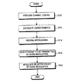
FIG. 10 is a process flow diagram showing the operation sequence of the transmitter according to the above-described embodiment of the present invention. As shown in FIG. 10, the operation of the transmitter according to the embodiment of the present invention includes encoding the data to be transmitted and distributing the encoded bits by the encoding, After performing interleaving on each of the distributed coded bits, select a coded bit to be transmitted among the interleaved coded bits according to a modulation scheme that can be changed for each initial transmission and retransmission, and And a process of modulating according to a modulation method.
[0039]
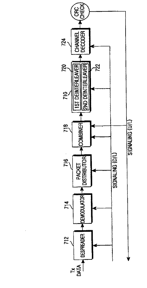
FIG. 7 shows a receiver structure according to an embodiment of the present invention corresponding to the transmitter shown in FIG.
Referring to FIG. 7, a data symbol (Tx Data) that is frequency-spread and transmitted from a transmitter using multiple orthogonal codes is received through a downward traffic channel. The
[0040]
The
[0041]
The
[0042]
The
[0043]
For example, if only a systematic packet is transmitted from the transmitter during retransmission, the
[0044]
The
[0045]
The
[0046]
At this time, depending on whether ACK or NACK is transmitted as a confirmation signal, the first buffer and the second buffer of the
[0047]
On the other hand, as can be seen from the above configuration, the receiver knows in advance information on the code rate, modulation scheme, orthogonal code, and number of retransmissions used in the transmitter of FIG. 6 for operations such as demodulation and decoding. Should be. That is, the information described above is preliminarily stored in the
[0048]
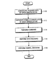
FIG. 11 is a process flow diagram showing an operation sequence of the receiver according to the above-described embodiment of the present invention. As shown in FIG. 11, the operation of the receiver according to the embodiment of the present invention includes a process of demodulating received data and distributing demodulated symbols according to a modulation scheme used in the transmitter. And combining each demodulated symbol with a previously received demodulated symbol and then channel decoding the encoded bits output through deinterleaving.
[0049]
First, before describing the operation according to the embodiment of the present invention in detail, the embodiment to be proposed in the present invention will be briefly described as follows.
The first embodiment proposed in the present invention is a code division multiple access mobile communication system that supports CC in a ½ code rate and composite retransmission scheme, and uses different modulation schemes for initial transmission and retransmission. Proposed transmitters and receivers to support. At this time, 16QAM is used as a modulation method during initial transmission, and 64QAM, 8PSK, and QPSK are used as modulation methods during retransmission. In detail, a method is proposed in which a coded bit to be transmitted is selected according to a modulation scheme changed at the time of retransmission by a transmitter, and this is effectively combined by a receiver.
[0050]
The second embodiment proposed in the present invention is a code division multiple access mobile communication system that supports 3/4 code rate and CC in a complex retransmission scheme, and uses different modulation schemes for initial transmission and retransmission. Proposed transmitters and receivers to support. Also at this time, 16QAM is used as the modulation method during initial transmission, and 64QAM, 8PSK, and QPSK are used as modulation methods during retransmission. In detail, a method is proposed in which a coded bit to be transmitted is selected according to a modulation scheme changed at the time of retransmission by a transmitter, and this is effectively combined by a receiver.
[0051]
1. First embodiment (when the code rate is 1/2)
Hereinafter, the operation according to the first embodiment of the present invention will be described in detail with reference to the above-described drawings. First, the first embodiment of the present invention described later uses a code rate of 1/2 and uses CC for the composite retransmission scheme. Further, it is assumed that the modulation scheme at the time of initial transmission is 16QAM, and that the same number of orthogonal codes as at the time of initial transmission are used at the time of retransmission.
[0052]
1.1 Transmission operation
1.1.1 Channel coding (
The transmission data to which the CRC is added is input to the
[0053]
1.1.2 Coded bit distribution (
The encoded bits serially output from the
[0054]
1.1.3 Interleaving (
The systematic bits distributed from the
[0055]
1.1.4 Packet selection (
The interleaved systematic bits and the interleaved parity bits provided from the
[0056]
1.1.5 Modulation by current modulation method (
The selected subpacket from the
[0057]
As described with reference to
[0058]
Next, an example in which the
FIG. 8A is a diagram illustrating a transmission packet determination method performed at the time of retransmission by the
In FIG. 8A, S means a data packet (S packet) composed only of systematic bits, and P means a data packet (P packet) composed only of parity bits. As shown in FIG. 8A, when the code rate is 1/2, the size of the S packet and the P packet are the same. In FIG. 8A, for convenience of explanation, the S packet is divided into two subpackets (S0, S1) having the same size, and the P packet is also divided into two subpackets (P0, P1) having the same size. Showed.
[0059]
First, when the modulation scheme is changed, the amount of data to be actually transmitted can be determined by the following <
[0060]
[Expression 1]
In the above <
The values corresponding to the respective modulation schemes in <
[0062]
FIG. 8A illustrates a process of selecting data packets to be transmitted when the modulation scheme for initial transmission is 16QAM and the modulation scheme for retransmission is changed to 64QAM, 8PSK, and QPSK. During initial transmission, the entire data packet, that is, S0, S1, P0, and P1 are mapped to one symbol per 4 bits based on a predetermined symbol mapping scheme. If the modulation method is changed to a high-order modulation method of 64QAM at the time of retransmission, 1.5 times as many encoded bits are required based on <
[0063]
Unlike the time when the modulation method is changed to the 64QAM method at the time of the retransmission, the initial transmission is performed according to the <
8PSK: (S0, S1, P0), or (S0, S1, P1), or (P0, P1, S0), or (P0, P1, S1)
QPSK: (S0, S1) or (P0, P1)
[0064]
The reason why a large number of combinations are possible as described above is that the importance of systematic bits and parity bits can be changed depending on the case in order to improve the performance of the turbo decoder. Therefore, it is possible to expect an improvement in system performance by transmitting the same combination of subpackets or different combinations of subpackets depending on the number of retransmissions, channel conditions, and the like. When transmitting a packet in which systematic bits and parity bits are mixed as in the existing method described above, only a part of the data packet encoded by the
[0065]
1.2 Reception operation
Next, the operation of receiving data will be described with reference to the structure of the receiver shown in FIG. 7 corresponding to the transmitter described above.
1.2.1 Received data demodulation (
Data received from the transmitter is despread by the
[0066]
1.2.2 Demodulated symbol distribution (
The
[0067]
1.2.3 Combining (
Since the output from the
[0068]
As described above, the
[0069]
1.2.4 Deinterleaving (
The encoded bits combined by the
[0070]
1.2.5 Perform channel decoding (
The coded bits deinterleaved according to a predetermined scheme used in the transmitter are provided to a
[0071]
Meanwhile, the information bit decoded by the
[0072]
FIG. 9A illustrates a process in which a packet retransmitted according to the modulation method illustrated in FIG. 8A is combined with a packet initially transmitted by the
[0073]
On the other hand, when the modulation scheme at the time of retransmission is lower than the modulation scheme at the time of initial transmission, a part of the initial transmission packet is retransmitted by the above-mentioned <
[0074]
2. Second embodiment (when the code rate is 3/4)
Unlike the case where the code rate is 1/2, when the code rate is 3/4, the systematic bits in the encoded bits from the
[0075]
Since the functions of the transmitter and the receiver according to the second embodiment of the present invention are the same as those presented in the first embodiment when the code rate is ½, detailed description thereof will be omitted. . Here, the functions of the
[0076]
The
64QAM: (S0, S1, S2, S0, S1, P), or (S0, S1, S2, S1, S2, P), or (S0, S1, S2, S0, P, P)
8PSK: (S0, S1, S2) or (P, P, P)
QPSK: (S0, S1), or (S1, S2), or (P, P)
[0077]
In addition to the above example, the
[0078]
However, as can be seen from FIG. 8B, when the code rate is asymmetric, in the case of 3/4 as an example, unlike the case of the code rate of 1/2, the systematic packet is changed according to the change of the modulation method. Therefore, there is a problem that the performance with respect to frame errors is slightly deteriorated as compared with the case of the code rate of 1/2. In this case, there is a high possibility of requesting retransmission at the receiving end, and by combining the retransmission packet combination shown in the above example at the time of retransmission, it is possible to obtain a combine effect on the entire initially transmitted packet. . That is, it is possible to perform at least one combine on the entire initially transmitted packet through two retransmissions.
[0079]
In FIG. 9B, when the code rate is 3/4, the packet retransmitted selectively according to each modulation method of FIG. 8B is separated into the buffer of the
[0080]
In the above-described embodiment of the present invention, when the packet selector selects and outputs the systematic packet or the parity packet, the unit can select the unit as a sub-packet unit or a packet unit. Also, the combiner can combine the received systematic packet or parity packet into subpackets or packet units.
[0081]
【The invention's effect】
As described above, according to the present invention, the modulation scheme is changed according to the channel condition at the time of retransmission, and only the portion of the initial transmission packet should be retransmitted. By transmitting, the reliability for the turbo decoder input bit LLR value is increased. Therefore, the frame error rate can be lowered and excellent transmission efficiency can be obtained as compared with the existing system. In addition, the present invention can be applied not only to all transmission / reception devices such as wired / wireless communication, but also to improve the performance of the entire system when applied to HSDPA and 1xEV-DV currently under discussion at 3GPP and 3GPP2 standardization conferences. be able to.
[Brief description of the drawings]
FIG. 1 shows an example of a transmitter structure in a code division multiple access mobile communication system for normal high-speed data transmission.
FIG. 2 is a diagram illustrating a detailed configuration of a channel encoding unit in FIG. 1;
FIG. 3 is a diagram illustrating a transmitter structure in which a modulation scheme changes during retransmission in a conventional code division multiple access mobile communication system for high-speed data transmission.
4 is a diagram showing a receiver structure corresponding to the transmitter in FIG. 3;
FIG. 5 is a diagram illustrating coding and combining examples corresponding to changes in a conventional modulation scheme.
FIG. 6 is a diagram illustrating a transmitter structure in a code division multiple access mobile communication system according to an embodiment of the present invention.
FIG. 7 is a diagram illustrating a receiver structure in a code division multiple access mobile communication system according to an embodiment of the present invention;
FIG. 8A is a diagram illustrating an example of selecting a packet to be transmitted by a transmitter when a modulation scheme is changed during retransmission according to an embodiment of the present invention.
FIG. 8B is a diagram illustrating an example of selecting a packet to be transmitted by a transmitter when a modulation scheme is changed during retransmission according to an embodiment of the present invention.
FIG. 9A is a diagram illustrating an example of distributing a packet received by a receiver when a modulation scheme is changed during retransmission according to an embodiment of the present invention.
FIG. 9B is a diagram illustrating an example of distributing packets received by a receiver when a modulation scheme is changed during retransmission according to an embodiment of the present invention.
FIG. 10 is a process flow diagram illustrating operations performed by a transmitter of a code division multiple access mobile communication system according to an embodiment of the present invention.
FIG. 11 is a process flow diagram illustrating operations performed by a receiver of a code division multiple access mobile communication system according to an embodiment of the present invention.
[Explanation of symbols]
612 channel encoder
614 Distribution Department
616/618 Interleaver
620 packet selector
622 Modulator
624 Frequency spreader
626 control unit
712 Despreading part
714 Demodulator
716 Packet distribution unit
718 Combiner
Claims (16)
入力データをチャネル符号化して符号化ビットを出力する過程と、
前記符号化ビットからシステマテックビットとパリティビットを区分し、前記システマテックビットを優先的に選択してパケットを構成する過程と、
前記データパケットを第1の変調方式によってシンボルマッピングして伝送する過程と、
現在伝送時点で、前記システマテックビットと前記パリティビット中で、以前に伝送されないシステマテックビットと以前に伝送されないパリティビットを優先的に選択してパケットを構成する過程と、
前記データパケットをチャネル状況を考慮して決定された第2の変調方式によってシンボルマッピングして伝送する過程と、を含むことを特徴とする前記方法。In a method for retransmitting data packets in a mobile communication system ,
A process of channel-coding input data and outputting coded bits;
Separating systematic bits and parity bits from the encoded bits, and preferentially selecting the systematic bits to form a packet;
Transmitting the data packet by symbol mapping according to a first modulation scheme;
A process of preferentially selecting a systematic bit that has not been previously transmitted and a parity bit that has not been previously transmitted in the systematic bit and the parity bit at a current transmission time; and
And transmitting the data packet by symbol mapping according to a second modulation scheme determined in consideration of a channel condition .
ことを特徴とする請求項1に記載の方法。The method of claim 1, wherein the systematic bit is preferentially selected.
ことを特徴と請求項1に記載の方法。The method of claim 1, wherein if a systematic bit is preferentially selected during previous transmission, a parity bit is preferentially selected during retransmission .
ことを特徴とする請求項1に記載の方法。The method according to claim 1, wherein the systematic bits are preferentially selected for duplication together with the systematic bits and the parity bits.
ことを特徴とする請求項1に記載の方法。The method according to claim 1, wherein a systematic bit that has not been retransmitted before or a parity bit that has not been retransmitted is preferentially selected together with the systematic bit and the parity bit.
ことを特徴とする請求項1に記載の方法。The systematic bits are separated into a plurality of systematic subpackets, the parity bits are separated into a plurality of parity subpackets, and the coded bits are selected in units of the systematic subpackets or the parity subpackets. The method according to claim 1.
初期伝送のための第1の変調方式と再伝送のための第2の変調方式を決定する制御部と、
入力データをチャネル符号化して符号化ビットを出力するターボ符号化器と、
前記符号化ビットからシステマテックビットとパリティビットを区分し、初期伝送のときに、前記システマテックビットを優先的に選択してパケットを構成し、再伝送のときに、以前に伝送されないシステマテックビットと以前に伝送されないパリティビットを優先的に選択してデータパケットを構成するパケット選択部と、
前記データパケットを前記制御部により決定された第1の変調方式、または第2の変調方式によってシンボルマッピングして伝送する変調部と、を含むことを特徴とする前記装置。In an apparatus for retransmitting data packets in a mobile communication system ,
A controller that determines a first modulation scheme for initial transmission and a second modulation scheme for retransmission ;
A turbo encoder that channel-codes input data and outputs encoded bits;
Systematic bits and parity bits are distinguished from the coded bits, and at the initial transmission, the systematic bits are preferentially selected to form a packet, and at the time of retransmission, systematic bits that have not been transmitted before A packet selection unit that preferentially selects parity bits that have not been transmitted before and configures a data packet ;
A modulation unit configured to perform symbol mapping on the data packet according to a first modulation scheme or a second modulation scheme determined by the control unit, and transmit the data packet .
ことを特徴とする請求項7に記載の装置。The apparatus of claim 7 , wherein the selection unit preferentially selects the systematic bits.
ことを特徴とする請求項7に記載の装置。The packet selection unit, when the previous transmission, After selecting the systematic bits preferentially, when the retransmission claim, characterized in <br/> selecting the parity bits preferentially 7 The device described in 1.
ことを特徴とする請求項7に記載の装置。The apparatus of claim 7 , wherein the packet selection unit preferentially selects the systematic bits together with the systematic bits and the parity bits.
ことを特徴とする請求項7に記載の装置。8. The apparatus of claim 7 , wherein the packet selection unit preferentially selects a systematic bit that has not been retransmitted before or a parity bit that has not been retransmitted together with the systematic bit and the parity bit. .
ことを特徴とする請求項7に記載の装置。The packet selection unit separates the systematic bits into a plurality of systematic subpackets, separates the parity bits into a plurality of parity subpackets, and converts the coded bits into the systematic subpackets or the parity subpackets. 8. A device according to claim 7 , wherein the selection is in units.
変調方式の情報、及び直交符号の情報を受信する過程と、
前記データパケットを復調方式に基づいて符号化ビットに出力する過程と、
前記符号化ビットをシステマテックビットとパリティビットに分離する過程と、
前記システマテックビットを以前に受信したシステマテックビットとコンバインし、前記パリティビットを以前に受信したパリティビットとコンバインする過程と、
前記コンバインされたシステマテックビットと前記コンバインされたパリティビットから情報ビットを復号する過程と、
を含むことを特徴とする前記方法。 A mobile communication system that determines a modulation scheme in consideration of channel conditions, divides coded bits into systematic bits and parity bits, and preferentially transmits systematic bits and parity bits that have not been transmitted before. In a method for receiving a data packet ,
A process of receiving modulation scheme information and orthogonal code information;
Outputting the data packet to coded bits based on a demodulation scheme;
Separating the encoded bits into systematic bits and parity bits;
Combining the systematic bits with previously received systematic bits and combining the parity bits with previously received parity bits;
Decoding information bits from the combined systematic bits and the combined parity bits;
The method comprising the steps of:
前記再伝送されるデータパケットを復調方式に基づいて符号化ビットに出力する復調部と、
前記符号化ビットをシステマテックビットとパリティビットに分離する分配部と、
前記システマテックビットを以前に受信したシステマテックビットとコンバインし、前記パリティビットを以前に受信したパリティビットとコンバインするコンバイナと、
前記コンバインされたシステマテックビットと前記コンバインされたパリティビットから情報ビットを復号する復号化部と、
を含むことを特徴とする前記装置。 A mobile communication system that decides the modulation method in consideration of the channel condition, classifies the coded bits into systematic bits and parity bits, and preferentially transmits systematic bits and parity bits that have not been transmitted before. In the receiving device,
A demodulator that outputs the retransmitted data packet to encoded bits based on a demodulation scheme;
A distribution unit for separating the encoded bits into systematic bits and parity bits;
A combiner that combines the systematic bit with a previously received systematic bit and combines the parity bit with a previously received parity bit;
A decoding unit for decoding information bits from the combined systematic bits and the combined parity bits;
Said device comprising:
ことを特徴とする請求項13に記載の方法。The method of claim 13 , wherein the selection of the systematic bit or the parity bit is performed on a packet basis.
ことを特徴とする請求項14に記載の装置。The apparatus of claim 14 , wherein the selection of the systematic bit or the parity bit is performed on a packet basis.
Applications Claiming Priority (2)
| Application Number | Priority Date | Filing Date | Title |
|---|---|---|---|
| KR10-2001-0044842A KR100539864B1 (en) | 2001-07-25 | 2001-07-25 | Apparatus and method for a retransmitting high-speed data in a cdma mobile communication system |
| KR2001-044842 | 2001-07-25 |
Publications (2)
| Publication Number | Publication Date |
|---|---|
| JP2003134180A JP2003134180A (en) | 2003-05-09 |
| JP4205379B2 true JP4205379B2 (en) | 2009-01-07 |
Family
ID=36717189
Family Applications (1)
| Application Number | Title | Priority Date | Filing Date |
|---|---|---|---|
| JP2002217208A Expired - Fee Related JP4205379B2 (en) | 2001-07-25 | 2002-07-25 | High speed data retransmission apparatus and method in code division multiple access mobile communication system |
Country Status (12)
| Country | Link |
|---|---|
| US (1) | US7283509B2 (en) |
| JP (1) | JP4205379B2 (en) |
| KR (1) | KR100539864B1 (en) |
| CN (1) | CN1252955C (en) |
| AU (1) | AU2002300260B2 (en) |
| CA (1) | CA2394587C (en) |
| DE (1) | DE10233883B4 (en) |
| FI (1) | FI119012B (en) |
| FR (1) | FR2828033B1 (en) |
| GB (1) | GB2380374B (en) |
| IT (1) | ITMI20021651A1 (en) |
| SE (1) | SE524830C2 (en) |
Families Citing this family (55)
| Publication number | Priority date | Publication date | Assignee | Title |
|---|---|---|---|---|
| US7224702B2 (en) * | 2000-08-30 | 2007-05-29 | The Chinese University Of Hong Kong | System and method for error-control for multicast video distribution |
| KR100703295B1 (en) * | 2001-08-18 | 2007-04-03 | 삼성전자주식회사 | Method and apparatus for transporting and receiving data using antenna array in mobile system |
| KR100827147B1 (en) * | 2001-10-19 | 2008-05-02 | 삼성전자주식회사 | Transceiver and method for re-transmission and decording of high speed data in cdma mobile communication system |
| JP2004112597A (en) * | 2002-09-20 | 2004-04-08 | Matsushita Electric Ind Co Ltd | Base station device and packet quality estimation method |
| US7281189B2 (en) * | 2002-10-31 | 2007-10-09 | Matsushita Electric Indutrial Co., Ltd. | Apparatus and method for separately modulating systematic bits and parity bits in accordance with communication quality |
| JP4353774B2 (en) * | 2002-12-04 | 2009-10-28 | パナソニック株式会社 | Data transmission method and data reception method, and transmission apparatus and reception apparatus using them |
| US7408892B2 (en) * | 2003-01-28 | 2008-08-05 | Broadcom Corporation | Upstream adaptive modulation in DOCSIS based applications |
| JP2004266378A (en) * | 2003-02-25 | 2004-09-24 | Mitsubishi Electric Corp | Packet transmitting device |
| JP4224337B2 (en) * | 2003-04-04 | 2009-02-12 | パナソニック株式会社 | Radio transmission apparatus and radio transmission method |
| KR100556362B1 (en) * | 2003-04-28 | 2006-03-03 | 엘지전자 주식회사 | Method for progressing quality of packet communication service |
| JP2005033399A (en) * | 2003-07-10 | 2005-02-03 | Fujitsu Ltd | Packet transmitter and receiver |
| DE602004021005D1 (en) | 2003-08-25 | 2009-06-18 | Interdigital Tech Corp | ADVANCED UPGRADE OPERATION IN SOFT DELIVERY |
| US7046648B2 (en) | 2003-11-05 | 2006-05-16 | Interdigital Technology Corporation | Wireless communication method and apparatus for coordinating Node-B's and supporting enhanced uplink transmissions during handover |
| KR100520159B1 (en) * | 2003-11-12 | 2005-10-10 | 삼성전자주식회사 | Apparatus and method for interference cancellation of ofdm system using multiple antenna |
| US7702968B2 (en) * | 2004-02-27 | 2010-04-20 | Qualcomm Incorporated | Efficient multi-symbol deinterleaver |
| US8009752B2 (en) * | 2004-10-01 | 2011-08-30 | Qualcomm Incorporated | Multi-carrier incremental redundancy for packet-based wireless communications |
| CA2582957C (en) * | 2004-10-11 | 2013-09-03 | 2Wire Inc. | Periodic impulse noise mitigation in a dsl system |
| US20060083324A1 (en) * | 2004-10-15 | 2006-04-20 | Desjardins Philip | Method and apparatus for detecting transmission errors for digital subscriber lines |
| US20060104379A1 (en) * | 2004-11-15 | 2006-05-18 | Qinghua Li | Technique to increase a code rate in a MIMO system using virtual channels |
| US7953163B2 (en) * | 2004-11-30 | 2011-05-31 | Broadcom Corporation | Block linear equalization in a multicarrier communication system |
| US9385843B2 (en) | 2004-12-22 | 2016-07-05 | Qualcomm Incorporated | Method and apparatus for using multiple modulation schemes for a single packet |
| WO2006070753A1 (en) * | 2004-12-28 | 2006-07-06 | Matsushita Electric Industrial Co., Ltd. | Ofdm communication apparatus and ofdm communication method |
| KR100677568B1 (en) * | 2005-02-07 | 2007-02-02 | 삼성전자주식회사 | Method for determining transmission rate of control response frame for the data reception in the wireless local network |
| US7852950B2 (en) * | 2005-02-25 | 2010-12-14 | Broadcom Corporation | Methods and apparatuses for canceling correlated noise in a multi-carrier communication system |
| US9374257B2 (en) * | 2005-03-18 | 2016-06-21 | Broadcom Corporation | Methods and apparatuses of measuring impulse noise parameters in multi-carrier communication systems |
| JP2008541583A (en) * | 2005-05-13 | 2008-11-20 | 松下電器産業株式会社 | Bit reliability equalization by switching modulation scheme in HARQ |
| WO2006130988A1 (en) * | 2005-06-10 | 2006-12-14 | Telecommunications Research Laboratories | Wireless communication system |
| JP4554451B2 (en) * | 2005-06-29 | 2010-09-29 | 京セラ株式会社 | COMMUNICATION DEVICE, COMMUNICATION SYSTEM, MODULATION METHOD, AND PROGRAM |
| BRPI0617270B1 (en) * | 2005-10-11 | 2019-05-21 | Panasonic Intellectual Property Corporation Of America | TRANSMISSION APPARATUS AND TRANSMISSION METHOD |
| GB2432751B (en) | 2005-11-28 | 2007-11-14 | Motorola Inc | Retransmission in a cellular communication system |
| EP1804541B1 (en) * | 2005-12-27 | 2012-11-21 | Telefonaktiebolaget L M Ericsson (Publ) | Method, system, device and computer-readable medium for communicating incremental broadcast information |
| HUE026879T2 (en) * | 2006-01-05 | 2016-07-28 | Nokia Technologies Oy | A flexible segmentation scheme for communication systems |
| US8059625B2 (en) * | 2006-02-03 | 2011-11-15 | Motorola Mobility, Inc. | Distributed architecture and methods for broadcast/multicast service |
| US7813439B2 (en) * | 2006-02-06 | 2010-10-12 | Broadcom Corporation | Various methods and apparatuses for impulse noise detection |
| KR101015764B1 (en) * | 2006-10-02 | 2011-02-22 | 삼성전자주식회사 | Apparatus and method for a transmitting/receiving signal in a communication system |
| GB2444099B (en) * | 2006-11-24 | 2009-04-15 | Samsung Electronics Co Ltd | Hybrid Automatic Repeat Request |
| US7978635B2 (en) * | 2007-03-21 | 2011-07-12 | Qualcomm Incorporated | H-ARQ acknowledgment detection validation by re-decoding |
| JP2007243971A (en) * | 2007-04-10 | 2007-09-20 | Fujitsu Ltd | Packet transmitter/receiver and transmission/reception method |
| EP2191664A4 (en) * | 2007-08-24 | 2012-10-24 | Alcatel Lucent | Method for scheduling resource, network element and user equipment |
| KR101448306B1 (en) * | 2008-01-03 | 2014-10-07 | 엘지전자 주식회사 | Method for transmitting data using HARQ |
| KR101530712B1 (en) * | 2008-03-31 | 2015-06-24 | 엘지전자 주식회사 | Method for transmitting data using HARQ |
| US8139655B2 (en) * | 2008-06-09 | 2012-03-20 | Sony Corporation | System and method for effectively transferring electronic information |
| US8605837B2 (en) | 2008-10-10 | 2013-12-10 | Broadcom Corporation | Adaptive frequency-domain reference noise canceller for multicarrier communications systems |
| US8250428B2 (en) * | 2008-11-22 | 2012-08-21 | Qualcomm Incorporated | Scheduling data with time diversity in flow systems |
| US8526454B2 (en) * | 2009-03-27 | 2013-09-03 | Nokia Corporation | Apparatus and method for bit remapping in a relay enhanced communication system |
| CN101902315B (en) * | 2009-06-01 | 2013-04-17 | 华为技术有限公司 | Retransmission method, device and communication system based on forward error correction |
| US8614977B2 (en) * | 2010-05-11 | 2013-12-24 | Qualcomm Incorporated | Method and apparatus for parallel de-interleaving of LTE interleaved data |
| EP2458767A1 (en) * | 2010-11-25 | 2012-05-30 | NTT DoCoMo, Inc. | Method for resource allocation in a wireless communication network |
| JP5895238B2 (en) * | 2011-12-01 | 2016-03-30 | パナソニックIpマネジメント株式会社 | COMMUNICATION DEVICE, COMMUNICATION METHOD, AND COMMUNICATION PROGRAM |
| KR101800414B1 (en) * | 2015-03-02 | 2017-11-23 | 삼성전자주식회사 | Transmitter and additional parity generating method thereof |
| CA3207618A1 (en) | 2015-03-02 | 2016-09-09 | Samsung Electronics Co., Ltd. | Transmitter and method for generating additional parity thereof |
| US10608786B2 (en) * | 2017-02-24 | 2020-03-31 | Huawei Technologies Co., Ltd. | Apparatus and methods of specifying ordered sequences of coding sub-channels |
| CN115280701A (en) * | 2020-03-30 | 2022-11-01 | 华为技术有限公司 | System and method for retransmitting erroneously received data |
| US11516815B1 (en) * | 2020-08-11 | 2022-11-29 | T-Mobile Innovations Llc | Antenna SPR as a basis to dynamically cap the MCS index on 5G NR |
| IL277711B (en) * | 2020-09-30 | 2022-01-01 | Elbit Systems C4I And Cyber Ltd | Transmission device and method for transmitting punctured data messages having common input bits and reception device and method for reassembling an encoded data message based on punctured data messages |
Family Cites Families (15)
| Publication number | Priority date | Publication date | Assignee | Title |
|---|---|---|---|---|
| JPH0216827A (en) * | 1988-07-04 | 1990-01-19 | Omron Tateisi Electron Co | Data transmission equipment |
| MY121893A (en) * | 1995-04-28 | 2006-03-31 | Qualcomm Inc | Method and apparatus for providing variable rate data in a communications system using statistical multiplexing. |
| JP3581218B2 (en) * | 1996-07-03 | 2004-10-27 | 株式会社東芝 | Mobile communication terminal device and its mobile phone and data terminal device |
| JPH10336147A (en) * | 1997-06-03 | 1998-12-18 | Oki Electric Ind Co Ltd | Cdma transmitter-receiver and transmission rate varying method |
| US6208663B1 (en) * | 1997-08-29 | 2001-03-27 | Telefonaktiebolaget Lm Ericsson (Publ) | Method and system for block ARQ with reselection of FEC coding and/or modulation |
| US6545989B1 (en) * | 1998-02-19 | 2003-04-08 | Qualcomm Incorporated | Transmit gating in a wireless communication system |
| US6778558B2 (en) * | 1998-02-23 | 2004-08-17 | Lucent Technologies Inc. | System and method for incremental redundancy transmission in a communication system |
| RU2201033C2 (en) * | 1998-03-14 | 2003-03-20 | Самсунг Электроникс Ко., Лтд. | Device and method for exchanging messages of different-length frames in code-division multiple access communication system |
| EP0959575B1 (en) * | 1998-04-24 | 2005-06-01 | Freescale Semiconductor, Inc. | Electonic device with burst event execution apparatus and method therefore |
| CN1178404C (en) * | 1999-01-21 | 2004-12-01 | 三星电子株式会社 | Communication apparatus and method for CDMA communication system |
| JP4884631B2 (en) * | 2000-01-20 | 2012-02-29 | ノーテル・ネットワークス・リミテッド | Hybrid ARQ scheme with soft combination in variable rate packet data applications |
| JP3464649B2 (en) * | 2000-12-27 | 2003-11-10 | 松下電器産業株式会社 | Transmission device, reception device, and communication method |
| US6721834B2 (en) * | 2001-02-09 | 2004-04-13 | Lucent Technologies Inc. | Rate adaptation in a wireless communication system |
| US7289567B2 (en) * | 2001-04-30 | 2007-10-30 | Motorola, Inc. | Apparatus and method for transmitting and receiving data using partial chase combining |
| KR100689551B1 (en) * | 2001-06-18 | 2007-03-09 | 삼성전자주식회사 | Method and apparatus for transmitting and receiving in cdma mobile communication system |
-
2001
- 2001-07-25 KR KR10-2001-0044842A patent/KR100539864B1/en not_active IP Right Cessation
-
2002
- 2002-07-24 CA CA 2394587 patent/CA2394587C/en not_active Expired - Fee Related
- 2002-07-24 GB GB0217132A patent/GB2380374B/en not_active Expired - Fee Related
- 2002-07-25 DE DE2002133883 patent/DE10233883B4/en not_active Expired - Fee Related
- 2002-07-25 CN CNB021482063A patent/CN1252955C/en not_active Expired - Fee Related
- 2002-07-25 FR FR0209442A patent/FR2828033B1/en not_active Expired - Fee Related
- 2002-07-25 FI FI20021411A patent/FI119012B/en not_active IP Right Cessation
- 2002-07-25 US US10/202,963 patent/US7283509B2/en active Active
- 2002-07-25 SE SE0202321A patent/SE524830C2/en not_active IP Right Cessation
- 2002-07-25 JP JP2002217208A patent/JP4205379B2/en not_active Expired - Fee Related
- 2002-07-25 AU AU2002300260A patent/AU2002300260B2/en not_active Ceased
- 2002-07-25 IT ITMI20021651 patent/ITMI20021651A1/en unknown
Also Published As
| Publication number | Publication date |
|---|---|
| SE0202321L (en) | 2003-01-26 |
| KR100539864B1 (en) | 2005-12-28 |
| US7283509B2 (en) | 2007-10-16 |
| ITMI20021651A1 (en) | 2004-01-26 |
| FR2828033A1 (en) | 2003-01-31 |
| AU2002300260B2 (en) | 2004-09-23 |
| DE10233883B4 (en) | 2012-04-12 |
| CA2394587A1 (en) | 2003-01-25 |
| CA2394587C (en) | 2008-09-16 |
| CN1440146A (en) | 2003-09-03 |
| FI119012B (en) | 2008-06-13 |
| FI20021411A (en) | 2003-01-26 |
| US20030021240A1 (en) | 2003-01-30 |
| DE10233883A1 (en) | 2003-05-22 |
| SE524830C2 (en) | 2004-10-12 |
| SE0202321D0 (en) | 2002-07-25 |
| JP2003134180A (en) | 2003-05-09 |
| FI20021411A0 (en) | 2002-07-25 |
| GB0217132D0 (en) | 2002-09-04 |
| CN1252955C (en) | 2006-04-19 |
| FR2828033B1 (en) | 2014-04-04 |
| GB2380374A (en) | 2003-04-02 |
| GB2380374B (en) | 2003-09-17 |
| KR20030010074A (en) | 2003-02-05 |
Similar Documents
| Publication | Publication Date | Title |
|---|---|---|
| JP4205379B2 (en) | High speed data retransmission apparatus and method in code division multiple access mobile communication system | |
| JP3566273B2 (en) | Transmission / reception apparatus and method for efficient retransmission and decoding of high-speed data in a code division multiple access (CDMA) mobile communication system | |
| KR100557167B1 (en) | Apparatus and method for transmitting/receiving of re-transmit in a mobile communication system | |
| KR100450968B1 (en) | Apparatus and method for transmitting and receiving data in a cdma mobile communication system | |
| JP3753677B2 (en) | Data transmission / reception apparatus and method in CDMA mobile communication system | |
| US7362733B2 (en) | Transmitting/receiving apparatus and method for packet retransmission in a mobile communication system | |
| US7131049B2 (en) | Transmission/reception apparatus and method for packet retransmission in a CDMA mobile communication system | |
| JP3746505B2 (en) | Reverse transmission apparatus and method of data communication system for improving transmission processing rate | |
| KR20030032381A (en) | Method and apparatus for transmitting/receiving for re-transmission of packet in cdma mobile communication system | |
| KR20030031378A (en) | Method and apparatus for transmitting/receiving for re-transmission of packet in cdma mobile communication system |
Legal Events
| Date | Code | Title | Description |
|---|---|---|---|
| A977 | Report on retrieval |
Free format text: JAPANESE INTERMEDIATE CODE: A971007 Effective date: 20041126 |
|
| A131 | Notification of reasons for refusal |
Free format text: JAPANESE INTERMEDIATE CODE: A131 Effective date: 20041207 |
|
| A521 | Request for written amendment filed |
Free format text: JAPANESE INTERMEDIATE CODE: A523 Effective date: 20050307 |
|
| A02 | Decision of refusal |
Free format text: JAPANESE INTERMEDIATE CODE: A02 Effective date: 20050412 |
|
| A521 | Request for written amendment filed |
Free format text: JAPANESE INTERMEDIATE CODE: A523 Effective date: 20050810 |
|
| A911 | Transfer to examiner for re-examination before appeal (zenchi) |
Free format text: JAPANESE INTERMEDIATE CODE: A911 Effective date: 20051013 |
|
| A912 | Re-examination (zenchi) completed and case transferred to appeal board |
Free format text: JAPANESE INTERMEDIATE CODE: A912 Effective date: 20051111 |
|
| A01 | Written decision to grant a patent or to grant a registration (utility model) |
Free format text: JAPANESE INTERMEDIATE CODE: A01 |
|
| A61 | First payment of annual fees (during grant procedure) |
Free format text: JAPANESE INTERMEDIATE CODE: A61 Effective date: 20081016 |
|
| FPAY | Renewal fee payment (event date is renewal date of database) |
Free format text: PAYMENT UNTIL: 20111024 Year of fee payment: 3 |
|
| R150 | Certificate of patent or registration of utility model |
Free format text: JAPANESE INTERMEDIATE CODE: R150 |
|
| FPAY | Renewal fee payment (event date is renewal date of database) |
Free format text: PAYMENT UNTIL: 20121024 Year of fee payment: 4 |
|
| FPAY | Renewal fee payment (event date is renewal date of database) |
Free format text: PAYMENT UNTIL: 20131024 Year of fee payment: 5 |
|
| R250 | Receipt of annual fees |
Free format text: JAPANESE INTERMEDIATE CODE: R250 |
|
| R250 | Receipt of annual fees |
Free format text: JAPANESE INTERMEDIATE CODE: R250 |
|
| R250 | Receipt of annual fees |
Free format text: JAPANESE INTERMEDIATE CODE: R250 |
|
| LAPS | Cancellation because of no payment of annual fees |