JP4202940B2 - Wiper blade - Google Patents
Wiper blade Download PDFInfo
- Publication number
- JP4202940B2 JP4202940B2 JP2004027259A JP2004027259A JP4202940B2 JP 4202940 B2 JP4202940 B2 JP 4202940B2 JP 2004027259 A JP2004027259 A JP 2004027259A JP 2004027259 A JP2004027259 A JP 2004027259A JP 4202940 B2 JP4202940 B2 JP 4202940B2
- Authority
- JP
- Japan
- Prior art keywords
- blade rubber
- lever
- holding
- backing
- blade
- Prior art date
- Legal status (The legal status is an assumption and is not a legal conclusion. Google has not performed a legal analysis and makes no representation as to the accuracy of the status listed.)
- Expired - Fee Related
Links
Images


Classifications
-
- B—PERFORMING OPERATIONS; TRANSPORTING
- B60—VEHICLES IN GENERAL
- B60S—SERVICING, CLEANING, REPAIRING, SUPPORTING, LIFTING, OR MANOEUVRING OF VEHICLES, NOT OTHERWISE PROVIDED FOR
- B60S1/00—Cleaning of vehicles
- B60S1/02—Cleaning windscreens, windows or optical devices
- B60S1/04—Wipers or the like, e.g. scrapers
- B60S1/32—Wipers or the like, e.g. scrapers characterised by constructional features of wiper blade arms or blades
- B60S1/38—Wiper blades
- B60S1/3848—Flat-type wiper blade, i.e. without harness
- B60S1/3849—Connectors therefor; Connection to wiper arm; Attached to blade
- B60S1/3863—Connectors having a spoiler
-
- B—PERFORMING OPERATIONS; TRANSPORTING
- B60—VEHICLES IN GENERAL
- B60S—SERVICING, CLEANING, REPAIRING, SUPPORTING, LIFTING, OR MANOEUVRING OF VEHICLES, NOT OTHERWISE PROVIDED FOR
- B60S1/00—Cleaning of vehicles
- B60S1/02—Cleaning windscreens, windows or optical devices
- B60S1/04—Wipers or the like, e.g. scrapers
- B60S1/32—Wipers or the like, e.g. scrapers characterised by constructional features of wiper blade arms or blades
- B60S1/38—Wiper blades
- B60S1/3801—Wiper blades characterised by a blade support harness consisting of several articulated elements
-
- B—PERFORMING OPERATIONS; TRANSPORTING
- B60—VEHICLES IN GENERAL
- B60S—SERVICING, CLEANING, REPAIRING, SUPPORTING, LIFTING, OR MANOEUVRING OF VEHICLES, NOT OTHERWISE PROVIDED FOR
- B60S1/00—Cleaning of vehicles
- B60S1/02—Cleaning windscreens, windows or optical devices
- B60S1/04—Wipers or the like, e.g. scrapers
- B60S1/32—Wipers or the like, e.g. scrapers characterised by constructional features of wiper blade arms or blades
- B60S1/40—Connections between blades and arms
- B60S1/4006—Connections between blades and arms for arms provided with a hook-shaped end
-
- B—PERFORMING OPERATIONS; TRANSPORTING
- B60—VEHICLES IN GENERAL
- B60S—SERVICING, CLEANING, REPAIRING, SUPPORTING, LIFTING, OR MANOEUVRING OF VEHICLES, NOT OTHERWISE PROVIDED FOR
- B60S1/00—Cleaning of vehicles
- B60S1/02—Cleaning windscreens, windows or optical devices
- B60S1/04—Wipers or the like, e.g. scrapers
- B60S1/32—Wipers or the like, e.g. scrapers characterised by constructional features of wiper blade arms or blades
- B60S1/38—Wiper blades
- B60S1/3806—Means, or measures taken, for influencing the aerodynamic quality of the wiper blades
- B60S1/381—Spoilers mounted on the squeegee or on the vertebra
-
- B—PERFORMING OPERATIONS; TRANSPORTING
- B60—VEHICLES IN GENERAL
- B60S—SERVICING, CLEANING, REPAIRING, SUPPORTING, LIFTING, OR MANOEUVRING OF VEHICLES, NOT OTHERWISE PROVIDED FOR
- B60S1/00—Cleaning of vehicles
- B60S1/02—Cleaning windscreens, windows or optical devices
- B60S1/04—Wipers or the like, e.g. scrapers
- B60S1/32—Wipers or the like, e.g. scrapers characterised by constructional features of wiper blade arms or blades
- B60S1/38—Wiper blades
- B60S1/3848—Flat-type wiper blade, i.e. without harness
- B60S1/3849—Connectors therefor; Connection to wiper arm; Attached to blade
- B60S1/3851—Mounting of connector to blade assembly
- B60S1/3856—Gripping the blade
-
- B—PERFORMING OPERATIONS; TRANSPORTING
- B60—VEHICLES IN GENERAL
- B60S—SERVICING, CLEANING, REPAIRING, SUPPORTING, LIFTING, OR MANOEUVRING OF VEHICLES, NOT OTHERWISE PROVIDED FOR
- B60S1/00—Cleaning of vehicles
- B60S1/02—Cleaning windscreens, windows or optical devices
- B60S1/04—Wipers or the like, e.g. scrapers
- B60S1/32—Wipers or the like, e.g. scrapers characterised by constructional features of wiper blade arms or blades
- B60S1/38—Wiper blades
- B60S1/3848—Flat-type wiper blade, i.e. without harness
- B60S1/3849—Connectors therefor; Connection to wiper arm; Attached to blade
- B60S1/3865—Connectors having an integral pivot pin for connection with the wiper arm
- B60S1/3867—Connectors having an integral pivot pin for connection with the wiper arm pin formed on the interior of side walls
-
- B—PERFORMING OPERATIONS; TRANSPORTING
- B60—VEHICLES IN GENERAL
- B60S—SERVICING, CLEANING, REPAIRING, SUPPORTING, LIFTING, OR MANOEUVRING OF VEHICLES, NOT OTHERWISE PROVIDED FOR
- B60S1/00—Cleaning of vehicles
- B60S1/02—Cleaning windscreens, windows or optical devices
- B60S1/04—Wipers or the like, e.g. scrapers
- B60S1/32—Wipers or the like, e.g. scrapers characterised by constructional features of wiper blade arms or blades
- B60S1/38—Wiper blades
- B60S1/3848—Flat-type wiper blade, i.e. without harness
- B60S1/3874—Flat-type wiper blade, i.e. without harness with a reinforcing vertebra
- B60S1/3875—Flat-type wiper blade, i.e. without harness with a reinforcing vertebra rectangular section
- B60S1/3879—Flat-type wiper blade, i.e. without harness with a reinforcing vertebra rectangular section placed in side grooves in the squeegee
-
- B—PERFORMING OPERATIONS; TRANSPORTING
- B60—VEHICLES IN GENERAL
- B60S—SERVICING, CLEANING, REPAIRING, SUPPORTING, LIFTING, OR MANOEUVRING OF VEHICLES, NOT OTHERWISE PROVIDED FOR
- B60S1/00—Cleaning of vehicles
- B60S1/02—Cleaning windscreens, windows or optical devices
- B60S1/04—Wipers or the like, e.g. scrapers
- B60S1/32—Wipers or the like, e.g. scrapers characterised by constructional features of wiper blade arms or blades
- B60S1/38—Wiper blades
- B60S2001/3812—Means of supporting or holding the squeegee or blade rubber
- B60S2001/3817—Means of supporting or holding the squeegee or blade rubber chacterised by a backing strip to aid mounting of squeegee in support
- B60S2001/382—Means of supporting or holding the squeegee or blade rubber chacterised by a backing strip to aid mounting of squeegee in support the backing strip being an essentially planar reinforcing strip, e.g. vertebra
-
- B—PERFORMING OPERATIONS; TRANSPORTING
- B60—VEHICLES IN GENERAL
- B60S—SERVICING, CLEANING, REPAIRING, SUPPORTING, LIFTING, OR MANOEUVRING OF VEHICLES, NOT OTHERWISE PROVIDED FOR
- B60S1/00—Cleaning of vehicles
- B60S1/02—Cleaning windscreens, windows or optical devices
- B60S1/04—Wipers or the like, e.g. scrapers
- B60S1/32—Wipers or the like, e.g. scrapers characterised by constructional features of wiper blade arms or blades
- B60S1/38—Wiper blades
- B60S2001/3812—Means of supporting or holding the squeegee or blade rubber
- B60S2001/3822—Means of supporting or holding the squeegee or blade rubber characterised by additional means to prevent longitudinal sliding of squeegee in support, e.g. clips
Landscapes
- Engineering & Computer Science (AREA)
- Mechanical Engineering (AREA)
- Ink Jet (AREA)
- Cleaning Implements For Floors, Carpets, Furniture, Walls, And The Like (AREA)
- Brushes (AREA)
Description
本発明は、車両のウインドシールドガラス等の払拭面を払拭するワイパブレードに関するものである。 The present invention relates to a wiper blade for wiping a wiping surface such as a windshield glass of a vehicle.
一般に車両用ワイパ装置のワイパブレードは、払拭面の湾曲に追従させるために複数のレバーを互いに回動可能に連結したレバーアッセンブリを備えた、所謂トーナメント式ワイパブレードが知られている。しかし、複数のレバーをトーナメント状に連結するためにワイパブレードの高さが高くなり、走行風により抵抗や風切音を発生させ、あるいは運転者の視界の妨げになるなどの課題があった。 Generally, a so-called tournament-type wiper blade having a lever assembly in which a plurality of levers are rotatably connected to each other to follow the curvature of a wiping surface is known as a wiper blade of a vehicle wiper device. However, since the plurality of levers are connected in a tournament shape, the height of the wiper blade is increased, and there are problems such as generation of resistance and wind noise due to traveling wind or hindering the driver's view.
これを防止するため、特許文献1のように、予め所定の湾曲形状に形成されたバネ部材としてのバッキングをブレードラバーに装着し、ワイパアームが連結されるホルダをこのバッキングに直接固定してレバーを廃止した、所謂レバーレスブレードがある。このワイパブレードは、ワイパアームからの押圧力をバッキングに直接付与させるとともにバッキングのバネ性によって払拭面の湾曲に追従させるものである。
ところで、特許文献1では、ワイパアームからの押圧力をバッキングによってブレードラバーの長手方向に分布させてはいるものの、同押圧力はワイパブレード中央部に固定したホルダを介してバッキングに付与されることになる。このため、ホルダ部分に過度の押圧力が集中して同押圧力の分布に偏りが発生することになり、払拭時に中央部にすじが残る拭き残しが生じて良好な払拭性が得られないという問題がある。
By the way, in
また、特許文献2のように、ワイパアームに連結された長尺状のシングルレバーを介してブレードラバーを保持するものがある。このブレードラバーにも、やはり払拭面の湾曲に追従させるため予め所定の湾曲形状に形成されたバネ部材としてのバッキングを装着している。 In addition, as disclosed in Patent Document 2, there is one that holds a blade rubber through a long single lever connected to a wiper arm. The blade rubber is also provided with a backing as a spring member formed in advance in a predetermined curved shape so as to follow the curvature of the wiping surface.
しかしながら、このシングルレバーは、熱可塑性樹脂にてブレードラバーの長手方向全長にわたって長尺状に形成されており、しかも全長にわたるレール状の連続溝内にブレードラバーを保持している。このため、部分的に「くぼみ」を設けて湾曲しやすいように考慮されてはいるものの、レバーは長手方向全長にわたってブレードラバーを保持することでその湾曲追従が妨げられてしまう。あるいは、仮にこの湾曲追従を妨げない程度の剛性しかないレバーとするならば、もはやレバーにはワイパアームの押圧力をブレードラバーの長手方向に分配させる機能は無く、特許文献1と同様に払拭時に中央部にすじが残る拭き残しが生じて良好な払拭性が得られないという問題が生じる。 However, this single lever is formed in a long shape over the entire length in the longitudinal direction of the blade rubber with a thermoplastic resin, and the blade rubber is held in a rail-like continuous groove over the entire length. For this reason, although it is considered that a “dent” is partially provided to facilitate bending, the lever is prevented from following the curve by holding the blade rubber over the entire length in the longitudinal direction. Alternatively, if the lever has only a rigidity that does not hinder this curved follow-up, the lever no longer has a function of distributing the pressing force of the wiper arm in the longitudinal direction of the blade rubber. There arises a problem in that a good wiping property cannot be obtained due to a wiping residue that leaves streaks on the part.
本発明の目的は、トーナメント式に比べて高さを抑えるとともに、ブレードラバーの長手方向に押圧力を分配して中央部への過度な押圧力の集中を低減し、両端部においてはバッキングによるブレードラバーの払拭面に対する弾性追従を許容して良好な払拭性を確保することができるワイパブレードを提供することにある。 The object of the present invention is to suppress the height as compared with the tournament type and distribute the pressing force in the longitudinal direction of the blade rubber to reduce the concentration of excessive pressing force at the center, and the blades by backing at both ends An object of the present invention is to provide a wiper blade capable of ensuring good wiping performance by allowing elastic follow-up to a wiping surface of a rubber.
上記問題点を解決するために、請求項1に記載の発明は、払拭面を払拭するブレードラバーと、所定の剛性を有すると共に中央部が反払拭面側に向けて凸状に湾曲形成され、前記ブレードラバーの長手方向に形成されたバッキング用溝に嵌入されるバネ材からなるバッキングと、ワイパアームが回動可能に連結されるホルダ部と、該ホルダ部から前記ブレードラバーの長手方向両側に向けて延びるとともに前記ホルダ部に一体形成されたアーム部と、該アーム部の先端部に設けられ前記ブレードラバー又は前記バッキングを保持する保持部とを有するレバーと、を備え、前記レバーの前記保持部は、前記ブレードラバーの長手方向両先端部と前記ホルダ部との間の中間部にそれぞれ配置され、前記レバーは、前記ホルダ部から前記アーム部が前記ブレードラバーの方向に延出形成されて、2つの前記保持部の間において前記アーム部及び前記ホルダ部と前記ブレードラバーとの間に空隙部を有するとともに、前記払拭面に対して傾斜する傾斜面を有するフィン部が各アーム部自体に一体形成されていることを要旨とする。
In order to solve the above-mentioned problems, the invention according to
請求項2に記載の発明は、請求項1に記載のワイパブレードにおいて、前記レバーの前記保持部は、前記ブレードラバーの長手方向全長を略3等分する2位置にそれぞれ配置したことを要旨とする。
The invention according to claim 2 is the wiper blade according to
請求項3に記載の発明は、請求項1又は2に記載のワイパブレードにおいて、前記レバーの前記保持部は、前記ブレードラバーの長手方向のうち、前記ブレードラバーによる払拭動作に伴い変化する前記払拭面の曲率変化の少ない位置にそれぞれ設定されていることを要旨とする。 The invention according to claim 3 is the wiper blade according to claim 1 or 2, wherein the holding portion of the lever changes in accordance with a wiping operation by the blade rubber in a longitudinal direction of the blade rubber. The gist is that each surface is set at a position where the curvature change is small.
請求項4に記載の発明は、請求項1〜3のいずれか1項に記載のワイパブレードにおいて、前記バッキング用溝に前記バッキングが嵌入された前記ブレードラバーは、前記レバーの前記保持部の各々から前記ブレードラバーの長手方向両先端部までの間において前記払拭面方向に自由に弾性追従する追従端部を有することを要旨とする。 According to a fourth aspect of the present invention, in the wiper blade according to any one of the first to third aspects, the blade rubber in which the backing is fitted into the backing groove is provided for each of the holding portions of the lever. And a trailing end portion that freely elastically follows in the direction of the wiping surface between the longitudinal ends of the blade rubber.
(作用)
請求項1に記載の発明によれば、ワイパアームの押圧力を単一のレバーを介してブレードラバーに付与する形態であるため、所謂トーナメント式に比べてワイパブレードの高さが抑えられる。また、レバーのアーム部によりワイパアームの押圧力がブレードラバーの長手方向に分配され中央部への過度な押圧力の集中が低減される。さらに、レバーの保持部は、ブレードラバーの長手方向両先端部と前記ホルダ部との間の中間部にそれぞれ配置したことにより、ワイパブレードの端部においてはバッキングの自由変形が許容される。このため、予め上記形状で湾曲形成されたバネ材からなるバッキングによるブレードラバーの払拭面に対する弾性追従がレバーによって妨げられることはなく、良好な払拭性が確保される。
また、ブレードラバーの払拭面に対する弾性追従の際に、中央部、すなわちレバーのホルダ部の部位にて頂点をなす湾曲となるが、その湾曲時の頂点の突出を空隙部にて許容することで、バッキングを含むブレードラバーの弾性追従性がより向上される。
また、レバーの各アーム部には、払拭面に対して傾斜する傾斜面を有するフィン部が一体形成される。従って、レバーのフィン部は、高速走行時の走行風を傾斜面で受けてワイパアームの押圧力を補完し、ブレードラバーの浮き上がりを防止する。又、フィン部はレバー(ホルダ部に一体形成された各アーム部)に一体形成されるので、ワイパブレードの部品点数の減少に貢献できる。また、フィン部が一体形成される各アーム部はホルダ部からブレードラバーの長手方向両側に向けて延びているので、外観上のデザインを良好に保ちながらフィン部が形成し易い。 ( Function)
According to the first aspect of the present invention, since the pressing force of the wiper arm is applied to the blade rubber via a single lever, the height of the wiper blade can be suppressed as compared with the so-called tournament type. Further, the pressing force of the wiper arm is distributed in the longitudinal direction of the blade rubber by the arm portion of the lever, and the concentration of excessive pressing force on the central portion is reduced. Further, the holding portions of the lever are respectively arranged in the intermediate portion between the longitudinal end portions of the blade rubber and the holder portion, so that the free deformation of the backing is allowed at the end portion of the wiper blade. For this reason, the elastic follow-up with respect to the wiping surface of the blade rubber by the backing made of the spring material curved in advance with the above shape is not hindered by the lever, and good wiping property is ensured.
In addition, when elastically following the wiping surface of the blade rubber, the center portion, that is, the curve that forms the apex at the part of the holder portion of the lever, the protrusion of the apex at the time of bending is allowed in the gap portion. Further, the elastic followability of the blade rubber including the backing is further improved.
Each arm portion of the lever is integrally formed with a fin portion having an inclined surface inclined with respect to the wiping surface. Therefore, the fin portion of the lever receives the traveling wind during high-speed traveling on the inclined surface, complements the pressing force of the wiper arm, and prevents the blade rubber from lifting. Further, since the fin portion is integrally formed with the lever (each arm portion integrally formed with the holder portion), it can contribute to the reduction in the number of parts of the wiper blade. Moreover, since each arm part in which a fin part is integrally formed is extended toward the longitudinal direction both sides of a blade rubber from a holder part, it is easy to form a fin part, maintaining the design on an external appearance favorable.
請求項2に記載の発明によれば、ワイパアームの押圧力はレバーのアーム部により分配され、ブレードラバーの長手方向全長を略3等分する2位置において2つの保持部よりブレードラバー又はバッキングに付与される。これにより、ブレードラバーの長手方向全長にわたって払拭面に対する押圧力がスジ残しを生じるほど過度に集中する部位がなくなり、同押圧力はほぼ均一な分布とされる。 According to the second aspect of the present invention, the pressing force of the wiper arm is distributed by the arm portion of the lever, and is applied to the blade rubber or backing from the two holding portions at two positions that divide the overall length in the longitudinal direction of the blade rubber into approximately three equal parts. Is done. As a result, there is no portion where the pressing force on the wiping surface is excessively concentrated over the entire length in the longitudinal direction of the blade rubber so that streaks remain, and the pressing force is distributed almost uniformly.
請求項3に記載の発明によれば、保持部においてバッキングの自由変形が一部規制されてしまうが、保持部からワイパブレードの両先端部にかけては自由な追従変形が許容されているため、もともと払拭性への影響が小さい。しかも、払拭動作に伴い変化する払拭面の曲率変化の少ない位置に保持部がそれぞれ配置設定されていることで、当該位置における湾曲追従に必要な追従量も小さく、払拭性への影響は低減される。 According to the third aspect of the present invention, the free deformation of the backing is partly restricted in the holding portion, but since a free follow-up deformation is allowed from the holding portion to both ends of the wiper blade, The effect on wiping is small. In addition, since the holding portions are respectively arranged and set at positions where the curvature change of the wiping surface that changes with the wiping operation is small, the amount of follow-up necessary for the curve following at the position is small, and the influence on the wiping property is reduced. The
請求項4に記載の発明によれば、バッキング用溝に前記バッキングが嵌入された前記ブレードラバーは、前記レバーの前記保持部から前記ブレードラバーの長手方向両先端部までの間において前記払拭面方向に自由に弾性追従する追従端部を有する。このため、ワイパブレードの端部をなす追従端部において、バッキングによるブレードラバーの払拭面に対する弾性追従が許容され良好な払拭性が確保される。 According to the invention described in claim 4, wherein the blade rubber to the backing to the groove for bar Kkingu is fitted, the wiping surface during the period from the holding portion of the lever to the longitudinal both end portion of the blade rubber It has a follow-up end that elastically follows the direction freely. For this reason, elastic follow-up with respect to the wiping surface of the blade rubber by backing is allowed at the follow-up end portion that forms the end portion of the wiper blade, and good wiping properties are ensured.
従って、本発明によれば、トーナメント式に比べて高さを抑えるとともに、ブレードラバーの長手方向に押圧力を分配して中央部への過度な押圧力の集中を低減し、両端部においてはバッキングによるブレードラバーの払拭面に対する弾性追従を許容して良好な払拭性を確保することができる。 Therefore, according to the present invention, the height is suppressed as compared with the tournament type, and the pressing force is distributed in the longitudinal direction of the blade rubber to reduce the concentration of excessive pressing force at the center portion, and the backing is supported at both ends. It is possible to ensure good wiping performance by allowing elastic follow-up to the wiping surface of the blade rubber.
以下、本発明を具体化した一実施形態を図面に従って説明する。
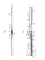
図1(a)(b)は、それぞれワイパブレード11の平面図及び正面図である。なお、図1(b)では、一部の縦断面を併せて図示している。同図に示すように、ワイパブレード11は、レバー12と、レバー12に固定されたフィン部材13と、これらレバー12及びフィン部材13に保持されたブレードラバー14と、ブレードラバー14に嵌入されたバッキング15とを備えている。このワイパブレード11は、ワイパアーム16の先端に回動可能に連結され、ワイパアーム16により払拭面に向けて付勢されるようになっている。ワイパアーム16は、その基端がワイパ装置の駆動源(図示せず)によって往復回動される図示しないピボットシャフトに固定され、ピボットシャフトと共にワイパアーム16が往復回動することにより、ワイパブレード11によって払拭面が払拭される。
DESCRIPTION OF EXEMPLARY EMBODIMENTS Hereinafter, an embodiment of the invention will be described with reference to the drawings.
FIGS. 1A and 1B are a plan view and a front view of the
図2は、図1(a)のA−A線に沿った断面図であり、図3は、図2のB−B線に沿った断面図である。また、図4は、フィン部材13を除いたワイパブレード11を示す正面図である。なお、図4では、便宜的にブレードラバー14の長手方向に対して高さ方向を強調・拡大して図示している。
2 is a cross-sectional view taken along line AA in FIG. 1A, and FIG. 3 is a cross-sectional view taken along line BB in FIG. FIG. 4 is a front view showing the
図1及び図4に示すように、前記レバー12は、ホルダ部21と、ホルダ部21から前記ブレードラバー14の長手方向両側に向けて延出形成されたアーム部22と、アーム部22の先端部に設けられた保持部23とが一体的に設けられた構成を有している。そして、ワイパブレード11は、レバー12のホルダ部21においてワイパアーム16に回動可能に連結されている。
As shown in FIGS. 1 and 4, the
詳述すると、ホルダ部21は、幅方向(図3の左右方向)に離隔されてブレードラバー14から離反する高さ方向(図3の上方向)に立設された略長方形の一対の壁部21aを有している。そして、図2に示すように、ホルダ部21には、これら両壁部21a間を連絡する回動軸17により回動可能に支持された連結部材18が設けられている。一方、ワイパアーム16の先端は略U字状に曲成されたUフックを有している。ワイパブレード11は、ホルダ部21において連結部材18にワイパアーム16のUフックが連結されることで同ワイパアーム16に回動可能に連結される。
More specifically, the
図5にレバー12の斜視図を示すように、レバー12のアーム部22は、各壁部21aの基端側において同壁部21aに連続してブレードラバー14の長手方向に延びる側壁部22aと、これら両側壁部22aを連絡する蓋壁部22bとを有して断面略U字状に形成されている。そして、図4に示すように、上記アーム部22(側壁部22a)は、先端側に向かってブレードラバー14側の高さ方向(図4の下方向)にも延出形成されている。従って、アーム部22と前記ブレードラバー14との間には、アーム部22の基端側に向かって高さ方向に広がる空隙部Sが形成されている。この空隙部Sは、払拭動作に伴うブレードラバー14の湾曲時の突出を許容するための空間である。なお、幅方向に離隔されたホルダ部21の一対の壁部21aは、これに連続するアーム部22の側壁部22a及び蓋壁部22bとともに一体化されている。
As shown in the perspective view of the
図4に示すように、レバー12の保持部23は、各アーム部22の先端部に形成されている。そして、図6に図4のC−C線に沿った断面図で示すように、保持部23の先端部には、幅方向(図6の左右方向)に対向する内側に略直角で屈曲された保持爪23aが形成されている。レバー12は、保持部23の保持爪23aが前記ブレードラバー14の後述する取付部28と係合することで前記バッキング15ともどもブレードラバー14を保持する。
As shown in FIG. 4, the holding
図1に示すように、前記フィン部材13は、長手方向においてブレードラバー14よりも若干長い長さを有して、例えば、ゴム材またはエラストマー材などの弾性材料、好ましくはブレードラバーと同等もしくはそれ以下の弾性を有する(それよりも柔軟性を有する)弾性材料にて形成されている。このフィン部材13は、レバー12及びブレードラバー14の反払拭面側(図1(b)の上側)を包囲する態様で同レバー12に固定されている。
As shown in FIG. 1, the
詳述すると、フィン部材13の長手方向の中央部には、前記レバー12のホルダ部21が挿入されてこれが収容配置される収容孔13aが形成されている。そして、フィン部材13には、この収容孔13aからそれぞれ前記各アーム部22の側壁部22a及び蓋壁部22bに対応して断面略U字状に凹設された第1収容溝13bと、更に第1収容溝13bに連続してブレードラバー14の長手方向先端部まで断面略U字状に凹設された第2収容溝13cとが形成されている。フィン部材13は、収容孔13aにホルダ部21が挿入・収容される状態で、蓋壁部22b及び第1収容溝13b間が、例えば接着剤で接合されることでレバー12に固定される。
More specifically, an
図7に図1(b)のD−D線に沿った断面図を示すように、上記第2収容溝13cを形成する側壁部の先端部には、幅方向(図7の左右方向)に対向する内側に略直角で屈曲された係合片13dが長手方向の略全体に亘って形成されている。フィン部材13は、この係合片13dが前記ブレードラバー14と係合する後述するバッキング用溝28bを含む取付部28が第2収容溝13c内に配置されることになるので、前記バッキング15の外部への露出が防止される。
As shown in a cross-sectional view along the line D-D in FIG. 1B, FIG. 7 shows a width direction (left-right direction in FIG. 7) at the front end of the side wall portion that forms the
また、図1に示すように、フィン部材13には、複数(ここでは、長手方向各側において3個ずつ)のグリッパ24が間隔をおいて固定されている。これらグリッパ24は、レバー12の保持部23とブレードラバー14の両先端部14b,14cとの間の追従端部14d部分に設けられている(図4参照)。
Further, as shown in FIG. 1, a plurality of grippers 24 (here, three on each side in the longitudinal direction) are fixed to the
詳述すると、図8に図1(b)のE−E線に沿った断面図を示すように、フィン部材13には、上記第2収容溝13cを形成する内壁面から所定深さだけ凹設された断面略U字状の収容凹部13eが形成されている。この収容凹部13eの形成に伴い当該位置での上記係合片13dは除かれている。そして、この収容凹部13eには、その内壁面に沿って断面略U字状に形成されたグリッパ24が、例えば接着剤で接合・固定されている。このグリッパ24の側壁部の先端部には幅方向(図8の左右方向)に対向して内側に略直角に屈曲された保持爪24aが形成されている。フィン部材13に固定されたグリッパ24は、その内壁面の形状が第2収容溝13cの内壁面の形状に連続するように、すなわち第2収容溝13cの内壁面に対してグリッパ24の内壁面が略面一となるように形成されている。フィン部材13に固定されたグリッパ24は、保持爪24aが前記ブレードラバー14と係合することで前記バッキング15ともどもブレードラバー14を保持する。
More specifically, as shown in FIG. 8 which is a cross-sectional view taken along line EE of FIG. 1B, the
図1、図7及び図8に示すように、フィン部材13は、払拭面側に上記第1及び第2収容溝13b,13cを有し、反払拭面側には横断面形状が略三角形状をなすフィン部25を有している。すなわち、フィン部25は、収容孔13a(ホルダ部21)に対してフィン部材13の長手方向両側にそれぞれ配置されている。このフィン部25は、車両の走行風を受けることにより受ける抗力を分散させ、かつ、その分力をブレードラバー14に直接作用せしめて浮き上がりを防止するため、払拭面26(図7参照)に対して鋭角αをなす凹面状の傾斜面25aを有している。
As shown in FIGS. 1, 7 and 8, the
図3に示すように、ホルダ部21の両側に配置された各フィン部25は、上記収容孔13aの内壁面を形成する被覆部27によって互いに連結されている。この被覆部27は、ホルダ部21よりも払拭面側に突出する態様で同ホルダ部21(壁部21a)の外側の側面21bを被覆している。
As shown in FIG. 3, the
なお、図1に示すように、フィン部25の長手方向先端部には、前記第2収容溝13cの内壁面に連続して払拭面側に突出するストッパ壁25bが形成されている。このストッパ壁25bは、保持したブレードラバー14が当接することでその長手方向の移動を規制する。
In addition, as shown in FIG. 1, the
図3に示すように、レバー12及びフィン部材13(グリッパ24)に取り付けられるブレードラバー14はゴム材からなり、取付部28及びこれとネック部14aを介して連結された払拭部29を有して長尺状に成型されている。ブレードラバー14は、取付部28においてレバー12及びフィン部材13(グリッパ24)に保持され、払拭部29において払拭面26を払拭する。
As shown in FIG. 3, the
取付部28には、その各外側面28aから対向する幅方向(図3の左右方向)に凹設されたバッキング用溝28b及び保持用溝28cが形成されている。これらバッキング用溝28b及び保持用溝28cは、ブレードラバー14の長手方向に沿って延びるように形成されている。従って、取付部28の横断面は、上下2箇所において括れた形状となっている。バッキング用溝28bは、高さ方向において保持用溝28cよりもレバー12(及びフィン部材13)側(図3において上側)に配置されている。
The mounting
バッキング用溝28bは、前記バッキング15を嵌入するためのものである。なお、図4に示すように、バッキング用溝28bの長手方向両端部は、幅方向から嵌入されるバッキング15の長手方向の移動を規制するための規制面28dとなっている。
The
また、保持用溝28cは、取付部28が前記レバー12等に保持された状態において、レバー12(保持部23)の保持爪23a及びグリッパ24の保持爪24aが挿入される配置となっている。すなわち、図6に示すように、取付部28の両外側面28a間が幅寸法W1を有するとすると、レバー12の保持爪23aの対向する先端間の幅寸法W2はこの幅寸法W1よりも小さくなるように設定されている。また、図8に示すように、グリッパ24の保持爪24aの対向する先端間の幅寸法W3も上記幅寸法W1よりも小さくなるように設定されている。そして、これら保持爪23a,24aは、高さ方向において保持用溝28cに対応する位置に形成されている。ブレードラバー14は、保持用溝28cに挿入された保持爪23a,24aによってレバー12及びグリッパ24に保持される。なお、上記保持爪23a,24aは、保持用溝28cに挿入されるのみであるため、レバー12に対するブレードラバー14の特に長手方向への摺動を規制するものではない。つまり、レバー12の両保持部23間に位置するブレードラバー14の実際の実長さが、払拭面に追従することによって湾曲状態が変化し、その両保持部23間の実長さも変化するため、その実長さの変化量がレバー12に対するブレードラバー14の長手方向への摺動によって吸収される。従って、上記長手方向への摺動によって、払拭動作に伴うブレードラバー14の弾性追従が許容される。
The holding
さらに、上記保持用溝28cは、取付部28が前記レバー12等に保持された状態において、前記係合片13dも挿入される配置となっている。すなわち、図7に示すように、フィン部材13の係合片13dの対向する先端間が幅寸法W4も、上記幅寸法W1よりも小さくなるように設定されている。そして、係合片13dは、高さ方向において保持用溝28cに対応する位置に形成されている。保持用溝28cに係合片13dが挿入されることにより、ブレードラバー14はフィン部材13により取付部28の略全体が覆われると共に、これに嵌入されたバッキング15は外部への露出が防止されて閉塞される。
Further, the holding
なお、図9に図4のF−F線に沿った断面図を示すように、各保持用溝28cには、係止部30が形成されている。この係止部30は、一方の保持部23(保持爪23a)の両側に対応して配置されている。また、ブレードラバー14(保持用溝28c)の長手方向における係止部30間の距離bは、一方の保持爪23aの幅寸法aよりも大きく設定され、所定の遊び量(b−a)を有している。
As shown in FIG. 9 which is a cross-sectional view taken along the line FF in FIG. 4, a locking
各係止部30は、保持爪23a側(保持位置側)に向かって幅方向に徐々に隆起する傾斜部30aを有している。そして、係止部30の保持爪23aに対向する端面は、幅方向にステップ状に隆起する規制面30bを形成している。この規制面30bは、ブレードラバー14の保持位置からのレバー12(保持爪23a)の長手方向への移動を規制するためのものである。すなわち、係止部30が規制面30bにおいて幅寸法W5を有しているとすると、この幅寸法W5は前記保持爪23aの対向する先端間の幅寸法W2よりも大きくなるように設定されている。これにより、上記保持位置においてレバー12が上記長手方向端部側に移動しようとすると、遊び量(b−a)だけ移動可能であるが、その保持部23(保持爪23a)が係止部30に係止されてブレードラバー14のレバー12からの抜けが防止される。なお、レバー12をブレードラバー14の保持位置へと組付ける際には、ブレードラバー14の端部側から保持用溝28cに保持爪23aを挿入した状態で長手方向に移動させる。この際、保持爪23aは、ゴム材からなる係止部30を弾性変形させながら傾斜部30aに沿って徐々に移動して規制面30bを通過し、両規制面30b間においてブレードラバー14の抜けが防止される。
Each locking
ブレードラバー14の払拭部29は、縦断面略三角形状に形成されており、ネック部14aによって取付部28に対し傾動反転自在に連結されている。
前記バッキング15は、バネ性を有する金属材料(バネ材)からなり、細長い板状に形成されている。また、バッキング15は、自然状態(無負荷状態)において払拭面26の曲率よりも小さい曲率(払拭面26の湾曲半径よりも小さな湾曲半径)を有して長手方向中央部が反払拭面側に向けて凸状となる湾曲形状に形成されている。このバッキング15は、各バッキング用溝28bにそれぞれ完全に収まる態様で嵌入されている。すなわち、図3に示すように、バッキング15及びバッキング用溝28bの溝深さがそれぞれ幅寸法W6,W7を有するとすると、バッキング15の幅寸法W6はこの幅寸法W7以下に設定されている。
The wiping
The
バッキング用溝28bにバッキング15を嵌入すると、バッキング15の形状に合わせてワイパブレード11が湾曲変形する。また、バッキング15は所定の剛性及びバネ性を有しているので、払拭時にワイパアーム16により押圧力が加わると、ブレードラバー14は払拭面26の曲率に合わせて弾性変形する。
When the
ここで、ブレードラバー14の長手方向におけるレバー12の保持部23(レバー12の保持位置)の配置設定について説明すると、保持部23は同長手方向を略3等分する態様で配置されている。すなわち、図4に示すように、ブレードラバー14が長手方向に長さLを有しているとする。そして、レバー12の保持部23が上記長手方向に長さL1だけ離間されているとすると、各保持部23の保持爪23aの先端からブレードラバー14の長手方向(図4の左側及び右側)先端部14b,14cまでの各長さL2,L3は、長さL1と同等に設定されている。つまり、ブレードラバー14は、保持部23(保持爪23a)により長手方向において均等となる中間部で保持されている。なお、各保持部23の保持爪23aの先端からバッキング15が嵌入されたブレードラバー14の各先端部14b,14cまでの範囲を特に追従端部14dという。
Here, the arrangement setting of the holding portion 23 (holding position of the lever 12) of the
また、上記保持部23は、ブレードラバー14(払拭部29)による払拭動作に伴い変化する払拭面26の曲率変化の少ない位置にそれぞれ設定されている。詳述すると、図10(a)に車両に搭載されたワイパブレード11の払拭動作の模式図にて示したように、ワイパブレード11による払拭動作に伴いその一側(図10の左側)先端部は、動作点P1から動作点P2までの間を変位する。同様に、ワイパブレード11の他側(図10の右側)先端部は、動作点P3から動作点P4までの間を変位する。これら動作点P1〜P4の軌跡は、一般に助手席側に配置されたワイパブレードの軌跡に相当する。このとき、図10(b)に払拭動作に伴い変化する払拭面26の曲率変化を示したように、動作点P1,P2側では上記曲率変化が小さいのに対し、動作点P3,P4側では同曲率変化が著しく大きくなっている。それに伴って、動作点P3とP4との間の変位量も大きくなる。従って、レバー12の保持部23は、上記ワイパブレード11の他側先端部の近傍を避けた長手方向中間部、即ち払拭動作に伴い変化する払拭面26の曲率変化の少ない位置に配置されている。換言すると、レバー12の保持部23が上記ワイパブレード11の先端部近傍に配置される場合には、従来技術と同様の構成に近似し、追従端部14dが構成されなくなり、しかも、払拭面26の曲率変化に対するブレードラバー14の弾性追従が保持部23により妨げられ、当該位置における払拭性に著しい影響を及ぼすことになる。
Moreover, the said holding |
次に、ワイパブレード11の組付け態様について総括的に説明する。図1(b)に示すように、フィン部材13は、収容孔13aにホルダ部21が挿入・収容される状態でアーム部22と接合され、レバー12に固定される。このとき、図8に示すように、フィン部材13には、前記収容凹部13eにおいてグリッパ24が接合されている。この状態では、フィン部材13の第1収容溝13b及び第2収容溝13c内にそれぞれレバー12(保持部23)の保持爪23a及びグリッパ24の保持爪24aがブレードラバー14と係合しうるように現出している。
Next, the assembly mode of the
一方、ブレードラバー14の各バッキング用溝28b内に予めバッキング15を嵌入しておく。この状態で、フィン部材13の長手方向いずれかの先端側から同方向に沿ってブレードラバー14を係止部30が設けられていない側の端部から保持用溝28cに上記保持爪24a,23aを順次挿入していき、同ブレードラバー14をレバー12による保持位置へと移動させる。このとき、保持部23の両保持爪23aが、前記係止部30を通過することで上記保持位置に位置決めされ、この状態でブレードラバー14はレバー12及びフィン部材13(グリッパ24)に保持される。なお、保持されたブレードラバー14は、フィン部材13のストッパ壁25bに当接させることでその長手方向への抜けを規制するようにしてもよい。また、ブレードラバー14の保持用溝28cに上記保持爪24a,23aが挿入されることで、図6及び図8に示すように、バッキング用溝28bの開放側(幅方向外側)はレバー12の保持部23及びグリッパ24により部分的に塞がれる。従って、バッキング用溝28bに嵌入されたバッキング15は、これら保持部23及びグリッパ24によって抜け止めされる。
On the other hand, the
さらに、ブレードラバー14の保持用溝28cに前記係合片13dが挿入されることで、図7に示すように、バッキング用溝28bの残りの開口部は塞がれ、同様にバッキング15が抜け止めされると共に外部への露出も防止される。
Further, as the
以上詳述したように、本実施形態によれば、以下に示す効果が得られるようになる。
(1)本実施形態では、ワイパアーム16の押圧力を単一のレバー12を介してブレードラバー14に付与する形態であるため、所謂トーナメント式に比べてワイパブレード11の高さを抑えることができる。
As described above in detail, according to the present embodiment, the following effects can be obtained.
(1) In this embodiment, since the pressing force of the
また、レバー12のアーム部22によりワイパアーム16の押圧力をブレードラバー14の長手方向に分配し中央部への過度な押圧力の集中を低減することができる。このため、払拭時に中央部にすじが残る拭き残しを抑制して良好な払拭性を確保することができる。
Further, the pressing force of the
さらに、レバー12の保持部23は、ブレードラバー14の長手方向両先端部14b,14cと前記ホルダ部21との間の中間部にそれぞれ配置したことにより、ワイパブレード11の端部においてはバッキング15の自由変形が許容される。そして、バッキング用溝28bにバッキング15が嵌入されたブレードラバー14は、前記レバー12の保持部23からブレードラバー14の長手方向両先端部14b,14cまでの間において払拭面26方向に自由に弾性追従する追従端部14dを有する。このため、ワイパブレード11の端部ではバッキング15によるブレードラバー14の払拭面26に対する弾性追従がレバー12によって妨げられることはなく、良好な払拭性を確保することができる。
Further, the holding
また、ホルダ部21からアーム部22を介してブレードラバー14の長手方向に延出させた保持部23によりブレードラバー14を保持したことで、弾性追従させるブレードラバー14の端部(追従端部14d)の長さを必要以上に長くすることがない。これにより、弾性追従を妨げることなくブレードラバー14の端部のねじれ剛性(ブレードラバー14の長手方向を軸線とするねじり方向の剛性)を向上させることができる。これにより、所謂レバーレス式に比べて長手方向により長いブレードラバー(ワイパブレード)であっても、上記弾性追従性及びねじれ剛性の向上により払拭面に対するブレードラバー14の姿勢(アタックアングル)が確保されるため、円滑な払拭動作と良好な払拭性を実現できる。
Further, the
(2)本実施形態では、ワイパアーム16の押圧力はレバー12のアーム部22により分配され、ブレードラバー14の長手方向全長を略3等分する2位置において2つの保持部23よりブレードラバー14に付与される。これにより、ブレードラバー14の長手方向全長にわたって払拭面26に対する押圧力が過度に集中する部位がなくなり、同押圧力をほぼ均一な分布とすることができる。
(2) In this embodiment, the pressing force of the
(3)本実施形態では、保持部23においてバッキング15の自由変形が一部規制されてしまうが、保持部23からワイパブレード11の両先端部にかけては自由な追従変形が許容されているため、もともと払拭性への影響が小さい。しかも、払拭動作に伴い変化する払拭面26の曲率変化の少ない位置に保持部23がそれぞれ配置設定されていることで、当該位置における湾曲追従に必要な追従量も小さく、払拭性への影響を低減することができる。
(3) In the present embodiment, the free deformation of the
(4)本実施形態では、フィン部材13は、高速走行時の走行風を傾斜面で受けてワイパアーム16の押圧力を補完し、ブレードラバー14の浮き上がりを防止する。このとき、フィン部材13は、ブレードラバー14を保持するレバー12及びグリッパ24に固定され、ブレードラバー14の長手方向に沿ってホルダ部21の両側に配置されているので、ブレードラバー14の長手方向全体にわたって上記押圧力を補完することができる。
(4) In the present embodiment, the
(5)本実施形態では、バッキング用溝28bなどが形成されるブレードラバー14の取付部28の少なくとも一部がフィン部材13の第1及び第2収容溝13b,13c内に収容される。従って、ワイパブレード11の高さ寸法を低減することができると共にワイパブレード11の側面側からの見栄えも向上することができる。例えば、バッキング用溝28bの開放側がフィン部材13によって覆い隠される。これにより、バッキング15は外部に露出しないので、金属材料であるバッキング15をブレードラバー14と同じ色、一般には防眩色である黒色に塗装しなくともワイパブレード11の美観を損なうことはない。さらに、バッキング用溝28bが第1及び第2収容溝13b,13c内に配置されるように取付部28を収容したことで、付着した水滴が凍結しやすいバネ材(一般に金属材)のバッキング15を被覆し、水滴の凍結を防止することができる。また、バッキング15のバッキング用溝28bからのはみ出しを防止すると共に、バッキング15のエッジ部分も保護することができる。
(5) In the present embodiment, at least a part of the
(6)本実施形態では、フィン部25を互いに連結する被覆部27が、レバー12のホルダ部21(壁部21a)の両側面21bを被覆するため、ワイパブレード11がフィン部材13により一体感を有するデザインとなって外観を向上することができる。
(6) In the present embodiment, since the covering
(7)本実施形態では、フィン部材13に対しブレードラバー14が長手方向に移動することを防止するための係止構造を設けなくても、ブレードラバー14がフィン部材13のストッパ壁25bに当接することで、ブレードラバー14の長手方向への相対移動(抜けだし)を防止することができる。
(7) In the present embodiment, the
(8)本実施形態では、グリッパ24によりバッキング15とブレードラバー14とが共に保持されることで、バッキング15の先端部のバッキング用溝28bからのはみ出しを防止して、バッキング15によるブレードラバー14の払拭面26に対する弾性追従をより確実にすることができる。また、グリッパ24がフィン部材13に固定されたことで、フィン部材13による上記ワイパアーム16の押圧力の補完を、ブレードラバー14の追従端部14dにおいてもレバーを介することなく直接的に行うことができる。
(8) In the present embodiment, the
(9)本実施形態では、ブレードラバー14の払拭面26に対する弾性追従の際に、その長手方向中央部、すなわちレバー12のホルダ部21の部位にて頂点をなす湾曲となる。この湾曲時の頂点の突出をアーム部22の側壁部22aとブレードラバー14の上面14e(図4参照)との間に形成した空隙部Sにて許容することで、バッキング15を含むブレードラバー14の弾性追従性をより向上することができる。
(9) In the present embodiment, when the
なお、本発明の実施の形態は上記実施形態に限定されるものではなく、次のように変更してもよい。
・前記実施形態において、レバーの保持部は、各アーム部22の先端部に設けられる1個(保持部23)に限定されるものではない。すなわち、図11に示すレバー31のように、各アーム部22においてホルダ部21と保持部23との間に、保持部23に準じた形状の保持部32をさらに設けてもよい。この場合であっても、保持部32はレバー31に対するブレードラバー14の長手方向への摺動を規制するものではない。また、各アーム部22に設けられる保持部32は複数であってもよい。さらに、両アーム部22に設けられる保持部32の個数は、互いに異なっていてもよい。要は、少なくとも各アーム部22の先端部に保持部を備えた形状であればよい。
In addition, embodiment of this invention is not limited to the said embodiment, You may change as follows.
In the above-described embodiment, the holding portion of the lever is not limited to one (holding portion 23) provided at the distal end portion of each
・前記実施形態において、ブレードラバー14を保持する保持部23の一方をブレードラバー14に固定してもよい。例えば、図12に示すように、一側(図12の右側)の保持部23をブレードラバー14に固定する。この場合、払拭動作に伴うブレードラバー14の弾性追従では、固定された一側(図12の右側)の保持部23を基準に長手方向に摺動する。具体的には、ブレードラバー14及びこれに嵌入されたバッキング15が、自然状態において両保持部23間で実際の実長さL11を有するとする。この状態で、ワイパブレード11(ブレードラバー14)が払拭面26に対して押圧されると、弾性追従に伴いブレードラバー14は、固定された一側(図12の右側)の保持部23を基準に他側の保持部23から突出するように長手方向に摺動する。このとき、ブレードラバー14及びこれに嵌入されたバッキング15は、両保持部23間の実長さL12(<L11)となるように弾性変形し、弾性追従を妨げない。
In the embodiment, one of the holding
・前記実施形態においては、レバー12のアーム部22に接合する態様でフィン部材13をレバー12に固定した。これに対して、図13に示す態様でレバー12にフィン部材13を固定してもよい。すなわち、アーム部22の蓋壁部22bには、その高さ方向(図13の上下方向)に貫通する係合孔36が形成されている。一方、フィン部材13には、上記係合孔36に対応して第1収容溝13bから突出する係合突部37が形成されている。この係合突部37は、係合孔36の内径と同等の外径を有する軸部37aと、同軸部37aの先端部において径方向外側に突出する係止部37bとを備えている。フィン部材13は、係止部37bが蓋壁部22bに係止されることで抜け止めされ、レバー12に固定される。なお、フィン部材13とグリッパ24との固定においても、上記形態を採用してもよい。
In the above embodiment, the
・前記実施形態においては、フィン部材13の各フィン部25にグリッパ24を固定したが、一方のフィン部25にのみ固定するようにしてもよい。この場合、ワイパアーム16の立てるとき(ロックバック状態とするとき)の移動距離が小さい後端側のフィン部25に固定することで、ワイパアーム16を下ろすときの衝撃によってグリッパ24が外れるといった現象を防止することができる。
In the embodiment, the
・前記実施形態において、インサート成形にてフィン部材13をレバー12及びグリッパ24に固定してもよい。
・前記実施形態において、保持部23は、ホルダ部21とブレードラバー14の先端部14b,14cとの各中間部に配置されるのであれば、その配置は任意である。各保持部23は、ホルダ部21を中心とする対称配置であってもなくてもよい。
In the embodiment, the
-In the said embodiment, if the holding |
・前記実施形態において、ホルダ部21からブレードラバー14の長手方向両側に形成される各アーム部22の延出長は、互いに同等であっても異なっていてもよい。すなわち、レバー12は、ホルダ部21を中心とする対称構造であってもなくてもよい。
-In the said embodiment, the extension length of each
・前記実施形態においては、レバー12の保持部23により取付部28においてブレードラバー14を保持する構造とした。これに対し、例えばバッキング用溝28bからこれに嵌入されるバッキング15の一部を幅方向に現出させ、当該現出部をレバー12の保持部23により保持してもよい。この場合、ブレードラバー14はバッキング15を介してレバー12に支持されることになる。
In the embodiment, the
・前記実施形態において、レバー12のホルダ部21、アーム部22及び保持部23は、それぞれ別体で成形して別途溶接などで接合してもよい。
・前記実施形態においては、ブレードラバー14は、ゴム材により形成されていたが、弾性変形可能な材料(弾性材料)であれば、ゴム材に限定されるものではない。
-In the said embodiment, the
In the above-described embodiment, the
・前記実施形態においては、レバー12を包囲する態様で同レバー12にフィン部材13を固定していたが、このフィン部材13を省略し、レバー12を露出させる構成してもよい。
In the above-described embodiment, the
例えば、図14〜図16に示すワイパブレード11aのレバー12aは、前記実施形態と同様に、ワイパアーム16に回動可能に連結されるホルダ部21と、ホルダ部21からブレードラバー14の長手方向両側に向けて延出形成されたアーム部22と、アーム部22の先端部に設けられた保持部23とが一体的に設けられ、該保持部23にてバッキング15ともどもブレードラバー14を保持している。このレバー12aにおいても、アーム部22及びホルダ部21とブレードラバー14との間に、高さ方向に広がる空隙部Sが形成されており、保持部23が、長手方向を略3等分する位置に配置されている。また、このレバー12aのアーム部22は、下側(ブレードラバー14側)が開口する断面略V字状をなしており、先端部に向かうほど(保持部23に向かうほど)、高さが次第に低くなる形状をなしている。このアーム部22の幅方向一側には、長手方向全体にわたって、車両の走行風を受けるとブレードラバー14を払拭面26側に押し付ける力が生じるように該払拭面26に対して傾斜する凹面状の傾斜面22dを有したフィン部22cが一体に形成されている。そして、このような構成のレバー12aは、金属板材に対してプレス加工を施して形成されている。また、ブレードラバー14の両端部には、該ブレードラバー14からバッキング15が脱落しないように樹脂製のキャップ40が装着されている。
For example, the
これにより、レバー12aのフィン部22cは、高速走行時の走行風を傾斜面で受けてワイパアーム(図示略)の押圧力を補完するため、レバー12a単体でも、ブレードラバー14の浮き上がりを防止できる。又、フィン部22cはレバー12aに一体に形成されるので、ワイパブレード11aの部品点数の減少に貢献できる。又、ホルダ部21からブレードラバー14の長手方向両側に向けて延びるアーム部22にフィン部22cが一体に形成されるので、外観上のデザインを良好に保ちながらフィン部22cを形成することができる。
As a result, the
又、図17〜図19に示すワイパブレード11bのブレードラバー14は、その上面(払拭部29とは反対側の面)に対して、車両の走行風を受けるとブレードラバー14を払拭面26側に押し付ける力を生じさせる凹面状の傾斜面14gを有するフィン部14fが一体に形成されている。フィン部14fは、レバー12aの保持部23より長手方向内側の所定部位から立設されており、長手方向端部側に向かって高さが次第に低くなる形状をなしている。また、これに応じて、レバー12aのアーム部22の先端部側(保持部23側)の形状が変更され、保持部23においてもブレードラバー14のフィン部14fの形状に応じて上方に凹設される凹設部23bが形成されている。つまり、この凹設部23bにブレードラバー14のフィン部14fの基端部分が収容されて、レバー12aのアーム部22(フィン部22c)からブレードラバー14のフィン部14fに形状が連続するようにしている。
Further, the
これにより、レバー12aのフィン部22cとブレードラバー14のフィン部14fとが協働することで、走行風を受けることによるワイパブレード11bの押圧力を増大させることができる。しかも、ワイパブレード11bの部品点数の増加させない。
Thus, the pressing force of the
尚、図14〜図19のレバー12aでは、アーム部22にフィン部22cを形成したが、アーム部22以外、例えば、ホルダ部21の一側面にフィン部を形成したり、アーム部22(保持部23)からブレードラバー14の端部側に向かってさらに延設し、その延設部分にフィン部を形成してもよい。また、これらを組み合わせてフィン部を形成してもよい。
14 to 19, the
11,11a,11b…ワイパブレード、12,12a…レバー、13…フィン部材、13b,13c…収容部を形成する第1及び第2収容溝、14…ブレードラバー、14b,14c…先端部、14d…追従端部、15…バッキング、16…ワイパアーム、21…ホルダ部、22…アーム部、22c…フィン部、22d…傾斜面、23…保持部、24…保持部材としてのグリッパ、25…フィン部、25a…傾斜面、25b…ストッパ壁、26…払拭面、27…被覆部、28…取付部、28b…バッキング用溝、29…払拭部、S…空隙部。
DESCRIPTION OF
Claims (4)
所定の剛性を有すると共に中央部が反払拭面側に向けて凸状に湾曲形成され、前記ブレードラバーの長手方向に形成されたバッキング用溝に嵌入されるバネ材からなるバッキングと、
ワイパアームが回動可能に連結されるホルダ部と、該ホルダ部から前記ブレードラバーの長手方向両側に向けて延びるとともに前記ホルダ部に一体形成されたアーム部と、該アーム部の先端部に設けられ前記ブレードラバー又は前記バッキングを保持する保持部とを有するレバーと、を備え、
前記レバーの前記保持部は、前記ブレードラバーの長手方向両先端部と前記ホルダ部との間の中間部にそれぞれ配置され、
前記レバーは、前記ホルダ部から前記アーム部が前記ブレードラバーの方向に延出形成されて、2つの前記保持部の間において前記アーム部及び前記ホルダ部と前記ブレードラバーとの間に空隙部を有するとともに、前記払拭面に対して傾斜する傾斜面を有するフィン部が各アーム部自体に一体形成されていることを特徴とするワイパブレード。 Blade rubber to wipe the wiping surface;
A backing made of a spring material having a predetermined rigidity and having a central portion curved in a convex shape toward the anti-wiping surface, and fitted into a backing groove formed in the longitudinal direction of the blade rubber;
A holder part to which the wiper arm is rotatably connected; an arm part extending from the holder part toward both sides in the longitudinal direction of the blade rubber and integrally formed with the holder part ; and a tip part of the arm part. A lever having a holding portion for holding the blade rubber or the backing, and
The holding portions of the lever are respectively disposed at intermediate portions between both longitudinal end portions of the blade rubber and the holder portion ,
In the lever, the arm portion extends from the holder portion in the direction of the blade rubber, and a gap portion is provided between the arm portion and the holder portion and the blade rubber between the two holding portions. A wiper blade characterized in that a fin portion having an inclined surface inclined with respect to the wiping surface is integrally formed on each arm portion itself .
前記レバーの前記保持部は、前記ブレードラバーの長手方向全長を略3等分する2位置にそれぞれ配置したことを特徴とするワイパブレード。 The wiper blade according to claim 1,
The wiper blade according to claim 1, wherein the holding portion of the lever is disposed at two positions that divide the entire length in the longitudinal direction of the blade rubber into approximately three equal parts.
前記レバーの前記保持部は、前記ブレードラバーの長手方向のうち、前記ブレードラバーによる払拭動作に伴い変化する前記払拭面の曲率変化の少ない位置にそれぞれ設定されていることを特徴とするワイパブレード。 The wiper blade according to claim 1 or 2,
The wiper blade according to claim 1, wherein the holding portion of the lever is set at a position in the longitudinal direction of the blade rubber where the curvature of the wiping surface changes with the wiping operation by the blade rubber.
前記バッキング用溝に前記バッキングが嵌入された前記ブレードラバーは、前記レバーの前記保持部の各々から前記ブレードラバーの長手方向両先端部までの間において前記払拭面方向に自由に弾性追従する追従端部を有することを特徴とするワイパブレード。 The wiper blade according to any one of claims 1 to 3,
The blade rubber in which the backing is inserted into the backing groove has a follow-up end that freely elastically follows in the wiping surface direction from each of the holding portions of the lever to both longitudinal ends of the blade rubber. A wiper blade having a portion.
Priority Applications (7)
| Application Number | Priority Date | Filing Date | Title |
|---|---|---|---|
| JP2004027259A JP4202940B2 (en) | 2003-06-13 | 2004-02-03 | Wiper blade |
| US10/859,084 US7526832B2 (en) | 2003-06-13 | 2004-06-03 | Wiper blade having a lever connected to wiper arm |
| FR0406383A FR2856025B1 (en) | 2003-06-13 | 2004-06-11 | WIPER BLADE WITH A LEVER CONNECTED TO THE WIPER ARM |
| DE102004028297.8A DE102004028297B4 (en) | 2003-06-13 | 2004-06-11 | Wiper blade with a lever connected to the wiper arm |
| DE102004064199.4A DE102004064199B8 (en) | 2003-06-13 | 2004-06-11 | Wiper blade with a lever connected to the wiper arm |
| KR1020040043133A KR101057120B1 (en) | 2003-06-13 | 2004-06-11 | Wiper blades with lever connected to wiper arm |
| CNB2004100592528A CN100486842C (en) | 2003-06-13 | 2004-06-14 | Wiper blade having lever connected to wiper arm |
Applications Claiming Priority (2)
| Application Number | Priority Date | Filing Date | Title |
|---|---|---|---|
| JP2003170023 | 2003-06-13 | ||
| JP2004027259A JP4202940B2 (en) | 2003-06-13 | 2004-02-03 | Wiper blade |
Publications (2)
| Publication Number | Publication Date |
|---|---|
| JP2005022632A JP2005022632A (en) | 2005-01-27 |
| JP4202940B2 true JP4202940B2 (en) | 2008-12-24 |
Family
ID=33492488
Family Applications (1)
| Application Number | Title | Priority Date | Filing Date |
|---|---|---|---|
| JP2004027259A Expired - Fee Related JP4202940B2 (en) | 2003-06-13 | 2004-02-03 | Wiper blade |
Country Status (6)
| Country | Link |
|---|---|
| US (1) | US7526832B2 (en) |
| JP (1) | JP4202940B2 (en) |
| KR (1) | KR101057120B1 (en) |
| CN (1) | CN100486842C (en) |
| DE (2) | DE102004028297B4 (en) |
| FR (1) | FR2856025B1 (en) |
Families Citing this family (43)
| Publication number | Priority date | Publication date | Assignee | Title |
|---|---|---|---|---|
| FR2364759A1 (en) * | 1976-09-21 | 1978-04-14 | Bar E Inc W | Latex emulsion coagulating appts. - in which the water and polymer are separated out in the less than full flights of a screw |
| WO2005123471A1 (en) * | 2004-06-18 | 2005-12-29 | Mitsuba Corporation | Wiper blade |
| JP2007118621A (en) * | 2004-06-18 | 2007-05-17 | Mitsuba Corp | Wiper device |
| DE102005019389A1 (en) * | 2005-04-28 | 2006-11-02 | Robert Bosch Gmbh | Wiper blade for vehicle window pane has covering cap, which comprises opening or recess for angular end of clip, on the side of cap opposing rubber profiled element in the region of connection element |
| US7350259B2 (en) * | 2005-07-28 | 2008-04-01 | Tenneco Automotive Operating Company Inc. | Relative axial translation prevention system for wiper blade assemblies |
| DE602006007443D1 (en) * | 2006-05-08 | 2009-08-06 | Federal Mogul Sa | wiper device |
| JP5049622B2 (en) * | 2007-03-26 | 2012-10-17 | 株式会社ミツバ | Wiper blade |
| FR2923785B1 (en) * | 2007-11-19 | 2009-12-25 | Valeo Systemes Dessuyage | WIPER BLADE FOR VEHICLE WINDOWS. |
| ES2701435T3 (en) * | 2009-08-27 | 2019-02-22 | Trico Products Corp | Windshield wiper assembly |
| JP5584012B2 (en) * | 2010-05-12 | 2014-09-03 | アスモ株式会社 | Wiper blade |
| US8898850B2 (en) | 2010-05-31 | 2014-12-02 | Asmo Co., Ltd. | Wiper blade |
| JP5576247B2 (en) * | 2010-11-15 | 2014-08-20 | アスモ株式会社 | Wiper blade |
| USD706200S1 (en) | 2010-09-22 | 2014-06-03 | Pylon Manufacturing Corporation | Windshield wiper cover |
| WO2012063650A1 (en) | 2010-11-10 | 2012-05-18 | アスモ 株式会社 | Wiper blade |
| DE102010062899A1 (en) * | 2010-12-13 | 2012-06-14 | Robert Bosch Gmbh | Wiper blade device |
| JP5780685B2 (en) * | 2011-02-03 | 2015-09-16 | フェデラル−モグル エス.エー.Federal−Mogul.S.A. | Windshield wiper device |
| USD685712S1 (en) | 2011-03-23 | 2013-07-09 | Kcw Corporation | Wiper |
| US9457768B2 (en) | 2011-04-21 | 2016-10-04 | Pylon Manufacturing Corp. | Vortex damping wiper blade |
| US9174609B2 (en) | 2011-04-21 | 2015-11-03 | Pylon Manufacturing Corp. | Wiper blade with cover |
| US9174611B2 (en) | 2011-07-28 | 2015-11-03 | Pylon Manufacturing Corp. | Windshield wiper adapter, connector and assembly |
| MX347284B (en) | 2011-07-29 | 2017-04-21 | Pylon Mfg Corp | Windshield wiper connector. |
| US8806700B2 (en) | 2011-07-29 | 2014-08-19 | Pylon Manufacturing Corporation | Wiper blade connector |
| US9108595B2 (en) | 2011-07-29 | 2015-08-18 | Pylon Manufacturing Corporation | Windshield wiper connector |
| EP2750939B1 (en) * | 2011-08-31 | 2019-03-06 | Federal-Mogul S.a. | Windscreen wiper device |
| KR102005798B1 (en) | 2011-12-14 | 2019-07-31 | 페더럴-모걸 엘엘씨 | Windscreen wiper device |
| US10723322B2 (en) | 2012-02-24 | 2020-07-28 | Pylon Manufacturing Corp. | Wiper blade with cover |
| CA2865292C (en) | 2012-02-24 | 2018-03-13 | Pylon Manufacturing Corp. | Wiper blade |
| US20130219649A1 (en) | 2012-02-24 | 2013-08-29 | Pylon Manufacturing Corp. | Wiper blade |
| US10829092B2 (en) | 2012-09-24 | 2020-11-10 | Pylon Manufacturing Corp. | Wiper blade with modular mounting base |
| WO2014089755A1 (en) * | 2012-12-11 | 2014-06-19 | Shen Qinghuai | Windscreen wiper strip support and windscreen wiper blade having same |
| US10166951B2 (en) | 2013-03-15 | 2019-01-01 | Pylon Manufacturing Corp. | Windshield wiper connector |
| US9505380B2 (en) | 2014-03-07 | 2016-11-29 | Pylon Manufacturing Corp. | Windshield wiper connector and assembly |
| US9539987B2 (en) | 2014-04-01 | 2017-01-10 | Trico Products Corporation | Wiper adapter and wiper assembly incorporating the same |
| US9434355B2 (en) | 2014-04-01 | 2016-09-06 | Trico Products Corporation | Wiper adapter and wiper assembly incorporating the same |
| USD777079S1 (en) | 2014-10-03 | 2017-01-24 | Pylon Manufacturing Corp. | Wiper blade frame |
| USD787308S1 (en) | 2014-10-03 | 2017-05-23 | Pylon Manufacturing Corp. | Wiper blade package |
| WO2017075066A1 (en) | 2015-10-26 | 2017-05-04 | Pylon Manufacturing Corp. | Wiper blade |
| US10513246B2 (en) | 2016-05-19 | 2019-12-24 | Pylon Manufacturing Corp. | Windshield wiper connector |
| US11040705B2 (en) | 2016-05-19 | 2021-06-22 | Pylon Manufacturing Corp. | Windshield wiper connector |
| CN109311450A (en) | 2016-05-19 | 2019-02-05 | 电缆塔制造有限公司 | Windscreen wiper connector |
| EP3458315B1 (en) | 2016-05-19 | 2021-09-08 | Pylon Manufacturing Corp. | Windshield wiper blade |
| US10661759B2 (en) | 2016-05-19 | 2020-05-26 | Pylon Manufacturing Corporation | Windshield wiper connector |
| KR102052913B1 (en) * | 2017-12-14 | 2019-12-11 | 주식회사 링콘테크놀로지 | Sludge collector |
Family Cites Families (24)
| Publication number | Priority date | Publication date | Assignee | Title |
|---|---|---|---|---|
| GB678198A (en) | 1946-01-29 | 1952-08-27 | Productive Inventions Inc | Improvements in and relating to means for connecting windscreen wipers |
| FR2181101A5 (en) * | 1972-04-17 | 1973-11-30 | Sev Marchal | |
| GB1438568A (en) | 1972-09-09 | 1976-06-09 | Fister Snc Di Bosso Giacomo C | Windshield wiper blade |
| FR2258990B1 (en) * | 1974-01-30 | 1978-03-17 | Journee Paul | |
| US3978543A (en) * | 1974-04-16 | 1976-09-07 | Magnatex Limited | Windscreen wipers |
| IT1118510B (en) * | 1979-03-23 | 1986-03-03 | Apman Spa | TERGIORISTALLO SPATULA |
| FR2530562B1 (en) * | 1982-07-22 | 1987-04-24 | Marchal Equip Auto | WIPER BLADE |
| JPS5929547A (en) | 1982-08-11 | 1984-02-16 | Nippon Waipabureede Kk | Wiper blade |
| DE3339414A1 (en) * | 1983-10-29 | 1985-05-09 | SWF Auto-Electric GmbH, 7120 Bietigheim-Bissingen | Wiper blade for vehicle windows |
| JPS63145155A (en) | 1986-12-06 | 1988-06-17 | Nippon Waipabureede Kk | Packing member of wiper blade |
| JPH056216Y2 (en) * | 1987-02-20 | 1993-02-17 | ||
| JPH0728759A (en) | 1993-07-14 | 1995-01-31 | Fuji Xerox Co Ltd | Network device using shared resource and method for acquiring right of occupation of shared resource |
| FR2744971B1 (en) | 1996-02-16 | 1998-03-13 | Journee Paul Sa | MOTOR VEHICLE WINDSCREEN WIPER PROVIDED WITH A COVER COVER HAVING AN ARTICULATED END SECTION |
| DE19627113A1 (en) * | 1996-07-05 | 1998-01-08 | Bosch Gmbh Robert | Wiper blade for windshield wiper systems of motor vehicles |
| DE19627114A1 (en) * | 1996-07-05 | 1998-01-08 | Bosch Gmbh Robert | Wiper blade for windows of motor vehicles |
| DE19645170A1 (en) * | 1996-11-02 | 1998-05-07 | Bosch Gmbh Robert | Wiper blade for windows of motor vehicles |
| DE19739256A1 (en) * | 1997-09-08 | 1999-03-11 | Bosch Gmbh Robert | Wiper blade for cleaning windows of motor vehicles |
| DE69902677T2 (en) | 1998-10-09 | 2003-04-30 | Trico Products Corp | WINDSHIELD WIPERS |
| DE19856300A1 (en) * | 1998-12-07 | 2000-06-08 | Bosch Gmbh Robert | Wiper blade for windows of motor vehicles |
| US6944905B2 (en) * | 2000-05-29 | 2005-09-20 | Robert Bosch Gmbh | Wiper blade for cleaning screens in particular on motor vehicles |
| DE10036122B4 (en) * | 2000-07-25 | 2010-12-16 | Volkswagen Ag | Wiper blade for placement on the wiper arm of a windshield wiper system |
| DE10057253A1 (en) * | 2000-11-18 | 2002-05-23 | Bosch Gmbh Robert | Wiper lever for motor vehicle's windscreen wiper system has cap for covering connecting section between wiper blade and wiper arm and in cross section is approximately U-shape and made from elastic plastic |
| JP2002370622A (en) | 2001-06-15 | 2002-12-24 | Asmo Co Ltd | Wiper blade |
| US7373688B2 (en) * | 2002-12-13 | 2008-05-20 | Asmo Co., Ltd. | Wiper blade provided with detachable blade rubber and wiper system having the same |
-
2004
- 2004-02-03 JP JP2004027259A patent/JP4202940B2/en not_active Expired - Fee Related
- 2004-06-03 US US10/859,084 patent/US7526832B2/en not_active Expired - Fee Related
- 2004-06-11 DE DE102004028297.8A patent/DE102004028297B4/en active Active
- 2004-06-11 DE DE102004064199.4A patent/DE102004064199B8/en active Active
- 2004-06-11 KR KR1020040043133A patent/KR101057120B1/en active IP Right Grant
- 2004-06-11 FR FR0406383A patent/FR2856025B1/en active Active
- 2004-06-14 CN CNB2004100592528A patent/CN100486842C/en active Active
Also Published As
| Publication number | Publication date |
|---|---|
| DE102004028297A1 (en) | 2004-12-30 |
| FR2856025A1 (en) | 2004-12-17 |
| DE102004064199B8 (en) | 2016-07-14 |
| KR101057120B1 (en) | 2011-08-16 |
| DE102004064199B3 (en) | 2016-05-04 |
| US20040250369A1 (en) | 2004-12-16 |
| JP2005022632A (en) | 2005-01-27 |
| FR2856025B1 (en) | 2008-09-26 |
| KR20040107422A (en) | 2004-12-20 |
| DE102004028297B4 (en) | 2018-01-04 |
| CN100486842C (en) | 2009-05-13 |
| CN1572610A (en) | 2005-02-02 |
| US7526832B2 (en) | 2009-05-05 |
Similar Documents
| Publication | Publication Date | Title |
|---|---|---|
| JP4202940B2 (en) | Wiper blade | |
| US8347450B2 (en) | Wiper blade | |
| KR101503661B1 (en) | Wiper connector for vehicle | |
| US7603742B2 (en) | Wiper blade and wiper system having the same | |
| KR100595354B1 (en) | Device for an articulated connection between a wiper blade for panels of glass in motor vehicles and a wiper arm | |
| JP4293465B2 (en) | Wiper blade | |
| JP4784437B2 (en) | Wiper blade | |
| KR101050819B1 (en) | Wiper blades and wiper systems with them | |
| JP2003025968A (en) | Wiper arm | |
| JP4659635B2 (en) | Wiper blade | |
| JP4589864B2 (en) | Wiper blade | |
| JP5044250B2 (en) | Wiper blade | |
| JP4203069B2 (en) | Wiper blade | |
| JP4227156B2 (en) | Wiper blade | |
| JP2002370622A (en) | Wiper blade | |
| JP4830806B2 (en) | Wiper blade | |
| JP5015726B2 (en) | Vehicle wiper | |
| JP4267537B2 (en) | Wiper blade | |
| JP2005297940A (en) | Wiper blade | |
| JP7356158B2 (en) | vehicle wiper | |
| JP2004189185A (en) | Wiper blade and wiper device | |
| JP4294543B2 (en) | Wiper blade | |
| JP4837401B2 (en) | Wiper blade | |
| JP4227052B2 (en) | Wiper blade | |
| JP2006088852A (en) | Wiper blade |
Legal Events
| Date | Code | Title | Description |
|---|---|---|---|
| A621 | Written request for application examination |
Free format text: JAPANESE INTERMEDIATE CODE: A621 Effective date: 20060320 |
|
| A977 | Report on retrieval |
Free format text: JAPANESE INTERMEDIATE CODE: A971007 Effective date: 20080612 |
|
| A131 | Notification of reasons for refusal |
Free format text: JAPANESE INTERMEDIATE CODE: A131 Effective date: 20080624 |
|
| A521 | Request for written amendment filed |
Free format text: JAPANESE INTERMEDIATE CODE: A523 Effective date: 20080818 |
|
| TRDD | Decision of grant or rejection written | ||
| A01 | Written decision to grant a patent or to grant a registration (utility model) |
Free format text: JAPANESE INTERMEDIATE CODE: A01 Effective date: 20081007 |
|
| A01 | Written decision to grant a patent or to grant a registration (utility model) |
Free format text: JAPANESE INTERMEDIATE CODE: A01 |
|
| A61 | First payment of annual fees (during grant procedure) |
Free format text: JAPANESE INTERMEDIATE CODE: A61 Effective date: 20081009 |
|
| R150 | Certificate of patent or registration of utility model |
Free format text: JAPANESE INTERMEDIATE CODE: R150 Ref document number: 4202940 Country of ref document: JP Free format text: JAPANESE INTERMEDIATE CODE: R150 |
|
| FPAY | Renewal fee payment (event date is renewal date of database) |
Free format text: PAYMENT UNTIL: 20111017 Year of fee payment: 3 |
|
| FPAY | Renewal fee payment (event date is renewal date of database) |
Free format text: PAYMENT UNTIL: 20111017 Year of fee payment: 3 |
|
| FPAY | Renewal fee payment (event date is renewal date of database) |
Free format text: PAYMENT UNTIL: 20121017 Year of fee payment: 4 |
|
| FPAY | Renewal fee payment (event date is renewal date of database) |
Free format text: PAYMENT UNTIL: 20121017 Year of fee payment: 4 |
|
| FPAY | Renewal fee payment (event date is renewal date of database) |
Free format text: PAYMENT UNTIL: 20131017 Year of fee payment: 5 |
|
| FPAY | Renewal fee payment (event date is renewal date of database) |
Free format text: PAYMENT UNTIL: 20141017 Year of fee payment: 6 |
|
| R250 | Receipt of annual fees |
Free format text: JAPANESE INTERMEDIATE CODE: R250 |
|
| R250 | Receipt of annual fees |
Free format text: JAPANESE INTERMEDIATE CODE: R250 |
|
| R250 | Receipt of annual fees |
Free format text: JAPANESE INTERMEDIATE CODE: R250 |
|
| R250 | Receipt of annual fees |
Free format text: JAPANESE INTERMEDIATE CODE: R250 |
|
| S111 | Request for change of ownership or part of ownership |
Free format text: JAPANESE INTERMEDIATE CODE: R313111 |
|
| R360 | Written notification for declining of transfer of rights |
Free format text: JAPANESE INTERMEDIATE CODE: R360 |
|
| R360 | Written notification for declining of transfer of rights |
Free format text: JAPANESE INTERMEDIATE CODE: R360 |
|
| R371 | Transfer withdrawn |
Free format text: JAPANESE INTERMEDIATE CODE: R371 |
|
| S111 | Request for change of ownership or part of ownership |
Free format text: JAPANESE INTERMEDIATE CODE: R313111 |
|
| R350 | Written notification of registration of transfer |
Free format text: JAPANESE INTERMEDIATE CODE: R350 |
|
| R250 | Receipt of annual fees |
Free format text: JAPANESE INTERMEDIATE CODE: R250 |
|
| R250 | Receipt of annual fees |
Free format text: JAPANESE INTERMEDIATE CODE: R250 |
|
| R250 | Receipt of annual fees |
Free format text: JAPANESE INTERMEDIATE CODE: R250 |
|
| LAPS | Cancellation because of no payment of annual fees |