JP4201713B2 - Foot controller - Google Patents
Foot controller Download PDFInfo
- Publication number
- JP4201713B2 JP4201713B2 JP2003554055A JP2003554055A JP4201713B2 JP 4201713 B2 JP4201713 B2 JP 4201713B2 JP 2003554055 A JP2003554055 A JP 2003554055A JP 2003554055 A JP2003554055 A JP 2003554055A JP 4201713 B2 JP4201713 B2 JP 4201713B2
- Authority
- JP
- Japan
- Prior art keywords
- door
- switch
- foot controller
- foot
- surgical
- Prior art date
- Legal status (The legal status is an assumption and is not a legal conclusion. Google has not performed a legal analysis and makes no representation as to the accuracy of the status listed.)
- Expired - Lifetime
Links
Images


Classifications
-
- A—HUMAN NECESSITIES
- A61—MEDICAL OR VETERINARY SCIENCE; HYGIENE
- A61F—FILTERS IMPLANTABLE INTO BLOOD VESSELS; PROSTHESES; DEVICES PROVIDING PATENCY TO, OR PREVENTING COLLAPSING OF, TUBULAR STRUCTURES OF THE BODY, e.g. STENTS; ORTHOPAEDIC, NURSING OR CONTRACEPTIVE DEVICES; FOMENTATION; TREATMENT OR PROTECTION OF EYES OR EARS; BANDAGES, DRESSINGS OR ABSORBENT PADS; FIRST-AID KITS
- A61F9/00—Methods or devices for treatment of the eyes; Devices for putting-in contact lenses; Devices to correct squinting; Apparatus to guide the blind; Protective devices for the eyes, carried on the body or in the hand
-
- A—HUMAN NECESSITIES
- A61—MEDICAL OR VETERINARY SCIENCE; HYGIENE
- A61B—DIAGNOSIS; SURGERY; IDENTIFICATION
- A61B17/00—Surgical instruments, devices or methods, e.g. tourniquets
- A61B2017/00973—Surgical instruments, devices or methods, e.g. tourniquets pedal-operated
Landscapes
- Health & Medical Sciences (AREA)
- Ophthalmology & Optometry (AREA)
- Engineering & Computer Science (AREA)
- Biomedical Technology (AREA)
- Heart & Thoracic Surgery (AREA)
- Vascular Medicine (AREA)
- Life Sciences & Earth Sciences (AREA)
- Animal Behavior & Ethology (AREA)
- General Health & Medical Sciences (AREA)
- Public Health (AREA)
- Veterinary Medicine (AREA)
- Laser Surgery Devices (AREA)
- Mechanical Control Devices (AREA)
- Percussion Or Vibration Massage (AREA)
- Massaging Devices (AREA)
- Lifting Devices For Agricultural Implements (AREA)
Abstract
Description
本発明は、眼科手術での使用のためのフットコントローラーに関する。 The present invention relates to a foot controller for use in ophthalmic surgery.
眼科手術用、および他の型の手術のフットコントローラーは、周知である。これらのフットコントローラーは、代表的に、垂直方向および水平方向両方に動く加速器型ペダルを備える。加速器型ペダルの動作は、特定の操作が行なわれることに依存して、種々の外科用器具および外科用システムのセッティングを制御する。フットペダルは、どれだけ大きな力が、水晶体超音波吸引ハンドピース(phacoemulsification handpiece)または空気ばさみ、またはガラスカッターに供されるかといったことを制御する。さらに、このようなフットコントローラーは、代表的に、使用者がその足でボタンを押すことによって使用者によって作動される1つ以上のさらなるボタンを備える。これらのボタンは、なおさらに手術用装置の作動を制御する。 Foot controllers for ophthalmic surgery and other types of surgery are well known. These foot controllers typically include an accelerator pedal that moves both vertically and horizontally. The operation of the accelerator pedal controls the settings of various surgical instruments and surgical systems depending on the particular operation being performed. The foot pedal controls how much force is applied to the phacoemulsification handpiece or air shear, or glass cutter. In addition, such foot controllers typically include one or more additional buttons that are activated by the user by the user pressing the button with his foot. These buttons still further control the operation of the surgical device.
特定の外科用装置は、スイッチの突然の作動を防ぐための、スイッチの周りおよび上に形成された蓋を必要とする。このような装置は、例えば、手術用レーザーがあり得る。明らかに、使用者は、不注意でレーザーパルスを点火させたがらず、従って、蓋が設けられる。代表的に、先行技術において、このような囲まれたスイッチは、眼科手術における主なフットコントローターから分離されてきた。 Certain surgical devices require a lid formed around and on the switch to prevent sudden actuation of the switch. Such a device can be, for example, a surgical laser. Clearly, the user does not want to inadvertently ignite the laser pulse and therefore a lid is provided. Typically, in the prior art, such enclosed switches have been separated from the main foot controller in ophthalmic surgery.
先行技術で公知であるような、蓋が必要なフットスイッチを組み合わせる、加速器型ペダルを備えたフットコントローラーを有することは非常に望ましい。この組み合わせによって、床の上の装置の別の部分が除かれ得、そして使用者、代表的には外科医が、常にスイッチの正確な位置を知る。 It is highly desirable to have a foot controller with an accelerator pedal that combines a foot switch that requires a lid , as is known in the prior art. With this combination, another part of the device on the floor can be removed and the user, typically the surgeon, always knows the exact position of the switch.
(好ましい実施形態の詳細な説明)
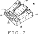
図1は、本発明に従う、フットコントローラー10を示す。フットコントローラー10は、本体部分12、加速器型ペダル14、およびコントロールボタン16を備える。使用において、フットコントローラー10は、代表的に眼科手術システム(例えば、Bausch & Lomb Inc.から入手可能なMillennium(登録商標)system(示さず))に装着されている。加速器型ペダル14またはスイッチ16の使用によるフットコントローラー10は、周知のように、種々の手術用器具を作動させ、制御する。ペダル14およびスイッチ16に加えて、本発明は、スイッチ24を覆うドア18を組み込む(下に示す)。ドア18は、図1の閉まった状態の場合、かかとの支えとして機能し、図2の開いた状態の場合、スイッチの蓋として機能する。好ましくは、ドア18は、使用者の快適のために、かかと支え隆起部20を備える。さらに、ドア18は、好ましくは外科医が、ドア18を容易に開くのを可能にするつま先隆起部22を備える。しかし、フットコントローラー10が、スイッチ24および/または16を覆う1つ以上のドア18を有し得ることが、示される。ドア18がまた、かかと支えである必要はない。
Detailed Description of Preferred Embodiments
FIG. 1 shows a
図2は、開いた状態でのドア18を有するフットコントローラー10を示す。見られ得るように、手術用器具(例えば、レーザー)を制御するスイッチ24は、ドア18によって効果的に囲われ、それによってスイッチ24の意図されない作動を防ぐ。好ましくはドア18は、スプリング装填され、その結果、開いた戻り止めされた状態である場合を除いて、自動的に閉まる。
FIG. 2 shows the
このように、蓋を必要とする手術用スイッチ24は、眼科手術における使用のための他の代表的なフットコントローラーに便利に取りこまれている。
Thus, the
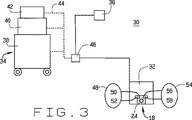
図3は、フットコントローラー32、手術用コンソール34、および必要に応じて、付随のフットスイッチ36から成り立つ眼科手術システム30を示す。手術用コンソール34は、カート38、基部またはコントロールユニット40、および必要に応じて、拡張ユニット42を含み得る。破線44によって示されるように、フットコントローラー32およびスイッチ36が、ユニット38,40,42のいずれか1つに連結され得る。必要に応じた付随フットスイッチ36は、共通の節点46を介して手術用コンソール34に連結されているのが示される。付随フットスイッチ36が、一般に1つの外科用装置(例えば、手術用レーザー)に供され、そして一般に、上で考察されたように囲われる必要があることが理解されるべきである。
FIG. 3 shows an ophthalmic
実際には、外科医が患者の周りを動きながら、スイッチ36が、主なフットコントローラー32よりも簡単に動くという点において、外科医の便利さのためにこのような付随スイッチ36を有することが望ましくあり得る。安全のために、スイッチ24が偶発的に作動しないことを確実にするために、フットコントローラー32にインターロックまたはセーフティーチェックを有することが、望ましい。
In practice, it is desirable to have such an associated switch 36 for the convenience of the surgeon in that the switch 36 moves more easily than the
スイッチ24が、フットコントローラー32上で、偶発的に作動しないことを確かめるために、ドア18が、開いた状態にある場合を除いて手術用スイッチ24の作動を不可能にするためのドア状態センサー48を有することが、望ましい。ドア状態センサー48は、ホール効果IC52と組み合わされるマグネット50を含み得、ホール効果センサーを形成し得る。次いで、マグネットが、ホール効果IC52に近接した位置に移動する場合、スイッチ24が、使用可能になる。余剰が所望される状況の場合、ドアがフットコントローラー上にあることを検出するためのドア存在センサー54がまた、使用され得る。センサー48のように、センサー54は、ドア18上のマグネット56およびホール効果IC58を含み得る。センサー48が、ドアが適切な位置にあることを検出するのとほとんど同じように、センサー54が使用される場合、次いでスイッチ24が使用可能になる前にドア18の存在が検出されなければならない。すなわち、このような余剰なシステム(redundant system)において、手術用スイッチ24は、センサー54およびセンサー48によってそれぞれ検出されるような、ドアが存在し開いている場合を除いて、使用不能である。スイッチ24が使用可能である前に開かれているべき必要なドア18が、ドア18とスイッチ24との間に積まれている外部の物体がドア18に近づいて手術用装置を作動させるのを防ぐ。
A door condition sensor for disabling operation of the
本発明のなおさらなる実施形態において、フットコントローラー32から分離され、しかし電気的に連結している付随スイッチ36は、センサー48およびセンサー54によって使用可能になり得る。このような配置において、付随体36は、ドア18が開いた状態にある場合を除いて使用不能である。または、余分なシステムにおいて、付随体36は、ドア18が存在し開いた状態にある場合を除いて使用不能である。スイッチ24またはスイッチ36の不注意の操作が手術室における患者または他の人を重大に傷つけさせ得るために、このような配置は、コンソール34が、スイッチ24および/またはスイッチ36によって制御されるレーザーを備える場合、非常に所望され得る。
In still further embodiments of the present invention, an associated switch 36 that is separate from, but electrically coupled to, the
本発明の手術システム30の種々の実施形態が、記載されてきた。フットコントローラー32、スイッチ24、および付随スイッチ36の使用不能が、センサー48およびセンサー54を使用するか使用しないに関わらず手術用コンソール34から生じ得る。
Various embodiments of the
フットコントローラー32が、センサー48およびセンサー54が加えられたことを除いて、フットコントローラー10とほとんど同一であることが、示される。
It is shown that the
図4は、市販されているホール効果IC52および58を取り込む回路のブロック図を示す。ホール効果IC52に加えて、センサー48は、スイッチ60(好ましい実施形態においてスイッチ60およびスイッチ64は、組み合わされてスイッチ24を形成する)を備え、このスイッチは、中継器62に接続される。スイッチ60が電力を供給され、使用可能になる場合、ホール効果IC52が、マグネット50の存在を検出することなしに、スイッチ60は、一般的に電気的に開放しており、電力が供給されない。使用可能な状態において、次いでスイッチ60は、中継器62を制御する。次いで中継器62は、使用可能シグナルを、手術用コンソール34に送り、手術用器具をスイッチ24と結合させて作動させる。余剰(redundancy)が所望される場合は、次いでホール効果IC58が、ホール効果IC52と協同して、スイッチ24および/またはスイッチ36を使用可能にし、または使用不能にする。
FIG. 4 shows a block diagram of a circuit that incorporates commercially available
スイッチ64および中継器66は、スイッチ60および中継器62についての余剰(redundancy)を提供する。スイッチ60が、電力が供給されかつ使用可能な状態ではなくなった状況において、スイッチ64および中継器66は、スイッチ24に装着された手術用器具は、偶発的に使用可能にはならないことを確実にする。同様な様式で、ホール効果IC58は、ホール効果IC52の機能停止による偶発的な作動を妨げる。従って、IC52、スイッチ64、および中継器62のみが、図4の回路の作動に必要である。IC58、スイッチ64、および中継器66は、安全の代理機能性(safety redundancy)を供給する。
Switch 64 and
Claims (5)
種々の手術器具の作動および制御のための加速器型ペダル;および
スイッチを覆うドアであって、ここで該ドアが、閉まった状態の場合、該加速器型ペダルの使用の間かかとの支えとして機能し、開いた状態の場合スイッチの蓋として機能する、ドア、
を備える、フットコントローラー。Foot controller for use in ophthalmic surgery, including:
An accelerator pedal for actuation and control of various surgical instruments; and a door that covers a switch, where the door functions as a heel support during use of the accelerator pedal when the door is closed. Acts as a switch lid when in the open state, door,
With a foot controller.
種々の手術用器具の作動および制御のための複数のスイッチ、を備え、
ここで複数のスイッチの少なくとも1つがドアによって覆われ、そしてその結果該ドアが、開かれた状態においてスイッチの蓋として機能する、フットコントローラー。Foot controller for use in ophthalmic surgery, including:
A plurality of switches for actuation and control of various surgical instruments,
A foot controller, wherein at least one of the plurality of switches is covered by a door, so that the door functions as a switch lid when opened.
Applications Claiming Priority (2)
| Application Number | Priority Date | Filing Date | Title |
|---|---|---|---|
| US10/025,424 US6689975B2 (en) | 2001-12-19 | 2001-12-19 | Foot controller including multiple switch arrangement with heel operated, door-type switch actuator |
| PCT/US2002/039195 WO2003053294A2 (en) | 2001-12-19 | 2002-12-06 | Foot controller |
Related Child Applications (1)
| Application Number | Title | Priority Date | Filing Date |
|---|---|---|---|
| JP2008224028A Division JP2009006162A (en) | 2001-12-19 | 2008-09-01 | Foot controller |
Publications (2)
| Publication Number | Publication Date |
|---|---|
| JP2005512677A JP2005512677A (en) | 2005-05-12 |
| JP4201713B2 true JP4201713B2 (en) | 2008-12-24 |
Family
ID=21825970
Family Applications (2)
| Application Number | Title | Priority Date | Filing Date |
|---|---|---|---|
| JP2003554055A Expired - Lifetime JP4201713B2 (en) | 2001-12-19 | 2002-12-06 | Foot controller |
| JP2008224028A Pending JP2009006162A (en) | 2001-12-19 | 2008-09-01 | Foot controller |
Family Applications After (1)
| Application Number | Title | Priority Date | Filing Date |
|---|---|---|---|
| JP2008224028A Pending JP2009006162A (en) | 2001-12-19 | 2008-09-01 | Foot controller |
Country Status (10)
| Country | Link |
|---|---|
| US (1) | US6689975B2 (en) |
| EP (1) | EP1463471B1 (en) |
| JP (2) | JP4201713B2 (en) |
| CN (1) | CN1273097C (en) |
| AT (1) | ATE404141T1 (en) |
| AU (1) | AU2002359644B2 (en) |
| CA (1) | CA2469903C (en) |
| DE (1) | DE60228327D1 (en) |
| ES (1) | ES2310217T3 (en) |
| WO (1) | WO2003053294A2 (en) |
Families Citing this family (27)
| Publication number | Priority date | Publication date | Assignee | Title |
|---|---|---|---|---|
| US7259340B2 (en) * | 2002-06-11 | 2007-08-21 | Sherwood Services Ag | Illuminated foot-switch |
| US6862951B2 (en) | 2002-08-26 | 2005-03-08 | Alcon, Inc. | Footswitch |
| US20040224053A1 (en) * | 2003-05-06 | 2004-11-11 | Markham Joseph P. | Habitat for caged animals and method of improving animal environment |
| AT500142B1 (en) * | 2003-07-31 | 2008-02-15 | W & H Dentalwerk Buermoos Gmbh | FOOT CONTROL |
| US7193169B2 (en) | 2003-10-29 | 2007-03-20 | Alcon, Inc. | Ergonomic footswitch |
| US7019234B1 (en) | 2003-11-13 | 2006-03-28 | Alcon, Inc. | Footswitch |
| US7084364B2 (en) | 2003-11-13 | 2006-08-01 | Alcon, Inc. | Dual control footswitch assembly |
| CA2539271C (en) * | 2005-03-31 | 2014-10-28 | Alcon, Inc. | Footswitch operable to control a surgical system |
| US7619171B2 (en) * | 2005-06-30 | 2009-11-17 | Alcon, Inc. | Multifunction surgical footswitch |
| US7626132B2 (en) | 2005-10-13 | 2009-12-01 | Alcon, Inc. | Foot controller |
| US7381917B2 (en) | 2006-09-20 | 2008-06-03 | Alcon, Inc. | Footswitch assembly with position memory |
| US8465473B2 (en) * | 2007-03-28 | 2013-06-18 | Novartis Ag | Surgical footswitch with movable shroud |
| US10363166B2 (en) | 2007-05-24 | 2019-07-30 | Johnson & Johnson Surgical Vision, Inc. | System and method for controlling a transverse phacoemulsification system using sensed data |
| US10485699B2 (en) | 2007-05-24 | 2019-11-26 | Johnson & Johnson Surgical Vision, Inc. | Systems and methods for transverse phacoemulsification |
| US10596032B2 (en) | 2007-05-24 | 2020-03-24 | Johnson & Johnson Surgical Vision, Inc. | System and method for controlling a transverse phacoemulsification system with a footpedal |
| AR072011A1 (en) * | 2008-06-05 | 2010-07-28 | Alcon Res Ltd | WIRELESS NETWORK AND WIRELESS COMMUNICATION METHODS FOR OPHTHALMIC SURGICAL CONSOLES |
| US8076599B2 (en) * | 2008-09-10 | 2011-12-13 | Mora Assad F | Foot actuated switch |
| US20160095507A1 (en) | 2010-05-13 | 2016-04-07 | Beaver-Visitec International, Inc. | Laser video endoscope |
| US10226167B2 (en) | 2010-05-13 | 2019-03-12 | Beaver-Visitec International, Inc. | Laser video endoscope |
| EP2484327A3 (en) * | 2011-02-08 | 2013-10-09 | Hill-Rom Services, Inc. | Occupant support with multi-modal contol |
| USD669441S1 (en) * | 2011-03-04 | 2012-10-23 | Carl Zeiss Meditec Ag | Foot pedal |
| CN103208378B (en) * | 2012-01-17 | 2015-07-22 | 第一传动科技股份有限公司 | Foot control switch with security mechanism |
| USD665756S1 (en) * | 2012-01-24 | 2012-08-21 | Timotion Technology Co. Ltd. | Foot pedal |
| NL2019147B1 (en) | 2017-06-29 | 2019-01-14 | D O R C Dutch Ophthalmic Res Center International B V | A foot pedal control unit |
| US10901450B2 (en) | 2018-08-21 | 2021-01-26 | Alcon Inc. | Multi-functional surgical foot controller with integrated shroud |
| US11740648B2 (en) * | 2019-08-01 | 2023-08-29 | Alcon Inc. | Surgical footswitch having elevated auxiliary buttons |
| US11845178B2 (en) | 2020-11-03 | 2023-12-19 | Techtronic Cordless Gp | Modular work station |
Family Cites Families (18)
| Publication number | Priority date | Publication date | Assignee | Title |
|---|---|---|---|---|
| US3785222A (en) * | 1972-11-15 | 1974-01-15 | Bohn Dawson Inc | Foot control guard |
| US3801800A (en) * | 1972-12-26 | 1974-04-02 | Valleylab Inc | Isolating switching circuit for an electrosurgical generator |
| DE7511072U (en) * | 1975-04-09 | 1975-10-23 | Bernstein H Spezialfabrik Fuer Schaltkontakte | Foot switch |
| DE2715608C3 (en) * | 1977-04-07 | 1983-04-28 | Gebr.Claas Maschinenfabrik GmbH, 4834 Harsewinkel | Switching device for automatic steering on agricultural machines |
| US4463759A (en) * | 1982-01-13 | 1984-08-07 | Garito Jon C | Universal finger/foot switch adaptor for tube-type electrosurgical instrument |
| US5091656A (en) * | 1989-10-27 | 1992-02-25 | Storz Instrument Company | Footswitch assembly with electrically engaged detents |
| US5166513A (en) * | 1991-05-06 | 1992-11-24 | Coherent, Inc. | Dual actuation photoelectric foot switch |
| US5340953A (en) * | 1992-11-19 | 1994-08-23 | A-Dec, Inc. | Switch controller |
| US5434457A (en) * | 1993-07-30 | 1995-07-18 | Josephs; Harold | Foot pedal safety switch and safety circuit |
| US5712460A (en) * | 1994-07-19 | 1998-01-27 | Linvatec Corporation | Multi-function surgical device control system |
| US5568859A (en) * | 1995-08-08 | 1996-10-29 | Laser Industries, Limited | Foldable foot switch |
| US5635777A (en) * | 1995-12-28 | 1997-06-03 | Andrew Telymonde | Foot operated control apparatus |
| WO1998008479A1 (en) * | 1996-08-29 | 1998-03-05 | Storz Instrument Company | Dual loop frequency and power control |
| US5983749A (en) * | 1997-09-12 | 1999-11-16 | Allergan Sales, Inc. | Dual position foot pedal for ophthalmic surgery apparatus |
| US6150623A (en) | 1998-08-27 | 2000-11-21 | Allergan | Back-flip medical footpedal |
| JP2000287993A (en) * | 1999-04-05 | 2000-10-17 | Olympus Optical Co Ltd | Foot switch for medical use |
| WO2002032354A1 (en) * | 2000-10-17 | 2002-04-25 | Alcon, Inc. | Mappable foot controller for microsurgical system |
| US7012203B2 (en) * | 2001-09-07 | 2006-03-14 | Carl Zeiss Surgical Gmbh | Foot switch pedal controller for a surgical instrument |
-
2001
- 2001-12-19 US US10/025,424 patent/US6689975B2/en not_active Expired - Lifetime
-
2002
- 2002-12-06 ES ES02794196T patent/ES2310217T3/en not_active Expired - Lifetime
- 2002-12-06 JP JP2003554055A patent/JP4201713B2/en not_active Expired - Lifetime
- 2002-12-06 WO PCT/US2002/039195 patent/WO2003053294A2/en active Application Filing
- 2002-12-06 EP EP02794196A patent/EP1463471B1/en not_active Expired - Lifetime
- 2002-12-06 CA CA002469903A patent/CA2469903C/en not_active Expired - Lifetime
- 2002-12-06 AT AT02794196T patent/ATE404141T1/en not_active IP Right Cessation
- 2002-12-06 AU AU2002359644A patent/AU2002359644B2/en not_active Expired
- 2002-12-06 CN CNB028252373A patent/CN1273097C/en not_active Expired - Lifetime
- 2002-12-06 DE DE60228327T patent/DE60228327D1/en not_active Expired - Lifetime
-
2008
- 2008-09-01 JP JP2008224028A patent/JP2009006162A/en active Pending
Also Published As
| Publication number | Publication date |
|---|---|
| ES2310217T3 (en) | 2009-01-01 |
| CN1604762A (en) | 2005-04-06 |
| CA2469903C (en) | 2008-11-18 |
| JP2005512677A (en) | 2005-05-12 |
| EP1463471A2 (en) | 2004-10-06 |
| US20030132092A1 (en) | 2003-07-17 |
| AU2002359644A1 (en) | 2003-07-09 |
| CA2469903A1 (en) | 2003-07-03 |
| AU2002359644B2 (en) | 2007-10-25 |
| DE60228327D1 (en) | 2008-09-25 |
| US6689975B2 (en) | 2004-02-10 |
| EP1463471B1 (en) | 2008-08-13 |
| WO2003053294A2 (en) | 2003-07-03 |
| CN1273097C (en) | 2006-09-06 |
| ATE404141T1 (en) | 2008-08-15 |
| JP2009006162A (en) | 2009-01-15 |
| WO2003053294A3 (en) | 2003-12-04 |
Similar Documents
| Publication | Publication Date | Title |
|---|---|---|
| JP4201713B2 (en) | Foot controller | |
| JP4224550B2 (en) | Foot controller with interlock circuit | |
| TWI375553B (en) | Improved foot controller | |
| CA2612139C (en) | Multifunction surgical footswitch | |
| JP2008012315A (en) | Multifunction surgical probe and ophthalmology/surgery system | |
| JP2561210Y2 (en) | Ophthalmic surgery device |
Legal Events
| Date | Code | Title | Description |
|---|---|---|---|
| A621 | Written request for application examination |
Free format text: JAPANESE INTERMEDIATE CODE: A621 Effective date: 20051115 |
|
| A131 | Notification of reasons for refusal |
Free format text: JAPANESE INTERMEDIATE CODE: A131 Effective date: 20080612 |
|
| A521 | Request for written amendment filed |
Free format text: JAPANESE INTERMEDIATE CODE: A523 Effective date: 20080901 |
|
| TRDD | Decision of grant or rejection written | ||
| A01 | Written decision to grant a patent or to grant a registration (utility model) |
Free format text: JAPANESE INTERMEDIATE CODE: A01 Effective date: 20080926 |
|
| A01 | Written decision to grant a patent or to grant a registration (utility model) |
Free format text: JAPANESE INTERMEDIATE CODE: A01 |
|
| A61 | First payment of annual fees (during grant procedure) |
Free format text: JAPANESE INTERMEDIATE CODE: A61 Effective date: 20081007 |
|
| R150 | Certificate of patent or registration of utility model |
Ref document number: 4201713 Country of ref document: JP Free format text: JAPANESE INTERMEDIATE CODE: R150 Free format text: JAPANESE INTERMEDIATE CODE: R150 |
|
| FPAY | Renewal fee payment (event date is renewal date of database) |
Free format text: PAYMENT UNTIL: 20111017 Year of fee payment: 3 |
|
| FPAY | Renewal fee payment (event date is renewal date of database) |
Free format text: PAYMENT UNTIL: 20111017 Year of fee payment: 3 |
|
| FPAY | Renewal fee payment (event date is renewal date of database) |
Free format text: PAYMENT UNTIL: 20121017 Year of fee payment: 4 |
|
| R250 | Receipt of annual fees |
Free format text: JAPANESE INTERMEDIATE CODE: R250 |
|
| FPAY | Renewal fee payment (event date is renewal date of database) |
Free format text: PAYMENT UNTIL: 20121017 Year of fee payment: 4 |
|
| FPAY | Renewal fee payment (event date is renewal date of database) |
Free format text: PAYMENT UNTIL: 20131017 Year of fee payment: 5 |
|
| R250 | Receipt of annual fees |
Free format text: JAPANESE INTERMEDIATE CODE: R250 |
|
| R250 | Receipt of annual fees |
Free format text: JAPANESE INTERMEDIATE CODE: R250 |
|
| R250 | Receipt of annual fees |
Free format text: JAPANESE INTERMEDIATE CODE: R250 |
|
| R250 | Receipt of annual fees |
Free format text: JAPANESE INTERMEDIATE CODE: R250 |
|
| R250 | Receipt of annual fees |
Free format text: JAPANESE INTERMEDIATE CODE: R250 |
|
| R250 | Receipt of annual fees |
Free format text: JAPANESE INTERMEDIATE CODE: R250 |
|
| R250 | Receipt of annual fees |
Free format text: JAPANESE INTERMEDIATE CODE: R250 |
|
| R250 | Receipt of annual fees |
Free format text: JAPANESE INTERMEDIATE CODE: R250 |
|
| R250 | Receipt of annual fees |
Free format text: JAPANESE INTERMEDIATE CODE: R250 |
|
| R250 | Receipt of annual fees |
Free format text: JAPANESE INTERMEDIATE CODE: R250 |
|
| R250 | Receipt of annual fees |
Free format text: JAPANESE INTERMEDIATE CODE: R250 |
|
| EXPY | Cancellation because of completion of term |