JP4201354B2 - Disposable delivery device for endoluminal prosthesis - Google Patents
Disposable delivery device for endoluminal prosthesis Download PDFInfo
- Publication number
- JP4201354B2 JP4201354B2 JP50978699A JP50978699A JP4201354B2 JP 4201354 B2 JP4201354 B2 JP 4201354B2 JP 50978699 A JP50978699 A JP 50978699A JP 50978699 A JP50978699 A JP 50978699A JP 4201354 B2 JP4201354 B2 JP 4201354B2
- Authority
- JP
- Japan
- Prior art keywords
- sheath
- prosthesis
- delivery system
- handle
- endoluminal prosthesis
- Prior art date
- Legal status (The legal status is an assumption and is not a legal conclusion. Google has not performed a legal analysis and makes no representation as to the accuracy of the status listed.)
- Expired - Lifetime
Links
- JAPMJSVZDUYFKL-UHFFFAOYSA-N C1C2C1CCC2 Chemical compound C1C2C1CCC2 JAPMJSVZDUYFKL-UHFFFAOYSA-N 0.000 description 1
Images


Classifications
-
- A—HUMAN NECESSITIES
- A61—MEDICAL OR VETERINARY SCIENCE; HYGIENE
- A61F—FILTERS IMPLANTABLE INTO BLOOD VESSELS; PROSTHESES; DEVICES PROVIDING PATENCY TO, OR PREVENTING COLLAPSING OF, TUBULAR STRUCTURES OF THE BODY, e.g. STENTS; ORTHOPAEDIC, NURSING OR CONTRACEPTIVE DEVICES; FOMENTATION; TREATMENT OR PROTECTION OF EYES OR EARS; BANDAGES, DRESSINGS OR ABSORBENT PADS; FIRST-AID KITS
- A61F2/00—Filters implantable into blood vessels; Prostheses, i.e. artificial substitutes or replacements for parts of the body; Appliances for connecting them with the body; Devices providing patency to, or preventing collapsing of, tubular structures of the body, e.g. stents
- A61F2/95—Instruments specially adapted for placement or removal of stents or stent-grafts
- A61F2/962—Instruments specially adapted for placement or removal of stents or stent-grafts having an outer sleeve
- A61F2/966—Instruments specially adapted for placement or removal of stents or stent-grafts having an outer sleeve with relative longitudinal movement between outer sleeve and prosthesis, e.g. using a push rod
-
- A—HUMAN NECESSITIES
- A61—MEDICAL OR VETERINARY SCIENCE; HYGIENE
- A61F—FILTERS IMPLANTABLE INTO BLOOD VESSELS; PROSTHESES; DEVICES PROVIDING PATENCY TO, OR PREVENTING COLLAPSING OF, TUBULAR STRUCTURES OF THE BODY, e.g. STENTS; ORTHOPAEDIC, NURSING OR CONTRACEPTIVE DEVICES; FOMENTATION; TREATMENT OR PROTECTION OF EYES OR EARS; BANDAGES, DRESSINGS OR ABSORBENT PADS; FIRST-AID KITS
- A61F2/00—Filters implantable into blood vessels; Prostheses, i.e. artificial substitutes or replacements for parts of the body; Appliances for connecting them with the body; Devices providing patency to, or preventing collapsing of, tubular structures of the body, e.g. stents
- A61F2/95—Instruments specially adapted for placement or removal of stents or stent-grafts
- A61F2/9517—Instruments specially adapted for placement or removal of stents or stent-grafts handle assemblies therefor
Landscapes
- Health & Medical Sciences (AREA)
- Engineering & Computer Science (AREA)
- Biomedical Technology (AREA)
- Cardiology (AREA)
- Oral & Maxillofacial Surgery (AREA)
- Transplantation (AREA)
- Heart & Thoracic Surgery (AREA)
- Vascular Medicine (AREA)
- Life Sciences & Earth Sciences (AREA)
- Animal Behavior & Ethology (AREA)
- General Health & Medical Sciences (AREA)
- Public Health (AREA)
- Veterinary Medicine (AREA)
- Prostheses (AREA)
- Media Introduction/Drainage Providing Device (AREA)
Description
発明の背景
1.発明の技術分野
本発明は、一般的には、ステント(stent)、ステント−移植片(stent-graft)等のような管状の内腔内人工補綴物に関する。より詳細には、本発明は、身体の内腔内、特に動脈瘤、狭窄症等の治療のために脈管系内に人工補綴物を正確かつ安全に配置すべくこれらに用いられる改良された送出システムおよび方法に関する。
動脈瘤は、通常は病気および/または遺伝的素質に起因する血管の異常な拡張の結果であり、動脈壁を脆くしまたこれを拡張する。脈瘤はどの血管でも起こり得る。最も起こり得るのは、大動脈および周辺の動脈であり、大多数は腹部大動脈に生じる大動脈の脈瘤であるが、通常、腎臓動脈の下方に始まり、多くの場合、腸骨動脈の一つまたは両方へと伸びている。
大動脈の脈瘤については、現在では開腹手術の処置がとられ、罹患した血管部分を迂回して該血管部分を人工導管移植片で修復する。効果的な外科的手法が考えられる一方で、致命的な破裂した腹部大動脈の脈瘤の代案を特に考慮すると、従来の導管移植片手術では多くの不利がある。外科手術は複雑であり、また、経験豊富な外科医と設備の整った外科施設とを必要とする。しかし、最高の外科医と設備とをもってしても、治療を受ける患者は、多くの場合、高齢でありまた心臓血管その他の病気で弱っており、これが適格な患者の数を減らしている。破裂前の適格な患者でさえ、これまでの動脈瘤修復における死亡率は、通常、2%から10%と比較的高い。これまでの外科手術に関連する病状は、心筋梗塞、腎不全、インポテンス、麻痺その他の状態を含む。加えて、手術が成功しても、回復に数週間を要し、また、多くの場合、長期の病院滞在を必要とする。
これらの不利益の一部または全部を解消するため、動脈瘤の治療のための内腔内人工補綴物の配置が提案されている。非常に有望ではあるが、これらの提案方法および装置の多くは、望ましくない制限を受ける。特に、脈管系内の血管内人工補綴物の正確な送出および配置が問題となる。
ステント−移植片は、多くの場合、周囲の血管壁に対して拡張または膨張するように偏倚される弾力のある構造を有する。このような弾性的に膨張するステント−移植片は、カテーテル内で強く圧迫され、カテーテルの鞘の周囲に対して大きい力を及ぼす。これは、多くの場合、特に弾性的に膨張する構造が前記カテーテル材料内に入るとき、前記ステント−移植片と前記鞘との間に過剰な摩擦をもたらす。これらのカテーテルは、多くの場合、曲がった脈管系のシステム内で巧みに操作することが求められるため、前記カテーテル壁の弾性材料内で強く圧迫されたステント−移植片の鞘入れが特にやり易い弾力のある長尺体として形成される。
これらの理由から、動脈瘤および身体の内腔のその他の病気の治療のため、ステント、ステント−移植片等のような人工補綴物の内腔内配置のための改良された装置、システムおよび方法を提供することが望まれる。このような改良されたシステムおよび方法が、配置時間、機器費または配置手順の複雑さを極端に増大させることなしに、配置手順の正確性および安全性を高めるものであることが特に望ましい。
2.背景技術の説明
人工補綴物の内腔内配置のための装置は、米国特許第4,512,338号、第4,651,738号、第4,665,918号、第5,458,615号、第5,480,423号、第5,484,418号、第5,489,295号、第4,990,151号、第5,035,706号、第5,433,723号、第5.443,477号、第5,282,824号、第5,275,622号、第5,242,399号、第5,201,757号、第5,190,058号、第5,104,399号、第5,092,877号および第4,990,151号、並びに欧州特許公報EP 0 539 237 A1、0 518 839 A2、EP 0 505 686 A1およびEP 0 508 473 A2に記載されている。
発明の概要
本発明は、身体の内腔内への内腔内人工補綴物の配置、特に脈管系内へのステントおよびステント−移植片の配置のための改良されたシステム、装置および方法を提供する。公知の送出システムを超える第1の改良では、鞘の位置に従って変化する、可変の機械的倍率を有する操作機構を用いて、強く圧迫された人工補綴物の全面から前記鞘が取り除かれる。これは、前記鞘の移動を容易かつ正確に開始することを可能にする。一旦、配置が安全に進行し、静的摩擦力に打ち勝った後は、前記配置の残りは、全体的に安全性または使用の容易性を極端に低下させることなしに、より迅速に進行する。他の改良点においては、前記操作機構のためのハンドルが前記鞘の軸線と平行な軸線の周りに回転可能であり、これによ、前記人工補綴物または送出システムに前記ハンドルにより伝えられる不注意による基端部および末端部のいかなる移動をも回避する。また、この送出システムの使用上の正確性および容易性は、前記鞘内の人工補綴物拘束部材に連結される前記鞘の周りに外管を付与することにより改良される。この外管は導入弁を通して挿入され、その結果、前記鞘が基端部側に引っ込められるとき、前記外管と前記導入弁との間の摩擦が前記人工補綴物を目標位置に拘束するのに役立つ。
本発明は、第1に、管状の内腔内人工補綴物に使用する送出システムを提供する。この送出システムは、基端部と、末端部と、内腔とを有する鞘を含む。前記内腔は、前記末端部の近傍で、前記人工補綴物を受け入れることができる。前記鞘の内腔内の部材は、前記鞘が前記部材に関する前記内腔内人工補綴物の末端位置から前記内腔内人工補綴物の基端位置へ移動するとき、前記人工補綴物を追い出すように適合されている。操作機構が前記部材に取り付けられており、また、前記操作機構は前記鞘が前記内腔内人工補綴物の末端位置から前記内腔内人工補綴物の基端位置との間で移動するときに機械的倍率が変化するようにハンドルを前記鞘に連結している。
一般に、前記ハンドルの変位は、前記鞘が前記内腔内人工補綴物の末端位置の近傍にあるときは、前記部材に関する前記鞘の第1の変位を生じさせる。このハンドルの同じ変位は、前記鞘が前記内腔内人工補綴物の基端位置の近傍にあるときには、前記部材に関する前記鞘の非常に大きい変位をもたらす。典型的には、最初の機械的倍率は、前記人工補綴物と前記鞘との間の静的摩擦力に打ち勝つために大きく、前記鞘をゆっくりとかつ正確に引っ込めることができる。一旦、前記鞘が前記人工補綴物の全面を滑動し始めると、また、ある実施例においては、一旦、前記人工補綴物の端部が周囲の内腔壁と係合するように膨張すると、低い機械的倍率を用いることにより前記配置がより迅速な進度で進む。
また、その他に、本発明は半径方向に膨張可能である管状の内腔内人工補綴物に使用される人工補綴物送出システムを提供する。この送出システムは、基端部と、末端部と、これらの端部間の軸線と、前記末端部の近傍で前記人工補綴物を受け入れ可能である内腔とを有する鞘を含む。部材が、前記鞘が前記部材に関する前記内腔内人工補綴物の末端位置から前記内腔内人工補綴物の基端位置へ移動するときに前記内腔から前記人工補綴物を追い出すため、前記内腔に配置されている。操作機構が前記部材に取り付けられており、また、前記鞘をハンドルに連結している。前記ハンドルは前記鞘の軸線に実質的に平行な軸線の周りに回転可能であり、前記内腔内人工補綴物の末端位置から前記内腔内人工補綴物の基端位置への前記鞘の移動に影響を及ぼす。
さらに、その他に、本発明は、患者の身体内に管状の内腔内人工補綴物を挿入するための送出システムを提供する。この送出システムは、基端部と、末端部と、該末端部の近傍で前記人工補綴物を受け入れ可能である内腔とを有する鞘を含む。部材が前記内腔内に配置されており、前記鞘が前記部材に関する前記内腔内人工補綴物の末端位置から前記内腔内人工補綴物の基端位置へ移動するときに前記内腔から前記人工補綴物を追い出すように適合されている。外管が前記鞘を覆って配置されている。ハウジングが前記鞘の基端部の近傍で前記部材に取り付けられ、また、前記鞘が前記内腔内人工補綴物の末端位置から前記内腔内人工補綴物の基端位置へ移動するときに前記外管が前記部材と実質的に同軸に整列して残るように前記外管に連結されている。前記外管は、多くの場合、導入弁内に挿入可能であり、その結果、前記外管と前記導入弁との間の摩擦が配置の間に前記目標位置に前記人工補綴物を保持するのに役立つ。
本発明の方法においては、半径方向へ膨張可能である管状の内腔内人工補綴物が鞘の内腔内で身体の内腔の目標位置に配置される。前記人工補綴物は、ハンドルを操作することにより前記鞘から離される。これは、前記内腔内人工補綴物の末端位置から前記内腔内人工補綴物の基端位置へ基端部側に前記鞘を引っ込める。前記ハンドルの変位は、前記鞘が前記内腔内人工補綴物の末端位置の近傍にあるときには前記鞘の第1の変位をもたらす。同じハンドルの変位は、前記鞘が前記内腔内人工補綴物の基端位置の近傍にあるとき、前記第1の鞘の変位と異なる前記鞘の第2の変位をもたらす。
本発明により提供される他の方法では、半径方向に膨張可能である内腔内人工補綴物が、該人工補綴物が鞘の内腔内に配置されている間に身体の内腔内の目標位置に前記人工補綴物を配置することにより配置される。前記人工補綴物は、ハンドルを回転させることにより、前記鞘から離される。前記ハンドルは、前記鞘の軸線と平行である軸線の周りに回転し、前記人工補綴物の全部にわたって前記鞘を軸線方向へ移動させる。
本発明のさらに他の方法では、半径方向に膨張可能である管状の内腔内人工補綴物が、導入弁を通して身体の内腔内に前記人工補綴物を挿入することにより配置される。前記人工補綴物は、鞘の内腔内に配置されている間に挿入される。外管もまた導入弁を通して挿入され、また、前記人工補綴物が身体の内腔内の広範囲に配置される。前記人工補綴物は、前記鞘を引き込みかつ前記鞘内に配置された部材で前記人工補綴物を拘束することにより前記鞘から離される。この部材は、前記人工補綴物を離す間に前記外管に関して軸線方向に拘束され、その結果、前記導入弁と前記外管との間の摩擦が前記目標位置からの前記人工補綴物の移動を阻止するのに役立つ。
【図面の簡単な説明】
図1は、代表的な筒状の血管のステント−移植片の単純化した側面図である。
図2は、本発明の原理に従う送出システムの斜視図である。
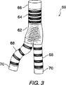
図3は、代表的なモジュール式の内腔内分岐人工補綴物を示す。
図4は、分岐人工補綴物を配置するために図2の送出システムを用いる方法を示す。
図5は、導入弁と送出鞘との間に低摩擦の密封を与えるために図2の送出システムで使用される外管を示す。
図6は、配置の間の人工補綴物の移動を阻止するために送出鞘と導入弁との間に外管を使用する方法を示す。
図7は、導入弁と人工補綴物との間の相対移動を外部支持ロッドで阻止する他の送出システムを示す。
図8は、図2の配置システムの操作機構を示す断面図である。
図9は、図8の操作機構の構成要素を示す分解図である。
図10および図11は、それぞれ、ピッチが可変であるねじを含む操作機構を有する他の配置システムの断面図および側面図である。
図12は、図10の配置システムで使用される可変ピッチねじを形成するためのマンドレルを示す。
図13は、図10の配置システムの操作ハンドルを貫く断面図である。
図14ないし図17は、図2および図10の配置システムで使用される操作システムの構成要素を示す。
好ましい実施例の説明
本発明は、半径方向へ膨張可能である管状の人工補綴物、特にステント(stent)、ステント−移植片およびこれらと同様のものを送出するための送出装置、システムおよび方法を提供する。本発明の送出機構および方法は、尿管、尿道、気管、鰓、食道、肝管およびこれらと同様のものについてステントを行う(stent)ことを含む、様々な治療上の使用に好適である。また、これらの構造および方法は、瘻孔の形成のためのような、一時的または長期の内腔を作るために有用である。本発明は、脈管系の病気の治療、特に動脈瘤、狭窄症およびこれらと同様のものの治療として、内腔内人工補綴物の送出のための迅速な適用を提供する。
以下に説明する構造および方法は、配置に先立ちまたは本来の位置において、軸線方向に一様な円筒状の人工補綴物、予め組み立てられた二股の人工補綴物、および、選択的な組立用補綴モジュールの配置において有用性を有する。モジュールの補綴構造および送出方法は、同時係属の米国特許出願である、1996年8月29日出願の第08/704,960号(代理人ドケット番号16380-003410)、1995年10月3日出願の第08/538,706号(代理人ドケット番号16380-003800)および1996年10月7日出願の60/028,928(代理人ドケット番号16380-004110)により詳細に記載されており、その完全な開示は参照によりここに組み入れられている。
図1を参照すると、代表的な円筒状の人工補綴物10は、複数の独立したリングフレーム14として形成された好ましい管状フレーム12を含む。管状フレーム12はインナーライナー18を支持する。選択的に、インナーライナー18の内側またはこれと組み合わせて、アウターライナーが前記リングフレームを覆って配置される。
ライナー18にリングフレーム14を固定するため、典型的には前記ライナーが前記フレームに縫合される。接着結合、熱溶接、超音波溶接およびこれらと同様のものを含む、代わりの様々なライナー/フレーム取り付け構造が利用可能である。好ましくは、ライナー18と周囲の本体の内腔との間の密閉性を高めるため、ライナー18はフレーム12の先端の基端部および末端部の間で縫合されている。
人工補綴物10は、典型的には、約20mmから500mmまでの範囲の長さを有し、好ましくは、50mmないし200mmである。人工補綴物10の緩んだ状態における直径は、ほぼ4mmから45mmまでの範囲内にあり、好ましくは、約5mmないし38mmの範囲内にある。
図2を参照すると、代表的な送出システム30は、管状の鞘32と、シャフト34とを含む。鞘32は、基端部38から末端部40まで伸びる内腔36を有する。シャフト34は内腔36内に滑動可能に受け入れられており、また、複数のランナー42が前記シャフトから末端部へ伸びている。これらのランナー42は内腔36の内面の一部を覆い、前記シャフトの内腔内を滑動する。また、シャフト34は内腔を有し、該内腔にコアシャフト44が固定されている。コアシャフト44はガイドワイヤ用内腔46を有する。ノーズコーン48がコアシャフト44の末端部に固定されており、このため、前記ノーズコーンは前記ランナーと共に操作することができる。代わりに、ノーズコーン48の独立した操作を可能とすべく、コアシャフト44をシャフト34内に滑動可能に配置することができる。
人工補綴物10は半径方向に圧迫されかつ複数のランナー42内に保持される。同様に、鞘32はこれらのランナー42が外側へ膨張または拡大しないようにする。これらのランナー42は好ましくは硬質材料で形成され、内腔36の内面に人工補綴物10の前記フレームからの膨張荷重を分配する。複数のランナー42を用いる人工補綴物の配置のための代表的な方法および装置は、1995年6月7日に出願された同時係属の米国特許出願番号08/475,200(代理人ドケット番号16380-001130)に、より完全に記載されており、その完全な開示は参照によりここに組み入れられている。
ハウジング50が鞘32の基端部38に配置されている。ハウジング50は、人工補綴物10がランナー42とシャフト34とによって軸線方向に拘束されている間に鞘32を基端部側に引っ込めるための操作機構を収容している。鞘32を基端部側へ引き込むため、図示のように、ハンドル52が前記鞘の軸線の周りに回転される。これは、配置の間に前記ハンドルの回転から前記送出システムのいかなる軸線方向移動をも不注意によって加えることを回避し、これにより、人工補綴物10が目標位置から軸線方向へ移ることを防止し、また、不注意によるランナー42の進行による周囲の身体の内腔を傷付けることを回避する。
鞘32を覆う外管54がハウジング50から末端部へ伸びている。シャフト34はハウジング50を貫通して伸び、コネクタ56に固定されており、該コネクタはハウジング50の基端部に取り外し可能に取り付けられている。したがって、シャフト34と外管54とは前記ハウジングを介して互いに連結され、その結果、ハンドル52が回転するとき、鞘32がこれらの2つの構造間で基端部側へ引っ込む。一旦、前記人工補綴物が配置されかつランナー42が前記人工補綴物と周囲の身体の内腔との間から基端部側へ滑動すると、ランナー42とノーズコーン48の基部とを後退させて鞘32の末端部内に戻すべく、コネクタ56がハウジング50から取り外される。
コアシャフト44のガイドワイヤ用内腔46へのガイドワイヤの導入を容易にし、あるいは不使用時に前記ガイドワイヤ用内腔が密封され得るように、ルア取り付け部品(luer fitting)がコネクタ56の基端部に固定されている。
図3を参照すると、組み立てられた二股の内腔内人工補綴物60は、幹部分64と2つの枝部分68との間の比較的堅い内腔分離部62を含む。内腔分離部62は、比較的高いコラムおよびフープ強さを与えるために連続したフレームを含み、これに対し、前記枝の端の幹部分が軸線方向に関する可撓性を高めるために複数のループが分離されている独立した複数のリングフレームまたは螺旋状のフレームで形成される。シーリングカフ66および70が健全な組織に前記人工補綴物を確実に固定し、また、血管の周囲のエンドリチウム(endolithium)に対して前記補綴内腔を密封する。
図4に概略的に示すように、二股の人工補綴物60の二股補綴モジュールが送出システムを使用して配置され、腹部大動脈瘤AAAを分離している。この最初の補綴モジュールは腹部大動脈AAAから第1の腸骨Iに伸び、また、膨張した動脈瘤を血液流動から効果的に密封するための円筒状の補綴モジュールを受け入れるための開口72を有する。前記補綴モジュールは、該モジュールを複数のランナー42内に軸線方向に関して拘束しかつ鞘32を基端部側へ引っ込めることにより配置される。典型的にはステンレス鋼のような高強度金属の薄いストリップを含むこれらのランナーは、鞘32の内腔に沿って滑動し、前記人工補綴物の弾力が少なくなるように外方へ曲がっている。一旦、前記補綴モジュールが完全に膨張されると、前記膨張された人工補綴物が前記ランナー間で血管壁と係合する間に前記ランナーは前記人工補綴物と周囲の血管壁との間から基端部側へ引っ込められる。
図4に示す前記二股の補綴モジュールは、該補綴モジュールの位置決めおよび組立を蛍光観察により容易にするための目立たない放射線不透過性の目印74を含む。この放射線不透過性の目印は、1996年4月5日に出願された同時係属の米国特許出願番号08/628,797(代理人ドケット番号16380-005600)および1997年6月17日に出願された同時係属の米国特許出願(代理人ドケット番号16380-005710)とにより完全に記載されており、その完全な開示は参照によりここに組み込まれている。
図5を参照すると、外管54は、一般に、管状体76とエンドキャップ78とを含む。O−リング80がエンドキャップ78内に配置され、鞘32の外面の周りに低摩擦の止血密封性を与える。前記したように、本発明のランナーは、前記半径方向に圧迫された人工補綴物に関し、鞘32を円滑に引っ込めることを容易にする。しかし、実質的な量の摩擦は、前記送出システムが患者の身体84に入る送出システム30の外面と導入鞘82との間で生じる。
導入鞘は、一般に、カテーテル、ガイドワイヤ、様々なサイズおよび外形の他の侵入外科用器具の周囲の止血を提供する。このような導入鞘は、典型的に、前記送出システムの最外層と半径方向に係合する弾性の密封体を有する。
一般に、鞘32を基端部側へ引き込む間に前記内部の人工補綴物を決まった位置に残すことが望ましいが、導入弁82と鞘32との間の摩擦は一般に不利に働く。しかし、図6に示すように、外管54をハウジング50に連結することにより、また、シャフト34とハウジング50とに関して鞘32を引っ込める操作機構を提供することにより、外管54と導入弁82との間の摩擦は、配置の間に前記目標位置に前記人工補綴物を拘束することに役立つように用いられる。
導入弁82への外管54の挿入を容易にするため、管状体76の末端部が先細にされている。ある実施例では、外管54と前記人工補綴物とが配置されると導入弁82が操作され、前記人工補綴物を決まった場所に固定するために前記外管に前記密封体を押し付ける。特に有利な操作可能の導入弁は、1996年11月6日に出願された同時係属米国特許出願番号08/744,659(代理人ドケット番号16380-006300)に記載されており、その完全な開示は参照によりここに組み込まれている。
患者の身体84内の人工補綴物の位置を維持するための代わりのシステムおよび方法が図7に記載されている。この実施例では、シャフト34に関する鞘32の引き込みのための操作機構が取り外し可能の操作ハウジング86内に収容されている。ハウジング86は、ブレースロッド88を用いて導入弁82に連結されている。ここに記載のハウジング86と前記操作機構とは、複数回の配置手順に再利用可能であるが、このシステムのコストは、特に前記ハウジングおよび操作機構の繰り返しの消毒を考慮すると、一般に図2に示す送出機構より高い。加えて、鞘32の軸線に対して直角に回転する操作ハンドルの使用は、配置の間の前記人工補綴物の不注意による軸線方向移動をもたらす。これは、ランナー42が身体の内腔の周囲に露出されるとき、前記ランナーのどのような末梢的な利点も前記内腔壁を傷付けまたはこれを貫通することになるため、特に問題がある。
ハンドル52の軸回転を鞘54の軸の並進運動に変換する操作機構90は、図8および図9を参照することにより理解されよう。ハンドル52は、内ねじ92を有する管状構造を含む。ハウジング50は、末端のハウジング部94と基端のハウジング部96とを含む。これらのハウジング部は、ねじ溝が設けられた前記ハンドル内を軸線方向へ伸びる、スロットが設けられた管98により共に保持されている。
スライダ100が鞘32の基端部に固定されている。スライダ100は、スロットが設けられた管98を取り囲む、ねじ山が設けられたリング102と、前記スロットが設けられた管の内部で支えられて動く内側の物体104とを含む。ねじ山が設けられたリング102は複数の止めねじ、前記内側の物体から半径方向に突出する複数のタブ、前記ねじ山が設けられたリングから半径方向内方へ突出する複数のタブ、またはこれらと同様のものにより内側の物体104に固定されている。それとは関係なく、スライダ100のある構造は、スロットが設けられた管98の複数のスロットを経て半径方向へ伸びており、これにより、前記スロットが設けられた管はスライダ100を回転するように拘束する。
補強ロッド106がハウジング50の基端部96から末端へ伸びている。補強管106は、スライダ100を貫通してハウジング50の末端部の近傍に伸び、また、鞘32の内腔に滑動するように受け入れられている。コネクタ56は、基端部の取付部108に連結可能である。コネクタ56はシャフト34に固定され、その結果、コネクタ56が基端部の取付部108に取り付けられるとき、ハウジング50が外管54とシャフト34との間に軸線方向に関する整列を維持する。補強管106は、スライダ100が基端側に移動するときのシャフト34の曲がりを防止する。
鞘32は、ハウジング50に関してハンドル52を回転させることにより基端側に引っ込められる。スライダ100のねじ山が設けられたリング102がハンドル52の内ねじと噛み合い、また、スロットが設けられた管98がスライダ100のハウジング50内での回転を制限しているため、前記ハンドルの回転が前記スライダと取り付けられた移植片カバーとを図示のように軸線方向へ引く。この実施例では、内ねじ92はハンドル52の長さに沿って一定であり、このため、前記ハウジングに関する前記ハンドルの特定の変位が、前記スライダの位置に拘わらず前記スライダの調和した軸線方向変位をもたらす。このような一定の内ねじは、ハンドル52と鞘32との間に約4:1から3:1の範囲の総機械的倍率を与える、約0.125および0.250の間のピッチを有する。後述するように、前記ねじは、多くの場合、2またはそれ以上のリードを有し、このため、隣接するねじ山の距離は1/2(またはそれ以下)のねじピッチである。
変位可変の送出システム110が図10および図11に示されている。ピッチ可変の送出システム110は、多くの前記したと同様の要素を含むが、可変ピッチの内ねじ114を有するハンドル112を利用する。可変ねじ114は、前記ハンドルの各回転が配置の最初の位相の間に管鞘32を基端部側へ比較的小さい軸線方向距離だけ移動させるように、ハンドル112の末端部の近傍に比較的小さいピッチを有する。これは、前記ハンドルと前記鞘との間に増大された機械的倍率を与え、外科医が前記人工補綴物と周囲の鞘との間の大きい静的摩擦力を克服するのに役立つ。また、この増大した機械的倍率は、周囲の鞘材料内への前記人工補綴物のフレームのどのような重積をも可能とするのに役立つ。その結果、前記人工補綴物の末端部(これは最初に配置される)は非常にゆっくりと解放され、前記人工補綴物が最初に周囲の身体の内腔に係合するときに外科医が前記配置位置の正確さを確かめることができる。これらの末端部側のねじは約0.125および0.375間のピッチを有し、約4:1から約2.5:1の範囲の機械的倍率を与える。
比較的小さいピッチを有する不変ねじの送出システムを用いることが可能であるが、これには、前記ハンドルを繰り返し回転させるのに相当の時間が必要である。加えて、一旦、前記静的摩擦力に打ち勝って前記鞘が動き始め、また、動摩擦力が典型的に静的摩擦力より低いとき、前記人工補綴物と周囲の鞘との間の摩擦力は低下する。さらに、ますます多くの前記人工補綴物が前記周囲の鞘から解放されるとき、前記人工補綴物と前記鞘との間の全法線力が低下する。これは、配置に関する摩擦をさらに減少させるように働く。前記人工補綴物の膨張された部分は、さらに、前記人工補綴物が前記周囲のランナー内で膨張するときの残りの圧迫された部分を軸線方向へ引っ張るのに役立つ。最後に、一旦、前記人工補綴物の端部が周囲の身体の内腔と堅く係合すると、前記人工補綴物と前記周囲の身体の内腔との間の関係が大部分定められ、その結果、配置がより迅速に安全に進められ得る。全てのこれらの相互作用の結果、前記人工補綴物が完全に配置される、前記鞘が末端位置118から前記人工補綴物の全部について基端位置120まで移動するとき、一般にはハンドル112と鞘32との間の前記機械的倍率を減少させることが望ましい。
可変ねじ114の使用、および、ハンドル112とスライダー100とスロットが設けられた管98との間の関係は、図12ないし図17を参照することにより理解されよう。図12は、可変ねじ114を押し付けるようにハンドル114が成形されたマンドレル122を示す。前記ハンドルは、多くの場合、マンドレル122上に2つの半部で成形され、該2つの半部は軸線方向に関して結合される。マンドレル122は、該マンドレルの軸線方向長さに沿ってピッチが変化する雄ねじ124を含む。好ましくは、ねじ124は、2またはそれ以上の螺旋状のねじ要素を有する多リードを有する。その結果、隣接するねじ要素間の距離126は、マンドレル122の末端部のピッチ128のわずかに1/2である。多リードねじの使用は、多数の要素が前記スライダーから軸線方向へ伸長し、前記周囲のねじと係合することを可能とし、これにより前記スライダーの安定性を高める。
前記したように、末端のピッチ128は基端のピッチ130より非常に小さく、その結果、前記ハンドルの定速回転は、前記人工補綴物に関する前記鞘の軸線方向速度の増大を生じさせる。ハンドル112の各回転は、好ましくは、鞘32が被覆位置118の近傍にあるとき、鞘32を約0.25インチの軸線方向距離だけ動かし、他方、前記ハンドルのこの同じ回転は、好ましくは、前記鞘が配置位置120の近傍にあるとき、前記鞘を約0.75インチの軸線方向距離だけ動かす。換言すると、代表的な実施例における末端のピッチ128は約0.25インチであり、他方、基端のピッチ130は約0.75インチである。前記ねじは、(図12に示すように)前記基端部および末端部間で直線的に変化し、あるいは、図10に示すように、実質的に階段状に変化するものとすることができる。さらに、これに代わるものとして、前記ねじの軸線方向長さに沿ったピッチの二次の変化が可能である。
図13ないし図15に示すように、スライダー100はフィンのついた内側の物体132を外側のリング134に結合することにより形成することができる。外側のリング134は、ハンドル112の可変の雌ねじ114の2つの螺旋状要素中に伸びる相対するピン136を含む。外側のリング134上の雄ねじではなく前記ピンの使用が、前記ねじのピッチが変化するときにスライダー100と前記ハンドルとの間の結合を阻止する。また、図13にスロットが設けられた管98とスライダー100との相互作用を示すように、これにより、ハンドル112が回転するときに前記スロットが設けられた管が前記スライダの回転を制限する。他の実施例においては、スライダー100は内側または外側の物体のみを含む。例えば、内側の物体が、前記スロットが設けられた管を経て、可変ねじ114中に伸びる複数のピンを有し、あるいは、外側の物体が前記スロットが設けられた管中に伸びる複数のフィンを有する。前記内側および外側の物体の使用は、結合を阻止するように前記スライダーの安定性を高める。
一般に、送出システム30(ハウジング50と操作機構90とを含む)は廉価な高分子材料から形成され、また、前記送出システムが使用後に使い捨てが可能であるように、取り外し不能に互いに固定される。代表的な実施例においては、コアシャフト44はポリエステルエチルケトン(PEEK)を含み、他方、シャフト34はPEBAX(商標)のような高強度ポリマーを含む。スライダー100は、典型的には、ポリカーボネートのような成形されたポリマーから形成され、他方、補強管106とスロットが設けられた管98とは、ステンレス鋼または熱可塑性物質から形成される。また、ハンドル112とハウジング50とは、典型的には、成形されたポリマー構造を含む。
コネクタ56(およびハウジング50の基端部における関連の取付部品)は、ミネソタ州セントポールのコールダ プロダクツ カンパニー(Colder Products Company)からモデル番号MPC 170-04Tで商業的に入手可能である。この分野の当業者は、送出システム30が、典型的には補強管106と鞘32との間および補強ロッド106とシャフト34との間を密封するためのO−リングを使用して止血を維持するように実質的に密封されていることを理解するであろう。前記補強ロッドは、典型的には、実質的にハウジング50を貫通して伸びるが、前記送出システムが身体の内腔内で曲がり得るように、前記ハウジングを著しく超えて末端側に伸びてはいない。図11に示すように、このような可撓性は、前記人工補綴物の基部側で鞘32の直径を減少させることにより高められる。
本発明の代表的な実施例を実例によりまた理解の明瞭性のために詳細に説明してきたが、当業者には数多くの適用、修正および変更が明らかであろう。したがって、本発明の範囲は添付の請求の範囲によってのみ制限を受ける。 Background of the Invention
1.TECHNICAL FIELD OF THE INVENTION
The present invention relates generally to tubular endoluminal prostheses such as stents, stent-stent-grafts and the like. More particularly, the present invention is an improvement used on these to accurately and safely place prosthetics in the body lumen, especially in the vascular system for the treatment of aneurysms, stenosis, etc. It relates to a delivery system and method.
Aneurysms are the result of abnormal dilation of blood vessels, usually due to disease and / or genetic predisposition, making the arterial wall fragile and dilating. The aneurysm can occur in any blood vessel. The most likely is the aorta and surrounding arteries, most of which are aortic aneurysms that occur in the abdominal aorta, but usually start below the renal arteries and often one or both of the iliac arteries It extends to.
For aortic aneurysms, laparotomy is now being performed and the affected vessel is bypassed and repaired with an artificial conduit graft. While effective surgical procedures are envisaged, there are many disadvantages with conventional conduit graft surgery, especially considering the alternative of fatal ruptured abdominal aortic aneurysms. Surgery is complex and requires experienced surgeons and well-equipped surgical facilities. However, even with the best surgeons and equipment, patients undergoing treatment are often older and vulnerable to cardiovascular and other illnesses, which reduces the number of eligible patients. Even in eligible patients before rupture, mortality in previous aneurysm repair is usually relatively high, from 2% to 10%. Medical conditions related to previous surgery include myocardial infarction, renal failure, impotence, paralysis and other conditions. In addition, even if surgery is successful, recovery takes weeks and often requires a long hospital stay.
In order to eliminate some or all of these disadvantages, placement of endoluminal prostheses for the treatment of aneurysms has been proposed. Although very promising, many of these proposed methods and devices suffer from undesirable limitations. In particular, accurate delivery and placement of an endovascular prosthesis within the vascular system is problematic.
Stent-grafts often have a resilient structure that is biased to expand or expand against the surrounding vessel wall. Such elastically expanded stent-grafts are strongly compressed within the catheter and exert a large force against the circumference of the catheter sheath. This often results in excessive friction between the stent-graft and the sheath, especially when an elastically expanding structure enters the catheter material. These catheters are often required to be manipulated in a bent vasculature system, so that stent-graft sheathing that is strongly compressed within the elastic material of the catheter wall is particularly challenging. It is formed as a long body with easy elasticity.
For these reasons, improved devices, systems and methods for intraluminal placement of prosthetics such as stents, stent-grafts, etc. for the treatment of aneurysms and other diseases of the body lumen It is desirable to provide It is particularly desirable that such improved systems and methods increase the accuracy and safety of the placement procedure without significantly increasing the placement time, equipment costs, or complexity of the placement procedure.
2.Background art description
U.S. Pat.Nos. 4,512,338, 4,651,738, 4,665,918, 5,458,615, 5,480,423, 5,484,418, 5,489,295, 4,990,151, 5,035,706 No. 5,433,723, 5.443,477, 5,282,824, 5,275,622, 5,242,399, 5,201,757, 5,190,058, 5,104,399, 5,092,877 and 4,990,151, and European Patent Publication EP 0 539 237 A1, 0 518 839 A2, EP 0 505 686 A1 and EP 0 508 473 A2.
Summary of the Invention
The present invention provides improved systems, devices and methods for the placement of endoluminal prostheses within the body lumen, particularly the placement of stents and stent-grafts within the vascular system. In a first improvement over known delivery systems, the sheath is removed from the entire surface of the prosthetic prosthesis that is strongly compressed using an operating mechanism with variable mechanical magnification that varies according to the position of the sheath. This makes it possible to easily and accurately initiate the movement of the sheath. Once the deployment has proceeded safely and the static frictional force has been overcome, the rest of the deployment proceeds more rapidly without significantly reducing overall safety or ease of use. In another refinement, a handle for the operating mechanism is rotatable about an axis parallel to the axis of the sheath, thereby being inadvertently transmitted by the handle to the prosthesis or delivery system. Avoid any movement of the proximal and distal ends by. Also, the accuracy and ease of use of the delivery system is improved by providing an outer tube around the sheath that is connected to the prosthesis restraining member within the sheath. The outer tube is inserted through the introduction valve so that when the sheath is retracted proximally, friction between the outer tube and the introduction valve restrains the prosthesis in the target position. Useful.
The present invention first provides a delivery system for use with a tubular endoluminal prosthesis. The delivery system includes a sheath having a proximal end, a distal end, and a lumen. The lumen can receive the prosthesis proximate the distal end. The member in the lumen of the sheath, the sheath relates to the member;From the distal position of the endoluminal prosthesis to the proximal position of the endoluminal prosthesisIt is adapted to expel the prosthesis when moving. An operating mechanism is attached to the member, and the operating mechanism has a sheath.The proximal position of the endoluminal prosthesis from the distal position of the endoluminal prosthesisA handle is connected to the sheath so that the mechanical magnification changes when moving between the two.
In general, the displacement of the handle is such that the sheath isTerminal position of the endoluminal prosthesisA first displacement of the sheath with respect to the member occurs. The same displacement of this handleProximal position of the endoluminal prosthesisWhen in the vicinity of, it causes a very large displacement of the sheath relative to the member. Typically, the initial mechanical magnification is large to overcome the static frictional force between the prosthesis and the sheath, allowing the sheath to be retracted slowly and accurately. Once the sheath begins to slide over the entire surface of the prosthesis, and in one embodiment, once the end of the prosthesis is inflated to engage the surrounding lumen wall, low By using mechanical magnification, the arrangement progresses more quickly.
In addition, the present invention provides a prosthesis delivery system for use with a tubular endoluminal prosthesis that is radially expandable. The delivery system includes a sheath having a proximal end, a distal end, an axis between the ends, and a lumen that can receive the prosthesis proximate the distal end. A member, wherein the sheath relates to the memberFrom the distal position of the endoluminal prosthesis to the proximal position of the endoluminal prosthesisLocated in the lumen for moving the prosthesis out of the lumen as it moves. An operating mechanism is attached to the member and connects the sheath to the handle. The handle is rotatable about an axis substantially parallel to the axis of the sheath;From the distal position of the endoluminal prosthesis to the proximal position of the endoluminal prosthesisAffects the movement of the sheath.
In addition, the present invention provides a delivery system for inserting a tubular endoluminal prosthesis into a patient's body. The delivery system includes a sheath having a proximal end, a distal end, and a lumen that is capable of receiving the prosthesis proximate the distal end. A member is disposed within the lumen, and the sheath relates to the memberFrom the distal position of the endoluminal prosthesis to the proximal position of the endoluminal prosthesisAdapted to expel the prosthesis from the lumen as it travels. An outer tube is disposed over the sheath. A housing is attached to the member near the proximal end of the sheath, and the sheath isFrom the distal position of the endoluminal prosthesis to the proximal position of the endoluminal prosthesisThe outer tube is connected to the outer tube so that the outer tube remains substantially coaxially aligned with the member when moving. The outer tube can often be inserted into an introduction valve so that friction between the outer tube and the introduction valve holds the prosthesis in the target position during placement. To help.
In the method of the present invention, a tubular endoluminal prosthesis that is radially expandable is placed within a sheath lumen at a target location in a body lumen. The prosthesis is separated from the sheath by operating a handle. this is,From the distal position of the endoluminal prosthesis to the proximal position of the endoluminal prosthesisThe sheath is retracted to the proximal end side. The displacement of the handle is such that the sheathTerminal position of the endoluminal prosthesisBrings about a first displacement of the sheath. The same handle displacement causes the sheath toProximal position of the endoluminal prosthesisA second displacement of the sheath that is different from the displacement of the first sheath.
In another method provided by the present invention, an endoluminal prosthesis that is radially inflatable can be used to provide a target within the body lumen while the prosthesis is positioned within the lumen of the sheath. Placed by placing the prosthesis in position. The prosthesis is separated from the sheath by rotating a handle. The handle rotates about an axis that is parallel to the axis of the sheath and moves the sheath axially over the entire prosthesis.
In yet another method of the present invention, a tubular endoluminal prosthesis that is radially expandable is positioned by inserting the prosthesis through a introducer valve and into the body lumen. The prosthesis is inserted while placed in the lumen of the sheath. An outer tube is also inserted through the introducer valve, and the prosthesis is placed extensively within the body lumen. The prosthesis is separated from the sheath by retracting the sheath and restraining the prosthesis with a member disposed within the sheath. This member is axially restrained with respect to the outer tube while releasing the prosthesis, and as a result, friction between the introduction valve and the outer tube causes movement of the prosthesis from the target position. Helps to stop.
[Brief description of the drawings]
FIG. 1 is a simplified side view of a typical tubular vascular stent-graft.
FIG. 2 is a perspective view of a delivery system according to the principles of the present invention.
FIG. 3 shows a typical modular endoluminal branch prosthesis.
FIG. 4 illustrates a method of using the delivery system of FIG. 2 to place a bifurcated prosthesis.
FIG. 5 shows the outer tube used in the delivery system of FIG. 2 to provide a low friction seal between the inlet valve and the delivery sheath.
FIG. 6 illustrates a method of using an outer tube between the delivery sheath and the introducer valve to prevent movement of the prosthesis during deployment.
FIG. 7 illustrates another delivery system that prevents relative movement between the introducer valve and the prosthesis with an external support rod.
FIG. 8 is a cross-sectional view showing an operation mechanism of the arrangement system of FIG.
FIG. 9 is an exploded view showing components of the operation mechanism of FIG.
FIGS. 10 and 11 are a cross-sectional view and a side view, respectively, of another arrangement system having an operating mechanism including a screw having a variable pitch.
FIG. 12 shows a mandrel for forming a variable pitch screw used in the placement system of FIG.
13 is a cross-sectional view through the operating handle of the placement system of FIG.
FIGS. 14-17 show the components of the operating system used in the deployment system of FIGS.
DESCRIPTION OF PREFERRED EMBODIMENTS
The present invention provides a delivery device, system and method for delivering a tubular prosthesis that is radially expandable, in particular stents, stent-grafts and the like. The delivery mechanism and method of the present invention is suitable for a variety of therapeutic uses, including stenting the ureter, urethra, trachea, sputum, esophagus, hepatic duct and the like. These structures and methods are also useful for creating temporary or long-term lumens, such as for fistula formation. The present invention provides a rapid application for the delivery of endoluminal prosthetics as a treatment of vascular diseases, particularly for the treatment of aneurysms, stenosis and the like.
The structures and methods described below include an axially uniform cylindrical prosthesis, a pre-assembled bifurcated prosthesis, and a selective assembly prosthesis module prior to placement or in situ. It has utility in the arrangement of The prosthetic structure of the module and the delivery method are described in co-pending US patent application No. 08 / 704,960 filed Aug. 29, 1996 (Attorney Docket No. 16380-003410), filed Oct. 3, 1995. 08 / 538,706 (Attorney Docket No. 16380-003800) and 60 / 028,928 (Attorney Docket No. 16380-004110) filed Oct. 7, 1996, the complete disclosure of which is hereby incorporated by reference Is incorporated into.
With reference to FIG. 1, a representative
To secure the
The
With reference to FIG. 2, a
The
A
An
A luer fitting is provided at the proximal end of the
Referring to FIG. 3, the assembled
As shown schematically in FIG. 4, a bifurcated prosthetic module of a
The bifurcated prosthetic module shown in FIG. 4 includes inconspicuous
Referring to FIG. 5, the
The introducer sheath generally provides hemostasis around catheters, guidewires, and other invasive surgical instruments of various sizes and shapes. Such introducer sheaths typically have a resilient seal that radially engages the outermost layer of the delivery system.
In general, it is desirable to leave the internal prosthesis in place while the
To facilitate the insertion of the
An alternative system and method for maintaining the position of the prosthesis within the patient's
An
The
A reinforcing
The
A variable
It is possible to use an invariant screw delivery system with a relatively small pitch, but this requires considerable time to rotate the handle repeatedly. In addition, once the static friction force is overcome, the sheath begins to move, and once the dynamic friction force is typically lower than the static friction force, the friction force between the prosthesis and the surrounding sheath is descend. Furthermore, when more and more prosthesis is released from the surrounding sheath, the total normal force between the prosthesis and the sheath is reduced. This serves to further reduce friction with respect to placement. The expanded portion of the prosthesis further serves to axially pull the remaining compressed portion as the prosthesis expands within the surrounding runner. Finally, once the end of the prosthesis is tightly engaged with the surrounding body lumen, the relationship between the prosthesis and the surrounding body lumen is largely determined, resulting in , Placement can proceed more quickly and safely. As a result of all these interactions, the
The use of the
As noted above, the
As shown in FIGS. 13 to 15, the
Generally, the delivery system 30 (including the
Connector 56 (and associated fittings at the proximal end of housing 50) is commercially available under the model number MPC 170-04T from Colder Products Company, St. Paul, Minnesota. One skilled in the art will know that
While exemplary embodiments of the present invention have been described in detail by way of illustration and clarity of understanding, many applications, modifications and variations will be apparent to those skilled in the art. Accordingly, the scope of the invention is limited only by the appended claims.
Claims (16)
基端部(38)と、末端部(40)と、該末端部(40)の近傍で前記人工補綴物(10)を受け入れ可能である内腔(36)とを有する鞘(32)と、
前記鞘(32)の内腔(36)内の部材であって前記鞘(32)が前記部材に関する前記内腔内人工補綴物の末端位置から前記内腔内人工補綴物の基端位置へ移動するときに前記内腔(36)から前記人工補綴物(10)を追い出すように適合された部材と、
前記部材に関して前記鞘を移動させることのできる操作機構(90)と、
前記鞘(32)の外側に取り付けられた外管(54)であって、該外管が導入弁に挿入されたときの前記外管と前記導入弁との間の摩擦が前記目標位置からの前記内腔内人工補綴物の移動を阻止するのに役立つように前記部材を軸線方向に拘束した外管とを含む、送出システム。A delivery system (30) for placing a tubular endoluminal prosthesis (10) at a target location within a body lumen comprising:
A sheath (32) having a proximal end (38), a distal end (40), and a lumen (36) capable of receiving the prosthesis (10) proximate the distal end (40);
A member in the lumen (36) of the sheath (32), the sheath (32) moving from a distal position of the endoluminal prosthesis relative to the member to a proximal position of the endoluminal prosthesis A member adapted to expel the prosthesis (10) from the lumen (36) when
An operating mechanism (90) capable of moving the sheath relative to the member;
An outer tube (54) attached to the outside of the sheath (32), wherein friction between the outer tube and the introduction valve when the outer tube is inserted into the introduction valve is reduced from the target position. A delivery system including an outer tube axially constraining the member to help prevent movement of the endoluminal prosthesis.
基端部(38)と、末端部(40)と、該末端部(40)の近傍で前記人工補綴物(10)を受け入れ可能である内腔(36)とを有する鞘(32)と、
前記鞘(32)の内腔(36)内の部材であって前記鞘(32)が前記部材に関する前記内腔内人工補綴物の末端位置から前記内腔内人工補綴物の基端位置へ移動するときに前記内腔(36)から前記人工補綴物(10)を追い出すように適合された部材と、
前記部材に取り付けられた操作機構であって前記鞘(32)が前記内腔内人工補綴物の末端位置と前記内腔内人工補綴物の基端位置との間で移動するときに変化する機械的倍率をもって前記鞘(32)にハンドル(52)を連結する操作機構(90)とを含み、
該操作機構は、軸線を規定するねじ(114)を含み、また、前記ねじ(114)のピッチ(128、130)は前記ねじ(114)の軸線に沿って変化する、送出システム。A delivery system (30) for use in a tubular endoluminal prosthesis (10) comprising:
A sheath (32) having a proximal end (38), a distal end (40), and a lumen (36) capable of receiving the prosthesis (10) proximate the distal end (40);
A member in the lumen (36) of the sheath (32), the sheath (32) moving from a distal position of the endoluminal prosthesis relative to the member to a proximal position of the endoluminal prosthesis A member adapted to expel the prosthesis (10) from the lumen (36) when
An operating mechanism attached to the member that changes when the sheath (32) moves between a distal position of the endoluminal prosthesis and a proximal position of the endoluminal prosthesis. An operating mechanism (90) for coupling a handle (52) to the sheath (32) at a desired magnification,
The delivery mechanism includes a screw (114) defining an axis and the pitch (128, 130) of the screw (114) varies along the axis of the screw (114).
前記鞘(32)は、前記基端部(38)と前記末端部(40)との端部間の軸線を有し、前記ハンドル(52)は、前記内腔内人工補綴物の末端位置から前記内腔内人工補綴物の基端位置への前記鞘(32)の移動を生じさせるために前記鞘(32)の軸線に実質的に平行な軸線の周りに回転可能である、送出システム。A prosthetic delivery system according to claim 2 for use in a tubular endoluminal prosthesis that is radially expandable.
The sheath (32) has an axis between the proximal end (38) and the distal end (40), and the handle (52) extends from the distal position of the endoluminal prosthesis. A delivery system that is rotatable about an axis substantially parallel to the axis of the sheath (32) to cause movement of the sheath (32) to a proximal position of the endoluminal prosthesis.
Applications Claiming Priority (3)
| Application Number | Priority Date | Filing Date | Title |
|---|---|---|---|
| US08/898,997 US5906619A (en) | 1997-07-24 | 1997-07-24 | Disposable delivery device for endoluminal prostheses |
| US08/898,997 | 1997-07-24 | ||
| PCT/US1998/009800 WO1999004728A1 (en) | 1997-07-24 | 1998-07-23 | Disposable delivery device for endoluminal prostheses |
Publications (3)
| Publication Number | Publication Date |
|---|---|
| JP2001501127A JP2001501127A (en) | 2001-01-30 |
| JP2001501127A5 JP2001501127A5 (en) | 2006-01-05 |
| JP4201354B2 true JP4201354B2 (en) | 2008-12-24 |
Family
ID=25410361
Family Applications (1)
| Application Number | Title | Priority Date | Filing Date |
|---|---|---|---|
| JP50978699A Expired - Lifetime JP4201354B2 (en) | 1997-07-24 | 1998-07-23 | Disposable delivery device for endoluminal prosthesis |
Country Status (5)
| Country | Link |
|---|---|
| US (1) | US5906619A (en) |
| EP (3) | EP0935447B1 (en) |
| JP (1) | JP4201354B2 (en) |
| DE (2) | DE69828375T2 (en) |
| WO (1) | WO1999004728A1 (en) |
Families Citing this family (320)
| Publication number | Priority date | Publication date | Assignee | Title |
|---|---|---|---|---|
| US6039749A (en) | 1994-02-10 | 2000-03-21 | Endovascular Systems, Inc. | Method and apparatus for deploying non-circular stents and graftstent complexes |
| US6006134A (en) | 1998-04-30 | 1999-12-21 | Medtronic, Inc. | Method and device for electronically controlling the beating of a heart using venous electrical stimulation of nerve fibers |
| US6070589A (en) | 1997-08-01 | 2000-06-06 | Teramed, Inc. | Methods for deploying bypass graft stents |
| US7491232B2 (en) | 1998-09-18 | 2009-02-17 | Aptus Endosystems, Inc. | Catheter-based fastener implantation apparatus and methods with implantation force resolution |
| US6290731B1 (en) | 1998-03-30 | 2001-09-18 | Cordis Corporation | Aortic graft having a precursor gasket for repairing an abdominal aortic aneurysm |
| US6626938B1 (en) | 2000-11-16 | 2003-09-30 | Cordis Corporation | Stent graft having a pleated graft member |
| EP1067882A1 (en) * | 1998-03-31 | 2001-01-17 | Salviac Limited | A delivery catheter |
| SE9801624D0 (en) * | 1998-05-11 | 1998-05-11 | Siemens Elema Ab | Valve |
| US6203550B1 (en) * | 1998-09-30 | 2001-03-20 | Medtronic, Inc. | Disposable delivery device for endoluminal prostheses |
| WO2000018330A1 (en) * | 1998-09-30 | 2000-04-06 | Impra, Inc. | Delivery mechanism for implantable stent |
| US7018401B1 (en) | 1999-02-01 | 2006-03-28 | Board Of Regents, The University Of Texas System | Woven intravascular devices and methods for making the same and apparatus for delivery of the same |
| US6190360B1 (en) | 1999-04-09 | 2001-02-20 | Endotex Interventional System | Stent delivery handle |
| US7758624B2 (en) * | 2000-11-13 | 2010-07-20 | C. R. Bard, Inc. | Implant delivery device |
| US8579966B2 (en) | 1999-11-17 | 2013-11-12 | Medtronic Corevalve Llc | Prosthetic valve for transluminal delivery |
| US7018406B2 (en) | 1999-11-17 | 2006-03-28 | Corevalve Sa | Prosthetic valve for transluminal delivery |
| US8016877B2 (en) | 1999-11-17 | 2011-09-13 | Medtronic Corevalve Llc | Prosthetic valve for transluminal delivery |
| US8241274B2 (en) | 2000-01-19 | 2012-08-14 | Medtronic, Inc. | Method for guiding a medical device |
| US7749245B2 (en) | 2000-01-27 | 2010-07-06 | Medtronic, Inc. | Cardiac valve procedure methods and devices |
| US6602280B2 (en) | 2000-02-02 | 2003-08-05 | Trivascular, Inc. | Delivery system and method for expandable intracorporeal device |
| AU2001273088A1 (en) | 2000-06-30 | 2002-01-30 | Viacor Incorporated | Intravascular filter with debris entrapment mechanism |
| US6527779B1 (en) | 2000-07-10 | 2003-03-04 | Endotex Interventional Systems, Inc. | Stent delivery device |
| US20020016597A1 (en) * | 2000-08-02 | 2002-02-07 | Dwyer Clifford J. | Delivery apparatus for a self-expanding stent |
| US6773446B1 (en) | 2000-08-02 | 2004-08-10 | Cordis Corporation | Delivery apparatus for a self-expanding stent |
| WO2002015793A2 (en) | 2000-08-18 | 2002-02-28 | Atritech, Inc. | Expandable implant devices for filtering blood flow from atrial appendages |
| US6945989B1 (en) * | 2000-09-18 | 2005-09-20 | Endotex Interventional Systems, Inc. | Apparatus for delivering endoluminal prostheses and methods of making and using them |
| US20020193863A1 (en) * | 2000-09-18 | 2002-12-19 | Endotex Interventional Systems, Inc. | Apparatus for delivering endoluminal prosthesis and methods for preparing such apparatus for delivery |
| US6623491B2 (en) * | 2001-01-18 | 2003-09-23 | Ev3 Peripheral, Inc. | Stent delivery system with spacer member |
| US20020095203A1 (en) * | 2001-01-18 | 2002-07-18 | Intra Therapeutics, Inc. | Catheter system with spacer member |
| US6743210B2 (en) * | 2001-02-15 | 2004-06-01 | Scimed Life Systems, Inc. | Stent delivery catheter positioning device |
| US6761733B2 (en) * | 2001-04-11 | 2004-07-13 | Trivascular, Inc. | Delivery system and method for bifurcated endovascular graft |
| US6733521B2 (en) | 2001-04-11 | 2004-05-11 | Trivascular, Inc. | Delivery system and method for endovascular graft |
| US20040138734A1 (en) * | 2001-04-11 | 2004-07-15 | Trivascular, Inc. | Delivery system and method for bifurcated graft |
| GB0114939D0 (en) * | 2001-06-19 | 2001-08-08 | Angiomed Ag | Luer connector portion |
| GB0110551D0 (en) * | 2001-04-30 | 2001-06-20 | Angiomed Ag | Self-expanding stent delivery service |
| US20050021123A1 (en) | 2001-04-30 | 2005-01-27 | Jurgen Dorn | Variable speed self-expanding stent delivery system and luer locking connector |
| US8623077B2 (en) | 2001-06-29 | 2014-01-07 | Medtronic, Inc. | Apparatus for replacing a cardiac valve |
| US7544206B2 (en) | 2001-06-29 | 2009-06-09 | Medtronic, Inc. | Method and apparatus for resecting and replacing an aortic valve |
| US8771302B2 (en) | 2001-06-29 | 2014-07-08 | Medtronic, Inc. | Method and apparatus for resecting and replacing an aortic valve |
| FR2826863B1 (en) | 2001-07-04 | 2003-09-26 | Jacques Seguin | ASSEMBLY FOR PLACING A PROSTHETIC VALVE IN A BODY CONDUIT |
| FR2828091B1 (en) | 2001-07-31 | 2003-11-21 | Seguin Jacques | ASSEMBLY ALLOWING THE PLACEMENT OF A PROTHETIC VALVE IN A BODY DUCT |
| US7097659B2 (en) | 2001-09-07 | 2006-08-29 | Medtronic, Inc. | Fixation band for affixing a prosthetic heart valve to tissue |
| US6939352B2 (en) * | 2001-10-12 | 2005-09-06 | Cordis Corporation | Handle deployment mechanism for medical device and method |
| US6866669B2 (en) * | 2001-10-12 | 2005-03-15 | Cordis Corporation | Locking handle deployment mechanism for medical device and method |
| US7147657B2 (en) * | 2003-10-23 | 2006-12-12 | Aptus Endosystems, Inc. | Prosthesis delivery systems and methods |
| US7637932B2 (en) * | 2001-11-28 | 2009-12-29 | Aptus Endosystems, Inc. | Devices, systems, and methods for prosthesis delivery and implantation |
| US8231639B2 (en) | 2001-11-28 | 2012-07-31 | Aptus Endosystems, Inc. | Systems and methods for attaching a prosthesis within a body lumen or hollow organ |
| US9320503B2 (en) * | 2001-11-28 | 2016-04-26 | Medtronic Vascular, Inc. | Devices, system, and methods for guiding an operative tool into an interior body region |
| EP1448117B1 (en) | 2001-11-28 | 2013-05-22 | Aptus Endosystems, Inc. | Endovascular aneurysm repair system |
| US20050177180A1 (en) * | 2001-11-28 | 2005-08-11 | Aptus Endosystems, Inc. | Devices, systems, and methods for supporting tissue and/or structures within a hollow body organ |
| US20070073389A1 (en) | 2001-11-28 | 2007-03-29 | Aptus Endosystems, Inc. | Endovascular aneurysm devices, systems, and methods |
| US20100016943A1 (en) | 2001-12-20 | 2010-01-21 | Trivascular2, Inc. | Method of delivering advanced endovascular graft |
| US20030135162A1 (en) * | 2002-01-17 | 2003-07-17 | Scimed Life Systems, Inc. | Delivery and retrieval manifold for a distal protection filter |
| US7169170B2 (en) | 2002-02-22 | 2007-01-30 | Cordis Corporation | Self-expanding stent delivery system |
| US6911039B2 (en) * | 2002-04-23 | 2005-06-28 | Medtronic Vascular, Inc. | Integrated mechanical handle with quick slide mechanism |
| US7105016B2 (en) | 2002-04-23 | 2006-09-12 | Medtronic Vascular, Inc. | Integrated mechanical handle with quick slide mechanism |
| US8721713B2 (en) | 2002-04-23 | 2014-05-13 | Medtronic, Inc. | System for implanting a replacement valve |
| US20040006380A1 (en) * | 2002-07-05 | 2004-01-08 | Buck Jerrick C. | Stent delivery system |
| EP1435253B1 (en) | 2002-12-31 | 2007-01-17 | Abbott Laboratories Vascular Enterprises Limited | Catheter having a more flexible part between shaft and tip and method of manufacturing thereof |
| US6849084B2 (en) * | 2002-12-31 | 2005-02-01 | Intek Technology L.L.C. | Stent delivery system |
| JP2006518625A (en) * | 2003-02-14 | 2006-08-17 | サルヴィアック・リミテッド | Stent delivery and placement system |
| ATE467402T1 (en) | 2003-03-26 | 2010-05-15 | Cardiomind Inc | IMPLANT DEPOSIT CATHETER WITH ELECTROLYTICALLY DEGRADABLE COMPOUNDS |
| US7780716B2 (en) * | 2003-09-02 | 2010-08-24 | Abbott Laboratories | Delivery system for a medical device |
| US7794489B2 (en) * | 2003-09-02 | 2010-09-14 | Abbott Laboratories | Delivery system for a medical device |
| JP4713478B2 (en) * | 2003-09-02 | 2011-06-29 | アボット・ラボラトリーズ | Medical device delivery system |
| US8500792B2 (en) | 2003-09-03 | 2013-08-06 | Bolton Medical, Inc. | Dual capture device for stent graft delivery system and method for capturing a stent graft |
| US8292943B2 (en) | 2003-09-03 | 2012-10-23 | Bolton Medical, Inc. | Stent graft with longitudinal support member |
| US11259945B2 (en) | 2003-09-03 | 2022-03-01 | Bolton Medical, Inc. | Dual capture device for stent graft delivery system and method for capturing a stent graft |
| US7763063B2 (en) | 2003-09-03 | 2010-07-27 | Bolton Medical, Inc. | Self-aligning stent graft delivery system, kit, and method |
| US20080264102A1 (en) | 2004-02-23 | 2008-10-30 | Bolton Medical, Inc. | Sheath Capture Device for Stent Graft Delivery System and Method for Operating Same |
| US20070198078A1 (en) | 2003-09-03 | 2007-08-23 | Bolton Medical, Inc. | Delivery system and method for self-centering a Proximal end of a stent graft |
| US11596537B2 (en) | 2003-09-03 | 2023-03-07 | Bolton Medical, Inc. | Delivery system and method for self-centering a proximal end of a stent graft |
| US9198786B2 (en) | 2003-09-03 | 2015-12-01 | Bolton Medical, Inc. | Lumen repair device with capture structure |
| US7758625B2 (en) * | 2003-09-12 | 2010-07-20 | Abbott Vascular Solutions Inc. | Delivery system for medical devices |
| US7993384B2 (en) * | 2003-09-12 | 2011-08-09 | Abbott Cardiovascular Systems Inc. | Delivery system for medical devices |
| US7867268B2 (en) * | 2003-09-24 | 2011-01-11 | Boston Scientific Scimed, Inc. | Stent delivery system for self-expanding stent |
| US9579194B2 (en) | 2003-10-06 | 2017-02-28 | Medtronic ATS Medical, Inc. | Anchoring structure with concave landing zone |
| US7967829B2 (en) * | 2003-10-09 | 2011-06-28 | Boston Scientific Scimed, Inc. | Medical device delivery system |
| US20050137687A1 (en) | 2003-12-23 | 2005-06-23 | Sadra Medical | Heart valve anchor and method |
| US20120041550A1 (en) | 2003-12-23 | 2012-02-16 | Sadra Medical, Inc. | Methods and Apparatus for Endovascular Heart Valve Replacement Comprising Tissue Grasping Elements |
| US7959666B2 (en) | 2003-12-23 | 2011-06-14 | Sadra Medical, Inc. | Methods and apparatus for endovascularly replacing a heart valve |
| US8343213B2 (en) | 2003-12-23 | 2013-01-01 | Sadra Medical, Inc. | Leaflet engagement elements and methods for use thereof |
| US8182528B2 (en) | 2003-12-23 | 2012-05-22 | Sadra Medical, Inc. | Locking heart valve anchor |
| US9526609B2 (en) | 2003-12-23 | 2016-12-27 | Boston Scientific Scimed, Inc. | Methods and apparatus for endovascularly replacing a patient's heart valve |
| US20050137694A1 (en) | 2003-12-23 | 2005-06-23 | Haug Ulrich R. | Methods and apparatus for endovascularly replacing a patient's heart valve |
| CN101947146B (en) | 2003-12-23 | 2014-08-06 | 萨德拉医学公司 | Relocatable heart valve |
| US7988724B2 (en) | 2003-12-23 | 2011-08-02 | Sadra Medical, Inc. | Systems and methods for delivering a medical implant |
| US7780725B2 (en) | 2004-06-16 | 2010-08-24 | Sadra Medical, Inc. | Everting heart valve |
| US7381219B2 (en) | 2003-12-23 | 2008-06-03 | Sadra Medical, Inc. | Low profile heart valve and delivery system |
| US8840663B2 (en) | 2003-12-23 | 2014-09-23 | Sadra Medical, Inc. | Repositionable heart valve method |
| US9005273B2 (en) | 2003-12-23 | 2015-04-14 | Sadra Medical, Inc. | Assessing the location and performance of replacement heart valves |
| US7329279B2 (en) | 2003-12-23 | 2008-02-12 | Sadra Medical, Inc. | Methods and apparatus for endovascularly replacing a patient's heart valve |
| US8579962B2 (en) | 2003-12-23 | 2013-11-12 | Sadra Medical, Inc. | Methods and apparatus for performing valvuloplasty |
| US11278398B2 (en) | 2003-12-23 | 2022-03-22 | Boston Scientific Scimed, Inc. | Methods and apparatus for endovascular heart valve replacement comprising tissue grasping elements |
| US8052749B2 (en) | 2003-12-23 | 2011-11-08 | Sadra Medical, Inc. | Methods and apparatus for endovascular heart valve replacement comprising tissue grasping elements |
| US8603160B2 (en) | 2003-12-23 | 2013-12-10 | Sadra Medical, Inc. | Method of using a retrievable heart valve anchor with a sheath |
| US7445631B2 (en) | 2003-12-23 | 2008-11-04 | Sadra Medical, Inc. | Methods and apparatus for endovascularly replacing a patient's heart valve |
| US20050154439A1 (en) * | 2004-01-08 | 2005-07-14 | Gunderson Richard C. | Medical device delivery systems |
| ITTO20040135A1 (en) | 2004-03-03 | 2004-06-03 | Sorin Biomedica Cardio Spa | CARDIAC VALVE PROSTHESIS |
| CN101052359A (en) | 2004-04-23 | 2007-10-10 | 3F医疗有限公司 | Implantable prosthetic valve |
| US7785439B2 (en) * | 2004-09-29 | 2010-08-31 | Abbott Laboratories Vascular Enterprises Limited | Method for connecting a catheter balloon with a catheter shaft of a balloon catheter |
| DE102005003632A1 (en) | 2005-01-20 | 2006-08-17 | Fraunhofer-Gesellschaft zur Förderung der angewandten Forschung e.V. | Catheter for the transvascular implantation of heart valve prostheses |
| ITTO20050074A1 (en) | 2005-02-10 | 2006-08-11 | Sorin Biomedica Cardio Srl | CARDIAC VALVE PROSTHESIS |
| US7962208B2 (en) | 2005-04-25 | 2011-06-14 | Cardiac Pacemakers, Inc. | Method and apparatus for pacing during revascularization |
| US8652193B2 (en) | 2005-05-09 | 2014-02-18 | Angiomed Gmbh & Co. Medizintechnik Kg | Implant delivery device |
| US7914569B2 (en) | 2005-05-13 | 2011-03-29 | Medtronics Corevalve Llc | Heart valve prosthesis and methods of manufacture and use |
| EP1981432B1 (en) * | 2005-06-30 | 2012-10-03 | Abbott Laboratories | Delivery system for a medical device |
| DE602006012687D1 (en) | 2005-08-17 | 2010-04-15 | Bard Inc C R | STENT DELIVERY SYSTEM WITH VARIABLE SPEED |
| EP1945142B1 (en) | 2005-09-26 | 2013-12-25 | Medtronic, Inc. | Prosthetic cardiac and venous valves |
| US8167932B2 (en) † | 2005-10-18 | 2012-05-01 | Edwards Lifesciences Corporation | Heart valve delivery system with valve catheter |
| CN101466316B (en) | 2005-10-20 | 2012-06-27 | 阿普特斯内系统公司 | Devices systems and methods for prosthesis delivery and implantation including the use of a fastener tool |
| AU2006306391A1 (en) * | 2005-10-26 | 2007-05-03 | The Brigham And Women's Hospital, Inc. | Devices and methods for treating mitral valve regurgitation |
| US20070100414A1 (en) | 2005-11-02 | 2007-05-03 | Cardiomind, Inc. | Indirect-release electrolytic implant delivery systems |
| US20070213813A1 (en) | 2005-12-22 | 2007-09-13 | Symetis Sa | Stent-valves for valve replacement and associated methods and systems for surgery |
| US20070156224A1 (en) * | 2006-01-04 | 2007-07-05 | Iulian Cioanta | Handle system for deploying a prosthetic implant |
| WO2007084370A1 (en) * | 2006-01-13 | 2007-07-26 | C.R. Bard, Inc. | Stent delivery system |
| US11026822B2 (en) | 2006-01-13 | 2021-06-08 | C. R. Bard, Inc. | Stent delivery system |
| US8518098B2 (en) * | 2006-02-21 | 2013-08-27 | Cook Medical Technologies Llc | Split sheath deployment system |
| WO2007123658A1 (en) | 2006-03-28 | 2007-11-01 | Medtronic, Inc. | Prosthetic cardiac valve formed from pericardium material and methods of making same |
| CN100435758C (en) * | 2006-04-13 | 2008-11-26 | 大连大学医学院生物医学研究所 | Centrosymmetric conjugation type equidistant constrictor for cylindrical net support |
| US8535368B2 (en) * | 2006-05-19 | 2013-09-17 | Boston Scientific Scimed, Inc. | Apparatus for loading and delivering a stent |
| GB0615658D0 (en) | 2006-08-07 | 2006-09-13 | Angiomed Ag | Hand-held actuator device |
| US8834564B2 (en) | 2006-09-19 | 2014-09-16 | Medtronic, Inc. | Sinus-engaging valve fixation member |
| US8876894B2 (en) | 2006-09-19 | 2014-11-04 | Medtronic Ventor Technologies Ltd. | Leaflet-sensitive valve fixation member |
| US11304800B2 (en) | 2006-09-19 | 2022-04-19 | Medtronic Ventor Technologies Ltd. | Sinus-engaging valve fixation member |
| EP2083901B1 (en) | 2006-10-16 | 2017-12-27 | Medtronic Ventor Technologies Ltd. | Transapical delivery system with ventriculo-arterial overflow bypass |
| EP2083767B1 (en) | 2006-10-22 | 2019-04-03 | IDEV Technologies, INC. | Devices for stent advancement |
| EP3150177B1 (en) | 2006-10-22 | 2021-06-02 | Idev Technologies, Inc. | Methods for securing strand ends and the resulting devices |
| JP5593545B2 (en) | 2006-12-06 | 2014-09-24 | メドトロニック シーブイ ルクセンブルク エス.アー.エール.エル. | System and method for transapical delivery of a self-expanding valve secured to an annulus |
| US8070799B2 (en) | 2006-12-19 | 2011-12-06 | Sorin Biomedica Cardio S.R.L. | Instrument and method for in situ deployment of cardiac valve prostheses |
| US8057539B2 (en) | 2006-12-19 | 2011-11-15 | Sorin Biomedica Cardio S.R.L. | System for in situ positioning of cardiac valve prostheses without occluding blood flow |
| US9504568B2 (en) | 2007-02-16 | 2016-11-29 | Medtronic, Inc. | Replacement prosthetic heart valves and methods of implantation |
| WO2008124844A1 (en) * | 2007-04-10 | 2008-10-16 | Edwards Lifesciences Corporation | Catheter having retractable sheath |
| US20080255651A1 (en) * | 2007-04-12 | 2008-10-16 | Medtronic Vascular, Inc. | Telescoping Stability Sheath and Method of Use |
| US7896915B2 (en) | 2007-04-13 | 2011-03-01 | Jenavalve Technology, Inc. | Medical device for treating a heart valve insufficiency |
| US7806917B2 (en) * | 2007-04-17 | 2010-10-05 | Medtronic Vascular, Inc. | Stent graft fixation system and method |
| FR2915087B1 (en) | 2007-04-20 | 2021-11-26 | Corevalve Inc | IMPLANT FOR TREATMENT OF A HEART VALVE, IN PARTICULAR OF A MITRAL VALVE, EQUIPMENT INCLUDING THIS IMPLANT AND MATERIAL FOR PLACING THIS IMPLANT. |
| GB0713497D0 (en) | 2007-07-11 | 2007-08-22 | Angiomed Ag | Device for catheter sheath retraction |
| US9119742B2 (en) * | 2007-07-16 | 2015-09-01 | Cook Medical Technologies Llc | Prosthesis delivery and deployment device |
| US9149379B2 (en) * | 2007-07-16 | 2015-10-06 | Cook Medical Technologies Llc | Delivery device |
| US8747458B2 (en) | 2007-08-20 | 2014-06-10 | Medtronic Ventor Technologies Ltd. | Stent loading tool and method for use thereof |
| US8808367B2 (en) | 2007-09-07 | 2014-08-19 | Sorin Group Italia S.R.L. | Prosthetic valve delivery system including retrograde/antegrade approach |
| US8114154B2 (en) | 2007-09-07 | 2012-02-14 | Sorin Biomedica Cardio S.R.L. | Fluid-filled delivery system for in situ deployment of cardiac valve prostheses |
| US8226701B2 (en) | 2007-09-26 | 2012-07-24 | Trivascular, Inc. | Stent and delivery system for deployment thereof |
| US8663309B2 (en) | 2007-09-26 | 2014-03-04 | Trivascular, Inc. | Asymmetric stent apparatus and method |
| US8066755B2 (en) | 2007-09-26 | 2011-11-29 | Trivascular, Inc. | System and method of pivoted stent deployment |
| BRPI0817488A2 (en) | 2007-10-04 | 2017-05-16 | Trivascular Inc | low percutaneous profile modular vascular graft |
| US10856970B2 (en) | 2007-10-10 | 2020-12-08 | Medtronic Ventor Technologies Ltd. | Prosthetic heart valve for transfemoral delivery |
| US9848981B2 (en) | 2007-10-12 | 2017-12-26 | Mayo Foundation For Medical Education And Research | Expandable valve prosthesis with sealing mechanism |
| US8114144B2 (en) | 2007-10-17 | 2012-02-14 | Abbott Cardiovascular Systems Inc. | Rapid-exchange retractable sheath self-expanding delivery system with incompressible inner member and flexible distal assembly |
| US8083789B2 (en) | 2007-11-16 | 2011-12-27 | Trivascular, Inc. | Securement assembly and method for expandable endovascular device |
| US8328861B2 (en) | 2007-11-16 | 2012-12-11 | Trivascular, Inc. | Delivery system and method for bifurcated graft |
| US9149358B2 (en) | 2008-01-24 | 2015-10-06 | Medtronic, Inc. | Delivery systems for prosthetic heart valves |
| US8628566B2 (en) | 2008-01-24 | 2014-01-14 | Medtronic, Inc. | Stents for prosthetic heart valves |
| US9393115B2 (en) | 2008-01-24 | 2016-07-19 | Medtronic, Inc. | Delivery systems and methods of implantation for prosthetic heart valves |
| EP2254514B1 (en) | 2008-01-24 | 2018-10-03 | Medtronic, Inc | Stents for prosthetic heart valves |
| US8157853B2 (en) | 2008-01-24 | 2012-04-17 | Medtronic, Inc. | Delivery systems and methods of implantation for prosthetic heart valves |
| WO2009094501A1 (en) | 2008-01-24 | 2009-07-30 | Medtronic, Inc. | Markers for prosthetic heart valves |
| US9044318B2 (en) | 2008-02-26 | 2015-06-02 | Jenavalve Technology Gmbh | Stent for the positioning and anchoring of a valvular prosthesis |
| WO2011104269A1 (en) | 2008-02-26 | 2011-09-01 | Jenavalve Technology Inc. | Stent for the positioning and anchoring of a valvular prosthesis in an implantation site in the heart of a patient |
| WO2009108355A1 (en) | 2008-02-28 | 2009-09-03 | Medtronic, Inc. | Prosthetic heart valve systems |
| US8313525B2 (en) | 2008-03-18 | 2012-11-20 | Medtronic Ventor Technologies, Ltd. | Valve suturing and implantation procedures |
| US8430927B2 (en) | 2008-04-08 | 2013-04-30 | Medtronic, Inc. | Multiple orifice implantable heart valve and methods of implantation |
| US9474546B1 (en) | 2008-04-18 | 2016-10-25 | Advanced Bionics Ag | Pre-curved electrode array insertion tools |
| US8312825B2 (en) | 2008-04-23 | 2012-11-20 | Medtronic, Inc. | Methods and apparatuses for assembly of a pericardial prosthetic heart valve |
| US8696743B2 (en) | 2008-04-23 | 2014-04-15 | Medtronic, Inc. | Tissue attachment devices and methods for prosthetic heart valves |
| US9061119B2 (en) * | 2008-05-09 | 2015-06-23 | Edwards Lifesciences Corporation | Low profile delivery system for transcatheter heart valve |
| ATE554731T1 (en) | 2008-05-16 | 2012-05-15 | Sorin Biomedica Cardio Srl | ATRAAUMATIC PROSTHETIC HEART VALVE PROSTHESIS |
| EP3219292B1 (en) | 2008-06-30 | 2019-08-14 | Bolton Medical Inc. | Abdominal aortic aneurysms systems |
| WO2010002931A1 (en) | 2008-07-01 | 2010-01-07 | Endologix, Inc. | Catheter system |
| DE102008040252A1 (en) * | 2008-07-08 | 2010-01-14 | Biotronik Vi Patent Ag | Delivery system for a medical device with a sleeve and cover for a delivery system for a medical device |
| US8998981B2 (en) | 2008-09-15 | 2015-04-07 | Medtronic, Inc. | Prosthetic heart valve having identifiers for aiding in radiographic positioning |
| US8721714B2 (en) | 2008-09-17 | 2014-05-13 | Medtronic Corevalve Llc | Delivery system for deployment of medical devices |
| US8690936B2 (en) | 2008-10-10 | 2014-04-08 | Edwards Lifesciences Corporation | Expandable sheath for introducing an endovascular delivery device into a body |
| EP3238661B1 (en) | 2008-10-10 | 2019-05-22 | Boston Scientific Scimed, Inc. | Medical devices and delivery systems for delivering medical devices |
| US8137398B2 (en) | 2008-10-13 | 2012-03-20 | Medtronic Ventor Technologies Ltd | Prosthetic valve having tapered tip when compressed for delivery |
| EP2349086B1 (en) | 2008-10-16 | 2017-03-22 | Medtronic Vascular, Inc. | Devices and systems for endovascular staple and/or prosthesis delivery and implantation |
| US8986361B2 (en) | 2008-10-17 | 2015-03-24 | Medtronic Corevalve, Inc. | Delivery system for deployment of medical devices |
| EP2201911B1 (en) | 2008-12-23 | 2015-09-30 | Sorin Group Italia S.r.l. | Expandable prosthetic valve having anchoring appendages |
| EP2391309B1 (en) * | 2008-12-30 | 2018-04-04 | Cook Medical Technologies LLC | Delivery device |
| ES2639311T3 (en) | 2009-03-13 | 2017-10-26 | Bolton Medical Inc. | System and method to deploy an endoluminal prosthesis in a surgical site |
| US8512397B2 (en) | 2009-04-27 | 2013-08-20 | Sorin Group Italia S.R.L. | Prosthetic vascular conduit |
| EP2250970B1 (en) | 2009-05-13 | 2012-12-26 | Sorin Biomedica Cardio S.r.l. | Device for surgical interventions |
| US8403982B2 (en) | 2009-05-13 | 2013-03-26 | Sorin Group Italia S.R.L. | Device for the in situ delivery of heart valves |
| US8353953B2 (en) | 2009-05-13 | 2013-01-15 | Sorin Biomedica Cardio, S.R.L. | Device for the in situ delivery of heart valves |
| US8452421B2 (en) | 2009-07-08 | 2013-05-28 | Advanced Bionics, Llc | Lead insertion tools |
| US8414645B2 (en) * | 2009-08-27 | 2013-04-09 | Medtronic, Inc. | Transcatheter valve delivery systems and methods |
| WO2011035327A1 (en) * | 2009-09-21 | 2011-03-24 | Medtronic Inc. | Stented transcatheter prosthetic heart valve delivery system and method |
| US8808369B2 (en) | 2009-10-05 | 2014-08-19 | Mayo Foundation For Medical Education And Research | Minimally invasive aortic valve replacement |
| AU2010308380B2 (en) * | 2009-10-20 | 2013-04-04 | Cook Medical Technologies Llc | Rotational controlled deployment device |
| US9572652B2 (en) | 2009-12-01 | 2017-02-21 | Altura Medical, Inc. | Modular endograft devices and associated systems and methods |
| US8449599B2 (en) | 2009-12-04 | 2013-05-28 | Edwards Lifesciences Corporation | Prosthetic valve for replacing mitral valve |
| US8870950B2 (en) | 2009-12-08 | 2014-10-28 | Mitral Tech Ltd. | Rotation-based anchoring of an implant |
| AU2011210747B2 (en) * | 2010-01-29 | 2013-06-13 | Cook Medical Technologies Llc | Mechanically expandable delivery and dilation systems |
| US8926693B2 (en) | 2010-02-17 | 2015-01-06 | Medtronic, Inc. | Heart valve delivery catheter with safety button |
| US8518106B2 (en) * | 2010-02-17 | 2013-08-27 | Medtronic, Inc. | Catheter assembly with valve crimping accessories |
| US9226826B2 (en) | 2010-02-24 | 2016-01-05 | Medtronic, Inc. | Transcatheter valve structure and methods for valve delivery |
| US8652204B2 (en) | 2010-04-01 | 2014-02-18 | Medtronic, Inc. | Transcatheter valve with torsion spring fixation and related systems and methods |
| US8491650B2 (en) | 2010-04-08 | 2013-07-23 | Medtronic, Inc. | Transcatheter prosthetic heart valve delivery system and method with stretchable stability tube |
| US8998980B2 (en) | 2010-04-09 | 2015-04-07 | Medtronic, Inc. | Transcatheter prosthetic heart valve delivery system with recapturing feature and method |
| US8512400B2 (en) | 2010-04-09 | 2013-08-20 | Medtronic, Inc. | Transcatheter heart valve delivery system with reduced area moment of inertia |
| US8512401B2 (en) | 2010-04-12 | 2013-08-20 | Medtronic, Inc. | Transcatheter prosthetic heart valve delivery system with funnel recapturing feature and method |
| US8579963B2 (en) | 2010-04-13 | 2013-11-12 | Medtronic, Inc. | Transcatheter prosthetic heart valve delivery device with stability tube and method |
| US8465541B2 (en) | 2010-04-19 | 2013-06-18 | Medtronic, Inc. | Transcatheter prosthetic heart valve delivery system and method with expandable stability tube |
| US8585750B2 (en) | 2010-04-20 | 2013-11-19 | Medtronic Vascular, Inc. | Retraction mechanism and method for graft cover retraction |
| US8663305B2 (en) | 2010-04-20 | 2014-03-04 | Medtronic Vascular, Inc. | Retraction mechanism and method for graft cover retraction |
| US8876892B2 (en) | 2010-04-21 | 2014-11-04 | Medtronic, Inc. | Prosthetic heart valve delivery system with spacing |
| US8623075B2 (en) | 2010-04-21 | 2014-01-07 | Medtronic, Inc. | Transcatheter prosthetic heart valve delivery system and method with controlled expansion of prosthetic heart valve |
| US8740976B2 (en) | 2010-04-21 | 2014-06-03 | Medtronic, Inc. | Transcatheter prosthetic heart valve delivery system with flush report |
| US8568474B2 (en) | 2010-04-26 | 2013-10-29 | Medtronic, Inc. | Transcatheter prosthetic heart valve post-dilatation remodeling devices and methods |
| CN102905647B (en) | 2010-04-27 | 2015-07-29 | 美敦力公司 | Have passive trigger release through conduit prosthetic heart valve conveyer device |
| AU2011248658B2 (en) | 2010-04-27 | 2014-09-11 | Medtronic Inc. | Transcatheter prosthetic heart valve delivery device with biased release features |
| US8747448B2 (en) * | 2010-04-30 | 2014-06-10 | Medtronic Vascular, Inc. | Stent graft delivery system |
| US8623064B2 (en) | 2010-04-30 | 2014-01-07 | Medtronic Vascular, Inc. | Stent graft delivery system and method of use |
| US10856978B2 (en) | 2010-05-20 | 2020-12-08 | Jenavalve Technology, Inc. | Catheter system |
| US11278406B2 (en) | 2010-05-20 | 2022-03-22 | Jenavalve Technology, Inc. | Catheter system for introducing an expandable heart valve stent into the body of a patient, insertion system with a catheter system and medical device for treatment of a heart valve defect |
| IT1400327B1 (en) | 2010-05-21 | 2013-05-24 | Sorin Biomedica Cardio Srl | SUPPORT DEVICE FOR VALVULAR PROSTHESIS AND CORRESPONDING CORRESPONDENT. |
| EP2575681B1 (en) | 2010-05-25 | 2022-06-22 | JenaValve Technology, Inc. | Prosthetic heart valve and transcatheter delivered endoprosthesis comprising a prosthetic heart valve and a stent |
| US9023095B2 (en) | 2010-05-27 | 2015-05-05 | Idev Technologies, Inc. | Stent delivery system with pusher assembly |
| US9561102B2 (en) | 2010-06-02 | 2017-02-07 | Medtronic, Inc. | Transcatheter delivery system and method with controlled expansion and contraction of prosthetic heart valve |
| US8753353B2 (en) | 2010-06-25 | 2014-06-17 | Advanced Bionics Ag | Tools, systems, and methods for inserting an electrode array portion of a lead into a bodily orifice |
| US8753352B2 (en) | 2010-06-25 | 2014-06-17 | Advanced Bionics Ag | Tools, systems, and methods for inserting a pre-curved electrode array portion of a lead into a bodily orifice |
| US8774944B2 (en) | 2010-06-25 | 2014-07-08 | Advanced Bionics Ag | Tools, systems, and methods for inserting an electrode array portion of a lead into a bodily orifice |
| US11653910B2 (en) | 2010-07-21 | 2023-05-23 | Cardiovalve Ltd. | Helical anchor implantation |
| PL2598086T3 (en) | 2010-07-30 | 2017-06-30 | Cook Medical Technologies Llc | Controlled release and recapture prosthetic deployment device |
| AU2011296361B2 (en) | 2010-09-01 | 2015-05-28 | Medtronic Vascular Galway | Prosthetic valve support structure |
| US9333075B2 (en) | 2010-09-10 | 2016-05-10 | Symetis Sa | Valve replacement devices, delivery device for a valve replacement device and method of production of a valve replacement device |
| EP2428189A1 (en) | 2010-09-10 | 2012-03-14 | Symetis Sa | Catheter delivery system for stent valve |
| WO2012040240A1 (en) | 2010-09-20 | 2012-03-29 | Altura Medical, Inc. | Stent graft delivery systems and associated methods |
| GB201017834D0 (en) | 2010-10-21 | 2010-12-01 | Angiomed Ag | System to deliver a bodily implant |
| JP5891236B2 (en) | 2010-11-17 | 2016-03-22 | ボストン サイエンティフィック サイムド,インコーポレイテッドBoston Scientific Scimed,Inc. | Stent delivery system |
| WO2012067717A1 (en) | 2010-11-17 | 2012-05-24 | Boston Scientific Scimed, Inc. | Stent delivery systems and locking members for use with stent delivery systems |
| EP2640324B1 (en) | 2010-11-17 | 2015-02-18 | Boston Scientific Scimed, Inc. | Stent delivery system |
| KR101195542B1 (en) * | 2010-12-14 | 2012-10-30 | 신경민 | Catheter structure operation |
| EP2486893B1 (en) | 2011-02-14 | 2017-07-05 | Sorin Group Italia S.r.l. | Sutureless anchoring device for cardiac valve prostheses |
| EP2486894B1 (en) | 2011-02-14 | 2021-06-09 | Sorin Group Italia S.r.l. | Sutureless anchoring device for cardiac valve prostheses |
| JP6294669B2 (en) | 2011-03-01 | 2018-03-14 | エンドロジックス、インク | Catheter system and method of use thereof |
| EP2520251A1 (en) | 2011-05-05 | 2012-11-07 | Symetis SA | Method and Apparatus for Compressing Stent-Valves |
| US9101507B2 (en) | 2011-05-18 | 2015-08-11 | Ralph F. Caselnova | Apparatus and method for proximal-to-distal endoluminal stent deployment |
| US20120303048A1 (en) | 2011-05-24 | 2012-11-29 | Sorin Biomedica Cardio S.R.I. | Transapical valve replacement |
| US8998976B2 (en) | 2011-07-12 | 2015-04-07 | Boston Scientific Scimed, Inc. | Coupling system for medical devices |
| US10058443B2 (en) | 2011-11-02 | 2018-08-28 | Boston Scientific Scimed, Inc. | Stent delivery systems and methods for use |
| EP3342354B1 (en) * | 2011-11-08 | 2021-03-03 | Boston Scientific Scimed, Inc. | Handle assembly for a left atrial appendage occlusion device |
| US8460237B2 (en) * | 2011-11-10 | 2013-06-11 | Biosense Webster (Israel), Ltd. | Medical device control handle with multiplying linear motion |
| US8951243B2 (en) | 2011-12-03 | 2015-02-10 | Boston Scientific Scimed, Inc. | Medical device handle |
| EP2609893B1 (en) | 2011-12-29 | 2014-09-03 | Sorin Group Italia S.r.l. | A kit for implanting prosthetic vascular conduits |
| US10172708B2 (en) | 2012-01-25 | 2019-01-08 | Boston Scientific Scimed, Inc. | Valve assembly with a bioabsorbable gasket and a replaceable valve implant |
| US8992595B2 (en) | 2012-04-04 | 2015-03-31 | Trivascular, Inc. | Durable stent graft with tapered struts and stable delivery methods and devices |
| US9498363B2 (en) | 2012-04-06 | 2016-11-22 | Trivascular, Inc. | Delivery catheter for endovascular device |
| EP2846743B1 (en) | 2012-04-12 | 2016-12-14 | Bolton Medical Inc. | Vascular prosthetic delivery device |
| US9883941B2 (en) | 2012-06-19 | 2018-02-06 | Boston Scientific Scimed, Inc. | Replacement heart valve |
| CA2881535A1 (en) | 2012-08-10 | 2014-02-13 | Altura Medical, Inc. | Stent delivery systems and associated methods |
| US9510946B2 (en) | 2012-09-06 | 2016-12-06 | Edwards Lifesciences Corporation | Heart valve sealing devices |
| US9439763B2 (en) | 2013-02-04 | 2016-09-13 | Edwards Lifesciences Corporation | Prosthetic valve for replacing mitral valve |
| US9308349B2 (en) * | 2013-02-08 | 2016-04-12 | Vention Medical Advanced Components, Inc. | Universal catheter handle |
| US9333077B2 (en) | 2013-03-12 | 2016-05-10 | Medtronic Vascular Galway Limited | Devices and methods for preparing a transcatheter heart valve system |
| US9308108B2 (en) | 2013-03-13 | 2016-04-12 | Cook Medical Technologies Llc | Controlled release and recapture stent-deployment device |
| US9737426B2 (en) | 2013-03-15 | 2017-08-22 | Altura Medical, Inc. | Endograft device delivery systems and associated methods |
| US9439751B2 (en) | 2013-03-15 | 2016-09-13 | Bolton Medical, Inc. | Hemostasis valve and delivery systems |
| US9629718B2 (en) | 2013-05-03 | 2017-04-25 | Medtronic, Inc. | Valve delivery tool |
| EP3038567B1 (en) | 2013-08-30 | 2022-09-07 | JenaValve Technology, Inc. | Radially collapsible frame for a prosthetic valve and method for manufacturing such a frame |
| USD806244S1 (en) | 2014-01-31 | 2017-12-26 | Nordson Corporation | Catheter actuation handle |
| US9833346B2 (en) | 2014-04-04 | 2017-12-05 | W. L. Gore & Associates, Inc. | Deployment handle for a medical device deployment system |
| US9554930B2 (en) | 2014-04-25 | 2017-01-31 | Cook Medical Technologies Llc | Powered medical device deployment system |
| US9532870B2 (en) | 2014-06-06 | 2017-01-03 | Edwards Lifesciences Corporation | Prosthetic valve for replacing a mitral valve |
| US10195026B2 (en) | 2014-07-22 | 2019-02-05 | Edwards Lifesciences Corporation | Mitral valve anchoring |
| US10058424B2 (en) | 2014-08-21 | 2018-08-28 | Edwards Lifesciences Corporation | Dual-flange prosthetic valve frame |
| US9877832B2 (en) | 2014-08-22 | 2018-01-30 | Medtronic Vascular, Inc. | Rapid exchange transcatheter valve delivery system |
| US9901445B2 (en) | 2014-11-21 | 2018-02-27 | Boston Scientific Scimed, Inc. | Valve locking mechanism |
| WO2016115375A1 (en) | 2015-01-16 | 2016-07-21 | Boston Scientific Scimed, Inc. | Displacement based lock and release mechanism |
| US10159587B2 (en) | 2015-01-16 | 2018-12-25 | Boston Scientific Scimed, Inc. | Medical device delivery system with force reduction member |
| US9861477B2 (en) | 2015-01-26 | 2018-01-09 | Boston Scientific Scimed Inc. | Prosthetic heart valve square leaflet-leaflet stitch |
| US9788942B2 (en) | 2015-02-03 | 2017-10-17 | Boston Scientific Scimed Inc. | Prosthetic heart valve having tubular seal |
| US10201417B2 (en) | 2015-02-03 | 2019-02-12 | Boston Scientific Scimed Inc. | Prosthetic heart valve having tubular seal |
| US10426617B2 (en) | 2015-03-06 | 2019-10-01 | Boston Scientific Scimed, Inc. | Low profile valve locking mechanism and commissure assembly |
| US10285809B2 (en) | 2015-03-06 | 2019-05-14 | Boston Scientific Scimed Inc. | TAVI anchoring assist device |
| US10080652B2 (en) | 2015-03-13 | 2018-09-25 | Boston Scientific Scimed, Inc. | Prosthetic heart valve having an improved tubular seal |
| US10010417B2 (en) | 2015-04-16 | 2018-07-03 | Edwards Lifesciences Corporation | Low-profile prosthetic heart valve for replacing a mitral valve |
| US10064718B2 (en) | 2015-04-16 | 2018-09-04 | Edwards Lifesciences Corporation | Low-profile prosthetic heart valve for replacing a mitral valve |
| WO2016177562A1 (en) | 2015-05-01 | 2016-11-10 | Jenavalve Technology, Inc. | Device and method with reduced pacemaker rate in heart valve replacement |
| WO2017004265A1 (en) | 2015-06-30 | 2017-01-05 | Endologix, Inc. | Locking assembly for coupling guidewire to delivery system |
| US10195392B2 (en) | 2015-07-02 | 2019-02-05 | Boston Scientific Scimed, Inc. | Clip-on catheter |
| WO2017004377A1 (en) | 2015-07-02 | 2017-01-05 | Boston Scientific Scimed, Inc. | Adjustable nosecone |
| US10136991B2 (en) | 2015-08-12 | 2018-11-27 | Boston Scientific Scimed Inc. | Replacement heart valve implant |
| US10179041B2 (en) | 2015-08-12 | 2019-01-15 | Boston Scientific Scimed Icn. | Pinless release mechanism |
| US10925762B2 (en) * | 2015-09-01 | 2021-02-23 | Cook Medical Technologies Llc | Threaded modular handle for a prosthesis delivery device |
| US10470876B2 (en) | 2015-11-10 | 2019-11-12 | Edwards Lifesciences Corporation | Transcatheter heart valve for replacing natural mitral valve |
| US10376364B2 (en) | 2015-11-10 | 2019-08-13 | Edwards Lifesciences Corporation | Implant delivery capsule |
| US11351048B2 (en) | 2015-11-16 | 2022-06-07 | Boston Scientific Scimed, Inc. | Stent delivery systems with a reinforced deployment sheath |
| US10342660B2 (en) | 2016-02-02 | 2019-07-09 | Boston Scientific Inc. | Tensioned sheathing aids |
| US10531866B2 (en) | 2016-02-16 | 2020-01-14 | Cardiovalve Ltd. | Techniques for providing a replacement valve and transseptal communication |
| WO2017147429A1 (en) | 2016-02-26 | 2017-08-31 | Boston Scientific Scimed, Inc. | Stent delivery systems with a reduced profile |
| US10022255B2 (en) | 2016-04-11 | 2018-07-17 | Idev Technologies, Inc. | Stent delivery system having anisotropic sheath |
| JP6926195B2 (en) | 2016-04-23 | 2021-08-25 | トランスミューラル システムズ エルエルシーTransmural Systems LLC | Devices and methods for closing transvascular or transluminal access ports |
| US10583005B2 (en) | 2016-05-13 | 2020-03-10 | Boston Scientific Scimed, Inc. | Medical device handle |
| EP4183371A1 (en) | 2016-05-13 | 2023-05-24 | JenaValve Technology, Inc. | Heart valve prosthesis delivery system and method for delivery of heart valve prosthesis with introducer sheath and loading system |
| US10201416B2 (en) | 2016-05-16 | 2019-02-12 | Boston Scientific Scimed, Inc. | Replacement heart valve implant with invertible leaflets |
| US11426276B2 (en) * | 2016-10-12 | 2022-08-30 | Medtronic Vascular, Inc. | Stented prosthetic heart valve delivery system having an expandable bumper |
| JP7094965B2 (en) | 2017-01-27 | 2022-07-04 | イエナバルブ テクノロジー インク | Heart valve imitation |
| EP3634311A1 (en) | 2017-06-08 | 2020-04-15 | Boston Scientific Scimed, Inc. | Heart valve implant commissure support structure |
| EP3661458A1 (en) | 2017-08-01 | 2020-06-10 | Boston Scientific Scimed, Inc. | Medical implant locking mechanism |
| US10939996B2 (en) | 2017-08-16 | 2021-03-09 | Boston Scientific Scimed, Inc. | Replacement heart valve commissure assembly |
| EP3672512A4 (en) | 2017-08-25 | 2021-06-02 | Transmural Systems LLC | Catheters and manipulators with articulable ends |
| US11337803B2 (en) * | 2017-09-19 | 2022-05-24 | Cardiovalve Ltd. | Prosthetic valve with inner and outer frames connected at a location of tissue anchor portion |
| US11013627B2 (en) | 2018-01-10 | 2021-05-25 | Boston Scientific Scimed, Inc. | Stent delivery system with displaceable deployment mechanism |
| EP3740170A1 (en) | 2018-01-19 | 2020-11-25 | Boston Scientific Scimed, Inc. | Medical device delivery system with feedback loop |
| JP7055882B2 (en) | 2018-01-19 | 2022-04-18 | ボストン サイエンティフィック サイムド,インコーポレイテッド | Guidance mode indwelling sensor for transcatheter valve system |
| US11147668B2 (en) | 2018-02-07 | 2021-10-19 | Boston Scientific Scimed, Inc. | Medical device delivery system with alignment feature |
| EP3758651B1 (en) | 2018-02-26 | 2022-12-07 | Boston Scientific Scimed, Inc. | Embedded radiopaque marker in adaptive seal |
| WO2019222367A1 (en) | 2018-05-15 | 2019-11-21 | Boston Scientific Scimed, Inc. | Replacement heart valve commissure assembly |
| JP7109657B2 (en) | 2018-05-23 | 2022-07-29 | コーシム・ソチエタ・ア・レスポンサビリタ・リミタータ | heart valve prosthesis |
| US10441449B1 (en) | 2018-05-30 | 2019-10-15 | Vesper Medical, Inc. | Rotary handle stent delivery system and method |
| WO2019241477A1 (en) | 2018-06-13 | 2019-12-19 | Boston Scientific Scimed, Inc. | Replacement heart valve delivery device |
| US10449073B1 (en) | 2018-09-18 | 2019-10-22 | Vesper Medical, Inc. | Rotary handle stent delivery system and method |
| WO2020123486A1 (en) | 2018-12-10 | 2020-06-18 | Boston Scientific Scimed, Inc. | Medical device delivery system including a resistance member |
| EP3923874A1 (en) | 2019-02-13 | 2021-12-22 | Boston Scientific Scimed Inc. | Stent delivery systems |
| US11439504B2 (en) | 2019-05-10 | 2022-09-13 | Boston Scientific Scimed, Inc. | Replacement heart valve with improved cusp washout and reduced loading |
| WO2021067804A1 (en) * | 2019-10-04 | 2021-04-08 | Boston Scientific Scimed, Inc. | Stent delivery systems |
| US11219541B2 (en) | 2020-05-21 | 2022-01-11 | Vesper Medical, Inc. | Wheel lock for thumbwheel actuated device |
| US11839561B2 (en) | 2021-01-21 | 2023-12-12 | Inspire M.D Ltd. | Handle for two-stage deployment of a stent |
| CN219557675U (en) * | 2021-08-30 | 2023-08-22 | 爱德华兹生命科学公司 | Delivery apparatus for implanting prosthetic devices |
Family Cites Families (33)
| Publication number | Priority date | Publication date | Assignee | Title |
|---|---|---|---|---|
| US4512338A (en) | 1983-01-25 | 1985-04-23 | Balko Alexander B | Process for restoring patency to body vessels |
| US5275622A (en) | 1983-12-09 | 1994-01-04 | Harrison Medical Technologies, Inc. | Endovascular grafting apparatus, system and method and devices for use therewith |
| US5104399A (en) | 1986-12-10 | 1992-04-14 | Endovascular Technologies, Inc. | Artificial graft and implantation method |
| US4651738A (en) | 1985-08-02 | 1987-03-24 | Baylor College Of Medicine | Method and device for performing transluminal angioplasty |
| US4665918A (en) | 1986-01-06 | 1987-05-19 | Garza Gilbert A | Prosthesis system and method |
| US4893623A (en) * | 1986-12-09 | 1990-01-16 | Advanced Surgical Intervention, Inc. | Method and apparatus for treating hypertrophy of the prostate gland |
| US5092877A (en) | 1988-09-01 | 1992-03-03 | Corvita Corporation | Radially expandable endoprosthesis |
| US4898577A (en) * | 1988-09-28 | 1990-02-06 | Advanced Cardiovascular Systems, Inc. | Guiding cathether with controllable distal tip |
| SE8803444D0 (en) | 1988-09-28 | 1988-09-28 | Medinvent Sa | A DEVICE FOR TRANSLUMINAL IMPLANTATION OR EXTRACTION |
| US5035706A (en) | 1989-10-17 | 1991-07-30 | Cook Incorporated | Percutaneous stent and method for retrieval thereof |
| US5242399A (en) | 1990-04-25 | 1993-09-07 | Advanced Cardiovascular Systems, Inc. | Method and system for stent delivery |
| DE69118083T2 (en) | 1990-10-09 | 1996-08-22 | Cook Inc | Percutaneous stent assembly |
| CA2060067A1 (en) | 1991-01-28 | 1992-07-29 | Lilip Lau | Stent delivery system |
| CA2202800A1 (en) | 1991-04-11 | 1992-10-12 | Alec A. Piplani | Endovascular graft having bifurcation and apparatus and method for deploying the same |
| US5190058A (en) | 1991-05-22 | 1993-03-02 | Medtronic, Inc. | Method of using a temporary stent catheter |
| SE9101839L (en) | 1991-06-14 | 1992-10-12 | Ams Medinvent Sa | DEVICE FOR TRANSLUMINAL REMOVAL OR IMPLANTATION OF A STENT AND APPARATUS INCLUDING A SOUND DEVICE |
| EP0536610B1 (en) * | 1991-10-11 | 1997-09-03 | Angiomed GmbH & Co. Medizintechnik KG | Stenosis dilatation device |
| AU669338B2 (en) | 1991-10-25 | 1996-06-06 | Cook Incorporated | Expandable transluminal graft prosthesis for repair of aneurysm and method for implanting |
| US5389100A (en) * | 1991-11-06 | 1995-02-14 | Imagyn Medical, Inc. | Controller for manipulation of instruments within a catheter |
| US5395349A (en) * | 1991-12-13 | 1995-03-07 | Endovascular Technologies, Inc. | Dual valve reinforced sheath and method |
| US5327905A (en) * | 1992-02-14 | 1994-07-12 | Boaz Avitall | Biplanar deflectable catheter for arrhythmogenic tissue ablation |
| US5201757A (en) * | 1992-04-03 | 1993-04-13 | Schneider (Usa) Inc. | Medial region deployment of radially self-expanding stents |
| US5707376A (en) * | 1992-08-06 | 1998-01-13 | William Cook Europe A/S | Stent introducer and method of use |
| US5480423A (en) | 1993-05-20 | 1996-01-02 | Boston Scientific Corporation | Prosthesis delivery |
| ATE168550T1 (en) * | 1993-06-02 | 1998-08-15 | Schneider Europ Gmbh | DEVICE FOR RELEASING A SELF-EXPANDING ENDOPROSTHESIS |
| US5458615A (en) | 1993-07-06 | 1995-10-17 | Advanced Cardiovascular Systems, Inc. | Stent delivery system |
| US5443477A (en) | 1994-02-10 | 1995-08-22 | Stentco, Inc. | Apparatus and method for deployment of radially expandable stents by a mechanical linkage |
| US5683451A (en) * | 1994-06-08 | 1997-11-04 | Cardiovascular Concepts, Inc. | Apparatus and methods for deployment release of intraluminal prostheses |
| CA2163708C (en) * | 1994-12-07 | 2007-08-07 | Robert E. Fischell | Integrated dual-function catheter system for balloon angioplasty and stent delivery |
| US5647857A (en) * | 1995-03-16 | 1997-07-15 | Endotex Interventional Systems, Inc. | Protective intraluminal sheath |
| US5620438A (en) * | 1995-04-20 | 1997-04-15 | Angiomedics Ii Incorporated | Method and apparatus for treating vascular tissue following angioplasty to minimize restenosis |
| US5749921A (en) * | 1996-02-20 | 1998-05-12 | Medtronic, Inc. | Apparatus and methods for compression of endoluminal prostheses |
| US5755773A (en) * | 1996-06-04 | 1998-05-26 | Medtronic, Inc. | Endoluminal prosthetic bifurcation shunt |
-
1997
- 1997-07-24 US US08/898,997 patent/US5906619A/en not_active Expired - Lifetime
-
1998
- 1998-07-23 EP EP98937927A patent/EP0935447B1/en not_active Expired - Lifetime
- 1998-07-23 DE DE69828375T patent/DE69828375T2/en not_active Expired - Lifetime
- 1998-07-23 JP JP50978699A patent/JP4201354B2/en not_active Expired - Lifetime
- 1998-07-23 EP EP04030603A patent/EP1518516B1/en not_active Expired - Lifetime
- 1998-07-23 DE DE69840241T patent/DE69840241D1/en not_active Expired - Lifetime
- 1998-07-23 EP EP08019995A patent/EP2039323A1/en not_active Withdrawn
- 1998-07-23 WO PCT/US1998/009800 patent/WO1999004728A1/en active IP Right Grant
Also Published As
| Publication number | Publication date |
|---|---|
| DE69828375T2 (en) | 2005-12-08 |
| DE69840241D1 (en) | 2009-01-02 |
| US5906619A (en) | 1999-05-25 |
| EP2039323A1 (en) | 2009-03-25 |
| EP0935447B1 (en) | 2004-12-29 |
| EP1518516B1 (en) | 2008-11-19 |
| EP0935447A1 (en) | 1999-08-18 |
| EP1518516A1 (en) | 2005-03-30 |
| JP2001501127A (en) | 2001-01-30 |
| DE69828375D1 (en) | 2005-02-03 |
| WO1999004728A1 (en) | 1999-02-04 |
Similar Documents
| Publication | Publication Date | Title |
|---|---|---|
| JP4201354B2 (en) | Disposable delivery device for endoluminal prosthesis | |
| US20230218416A1 (en) | Apparatus and method of placement of a graft or graft system | |
| EP0943302B1 (en) | Delivery catheter for positioning an endoluminal prosthesis | |
| US6203550B1 (en) | Disposable delivery device for endoluminal prostheses | |
| US8523931B2 (en) | Dual concentric guidewire and methods of bifurcated graft deployment | |
| EP1796583B1 (en) | Device for delivering an endovascular stent-graft having a logitudinally unsupported portion | |
| US9095464B2 (en) | Slotted pusher rod for flexible delivery system | |
| EP2387379B1 (en) | Stent graft and introducer assembly | |
| US6350278B1 (en) | Apparatus and methods for placement and repositioning of intraluminal prostheses | |
| US7717950B2 (en) | Double sheath deployment system | |
| US9237960B2 (en) | Apparatus for curving an implantable medical device in a lumen | |
| JP2008173460A (en) | System for controlled delivery of stent and graft | |
| JP2009513289A (en) | Flared stent and device and method for delivering them | |
| WO2001035715A2 (en) | Method for placing bifurcated stents | |
| US10500079B2 (en) | Preloaded branch wire loop constraint | |
| US20120310322A1 (en) | Prosthesis delivery system |
Legal Events
| Date | Code | Title | Description |
|---|---|---|---|
| A521 | Request for written amendment filed |
Free format text: JAPANESE INTERMEDIATE CODE: A523 Effective date: 20050621 |
|
| A621 | Written request for application examination |
Free format text: JAPANESE INTERMEDIATE CODE: A621 Effective date: 20050621 |
|
| A131 | Notification of reasons for refusal |
Free format text: JAPANESE INTERMEDIATE CODE: A131 Effective date: 20070724 |
|
| A601 | Written request for extension of time |
Free format text: JAPANESE INTERMEDIATE CODE: A601 Effective date: 20071024 |
|
| A602 | Written permission of extension of time |
Free format text: JAPANESE INTERMEDIATE CODE: A602 Effective date: 20071203 |
|
| A521 | Request for written amendment filed |
Free format text: JAPANESE INTERMEDIATE CODE: A523 Effective date: 20071126 |
|
| A02 | Decision of refusal |
Free format text: JAPANESE INTERMEDIATE CODE: A02 Effective date: 20080304 |
|
| A521 | Request for written amendment filed |
Free format text: JAPANESE INTERMEDIATE CODE: A523 Effective date: 20080602 |
|
| A911 | Transfer to examiner for re-examination before appeal (zenchi) |
Free format text: JAPANESE INTERMEDIATE CODE: A911 Effective date: 20080717 |
|
| TRDD | Decision of grant or rejection written | ||
| A01 | Written decision to grant a patent or to grant a registration (utility model) |
Free format text: JAPANESE INTERMEDIATE CODE: A01 Effective date: 20080909 |
|
| A01 | Written decision to grant a patent or to grant a registration (utility model) |
Free format text: JAPANESE INTERMEDIATE CODE: A01 |
|
| A61 | First payment of annual fees (during grant procedure) |
Free format text: JAPANESE INTERMEDIATE CODE: A61 Effective date: 20081007 |
|
| R150 | Certificate of patent or registration of utility model |
Free format text: JAPANESE INTERMEDIATE CODE: R150 |
|
| FPAY | Renewal fee payment (event date is renewal date of database) |
Free format text: PAYMENT UNTIL: 20111017 Year of fee payment: 3 |
|
| FPAY | Renewal fee payment (event date is renewal date of database) |
Free format text: PAYMENT UNTIL: 20121017 Year of fee payment: 4 |
|
| FPAY | Renewal fee payment (event date is renewal date of database) |
Free format text: PAYMENT UNTIL: 20131017 Year of fee payment: 5 |
|
| R250 | Receipt of annual fees |
Free format text: JAPANESE INTERMEDIATE CODE: R250 |
|
| R250 | Receipt of annual fees |
Free format text: JAPANESE INTERMEDIATE CODE: R250 |
|
| R250 | Receipt of annual fees |
Free format text: JAPANESE INTERMEDIATE CODE: R250 |
|
| R250 | Receipt of annual fees |
Free format text: JAPANESE INTERMEDIATE CODE: R250 |
|
| R250 | Receipt of annual fees |
Free format text: JAPANESE INTERMEDIATE CODE: R250 |
|
| EXPY | Cancellation because of completion of term |