JP4200909B2 - Random number generation and sharing system, encrypted communication device, and random number generation and sharing method used therefor - Google Patents
Random number generation and sharing system, encrypted communication device, and random number generation and sharing method used therefor Download PDFInfo
- Publication number
- JP4200909B2 JP4200909B2 JP2004020618A JP2004020618A JP4200909B2 JP 4200909 B2 JP4200909 B2 JP 4200909B2 JP 2004020618 A JP2004020618 A JP 2004020618A JP 2004020618 A JP2004020618 A JP 2004020618A JP 4200909 B2 JP4200909 B2 JP 4200909B2
- Authority
- JP
- Japan
- Prior art keywords
- random number
- terminal
- encryption key
- receiver terminal
- sharing
- Prior art date
- Legal status (The legal status is an assumption and is not a legal conclusion. Google has not performed a legal analysis and makes no representation as to the accuracy of the status listed.)
- Expired - Fee Related
Links
- 238000000034 method Methods 0.000 title claims description 61
- 238000004891 communication Methods 0.000 title claims description 55
- 238000009826 distribution Methods 0.000 claims description 28
- 230000015654 memory Effects 0.000 description 46
- 230000005540 biological transmission Effects 0.000 description 17
- 238000010586 diagram Methods 0.000 description 16
- 230000003287 optical effect Effects 0.000 description 11
- 238000004519 manufacturing process Methods 0.000 description 3
- 239000013307 optical fiber Substances 0.000 description 3
- 238000012790 confirmation Methods 0.000 description 2
- 238000009434 installation Methods 0.000 description 2
- 238000001514 detection method Methods 0.000 description 1
- 239000000835 fiber Substances 0.000 description 1
- 230000006870 function Effects 0.000 description 1
- 238000012423 maintenance Methods 0.000 description 1
- 230000010287 polarization Effects 0.000 description 1
- 238000003860 storage Methods 0.000 description 1
Images


Classifications
-
- H—ELECTRICITY
- H04—ELECTRIC COMMUNICATION TECHNIQUE
- H04L—TRANSMISSION OF DIGITAL INFORMATION, e.g. TELEGRAPHIC COMMUNICATION
- H04L9/00—Cryptographic mechanisms or cryptographic arrangements for secret or secure communications; Network security protocols
- H04L9/08—Key distribution or management, e.g. generation, sharing or updating, of cryptographic keys or passwords
- H04L9/0816—Key establishment, i.e. cryptographic processes or cryptographic protocols whereby a shared secret becomes available to two or more parties, for subsequent use
- H04L9/0838—Key agreement, i.e. key establishment technique in which a shared key is derived by parties as a function of information contributed by, or associated with, each of these
- H04L9/0841—Key agreement, i.e. key establishment technique in which a shared key is derived by parties as a function of information contributed by, or associated with, each of these involving Diffie-Hellman or related key agreement protocols
- H04L9/0844—Key agreement, i.e. key establishment technique in which a shared key is derived by parties as a function of information contributed by, or associated with, each of these involving Diffie-Hellman or related key agreement protocols with user authentication or key authentication, e.g. ElGamal, MTI, MQV-Menezes-Qu-Vanstone protocol or Diffie-Hellman protocols using implicitly-certified keys
-
- H—ELECTRICITY
- H04—ELECTRIC COMMUNICATION TECHNIQUE
- H04L—TRANSMISSION OF DIGITAL INFORMATION, e.g. TELEGRAPHIC COMMUNICATION
- H04L9/00—Cryptographic mechanisms or cryptographic arrangements for secret or secure communications; Network security protocols
- H04L9/06—Cryptographic mechanisms or cryptographic arrangements for secret or secure communications; Network security protocols the encryption apparatus using shift registers or memories for block-wise or stream coding, e.g. DES systems or RC4; Hash functions; Pseudorandom sequence generators
- H04L9/065—Encryption by serially and continuously modifying data stream elements, e.g. stream cipher systems, RC4, SEAL or A5/3
- H04L9/0656—Pseudorandom key sequence combined element-for-element with data sequence, e.g. one-time-pad [OTP] or Vernam's cipher
- H04L9/0662—Pseudorandom key sequence combined element-for-element with data sequence, e.g. one-time-pad [OTP] or Vernam's cipher with particular pseudorandom sequence generator
-
- H—ELECTRICITY
- H04—ELECTRIC COMMUNICATION TECHNIQUE
- H04L—TRANSMISSION OF DIGITAL INFORMATION, e.g. TELEGRAPHIC COMMUNICATION
- H04L9/00—Cryptographic mechanisms or cryptographic arrangements for secret or secure communications; Network security protocols
- H04L9/08—Key distribution or management, e.g. generation, sharing or updating, of cryptographic keys or passwords
- H04L9/0816—Key establishment, i.e. cryptographic processes or cryptographic protocols whereby a shared secret becomes available to two or more parties, for subsequent use
- H04L9/0852—Quantum cryptography
Description
本発明は乱数生成共有システム、暗号化通信装置及びそれらに用いる乱数生成共有方法に関し、特に共通暗号鍵通信システムで鍵配布を行うための量子暗号鍵配布システムにおける相互認証方法に関する。 The present invention relates to a random number generation and sharing system, an encrypted communication device, and a random number generation and sharing method used for them, and more particularly to a mutual authentication method in a quantum encryption key distribution system for performing key distribution in a common encryption key communication system.
量子暗号鍵配布方式においては、送信者端末と受信者端末との間で安全に乱数(暗号鍵)を生成して共有することができる。つまり、量子暗号鍵配布方式では、以下に述べるような方法にて暗号鍵の配布を行っている(例えば、特許文献1参照)。 In the quantum encryption key distribution method, a random number (encryption key) can be generated and shared safely between the sender terminal and the receiver terminal. That is, in the quantum cryptographic key distribution method, cryptographic keys are distributed by the method described below (see, for example, Patent Document 1).
(1)送信者端末から受信者端末へと光信号にて乱数情報を送る際に、1ビット当りの光子数が1個となるようにして送っており、(2)盗聴者が送信者端末と受信者端末との間に分岐を仕掛け、乱数情報を覗き見ると、光子が盗聴者によって分岐させられて取り込まれることとなり、その光子が受信者端末に届くことはない。 (1) When sending random number information by optical signal from the sender terminal to the receiver terminal, it is sent so that the number of photons per bit is 1, and (2) the eavesdropper is the sender terminal When a branch is placed between the receiver and the receiver terminal and the random number information is looked into, the photon is branched and taken in by the eavesdropper, and the photon does not reach the receiver terminal.
(3)受信者端末では光信号が届かないため、上記の盗聴を検出することができる。(4)この場合、送信者端末と受信者端末とが共有することができるビットは盗聴されていないビットである。したがって、送信者端末と受信者端末との間では安全に乱数(暗号鍵)を生成して共有することができる。 (3) Since the optical signal does not reach the receiver terminal, the above eavesdropping can be detected. (4) In this case, the bits that can be shared by the sender terminal and the receiver terminal are bits that have not been tapped. Therefore, a random number (encryption key) can be securely generated and shared between the sender terminal and the receiver terminal.
従来、暗号化通信装置では、データを暗号化する鍵(ワーク鍵)を更新することでことで安全性を高めている。ワーク鍵を更新する際には、その情報が他者に知られないことが重要となる。 Conventionally, in an encryption communication device, security is improved by updating a key (work key) for encrypting data. When updating the work key, it is important that the information is not known to others.
そこで、ワーク鍵を別の暗号化鍵(マスタ鍵)で暗号化して送るか、人手によって更新する。マスタ鍵の設定は人手もしくは公開暗号鍵にて行われ、そのマスタ鍵が配布される。この公開暗号鍵を用いる場合には、その公開暗号鍵の認証が必要となる。 Therefore, the work key is encrypted with another encryption key (master key) and sent or updated manually. The master key is set manually or with a public encryption key, and the master key is distributed. When this public encryption key is used, it is necessary to authenticate the public encryption key.
量子暗号鍵システムの場合には、上記の暗号化通信装置とは異なり、暗号鍵の生成及び共有を、送信者端末と受信者端末との間毎に自律して自動的に行っているので、従来の暗号化通信装置での人手による暗号鍵の設定や公開暗号鍵の認証というような第三者を介在する作業が不要となる。 In the case of the quantum encryption key system, unlike the above-described encrypted communication device, since the generation and sharing of the encryption key is performed autonomously and automatically between the sender terminal and the receiver terminal, A work involving a third party such as manual setting of an encryption key and authentication of a public encryption key in a conventional encrypted communication apparatus is not necessary.
従来の量子暗号鍵配布方式では、送信者端末と受信者端末との間で、安全に鍵を生成して共有することが可能であるが、送信者端末と受信者端末とを接続する際に、正しい相手と接続しているかどうか確認してから暗号化鍵の生成及び共有を開始する必要がある。 In the conventional quantum cryptography key distribution method, it is possible to securely generate and share a key between the sender terminal and the receiver terminal, but when connecting the sender terminal and the receiver terminal, It is necessary to start generation and sharing of the encryption key after confirming whether or not the connection is made with the correct partner.
例えば、図10に示すように、悪意のあるものが偽の装置を対向させて接続した場合(図10に示す例では、正規送信者端末8と偽受信者端末9a)には、気付かずに偽の装置との間で暗号化鍵の生成及び共有を行い、暗号化鍵が悪意のあるものに知られてしまうからである。
For example, as shown in FIG. 10, when a malicious one connects with a fake device facing each other (in the example shown in FIG. 10, the
また、従来の量子暗号鍵配布方式では、とられた暗号化鍵を用いて暗号化データが盗聴され、解読されるという危険性があるので、正しい相手と接続しているかどうか確認してから暗号化鍵の生成及び共有を開始する必要がある。しかしながら、従来の量子暗号鍵配布方式では、接続相手が正しい相手であるかどうかを確認する機構を備えていないという問題がある。 Also, with the conventional quantum encryption key distribution method, there is a risk that the encrypted data will be wiretapped and decrypted using the taken encryption key. It is necessary to start generating and sharing the encryption key. However, the conventional quantum encryption key distribution method has a problem that it does not have a mechanism for confirming whether or not the connection partner is the correct partner.
一方、正規の送信者端末及び受信者端末が接続されているシステムであっても、図11(a)に示すように、悪意のある者が伝送路を二か所切断した場合、信号が受信できなくなることから、伝送路が切断されたことをシステムで認識することはできるが、その切断箇所が二か所かどうかは認識することができない。 On the other hand, even in a system in which a legitimate sender terminal and a receiver terminal are connected, as shown in FIG. 11A, when a malicious person cuts the transmission path at two places, a signal is received. Since it becomes impossible, the system can recognize that the transmission line is disconnected, but it cannot recognize whether there are two disconnection points.
そこで、保守者が二か所ある断点のうちの一か所[図11(a),(b)の断点A1)を修理している間に、図11(b)に示すように、悪意のある者がもう一か所に[図11(a)の断点A2]に偽受信者端末9b及び偽送信者端末8bを挿入することができる。この場合、偽の装置が挿入されたことを検出することは、生成する鍵の中にチェックビットを設けることによって可能である。しかしながら、偽の装置が入っていることを見逃す確率は完全に0ではない。
Therefore, while the maintenance person is repairing one of the two breakpoints (breakpoint A1 in FIGS. 11A and 11B), as shown in FIG. A malicious person can insert the
また、偽の装置を検出するまでには多少なりとも時間を要するので、それを検出する前までに生成した鍵が盗まれる可能性がある。接続相手が正規のものであるかどうかを確認する機構を設け、暗号化鍵の生成前に相手を確認することができれば、上記のような問題が生ずることはない。しかしながら、従来の量子暗号鍵配布方式では、接続相手が正規の相手であるかどうかを確認する機構がないという問題がある。 In addition, since it takes some time to detect a fake device, there is a possibility that a key generated before the detection is detected is stolen. If a mechanism for confirming whether or not the connection partner is legitimate is provided and the partner can be confirmed before the generation of the encryption key, the above problem does not occur. However, the conventional quantum encryption key distribution method has a problem that there is no mechanism for confirming whether or not the connection partner is a legitimate partner.
そこで、本発明の目的は上記の問題点を解消し、送信者端末及び受信者端末それぞれの接続相手が正規のものであるかどうかを確認することができ、偽の装置が接続されることによる暗号化鍵の盗聴及び盗聴された暗号化鍵によるデータの解読を防止することができるとともに、安全な暗号化鍵の生成及び共有と暗号化通信とを実現することができる乱数生成共有システム、暗号化通信装置及びそれらに用いる乱数生成共有方法を提供することにある。 Therefore, the object of the present invention is to solve the above-mentioned problems, and to confirm whether or not the connection partner of each of the sender terminal and the receiver terminal is legitimate, and by connecting a fake device. Random number generation and sharing system capable of preventing wiretapping of encryption key and decryption of data by wiretapped encryption key and realizing secure encryption key generation and sharing and encrypted communication An object of the present invention is to provide a randomized communication apparatus and a random number generation sharing method used for them.
本発明による他の乱数生成共有システムは、送信者端末と受信者端末との間で乱数の生成及び共有を行い、前記乱数を暗号化鍵として用いる乱数生成共有システムであって、
前記送信者端末と前記受信者端末との間で過去に生成及び共有された暗号化鍵の一部を保持する保持手段を備え、
前記送信者端末と前記受信者端末との接続を解除して再接続した際に前記保持手段に保持された暗号化鍵の一部が前記送信者端末及び前記受信者端末にて相互に確認された時に前記暗号化鍵の生成を再開し、
前記暗号化鍵の生成及び共有に量子暗号鍵配布方式を用いている。
Another random number generation and sharing system according to the present invention is a random number generation and sharing system that generates and shares a random number between a sender terminal and a receiver terminal, and uses the random number as an encryption key,
Holding means for holding a part of an encryption key generated and shared in the past between the sender terminal and the receiver terminal;
When the connection between the sender terminal and the receiver terminal is released and reconnected, a part of the encryption key held in the holding means is mutually confirmed by the sender terminal and the receiver terminal. Restart the generation of the encryption key when
A quantum key distribution method is used to generate and share the encryption key .
本発明による暗号化通信装置は、送信者端末と受信者端末との間で乱数の生成及び共有を行い、前記乱数を暗号化鍵として暗号化通信に用いる暗号化通信装置であって、前記送信者端末と前記受信者端末との間で過去に生成及び共有された暗号化鍵の一部を保持する保持手段を備え、前記送信者端末と前記受信者端末との接続を解除して再接続した際に前記保持手段に保持された暗号化鍵の一部が前記送信者端末及び前記受信者端末にて相互に確認された時に前記暗号化鍵の生成及び当該暗号化鍵を用いた暗号化通信を再開している。 An encrypted communication device according to the present invention is an encrypted communication device that generates and shares a random number between a sender terminal and a receiver terminal, and uses the random number for encryption communication as an encryption key, wherein the transmission Holding means for holding a part of the encryption key generated and shared in the past between the sender terminal and the receiver terminal, and disconnecting and reconnecting the sender terminal and the receiver terminal When a part of the encryption key held in the holding means is mutually confirmed at the sender terminal and the receiver terminal, the generation of the encryption key and the encryption using the encryption key are performed. Communication is resumed.
本発明による他の乱数生成共有方法は、送信者端末と受信者端末との間で乱数の生成及び共有を行い、前記乱数を暗号化鍵として用いる乱数生成共有方法であって、
前記送信者端末と前記受信者端末との間で過去に生成及び共有された暗号化鍵の一部を保持手段に保持し、前記送信者端末と前記受信者端末との接続を解除して再接続した際に前記保持手段に保持された暗号化鍵の一部が前記送信者端末及び前記受信者端末にて相互に確認された時に前記暗号化鍵の生成を再開し、
前記暗号化鍵の生成及び共有に量子暗号鍵配布方式を用いている。
Another random number generation sharing method according to the present invention is a random number generation sharing method that generates and shares a random number between a sender terminal and a receiver terminal, and uses the random number as an encryption key.
A part of the encryption key generated and shared in the past between the sender terminal and the receiver terminal is held in a holding unit, and the connection between the sender terminal and the receiver terminal is released and re-executed. Resuming generation of the encryption key when a part of the encryption key held in the holding means when connected is mutually confirmed at the sender terminal and the receiver terminal ;
A quantum key distribution method is used to generate and share the encryption key .
すなわち、本発明の第1の乱数生成共有システムは、送信者端末と受信者端末との間で乱数の生成及び共有を行うシステムにおいて、送信者端末と受信者端末との間で過去に生成及び共有された乱数の一部をメモリに蓄え、送信者端末と受信者端末との接続を解除して再接続した際に、メモリに蓄えてある乱数の一部を送信者端末及び受信者端末にて相互に確認し合うことを特徴とする。 That is, the first random number generation and sharing system of the present invention is a system that generates and shares random numbers between a sender terminal and a receiver terminal, and is generated and shared between the sender terminal and the receiver terminal in the past. Part of the shared random number is stored in the memory, and when the connection between the sender terminal and the receiver terminal is released and reconnected, a part of the random number stored in the memory is stored in the sender terminal and the receiver terminal. It is characterized by mutual confirmation.
本発明の第2の乱数生成共有システムは、上記の第1の乱数生成共有システムにおいて、乱数の生成及び共有を行う際に量子暗号鍵配布方式を用いることを特徴とする。 The second random number generation and sharing system of the present invention is characterized in that, in the first random number generation and sharing system described above, a quantum encryption key distribution method is used when generating and sharing random numbers.
本発明の第3の乱数生成共有システムは、上記の第2の乱数生成共有システムにおいて、量子暗号鍵配布方式がPlug&Play方式であることを特徴とする。 The third random number generation / sharing system of the present invention is characterized in that, in the second random number generation / sharing system, the quantum cipher key distribution method is the Plug & Play method.
本発明の第4の乱数生成共有システムは、上記の第2または第3の乱数生成共有システムにおいて、量子暗号鍵配布方式における乱数の生成及び共有のプロトコルとしてBB84(Bennett Brassard 84)プロトコルを用いることを特徴とする。 The fourth random number generation and sharing system of the present invention uses the BB84 (Bennett Brass 84) protocol as a random number generation and sharing protocol in the quantum key distribution method in the second or third random number generation and sharing system described above. It is characterized by.
本発明の第5の乱数生成共有システムは、上記の第1から第4の乱数生成共有システムのいずれかにおいて、送信者端末が、複数の受信者端末との間で乱数の生成及び共有を行うことを特徴とする According to a fifth random number generation sharing system of the present invention, in any one of the first to fourth random number generation sharing systems, the sender terminal generates and shares random numbers with a plurality of recipient terminals. It is characterized by
本発明の第6の乱数生成共有システムは、送信者端末と受信者端末との間で乱数の生成及び共有を行い、乱数を暗号化鍵として用いるシステムにおいて、送信者端末と受信者端末との間で過去に生成及び共有された暗号化鍵の一部をメモリに蓄え、送信者端末と受信者端末との接続を解除して再接続した際にメモリに蓄えてある暗号化鍵の一部が送信者端末及び受信者端末にて相互に確認し合い、相互に確認できた時に暗号化鍵の生成を再開することを特徴とする。 A sixth random number generation sharing system of the present invention generates and shares a random number between a sender terminal and a receiver terminal, and uses a random number as an encryption key. Part of the encryption key generated and shared in the past is stored in the memory, and part of the encryption key stored in the memory when the connection between the sender terminal and the receiver terminal is released and reconnected Are mutually confirmed at the sender terminal and the receiver terminal, and generation of the encryption key is resumed when mutual confirmation is possible.
本発明の第7の乱数生成共有システムは、上記の第6の乱数生成共有システムにおいて、暗号化鍵の生成及び共有を行う際に量子暗号鍵配布方式を用いることを特徴とする。 A seventh random number generation / sharing system according to the present invention is characterized in that, in the sixth random number generation / sharing system, a quantum key distribution method is used when generating and sharing an encryption key.
本発明の第8の乱数生成共有システムは、上記の第7の乱数生成共有システムにおいて、量子暗号鍵配布方式がPlug&Play方式であることを特徴とする。 The eighth random number generation / sharing system of the present invention is characterized in that, in the seventh random number generation / sharing system, the quantum cipher key distribution method is the Plug & Play method.
本発明の第9の乱数生成共有システムは、上記の第7または第8の乱数生成共有システムにおいて、量子暗号鍵配布方式における暗号化鍵の生成及び共有のプロコルとしてBB84プロトコルを用いることを特徴とする。 A ninth random number generation / sharing system according to the present invention is characterized in that, in the seventh or eighth random number generation / sharing system, the BB84 protocol is used as an encryption key generation and sharing protocol in the quantum key distribution method. To do.
本発明の第10の乱数生成共有システムは、上記の第6から第9の乱数生成共有システムのいずれかにおいて、送信者端末が、複数の受信者端末との間で暗号化鍵の生成及び共有を行うことを特徴とする。 According to a tenth random number generation sharing system of the present invention, in any of the sixth to ninth random number generation sharing systems, the sender terminal generates and shares an encryption key with a plurality of recipient terminals. It is characterized by performing.
本発明の第1の暗号化通信装置は、送信者端末と受信者端末との間で乱数の生成及び共有を行い、乱数を暗号化鍵として暗号化通信に用いる装置において、送信者端末と受信者端末との間で過去に生成及び共有された暗号化鍵の一部をメモリに蓄え、送信者端末と受信者端末との接続を解除して再接続した際にメモリに蓄えてある暗号化鍵の一部を送信者端末及び受信者端末にて相互に確認し合い、相互に確認できた時に暗号化鍵の生成及び当該暗号化鍵を用いた暗号化通信を再開することを特徴とする。 A first encrypted communication device of the present invention generates and shares a random number between a sender terminal and a receiver terminal, and uses the random number as an encryption key for encrypted communication. A part of the encryption key generated and shared in the past with the sender terminal is stored in the memory, and the encryption is stored in the memory when the connection between the sender terminal and the receiver terminal is released and reconnected. A part of the key is mutually confirmed at the sender terminal and the receiver terminal, and generation of the encryption key and encrypted communication using the encryption key are resumed when they are mutually confirmed. .
本発明の第2の暗号化通信装置は、上記の第1の暗号化通信装置において、暗号化鍵の生成及び共有に量子暗号鍵配布方式を用いることを特徴とする。 A second encrypted communication device according to the present invention is characterized in that, in the first encrypted communication device, a quantum encryption key distribution method is used for generating and sharing an encryption key.
本発明の第3の暗号化通信装置は、上記の第2の暗号化通信装置において、量子暗号鍵配布方式がPlug&Play方式であることを特徴とする。 A third encrypted communication device according to the present invention is characterized in that, in the second encrypted communication device, the quantum encryption key distribution method is a Plug & Play method.
本発明の第4の暗号化通信装置は、上記の第2または第3の暗号化通信装置において、量子暗号鍵配布方式における暗号化鍵の生成及び共有のプロトコルとしてBB84プロトコルを用いることを特徴とする。 A fourth encrypted communication device according to the present invention is characterized in that, in the second or third encrypted communication device, the BB84 protocol is used as a protocol for generating and sharing an encryption key in the quantum key distribution method. To do.
本発明の第5の暗号化通信装置は、上記の第1から第4の暗号化通信装置のいずれかにおいて、送信者端末が、複数の受信者端末との間で乱数の生成及び共有を行うことを特徴とする。 In a fifth encrypted communication device of the present invention, in any one of the first to fourth encrypted communication devices, a sender terminal generates and shares a random number with a plurality of recipient terminals. It is characterized by that.
これによって、本発明では、暗号化鍵の生成及び共有において、送信者端末及び受信者端末それぞれの接続相手が正規のものであるかどうかを確認することが可能となり、偽の装置が接続されることによる暗号化鍵の盗聴及び盗聴された暗号化鍵によるデータの解読を防止することが可能になるとともに、安全な暗号化鍵の生成及び共有と、暗号化通信とが実現可能になる。 As a result, in the present invention, it is possible to confirm whether the connection partner of each of the sender terminal and the receiver terminal is legitimate in generating and sharing the encryption key, and a fake device is connected. Accordingly, it is possible to prevent the eavesdropping of the encryption key and the decryption of the data with the eavesdropped encryption key, and it is possible to realize the secure generation and sharing of the encryption key and the encrypted communication.
本発明は、以下に述べるような構成及び動作とすることで、送信者端末及び受信者端末それぞれの接続相手が正規のものであるかどうかを確認することができ、偽の装置が接続されることによる暗号化鍵の盗聴及び盗聴された暗号化鍵によるデータの解読を防止することができるとともに、安全な暗号化鍵の生成及び共有と暗号化通信とを実現することができるという効果が得られる。 By adopting the configuration and operation as described below, the present invention can confirm whether or not the connection partner of each of the sender terminal and the receiver terminal is genuine, and a fake device is connected. As a result, it is possible to prevent the eavesdropping of the encryption key and the decryption of the data using the eavesdropped encryption key, and to realize the secure generation and sharing of the encryption key and the encrypted communication. It is done.
次に、本発明の実施例について図面を参照して説明する。図1は本発明の第1の実施例による乱数生成共有システムの構成を示すブロック図である。図1において、本発明の第1の実施例による乱数生成共有システムは送信者側の暗号化通信装置(以下、送信者端末とする)1と、受信者側の暗号化通信装置(以下、受信者端末とする)2とから構成されている。 Next, embodiments of the present invention will be described with reference to the drawings. FIG. 1 is a block diagram showing the configuration of a random number generation sharing system according to the first embodiment of the present invention. In FIG. 1, a random number generating and sharing system according to a first embodiment of the present invention includes a sender-side encrypted communication device (hereinafter referred to as a sender terminal) 1 and a receiver-side encrypted communication device (hereinafter referred to as reception). 2).
送信者端末1は鍵生成部11と、認証用メモリ12と、暗号鍵メモリ13と、暗号化/復号化部14とから構成され、受信者端末2は鍵生成部21と、認証用メモリ22と、暗号鍵メモリ23と、暗号化/復号化部24とから構成されている。
The
送信者端末1及び受信者端末2は暗号鍵生成伝送路100と、暗号化通信路200とによって相互に接続されており、暗号鍵生成伝送路100は暗号鍵生成チャネル101と認証チャネル102とから構成され、暗号化通信路200は暗号化/復号化部14,24間を接続している。
The
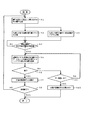
図2は図1の送信者端末1及び受信者端末2の動作を示すフローチャートである。これら図1及び図2を参照して送信者端末1及び受信者端末2における暗号化鍵生成処理及び相互認証処理について説明する。
FIG. 2 is a flowchart showing operations of the
送信者端末1及び受信者端末2各々は、鍵生成部11,21にて自立して暗号化のための鍵を生成し(図2ステップS1)、生成した暗号化鍵を暗号鍵メモリ13,23に記憶するとともに(図2ステップS2)、その生成した暗号化鍵の一部を認証用メモリ12,22に記憶する(図2ステップS3)。
Each of the
暗号化鍵の生成は、暗号鍵生成チャネル101を介して行われ、生成された暗号化鍵は予め設定された方法(例えば、10回生成された暗号化鍵のうちの9個を暗号用として用い、1個を認証用として用いる方法等)で規則性を持って暗号鍵メモリ13,23及び認証用メモリ12,22に記憶される。
Encryption key generation is performed via the encryption
暗号鍵メモリ13,23に記憶された暗号化鍵は、暗号化/復号化部14,24にてデータの暗号化及び復号化に用いられ、暗号化されたデータによる暗号化通信は暗号化通信路200を介して行われる。
The encryption keys stored in the encryption
認証用メモリ12,22に記憶された暗号化鍵の一部は、送信者端末1及び受信者端末2が再接続された際に(図2ステップS4)、認証チャネル102を介して送信者端末1及び受信者端末2の相互認証に用いられる。この相互認証は送信者端末1から受信者端末2への暗号化鍵の送信と、受信者端末2から送信者端末1への暗号化鍵の送信とを行って実現される。
A part of the encryption key stored in the
送信者端末1及び受信者端末2の相互認証は認証用メモリ12,22に記憶された鍵の全データもしくは過去の任意のタイミングで生成された鍵を比較することによって実現される(図2ステップS5)。その場合には、その比較で一致となった時に(図2ステップS6)、正規の接続相手と見做す(図2ステップS7)。また、その比較でN回、不一致になった場合には(図2ステップS6,S9)、正規の接続相手と見做さなず(図2ステップS10)、処理終了となる。
Mutual authentication of the
このように、本実施例では、認証用メモリ12,22に記憶された暗号化鍵の一部を用いて送信者端末1及び受信者端末2の相互認証を行うことで、偽伝送路を介して偽の受信者端末が接続される場合(図10参照)、あるいは伝送路上に偽の受信者端末及び偽の送信者端末が挿入された場合でも[図11(b)参照]、それら偽の装置を検出することができる。尚、一度認証に用いた鍵は破棄し、二度と認証用に用いないようにすることによって、相互接続の安全性を高めることができる。
As described above, in this embodiment, the mutual authentication of the
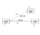
図3は本発明の第2の実施例による乱数生成共有システムの構成を示すブロック図である。図3において、本発明の第2の実施例による乱数生成共有システムでは、送信者端末1と受信者端末2とを工場出荷時に、工場等(暗号化鍵の生成や蓄積が管理可能な閉じた空間であればよい)にて上述した本発明の第1の実施例と同様の方法で暗号化鍵を生成し、それらを認証用メモリ12,22に蓄積しておき、送信者端末1と受信者端末2とを設置場所A,Bに設置し、光ファイバ201で接続した後、認証用メモリ12,22の暗号化鍵を用いて通信相手の認証を行っている。この場合、認証用メモリ12,22には、最初の認証に用いられる暗号化鍵が少なくとも蓄積される。
FIG. 3 is a block diagram showing the configuration of a random number generation sharing system according to the second embodiment of the present invention. In FIG. 3, in the random number generation sharing system according to the second embodiment of the present invention, the
また、本実施例では、送信者端末1と受信者端末2とが設置場所A,Bに設置された際に、光ファイバ201で接続できない場合でも、暗号鍵メモリ13,23に蓄積された暗号化鍵を用いた暗号通信を、IP(Intermet Protocol)網202を介して行うことができる。この場合、認証用メモリ12,22には認証用としても使用可能で、かつ暗号通信にも使用可能な汎用の暗号化鍵を蓄積しておいてもよい。
Further, in the present embodiment, when the
その際、IP網202では認証用の暗号化鍵を生成することができないので、認証用メモリ12,22には、所定期間(例えば、半年や一年)、使用可能な数だけ生成された認証用の暗号化鍵が蓄積される。但し、蓄積された暗号化鍵を全て使いきると、再度、送信者端末1と受信者端末2とを工場(管理可能な閉じた空間)に戻して暗号化鍵の生成及び蓄積が行われるが、認証用メモリ12,22のみを入替える方法も考えられる。
At this time, since the encryption key for authentication cannot be generated in the
図4は本発明の第3の実施例による乱数生成共有システムの構成を示すブロック図である。図4において、本発明の第3の実施例による乱数生成共有システムは送信者端末3と、受信者端末4とから構成されている。
FIG. 4 is a block diagram showing the configuration of a random number generation sharing system according to the third embodiment of the present invention. In FIG. 4, the random number generation and sharing system according to the third embodiment of the present invention includes a
送信者端末3は量子暗号鍵生成部31と、認証用メモリ32と、暗号鍵メモリ33とから構成され、受信者端末4は量子暗号鍵生成部41と、認証用メモリ42と、暗号鍵メモリ43とから構成されている。
The
送信者端末3及び受信者端末4は暗号鍵生成伝送路300によって相互に接続されており、暗号鍵生成伝送路300は暗号鍵生成チャネル301と認証チャネル302とから構成されている。
The
図5は図4に示す送信者端末3の量子暗号鍵生成部31の構成を示すブロック図であり、図6は図4に示す受信者端末4の量子暗号鍵生成部41の構成を示すブロック図である。
FIG. 5 is a block diagram showing a configuration of the quantum encryption
図5において、送信者端末3の量子暗号鍵生成部31はPlug&Playと呼ばれる構成となっており、ファラデーミラー311と、位相変調器312と、乱数発生部313と、基底発生部314とから構成されている。
In FIG. 5, the quantum encryption
図6において、受信者端末4の量子暗号鍵生成部41もPlug&Playと呼ばれる構成となっており、偏光ビームスプリッタ411と、光子検出器412,413と、位相変調器414と、基底発生部415と、光カプラ416と、光サーキュレータ417と、パルス光源418とから構成されている。
In FIG. 6, the quantum encryption key generation unit 41 of the
本実施例による送信者端末3及び受信者端末4の接続時の相互認証は、上述した本発明の第1の実施例と同様に、認証用メモリ32,42に記憶した鍵を用いて行われる。
Mutual authentication at the time of connection of the
これら図4〜図6を参照して本発明の第3の実施例による乱数生成共有システムの動作について説明する。送信者端末3及び受信者端末4は、暗号化のための鍵を量子暗号鍵生成部31,41にて自立して生成し、生成した鍵を暗号鍵メモリ33,43に記憶するとともに、その生成した鍵の一部を認証用メモリ32,42に記憶する。暗号化のための鍵の生成は、暗号鍵生成チャネル301を介して行われる。また、暗号化のための鍵の生成は、Plug&Play量子暗号鍵生成技術とBB84(Bennett Brassard 84)プロトコルとを用いて行われる。
The operation of the random number generation sharing system according to the third embodiment of the present invention will be described with reference to FIGS. The
図7は本発明の第3の実施例による量子暗号鍵生成処理を示すシーケンスチャートである。これら図4及び図7を参照して本発明の第3の実施例による量子暗号鍵生成処理について説明する。 FIG. 7 is a sequence chart showing the quantum key generation process according to the third embodiment of the present invention. With reference to FIGS. 4 and 7, the quantum key generation process according to the third embodiment of the present invention will be described.
ここで、量子チャネルとは送信者端末3から受信者端末4へ送信する光パワーが1photon/bit以下の微弱な状態の通信チャネルを示し、古典チャネルとは通常の光パワー領域での通信チャネルを示している。
Here, the quantum channel indicates a weak communication channel in which the optical power transmitted from the
この量子暗号鍵生成は、
(1)送信者端末3で暗号鍵の元データとなるランダムデータビット(a)と、変調時の基底(+基底、X基底)[基底情報(a)]となるランダムデータによって位相変調データを生成して記憶する(図7ステップS11)。
(2)送信者端末3で光パルスを位相変調データによって位相変調し、量子チャネルを介して受信者端末4に送信する(図7ステップS12,a1)。
(3)受信者端末4でもランダムな基底(+基底、X基底)データに基づいて送信者端末3からの光パルスを位相変調し、干渉計を経て受信する(図7ステップS21)。
(4)受信者端末4で受信することができた光データビット(b)とその時の基底とを記憶し[基底情報(b)]、送信者端末3へ古典チャネルを介して送信する(図7ステップS22,a2)。
(5)送信者端末3では受信者端末4から送られた基底情報(b)と記憶していた基底情報(a)とを比較し、ランダムデータビット(a)のうちの基底の合わないビットを破棄する(図7ステップS13)。
(6)送信者端末3から受信者端末4へ、ランダムデータビット(a)のうちの破棄されずに残ったビットのビット番号を古典チャネルを介して送信する(図7ステップS14,a3)。
(7)受信者端末4では送信者端末3から送られてきたビット番号以外の光データビット(b)を破棄する(図7ステップS23)。
(8)送信者端末3と受信者端末4とは暗号化鍵データを共有する(図7のa4)。
This quantum key generation is
(1) The phase-modulated data is generated by the random data bit (a) that is the original data of the encryption key at the
(2) The optical pulse is phase-modulated by the phase modulation data at the
(3) The
(4) The optical data bit (b) that can be received by the
(5) The
(6) The bit number of the remaining bits out of the random data bits (a) is transmitted from the
(7) The
(8) The
本実施例では、上述した本発明の第1の実施例と同様に、認証用メモリ32,42に記憶した鍵を、送信者端末3と受信者端末4とを接続した際に認証チャネル302を介して送信者端末3及び受信者端末4の相互認証に用いている。送信者端末3及び受信者端末4の相互認証は、認証用メモリ32,42に記憶した鍵の全データもしくは過去の任意のタイミングで生成された鍵を比較し、その比較で不一致となった時に、正規の接続相手と見做さないことによって実現される。
In the present embodiment, as in the first embodiment of the present invention described above, the
図8は本発明の第4の実施例による乱数生成共有システムの構成を示すブロック図である。図8において、本発明の第4の実施例による乱数生成共有システムは送信者端末5と、受信者端末(a,b)6,7とから構成されている。尚、図7においては送信者端末5及び受信者端末(a,b)6,7の暗号鍵生成部51,61,71と、認証用メモリ52,53,62,72と、暗号鍵メモリ54,55,63,73とについてのみ記載している。
FIG. 8 is a block diagram showing the configuration of a random number generation sharing system according to the fourth embodiment of the present invention. In FIG. 8, the random number generation and sharing system according to the fourth embodiment of the present invention comprises a
本実施例は、上述した本発明の第3の実施例と同様に、暗号鍵生成に量子暗号鍵生成技術を用いている。また、本構成例は1:2接続の例を表しており、送信者端末5と暗号鍵生成伝送路400,500と受信者端末(a,b)6,7とから構成されている。
In the present embodiment, a quantum encryption key generation technique is used for generating an encryption key, as in the third embodiment of the present invention described above. Further, this configuration example represents an example of 1: 2 connection, and includes a
送信者端末5は量子暗号鍵生成部51と、受信者端末6との間で生成した鍵の記憶に用いる認証用メモリ(a)52及び暗号鍵メモリ(a)54と、受信者端末7との間で生成した鍵の記憶に用いる認証用メモリ(b)53及び暗号鍵メモリ(b)55とから構成されている。
The
受信者端末(a)6は量子暗号鍵生成部61と、認証用メモリ62と、暗号鍵メモリ63とから構成され、受信者端末(b)7は量子暗号鍵生成部71と、認証用メモリ72と、暗号鍵メモリ73とから構成されている。
The receiver terminal (a) 6 includes a quantum key generation unit 61, an authentication memory 62, and an encryption key memory 63. The receiver terminal (b) 7 includes a quantum
送信者端末5と受信者端末(a)6とは暗号鍵生成伝送路400によって接続され、暗号鍵生成伝送路400は暗号鍵生成チャネル401と認証チャネル402とから構成されている。同様に、送信者端末5と受信者端末(b)7とは暗号鍵生成伝送路500によって接続され、暗号鍵生成伝送路500は暗号鍵生成チャネル501と認証チャネル502とから構成されている。
The
量子暗号鍵生成部51,61,71各々は上述した本発明の第2の実施例と同様に、Plug&Playと呼ばれる構成となっている。
Each of the quantum
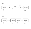
図9は本発明の第4の実施例における動作タイミングを示す図である。これら図8及び図9を参照して本発明の第4の実施例における動作タイミングについて説明する。 FIG. 9 is a diagram showing the operation timing in the fourth embodiment of the present invention. The operation timing in the fourth embodiment of the present invention will be described with reference to FIGS.
図9に示すように、送信者端末5と受信者(a,b)6,7とは暗号化鍵生成を時分割方式によって行っている。割り当てられたタイムスロット毎に鍵生成を行う以外の各々の鍵生成プロセスは上述した本発明の第2の実施例と同様である。また、受信者(a,b)6,7各々が送信者端末5と接続する際の相互認証についても、上述した本発明の第2の実施例と同様の動作となる。
As shown in FIG. 9, the
以上の説明では、量子暗号鍵生成方式をPlug&Play方式を用いて説明したが、PLC(Planar Light Circuit)を用いた方式でも構わない、暗号鍵生成プロトコルをBB84プロトコルとしたが、E91(Ekert 91)プロトコルでも、B92(Bennett 92)プロトコルでも構わない。 In the above description, the quantum key generation method has been described using the Plug & Play method. However, a method using PLC (Planar Light Circuit) may be used, and the encryption key generation protocol is the BB84 protocol, but E91 (Ekatet 91) Protocol or B92 (Bennett 92) protocol may be used.
また、本発明の第4の実施例では1:2接続を例に挙げて説明しているが、その接続形態は1:多(3以上)でも構わず、トポロジーもリングやバス型でも構わない。 In the fourth embodiment of the present invention, a 1: 2 connection is described as an example. However, the connection form may be 1: multiple (3 or more), and the topology may be a ring or bus type. .
このように、上記の構成において、上記の各機能を満たす限り、暗号鍵生成方式や暗号鍵生成プロトコル、接続形態は自由であり、上記の説明が本発明を限定するものではない。 As described above, in the above configuration, as long as the above functions are satisfied, the encryption key generation method, the encryption key generation protocol, and the connection form are free, and the above description does not limit the present invention.
本発明は、ネットワークを介して取引を行う際の秘匿通信システムや官庁等における重要情報の秘匿通信システム等の高度な安全性が要求される分野に適用することが可能である。 INDUSTRIAL APPLICABILITY The present invention can be applied to fields requiring a high level of security, such as a secret communication system when performing transactions via a network and a secret communication system for important information in government offices.
1,3,5 送信者側の暗号化通信装置
2,4,6,7 受信者側の暗号化通信装置
11,21 鍵生成部
12,22,32,42,52,
53,62,72 認証用メモリ
13,23,33,43,54,
55,63,73 暗号鍵メモリ
14,24 暗号化/復号化部
31,41 量子暗号鍵生成部
51,61,71 暗号鍵生成部
100,300,400,500 暗号鍵生成伝送路
101,301,401,501 暗号鍵生成チャネル
102,302,402,502 認証チャネル
200 暗号化通信路
201 光ファイバ
202 IP網
311 ファラデーミラー
312,414 位相変調器
313 乱数発生部
314,415 基底発生部
411 偏光ビームスプリッタ
412,413 光子検出器
416 光カプラ
418 パルス光源
1,3,5 Sender side encrypted communication device
2, 4, 6, 7 Encrypted communication device on receiver side
11, 21
53, 62, 72
55, 63, 73 Encryption key memory
14, 24 Encryption / decryption unit
31, 41 Quantum cryptographic key generation unit
51, 61, 71 Encryption
200 Encrypted communication path
201 optical fiber
202 IP network
311 Faraday Mirror
312,414 phase modulator
313 Random number generator
314,415 Base generation part
411 Polarizing beam splitter
412,413 photon detector
416 Optical coupler
418 Pulsed light source
Claims (22)
前記送信者端末と前記受信者端末との間で過去に生成及び共有された暗号化鍵の一部を保持する保持手段を有し、
前記送信者端末と前記受信者端末との接続を解除して再接続した際に前記保持手段に保持された暗号化鍵の一部が前記送信者端末及び前記受信者端末にて相互に確認された時に前記暗号化鍵の生成を再開し、
前記暗号化鍵の生成及び共有に量子暗号鍵配布方式を用いることを特徴とする乱数生成共有システム。 A random number generation and sharing system that generates and shares random numbers between a sender terminal and a receiver terminal and uses the random number as an encryption key,
Holding means for holding a part of an encryption key generated and shared in the past between the sender terminal and the receiver terminal;
When the connection between the sender terminal and the receiver terminal is released and reconnected, a part of the encryption key held in the holding means is mutually confirmed by the sender terminal and the receiver terminal. Restart the generation of the encryption key when
A random number generation / sharing system using a quantum key distribution method for generating and sharing the encryption key .
前記送信者端末と前記受信者端末との間で過去に生成及び共有された暗号化鍵の一部を保持する保持手段を有し、
前記送信者端末と前記受信者端末との接続を解除して再接続した際に前記保持手段に保持された暗号化鍵の一部が前記送信者端末及び前記受信者端末にて相互に確認された時に前記暗号化鍵の生成及び当該暗号化鍵を用いた暗号化通信を再開することを特徴とする暗号化通信装置。 An encryption communication device that generates and shares a random number between a sender terminal and a receiver terminal, and uses the random number as an encryption key for encrypted communication,
Holding means for holding a part of an encryption key generated and shared in the past between the sender terminal and the receiver terminal;
When the connection between the sender terminal and the receiver terminal is released and reconnected, a part of the encryption key held in the holding means is mutually confirmed by the sender terminal and the receiver terminal. And an encryption communication apparatus that restarts the generation of the encryption key and the encrypted communication using the encryption key.
前記送信者端末と前記受信者端末との間で過去に生成及び共有された暗号化鍵の一部を保持手段に保持し、前記送信者端末と前記受信者端末との接続を解除して再接続した際に前記保持手段に保持された暗号化鍵の一部が前記送信者端末及び前記受信者端末にて相互に確認された時に前記暗号化鍵の生成を再開し、
前記暗号化鍵の生成及び共有に量子暗号鍵配布方式を用いることを特徴とする乱数生成共有方法。 A random number generation and sharing method that generates and shares a random number between a sender terminal and a receiver terminal, and uses the random number as an encryption key,
A part of the encryption key generated and shared in the past between the sender terminal and the receiver terminal is held in a holding unit, and the connection between the sender terminal and the receiver terminal is released and re-executed. Resuming generation of the encryption key when a part of the encryption key held in the holding means when connected is mutually confirmed at the sender terminal and the receiver terminal ;
A random number generation and sharing method, wherein a quantum encryption key distribution method is used for generation and sharing of the encryption key .
Priority Applications (2)
| Application Number | Priority Date | Filing Date | Title |
|---|---|---|---|
| JP2004020618A JP4200909B2 (en) | 2004-01-29 | 2004-01-29 | Random number generation and sharing system, encrypted communication device, and random number generation and sharing method used therefor |
| US11/043,232 US7899183B2 (en) | 2004-01-29 | 2005-01-27 | Random number generating and sharing system, encrypted communication apparatus, and random number generating and sharing method for use therein |
Applications Claiming Priority (1)
| Application Number | Priority Date | Filing Date | Title |
|---|---|---|---|
| JP2004020618A JP4200909B2 (en) | 2004-01-29 | 2004-01-29 | Random number generation and sharing system, encrypted communication device, and random number generation and sharing method used therefor |
Publications (2)
| Publication Number | Publication Date |
|---|---|
| JP2005217676A JP2005217676A (en) | 2005-08-11 |
| JP4200909B2 true JP4200909B2 (en) | 2008-12-24 |
Family
ID=34805594
Family Applications (1)
| Application Number | Title | Priority Date | Filing Date |
|---|---|---|---|
| JP2004020618A Expired - Fee Related JP4200909B2 (en) | 2004-01-29 | 2004-01-29 | Random number generation and sharing system, encrypted communication device, and random number generation and sharing method used therefor |
Country Status (2)
| Country | Link |
|---|---|
| US (1) | US7899183B2 (en) |
| JP (1) | JP4200909B2 (en) |
Cited By (1)
| Publication number | Priority date | Publication date | Assignee | Title |
|---|---|---|---|---|
| US9455827B2 (en) | 2013-08-01 | 2016-09-27 | Kabushiki Kaisha Toshiba | Communication apparatus, computer program product, and communication system |
Families Citing this family (23)
| Publication number | Priority date | Publication date | Assignee | Title |
|---|---|---|---|---|
| JP2006211343A (en) * | 2005-01-28 | 2006-08-10 | Renesas Technology Corp | Authentication method and its system |
| FR2889320B1 (en) * | 2005-07-27 | 2007-10-26 | Smartquantum Sa | OPTICAL TRANSMISSION SYSTEM AND DEVICE FOR RECEIVING OPTICAL SIGNAL |
| JP4829628B2 (en) * | 2005-10-31 | 2011-12-07 | 富士通株式会社 | Encryption method, encryption / decryption method, encryption device, encryption / decryption device, and communication system |
| WO2007088288A1 (en) * | 2006-02-03 | 2007-08-09 | Advanced Track & Trace | Authentication method and device |
| JP4885960B2 (en) * | 2006-07-26 | 2012-02-29 | 独立行政法人科学技術振興機構 | Secret communication method and secret communication device |
| JP5424008B2 (en) * | 2006-12-19 | 2014-02-26 | 日本電気株式会社 | Shared information management method and system |
| US20090296847A1 (en) * | 2008-05-27 | 2009-12-03 | Viasat, Inc. | Fault tolerant modem redundancy |
| JP2011130120A (en) * | 2009-12-16 | 2011-06-30 | Sony Corp | Quantum public key cryptosystem, key generation device, encryption device, decoder, key generating method, encryption method, and decoding method |
| KR20120039133A (en) | 2010-10-15 | 2012-04-25 | 삼성전자주식회사 | Apparatus and method that generates originality verification and certifies originality verification |
| US9338003B2 (en) * | 2013-06-18 | 2016-05-10 | Maxim Integrated Products, Inc. | Secure modules using unique identification elements |
| KR101446629B1 (en) * | 2013-07-17 | 2014-10-06 | 한국전자통신연구원 | Apparatus and method for secure data transmission in wireless communication system |
| US9036820B2 (en) * | 2013-09-11 | 2015-05-19 | At&T Intellectual Property I, Lp | System and methods for UICC-based secure communication |
| KR101491778B1 (en) * | 2013-11-27 | 2015-02-11 | 한국전자통신연구원 | Apparatus and method for secure data transmission using relay |
| JP6223884B2 (en) * | 2014-03-19 | 2017-11-01 | 株式会社東芝 | COMMUNICATION DEVICE, COMMUNICATION METHOD, AND PROGRAM |
| JP6203093B2 (en) | 2014-03-19 | 2017-09-27 | 株式会社東芝 | COMMUNICATION SYSTEM, COMMUNICATION DEVICE, COMMUNICATION METHOD, AND PROGRAM |
| KR101718782B1 (en) | 2015-01-23 | 2017-03-22 | 서울시립대학교 산학협력단 | Secure payment and authentification system having enhanced security with quantum crypyography |
| KR101718781B1 (en) * | 2015-01-23 | 2017-04-04 | 서울시립대학교 산학협력단 | Mobile device with quantum cryptography capability for secure moble commerce and authentification method therefor |
| KR101705244B1 (en) | 2015-01-23 | 2017-02-09 | 서울시립대학교 산학협력단 | Mobile commerce with quantum cryptography enhanced security and authentification method therefor |
| CN108270554B (en) * | 2016-12-30 | 2022-06-10 | 国民技术股份有限公司 | Terminal pairing method and system |
| CN107094076B (en) * | 2017-04-14 | 2018-09-25 | 江苏亨通问天量子信息研究院有限公司 | Secret communication method based on quantum true random number and communication system |
| US10979395B2 (en) * | 2019-04-16 | 2021-04-13 | Fortinet, Inc. | Automatic virtual private network (VPN) establishment |
| CN114172640B (en) * | 2020-09-11 | 2023-09-19 | 军事科学院系统工程研究院网络信息研究所 | Sequencing replacement secure communication method based on quantum distribution |
| CN112600666B (en) * | 2020-11-18 | 2022-04-26 | 中山大学 | Quantum secure communication method and device, computer equipment and storage medium |
Family Cites Families (18)
| Publication number | Priority date | Publication date | Assignee | Title |
|---|---|---|---|---|
| GB8621333D0 (en) * | 1986-09-04 | 1986-10-15 | Manitoba Telephone System | Key management system |
| JPH01165241A (en) | 1987-12-21 | 1989-06-29 | Mitsubishi Electric Corp | Cryptographic key sharing device |
| JPH046925A (en) | 1990-04-24 | 1992-01-10 | Mitsubishi Electric Corp | Cryptographic key common share system |
| JPH0575598A (en) | 1991-09-18 | 1993-03-26 | Matsushita Electric Ind Co Ltd | Key data sharing device |
| JP2883243B2 (en) * | 1992-06-11 | 1999-04-19 | ケイディディ株式会社 | Remote party authentication / encryption key distribution method |
| DE4317380C1 (en) * | 1993-05-25 | 1994-08-18 | Siemens Ag | Method for authentication between two electronic devices |
| JP3541522B2 (en) * | 1995-10-09 | 2004-07-14 | 松下電器産業株式会社 | Communication protection system and equipment between devices |
| JPH09128507A (en) * | 1995-11-02 | 1997-05-16 | Oki Electric Ind Co Ltd | Mutual certifying method |
| CA2265553C (en) * | 1996-09-05 | 2007-03-13 | Swisscom Ag | Quantum cryptography device and method |
| JP2000174747A (en) | 1998-12-07 | 2000-06-23 | Nippon Telegr & Teleph Corp <Ntt> | Quantum cryptography device |
| JP2000286841A (en) | 1999-03-30 | 2000-10-13 | Nec Corp | Key delivery means using quantum encryption |
| JP4389129B2 (en) | 1999-09-20 | 2009-12-24 | ソニー株式会社 | Information transmission system, information transmission device, information reception device, and information transmission method |
| JP3563012B2 (en) | 2000-05-15 | 2004-09-08 | 三菱電機インフォメーションシステムズ株式会社 | User authentication system and user authentication method |
| JP4849710B2 (en) * | 2000-10-06 | 2012-01-11 | パナソニック株式会社 | Encryption key distribution method and apparatus |
| ATE355674T1 (en) * | 2001-07-10 | 2006-03-15 | Mitsubishi Electric Corp | SHARED DATA REFINING DEVICE AND METHODS |
| JP4462806B2 (en) | 2002-02-22 | 2010-05-12 | 日本電気株式会社 | Quantum cryptographic key distribution system |
| US7080404B2 (en) * | 2002-04-01 | 2006-07-18 | Microsoft Corporation | Automatic re-authentication |
| JP2003318881A (en) | 2002-04-26 | 2003-11-07 | Toshiba Corp | Cryptographic key updating system, its method and access point |
-
2004
- 2004-01-29 JP JP2004020618A patent/JP4200909B2/en not_active Expired - Fee Related
-
2005
- 2005-01-27 US US11/043,232 patent/US7899183B2/en not_active Expired - Fee Related
Cited By (1)
| Publication number | Priority date | Publication date | Assignee | Title |
|---|---|---|---|---|
| US9455827B2 (en) | 2013-08-01 | 2016-09-27 | Kabushiki Kaisha Toshiba | Communication apparatus, computer program product, and communication system |
Also Published As
| Publication number | Publication date |
|---|---|
| JP2005217676A (en) | 2005-08-11 |
| US7899183B2 (en) | 2011-03-01 |
| US20050172129A1 (en) | 2005-08-04 |
Similar Documents
| Publication | Publication Date | Title |
|---|---|---|
| JP4200909B2 (en) | Random number generation and sharing system, encrypted communication device, and random number generation and sharing method used therefor | |
| US8650401B2 (en) | Network having quantum key distribution | |
| EP2555466B1 (en) | System for distributing cryptographic keys | |
| EP2356772B1 (en) | Quantum key distribution | |
| US9698979B2 (en) | QKD key management system | |
| US8855316B2 (en) | Quantum cryptography apparatus | |
| US7181011B2 (en) | Key bank systems and methods for QKD | |
| US11728980B2 (en) | System for secure data transmission in digital data transmission network using single-pass quantum key distribution system and method of key negotiation during operation of the system | |
| US8433066B2 (en) | Method for generating an encryption/decryption key | |
| US20120023336A1 (en) | System and method for designing secure client-server communication protocols based on certificateless public key infrastructure | |
| EP2003812A2 (en) | Method and device for managing cryptographic keys in secret communications network | |
| US20160112192A1 (en) | Incorruptible public key using quantum cryptography for secure wired and wireless communications | |
| CN110852745B (en) | Block chain distributed dynamic network key automatic updating method | |
| JP2011521581A (en) | Quantum key distribution with movable key devices | |
| KR20110057448A (en) | A method of user-authenticated quantum key distribution | |
| JPWO2004030270A1 (en) | Cryptographic communication device | |
| CN102065016A (en) | Message sending and receiving method and device, message processing method and system | |
| US9635003B1 (en) | Method of validating a private-public key pair | |
| US20220294618A1 (en) | Improvements to qkd methods | |
| CN102088352A (en) | Data encryption transmission method and system for message-oriented middleware | |
| CN112187460A (en) | Master-slave network-oriented root key hidden symmetric encryption algorithm | |
| Aizan et al. | Implementation of BB84 Protocol on 802.11 i | |
| ROMAN | SSL, KERBEROS AND THE LEIGHTON-MICALI PROTOCOL | |
| Lance et al. | What is Quantum Key Distribution (QKD)? |
Legal Events
| Date | Code | Title | Description |
|---|---|---|---|
| A131 | Notification of reasons for refusal |
Free format text: JAPANESE INTERMEDIATE CODE: A131 Effective date: 20080408 |
|
| A521 | Request for written amendment filed |
Free format text: JAPANESE INTERMEDIATE CODE: A523 Effective date: 20080609 |
|
| TRDD | Decision of grant or rejection written | ||
| A01 | Written decision to grant a patent or to grant a registration (utility model) |
Free format text: JAPANESE INTERMEDIATE CODE: A01 Effective date: 20080916 |
|
| A01 | Written decision to grant a patent or to grant a registration (utility model) |
Free format text: JAPANESE INTERMEDIATE CODE: A01 |
|
| A61 | First payment of annual fees (during grant procedure) |
Free format text: JAPANESE INTERMEDIATE CODE: A61 Effective date: 20080929 |
|
| R150 | Certificate of patent or registration of utility model |
Free format text: JAPANESE INTERMEDIATE CODE: R150 Ref document number: 4200909 Country of ref document: JP Free format text: JAPANESE INTERMEDIATE CODE: R150 |
|
| FPAY | Renewal fee payment (event date is renewal date of database) |
Free format text: PAYMENT UNTIL: 20111017 Year of fee payment: 3 |
|
| FPAY | Renewal fee payment (event date is renewal date of database) |
Free format text: PAYMENT UNTIL: 20121017 Year of fee payment: 4 |
|
| FPAY | Renewal fee payment (event date is renewal date of database) |
Free format text: PAYMENT UNTIL: 20131017 Year of fee payment: 5 |
|
| LAPS | Cancellation because of no payment of annual fees |