JP4200835B2 - Time correction system, time correction instruction device, pointer-type clock, and time correction method - Google Patents
Time correction system, time correction instruction device, pointer-type clock, and time correction method Download PDFInfo
- Publication number
- JP4200835B2 JP4200835B2 JP2003191996A JP2003191996A JP4200835B2 JP 4200835 B2 JP4200835 B2 JP 4200835B2 JP 2003191996 A JP2003191996 A JP 2003191996A JP 2003191996 A JP2003191996 A JP 2003191996A JP 4200835 B2 JP4200835 B2 JP 4200835B2
- Authority
- JP
- Japan
- Prior art keywords
- time
- pointer
- correction
- instruction
- time data
- Prior art date
- Legal status (The legal status is an assumption and is not a legal conclusion. Google has not performed a legal analysis and makes no representation as to the accuracy of the status listed.)
- Expired - Fee Related
Links
Images


Description
【0001】
【発明の属する技術分野】
本発明は、時刻修正システム、時刻修正指示装置、指針式時計、および時刻修正方法に関する。
【0002】
【背景技術】
従来、回転する指針の位置により時刻を表示するとともに、回転する日車により、この日車上の数字等で日付を表示する日付表示付指針式時計が知られている。この日付表示付指針式時計では、時計自体を駆動するために、銀電池等の一次電池が設けられている。このため、例えば、電池が切れて交換が必要な時には、時計を時計店に持ち込み、時計店は、時計の裏蓋を開けて電池を交換するとともに、指針の表示時刻と日車の表示日付とを調整していた。
【0003】
また、日付表示付指針式時計には、暦上1ヶ月が30日や31日等になったり、閏年が存在したりすることから、日車の表示日付を自動的に修正する、いわゆるオートカレンダ機能を有するものも開発されている。このような時計においても一次電池が用いられており、電池が切れた場合には、前述同様に電池交換を行うとともに時刻および日付を調整し、さらに、オートカレンダ機能の設定のために年月も調整していた。
これらのオートカレンダ機能の有無に関わらず、このような時計では、一般に、時刻、日付、年月の調整は、リューズやボタン等を操作することにより実施されていた。
【0004】
【発明が解決しようとする課題】
しかしながら、このような調整の作業は、比較的小さな部材であるリューズやボタン等を用いて実施しなければならないため面倒であり、調整作業が非常に繁雑となっていた。このため、電池交換を必要とする時計が多数持ち込まれた場合には、電池交換に伴う日時調整作業に相当の時間がかかり、使用者への返却が遅れることとなっていた。
【0005】
なお、オートカレンダ機能付きの時計では、前述したように、電池交換時には、年月の調整もしなければならず、リューズやボタンによる調整の機構や方法等が複雑になっていた。このため、この問題を改善すべく、例えば、特開平9−61555号公報には、時計の裏蓋の内側に日付修正専用の液晶表示装置やスイッチを設け、これらの液晶表示装置やスイッチを用いて正しい年月日を入力することにより、内部の日付修正用回路等を介して、時計の日車の表示日付を修正する技術が開示されている。
しかしながら、この場合には、日付修正用に別途液晶表示装置やスイッチを設けるため、液晶パネルや回路、押え板等の部材点数が増加して、時計のコスト高や大型化等に繋がるという問題があった。
また、静電気等の何らかの作用により日付情報を持ったカウンタの設定がリセットされ、電池交換以外の理由で日付を修正する場合でも、わざわざ裏蓋を開けて日付修正をしなければならず、作業効率が悪いという問題もあった。
【0006】
さらに、特開平11−190781号公報にも示すように、オートカレンダ機能を設けるためには、時分秒針と日車とを駆動する駆動装置を別々に設ける場合が多く、この場合には、時分秒針が午前0時であることを検出するためのスイッチを設ける必要があり、時計のサイズや、部品点数および組み立て作業にかかるコスト等の点で不利になっていた。
【0007】
また、特開平10−62567号公報には、時計の裏蓋内に、オートカレンダ機能設定用の設定部を設け、この設定部にカレンダ情報となる暦および時刻を鉛筆等で書き込むことにより、表示日時を修正するものが開示されている。しかしながら、この場合には、設定部を設けるためのスペースが必要となり、時計の小型化を阻害し、また、設定部を小さくすることも考えられるが、この場合には、設定しにくくなるという不具合を生じる。さらには、設定の方法が必ずしも簡便ではないため、マニュアル等を見る必然性を生じ、却って、作業が繁雑になる可能性があった。
【0008】
一方、日付修正用に、別途、特定のボタンを外装部分に設ける構成も考えられるが、この場合には、部材点数の増加によるコスト高の問題や、特に、デザインが優先される腕時計等の場合には、その外観を損ねるという問題があった。
【0009】
本発明の目的は、外装部分にボタン等を設ける等の変更を加えることなく、時計の大型化やコスト高を抑えた上で、簡単に時刻を修正できる時刻修正システム、時刻修正指示装置、指針式時計、および時刻修正方法を提供することにある。
【0010】
【課題を解決するための手段】
本発明に係る時刻修正システムは、少なくとも時刻表示用の指針を有する指針式時計と、少なくとも基準となる基準時刻データを有する時刻修正指示装置とを備える時刻修正システムであって、前記時刻修正指示装置は、前記基準時刻データを計時する計時手段と、前記指針式時計の指針が指示する指示時刻データが入力される時刻入力手段と、前記指針式時計に対し前記基準時刻データおよび指示時刻データを出力可能な通信手段とを備え、前記指針式時計は、前記時刻修正指示装置からの前記各データを受信可能な通信手段と、前記指針の駆動を制御する駆動制御手段と、受信した前記基準時刻データと指示時刻データとを比較する比較手段と、この比較手段での比較結果に基づいて指針の指示を基準時刻データに合わせる修正手段とを備えることを特徴とする。
【0011】
ここで、指針式時計としては、日車により日付を表示する機能を有する時計や、いわゆるオートカレンダ機能を有する時計、これらの日付表示機能のない時計等を採用できる。なお、指針とは、時針や分針、秒針等のことであり、その形状には、通常の針状のものに加えて、目盛が表記された円板状のもの等も含まれる。
【0012】
また、時刻修正指示装置としては、例えば、基準時刻データを計時するコンピュータ(PC)や、標準時刻情報を含む電波を受信して時刻修正を行う、いわゆる電波時計としての機能を有する装置等を採用できる。基準時刻データは、電話回線を介して入手したり、前述した標準時刻情報を含む電波を受信したり、携帯電話の電波に時刻情報が搭載されたサービス等を用いて入手したりできる。また、時刻修正指示装置内にクォーツ時計機能を設けて、この時計機能の時刻を基準時刻データとすることができる。
さらに、インターネット等の通信回線を介して、NTP(Network Time Protocol)等を用いて、コンピュータ等で構成された時刻修正指示装置の基準時刻を合わせる方法やサービスを利用することができる。
【0013】
ここで、指針を駆動する構成としては、例えば、一次電池等から電力によりステッピングモータ等の所定のモータを回転させ、この回転力を歯車の輪列等で伝達して一定速度で指針を駆動するもの等を採用できる。
また、通信手段としては、例えば、電磁誘導を用いたものや、赤外線通信、USB(Universal Serial Bus)およびSCSI等による電気的な接続による通信や、光通信、音波(超音波)通信その他の各種インターフェースを用いて実現できる。
【0014】
以上のような発明では、例えば、時計店の作業者は、指針式時計の裏蓋を開けて電池を交換した後に、指針式時計の通信手段と時刻修正指示装置の通信手段とを通信可能な状態、例えば、通信用の配線を接続した状態として、文字板上の指針を見ながら指示時刻を時刻修正指示装置の時刻入力手段から入力する。
すると、時刻修正指示装置では、この入力された指示時刻データと計時手段で計時されている基準時刻データとが、通信手段から指針式時計に対し出力される。
次に、指針式時計では、これらのデータが通信手段で受信され、これらの受信された基準時刻データおよび指示時刻データが比較手段で比較され、この比較結果に基づいて修正手段で指針の指示が基準時刻データに合わせられる。以上のようにして、指針式時計の時刻が修正される。
【0015】
本発明によれば、作業者は、指針式時計と時刻修正指示装置とを通信可能な状態とし、指針式時計の指示時刻を入力するだけで、後は、時刻修正指示装置および指針式時計において自動的に指示時刻が修正される。このため、作業者は、わざわざ、リューズやボタン等を操作することなく、簡単に時刻を修正でき、修正用の時計が沢山ある場合でも効率的に作業を行うことができる。
また、例えば、指針式時計において、通信手段として指針駆動用のモータのモータコイルを用い、かつ修正手段および比較手段を時計のIC部分に組み込むことにより、一般的な時計に比べても新たに部品を組み込む必要がないから、部品点数の増加を抑えることができて、時計を安価で製造できる。
さらに、データ受信用の通信手段および比較手段を設けるだけなので、液晶装置等を設ける場合に比べて、時計の大型化やコスト高を防止できるとともに、時計の外観構成等に大きな変更を加える必要もない。
【0016】
以上の時刻修正システムにおいて、前記指針式時計は、現在時刻をカウントする現時刻カウンタを備え、前記指針式時計の修正手段は、前記駆動制御手段の駆動に同期してカウントアップするとともに前記通信手段で受信した指示時刻データが入力される針位置カウンタと、前記現時刻カウンタでカウントされている基準時刻データと前記針位置カウンタでカウントされている指示時刻データとを比較してこの比較結果に基づく修正指示信号を前記駆動制御手段に入力する一致回路とを備えることが好ましい。
この場合には、指針式時計に現時刻カウンタを設け、さらに、指針式時計の修正手段に針位置カウンタおよび一致回路をソフトウェア的な構成として設けるだけなので、構成を簡単にできるとともに、指針式時計の小型化や軽量化を阻害しない。
【0017】
本発明に係る時刻修正システムは、少なくとも時刻表示用の指針を有する指針式時計と、少なくとも基準となる基準時刻データを有する時刻修正指示装置とを備える時刻修正システムであって、前記時刻修正指示装置は、前記基準時刻データを計時する計時手段と、前記指針式時計の指針が指示する指示時刻データが入力される時刻入力手段と、前記計時手段で計時されている基準時刻データと前記時刻入力手段で入力された指示時刻データとを比較する比較手段と、この比較結果に基づく修正指示信号を前記指針式時計に対して出力可能な通信手段とを備え、前記指針式時計は、前記時刻修正指示装置からの修正指示信号を受信可能な通信手段と、前記指針の駆動を制御する駆動制御手段と、受信した修正指示信号に基づいて指針の指示を基準時刻データに合わせる修正手段とを備えることを特徴とする。
【0018】
以上のような発明では、例えば、時計店の作業者は、指針式時計の裏蓋を開けて電池を交換した後に、指針式時計の通信手段と時刻修正指示装置の通信手段とを通信可能な状態、例えば、通信用の配線を接続した状態として、文字板上の指針を見ながら指示時刻を時刻修正指示装置の時刻入力手段から入力する。
すると、時刻修正指示装置では、この入力された指示時刻データと計時手段で計時されている基準時刻データとが比較手段で比較され、この比較結果に基づく修正指示信号が通信手段から指針式時計に対し出力される。
次に、指針式時計では、この修正指示信号が通信手段で受信され、この受信された修正指示信号に基づいて、修正手段で指針の指示が基準時刻データに合わせられる。以上のようにして、指針式時計の時刻が修正される。
【0019】
本発明によれば、作業者は、指針式時計と時刻修正指示装置とを通信可能な状態とし、指針式時計の指示時刻を入力するだけで、後は、時刻修正指示装置および指針式時計において自動的に指示時刻が修正される。このため、作業者は、わざわざ、リューズやボタン等を操作することなく、簡単に時刻を修正でき、修正用の時計が沢山ある場合でも効率的に作業を行うことができる。
【0020】
また、指針式時計に、データ受信用の通信手段を設けるだけなので、液晶装置等を設ける場合に比べて、時計の大型化やコスト高を防止できるとともに、時計の外観構成等に大きな変更を加える必要もない。
【0021】
この時刻修正システムにおいて、前記時刻修正指示装置の比較手段は、前記入力手段で入力された指示時刻データを記憶しこの指示時刻データを初期値としてカウントアップする針位置カウンタと、前記計時手段でカウントされている基準日時データと前記針位置カウンタでカウントされている値とを比較してこの比較結果に基づく修正指示信号を出力する一致回路とを備えることが好ましい。
この場合には、時刻修正指示装置の比較手段に針位置カウンタおよび一致回路をソフトウェア的な構成として設けることにより、比較的簡単に構成できる。このように、時刻修正指示装置側に針位置カウンタおよび一致回路を備えるため、時計側の構成を簡単なものにできる。
【0022】
以上において、指針式時計は、モータコイルを有し前記指針を駆動するモータを備え、前記モータコイルは、外部からのデータを受信する前記通信手段も兼ねていることが好ましい。モータとしては、ステッピングモータ等を採用できる。
この場合には、指針の駆動用に使用されているモータのモータコイルを用いて、外部からのデータを受信することにより、改めて、受信用のアンテナ部材等を時計内に組み込む必要がないから、時計のコスト低減および小型化を図ることができる。
【0023】
また、指針式時計は、前記駆動制御手段を駆動するための電力供給用の二次電池を備えることが好ましい。二次電池とは、発電機で発電されたエネルギを蓄えておく電池のことである。例えば、ソーラー充電方式や、自動巻き発電方式のものを採用できる。また、時刻修正指示装置から電力を導く等の外部充電方式等の各種の充電方式によって二次電池に指針式時計駆動用のエネルギを蓄えることができる。
このような二次電池を備えることにより、充電電圧が低下して指針が停止し、電池を充電して日付や時刻を修正する場合でも、裏蓋を開閉する作業が不要であるため、作業性を向上できる。
【0024】
以上において、前記時刻修正指示装置は、コンピュータにより構成され、前記時刻入力手段は、キーボードにより構成されていることが好ましい。
この場合には、時刻修正指示装置をコンピュータとして構成し、この際、時刻入力手段をキーボードとすることにより、修正を行う作業者にとって比較的なじみやすく操作性を向上できる。また、専用の時刻修正指示装置を構成する場合に比べて、コンピュータにプログラムを組み込むだけで簡単に時刻修正指示装置を構成できる。
【0025】
以上において、前記時刻入力手段で入力される指示時刻データは、前記指針が指示する少なくとも時、分、日であることが好ましく、このようにすれば、日車付きの一般的な指針式時計にも対応できる。
【0026】
本発明に係る指針式時計は、少なくとも時刻表示用の指針を有し、少なくとも基準となる基準時刻データを有する時刻修正指示装置により前記指針の指示が修正される指針式時計であって、該時計の指針が指示する時刻であって時刻入力手段により前記時刻修正指示装置に入力され、かつこの時刻修正指示装置から出力される指示時刻データと前記基準時刻データとを受信可能な通信手段と、前記指針の駆動を制御する駆動制御手段と、受信した前記基準時刻データと指示時刻データとを比較する比較手段と、この比較手段での比較結果に基づいて指針の指示を基準時刻データに合わせる修正手段とを備えることを特徴とする。
【0027】
本発明によれば、例えば、前述と同様の修正指示装置を用いることにより、指針式時計と時刻修正指示装置とを通信可能な状態とし、指針式時計の指示時刻を入力するだけで、自動的に指示時刻が修正されるため、リューズやボタン等を操作することなく、簡単に時刻を修正できて、作業を効率的に行うことができる。また、例えば、通信手段として指針駆動用のモータのモータコイルを用い、かつ修正手段および比較手段を時計のIC部分に組み込むことにより、一般的な時計に比べて新たな部品を組み込む必要がないから、部品点数の増加を抑えることができて、時計を安価で製造できる。
【0030】
本発明に係る時刻修正指示装置は、少なくとも基準となる基準時刻データを有し、この基準時刻データに基づいて、少なくとも時刻表示用の指針を有する指針式時計の指針の指示を修正させうる時刻修正指示装置であって、前記基準時刻データを計時する計時手段と、前記指針式時計の指針が指示する指示時刻データが入力される時刻入力手段と、前記指針式時計に対し前記基準時刻データおよび指示時刻データを出力可能な通信手段とを備えることを特徴とする。
【0031】
本発明によれば、例えば、前述と同様の指針式時計を用いることにより、指針式時計と時刻修正指示装置とを通信可能な状態とし、指針式時計の指示時刻を入力するだけで、自動的に指示時刻が修正されるため、リューズやボタン等を操作することなく、簡単に時刻を修正できて、作業を効率的に行うことができる。また、修正指示装置側には、比較手段を設けない構成としてので、修正指示装置の構成を簡単にできる。
【0032】
本発明に係る時刻修正指示装置は、少なくとも基準となる基準時刻データを有し、この基準時刻データに基づいて、少なくとも時刻表示用の指針を有する指針式時計の指針の修正信号を出力する時刻修正指示装置であって、前記基準時刻データを計時する計時手段と、前記指針式時計の指針が指示する指示時刻データが入力される時刻入力手段と、前記計時手段で計時されている基準時刻データ、および前記時刻入力手段で入力された指示時刻データを比較する比較手段と、この比較結果に基づく修正指示信号を前記指針式時計に対して出力可能な通信手段とを備えることを特徴とする。
【0033】
本発明によれば、例えば、前述と同様の指針式時計を用いることにより、作業者は、指針式時計と時刻修正指示装置とを通信可能な状態とし、指針式時計の指示時刻を入力するだけで、自動的に指示時刻が修正されるため、リューズやボタン等を操作することなく、簡単に時刻を修正でき、修正用の時計が沢山ある場合でも効率的に作業を行うことができる。
また、修正指示装置側に比較手段を設け、指針式時計側には比較手段を設けない構成としたので、指針式時計の構成を簡単にできて、時計の製造コストを抑えることができる。
【0034】
本発明に係る時刻修正方法は、少なくとも基準となる基準時刻データを有する時刻修正指示装置を用いて、少なくとも時刻表示用の指針を有する指針式時計の指針の指示を修正する時刻修正方法であって、前記時刻修正指示装置において、前記指針式時計の指針が指示する指示時刻データが入力される時刻入力手順と、前記指針式時計に対し前記基準時刻データおよび指示時刻データを出力する通信手順と、前記指針式時計において、前記出力された各データを受信する受信手順と、受信した前記基準時刻データ、および指示時刻データを比較する比較手順と、この比較手順での比較結果に基づいて指針の指示を基準時刻データに合わせる修正手順とを備えることを特徴とする。
【0035】
本発明によれば、前述同様に、指針式時計と時刻修正指示装置とを通信可能な状態とし、指針式時計の指示時刻を入力するだけで、自動的に指示時刻が修正されるため、リューズやボタン等を操作することなく、簡単に時刻を修正できて、作業を効率的に行うことができる。また、電池交換が必要ない場合には、裏蓋を開けなくても、時刻を修正できるので作業効率を向上できる。
また、このような方法において、例えば、指針式時計では、データ受信用の通信手段として指針駆動用のモータのモータコイルを用い、かつ修正手段および比較手段を時計のIC部分に組み込むことにより、一般的な時計に比べて新たな部品を組み込む必要がないから、部品点数の増加を抑えて時計を安価で製造できる。
【0036】
本発明に係る時刻修正方法は、少なくとも基準となる基準時刻データを有する時刻修正指示装置を用いて、少なくとも時刻表示用の指針を有する指針式時計の指針の指示を修正する時刻修正方法であって、前記時刻修正指示装置において、前記指針式時計の指針が指示する指示時刻データが入力される時刻入力手順と、この入力された指示時刻データ、および計時手段で計時されている基準時刻データを比較する比較手順と、この比較結果に基づく修正指示信号を前記指針式時計に対して出力する通信手順と、前記指針式時計において、前記出力された修正指示信号を受信する受信手順と、受信した修正指示信号に基づいて、前記指針の指示を基準時刻データに合わせる修正手順とを備えることを特徴とする。
【0037】
本発明によれば、前述同様に、指針式時計と時刻修正指示装置とを通信可能な状態とし、指針式時計の指示時刻を入力するだけで、自動的に指示時刻が修正されるため、リューズやボタン等を操作することなく、簡単に時刻を修正できて、作業を効率的に行うことができる。
また、例えば、通信手段として指針駆動用のモータのモータコイルを用い、かつ修正手段を時計のIC部分に組み込むことにより、一般的な時計に比べても新たに部品を組み込む必要がないから、部品点数の増加を抑えて、安価で時計を製造できる。
【0038】
【発明の実施の形態】
[第1実施形態]
以下、本発明に係る第1実施形態を図面に基づいて説明する。
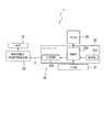
図1は、本発明の時刻修正システムである日時修正システムを示す図である。
日時修正システム1は、図1に示すように、日付表示機能を有する指針式時計としての時計10と、この時計10の表示時刻および日付(日時)を修正する時刻修正指示装置としての修正指示装置20とを備える。
【0039】
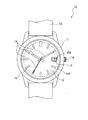
図2は、時計10の表示部分を示す図である。
時計10は、腕時計型の時計であり、表裏面が開口され環状筐体で樹脂または金属製の本体ケース11と、この本体ケース11の表面側開口部11Aに取りつけられる風防ガラス12と、図示を省略するが、本体ケース11の裏面側開口部に取りつけられる裏蓋と、本体ケース11に取りつけられ、使用者の手首等へ装着するためのバンド13とを備える。
【0040】
図2では図示を一部省略するが、本体ケース11内には、時計の本体部分となるムーブメントと、このムーブメントに一端が接続され、その他端が本体ケース11の側部から露出する巻真とが設けられている。巻真の他端には、時刻修正用の竜頭14が設けられている。竜頭14は、本体ケース11の側部に位置する。
【0041】
また、本体ケース11内には、風防ガラス12の内側に位置し、日時を表示するための文字板15と、この文字板15および風防ガラス12の間で回転する指針16と、リング状の日車17とが設置されている。
日車17の表面側には、1〜31までの日付表示用の数字が表記されている。また、文字板15の一部には、この日付表示用の数字を外部に表示するための日窓15Aが形成されている。
【0042】
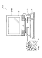
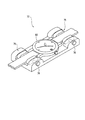
図3は、時計10のムーブメントの構成を示す図である。図4は、主に、このムーブメントの機能を示すブロック図である。
図3に示すように、ムーブメント30は、銀電池等の一次電池31と、この一次電池31からの電力により全体の駆動を制御する制御部32と、輪列部33Aを介して時刻表示用の指針16を回転させるモータとしてのステッピングモータ33と、輪列部34Aを介して日付表示用の日車17を回転させる圧電アクチュエータ34と、制御部32からの駆動制御信号を受けて圧電アクチュエータ34を駆動する日車駆動部35とを備える。
【0043】
ステッピングモータ33は、モータコイル331と、パーマロイ材等からなるステータ332と、ロータ333とを備え、モータコイル331において、制御部32から出力されたパルス信号Aを受け、この受けたパルス信号Aを、ステータ332およびロータ333を介して磁気さらには回転運動へと変換して、輪列部34Aの回転を制御するものである。また、このステッピングモータ33のモータコイル331は、日時修正用のデータを受信(検出)する受信手段としても使用される。
【0044】
輪列部33Aは、大小複数の歯車から構成され、これらの歯車により、ロータ333の回転運動を所定回転数の回転に変換し伝達するものである。
指針16は、輪列部33Aの歯車に取りつけられ、各歯車とともに一定速度で回転して、文字板15に基づいて時刻を示す針であり、秒針16Aと、分針16Bと、時針16Cとを備える。
【0045】
日車駆動部35は、制御部32から出力された駆動制御信号Bを受けて、圧電アクチュエータ34に所定電圧を印加するものである。
圧電アクチュエータ34は、日車駆動部35からの印加電圧を受けて変形し、その曲面状の先端に当接された輪列部34Aが回転し、日車17の回転が制御される。
【0046】
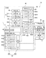
図4に示すように、制御部32は、発振回路40と、駆動制御手段41と、カウンタ42と、通信手段としての外部信号検出回路43と、時刻修正制御回路44とを備える。
【0047】
発振回路40は、水晶振動子からなる基準発振源を有し、基準パルスを出力するものである。
駆動制御手段41は、指針16の駆動を制御するものであり、発振回路40から出力された基準パルスを入力し、この基準パルスに基づいて種々の周波数のパルスを生成する分周回路411と、この分周回路411から出力されたパルスに基づいて、ステッピングモータ33を駆動するモータ駆動パルスを発生するパルス発生回路412とを備える。また、分周回路411は、時刻修正制御回路44から入力された信号に基づいて、パルス発生回路412に、所定周波数のパルスを出力する。例えば、分周回路411は、1Hzのパルスまたは256Hzのパルスに切り替えられて、通常の運針用のパルスや早送り用のパルスを出力する。
【0048】
カウンタ42は、分周回路411から入力された基準パルスに基づいて現時刻をカウントする現時刻カウンタ421と、この現時刻カウンタ421の値に基づいて暦をカウントする暦カウンタ422とを備える。
【0049】
現時刻カウンタ421は、現在時刻をカウントすることにより日付変更タイミングをとる機能を有するカウンタであり、時刻のうち秒をカウントする秒カウンタ421Aと、分をカウントする分カウンタ421Bと、時をカウントする時カウンタ421Cとを備える。
【0050】
秒カウンタ421Aは、分周回路411から出力された1Hzのパルスをカウントするものであり、60秒でループするカウンタである。
分カウンタ421Bは、秒カウンタ421Aのループに基づく信号を入力してカウントを行うものであり、60分でループするカウンタである。
時カウンタ421Cは、分カウンタ421Bのループに基づく信号を入力してカウントを行うものであり、24時間でループするカウンタである。
【0051】
暦カウンタ422は、年月日をカウントすることにより日付表示を月末も含め正確に修正するカウンタであり、日付のうち日をカウントする日カウンタ422Aと、月をカウントする月カウンタ422Bと、年をカウントする年カウンタ422Cとを備える。
【0052】
日カウンタ422Aは、時カウンタ421Cのループに基づく信号を入力してカウントを行うものであり、31日でループするカウンタである。
月カウンタ422Bは、日カウンタ422Aのループに基づく信号を入力してカウントを行うものであり、12月でループするカウンタである。
年カウンタ422Cは、月カウンタ422Bのループに基づく信号を入力してカウントを行うものであり、閏年ごと、すなわち4年でループするカウンタである。この場合には、修正指示装置20側において、閏年から何年目か等の計算を行い、時計10は、この計算結果を受信し、この計算結果に基づいて0〜3のいずれかをセットする構成とすることができる。なお、年カウンタ422Cを9999年でループするカウンタとしてもよい。
【0053】
日車駆動部35は、日カウンタ422Aから出力された信号に基づいて、圧電アクチュエータ34を駆動するものであり、この圧電アクチュエータ34により、輪列部34Aを介して日車17が駆動する。日車駆動部35は、圧電アクチュエータ34によって、一日分の日送りがされたか否かを検出する日車送り検出回路351を備える。
【0054】
外部信号検出回路43は、修正指示装置20等の外部の装置から出力されたデータ(後述する指示日時データや、基準時刻データ、基準日付データ)を、ステッピングモータ33のモータコイル331を介して受信し、この受信したデータを波形整形しデジタル信号に変換して、時刻修正制御回路44へ出力する。
【0055】
時刻修正制御回路44は、外部信号検出回路43から入力されたデータの一部を記憶するとともに、残りの他のデータを現時刻カウンタ421および暦カウンタ422に書き込み、時計10の指示する時刻および日付を修正するものである。時刻修正制御回路44は、針位置カウンタ441と、一致回路442とを備える。また、時刻修正制御回路44は、時刻修正を行う際に、指針16の駆動(運針)を止めるとともに、分周回路411の低周波側、例えば、128Hzより低い周波数をリセットする機能を有する。
【0056】
針位置カウンタ441は、外部信号検出回路43からの指示日時データ(日、時、分、秒)を入力し、この入力された指示日時データを初期値として、ステッピングモータ33の駆動に同期してカウントアップするものであり、時刻のうち秒をカウントする秒カウンタ441Aと、分をカウントする分カウンタ441Bと、時をカウントする時カウンタ441Cと、日をカウントする日カウンタ441Dとを備える。
【0057】
秒カウンタ441Aは、60秒でループするカウンタである。
分カウンタ441Bは、秒カウンタ441Aのループに基づく信号を入力してカウントを行うものであり、60分でループするカウンタである。
時カウンタ441Cは、分カウンタ441Bのループに基づく信号を入力してカウントを行うものであり、24時間でループするカウンタである。
日カウンタ441Dは、日車駆動部35の日車送り検出回路351での検出に基づく信号を入力してカウントするものであり、31日でループするカウンタである。
【0058】
一致回路442は、現時刻カウンタ42でカウントされている基準時刻データと、針位置カウンタ441でカウントされている指示時刻データとを比較して、この比較結果に基づく修正指示信号を駆動制御手段41に入力し、この入力された修正指示信号に基づいて、分周回路411は、パルス発生回路412から出力されるパルスを早送り用の周波数のものに切り替え、パルス発生回路412は、切り替えられた早送り用のパルスをステッピングモータ33へ出力する。この際、ステッピングモータ33は、この早送り用のパルスを受けて指針16を早送りする。また、秒カウンタ441Aは、パルス発生回路412からのパルス出力信号またはパルス発生の元となる分周回路411からのパルス発生命令信号に基づいてカウントアップされる。
【0059】
また、一致回路442は、比較結果に基づく修正信号を日車駆動部35に出力し、この信号を受けた日車駆動部35は、圧電アクチュエータ34を駆動する早送り用の信号を出力して日車17を早送りする。この際、日送り検出回路351は、日車17の駆動を検出するとともに、この検出結果を日カウンタ441Dに出力し、検出結果を入力した日カウンタ441Dは、カウントアップする。
このような一致回路442は、最終的に両データの比較結果が一致するまで、上述した動作を繰り返す。
なお、駆動制御手段41および日車駆動部35は、修正手段として機能している。また、時刻修正制御回路44およびカウンタ42は、比較手段として機能している。
【0060】
図1に戻って、修正指示装置20は、文字等の入力に用いられる入力手段としてのキーボード21と、CPUやハードディスク等を含むコンピュータ本体22と、入力された文字等を表示する表示部としてのモニタ23と、時計10が設置されるクレードル様の時計設置台24とを備える。なお、コンピュータ本体22と時計設置台24とは、電気的に接続されている。
【0061】
図5は、修正指示装置20の機能を示すブロック図である。
キーボード21は、図1,5に示すように、時計10の指針16が指示する指示時刻データおよび日車17が指示する日付データが入力される時刻入力手段(入力部)として機能する。
【0062】
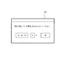
図6は、キーボード21から指示時刻データおよび指示日付データが入力された際に、モニタ23に表示された画面を示す図である。例えば、図6に示すように、キーボード21では、指示時刻データとして12時58分59秒(12:58:59)が入力され、また、指示日付データとして4日が入力される。
【0063】
図5に戻って、コンピュータ本体22は、基準となる日時を示す基準日時データを計時する計時手段としての計時部221と、コンピュータ全体の制御を行う制御部222と、計時部221の基準日時データや、入力された指示時刻データおよび指示日付データを外部出力可能なデータ信号Pに変換するインターフェース回路(I/F回路)223とを備える。
【0064】
時計設置台24は、コイルを内蔵する磁界発生回路等により構成され、I/F回路223から出力されたデータ信号Pを、設置された時計10に対して出力する通信手段として機能するクレードル様の台である。
【0065】
図7は、時計店において、時計の日時を修正する手順を示すフロー図である。まず、時計店の作業者は、時計10の裏蓋を外して中から一次電池31を取り出し、電池を新しい電池に交換する(処理S1)。この電池交換と同時に、現時刻カウンタ421および暦カウンタ422はリセットされ(処理S2)、時計10は、通常通りに、1秒ごとの運針を開始する(処理S3)。
【0066】
次に、作業者は、時計10を時計設置台24に設置し、修正指示装置20の日時修正プログラムを起動させると(処理S4)、修正指示装置20では、通信手段である時計設置台24から日時修正スタートの信号が時計10に送信される(処理S5)。一方、時計10では、外部信号検出回路43により、この日時修正スタートの信号が受信された後に(処理S6)、運針は、分周回路411内部の、1Hzをカウントするための128Hz以下の分周回路411がリセットされた状態で停止する。(処理S7)。
【0067】
次に、修正指示装置20では、モニタ23に「時計の表示している時刻および日付を入力してください」と表示される(処理S8)。これに対して、作業者は、キーボード21から、時計10の表示時刻である指示時刻データおよび表示日付である指示日付データ(表示情報)を入力する(時刻入力手順)。
【0068】
次に、修正指示装置20では、キーボード21で入力された時計10の指示時刻データおよび指示日付データが時計10へ送信されるとともに、計時部221でカウントされている基準日時データ(現在の年月日、時分秒情報)が時計10に送信される(処理S9:通信手順)。
【0069】
時計10では、外部信号検出回路43により、修正指示装置20から出力された指示時刻データ(時分秒)や指示日付データ(日)、基準日時データ(現在の年月日、時分秒情報)が受信される(処理S10:受信手順)。その後、時計10では、時刻修正制御回路44により、基準日時データのうちの基準時刻データ(現在の時分秒)が現時刻カウンタ421にセットされ、また、基準年月日データ(現在の年月日)が暦カウンタ422にセットされる(処理S11)。
【0070】
次に、時計10では、時刻修正制御回路44により、1Hz(秒)をカウントする分周回路411がスタートし、これにより、現時刻カウンタ421は、カウントを開始する(処理S12)。
【0071】
また、時計10では、時刻修正制御回路44により、針位置カウンタ441に、修正指示装置20から受信した指示時刻データ(時分秒)および指示日付データ(日)がセットされる(処理S13)。
【0072】
次に、時計10では、一致回路442により、針位置カウンタ441の日カウンタ441Dの値と、暦カウンタ422の日カウンタ422Aの値とが比較されて、この比較結果に基づく修正指示信号に基づいて、日車駆動部35は、圧電アクチュエータ34を駆動する早送り用の信号(日送り用アクチュエータ駆動パルス)を出力して日車17を早送りする(処理S14:比較手段,修正手段)。この送り結果に基づいて、日送り検出回路351は、日車17の駆動を検出するとともに、この検出結果を日カウンタ441Dに出力して日カウンタ441Dをカウントアップする。このような動作を、両データの比較結果が一致するまで繰り返す(処理S15)。
【0073】
また、一致回路442により、針位置カウンタ441の各カウンタ441A〜441Cの値と、現時刻カウンタ421の各カウンタ421A〜421Cの値とが比較されて、この比較結果に基づく修正指示信号に基づいて、分周回路411は、パルス発生回路412から出力されるパルスを早送り用の周波数のものに切り替え、パルス発生回路412は、切り替えられた早送り用のパルス(モータ早送りパルス)をステッピングモータ33へ出力する(処理S16:比較手段,修正手段)。この際、ステッピングモータ33は、このモータ早送りパルスを受けて指針16を早送りするとともに、時刻修正制御回路44の秒カウンタ441Aをカウントアップする。このような動作を、両データの比較結果が一致するまで繰り返す(処理S17)。
【0074】
以上により、時計10は、時刻および日付ともに修正され、通常の運針状態に復帰する(処理S18)。修正指示装置20では、モニタ23に「現在時刻への修正が終わりました」と表示され(処理S19)、時刻修正プログラムが終了する(処理S20)。最後に、作業者は、時計設置台24の通信状態から時計10を開放して、次の時計を時計設置台24にセットし、続けて時刻および日付の修正を行う。
【0075】
本実施形態によれば、以下のような効果が得られる。
(1)作業者は、時計10と修正指示装置20とを通信可能な状態とし、時計10の指示時刻を入力するだけで、修正指示装置20および時計10において自動的に指示時刻,日付が修正される。このため、作業者は、わざわざ竜頭やボタン等を操作しなくても、簡単に時刻および日付を修正でき、修正用の時計10が沢山ある場合であっても、効率よく作業を実施できる。
【0076】
(2)指針16の駆動に使用されるステッピングモータ33のモータコイル331を用いて、外部からのデータを受信することにより、改めて、受信用の部材を時計10内に組み込む必要がないから、時計のコスト低減および小型化を図ることができる。
【0077】
(3)指針式時計10において、ステッピングモータ33のモータコイル331を用いた上で、修正手段および比較手段を時計10のIC部分に組み込むことにより、新たな部品を組み込む必要がないから、部品点数の増加を抑えることができて時計10を安価で製造できる。
【0078】
(4)指針16が指示する時刻に加えて、日車17が指示する日付も自動的に修正可能な構成としたので、オートカレンダ機能を有する時計の場合に比べて、修正の効率化を図ることができる。
【0079】
(5)修正指示装置20をコンピュータにより構成したので、通常、コンピュータが万年カレンダを有するため修正指示装置として利用しやすい点や、既存のインターフェースを用いて時計10との接続回路が組みやすい点、時刻等の入力になじみのあるキーボードでの入力を利用できる点、修正に関する作業等がモニタ上に表示され作業がしやすい点等で有利である。
【0080】
[第2実施形態]
以下、本発明に係る第2実施形態を図面に基づいて説明する。なお、前記第1実施形態と同一または相当構成品には同じ符号を付し、説明を省略または簡略する。第2実施形態に係る日時修正システム2は、図1に示す第1実施形態の日時修正システム1と外観上は同じであるが、各構成品の内部構成が相違している。日時修正システム2は、日付表示機能を有する指針式時計としての時計50と、この時計50の表示時刻および日付(日時)を修正する時刻修正指示装置としての修正指示装置60とを備える。
【0081】
図8は、修正指示装置60の機能を示すブロック図である。
修正指示装置60は、図8に示すように、キーボード21と、CPUやハードディスク等を含むコンピュータ本体61と、入力された文字等を表示する表示部としてのモニタ23と、時計50が設置されるクレードル様の時計設置台24とを備える。
【0082】
キーボード21は、指針16が指示する指示時刻データおよび日車17が指示する日付データが入力される時刻入力手段(入力部)として機能する。
コンピュータ本体61は、基準となる日時を示す基準日時データを計時する計時手段としての計時部221と、コンピュータ全体の制御を行う制御部611と、インターフェース回路(I/F回路)223とを備える。
【0083】
制御部611は、針位置カウンタ441と、一致回路442とを備える。これらの針位置カウンタ441および一致回路442は、コンピュータ本体61内部にハードウェア的に存在するのではなく、コンピュータ本体61の一部であるメモリ等をカウントして使うようにソフトウェアを用いて制御した結果として構成されたものである。なお、一致回路442とは、ハードウェアのみを示すものではない。
【0084】
針位置カウンタ441は、入力部(キーボード)21から入力された時計50の表示する指示時刻データ(時、分、秒)および指示日付データ(日)を記憶し、これらの記憶された指示データを初期値としてカウントアップするものであり、秒カウンタ441Aと、分カウンタ441Bと、時カウンタ441Cと、日カウンタ441Dとを備える。日カウンタ441Dは、針位置カウンタ441からI/F回路223に修正指示信号が出力される際にカウントアップする。
【0085】
一致回路442は、計時部221でカウントされている基準日時データと、針位置カウンタ441でカウントされている値とを比較して、この比較結果に基づく修正指示信号をI/F回路223に出力するものである。これにより、制御部611は、比較手段として機能している。
【0086】
I/F回路223は、制御部611から出力された修正指示信号を入力して、外部出力可能なデータ信号Qに変換し、このデータ信号Qを時計設置台24に出力するものである。
時計設置台24は、I/F回路223から出力されたデータ信号Qを、設置された時計50に対して出力する通信手段として機能するクレードル様の台である。
【0087】
図9は、時計50の機能を示すブロック図である。
時計50は、図9に示すように、図示しない前記一次電池と、この一次電池からの電力により全体の駆動を制御する制御部51と、輪列部33Aを介して時刻表示用の指針16(16A〜16C)を回転させるモータとしてのステッピングモータ33と、輪列部34Aを介して日付表示用の日車17を回転させる圧電アクチュエータ34と、制御部51からの駆動制御信号を受けて圧電アクチュエータ34を駆動する日車駆動部35とを備える。
【0088】
制御部51は、発振回路40と、駆動制御手段41と、カウンタ42と、通信手段としての外部信号検出回路43と、修正手段としての時刻修正制御回路511とを備える。
【0089】
時刻修正制御回路511は、外部信号検出回路43で受信されたデータのうち、指示時刻データ(時分秒)を現時刻カウンタ421に書き込むとともに、修正指示信号を分周回路411およびパルス発生回路412に出力し、この修正信号指示データに基づいて、パルス発生回路412は、早送り用のパルスをステッピングモータ33に出力し、このステッピングモータ33は、指針16を早送りする。
【0090】
また、時刻修正制御回路511は、外部信号検出回路43で受信されたデータのうち、基準日時データのうちの年月日のデータを暦カウンタ422に書き込むとともに、修正指示信号を日車駆動部35に出力し、この修正指示信号に基づいて圧電アクチュエータ34により日車17を早送りさせる。この際、日送り検出回路351は、日車17の駆動を検出する。なお、日車17は、日車駆動部35により早送りされる設定のため、指示日付データの値が基準日付データの値よりも大きい値の場合には、暦カウンタ422に書き込まれる年月は、指示日時データの前月として設定される。このような設定により、作業者が前月入力を判断する必要がなく作業性を向上できる。
【0091】
図10,11は、日時修正の手順を示すフロー図である。
まず、時計店の作業者は、時計50の裏蓋を外して中から一次電池を取り出し、電池を新しい電池に交換する(処理S101)。この電池交換と同時に、現時刻カウンタ421および暦カウンタ422はリセットされ(処理S102)、時計50は、通常通りに、1秒ごとの運針を開始する(処理S103)。
【0092】
次に、作業者は、時計50を時計設置台24に設置し、修正指示装置20の日時修正プログラムを起動させると(処理S104)、修正指示装置20では、通信手段である時計設置台24から日時修正スタートの信号が時計50に送信される(処理S105)。一方、時計50では、外部信号検出回路43により、この日時修正スタートの信号が受信された後に(処理S106)、運針が停止となり、1Hzをカウントする分周回路411がリセットされる(処理S107)。
【0093】
次に、修正指示装置60では、モニタ23上に「時計の表示している時刻および日付を入力してください」と表示される(処理S108)。これに対して、作業者は、キーボード21から、時計50の表示時刻である指示時刻データ(時分秒)および表示日付である指示日付データ(表示情報)を入力する(時刻入力手順)。
【0094】
次に、修正指示装置60では、キーボード21で入力された時計50の指示時刻データ(時分秒)および指示日付データ(日)と、計時部221でカウントされている基準日時データの年月のデータとが、時計50に送信される(処理S109:通信手順)。この際、針位置カウンタ441に、時計50に送信された指示時刻データ(時分秒)および指示日付データ(日)が入力される(処理S110)。
【0095】
時計50では、外部信号検出回路43により、修正指示装置60から出力された指示時刻データ(時分秒)や指示日付データ(日)、基準年月データ(年月)が受信される(処理S111:受信手順)。その後、時計50では、時刻修正制御回路511により、指示時刻データ(時分秒)が現時刻カウンタ421にセットされ、指示日付データ(日)および基準年月データ(年月)が暦カウンタ422にセットされる(処理S112)。
【0096】
次に、時計50では、時刻修正制御回路511により、1Hz(秒)をカウントする分周回路411がスタートし、修正指示装置60との秒カウントアップタイミングの同期をとる。なお、現時刻カウンタ421は、カウントアップしない(処理S113)。
【0097】
修正指示装置60では、一致回路442において、計時部221の基準日時データと、針位置カウンタ441の指示日時データとが比較され、I/F回路223および時計設置台24を介して、この比較結果に基づく修正指示信号である圧電アクチュエータ34を駆動させるパルス(圧電アクチュエータ駆動パルス出力命令)が時計50の外部信号検出回路43に送信されると同時に、日カウンタ441Dをカウントアップする(処理S114:比較手順,通信手順)。この動作は、針位置カウンタ441の日カウンタ441Dの値と、計時部221が計時している基準日時データの日付の値とが一致するまで繰り返される(処理S115)。
【0098】
時計50では、ステッピングモータ33のモータコイル331および外部信号検出回路43により、前記圧電アクチュエータ駆動パルス出力命令が受信される(処理S116:受信手順)。この際、時刻修正制御回路511により、この受信された圧電アクチュエータ駆動パルス出力命令は日車駆動部35に出力されて、日車駆動部35により、圧電アクチュエータ34が駆動され日車17が送られ、これと同時に、暦カウンタ422の日カウンタ422Aが1日分送られる(処理S117:修正手順)。これらの動作は、圧電アクチュエータ駆動パルス出力命令が受信される度に実施される(処理S118)。
【0099】
次に、修正指示装置60では、一致回路442において、計時部221の基準時刻データと、針位置カウンタ441の指示時刻データとが比較され、I/F回路223および時計設置台24を介して、この比較結果に基づく修正指示信号であるステッピングモータ33駆動用のパルス(モータ早送りパルス出力命令)が時計50の外部信号検出回路43に送信される(処理S119:比較手順,通信手順)。この動作は、針位置カウンタ441の秒カウンタ441A,分カウンタ441B,時カウンタ441Cの値と、計時部221が計時している基準時刻の値とが一致するまで繰り返される(処理S120)。
【0100】
時計50では、ステッピングモータ33のモータコイル331および外部信号検出回路43により、前記モータ早送りパルス出力命令が受信される(処理S121:受信手順)。この際、時刻修正制御回路511により、この受信されたモータ早送りパルス出力命令はパルス発生回路412に出力されて、パルス発生回路412により、ステッピングモータ33が駆動されて指針16が早送りされ、これと同時に、現時刻カウンタ421の秒カウンタ421Aが1秒分送られる(処理S122:修正手順)。これらの動作は、モータ早送りパルス出力命令が受信される度に実施される(処理S123)。
【0101】
次に、モータ早送りパルス出力命令の送信が終了したら、修正指示装置60では、日時修正処理終了信号が時計50に送信される(処理S124)。この際、時計50では、この日時修正終了信号が受信され(処理S125)、通常の運針状態、すなわち、分周回路411から出力される1Hzのパルスに基づいて、現時刻カウンタ421のカウントが開始される状態になる(処理S126)。以上により、時計50では、時刻および暦の修正が終了する(処理S127)。
一方、修正指示装置60では、日時修正処理終了信号が時計50に送信された後に、モニタ23上に「現時刻への修正が終わりました」と表示され(処理S128)、時刻修正プログラムが終了する(処理S129)。最後に、作業者は、時計設置台24の通信状態から時計10を開放して、次の時計を時計設置台24にセットし、続けて時刻および日付の修正を行う。なお、これらの時計50または修正指示装置60で実施される手順は、コンピュータに実行させるプログラムとして構成されている。
【0102】
本実施形態によれば、第1実施形態の(1)〜(5)と略同様の効果に加えて、以下のような効果が得られる。
(6)針位置カウンタ441を修正指示装置60側に設けたので、時計50の小型化や軽量化を阻害せず、時計50自体は安価で製造できる。
【0103】
(7)指針式時計50において、ステッピングモータ33のモータコイル331でデータを受信し、修正手段を時計50のIC部分に組み込むことにより、新たな部品を組み込む必要がなく、部品点数の増加を抑えて、安価で時計50を製造できる。
【0104】
なお、本発明は前記実施の形態に限定されるものではなく、本発明の目的を達成できる他の構成等を含み、以下に示すような変形等も本発明に含まれる。
前記各実施形態では、修正指示装置をコンピュータにより構成していたが、これに限らず、例えば、図12に示すような時刻修正指示装置200として構成できる。すなわち、時刻修正指示装置200において、上面は、時計210が設置される設置台201とされ、前面は、指示時刻を2桁ごとに入力するための操作ボタン202と、この操作ボタン202により入力された値を表示する表示画面203とが設けられている。また、時刻修正指示装置200には、一般の電話線220が接続され、この時刻修正指示装置200が「117」に電話を掛けて、音声認識により正確な時刻を得て修正指示装置内蔵の時計を修正する。以上により、この電話線を介して修正された時刻修正指示装置200内の時刻データと、入力された指示時刻データとを比較して、その差分を求めることにより、時計210の時刻を修正することができる。この場合には、時刻の修正ができる。
【0105】
なお、修正指示装置は、このような電話回線を用いて基準時刻を入手しているが、これに限らず、例えば、携帯電話の電波に時刻情報がのっているサービスを利用したり、電波時計機能を設けたりして修正指示装置を構成してもよい。また、日本標準時情報を通信総合研究所が情報提供しているような、インターネットの時刻情報サービスを利用してもよい。
さらに、電話線を接続して基準時刻を入手しているが、作業者が修正指示装置の時刻を直接修正できるのであれば、電話線を接続する必要はないし、暦の修正も可能となる。
【0106】
前記各実施形態において、日車を用いた日付表示機能を有する指針式時計を際採用したが、これに限らず、例えば、日付表示用の機能がなく、指針により時刻表示だけの指針式時計も採用できる。なお、日付表示機能が日車によらないもの、例えば、指針と液晶画面等を有する時計等も本発明の範囲に含まれる。また、秒針を有しない時計も本発明の範囲に含まれる。さらに、時針や分針等の針としては、目盛が書かれた円板状のものも採用できる。
【0107】
前記各実施形態において、電力供給用に一次電池を採用したが、例えば、ソーラー充電方式や、自動巻き発電方式、修正指示装置から電力を導く等の外部充電方式等の二次電源(二次電池)を採用してもよい。この場合には、電池31の交換が必要ないため、裏蓋を開ける必要がなく作業効率を向上できる利点がある。
【0108】
時計と修正指示装置との通信には、電磁誘導を採用したが、これに限らず、例えば、光通信や超音波通信等のその他の通信手段も採用できる。前者の場合には、例えば、ソーラー式にして電力を確保する構成とすれば、この光センサに太陽電池を用いることができ、新たなセンサを時計に設ける必要がなく小型化等を阻害しない。また、後者の場合には、日車駆動用の圧電アクチュエータの駆動用検出端子をセンサとして利用できる利点がある。なお、超音波以外の音波でもよく、この場合には、ブザー付き時計として構成することができる。
また、コンピュータ本体と時計設置台とを電気的に接続したが、この接続には、例えば、既存のUSB接続やSCSI接続等を採用でき、また、赤外線通信の無線接続その他の接続を採用できる。
【0109】
また、前記各実施形態において、修正指示装置から時計への一方向にデータ信号を送信していたが、これに限らず、例えば、時計から修正指示装置へとデータ送信する機能を設けてもよい。この場合には、時計の時刻修正が終了したことを修正指示装置側に送信できたり、時計内の現時刻カウンタの値を直接読み出したりできるため、より一層確実に時刻修正を実施できる利点がある。
【0110】
本発明において、時刻や日付の入力手段はキーボードに限らず、時計の指し示す時分針や日付を認識するカメラでもよい。例えば、時計設置台に時計の指針認識用のカメラを設け、カメラで時計を撮像し、画像認識によって時計の指し示す時刻や日付を認識し、これを指示時刻データとして時刻修正制御に用いればよい。このような手段を用いれば、作業者が指示時刻を入力する必要がないため、さらに簡便に時計の時刻修正作業を行うことができ、作業効率も向上して時刻修正システムとしての使い勝手が向上する。
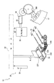
【0111】
具体的には、例えば、図13に示すように、CCD(電荷結合素子)を用いたカメラ70をカメラ支持台71に上下移動可能に取り付けておき、このカメラ70により下方の時計設置台(クレードル)72に設置された時計80を撮像し、撮像した際の画像データを図示しないコンピュータ本体に送信して画像処理プログラムによって処理し、時計80の指し示す秒、分、時や、日付を認識する。この画像認識においては、時刻表示部の明度により、指針、植字、目盛の各位置の他、これらの位置関係から文字板の方向も判別でき、また、パターン認識等によって植字や日付の文字(数字)も特定可能である。
【0112】
また、図14に示すように、時計設置台72上に時計の外形形状に応じた設置マーク73を複数施したり、図15に示すような溝状の段差部74を複数設けてもよく、こうすることにより、大きさの異なる時計を設置する場合でも、文字板の方向が常に同じになるとともに、文字板の中心が同じ位置となり、指針および日付の認識精度が向上する。その他、図16に示すように、時計80のバンド部分を両側から等しい押圧力で挟持可能な押圧機構75を設けてもよく、ボタン76の操作によって時計80の着脱を容易にできるうえ、12時・6時方向を常に合わせた状態で設置でき、やはり認識精度が向上する。
【0113】
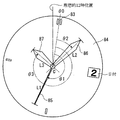
そして、このようなカメラを用いた場合、時刻を読み取るには、文字板の向きと各指針の角度を知る必要がある。どちらを知る場合でも先ず、文字板の中心を知る必要があるが、これには3針あるいは2針(秒針がない場合)の交点を見付ければよく、画像データから容易に認識できる。
次に、12時方向であるが、これは図14〜15に示した時計設置台72を用いること等により、時計が略定位置に設置されるため、理想的な12時位置に最も近い植字または目盛の中心を12時位置として決めればよい。すなわち、図17に示すように、時計設置台上での理想的12時位置に対して、実際の12時位置θ0がずれて設置された場合でも、最も近い目盛83の中心を画像処理によって認識することで、実際の12時位置θ0を確実に特定できる。
次いで、指針の種類の認識だが、図17において、3針式の場合には、文字板84の中心C(指針の交点)から指針の先端までの長さL1〜L3が長い順に秒針85、分針86、時針87と判別すればよい。以上により、12時位置θ0から秒針85までの角度θ1、分針86までの角度θ2、および時針87までの角度θ3を読み取れば、時刻を特定することができる。
【0114】
日付は、3時方向または6時方向にある文字を読めばよい。しかし、日付は他の位置に表示されることもあるため、例えば、図18に示すように、日付の印字された日車88が文字板84よりも低い(カメラ70からより遠い)位置に表示されることを利用することで、カメラで焦点位置を変えて撮像した際の焦点位置の違いにより、日付部分の表示位置を認識することができる。
【0115】
さらに、特殊デザインの表示部を有した時計などには、以上の認識アルゴリズム(画像処理プログラム)で認識できない場合があるが、この場合には、その時計専用の認識アルゴリズムを用意すればよく、時計のモデル名(いわゆるリファレンスナンバー)を入力することで認識アルゴリズムを自動的に切り換わるようにすればよい。
また、文字板の12時位置や、指針の一部、日付の表示部分等に赤外塗料などの不可視塗料を塗布してマーキングしておけば、特殊な表示部を有した時計でも外観デザインを損ねることなく、かつ認識アルゴリズムの切換も行うことなく各部の位置を確実に認識できる。
【0116】
なお、時針と分針とが重なっており、長さの短い時針の認識が困難な場合には、分針のみを認識できることをもって時針が分針と重なっていると判断してもよく、このような場合でも、図17に示す角度θ3≒θ2と判断することで、時刻を支障なく特定できる。この際、時針の位置認識に多少の誤差が生じる場合もあるが、時針が5度といった大きな指示範囲で同じ時間を示すことから、実際の位置認識には精度上問題とならない。勿論、互いに重なっていることを認識できれば、重なっている分針の位置から、時針の位置を演算によって正確に求めることも可能である。
【0117】
前記各実施形態において、日車の駆動を圧電アクチュエータを用いて行っていたが、これに限らず、ステッピングモータ等のモータを用いてもよい。
前記各実施形態において、秒,分,時を示す指針をステッピングモータにより駆動し、日付を示す日車を圧電アクチュエータにより駆動していたが、これに限らず、秒から日付までの駆動を1つのステッピングモータで駆動してもよい。
また、秒針と、時針および分針とを別々の駆動装置により、駆動する構成としてもよい。
前記各実施形態においては、日車駆動用の圧電アクチュエータは一方向のみ回転するものであったが、勿論両方向(日付を遡るようにも表示を変えられる)に回転するタイプの圧電アクチュエータでもよい。
【0118】
また、比較結果が一致するまで日車や秒針を1ステップずつ進める信号を送信していたが、これに限らず、例えば、CPU等で処理することにより、これらの信号をまとめた数ステップ分駆動させる1つの信号を送信する構成としてもよい。この場合には、時計側には、送信されたステップ数を管理するカウンタを設ける必要がある。
【0119】
また、本発明は、例えば、以下のような態様により実現することができる。
すなわち、少なくとも基準となる基準時刻データを有する時刻修正指示装置を用いて、少なくとも時刻表示用の指針を有する指針式時計の指針の指示を修正するプログラムであって、前記指針式時計の指針が指示する指示時刻データが入力される時刻入力手順と、この入力された指示時刻データ、および計時手段で計時されている基準時刻データを比較する比較手順と、この比較結果に基づく修正指示信号を前記指針式時計に対して出力する通信手順と、前記指針式時計において、前記出力された修正指示信号を受信する受信手順と、受信した修正指示信号に基づいて、前記指針の指示を基準時刻データに合わせる修正手順とをコンピュータに実行させるプログラム、とすることができる。
【0120】
また、少なくとも基準となる基準時刻データを有する時刻修正指示装置を用いて、少なくとも時刻表示用の指針を有する指針式時計の指針の指示を修正するプログラムであって、前記指針式時計の指針が指示する指示時刻データが入力される時刻入力手順と、前記指針式時計に対し前記基準時刻データおよび指示時刻データを出力する通信手順と、前記指針式時計において、前記出力された各データを受信する受信手順と、受信した前記基準時刻データ、および指示時刻データを比較する比較手順と、この比較手順での比較結果に基づいて指針の指示を基準時刻データに合わせる修正手順とをコンピュータに実行させるプログラム、とすることができる。
【0121】
以上のようなプログラムによれば、例えば、時刻修正指示装置をコンピュータにより構成することにより、時計の使用者は、通信回線等を利用してデータをダウンロードして修正作業を行うことができる。この際、時計の機種に応じたデータをダウンロードさせる構成とすることもできる。
【0122】
また、例えば、時刻修正指示装置を、指針が指示する時刻等が入力されるクライアント機としての入力端末機と、この入力端末機に接続されたサーバとを備えて構成し、比較手段や修正手段等の機能をサーバで行う構成にできる。この場合には、例えば、時計ごとに応じた修正履歴等をサーバで管理する等ができる。
その他、本発明の実施時の具体的な構造および形状等は、本発明の目的を達成できる範囲で、他の構造等としてもよい。
【0123】
【発明の効果】
本発明によれば、指針式時計と時刻修正指示装置とを通信可能な状態とし、指針式時計の指示時刻を入力するだけで、時刻修正指示装置および指針式時計において自動的に指示時刻が修正される。このため、作業者は、わざわざ、リューズやボタン等を操作することなく、簡単に時刻を修正でき、修正用の時計が沢山ある場合でも効率的に作業を行うことができるという効果がある。
また、指針式時計に、データ受信用の通信手段を設けるだけなので、液晶装置等を設ける場合に比べて、時計の大型化やコスト高を防止できるとともに、時計の外観構成等に大きな変更を加える必要もない。
【図面の簡単な説明】
【図1】本発明の日時修正システムを示す図である。
【図2】第1実施形態に係る時計の表示部分を示す図である。
【図3】第1実施形態に係る時計のムーブメントの構成を示す図である。
【図4】第1実施形態に係るムーブメントの機能を示すブロック図である。
【図5】第1実施形態に係る日時調整装置の機能を示すブロック図である。
【図6】第1実施形態に係る日時修正システムにおけるモニタの表示画面を示す図である。
【図7】第1実施形態に係る時計の日時修正手順を示すフロー図である。
【図8】第2実施形態に係る日時修正システムを構成する修正指示装置の機能を示すブロック図である。
【図9】第2実施形態に係る時計の機能を示すブロック図である。
【図10】第2実施形態に係る日時修正システムにおいて、日時修正の手順を示すフロー図である。
【図11】第2実施形態に係る日時修正システムにおいて、日時修正の手順を示すフロー図である。
【図12】本発明の変形例を示す図である。
【図13】本発明の変形例を示す斜視図である。
【図14】本発明の変形例を示す斜視図である。
【図15】本発明の変形例を示す斜視図である。
【図16】本発明の変形例を示す斜視図である。
【図17】本発明の変形例を示す平面図である。
【図18】本発明の変形例を示す断面図である。
【符号の説明】
1,2…日時修正システム(時刻修正システム)、10,50…指針式時計、16…指針、20,60…修正指示装置(時刻修正指示装置)、21…入力部(時刻入力手段)、24…時計設置台(通信手段)、33…ステッピングモータ(モータ)、35…日車駆動部(修正手段)、41…駆動制御手段、42…カウンタ(比較手段)、43…外部信号検出回路(通信手段)、44… 時刻修正制御回路(比較手段)、221…計時部(計時手段)331… モータコイル(通信手段)、511…時刻修正制御回路(修正手段)、611 制御部(比較手段)。[0001]
BACKGROUND OF THE INVENTION
The present invention relates to a time adjustment system, a time adjustment instruction device, a pointer type timepiece, and a time adjustment method.
[0002]
[Background]
2. Description of the Related Art Conventionally, there is known a pointer type timepiece with a date display that displays a time according to a position of a rotating hand and displays a date by a number on the date wheel by a rotating date wheel. In this date-type pointer-type timepiece, a primary battery such as a silver battery is provided to drive the timepiece itself. For this reason, for example, when the battery runs out and needs to be replaced, bring the watch to the watch store, and the watch store opens the back of the watch and replaces the battery. Was adjusting.
[0003]
In addition, the date-type pointer-type timepiece has a so-called auto-calendar that automatically corrects the date displayed on the date wheel, since one month in the calendar is 30 days or 31 days or a leap year exists. Those with functions have also been developed. In such watches, primary batteries are also used.If the batteries run out, replace the batteries as before, adjust the time and date, and adjust the time and date for setting the auto calendar function. I was adjusting.
Regardless of the presence or absence of these auto-calendar functions, the time, date, and year / month are generally adjusted by operating a crown or a button in such a timepiece.
[0004]
[Problems to be solved by the invention]
However, such adjustment work is troublesome because it must be carried out using a relatively small member such as a crown or a button, and the adjustment work is very complicated. For this reason, when a large number of watches requiring battery replacement are brought in, it takes a considerable amount of time to adjust the date and time associated with battery replacement and delays return to the user.
[0005]
In the watch with an auto calendar function, as described above, when the battery is replaced, the year and month must be adjusted, and the adjustment mechanism and method using the crown and buttons are complicated. For this reason, in order to solve this problem, for example, in Japanese Patent Laid-Open No. 9-61555, a liquid crystal display device or switch dedicated to date correction is provided inside the back cover of the watch, and these liquid crystal display devices and switches are used. A technique for correcting the display date of the date dial of the watch via an internal date correcting circuit or the like by inputting the correct date is disclosed.
However, in this case, since a liquid crystal display device and a switch are separately provided for correcting the date, the number of members such as a liquid crystal panel, a circuit, and a press plate is increased, leading to an increase in the cost and size of the watch. there were.
In addition, even if the counter setting with date information is reset due to some action such as static electricity, and the date is corrected for reasons other than battery replacement, it is necessary to open the back cover and correct the date. There was also a problem that was bad.
[0006]
Further, as shown in Japanese Patent Laid-Open No. 11-190781, in order to provide an auto-calendar function, a drive device for driving the hour / minute / second hand and the date wheel is often provided separately. It is necessary to provide a switch for detecting that the minute / second hand is at midnight, which is disadvantageous in terms of the size of the watch, the number of parts, and the cost of assembly work.
[0007]
Japanese Patent Application Laid-Open No. 10-62567 has a setting unit for setting an auto calendar function in the back cover of a watch, and a calendar and time as calendar information are written in the setting unit with a pencil or the like. What corrects the date and time is disclosed. However, in this case, a space for providing the setting unit is required, which hinders downsizing of the timepiece and can be considered to be small, but in this case, it is difficult to set. Produce. Furthermore, since the setting method is not always simple, there is a need to see a manual or the like, and there is a possibility that the work becomes complicated.
[0008]
On the other hand, there may be a configuration in which a specific button is separately provided on the exterior for correcting the date. Has a problem of deteriorating its appearance.
[0009]
SUMMARY OF THE INVENTION An object of the present invention is to provide a time correction system, a time correction instruction device, and a pointer that can easily correct the time without increasing the size and cost of the watch without making a change such as providing a button or the like on the exterior part. An object is to provide a timepiece and a time correction method.
[0010]
[Means for Solving the Problems]
A time adjustment system according to the present invention is a time adjustment system comprising at least a pointer-type timepiece having a time display indicator and a time adjustment instruction device having at least reference time data as a reference, the time adjustment instruction device Includes time measuring means for measuring the reference time data, time input means for inputting instruction time data indicated by the hands of the pointer-type timepiece, and outputting the reference time data and instruction time data to the pointer-type timepiece Communication means capable of receiving each data from the time correction instruction device, drive control means for controlling driving of the hands, and the received reference time data. Comparing means for comparing the instruction time data with the instruction time data, and a correction means for adjusting the instruction of the pointer to the reference time data based on the comparison result of the comparison means. Characterized in that it obtain.
[0011]
Here, as the pointer type timepiece, a timepiece having a function of displaying the date by the date wheel, a timepiece having a so-called auto calendar function, a timepiece having no date display function, or the like can be adopted. Note that the hands are hour hand, minute hand, second hand and the like, and the shape includes not only a normal needle-like shape but also a disk-like shape having a scale.
[0012]
In addition, as the time adjustment instruction device, for example, a computer (PC) that measures reference time data, a device that functions as a so-called radio timepiece that receives a radio wave including standard time information and corrects the time is adopted. it can. The reference time data can be obtained through a telephone line, receive a radio wave including the above-mentioned standard time information, or can be obtained using a service in which time information is mounted on a mobile phone radio wave. Also, a quartz clock function can be provided in the time correction instruction device, and the time of this clock function can be used as reference time data.
Furthermore, it is possible to use a method or service for adjusting the reference time of a time adjustment instruction device constituted by a computer or the like using NTP (Network Time Protocol) or the like via a communication line such as the Internet.
[0013]
Here, as a configuration for driving the pointer, for example, a predetermined motor such as a stepping motor is rotated by electric power from a primary battery or the like, and this rotational force is transmitted by a gear train or the like to drive the pointer at a constant speed. Things can be adopted.
As communication means, for example, those using electromagnetic induction, infrared communication, communication by electrical connection by USB (Universal Serial Bus), SCSI, etc., optical communication, acoustic wave (ultrasonic wave) communication and other various types It can be realized using an interface.
[0014]
In the invention as described above, for example, an operator of a watch shop can communicate between the communication means of the pointer-type timepiece and the communication means of the time adjustment instruction device after opening the back cover of the pointer-type timepiece and replacing the battery. As the state, for example, the state where the communication wiring is connected, the instruction time is input from the time input means of the time correction instruction device while looking at the pointer on the dial.
Then, in the time correction instruction device, the input instruction time data and the reference time data timed by the time measuring means are output from the communication means to the pointer type timepiece.
Next, in the pointer-type timepiece, these data are received by the communication means, the received reference time data and instruction time data are compared by the comparison means, and based on the comparison result, the indication of the pointer is given by the correction means. It is adjusted to the reference time data. As described above, the time of the pointer type clock is corrected.
[0015]
According to the present invention, the operator can communicate with the pointer-type timepiece and the time adjustment instruction device, and only inputs the instruction time of the pointer-type timepiece. The indicated time is automatically corrected. For this reason, the operator can easily correct the time without having to manually operate the crown or the button, and can efficiently perform work even when there are many correction watches.
In addition, for example, in a pointer type timepiece, a motor coil of a motor for driving a pointer is used as a communication unit, and a correction unit and a comparison unit are incorporated in the IC part of the timepiece, so that a new part compared to a general timepiece. Therefore, it is possible to suppress the increase in the number of parts and to manufacture a watch at a low cost.
Furthermore, since only communication means for data reception and comparison means are provided, it is possible to prevent an increase in the size and cost of the watch as compared with the case where a liquid crystal device or the like is provided, and it is also necessary to make a major change in the external configuration of the watch. Absent.
[0016]
In the time correction system described above, the pointer-type timepiece includes a current time counter that counts the current time, and the correction means of the pointer-type timepiece counts up in synchronization with the drive of the drive control means and the communication means Based on the comparison result of comparing the hand position counter to which the instruction time data received at the input is input, the reference time data counted by the current time counter and the instruction time data counted by the hand position counter. And a matching circuit for inputting a correction instruction signal to the drive control means.
In this case, the current time counter is provided in the pointer type timepiece, and the hand position counter and the coincidence circuit are simply provided as a software configuration in the correction means of the pointer type timepiece. Does not hinder downsizing and weight reduction.
[0017]
A time adjustment system according to the present invention is a time adjustment system comprising at least a pointer-type timepiece having a time display indicator and a time adjustment instruction device having at least reference time data as a reference, the time adjustment instruction device Includes time measuring means for measuring the reference time data, time input means for inputting instruction time data instructed by the hands of the pointer type timepiece, reference time data being timed by the time measuring means, and the time input means And a communication unit capable of outputting a correction instruction signal based on the comparison result to the pointer type timepiece, wherein the pointer type timepiece includes the time correction instruction. A communication means capable of receiving a correction instruction signal from the apparatus; a drive control means for controlling the driving of the pointer; and an instruction for the pointer based on the received correction instruction signal. Characterized in that it comprises a correction means to fit the quasi-time data.
[0018]
In the invention as described above, for example, an operator of a watch shop can communicate between the communication means of the pointer-type timepiece and the communication means of the time adjustment instruction device after opening the back cover of the pointer-type timepiece and replacing the battery. As the state, for example, the state where the communication wiring is connected, the instruction time is input from the time input means of the time correction instruction device while looking at the pointer on the dial.
Then, in the time correction instruction device, the input instruction time data and the reference time data measured by the time measuring means are compared by the comparison means, and a correction instruction signal based on the comparison result is sent from the communication means to the pointer type timepiece. Is output.
Next, in the pointer type timepiece, the correction instruction signal is received by the communication means, and the instruction of the pointer is adjusted to the reference time data by the correction means based on the received correction instruction signal. As described above, the time of the pointer type clock is corrected.
[0019]
According to the present invention, the operator can communicate with the pointer-type timepiece and the time adjustment instruction device, and only inputs the instruction time of the pointer-type timepiece. The indicated time is automatically corrected. For this reason, the operator can easily correct the time without having to manually operate the crown or the button, and can efficiently perform work even when there are many correction watches.
[0020]
In addition, since only the communication means for data reception is provided in the pointer-type timepiece, it is possible to prevent an increase in the size and cost of the timepiece compared to the case where a liquid crystal device or the like is provided, and to make a major change in the external configuration of the timepiece. There is no need.
[0021]
In this time adjustment system, the comparison means of the time adjustment instruction device stores the instruction time data input by the input means and counts the instruction time data as an initial value, and counts by the time measurement means. It is preferable to provide a coincidence circuit that compares the reference date and time data that has been set and the value counted by the hand position counter and outputs a correction instruction signal based on the comparison result.
In this case, the comparison unit of the time correction instruction device can be configured relatively simply by providing the hand position counter and the coincidence circuit as a software configuration. As described above, since the hand position counter and the coincidence circuit are provided on the time correction instruction device side, the configuration on the timepiece side can be simplified.
[0022]
In the above, it is preferable that the pointer-type timepiece includes a motor having a motor coil and driving the pointer, and the motor coil also serves as the communication unit that receives data from the outside. A stepping motor or the like can be employed as the motor.
In this case, by using the motor coil of the motor used for driving the hands and receiving data from the outside, there is no need to re-install the receiving antenna member or the like in the watch. The cost and size of the watch can be reduced.
[0023]
The pointer-type timepiece preferably includes a secondary battery for power supply for driving the drive control means. A secondary battery is a battery that stores energy generated by a generator. For example, a solar charging method or an automatic power generation method can be adopted. Further, the energy for driving the pointer-type timepiece can be stored in the secondary battery by various charging methods such as an external charging method in which electric power is guided from the time correction instruction device.
By providing such a secondary battery, the charging voltage drops, the pointer stops, and even when the battery is charged and the date and time are corrected, there is no need to open and close the back cover. Can be improved.
[0024]
In the above, it is preferable that the time correction instruction device is constituted by a computer and the time input means is constituted by a keyboard.
In this case, the time correction instruction device is configured as a computer, and at this time, the time input means is a keyboard, so that the operator who performs the correction can easily become comparatively familiar and improve the operability. Further, as compared with the case where a dedicated time adjustment instruction device is configured, the time adjustment instruction device can be configured simply by incorporating a program into the computer.
[0025]
In the above, it is preferable that the indicated time data input by the time input means is at least hour, minute, and day indicated by the hands, and in this way, a general hand-held timepiece with a date indicator is used. Can also respond.
[0026]
A pointer-type timepiece according to the present invention is a pointer-type timepiece in which an indication of the pointer is corrected by a time adjustment instruction device having at least a time display indicator and having at least reference reference time data. A communication means capable of receiving the instruction time data and the reference time data which are input to the time adjustment instruction device by a time input means and output from the time adjustment instruction device. Driving control means for controlling the driving of the hands, comparing means for comparing the received reference time data with the indicated time data, and correcting means for adjusting the indication of the hands to the reference time data based on the comparison result of the comparing means It is characterized by providing.
[0027]
According to the present invention, for example, by using a correction instruction device similar to that described above, the pointer-type timepiece and the time correction instruction device are in a communicable state, and only by inputting the indication time of the pointer-type timepiece, Since the instruction time is corrected, the time can be easily corrected without operating the crown or the button, and the work can be performed efficiently. Further, for example, by using the motor coil of the motor for driving the pointer as the communication means, and incorporating the correction means and the comparison means in the IC portion of the timepiece, it is not necessary to incorporate new parts compared to a general timepiece. The increase in the number of parts can be suppressed, and the watch can be manufactured at a low cost.
[0030]
The time correction instruction device according to the present invention has at least reference time data serving as a reference, and based on this reference time data, the time correction capable of correcting the indication of the hands of the pointer type clock having at least a time display hand An indication device, a time measuring means for measuring the reference time data, a time input means for inputting instruction time data indicated by a pointer of the pointer type timepiece, and the reference time data and instruction for the pointer type timepiece And communication means capable of outputting time data.
[0031]
According to the present invention, for example, by using a pointer-type timepiece similar to that described above, the pointer-type timepiece and the time adjustment instruction device are in a communicable state, and only by inputting the indication time of the pointer-type timepiece, Since the instruction time is corrected, the time can be easily corrected without operating the crown or the button, and the work can be performed efficiently. Further, since the correction instruction apparatus side is not provided with the comparison means, the configuration of the correction instruction apparatus can be simplified.
[0032]
A time correction instruction device according to the present invention includes at least reference time data serving as a reference, and based on the reference time data, outputs a time correction signal for a pointer-type timepiece having at least a time display pointer. An indicating device, wherein time measuring means for measuring the reference time data, time input means for inputting instruction time data indicated by the hands of the pointer-type timepiece, reference time data being timed by the time measuring means, And comparing means for comparing the instruction time data input by the time input means, and communication means capable of outputting a correction instruction signal based on the comparison result to the pointer type timepiece.
[0033]
According to the present invention, for example, by using a pointer-type timepiece similar to that described above, the operator can communicate with the pointer-type timepiece and the time adjustment instruction device, and only inputs the instruction time of the pointer-type timepiece. Since the instruction time is automatically corrected, the time can be easily corrected without operating a crown or a button, and the work can be performed efficiently even when there are many correction clocks.
Further, since the comparison means is provided on the correction instruction device side and the comparison means is not provided on the pointer-type timepiece side, the configuration of the pointer-type timepiece can be simplified, and the manufacturing cost of the timepiece can be reduced.
[0034]
A time correction method according to the present invention is a time correction method for correcting an indication of a pointer of a pointer-type timepiece having at least a pointer for time display using a time adjustment instruction device having at least reference time data as a reference. In the time correction instruction device, a time input procedure in which instruction time data instructed by the hands of the pointer-type timepiece is input, a communication procedure in which the reference time data and instruction time data are output to the pointer-type timepiece, In the pointer-type timepiece, a reception procedure for receiving the output data, a comparison procedure for comparing the received reference time data and instruction time data, and indication of the pointer based on a comparison result in the comparison procedure And a correction procedure for adjusting to the reference time data.
[0035]
According to the present invention, as described above, the indication time is automatically corrected simply by setting the indication time of the indication type timepiece to the state in which the indication type timepiece and the time adjustment indication device can communicate with each other. The time can be easily corrected without operating the buttons and buttons, and the work can be performed efficiently. Further, when battery replacement is not necessary, the time can be corrected without opening the back cover, so that work efficiency can be improved.
Further, in such a method, for example, in a pointer type timepiece, a motor coil of a motor for driving a pointer is used as communication means for data reception, and correction means and comparison means are incorporated in the IC portion of the timepiece. Since it is not necessary to incorporate new parts compared to a conventional watch, the watch can be manufactured at a low cost while suppressing an increase in the number of parts.
[0036]
A time correction method according to the present invention is a time correction method for correcting an indication of a pointer of a pointer-type timepiece having at least a pointer for time display using a time adjustment instruction device having at least reference time data as a reference. In the time correction instruction device, the time input procedure in which the instruction time data instructed by the hands of the pointer-type timepiece is input is compared with the input instruction time data and the reference time data measured by the time measuring means. Comparison procedure, a communication procedure for outputting a correction instruction signal based on the comparison result to the pointer-type timepiece, a reception procedure for receiving the output correction instruction signal in the pointer-type timepiece, and the received correction And a correction procedure for adjusting the indication of the pointer to the reference time data based on the indication signal.
[0037]
According to the present invention, as described above, the indication time is automatically corrected simply by setting the indication time of the indication type timepiece to the state in which the indication type timepiece and the time adjustment indication device can communicate with each other. The time can be easily corrected without operating the buttons and buttons, and the work can be performed efficiently.
Also, for example, by using the motor coil of the pointer driving motor as the communication means and incorporating the correction means into the IC portion of the timepiece, it is not necessary to incorporate a new part compared to a general timepiece. A watch can be manufactured at a low cost by suppressing an increase in the number of points.
[0038]
DETAILED DESCRIPTION OF THE INVENTION
[First Embodiment]
DESCRIPTION OF EXEMPLARY EMBODIMENTS Hereinafter, a first embodiment according to the invention will be described with reference to the drawings.
FIG. 1 is a diagram showing a date and time correction system which is a time correction system of the present invention.
As shown in FIG. 1, the date and
[0039]
FIG. 2 is a diagram showing a display part of the
The
[0040]
Although a part of the illustration is omitted in FIG. 2, in the
[0041]
Further, the
On the surface side of the
[0042]
FIG. 3 is a diagram showing the configuration of the movement of the
As shown in FIG. 3, the
[0043]
The stepping
[0044]
The
The
[0045]
The date
The
[0046]
As shown in FIG. 4, the
[0047]
The
The drive control means 41 controls the driving of the
[0048]
The
[0049]
The
[0050]
The
The
The
[0051]
The
[0052]
The
The
The
[0053]
The date
[0054]
The external signal detection circuit 43 receives data (instruction date / time data, reference time data, and reference date data described later) output from an external device such as the
[0055]
The time
[0056]
The
[0057]
The
The
The
The
[0058]
The
[0059]
The
Such a
In addition, the drive control means 41 and the date indicator drive
[0060]
Returning to FIG. 1, the
[0061]
FIG. 5 is a block diagram illustrating functions of the
As shown in FIGS. 1 and 5, the
[0062]
FIG. 6 is a diagram showing a screen displayed on the
[0063]
Returning to FIG. 5, the computer
[0064]
The clock setting table 24 is composed of a magnetic field generating circuit or the like with a built-in coil, and is a cradle-like function that functions as a communication means for outputting the data signal P output from the I /
[0065]
FIG. 7 is a flowchart showing a procedure for correcting the date and time of the clock in the clock store. First, the watch shop operator removes the back cover of the
[0066]
Next, when the operator places the
[0067]
Next, the
[0068]
Next, in the
[0069]
In the
[0070]
Next, in the
[0071]
In the
[0072]
Next, in the
[0073]
The
[0074]
As described above, the
[0075]
According to this embodiment, the following effects can be obtained.
(1) The operator can make the
[0076]
(2) By receiving external data using the
[0077]
(3) In the
[0078]
(4) Since the date indicated by the
[0079]
(5) Since the
[0080]
[Second Embodiment]
A second embodiment according to the present invention will be described below with reference to the drawings. In addition, the same code | symbol is attached | subjected to the same or equivalent component as the said 1st Embodiment, and description is abbreviate | omitted or simplified. The date and
[0081]
FIG. 8 is a block diagram illustrating functions of the
As shown in FIG. 8, the
[0082]
The
The computer
[0083]
The
[0084]
The hand position counter 441 stores instruction time data (hour, minute, second) and instruction date data (day) displayed by the
[0085]
The
[0086]
The I /
The clock setting table 24 is a cradle-like table that functions as a communication unit that outputs the data signal Q output from the I /
[0087]
FIG. 9 is a block diagram showing functions of the
As shown in FIG. 9, the
[0088]
The
[0089]
The time
[0090]
The time
[0091]
10 and 11 are flowcharts showing the procedure of date correction.
First, the watch store worker removes the back cover of the
[0092]
Next, when the operator installs the
[0093]
Next, the
[0094]
Next, in the
[0095]
In the
[0096]
Next, in the
[0097]
In the
[0098]
In the
[0099]
Next, in the
[0100]
In the
[0101]
Next, when the transmission of the motor fast-forward pulse output command is completed, the
On the other hand, in the
[0102]
According to the present embodiment, the following effects can be obtained in addition to substantially the same effects as (1) to (5) of the first embodiment.
(6) Since the
[0103]
(7) In the pointer-
[0104]
In addition, this invention is not limited to the said embodiment, Other structures etc. which can achieve the objective of this invention are included, The deformation | transformation etc. which are shown below are also contained in this invention.
In each of the above-described embodiments, the correction instruction device is configured by a computer. However, the present invention is not limited to this, and for example, it can be configured as a time
[0105]
The correction instruction device obtains the reference time using such a telephone line. However, the correction instruction device is not limited to this, for example, using a service in which time information is included in the radio wave of a mobile phone, A correction instruction device may be configured by providing a clock function. Moreover, you may utilize the time information service of the internet which the communication research institute provides information about Japanese standard time information.
Furthermore, although the reference time is obtained by connecting a telephone line, if the operator can directly correct the time of the correction instruction device, it is not necessary to connect the telephone line, and the calendar can be corrected.
[0106]
In each of the above embodiments, a hand-held timepiece having a date display function using a date wheel is adopted, but the present invention is not limited to this. Can be adopted. Note that a date display function that does not depend on the date wheel, for example, a clock having a pointer and a liquid crystal screen is also included in the scope of the present invention. A timepiece having no second hand is also included in the scope of the present invention. Furthermore, as a hand such as an hour hand or a minute hand, a disc-shaped one with a scale can be employed.
[0107]
In each of the above embodiments, a primary battery is used for power supply. For example, a secondary power source (secondary battery) such as a solar charging method, an automatic winding power generation method, an external charging method such as guiding power from a correction instruction device, etc. ) May be adopted. In this case, since there is no need to replace the
[0108]
For the communication between the timepiece and the correction instruction device, electromagnetic induction is adopted. However, the present invention is not limited to this, and other communication means such as optical communication and ultrasonic communication can also be adopted. In the former case, for example, if a solar type is used to secure electric power, a solar cell can be used for this optical sensor, and it is not necessary to provide a new sensor in the watch, so that downsizing and the like are not hindered. In the latter case, there is an advantage that the driving detection terminal of the piezoelectric actuator for driving the date dial can be used as a sensor. Note that sound waves other than ultrasonic waves may be used, and in this case, a timepiece with a buzzer can be configured.
In addition, the computer main body and the watch mounting base are electrically connected. For this connection, for example, an existing USB connection, a SCSI connection, or the like can be employed, and a wireless connection or other connection of infrared communication can be employed.
[0109]
In each of the above embodiments, the data signal is transmitted in one direction from the correction instruction device to the timepiece. However, the present invention is not limited to this. For example, a function for transmitting data from the timepiece to the correction instruction device may be provided. . In this case, it can be transmitted to the correction instructing device that the time adjustment of the clock has been completed, or the value of the current time counter in the clock can be directly read, so that there is an advantage that the time can be corrected more reliably. .
[0110]
In the present invention, the time and date input means is not limited to the keyboard, but may be a camera that recognizes the hour / minute hands and date indicated by the clock. For example, a camera for recognizing the pointer of a clock is provided on the clock mounting base, the clock is picked up by the camera, the time and date indicated by the clock are recognized by image recognition, and this is used as instruction time data for time correction control. By using such means, it is not necessary for the operator to input the designated time, so that the time adjustment work of the clock can be performed more easily, the work efficiency is improved, and the usability as the time adjustment system is improved. .
[0111]
Specifically, for example, as shown in FIG. 13, a
[0112]
Further, as shown in FIG. 14, a plurality of installation marks 73 corresponding to the outer shape of the watch may be provided on the
[0113]
When such a camera is used, in order to read the time, it is necessary to know the direction of the dial and the angle of each pointer. In either case, it is necessary to know the center of the dial first, but this can be easily recognized from the image data by finding the intersection of three or two hands (when there is no second hand).
Next, it is the 12 o'clock direction. This is because the timepiece is installed at a substantially fixed position by using the timepiece setting table 72 shown in FIGS. Alternatively, the center of the scale may be determined as the 12 o'clock position. That is, as shown in FIG. 17, even when the actual twelve o'clock position θ0 is deviated from the ideal twelve o'clock position on the watch setting stand, the center of the
Next, the type of the pointer is recognized. In FIG. 17, in the case of the three-needle type, the
[0114]
The date can be read by reading the characters at 3 o'clock or 6 o'clock. However, since the date may be displayed at other positions, for example, as shown in FIG. 18, the date wheel 88 on which the date is printed is displayed at a position lower than the dial 84 (further away from the camera 70). By utilizing this, the display position of the date portion can be recognized based on the difference in the focus position when the camera is picked up by changing the focus position.
[0115]
Furthermore, a watch with a specially designed display may not be recognized by the above recognition algorithm (image processing program). In this case, a recognition algorithm dedicated to the watch may be prepared. The recognition algorithm may be automatically switched by inputting the model name (so-called reference number).
In addition, if an invisible paint such as infrared paint is applied and marked at the 12 o'clock position of the dial, part of the pointer, date display part, etc., the appearance design can be made even for watches with special display parts. The position of each part can be reliably recognized without damaging and without switching the recognition algorithm.
[0116]
If the hour hand and the minute hand overlap and it is difficult to recognize the short hour hand, it may be determined that the hour hand overlaps the minute hand by being able to recognize only the minute hand. By determining that the angle θ3≈θ2 shown in FIG. 17, the time can be specified without any problem. At this time, there may be some error in the position recognition of the hour hand, but since the hour hand indicates the same time in a large indication range of 5 degrees, there is no problem in accuracy in the actual position recognition. Of course, if it can be recognized that they overlap each other, the position of the hour hand can be accurately obtained from the position of the overlapping minute hands by calculation.
[0117]
In each of the above embodiments, the date wheel is driven using a piezoelectric actuator. However, the present invention is not limited to this, and a motor such as a stepping motor may be used.
In each of the above embodiments, the pointer indicating the seconds, minutes, and hours is driven by the stepping motor, and the date indicator indicating the date is driven by the piezoelectric actuator. However, the present invention is not limited to this. You may drive with a stepping motor.
Moreover, it is good also as a structure which drives a second hand, an hour hand, and a minute hand with a separate drive device.
In each of the embodiments described above, the date dial driving piezoelectric actuator rotates only in one direction, but may of course be a piezoelectric actuator of a type rotating in both directions (the display can be changed so that the date can be traced back).
[0118]
In addition, a signal for advancing the date indicator and the second hand one step at a time until the comparison result matches is transmitted. However, the present invention is not limited to this. For example, by processing with a CPU or the like, these signals are driven for several steps. It may be configured to transmit one signal to be transmitted. In this case, it is necessary to provide a counter for managing the number of transmitted steps on the clock side.
[0119]
Moreover, this invention is realizable with the following aspects, for example.
That is, a program for correcting the indication of a pointer-type timepiece having at least a pointer for time display using a time adjustment indicating device having at least reference time data as a reference, the pointer of the pointer-type timepiece indicating A time input procedure in which the instruction time data to be input is input, a comparison procedure in which the input instruction time data and the reference time data timed by the time measuring means are compared, and a correction instruction signal based on the comparison result is used as the guideline. Based on the communication procedure output to the type timepiece, the reception procedure for receiving the output correction instruction signal in the pointer type timepiece, and the received correction instruction signal, the indication of the pointer is matched with the reference time data. A program that causes a computer to execute a correction procedure.
[0120]
Further, there is provided a program for correcting an indication of a pointer-type timepiece having at least a pointer for time display using a time adjustment indicating device having at least a reference time data as a reference, the pointer of the pointer-type timepiece indicating A time input procedure for inputting the indicated time data, a communication procedure for outputting the reference time data and the indicated time data to the pointer-type timepiece, and reception for receiving each of the output data in the pointer-type timepiece A program for causing a computer to execute a procedure, a comparison procedure for comparing the received reference time data and the instruction time data, and a correction procedure for adjusting the instruction of the pointer to the reference time data based on the comparison result in the comparison procedure; It can be.
[0121]
According to the above program, for example, by configuring the time correction instruction device with a computer, a watch user can download data using a communication line or the like and perform correction work. At this time, it is possible to download data corresponding to the model of the watch.
[0122]
Further, for example, the time correction instruction device is configured to include an input terminal as a client machine to which the time indicated by the pointer is input, and a server connected to the input terminal, and comparison means and correction means Etc. can be configured to be performed by a server. In this case, for example, a correction history or the like corresponding to each clock can be managed by the server.
In addition, the specific structure and shape at the time of carrying out the present invention may be other structures as long as the object of the present invention can be achieved.
[0123]
【The invention's effect】
According to the present invention, the indication time is automatically corrected in the time adjustment instruction device and the pointer type clock by simply setting the indication type of the pointer type clock and inputting the indication time of the pointer type clock. Is done. For this reason, the operator can easily correct the time without having to operate the crown or the button, and the work can be performed efficiently even when there are many correction watches.
In addition, since only the communication means for data reception is provided in the pointer-type timepiece, it is possible to prevent an increase in the size and cost of the timepiece compared to the case where a liquid crystal device or the like is provided, and to make a major change in the external configuration of the timepiece. There is no need.
[Brief description of the drawings]
FIG. 1 is a diagram showing a date correction system of the present invention.
FIG. 2 is a diagram showing a display part of the timepiece according to the first embodiment.
FIG. 3 is a diagram showing a configuration of a movement of the timepiece according to the first embodiment.
FIG. 4 is a block diagram showing functions of the movement according to the first embodiment.
FIG. 5 is a block diagram showing functions of the date and time adjustment apparatus according to the first embodiment.
FIG. 6 is a diagram showing a monitor display screen in the date and time correction system according to the first embodiment.
FIG. 7 is a flowchart showing a time and date correction procedure of the timepiece according to the first embodiment.
FIG. 8 is a block diagram illustrating functions of a correction instruction device that constitutes a date and time correction system according to a second embodiment.
FIG. 9 is a block diagram illustrating functions of a timepiece according to a second embodiment.
FIG. 10 is a flowchart showing a date / time correction procedure in the date / time correction system according to the second embodiment;
FIG. 11 is a flowchart showing a date / time correction procedure in the date / time correction system according to the second embodiment;
FIG. 12 is a diagram showing a modification of the present invention.
FIG. 13 is a perspective view showing a modification of the present invention.
FIG. 14 is a perspective view showing a modification of the present invention.
FIG. 15 is a perspective view showing a modification of the present invention.
FIG. 16 is a perspective view showing a modification of the present invention.
FIG. 17 is a plan view showing a modification of the present invention.
FIG. 18 is a cross-sectional view showing a modification of the present invention.
[Explanation of symbols]
DESCRIPTION OF
Claims (13)
前記時刻修正指示装置は、前記基準時刻データを計時する計時手段と、前記指針式時計の指針が指示する指示時刻データを入力する時刻入力手段と、前記指針式時計に対し前記基準時刻データおよび指示時刻データを出力可能な通信手段とを備え、
前記指針式時計は、前記時刻修正指示装置からの前記各データを受信可能な通信手段と、前記指針の駆動を制御する駆動制御手段と、受信した前記基準時刻データと指示時刻データとを比較する比較手段と、この比較手段での比較結果に基づいて指針の指示を基準時刻データに合わせる修正手段とを備えることを特徴とする時刻修正システム。A time adjustment system comprising at least a pointer-type timepiece having a time display indicator, and a time adjustment instruction device having at least reference time data as a reference,
The time correction instruction device includes a time measuring means for measuring the reference time data, a time input means for inputting instruction time data indicated by a pointer of the pointer type timepiece, and the reference time data and instruction for the pointer type timepiece. Communication means capable of outputting time data,
The pointer-type timepiece compares the communication means capable of receiving the data from the time correction instruction device, the drive control means for controlling the driving of the hands, and the received reference time data and instruction time data. A time correction system comprising: a comparison unit; and a correction unit that adjusts an instruction of a pointer to reference time data based on a comparison result of the comparison unit.
前記指針式時計は、現在時刻をカウントする現時刻カウンタを備え、
前記指針式時計の修正手段は、前記駆動制御手段の駆動に同期してカウントアップするとともに前記通信手段で受信した指示時刻データが入力される針位置カウンタと、前記現時刻カウンタでカウントされている基準時刻データと前記針位置カウンタでカウントされている指示時刻データとを比較してこの比較結果に基づく修正指示信号を前記駆動制御手段に入力する一致回路とを備えることを特徴とする時刻修正システム。The time correction system according to claim 1,
The pointer-type timepiece includes a current time counter that counts the current time,
The pointer-type timepiece correction means counts up in synchronization with the drive of the drive control means and is counted by the hand position counter to which the instruction time data received by the communication means is input and the current time counter. A time correction system comprising: a coincidence circuit that compares reference time data and instruction time data counted by the hand position counter and inputs a correction instruction signal based on the comparison result to the drive control means. .
前記時刻修正指示装置は、前記基準時刻データを計時する計時手段と、前記指針式時計の指針が指示する指示時刻データを入力する時刻入力手段と、前記計時手段で計時されている基準時刻データと前記時刻入力手段で入力された指示時刻データとを比較する比較手段と、この比較結果に基づく修正指示信号を前記指針式時計に対して出力可能な通信手段とを備え、
前記指針式時計は、前記時刻修正指示装置からの修正指示信号を受信可能な通信手段と、前記指針の駆動を制御する駆動制御手段と、受信した修正指示信号に基づいて指針の指示を基準時刻データに合わせる修正手段とを備えることを特徴とする時刻修正システム。A time adjustment system comprising at least a pointer-type timepiece having a time display indicator, and a time adjustment instruction device having at least reference time data as a reference,
The time correction instruction device includes a time measuring means for measuring the reference time data, a time input means for inputting instruction time data indicated by the hands of the pointer-type timepiece, and reference time data timed by the time measuring means; Comparing means for comparing the instruction time data input by the time input means, and a communication means capable of outputting a correction instruction signal based on the comparison result to the pointer-type timepiece,
The pointer-type timepiece includes a communication unit that can receive a correction instruction signal from the time adjustment instruction device, a drive control unit that controls driving of the pointer, and a pointer instruction based on the received correction instruction signal. A time correction system comprising correction means for adjusting to data.
前記時刻修正指示装置の比較手段は、前記入力手段で入力された指示時刻データを記憶しこの指示時刻データを初期値としてカウントアップする針位置カウンタと、前記計時手段でカウントされている基準日時データと前記針位置カウンタでカウントされている値とを比較してこの比較結果に基づく修正指示信号を出力する一致回路とを備えることを特徴とする時刻修正システム。The time correction system according to claim 3,
The comparison means of the time correction instruction device stores the instruction time data input by the input means and counts up the instruction time data as an initial value, and the reference date and time data counted by the time measuring means And a coincidence circuit that compares the value counted by the hand position counter and outputs a correction instruction signal based on the comparison result.
前記指針式時計は、モータコイルを有し前記指針を駆動するモータを備え、
前記モータコイルは、外部からのデータを受信する前記通信手段も兼ねていることを特徴とする時刻修正システム。In the time correction system in any one of Claims 1-4,
The pointer-type timepiece includes a motor having a motor coil and driving the pointer,
The time correction system, wherein the motor coil also serves as the communication means for receiving data from the outside.
前記指針式時計は、前記駆動制御手段を駆動するための電力供給用の二次電池を備えることを特徴とする時刻修正システム。In the time correction system in any one of Claims 1-5,
The timepiece system, wherein the pointer-type timepiece includes a secondary battery for power supply for driving the drive control means.
前記時刻修正指示装置は、コンピュータにより構成され、前記時刻入力手段は、キーボードにより構成されていることを特徴とする時刻修正システム。In the time correction system in any one of Claims 1-6,
The time adjustment system is constituted by a computer, and the time input means is constituted by a keyboard.
前記時刻入力手段で入力される指示時刻データは、前記指針が指示する少なくとも時、分、日であることを特徴とする時刻修正システム。In the time correction system in any one of Claims 1-7,
The time correction system characterized in that the instruction time data input by the time input means is at least hour, minute and day indicated by the pointer.
該時計の指針が指示する時刻であって時刻入力手段により前記時刻修正指示装置に入力され、かつこの時刻修正指示装置から出力される指示時刻データと前記基準時刻データとを受信可能な通信手段と、前記指針の駆動を制御する駆動制御手段と、受信した前記基準時刻データと指示時刻データとを比較する比較手段と、この比較手段での比較結果に基づいて指針の指示を基準時刻データに合わせる修正手段とを備えることを特徴とする指針式時計。A pointer-type timepiece having a pointer for displaying time at least, and an instruction of the pointer being corrected by a time correction indicating device having reference time data serving as a reference,
A communication means capable of receiving the time indicated by the hand of the timepiece and input to the time adjustment instruction device by the time input means and output from the time adjustment instruction device and the reference time data; A driving control means for controlling the driving of the hands, a comparing means for comparing the received reference time data with the indicated time data, and matching the indication of the hands with the reference time data based on the comparison result of the comparing means. A pointer-type timepiece comprising correction means.
前記基準時刻データを計時する計時手段と、前記指針式時計の指針が指示する指示時刻データが入力される時刻入力手段と、前記指針式時計に対し前記基準時刻データおよび指示時刻データを出力可能な通信手段とを備えることを特徴とする時刻修正指示装置。A time correction instruction device having at least reference time data as a reference, and based on the reference time data, it is possible to correct an indication of a pointer of a pointer-type timepiece having at least a pointer for time display,
Timekeeping means for timing the reference time data, time input means for inputting instruction time data indicated by the hands of the pointer-type timepiece, and output of the reference time data and instruction time data to the pointer-type timepiece And a time correction instruction device.
前記基準時刻データを計時する計時手段と、前記指針式時計の指針が指示する指示時刻データが入力される時刻入力手段と、前記計時手段で計時されている基準時刻データおよび前記時刻入力手段で入力された指示時刻データを比較する比較手段と、この比較結果に基づく修正指示信号を前記指針式時計に対して出力可能な通信手段とを備えることを特徴とする時刻修正指示装置。A time correction instruction device that outputs at least a reference time data serving as a reference, and outputs a correction signal for a pointer of a pointer-type timepiece having at least a pointer for time display based on the reference time data;
Timekeeping means for timing the reference time data, time input means for inputting instruction time data indicated by the hands of the pointer-type timepiece, reference time data timed by the timekeeping means, and input by the time input means A time correction instruction device comprising: a comparison means for comparing the indicated time data, and a communication means capable of outputting a correction instruction signal based on the comparison result to the pointer-type timepiece.
前記時刻修正指示装置において、前記指針式時計の指針が指示する指示時刻データが入力される時刻入力手順と、前記指針式時計に対し前記基準時刻データおよび指示時刻データを出力する通信手順と、
前記指針式時計において、前記出力された各データを受信する受信手順と、受信した前記基準時刻データ、および指示時刻データを比較する比較手順と、この比較手順での比較結果に基づいて指針の指示を基準時刻データに合わせる修正手順とを備えることを特徴とする時刻修正方法。A time correction method for correcting an indication of a pointer of a pointer-type timepiece having at least a pointer for time display using a time correction instruction device having at least reference time data as a reference,
In the time correction instruction device, a time input procedure in which instruction time data indicated by the hands of the pointer-type timepiece is input, a communication procedure for outputting the reference time data and instruction time data to the pointer-type timepiece,
In the pointer-type timepiece, a reception procedure for receiving the output data, a comparison procedure for comparing the received reference time data and instruction time data, and indication of the pointer based on a comparison result in the comparison procedure And a correction procedure for adjusting the time to the reference time data.
前記時刻修正指示装置において、前記指針式時計の指針が指示する指示時刻データが入力される時刻入力手順と、この入力された指示時刻データ、および計時手段で計時されている基準時刻データを比較する比較手順と、この比較結果に基づく修正指示信号を前記指針式時計に対して出力する通信手順と、
前記指針式時計において、前記出力された修正指示信号を受信する受信手順と、受信した修正指示信号に基づいて、前記指針の指示を基準時刻データに合わせる修正手順とを備えることを特徴とする時刻修正方法。A time correction method for correcting an indication of a pointer of a pointer-type timepiece having at least a pointer for time display using a time correction instruction device having at least reference time data as a reference,
In the time correction instruction device, the time input procedure in which the instruction time data indicated by the hands of the pointer-type timepiece is input is compared with the input instruction time data and the reference time data measured by the time measuring means. A communication procedure for outputting a comparison instruction and a correction instruction signal based on the comparison result to the pointer-type timepiece;
The time of the pointer type timepiece, comprising: a reception procedure for receiving the output correction instruction signal; and a correction procedure for aligning the indication of the pointer with reference time data based on the received correction instruction signal. How to fix.
Priority Applications (5)
| Application Number | Priority Date | Filing Date | Title |
|---|---|---|---|
| JP2003191996A JP4200835B2 (en) | 2002-07-08 | 2003-07-04 | Time correction system, time correction instruction device, pointer-type clock, and time correction method |
| US10/752,089 US7167417B2 (en) | 2003-07-04 | 2004-01-07 | Time correction system, time correction instruction device, pointer type timepiece, and time correction method |
| CNA2004800007645A CN1701283A (en) | 2003-07-04 | 2004-01-07 | Time correction system, time correction designating unit, pointer type clock, and method for correcting time |
| EP04700511A EP1553469A4 (en) | 2003-07-04 | 2004-01-07 | Time correction system, time correction designating unit, pointer type clock, and method for correcting time |
| PCT/JP2004/000043 WO2005003867A1 (en) | 2003-07-04 | 2004-01-07 | Time correction system, time correction designating unit, pointer type clock, and method for correcting time |
Applications Claiming Priority (2)
| Application Number | Priority Date | Filing Date | Title |
|---|---|---|---|
| JP2002198551 | 2002-07-08 | ||
| JP2003191996A JP4200835B2 (en) | 2002-07-08 | 2003-07-04 | Time correction system, time correction instruction device, pointer-type clock, and time correction method |
Publications (3)
| Publication Number | Publication Date |
|---|---|
| JP2004093557A JP2004093557A (en) | 2004-03-25 |
| JP2004093557A5 JP2004093557A5 (en) | 2005-10-20 |
| JP4200835B2 true JP4200835B2 (en) | 2008-12-24 |
Family
ID=32072072
Family Applications (1)
| Application Number | Title | Priority Date | Filing Date |
|---|---|---|---|
| JP2003191996A Expired - Fee Related JP4200835B2 (en) | 2002-07-08 | 2003-07-04 | Time correction system, time correction instruction device, pointer-type clock, and time correction method |
Country Status (1)
| Country | Link |
|---|---|
| JP (1) | JP4200835B2 (en) |
Cited By (2)
| Publication number | Priority date | Publication date | Assignee | Title |
|---|---|---|---|---|
| JP2016065825A (en) * | 2014-09-25 | 2016-04-28 | セイコーインスツル株式会社 | Time correction system, electronic equipment, timepiece, and program |
| US11409247B2 (en) | 2018-01-24 | 2022-08-09 | Citizen Watch Co., Ltd. | Analog electronic watch system and analog electronic watch |
Families Citing this family (22)
| Publication number | Priority date | Publication date | Assignee | Title |
|---|---|---|---|---|
| JP2006068417A (en) * | 2004-09-06 | 2006-03-16 | Topcon Corp | Optometer |
| JP4966042B2 (en) * | 2007-02-06 | 2012-07-04 | セイコーインスツル株式会社 | Analog radio clock |
| JP2009022102A (en) * | 2007-07-11 | 2009-01-29 | Ricoh Elemex Corp | Charging system |
| EP2458458B1 (en) * | 2010-11-26 | 2017-11-15 | The Swatch Group Research and Development Ltd. | Method for measuring the precision of a mechanical watch |
| JP5682857B2 (en) * | 2011-03-28 | 2015-03-11 | カシオ計算機株式会社 | Display car drive device |
| US9001625B2 (en) * | 2011-09-08 | 2015-04-07 | Timex Group Usa, Inc. | Wearable electronic device |
| CH708234B1 (en) * | 2013-06-27 | 2015-05-15 | Soprod Sa | Portable multifunction device controlled by external information. |
| CN105556875B (en) * | 2013-09-20 | 2018-01-16 | 精工电子有限公司 | The control method of electronic equipment, communication system and electronic equipment |
| JP6291782B2 (en) * | 2013-10-18 | 2018-03-14 | カシオ計算機株式会社 | Pointer position correcting method, pointer position correcting system, and pointer type display device |
| US9709962B2 (en) * | 2013-11-12 | 2017-07-18 | Seiko Instruments Inc. | Time correction system, electronic device, timepiece, and program |
| US10067480B2 (en) * | 2013-11-12 | 2018-09-04 | Seiko Instruments Inc. | Time correction system, electronic device, timepiece, and program |
| CN103644808B (en) * | 2013-11-30 | 2015-12-30 | 江苏宏丰奥凯机电有限公司 | Silicone oil damper scale detection tool |
| JP6400400B2 (en) * | 2014-09-10 | 2018-10-03 | セイコーインスツル株式会社 | Electronic device, time processing system, time processing method, and time processing program |
| JP6404046B2 (en) * | 2014-09-10 | 2018-10-10 | セイコーインスツル株式会社 | Electronic timepiece, time processing system, and time processing method |
| JP2016063363A (en) * | 2014-09-17 | 2016-04-25 | セイコーインスツル株式会社 | Communication system, electronic apparatus, and program |
| CN105446130B (en) * | 2015-12-16 | 2018-03-16 | 深圳智能表芯科技有限公司 | Automatic periodically time service method and the time dissemination system of a kind of intelligent clock and watch of pointer-type |
| JP6941218B2 (en) * | 2016-02-05 | 2021-09-29 | シチズン時計株式会社 | Electronic clocks, computers and hand movement control systems |
| EP3211491A1 (en) * | 2016-02-26 | 2017-08-30 | ETA SA Manufacture Horlogère Suisse | Method for automatically setting the time of a watch |
| CN105955011B (en) * | 2016-04-21 | 2019-12-24 | 深圳欧德蒙科技有限公司 | Intelligent timing method and device |
| JP6934800B2 (en) * | 2017-10-19 | 2021-09-15 | シチズン時計株式会社 | A system for compensating for deviations of the clock pointer from the reference position |
| EP3474086A1 (en) * | 2017-10-23 | 2019-04-24 | Harry Winston SA | Case for electromechanical watch and assembly comprising same |
| EP3839665A1 (en) * | 2019-12-18 | 2021-06-23 | ETA SA Manufacture Horlogère Suisse | Method for adjusting an electronic watch |
Family Cites Families (8)
| Publication number | Priority date | Publication date | Assignee | Title |
|---|---|---|---|---|
| JPS5268470A (en) * | 1975-12-04 | 1977-06-07 | Casio Comput Co Ltd | Watch device |
| JPS5533637A (en) * | 1978-08-31 | 1980-03-08 | Ricoh Elemex Corp | Time data feeding method to electronic watch |
| JPS56158980A (en) * | 1980-05-13 | 1981-12-08 | Seiko Instr & Electronics Ltd | Electronic wrist watch |
| JP2690108B2 (en) * | 1988-06-28 | 1997-12-10 | シチズン時計株式会社 | Clock device |
| JPH06258461A (en) * | 1993-03-03 | 1994-09-16 | Seiko Instr Inc | Analog electronic watch |
| JP2000305248A (en) * | 1999-04-23 | 2000-11-02 | Toshiba Corp | Pattern formation of photoresist |
| JP2002108634A (en) * | 2000-10-02 | 2002-04-12 | Seiko Epson Corp | Information processing method, information processor and recording medium in which information processing program is recorded |
| JP2003255069A (en) * | 2002-02-28 | 2003-09-10 | Sony Corp | Watch, placement table, and input/output apparatus |
-
2003
- 2003-07-04 JP JP2003191996A patent/JP4200835B2/en not_active Expired - Fee Related
Cited By (2)
| Publication number | Priority date | Publication date | Assignee | Title |
|---|---|---|---|---|
| JP2016065825A (en) * | 2014-09-25 | 2016-04-28 | セイコーインスツル株式会社 | Time correction system, electronic equipment, timepiece, and program |
| US11409247B2 (en) | 2018-01-24 | 2022-08-09 | Citizen Watch Co., Ltd. | Analog electronic watch system and analog electronic watch |
Also Published As
| Publication number | Publication date |
|---|---|
| JP2004093557A (en) | 2004-03-25 |
Similar Documents
| Publication | Publication Date | Title |
|---|---|---|
| JP4200835B2 (en) | Time correction system, time correction instruction device, pointer-type clock, and time correction method | |
| WO2005003867A1 (en) | Time correction system, time correction designating unit, pointer type clock, and method for correcting time | |
| JP6706657B2 (en) | Presentation case for electromechanical wrist watch and assembly having the same | |
| JP6291782B2 (en) | Pointer position correcting method, pointer position correcting system, and pointer type display device | |
| JP2007121077A (en) | Timepiece with calendar function, assembly method of timepiece with calendar function, and radio-controlled timepiece with calendar function | |
| JP2017142120A (en) | Analogue electronic watch, computer, time adjustment system and time adjustment method | |
| US20220373978A1 (en) | System for setting a watch | |
| JP2010261905A (en) | Analogue timepiece, mobile information device, and method for controlling driving of pointer | |
| CN113009815B (en) | Method for setting an electronic watch | |
| EP1480090A1 (en) | Portable information device | |
| JP6784035B2 (en) | Electronic clock | |
| JP2004004129A (en) | Electronic timepiece | |
| JP7004049B2 (en) | Electronic clock | |
| JP2014215106A (en) | Electronic clock | |
| JP7063362B2 (en) | Electronic clock | |
| JP6978922B2 (en) | Analog electronic clocks and analog electronic clock systems | |
| JP7318339B2 (en) | Portable device, information display method, program, system | |
| JP7318363B2 (en) | electronic clock | |
| JP2017191028A (en) | Electronic timepiece | |
| US20040027923A1 (en) | Analog electronic timepiece having train wheel setting lever | |
| JP4326896B2 (en) | Radio correction clock | |
| JP2003215275A (en) | Portable electronic device, reference timepiece and timepiece-function adjusting system | |
| JP2019191038A (en) | Electronic timepiece | |
| JP3636099B2 (en) | Electronic clock with alarm, its operation method, its control program | |
| JP2008241538A (en) | Electronic timepiece with antenna |
Legal Events
| Date | Code | Title | Description |
|---|---|---|---|
| A521 | Written amendment |
Free format text: JAPANESE INTERMEDIATE CODE: A523 Effective date: 20050623 |
|
| A621 | Written request for application examination |
Free format text: JAPANESE INTERMEDIATE CODE: A621 Effective date: 20050623 |
|
| RD02 | Notification of acceptance of power of attorney |
Free format text: JAPANESE INTERMEDIATE CODE: A7422 Effective date: 20070704 |
|
| RD02 | Notification of acceptance of power of attorney |
Free format text: JAPANESE INTERMEDIATE CODE: A7422 Effective date: 20070813 |
|
| A131 | Notification of reasons for refusal |
Free format text: JAPANESE INTERMEDIATE CODE: A131 Effective date: 20080722 |
|
| A521 | Written amendment |
Free format text: JAPANESE INTERMEDIATE CODE: A523 Effective date: 20080825 |
|
| TRDD | Decision of grant or rejection written | ||
| A01 | Written decision to grant a patent or to grant a registration (utility model) |
Free format text: JAPANESE INTERMEDIATE CODE: A01 Effective date: 20080916 |
|
| A01 | Written decision to grant a patent or to grant a registration (utility model) |
Free format text: JAPANESE INTERMEDIATE CODE: A01 |
|
| A61 | First payment of annual fees (during grant procedure) |
Free format text: JAPANESE INTERMEDIATE CODE: A61 Effective date: 20080929 |
|
| R150 | Certificate of patent or registration of utility model |
Free format text: JAPANESE INTERMEDIATE CODE: R150 |
|
| FPAY | Renewal fee payment (event date is renewal date of database) |
Free format text: PAYMENT UNTIL: 20111017 Year of fee payment: 3 |
|
| FPAY | Renewal fee payment (event date is renewal date of database) |
Free format text: PAYMENT UNTIL: 20121017 Year of fee payment: 4 |
|
| FPAY | Renewal fee payment (event date is renewal date of database) |
Free format text: PAYMENT UNTIL: 20121017 Year of fee payment: 4 |
|
| FPAY | Renewal fee payment (event date is renewal date of database) |
Free format text: PAYMENT UNTIL: 20131017 Year of fee payment: 5 |
|
| LAPS | Cancellation because of no payment of annual fees |