JP4198206B2 - Video information compression method and apparatus using motion dependent prediction - Google Patents
Video information compression method and apparatus using motion dependent prediction Download PDFInfo
- Publication number
- JP4198206B2 JP4198206B2 JP22358496A JP22358496A JP4198206B2 JP 4198206 B2 JP4198206 B2 JP 4198206B2 JP 22358496 A JP22358496 A JP 22358496A JP 22358496 A JP22358496 A JP 22358496A JP 4198206 B2 JP4198206 B2 JP 4198206B2
- Authority
- JP
- Japan
- Prior art keywords
- motion vector
- macroblock
- block
- field
- prediction
- Prior art date
- Legal status (The legal status is an assumption and is not a legal conclusion. Google has not performed a legal analysis and makes no representation as to the accuracy of the status listed.)
- Expired - Fee Related
Links
Images


Classifications
-
- H—ELECTRICITY
- H04—ELECTRIC COMMUNICATION TECHNIQUE
- H04N—PICTORIAL COMMUNICATION, e.g. TELEVISION
- H04N19/00—Methods or arrangements for coding, decoding, compressing or decompressing digital video signals
- H04N19/50—Methods or arrangements for coding, decoding, compressing or decompressing digital video signals using predictive coding
- H04N19/503—Methods or arrangements for coding, decoding, compressing or decompressing digital video signals using predictive coding involving temporal prediction
- H04N19/51—Motion estimation or motion compensation
-
- H—ELECTRICITY
- H04—ELECTRIC COMMUNICATION TECHNIQUE
- H04N—PICTORIAL COMMUNICATION, e.g. TELEVISION
- H04N19/00—Methods or arrangements for coding, decoding, compressing or decompressing digital video signals
- H04N19/10—Methods or arrangements for coding, decoding, compressing or decompressing digital video signals using adaptive coding
- H04N19/102—Methods or arrangements for coding, decoding, compressing or decompressing digital video signals using adaptive coding characterised by the element, parameter or selection affected or controlled by the adaptive coding
- H04N19/103—Selection of coding mode or of prediction mode
- H04N19/105—Selection of the reference unit for prediction within a chosen coding or prediction mode, e.g. adaptive choice of position and number of pixels used for prediction
-
- H—ELECTRICITY
- H04—ELECTRIC COMMUNICATION TECHNIQUE
- H04N—PICTORIAL COMMUNICATION, e.g. TELEVISION
- H04N19/00—Methods or arrangements for coding, decoding, compressing or decompressing digital video signals
- H04N19/10—Methods or arrangements for coding, decoding, compressing or decompressing digital video signals using adaptive coding
- H04N19/102—Methods or arrangements for coding, decoding, compressing or decompressing digital video signals using adaptive coding characterised by the element, parameter or selection affected or controlled by the adaptive coding
- H04N19/103—Selection of coding mode or of prediction mode
- H04N19/112—Selection of coding mode or of prediction mode according to a given display mode, e.g. for interlaced or progressive display mode
-
- H—ELECTRICITY
- H04—ELECTRIC COMMUNICATION TECHNIQUE
- H04N—PICTORIAL COMMUNICATION, e.g. TELEVISION
- H04N19/00—Methods or arrangements for coding, decoding, compressing or decompressing digital video signals
- H04N19/10—Methods or arrangements for coding, decoding, compressing or decompressing digital video signals using adaptive coding
- H04N19/134—Methods or arrangements for coding, decoding, compressing or decompressing digital video signals using adaptive coding characterised by the element, parameter or criterion affecting or controlling the adaptive coding
- H04N19/136—Incoming video signal characteristics or properties
- H04N19/137—Motion inside a coding unit, e.g. average field, frame or block difference
-
- H—ELECTRICITY
- H04—ELECTRIC COMMUNICATION TECHNIQUE
- H04N—PICTORIAL COMMUNICATION, e.g. TELEVISION
- H04N19/00—Methods or arrangements for coding, decoding, compressing or decompressing digital video signals
- H04N19/50—Methods or arrangements for coding, decoding, compressing or decompressing digital video signals using predictive coding
- H04N19/503—Methods or arrangements for coding, decoding, compressing or decompressing digital video signals using predictive coding involving temporal prediction
- H04N19/51—Motion estimation or motion compensation
- H04N19/56—Motion estimation with initialisation of the vector search, e.g. estimating a good candidate to initiate a search
Description
【0001】
【発明の属する技術分野】
本発明はディジタル画像信号処理の分野に関し、より具体的には複数の動き依存予測(motion dependent prediction) からビデオ情報を圧縮する方法および装置に関する。
【0002】
なお、本明細書の記述は本件出願の優先権の基礎たる米国特許出願第08/519,438号(1995年8月25日出願)の明細書の記載に基づくものであって、当該米国特許出願の番号を参照することによって当該米国特許出願の明細書の記載内容が本明細書の一部分を構成するものとする。
【0003】
【従来の技術】
ビデオ情報伝送システムは伝送されるビデオ・データ量を削減するためにビデオ圧縮を使用している。これにより、利用する伝送バンド幅の低減、伝送時間の短縮、および記憶容量の節減が可能になっている。テレビジョン信号に含まれているような、ビデオ情報を圧縮するために一般に使用されている手法では、ピクチャ・シーケンスの連続するピクチャに出現する冗長時間的ピクチャ情報(redundant temporal picture information)を低減している。冗長時間的ピクチャ情報とは、スタチック(静的)ピクチャ・セグメントと関連がある情報、つまり、連続するピクチャ間で変位を受けるだけのピクチャ・セグメントと関連がある情報のことである。これらのピクチャ・セグメントは、冗長時間的ピクチャ情報の多くが伝送ビデオ・データから除去されるような形で識別され、符号化(コード化)されている。伝送ビデオ・データは、他の伝送ピクチャからピクチャを再構築し、符号化されたピクチャ・セグメントを受信装置で挿入することを可能にするように、適当な方法で符号化されている。この時間的情報圧縮手法によれば、あるピクチャの構成ブロックが他の先行または後続ピクチャに対してどれだけの動き(モーション)があったかの推定(estimate)を行う必要がある。この動き推定(motion estimate) は動きベクトル(motion vector) と呼ばれ、ピクチャが過去または将来のピクチャから予測できるようにビデオ・データを符号化するために使用されている。このプロセスは動き補償予測(motion compensated prediction) と呼ばれ、広く知られている。
【0004】
動き補償予測を使用するビデオ圧縮標準の1つとして、MPEG(Moving Pictures Expert Group:動画像圧縮方式の標準化作業グループ)画像符号化標準(ISO/IEC 13818-2, 1994年5月10日)が広く利用されている。このフォーマットで符号化されたビデオ・データは、符号化データの連続するピクチャ、つまり、フレームの巡回シーケンス(cyclic sequence) からなっている。ある種のピクチャ(Iピクチャ)はフレーム内符号化(intra-coded) されている。すなわち、そのピクチャ自身の内部の情報からのみ符号化されている。他のピクチャ(Pピクチャ)は順方向予測で符号化されている。すなわち、過去のIピクチャまたはPピクチャからの動き補償予測を使用して符号化されている。残りのピクチャ(Bピクチャ)は順方向予測と逆方向予測の両方で符号化されている。すなわち、過去または将来のIピクチャまたはPピクチャからの動き補償予測を使用して符号化されている。従って、PピクチャとBピクチャは予測符号化されるので、PまたはBピクチャから画像再現を行うには、先行の復号化(decoded) IまたはPピクチャから導き出された情報が必要になる。これに対して、Iピクチャは予測符号化されないので、画像は単一のIピクチャ、つまり、フレームから再現することが可能である。
【0005】
【発明が解決しようとする課題】
圧縮され、予測符号化されたMPEG PピクチャとBピクチャを形成するためには、多数の動きベクトルを計算しなければならない。このことが問題となっているのは、動きベクトル計算が時間を消費する、計算集中型タスクであるためである。その結果として、伝送する圧縮ビデオ・データを得るために必要な動きベクトル計算を実行するには、高価で、複雑なハードウェアが必要になる。
【0006】
【課題を解決するための手段】
本発明の原理に従う、開示されたビデオ信号圧縮システムによれば、動きベクトルに基づく予測は、低減化された動きベクトル計算回数を使用して行われる。また、開示されたビデオ信号圧縮システムによれば、1つまたは2つ以上の動きベクトルが計算され、必要とされる動きベクトル値の残余はこれらの初期計算値から外挿(extraporate) される。外挿された動きベクトルは初期計算動きベクトル値を時間的にスケーリングすることにより計算される。
【0007】
画像を表すMPEG準拠のビデオ入力データは入力ピクセル・ブロックに変換される。最良予測ブロックおよび関連の動きベクトルは画像のあらかじめ決めたエリアに置かれている入力ピクセル・ブロックに対して決定(判断)される。さらに、候補予測ブロックは他の入力ピクセル・ブロックに対して決定(判断)される。これは、以前に決定(判断)された関連動きベクトルから動きベクトルを外挿し、外挿された動きベクトルを使用して候補予測ブロックを識別することにより行われる。候補予測ブロックは相互に比較され、これらのブロックのうち、圧縮データレート要件に一致するものが選択される。選択されたブロックは圧縮されて、出力ブロックが得られ、この出力ブロックはデータパケットにフォーマッティングされて圧縮ビデオ出力データが得られる。
【0008】
本発明の特徴によれば、候補MPEGフィールド予測ブロックは、ブロック一致サーチ(block match search)を使用して候補フィールド予測ブロックおよび関連の動きベクトルを識別することによって決定(判断)される。他の動きベクトルは関連の動きベクトルから外挿され、他の候補フィールド予測ブロックを識別するために使用される。
【0009】
本発明の別の特徴によれば、圧縮されたビデオ出力ブロックを動きベクトル外挿法を使用して出力端子から得るための装置が開示されている。
【0010】
【発明の実施の形態】
MPEG標準によれば、PピクチャとBピクチャを異なる方法で予測符号化することが可能になっている。これらの方法の各々によれば、動きベクトルの計算が必要である。予測符号化されるピクチャ(動画などの画像)はいくつかのブロック(現ブロック(Current blocks))に分割され、これらのブロックは、計算された動きベクトルを使用してブロック単位(block by block basis)で予測されている。MPEG標準では、これらのブロックはマクロブロック(macroblocks) と名づけられ、そのサイズは16×16画素(ピクセル)と規定されている。いくつかの候補予測マクロブロック(candidate predicted macroblock)は、例えば、フレーム・ベース、フィールド・ベースおよび「デュアルプライム(dual prime)」の符号化を使用して、現在予測しようとしている各マクロブロックごとに作ることが可能になっている。特定の現マクロブロック(CM)の最良予測はこれらの候補予測マクロブロックから選択されて、圧縮され伝送されるようになっている。
【0011】
MPEG標準のセクション7.6.3.3および表7−9,表7−10には、候補Pピクチャ・マクロブロック予測を作るために計算できる5個の異なる動きベクトルが定義されており、候補Bピクチャ・マクロブロック予測の場合は、10個の異なる動きベクトルが定義されている(MPEG画像符号化標準、ISO/IEC 13818-2 、1994年5月10日)。Bピクチャ予測では、5個のPピクチャ予測動きベクトルは順方向予測だけではなく、逆方向予測にも適用されている。本発明の原理は、以下で説明するように、10個のBピクチャ動きベクトルに適用可能であるが、説明を簡単にするために、以下ではPピクチャ予測だけについて説明する。
【0012】
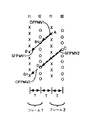
5個のPピクチャ動きベクトルは以下に示すとおりである。フィールド動きベクトルMV2〜MV5のフィールド関係図は図1に示されている。動きベクトルMV2とMV3は異なるピクチャ・フレームの同一フィールド間のベクトルであるので、同一フィールド・パリティ(Same Field Parity - SFP)をもち、各ベクトルは同一フィールド・パリティ動きベクトル (Same Field Parity Motion Vector - SFPMV)と名づけられている。動きベクトルMV4とMV5は図1に示すように、異なるピクチャ・フレームの異なるフィールド間のベクトルであるので、オポジット・フィールド・パリティ (Opposite Field Parity - OFP)をもち、各ベクトルはオポジット・フィールド・パリティ動きベクトル (Opposite Field Parity Motion Vector - OFPMV)と名づけられている。
【0013】
MV1 − 現在符号化しようとしているピクチャからストア・ピクチャ(stored picture)までのフレーム動きベクトル。
【0014】
MV2 − 現在符号化しようとしているピクチャのフィールド1(f1)からストア・ピクチャのフィールド1(f1)までの動きベクトル(SFPMV)。
【0015】
MV3 − 現在符号化しようとしているピクチャのフィールド2(f2)からストア・ピクチャのフィールド2(f2)までの動きベクトル(SFPMV)。
【0016】
MV4 − 現在符号化しようとしているピクチャのフィールド2(f2)からストア・ピクチャのフィールド1(f1)までの動きベクトル(OFPMV)。
【0017】
MV5 − 現在符号化しようとしているピクチャのフィールド1(f1)からストア・ピクチャのフィールド2(f2)までの動きベクトル(OFPMV)。
【0018】
図5と図6は、フレームの各現マクロブロックごとに最良予測マクロブロックを得るための、本発明による方法を示している。この方法によれば、低減化された計算回数を使用して必要とする動きベクトルが得られるので、単純化され、低コスト化されたハードウェアを実現して使用することが可能である。この結果得られる利点は、例えば、ビデオ・カメラのように、コストとサイズに制約があるビデオ符号化の応用分野において特に価値がある。具体的には、図5と図6の方法によれば、候補予測マクロブロックを識別して、その関連MV1〜MV5動きベクトルと平均二乗誤差(Mean Squared Error - MSE)値を求めるときの計算回数が低減化されている。候補予測ブロックのMSE値とは、候補予測ブロックのピクセル値と、それが予想する現マクロブロックの対応するピクセル値との間の、計算で求めた平均二乗誤差である。図5と図6の方法はMPEG符号化システムと関連づけて説明されているが、本発明の原理は他のビデオ圧縮システムにも応用可能である。
【0019】
概要を説明すると、ステップ10でスタートしたあとに続いて、図5のステップ15において、最良予測ブロックおよび関連の動きベクトルMV1〜MV5は上縁と左縁の画像マクロブロックについて判断される。次に、ステップ23〜70において、2つの最良フィールド予測ブロックおよび関連のフィールド動きベクトルは、符号化しようとしているフレームのフィールド1とフィールド2の残余の現マクロブロックについて判断される。これは本発明による方法を使用して、低減化された計算回数で行われる。ステップ80において、フレーム予測マクロブロックおよび関連のフレーム動きベクトルMV1も、残余の画像現マクロブロックについて判断される。これは本発明による方法を使用して、低減化された計算回数で行われる。最後に、ステップ85において、フレームおよびフィールド予測マクロブロックが相互に比較され、残余の画像マクロブロックの各々について、伝送システムのデータレート制約条件に一致する最良予測ブロックがMSEに基づいて選択される。選択された最良予測マクロブロックは、それがフィールド予測マクロブロックである場合も、フレーム予測マクロブロックである場合も、最終的に圧縮されて、伝送されるマクロブロックである。
【0020】
図5と図6を詳しく検討すると、予測しようとしているフレームの現マクロブロックは、ステップ10でスタートしたあとに続いて、図5のステップ15で入力される。ステップ15において、最良予測マクロブロックは、フレームのあらかじめ決めた「基準エリア(reference area)」に置かれた各現マクロブロックについて判断される。好適実施例では、図2に示すように、フレームの上縁と左縁からなる、基準エリアに置かれた現マクロブロックが判断される。各最良予測マクロブロックは完全「ブロック一致サーチ」を実行することにより得られる。この種の完全「ブロック一致サーチ」は、現マクロブロックに「最良一致(best match)」しているサーチ・マクロブロックを、ストア画像の中から識別する方法として公知である。この「最良一致」サーチ・マクロブロックは、対応する現マクロブロックの予測マクロブロックとして選択される。
【0021】
ブロック一致サーチを行うとき、現マクロブロックは予測画像のある領域に置かれたすべてのサーチ・マクロブロックと比較される。マクロブロックは、各サーチ・マクロブロックと現マクロブロックとの間のMSEを、2マクロブロック間の相関(correlation) を示すものとして計算することにより比較される。最低MSE値をもつ「最良一致ブロック(best match block)」が予測マクロブロックとして選択される。MSEに代わる方法として、平均絶対誤差 (Mean Absolute Error - MAE)などの他の比較基準をブロック一致サーチまたは他のタイプの選択プロセスで使用して、相関を示すことも可能である。
【0022】
ステップ15において、上縁と左縁の現マクロブロックの動きベクトルMV1〜MV5は、ブロック一致サーチ・プロセスを使用して判断される。各現マクロブロックの動きベクトルは、サーチ・プロセスで明らかにされた、現マクロブロックおよび対応する予測マクロブロックとの間のベクトル移動量(vector displacement) によって求められる。ここで説明しているブロック一致サーチ・プロセスは公知であるが、例えば、SGS-Thomson STI3220 デバイスのような、市販されている動き予測集積回路を使用して実現することが可能である。
【0023】
次に、残余の画像現マクロブロックの各々の最良予測マクロブロックおよび関連の動きベクトルが判断される。ステップ15では、現マクロブロックは、予測しようとしているフレーム1のフィールド1の上左から下右へ進んで行き、そのフレームのフィールド2がそのあとに続くように、順番にスキャンされるようになっている。このようにすると、現マクロブロックの上側ブロック(TB)とその左側ブロック(LB)の最良予測がすでに判断されていることが保証される。現マクロブロックは上記要件を満たす順序になっていれば、どのような順序でスキャンすることも可能である。
【0024】
本発明による低減化された計算回数を使用して行われるフィールド予測マクロブロックの判断はステップ20から開始される。ステップ20では、ブロック一致サーチが実行され、動きベクトルMV2〜MV5がステップ23から70までの該当フローチャート経路を実行することによって計算される。該当フローチャート経路がそのあとに続くステップ23の実行は、最初に現マクロブロックのフィールド1について行われ、次にフィールド2について行われる。
【0025】
図5のステップ23において、現フィールド (Current Field - CF)における現マクロブロックのLBとTBの最良予測マクロブロックの動きベクトル・フィールド・パリティが検査される。例えば、TBとTBの最良予測マクロブロックが共に、それぞれのピクチャのフィールド1(f1)またはフィールド2(f2)内にあれば、TBは、同一フィールド・パリティ動きベクトル (Same Field Parity Motion Vector - SFPMV)をもつ同一フィールド・パリティ(SFP)マクロブロックである。同様に、LBとLBの最良予測マクロブロックがそれぞれのピクチャの異なるフィールド内にあれば、LBはオポジット・フィールド・パリティ動きベクトル (Opposite Field Parity Motion Vector - OFPMV)をもつオポジット・フィールド・パリティ(OFP)になっている。図3は、TBとLBが共にSFPであるときの条件、つまり、共に現マクロブロックと同じフィールド・パリティをもっているときの条件を示す図である。図4は、TBがSFPマクロブロックであり、LBがOFPマクロブロックであるときの条件、つまり、TBとLBが混合フィールド・パリティであり、混合フィールド・パリティ動きベクトル(Mixed Field Parity Motion Vector - MFPMV)をもっているときの条件を示す図である。従って、ステップ23でのTBとLBのパリティ判断に応じて、TBとLBは共に同一フィールド・パリティ動きベクトル(SFPMV)をもつか、共にオポジット・フィールド・パリティ動きベクトル(OFPMV)をもつか、あるいは混合フィールド・パリティ動きベクトル(MFPMV)をもつか、のいずれかである。TBとLBがSFPMVタイプであれば、ステップ25,30,32,35および37が実行される。同様に、TBとLBがOFPMVタイプであれば、ステップ45,50,52,55および57が実行される。TBとLBがMFPMVタイプであれば、ステップ65と70が実行される。ステップ70では、最低MSE値をもつTBとLBマクロブロックの動きベクトル・フィールド・パリティに応じて、SFPMV(ステップ25〜37)経路またはOFPMV(ステップ45〜57)経路のプロセスが実行される。
【0026】
図5と図6のフローチャートは、ステップ23のあとに続くステップ25〜70が3つの経路に分割されている。最初の経路(ステップ25〜37)はTBとLB最良予測マクロブロックが共にSFPMVタイプである場合に実行される。そのあと、ステップ25の条件が満たされると、フローチャートの実行はステップ30から続行される。ステップ30において、前述したように、公知のブロック一致サーチが実行され、現フィールド内の現マクロブロックの、ストア画像内の最良一致マクロブロックが平均二乗誤差(MSE)に基づいて識別される。このサーチは、予測しようとしているフレーム内の現マクロブロック・フィールドのそれと同じである、ストア画像の相対フィールド(f1またはf2)で行われる。そのあと、同一フィールド・パリティ動きベクトル(SFPMV)は、現マクロブロックと、ストア画像内の最良一致マクロブロックとの間のベクトル移動量から計算される。
【0027】
スケール係数(scale factor)Kは、ステップ35で実行される動きベクトルの予測を最適化するようにステップ32で選択される。ステップ32において、スケール係数Kはステップ30の計算された同一フィールド・パリティ動きベクトル(SFPMV)を線形的にスケーリングして、オポジット・フィールド・パリティ動きベクトル(OFPMV)の推定値が得られるように選択される。SFPMVは、SFPVMに関連する現マクロブロックから予測マクロブロックまでの経過時間と、推定されたOFPMVに関連する現マクロブロックから予測マクロブロックまでの経過時間の差に基づいて線形的にスケーリングされる。例えば、図7は、2つのケースにおいてOFPMVを予測するときのK値がどのように求められるかを示している。ケース1では、マクロブロック中心点A(フレーム2、フィールド1)とB(フレーム1、フィールド1)間の計算されたSFPMV1については、K値は.5と計算され、マクロブロック中心点AとB1(フレーム1、フィールド2)間のOFPMV1 は.5*SFPMV1と推定される。これは、1次数の近似値になるように、AからB1までの時間(T)がAからBまでの時間(2T)の.5であるためである。同様に、ケース2では、マクロブロック中心点C(フレーム2、フィールド2)とD(フレーム1、フィールド2)の間のSFPMV2については、K値は1.5と計算され、マクロブロック中心点CとD1(フレーム2、フィールド2)の間のOFPMV2は1.5*SFPMV2と推定される。これは、1次数の近似値になるように、CからD1までの時間(3T)がCからDまでの時間(2T)の1.5であるためである。Tは、これらの例における連続フィールド間の時間期間である。類似の時間的スケーリング動きベクトル推定は「デュアルプライム(Dual prime)」タイプの予測で適用されている(セクション7.6.3.6 MPEG画像符号化標準、ISO/IEC 13818-2 、1994年5月10日)。
【0028】
好適実施例では、1次数の線形スケーリングが採用されているが、別のスケーリング手法を採用することも可能である。前述したスケーリング手法は非連続画像間、つまり、例えば、可変時間期間が分離している画像間の動きベクトル推定を包含するように容易に拡張することが可能である。また、スケーリングは、MPEG「デュアルプライム」タイプの予測で使用されているような、異なるパリティのフィールド・ライン間の垂直シフトを補償することも可能である。本発明は、2つのインタレース・フィールド(interlaced field)からなる画像と関連づけて説明されているが、本発明の原理と動きベクトル推定プロセスは、ノンインタレース(順次走査型(progressive-scan type) )ピクチャ・シーケンスからなる画像シーケンスに適用することも可能である。このようなシーケンスでは、シーケンス内の各ピクチャはフレームと考えることができる。
【0029】
ステップ35(図5と図6)において、ステップ32で求めたK値にステップ30で求めたSFPMVをかけて、上記のケース1と2に例示するように推定OFPMVが得られる。フィールド予測マクロブロックはストア画像の中で、この初期推定OFPMVを使用して識別される。この初期推定OFPMVは、識別されたマクロブロック中心を取り巻く領域において(OFPMV)動きベクトルを乱すこと(perturbing)によってさらに最適化されて、追加のローカル(局所)予測マクロブロックが求められる。最良フィールド予測マクロブロックと最適推定OFPMVは、これらのローカル予測ブロックの関連MSE値を計算すると、識別することができる。最低MSE値をもつローカル・マクロブロックは最適ローカル・マクロブロックとして選択され、その関連OFPMVは最適OFPMV値として選択される。
【0030】
図8は、関連の初期識別マクロブロックの中心ピクセル(W)を取り巻く初期推定OFPMVの乱れ(perturbation)を示す図である。乱れたOFPMVのサーチは中心点が‘Z’で示された8ピクセルをもつ8マクロブロックについて行われる。Wを取り巻くサーチ領域は、システムの計算制約条件に合わせて必要に応じて拡大することも、縮小することも可能である。乱れサーチを行うかどうかの判断は、例えば、OFPMV MSE値の大きさといった、推定品質基準に基づいて行うことができる。乱れサーチ領域のサイズは、上記品質基準に応じて同じように変えることが可能である。現フィールド内の現マクロブロックの最良予測マクロブロックは、フローチャート(図6)のステップ37で最低MSE値をもつSFPMVまたはOFPMV識別マクロブロックとして選択される。
【0031】
ステップ23のあとに続く、図5〜図6のフローチャートの第2経路(ステップ45〜57からなる)は、TBとLB最良予測マクロブロックが共にOFPMVタイプであるときに実行される。ステップ45の条件が満たされていれば、ステップ50〜57が実行される。ステップ45〜57は、ステップ50でOFPMVが計算されることを除けば、ステップ25〜37と同じである。これは、ブロック一致サーチを実行して現マクロブロックが置かれているフィールドと反対側の、ストア画像のフィールド内の最良一致マクロブロックを識別することにより行われる。次に、スケール係数Kがステップ52で求められ、ステップ55で行われる、OFPMVからのSFPMVの推定を最適化する。スケール係数Kは、OFPMVとSPFMV現マクロブロックと予測マクロブロック間の経過時間の差に基づいて、ステップ32で説明した線形スケーリング手法によって求められる。ステップ55において、ストア画像内の最適化フィールド予測マクロブロックおよび関連の最適化SFPMV予測とMSE値は、ステップ35に関連して説明した乱れサーチ手法を使用して判断される。ステップ57では、現フィールド内の現マクロブロックの最良予測マクロブロックは、最低MSE値をもつSFPMVまたはOFPMV識別マクロブロックとして選択される。
【0032】
ステップ23のあとに続く、図5〜図6のフローチャートの第3経路(ステップ65と70からなる)は、TBとLB最良予測マクロブロックがMFPMVタイプであるときに実行される。ステップ65の条件が満たされていれば、ステップ70が実行される。ステップ70において、TBとLB最良予測マクロブロックのMSE値が比較される。最低MSE値をもつTBまたはLB最良予測マクロブロックのフィールド・パリティ・タイプ(SFPMVまたはOFPMV)が判断される。最低MSE値をもつTBまたはLBマクロブロックがSFPMVタイプであれば、SFPMV経路(ステップ30〜37)が実行される。最低MSE値をもつTBまたはLBマクロブロックがOFPMVタイプであれば、OFPMV経路(ステップ50〜57)が実行される。例えば、TBとLB最良予測ブロックのMSE値を比較したとき、LB予測マクロブロックが最低MSE値をもっていて、OFPMVタイプであれば、OFPMV経路が実行される。
【0033】
ステップ23〜70で詳しく説明したフィールド予測プロセスは、現在予測しようとしているフレームの次のフィールドについて繰り返される。このようにして、最良予測マクロブロックおよび関連の動きベクトルは、予測しようとしているフレームのフィールド1とフィールド2の両方の各マクロブロックについて得られることになる。
【0034】
ステップ80において、フレーム予測マクロブロックおよび関連フレーム動きベクトルMV1が残りの現マクロブロックについて判断される。これは、図9のフローチャートに詳しく説明されている方法を使用して、本発明による低減化された計算回数で行われる。
【0035】
ステップ100でのスタートのあとに続く図9のステップ105において、現在符号化しようとしているフレームのフィールド1のSFPMV(SFPMV−f1)(これはステップ37または57で判断されたもの)がフレーム予測のために使用される。ステップ105において、このSFPMV−f1動きベクトルはフレーム動きベクトルMV1として使用され、予測しようとしている現マクロブロックのフレーム予測マクロブロックがストア画像の中から識別される。ステップ110において、ベクトルSFPMV−f1で識別されたフレーム予測マクロブロックを取り巻くストア画像のフィールド1でローカル・サーチが行われる。これが行われるのは、初期SFPMV−f1予測を最適化するためである。このローカル・サーチは、ステップ35と55(図5)の乱れサーチに関して上述したのと同じ方法で行われる。つまり、SFPMV−f1識別マクロブロックの中心ピクセルを取り巻く中央ピクセルをもつ8マクロブロックのMSE値が計算される(図9のステップ110)。ステップ 115において、8マクロブロックのMSE値が比較され、最低MSE値をもつマクロブロックが第1フレーム予測マクロブロックとして選択される。同様に、ステップ120において、ストア画像のフィールド2内のSFPMV−f1識別マクロブロックの中心ピクセルを取り巻く中央ピクセルをもつ8マクロブロックのMSE値が計算される。ステップ125において、これらの8マクロブロックのMSE値が比較され、最低MSE値をもつマクロブロックが第2フレーム予測マクロブロックとして選択される。最低MSE値をもつ第1または第2フレーム予測マクロブロックはフレーム予測マクロブロック(MV1−f1)として選択され、その関連動きベクトルはMV1−f1動きベクトルとして選択される(ステップ125)。
【0036】
ステップ105〜125は基本的にステップ130〜150で繰り返されて、フィールド2のフレーム予測マクロブロック(MV1−f2)および関連の動きベクトル(MV1−f2)が判断される。ステップ130において、以前に判断された(図6のステップ37または57で)SFPMV−f2動きベクトルはフレーム動きベクトルMV1として使用され、予測しようとしている現マクロブロックのフレーム予測マクロブロックがストア画像の中から識別される。ステップ135において、ベクトルSFPMV−f2で識別されたフレーム予測マクロブロックを取り巻くストア画像のフィールド1でローカル・サーチが行われる。SFPMV−f2識別マクロブロックの中心ピクセルを取り巻く中央ピクセルをもつ8マクロブロックのMSE値がステップ135において計算される。ステップ140において、これらの8マクロブロックのMSE値が比較されて、最低MSE値をもつマクロブロックが第3フレーム予測マクロブロックとして選択される。ストア画像のフィールド2内のSFPMV−f2識別マクロブロックの中心ピクセルを取り巻く中央ピクセルをもつ8マクロブロックのMSE値も、同じようにステップ145で計算される。ステップ150において、これらの8マクロブロックのMSE値が比較され、最低MSE値をもつマクロブロックが第4フレーム予測マクロブロックとして選択される。さらに、最低MSE値をもつ第3または第4フレーム予測マクロブロックはフレーム予測マクロブロック(MV1−f2)として選択され、その関連動きベクトルはMV1−f2動きベクトルとして選択される(ステップ150)。次に、ステップ155において、フィールド1とフィールド2を結合した最低MSE値をもつMV1−f1またはMV1−f2マクロブロックのどちらかが最良フレーム予測マクロブロックとして選択される。関連MV1−f1またはMV1−f2ベクトルは関連MV1フレーム予測動きベクトルである。以上で、図9のフレーム予測フローチャートは完了し、ステップ160で終了する。
【0037】
図9のフローチャートが完了すると(図6のステップ80)、図6のステップ85から実行が再開される。ステップ85において、現マクロブロックの最良フレームと最良フィールドの予測マクロブロックがMSEに基づいて比較される。選択判断がデータレート制御要件の制約を受けていなければ、フィールド1とフィールド2を結合した最低MSE値をもつ最良フレームまたは最良フィールド予測マクロブロックのどちらかが選択されて、伝送される。しかしながら、データレート制御要件がさらなるデータ圧縮が必要であることを示していれば、許容データレート制限に合致する最良予測マクロブロックが選択されて、伝送される。例えば、高圧縮されたフレーム予測マクロブロックは、高圧縮が必要とされるようなフィールド予測マクロブロックの代わりに伝送することが可能である。伝送すべきマクロブロックがステップ85で選択されると、圧縮のための最良予測マクロブロックの判断は完了し、ステップ95で終了する。
【0038】
図5と図6には、最良予測マクロブロックを候補フィールドまたはフレーム予測ブロックから選択する方法が示されているが、他のタイプの予測を使用して別の候補ブロックを与えることも可能である。例えば、「デュアルプライム」予測を使用して、ステップ80(図6)のフレーム予測の直前または直後に追加の候補マクロブロックを与えることが可能である。この場合には、ステップ85において、最良予測ブロックは前述したフィールドおよびフレーム候補からではなく、フレーム、フィールドおよびデュアルプライム予測候補から選択される。以上のほかに、本発明は図5と図6に示されているステップ実行順序に限定されない。各現マクロブロックの最良予測マクロブロックが得られる順序ならば、どのような順序でも採用することが可能である。
【0039】
図10は本発明の原理を利用するのに適したMPEG準拠の圧縮装置を示す図である。図5と図6の方法は動きエスチメータ(motion estimator:動き推定器)85と予測ユニット95との組み合わせにより実現されている。以下、簡単に説明すると、ピクセル輝度(pixel luminance) 値の形態になったディジタル・ビデオ信号は、公知のようにコンバータ57により現マクロブロックに変換され、符号化される。現マクロブロックはデータ圧縮器(data compressor) 60に入力される。図10のシステムは公知の環境で動作し、ユニット57からの現マクロブロックの供給は、例えば、ユニット57内の制御下に置かれたバッファによって制御されている。このようにしたのは、マクロブロック予測サイクルの完了と出力圧縮ブロックの作成を、各現マクロブロックごとに可能にするためである。圧縮器60は、各現マクロブロックごとにフィールドとフレーム・マクロブロック予測を行い、その結果のマクロブロック予測を伸張(圧縮復元)形態で予測ユニット95内のメモリ91にストアしておく。これらの予測は「候補」予測となり、現マクロブロックの最良マクロブロック予測はその候補予測から選択される。予測ユニット95内のセレクタ97は伝送すべき最良予測マクロブロックを、メモリ91にストアされたフィールドとフレーム候補予測から選択する。そのあと、この最良予測マクロブロックは、それが予測する対応する現マクロブロックから減算器(subtractor)65によって減算される。減算器65から得た減算結果はユニット70によって圧縮され、伝送のための別の処理に供する出力データ(Output Data) が得られる。このプロセスは各現マクロブロックごとに繰り返される。
【0040】
以下では、図10に示す符号化(encoder:エンコーダ)装置の動作について詳しく説明するが、ここでは、圧縮器60の動作はIとPピクチャ・マクロブロックの場合に限定して説明することにする。図10に示す装置の動作原理はBピクチャ・マクロブロックの動作にも簡単に応用可能である。はじめに、Iピクチャ予測はフレーム・ベースの予測であり、Iフレーム・マクロブロックは未変更のまま減算器65から符号化ユニット70に渡されるものと想定する。ユニット70は、8×8ピクセルのブロックに対して離散コサイン変換(Discrete Cosine Transform - DCT)を実行してDCT係数を生成するが、これは公知である。この係数はユニット70で量子化(quantize)される。ユニット70ではDCTと量子化が行われるので、DCT周波数係数の多くはゼロになっている。次に、ユニット70は係数をランレングス(run-length)および統計的に符号化して、長いゼロの並びを生成し、生成される出力データを最小限にしている。その結果、ユニット70は入力マクロブロック・データに含まれる空間的冗長を除去することによってIフレーム・マクロブロックを圧縮する。このプロセスは各現マクロブロックごとに繰り返される。その結果として得られた、一連の圧縮Iフレーム・マクロブロックはフォーマッタ(formatter) 100によって処理され、ユニット70からの圧縮マクロブロックは、識別情報と他の情報を収めているヘッダを含むデータパケット形式にされる。
【0041】
ユニット70からの圧縮Iフレーム・マクロブロックは伸張器(decompressor)75にも渡され、そこでは、ユニット70によって実行されたDCTと量子化機能の逆(逆DCTと逆量子化)が行われる。ユニット75の出力は圧縮器60に入力されたIフレーム・マクロブロックを再現したものである。伸張Iフレーム・マクロブロックは未変更のまま加算器(adder) 80に渡され、後続のPフレーム・マクロブロックの予測圧縮に備えてメモリ90にストアされる。上述したIフレーム・マクロブロック圧縮プロセスは、Iフレーム分のマクロブロックがメモリ90にストアされるまで繰り返される。
【0042】
Pフレーム予測の場合は、予測しようとしている入力Pフレーム現マクロブロックは動きエスチメータ85に入力される。ユニット85は現マクロブロックのフィールドおよびフレーム動きベクトルを、図5と図6に示す方法を使用して判断する。この目的のために、TBとLBマクロブロックのフィールド・パリティ、つまり、これらがSFPMVタイプであるか、OFPMVタイプであるかが、TBとLBマクロブロックのMSE値と一緒に、図10のユニット85内のメモリ(明確化のために図示せず)にストアされる。符号化されるフレームの左縁と上縁のマクロブロックについても同じ情報がストアされる。MSE値とフィールド・パリティはマクロブロック当たり4(またはそれ以下)バイト(8ビット)に十分に収まるので、必要な追加メモリは最小限になっている。必要メモリは現マクロブロックが予測されるときの順序を最適化すると、最小限にすることができる。
【0043】
図5と図6のフローチャートは、ステップ80までがユニット85(図10)によって実行されて、現マクロブロックの2つのフィールド予測マクロブロックと1つのフレーム予測マクロブロックの動きベクトルが得られる。図5と図6のフローチャートを実行するために、ユニット85はストアされたTBとLB情報を使用する。さらに、ユニット85はストアされたフレームのマクロブロックをメモリ90からアクセスして、必要なブロック一致サーチを実行する。ユニット85は、現マクロブロックと図10のメモリ90内のストアされたマクロブロックとの間の既知時間的関係からK値(図5のステップ32と52)を判断する。計算されたK値はユニット85によって使用されて、前述したように図5のステップ35と55の必要な動き推定が行われる。フローチャートの残りのステップは、図5と図6を参照して前述したようにこれらの手法を使用して実行されて、2つのフィールド予測マクロブロックと1つのフレーム予測マクロブロックの動きベクトルが得られる。
【0044】
フローチャートのステップ80(図5と図6)の実行の完了時にユニット85から得られた、2フィールド予測マクロブロックとフレーム予測マクロブロックの動きベクトルは、予測ユニット95内の抽出器(extractor) 93によって使用される。抽出器93はこれらの動きベクトルを使用して、2フィールド予測マクロブロックとフレーム予測マクロブロックを、メモリ90にストアされたフレームから抽出する。これらのフィールドおよびフレーム予測マクロブロックは現マクロブロックに最も近似しているマクロブロックであり、抽出器93によって候補予測マクロブロックとしてメモリ91にストアされる。この実施例は、前述したように「デュアルプライム」予測などの他の予測を含むように容易に拡張することが可能である。そのような場合には、メモリ91には、「デュアルプライム」予測候補マクロブロックが付加的にストアされることになる。
【0045】
セレクタ97(図10)は図5と図6のフローチャートのステップ85を実行して、候補予測の1つを最良マクロブロック予測として選択する。セレクタ97は圧縮のための最良フィールドまたはフレーム予測マクロブロックをMSE値に基づいて選択し、許容伝送データレート制限に一致するものを選択する。減算器65はセレクタ97から出力された最良予測マクロブロックを、圧縮しようとする入力現Pフレーム・マクロブロックからピクセル単位(pixel by pixel basis)で減算する。減算器65から出力された差分または残余はユニット70によって圧縮され、Iフレーム・マクロブロック・データと同じように処理される。その結果の圧縮Pフレーム・マクロブロックはフォーマッタ100によって処理され、ユニット70からの一連の圧縮マクロブロックは識別ヘッダを含むデータパケット形態にされる。
【0046】
ユニット70からの圧縮Pフレーム・マクロブロックの余りは、Iフレーム・マクロブロックと同じようにユニット75によって伸張(圧縮復元)されてから加算器80に入力される。これと同時に、予測されるマクロブロックから減算器65によって減算された最良予測マクロブロックは伸張マクロブロック残余に戻されるように加算される。これは、加算器97が最良予測マクロブロック値を加算器80の第2入力端に入力することによって行われ、データがピクセル単位で加算されてマクロブロックが復元される。この復元されたPフレーム・マクロブロックは再構築されたピクチャの一部を形成し、後続のPフレーム・マクロブロックの予測圧縮に備えてメモリ90にストアされる。このプロセスは各現マクロブロックごとに繰り返される。
【0047】
図10の装置は他の方法で実現することが可能である。例えば、圧縮すべき最良予測マクロブロックを判断する図5と図6の方法は、好適実施例に示されているように機能ユニット85と95間に分散化するのではなく、圧縮器60とのインタフェースをもつマイクロプロセッサなどの単一判断制御ユニットで実現することが可能である。さらに、圧縮器60の他の公知構成や圧縮器60の機能を実現する他の方法が知られている。例えば、現マクロブロックの予測は、シリアル予測方法によるのではなく、多重パラレル予測方法によって達成することが可能である。
【図面の簡単な説明】
【図1】同一フィールド・パリティ(SFP)およびオポジット・フィールド・パリティ(OFP)の動きベクトルに係わりをもつフィールド関係図である。
【図2】符号化しようとするピクチャの左縁と上縁のマクロブロックを示す図であって、これに対して必要とされるすべての動きベクトルが計算される図である。
【図3】符号化しようとするピクチャにおける現マクロブロック(CM)の上側ブロック(TB)と現マクロブロックの左側ブロック(LB)が同じフィールド・パリティであるときの条件を示す図である。
【図4】符号化しようとするピクチャにおける現マクロブロック(CM)の上側ブロック(TB)と現マクロブロックの左側ブロック(LB)が混合フィールド・パリティであるときの条件を示す図である。
【図5】圧縮を行うのに最良予測マクロブロックを、低減化された動きベクトル計算回数を使用して判断するときの方法の詳細を示す、本発明によるフローチャートである。
【図6】圧縮を行うのに最良予測マクロブロックを、低減化された動きベクトル計算回数を使用して判断するときの方法の詳細を示す、本発明によるフローチャートである。
【図7】図5と図6のフローチャートで使用されている動きベクトル・スケーリングを示す図である。
【図8】図5と図6のフローチャートにおいて推定動きベクトル値をリファインするために使用される乱れサーチ・プロセスを示す図である。
【図9】最良フレーム予測マクロブロックおよび関連の動きベクトル(MV1)を判断するときの、本発明によるフローチャートを示す図である。
【図10】本発明の原理に従うMPEG準拠の符号化装置を示す図である。
【符号の説明】
57 コンバータ(変換器)
60 データ圧縮器
65 減算器
70 符号化ユニット
75 伸張(圧縮復元)器
80 加算器
85 動きエスチメータ(推定器)
90 メモリ
91 メモリ
93 抽出器
95 予測ユニット
97 セレクタ
100 フォーマッタ[0001]
BACKGROUND OF THE INVENTION
The present invention relates to the field of digital image signal processing, and more particularly to a method and apparatus for compressing video information from a plurality of motion dependent predictions.
[0002]
The description of this specification is based on the description of the specification of US patent application No. 08 / 519,438 (filed on August 25, 1995) on which the priority of the present application is based. The contents of the specification of the US patent application are incorporated by reference with reference to the application number.
[0003]
[Prior art]
Video information transmission systems use video compression to reduce the amount of video data transmitted. This makes it possible to reduce the transmission bandwidth used, shorten the transmission time, and reduce the storage capacity. Commonly used techniques for compressing video information, such as those contained in television signals, reduce redundant temporal picture information that appears in successive pictures in a picture sequence. ing. Redundant temporal picture information is information related to a static (static) picture segment, that is, information related to a picture segment that only undergoes displacement between consecutive pictures. These picture segments are identified and encoded in such a way that much of the redundant temporal picture information is removed from the transmitted video data. The transmitted video data is encoded in a suitable manner to allow the picture to be reconstructed from the other transmitted pictures and the encoded picture segment to be inserted at the receiving device. According to this temporal information compression method, it is necessary to estimate how much motion (motion) a constituent block of a picture has with respect to other preceding or subsequent pictures. This motion estimate is called a motion vector and is used to encode video data so that a picture can be predicted from past or future pictures. This process is called motion compensated prediction and is widely known.
[0004]
One of the video compression standards that use motion compensated prediction is the MPEG (Moving Pictures Expert Group) video coding standard (ISO / IEC 13818-2, May 10, 1994). Widely used. Video data encoded in this format consists of consecutive pictures of encoded data, ie, a cyclic sequence of frames. Certain pictures (I pictures) are intra-coded. That is, it is encoded only from information inside the picture itself. Other pictures (P pictures) are encoded by forward prediction. That is, encoding is performed using motion compensation prediction from a past I picture or P picture. The remaining pictures (B pictures) are encoded by both forward prediction and backward prediction. That is, it is encoded using motion compensated prediction from past or future I or P pictures. Therefore, since the P picture and the B picture are predictively encoded, in order to perform image reproduction from the P or B picture, information derived from the preceding decoded I or P picture is required. On the other hand, since an I picture is not predictively encoded, an image can be reproduced from a single I picture, that is, a frame.
[0005]
[Problems to be solved by the invention]
In order to form compressed and predictively encoded MPEG P and B pictures, a number of motion vectors must be calculated. This is a problem because motion vector computation is a computationally intensive task that consumes time. As a result, expensive and complex hardware is required to perform the motion vector calculations necessary to obtain the compressed video data to be transmitted.
[0006]
[Means for Solving the Problems]
According to the disclosed video signal compression system, in accordance with the principles of the present invention, motion vector based prediction is performed using a reduced number of motion vector calculations. Also, according to the disclosed video signal compression system, one or more motion vectors are calculated, and the required residual motion vector values are extrapolated from these initial calculated values. The extrapolated motion vector is calculated by temporally scaling the initial calculated motion vector value.
[0007]
MPEG-compliant video input data representing an image is converted into input pixel blocks. The best prediction block and associated motion vector are determined (determined) for an input pixel block located in a predetermined area of the image. In addition, candidate prediction blocks are determined (determined) for other input pixel blocks. This is done by extrapolating the motion vector from the previously determined (determined) related motion vector and identifying the candidate prediction block using the extrapolated motion vector. Candidate prediction blocks are compared with each other, and those blocks that match the compressed data rate requirements are selected. The selected block is compressed to obtain an output block, which is formatted into a data packet to obtain compressed video output data.
[0008]
According to a feature of the invention, candidate MPEG field prediction blocks are determined (determined) by identifying the candidate field prediction block and the associated motion vector using a block match search. Other motion vectors are extrapolated from the associated motion vector and used to identify other candidate field prediction blocks.
[0009]
In accordance with another aspect of the present invention, an apparatus for obtaining a compressed video output block from an output terminal using motion vector extrapolation is disclosed.
[0010]
DETAILED DESCRIPTION OF THE INVENTION
According to the MPEG standard, P picture and B picture can be predictively encoded by different methods. Each of these methods requires the calculation of motion vectors. A picture (picture such as a video) to be predictively encoded is divided into a number of blocks (current blocks), which are calculated on a block-by-block basis using the calculated motion vectors. ). In the MPEG standard, these blocks are named macroblocks and their size is defined as 16 × 16 pixels (pixels). Several candidate predicted macroblocks are used for each macroblock currently being predicted using, for example, frame-based, field-based and “dual prime” coding. It is possible to make. The best prediction for a particular current macroblock (CM) is selected from these candidate prediction macroblocks and is compressed and transmitted.
[0011]
Sections 7.6.3.3 and Tables 7-9 and 7-10 of the MPEG standard define five different motion vectors that can be calculated to create a candidate P picture macroblock prediction. In the case of B picture / macroblock prediction, 10 different motion vectors are defined (MPEG image coding standard, ISO / IEC 13818-2, May 10, 1994). In B picture prediction, the five P picture prediction motion vectors are applied not only to forward prediction but also to backward prediction. The principle of the present invention is applicable to 10 B-picture motion vectors, as will be described below, but for the sake of simplicity, only P-picture prediction will be described below.
[0012]
The five P picture motion vectors are as follows. A field relationship diagram of the field motion vectors MV2 to MV5 is shown in FIG. Since motion vectors MV2 and MV3 are vectors between the same fields of different picture frames, they have the same field parity (SFP), and each vector has the same field parity motion vector (Same Field Parity Motion Vector- SPFMV). Since the motion vectors MV4 and MV5 are vectors between different fields of different picture frames as shown in FIG. 1, they have an Opposite Field Parity (OFP), and each vector has an Opposite Field Parity. It is named a motion vector (Opposite Field Parity Motion Vector-OFPMV).
[0013]
MV1-the frame motion vector from the picture that is currently being encoded to the stored picture.
[0014]
MV2-motion vector (SFPMV) from field 1 (f1) of the picture to be encoded to field 1 (f1) of the store picture.
[0015]
MV3-motion vector (SFPMV) from field 2 (f2) of the picture to be encoded to field 2 (f2) of the store picture.
[0016]
MV4—The motion vector (OFPMV) from field 2 (f2) of the picture to be encoded to field 1 (f1) of the store picture.
[0017]
MV5-motion vector (OFPMV) from field 1 (f1) of the picture to be encoded to field 2 (f2) of the store picture.
[0018]
FIGS. 5 and 6 show the method according to the invention for obtaining the best predicted macroblock for each current macroblock of the frame. According to this method, a necessary motion vector can be obtained by using the reduced number of calculations, so that it is possible to realize and use hardware that is simplified and reduced in cost. The resulting benefits are particularly valuable in video coding applications where cost and size are constrained, such as video cameras. Specifically, according to the method of FIG. 5 and FIG. 6, the number of calculations when identifying a candidate prediction macroblock and determining its associated MV1-MV5 motion vector and mean squared error (MSE) value. Has been reduced. The MSE value of a candidate prediction block is the mean square error determined by calculation between the pixel value of the candidate prediction block and the corresponding pixel value of the current macroblock that it predicts. Although the methods of FIGS. 5 and 6 have been described in connection with an MPEG encoding system, the principles of the present invention are applicable to other video compression systems.
[0019]
In summary, following the start at step 10, in
[0020]
Examining FIG. 5 and FIG. 6 in detail, the current macroblock of the frame to be predicted is input at
[0021]
When performing a block match search, the current macroblock is compared with all search macroblocks placed in a region of the predicted image. Macroblocks are compared by calculating the MSE between each search macroblock and the current macroblock as indicating the correlation between the two macroblocks. The “best match block” with the lowest MSE value is selected as the predicted macroblock. As an alternative to MSE, other comparison criteria such as Mean Absolute Error (MAE) can be used in block match searches or other types of selection processes to indicate correlation.
[0022]
In
[0023]
Next, the best predicted macroblock and associated motion vector of each of the remaining image current macroblocks is determined. In
[0024]
The determination of a field prediction macroblock made using the reduced number of calculations according to the present invention begins at
[0025]
In
[0026]
In the flowcharts of FIGS. 5 and 6, steps 25 to 70 following
[0027]
A scale factor K is selected at
[0028]
In the preferred embodiment, first order linear scaling is employed, but other scaling techniques may be employed. The scaling technique described above can be easily extended to include motion vector estimation between non-consecutive images, i.e. between images with variable time periods separated, for example. Scaling can also compensate for vertical shifts between field lines of different parity, as used in MPEG “dual prime” type prediction. Although the present invention has been described in the context of an image consisting of two interlaced fields, the principles and motion vector estimation process of the present invention are non-interlaced (progressive-scan type). It is also possible to apply to an image sequence consisting of a picture sequence. In such a sequence, each picture in the sequence can be considered a frame.
[0029]
In step 35 (FIGS. 5 and 6), the estimated value OPPMV is obtained as illustrated in the
[0030]
FIG. 8 shows the perturbation of the initial estimated OFPMV surrounding the central pixel (W) of the associated initial identification macroblock. The disordered OFPMV search is performed on 8 macroblocks with 8 pixels whose center point is indicated by 'Z'. The search area surrounding W can be expanded or reduced as necessary in accordance with the calculation constraints of the system. The determination of whether to perform the disturbance search can be performed based on an estimated quality criterion such as the magnitude of the OFPMV MSE value. The size of the disturbance search area can be changed in the same manner according to the quality standard. The best predicted macroblock of the current macroblock in the current field is selected as the SFPMV or OFPMV identification macroblock with the lowest MSE value in
[0031]
The second path (consisting of steps 45 to 57) in the flowcharts of FIGS. 5 to 6 subsequent to step 23 is executed when both the TB and LB best prediction macroblocks are of the OFPMV type. If the condition of step 45 is satisfied, steps 50 to 57 are executed. Steps 45-57 are the same as steps 25-37 except that OFPMV is calculated in
[0032]
The third path (consisting of
[0033]
The field prediction process described in detail in steps 23-70 is repeated for the next field of the frame currently being predicted. In this way, the best predicted macroblock and associated motion vector will be obtained for each macroblock in both
[0034]
In
[0035]
In step 105 of FIG. 9 following the start in
[0036]
Steps 105-125 are basically repeated in steps 130-150 to determine the
[0037]
When the flowchart of FIG. 9 is completed (
[0038]
5 and 6 illustrate a method for selecting the best predicted macroblock from a candidate field or frame predicted block, but other types of prediction can be used to provide another candidate block. . For example, “dual prime” prediction may be used to provide additional candidate macroblocks immediately before or after the frame prediction in step 80 (FIG. 6). In this case, in
[0039]
FIG. 10 is a diagram showing an MPEG-compliant compression apparatus suitable for using the principle of the present invention. The method of FIGS. 5 and 6 is realized by a combination of a motion estimator (motion estimator) 85 and a
[0040]
Hereinafter, the operation of the encoder shown in FIG. 10 will be described in detail. Here, the operation of the compressor 60 will be described only for I and P picture macroblocks. . The operation principle of the apparatus shown in FIG. 10 can be easily applied to the operation of a B picture macroblock. Initially, it is assumed that I picture prediction is frame based prediction and that the I frame macroblock is passed unchanged from the
[0041]
The compressed I-frame macroblock from
[0042]
In the case of P frame prediction, an input P frame current macroblock to be predicted is input to the
[0043]
In the flowcharts of FIG. 5 and FIG. 6, up to
[0044]
The motion vectors of the two-field prediction macroblock and the frame prediction macroblock obtained from
[0045]
The selector 97 (FIG. 10) executes
[0046]
The remainder of the compressed P frame macroblock from the
[0047]
The apparatus of FIG. 10 can be realized in other ways. For example, the method of FIGS. 5 and 6 for determining the best predicted macroblock to compress is not distributed between the
[Brief description of the drawings]
FIG. 1 is a field relationship diagram related to motion vectors of the same field parity (SFP) and opposite field parity (OFP).
FIG. 2 is a diagram showing macroblocks at the left and top edges of a picture to be encoded, in which all motion vectors required for this are calculated.
FIG. 3 is a diagram showing conditions when the upper block (TB) of the current macroblock (CM) and the left block (LB) of the current macroblock in the picture to be encoded have the same field parity.
FIG. 4 is a diagram illustrating a condition when an upper block (TB) of a current macroblock (CM) and a left block (LB) of a current macroblock in a picture to be encoded are mixed field parity.
FIG. 5 is a flowchart according to the present invention showing details of the method when determining the best predicted macroblock to perform compression using a reduced number of motion vector computations.
FIG. 6 is a flowchart according to the present invention showing the details of the method when determining the best predicted macroblock to perform compression using a reduced number of motion vector computations.
7 shows motion vector scaling used in the flowcharts of FIGS. 5 and 6. FIG.
FIG. 8 shows a turbulence search process used to refine the estimated motion vector values in the flowcharts of FIGS. 5 and 6.
FIG. 9 shows a flowchart according to the invention when determining the best frame prediction macroblock and the associated motion vector (MV1).
FIG. 10 is a diagram illustrating an MPEG-compliant encoding device in accordance with the principles of the present invention.
[Explanation of symbols]
57 Converter
60 Data compressor
65 Subtractor
70 Coding unit
75 Decompressor
80 adder
85 Motion Estimator (Estimator)
90 memory
91 memory
93 Extractor
95 prediction units
97 selector
100 formatter
Claims (5)
(a)ビデオ入力データを入力するステップと、
(b)前記ビデオ入力データを、第1のフィールドおよび第2のフィールドを有する画像の入力ピクセル・ブロックに変換するステップであって、前記入力ピクセル・ブロックは、フレームの予め決められた基準エリアにある第1入力ピクセル・ブロック群およびフレームの前記基準エリアを除いたエリアにある第2入力ピクセル・ブロック群から構成され、
(c)ブロック一致サーチを実行して、最良予測ブロックと前記第1入力ピクセル・ブロックとの間の移動量を決定することによって、前記画像の第1入力ピクセル・ブロックに対して前記最良予測ブロックおよびその関連の第1動きベクトルを決定するステップと、
(d)前記画像の第2入力ピクセル・ブロックに対して複数の候補予測ブロックを決定するステップであって、前記決定するステップは前記第1のフィールドに対してまず実行され、その後前記第2のフィールドに対して実行され、
(1)すでに予測されかつ前記複数の候補予測ブロックを決定中の第2入力ピクセル・ブロックに隣接した2つの隣接ブロックに関連する動きベクトルについての各フィールド・パリティを決定するステップであって、前記フィールド・パリティは同一フィールド・パリティおよびオポジット・フィールド・パリティのいずれかであることと、
(2)ブロック一致サーチを実行して、前記複数の候補予測ブロックを決定するステップであって、
前記2つの隣接ブロックのフィールド・パリティの両方が同一フィールド・パリティの場合は、 ( i ) 第1の候補予測ブロックと前記第2入力ピクセル・ブロックとの間の移動量に基づいて、前記第1の候補予測ブロックの関連の同一フィールド・パリティ動きベクトルを導き出し、(ii)前記同一フィールド・パリティ動きベクトルをスケーリングすることによって、前記同一フィールド・パリティ動きベクトルからオポジット・フィールド・パリティ動きベクトルを外挿し、(iii)前記外挿された動きベクトルを使用して前記複数の候補予測ブロックの第2の候補予測ブロックを決定する第1のステップを実行し
前記2つの隣接ブロックのフィールド・パリティの両方がオポジット・フィールド・パリティの場合は、 ( i ) 第1の候補予測ブロックと前記第2入力ピクセル・ブロックとの間の移動量に基づいて、前記第1の候補予測ブロックの関連のオポジット・フィールド・パリティ動きベクトルを導き出し、 ( ii ) 前記オポジット・フィールド・パリティ動きベクトルをスケーリングすることによって、前記オポジット・フィールド・パリティ動きベクトルから同一フィールド・パリティ動きベクトルを外挿し、 ( iii ) 前記外挿されたベクトルを使用して前記複数の候補予測ブロックの第2の候補予測ブロックを決定する第2のステップを実行し、
前記2つの隣接ブロックのフィールドパリティが異なるフィールド・パリティの場合において、最小の誤差量を持つ前記隣接ブロックに関連する動きベクトルが、同一フィールド・パリティのときは前記第1のステップの ( i ) から(iii)を実行し、オポジット・フィールド・パリティのときは前記第2のステップの ( i ) から(iii)を実行することと、
(e)前記複数の候補予測ブロックと、前記第2入力ピクセル・ブロックとの間の各誤差値に基づいて、前記複数の候補予測ブロックを相互に比較するステップと、
(f)前記相互比較に基づいて、前記第2ピクセル・ブロックの最良予測ブロックとして、前記複数の候補予測ブロックの一つを選択するステップと、
(g)前記選択された予測ブロックを用いて、出力ブロックを得るステップと、
(h)前記出力ブロックをフォーマッティングして、データパケットを得るステップと
を備えることを特徴とする方法。A method for obtaining video data representing a compressed image in an MPEG signal processing system, comprising:
(A) inputting video input data;
(B) converting the video input data into an input pixel block of an image having a first field and a second field, the input pixel block being in a predetermined reference area of a frame; there first input pixel blocks and is configured from the second input pixel blocks located in the area excluding the reference area of the frame,
Run (c) a block match search, by determining the amount of movement between the best prediction block first input pixel block, the best predicted block for the first input pixel block of the image And the associated first motion vector;
(D) determining a plurality of candidate prediction blocks for a second input pixel block of the image , wherein the determining step is first performed for the first field, and then the second Executed on the field ,
A predicted and determining the field parity of a motion vector associated with the two blocks adjacent to the second input pixel block in determining the plurality of candidate prediction blocks in (1) to The field parity is one of the same field parity and opposite field parity ;
(2) performing a block matching search to determine the plurality of candidate prediction blocks ,
When both field parities of the two adjacent blocks are the same field parity, ( i ) based on the amount of movement between the first candidate prediction block and the second input pixel block, the first And (ii) extrapolate the opposite field parity motion vector from the same field parity motion vector by scaling the same field parity motion vector. , (Iii) performing a first step of determining a second candidate prediction block of the plurality of candidate prediction blocks using the extrapolated motion vector
When both field parities of the two adjacent blocks are opposite field parities, ( i ) based on the amount of movement between the first candidate prediction block and the second input pixel block, Deriving an associated opposite field parity motion vector of one candidate prediction block and ( ii ) scaling the opposite field parity motion vector to the same field parity motion vector from the opposite field parity motion vector extrapolated to perform the second step of determining a second candidate predicted block of the plurality of candidate prediction block using a vector inserted the outer (iii),
In the case where the field parity of the two adjacent blocks is different, when the motion vector related to the adjacent block having the smallest error amount is the same field parity, the motion vector from ( i ) of the first step is used. Executing (iii), and in the case of opposite field parity, executing ( i ) to (iii) of the second step ;
(E) said plurality of candidate prediction blocks, comprising the steps of: based on the error value between the second input pixel block, comparing said plurality of candidate prediction blocks to each other,
(F) selecting one of the plurality of candidate prediction blocks as a best prediction block of the second pixel block based on the inter-comparison;
(G) obtaining an output block using the selected prediction block;
(H) formatting the output block to obtain a data packet.
Applications Claiming Priority (2)
| Application Number | Priority Date | Filing Date | Title |
|---|---|---|---|
| US08/519,438 US5745183A (en) | 1995-08-25 | 1995-08-25 | Image motion estimation system which derives candidate block from interpolated motion vectors |
| US08/519438 | 1995-08-25 |
Publications (2)
| Publication Number | Publication Date |
|---|---|
| JPH09154137A JPH09154137A (en) | 1997-06-10 |
| JP4198206B2 true JP4198206B2 (en) | 2008-12-17 |
Family
ID=24068306
Family Applications (1)
| Application Number | Title | Priority Date | Filing Date |
|---|---|---|---|
| JP22358496A Expired - Fee Related JP4198206B2 (en) | 1995-08-25 | 1996-08-26 | Video information compression method and apparatus using motion dependent prediction |
Country Status (7)
| Country | Link |
|---|---|
| US (1) | US5745183A (en) |
| EP (1) | EP0762776B1 (en) |
| JP (1) | JP4198206B2 (en) |
| KR (1) | KR100464995B1 (en) |
| CN (1) | CN1227911C (en) |
| DE (1) | DE69632232T2 (en) |
| ES (1) | ES2216028T3 (en) |
Families Citing this family (32)
| Publication number | Priority date | Publication date | Assignee | Title |
|---|---|---|---|---|
| US5905542A (en) * | 1996-12-04 | 1999-05-18 | C-Cube Microsystems, Inc. | Simplified dual prime video motion estimation |
| US6359929B1 (en) * | 1997-07-04 | 2002-03-19 | Matsushita Electric Industrial Co., Ltd. | Image predictive decoding method, image predictive decoding apparatus, image predictive coding apparatus, and data storage medium |
| US6018368A (en) * | 1997-07-11 | 2000-01-25 | Samsung Electro-Mechanics Co., Ltd. | Scalable encoding apparatus and method with improved function of scaling motion vector |
| JP2001507908A (en) * | 1997-11-07 | 2001-06-12 | コーニンクレッカ フィリップス エレクトロニクス エヌ ヴィ | Image sequence encoding |
| US6339656B1 (en) * | 1997-12-25 | 2002-01-15 | Matsushita Electric Industrial Co., Ltd. | Moving picture encoding decoding processing apparatus |
| US6317460B1 (en) * | 1998-05-12 | 2001-11-13 | Sarnoff Corporation | Motion vector generation by temporal interpolation |
| GB2340362B (en) * | 1998-07-31 | 2002-11-06 | Sony Uk Ltd | Digital video processing |
| AU5546999A (en) * | 1998-08-03 | 2000-02-28 | Equator Technologies, Inc. | Circuit and method for generating filler pixels from the original pixels in a video stream |
| US6483876B1 (en) * | 1999-12-28 | 2002-11-19 | Sony Corporation | Methods and apparatus for reduction of prediction modes in motion estimation |
| US6532264B1 (en) | 2000-03-27 | 2003-03-11 | Teranex, Inc. | Processing sequential video images to detect image motion among interlaced video fields or progressive video images |
| US7663695B2 (en) * | 2000-05-05 | 2010-02-16 | Stmicroelectronics S.R.L. | Method and system for de-interlacing digital images, and computer program product therefor |
| EP1152621A1 (en) * | 2000-05-05 | 2001-11-07 | STMicroelectronics S.r.l. | Motion estimation process and system. |
| US7266150B2 (en) * | 2001-07-11 | 2007-09-04 | Dolby Laboratories, Inc. | Interpolation of video compression frames |
| CA2466493A1 (en) * | 2001-11-15 | 2003-05-30 | Exxonmobil Chemical Patents Inc. | Polymerization monitoring and control using leading indicators |
| US7321626B2 (en) * | 2002-03-08 | 2008-01-22 | Sharp Laboratories Of America, Inc. | System and method for predictive motion estimation using a global motion predictor |
| US7088776B2 (en) | 2002-07-15 | 2006-08-08 | Apple Computer, Inc. | Method and apparatus for variable accuracy inter-picture timing specification for digital video encoding |
| US6728315B2 (en) | 2002-07-24 | 2004-04-27 | Apple Computer, Inc. | Method and apparatus for variable accuracy inter-picture timing specification for digital video encoding with reduced requirements for division operations |
| US8254461B2 (en) * | 2002-07-24 | 2012-08-28 | Apple Inc. | Method and apparatus for variable accuracy inter-picture timing specification for digital video encoding with reduced requirements for division operations |
| KR100508975B1 (en) * | 2003-05-20 | 2005-08-17 | 주식회사 팬택 | Motion estimation method using multilevel successive elimination altorithm |
| DE60312981D1 (en) * | 2003-08-26 | 2007-05-16 | St Microelectronics Srl | Method and system for canceling the interlacing process during the presentation of video images |
| JP4415978B2 (en) * | 2006-08-02 | 2010-02-17 | ソニー株式会社 | Image signal processing apparatus and image signal processing method |
| US7756348B2 (en) * | 2006-10-30 | 2010-07-13 | Hewlett-Packard Development Company, L.P. | Method for decomposing a video sequence frame |
| JP4303745B2 (en) * | 2006-11-07 | 2009-07-29 | シャープ株式会社 | Image display apparatus and method, image processing apparatus and method |
| EP1924098A1 (en) * | 2006-11-14 | 2008-05-21 | Sony Deutschland GmbH | Motion estimation and scene change detection using two matching criteria |
| JP4987124B2 (en) * | 2007-07-18 | 2012-07-25 | ナンヤン テクノロジカル ユニヴァーシティー | Graphic data providing method and graphic data display method |
| TWI475890B (en) * | 2008-10-14 | 2015-03-01 | Univ Nat Taiwan | High-performance block-matching vlsi architecture with low memory bandwidth for power-efficient multimedia devices |
| KR101279573B1 (en) * | 2008-10-31 | 2013-06-27 | 에스케이텔레콤 주식회사 | Motion Vector Encoding/Decoding Method and Apparatus and Video Encoding/Decoding Method and Apparatus |
| CN101819625B (en) * | 2009-02-27 | 2014-11-12 | 富士通株式会社 | Recognition device and recognition method |
| US9082278B2 (en) * | 2010-03-19 | 2015-07-14 | University-Industry Cooperation Group Of Kyung Hee University | Surveillance system |
| GB201007351D0 (en) * | 2010-04-30 | 2010-06-16 | Imagination Tech Ltd | Varying temporal interpolation in a motion compensated frame interpolation system |
| KR20120016991A (en) * | 2010-08-17 | 2012-02-27 | 오수미 | Inter prediction process |
| AU2011362447B2 (en) * | 2011-03-14 | 2015-09-24 | Hfi Innovation Inc. | Method and apparatus for deriving temporal motion vector prediction |
Family Cites Families (6)
| Publication number | Priority date | Publication date | Assignee | Title |
|---|---|---|---|---|
| US5317397A (en) * | 1991-05-31 | 1994-05-31 | Kabushiki Kaisha Toshiba | Predictive coding using spatial-temporal filtering and plural motion vectors |
| US5210605A (en) * | 1991-06-11 | 1993-05-11 | Trustees Of Princeton University | Method and apparatus for determining motion vectors for image sequences |
| US5418617A (en) * | 1991-08-08 | 1995-05-23 | Matsushita Electric Corporation Of America | Motion compensation using minimum bits per motion block as criterion for block matching |
| CA2079434A1 (en) * | 1991-09-30 | 1993-03-31 | Derek Andrew | Motion vector estimation, motion picture encoding and storage |
| US5412435A (en) * | 1992-07-03 | 1995-05-02 | Kokusai Denshin Denwa Kabushiki Kaisha | Interlaced video signal motion compensation prediction system |
| US5398068A (en) * | 1993-09-02 | 1995-03-14 | Trustees Of Princeton University | Method and apparatus for determining motion vectors for image sequences |
-
1995
- 1995-08-25 US US08/519,438 patent/US5745183A/en not_active Expired - Lifetime
-
1996
- 1996-08-16 DE DE69632232T patent/DE69632232T2/en not_active Expired - Lifetime
- 1996-08-16 EP EP96113147A patent/EP0762776B1/en not_active Expired - Lifetime
- 1996-08-16 ES ES96113147T patent/ES2216028T3/en not_active Expired - Lifetime
- 1996-08-23 CN CNB961114932A patent/CN1227911C/en not_active Expired - Fee Related
- 1996-08-23 KR KR1019960034955A patent/KR100464995B1/en not_active IP Right Cessation
- 1996-08-26 JP JP22358496A patent/JP4198206B2/en not_active Expired - Fee Related
Also Published As
| Publication number | Publication date |
|---|---|
| EP0762776A3 (en) | 1999-09-08 |
| US5745183A (en) | 1998-04-28 |
| EP0762776B1 (en) | 2004-04-21 |
| CN1227911C (en) | 2005-11-16 |
| KR100464995B1 (en) | 2005-05-19 |
| EP0762776A2 (en) | 1997-03-12 |
| JPH09154137A (en) | 1997-06-10 |
| DE69632232T2 (en) | 2004-08-19 |
| ES2216028T3 (en) | 2004-10-16 |
| CN1149233A (en) | 1997-05-07 |
| DE69632232D1 (en) | 2004-05-27 |
| KR970014361A (en) | 1997-03-29 |
Similar Documents
| Publication | Publication Date | Title |
|---|---|---|
| JP4198206B2 (en) | Video information compression method and apparatus using motion dependent prediction | |
| JP3072035B2 (en) | Two-stage video film compression method and system | |
| JP4662636B2 (en) | Improvement of motion estimation and block matching pattern | |
| US7146056B2 (en) | Efficient spatial scalable compression schemes | |
| KR100391027B1 (en) | A method and apparatus for predictive encoding of video information | |
| EP1993292B1 (en) | Dynamic image encoding method and device and program using the same | |
| US5587741A (en) | Apparatus and method for detecting motion vectors to half-pixel accuracy | |
| US6603815B2 (en) | Video data processing apparatus, video data encoding apparatus, and methods thereof | |
| JPH11112973A (en) | Device and method for converting video signal | |
| JP2005318576A (en) | Motion detection employing adaptive spatial update vector | |
| US20050276331A1 (en) | Method and apparatus for estimating motion | |
| JP2001028756A (en) | Method and device for executing selection between intra- frame coding mode and inter-frame coding mode in context base | |
| JPH09224254A (en) | Device and method for estimating motion | |
| KR100415494B1 (en) | Image encoding method and apparatus, recording apparatus, video signal encoding apparatus, processing apparatus and method, video data processing apparatus and method | |
| US6748114B1 (en) | Moving picture encoding method and moving picture encoding apparatus | |
| JP3519441B2 (en) | Video transmission equipment | |
| US6697430B1 (en) | MPEG encoder | |
| JP2001128179A (en) | Device and method for encoding moving picture | |
| JPH09284777A (en) | Video coding method and device using motion compensation without motion vector | |
| Ratnottar et al. | Comparative study of motion estimation & motion compensation for video compression | |
| JP2868445B2 (en) | Moving image compression method and apparatus | |
| JP4169767B2 (en) | Encoding method | |
| KR100240620B1 (en) | Method and apparatus to form symmetric search windows for bidirectional half pel motion estimation | |
| WO2008097104A1 (en) | Method for pixel prediction with low complexity | |
| JPH10150665A (en) | Method for generating predictive image, and method and device for image encoding |
Legal Events
| Date | Code | Title | Description |
|---|---|---|---|
| A131 | Notification of reasons for refusal |
Free format text: JAPANESE INTERMEDIATE CODE: A131 Effective date: 20060512 |
|
| A601 | Written request for extension of time |
Free format text: JAPANESE INTERMEDIATE CODE: A601 Effective date: 20060814 |
|
| A602 | Written permission of extension of time |
Free format text: JAPANESE INTERMEDIATE CODE: A602 Effective date: 20060817 |
|
| A521 | Request for written amendment filed |
Free format text: JAPANESE INTERMEDIATE CODE: A523 Effective date: 20061113 |
|
| A131 | Notification of reasons for refusal |
Free format text: JAPANESE INTERMEDIATE CODE: A131 Effective date: 20080229 |
|
| RD13 | Notification of appointment of power of sub attorney |
Free format text: JAPANESE INTERMEDIATE CODE: A7433 Effective date: 20080521 |
|
| A601 | Written request for extension of time |
Free format text: JAPANESE INTERMEDIATE CODE: A601 Effective date: 20080529 |
|
| A521 | Request for written amendment filed |
Free format text: JAPANESE INTERMEDIATE CODE: A821 Effective date: 20080521 |
|
| A602 | Written permission of extension of time |
Free format text: JAPANESE INTERMEDIATE CODE: A602 Effective date: 20080619 |
|
| A521 | Request for written amendment filed |
Free format text: JAPANESE INTERMEDIATE CODE: A523 Effective date: 20080901 |
|
| TRDD | Decision of grant or rejection written | ||
| A01 | Written decision to grant a patent or to grant a registration (utility model) |
Free format text: JAPANESE INTERMEDIATE CODE: A01 Effective date: 20080926 |
|
| A01 | Written decision to grant a patent or to grant a registration (utility model) |
Free format text: JAPANESE INTERMEDIATE CODE: A01 |
|
| A61 | First payment of annual fees (during grant procedure) |
Free format text: JAPANESE INTERMEDIATE CODE: A61 Effective date: 20081001 |
|
| FPAY | Renewal fee payment (event date is renewal date of database) |
Free format text: PAYMENT UNTIL: 20111010 Year of fee payment: 3 |
|
| R150 | Certificate of patent or registration of utility model |
Free format text: JAPANESE INTERMEDIATE CODE: R150 |
|
| FPAY | Renewal fee payment (event date is renewal date of database) |
Free format text: PAYMENT UNTIL: 20121010 Year of fee payment: 4 |
|
| FPAY | Renewal fee payment (event date is renewal date of database) |
Free format text: PAYMENT UNTIL: 20121010 Year of fee payment: 4 |
|
| FPAY | Renewal fee payment (event date is renewal date of database) |
Free format text: PAYMENT UNTIL: 20131010 Year of fee payment: 5 |
|
| LAPS | Cancellation because of no payment of annual fees |